numerical analysis of parameters of vehicle-bridge
TRANSCRIPT

Numerical Analysis of Parameters of Vehicle-bridge Coupling Vibration
Rui Liao1,Tongfa Deng1,2,and Huang Lin1
1Jiangxi University of Science and Technology 2Guangzhou university College of Civil Engineering
Keywords: White Noise , Road Surface Roughness, Vehicle-bridge Coupling, Dynamic Response
Abstract: For the irregularity of the road caused by vehicle bridge coupling vibration has always been a research focus in the engineering, and simulated bridge deck roughness of many kinds of methods. The introduction of white noise, the concept of reproduction of bridge deck roughness, based on vehicle bridge coupling dynamic response, the body uses a quarter vehicle model, using MATLAB powerful numerical analysis ability, combined with the writing differential equations are solved by Runge Kutta method. Research results provide basic theory for further study of vehicle bridge coupling dynamic analysis.
Introduction
With the rapid development of economy, the transport facilities in China has been in the steady propulsion. As an important part of it , the bridge has its unique position. However, vehicles are constantly infringing on the bridge by the rapid increase of using, the gradually increases loading, especially some overloading. Therefore, the study of the interaction between vehicles and bridges has always been a hot topic in bridge research. For vehicle-bridge coupling, researchers have done many research based on different situations, while the simulation for different road irregularities is relatively few. Based on this background, this paper obtain the general law of vehicle-bridge coupling vibration by comparing the vehicle-bridge coupling numerical method under different parameters. Further, white noise is used to simulate bridge deck roughness, to study the general law of vehicle-bridge coupling vibration, which provides general theoretical results for later research.
Simulation Road Deck Roughness
The basic principle of white noise: Let )(lh be the impulse response function of a linear system
whose Fourier transform is )(nH ; the input signal )(lx (when 0l , it’s added) is a continuous sample function of the pseudo-random signal passing through a stationary state with the power
spectral density )(nSx ; the output signal is road deck roughness function )(lq , the two-sided
power spectral density function )(2 nGq , which can be expressed as:
( ) ( ) ( ) ( ) ( )q l x l h l x h l d
(1)
2
2 ( ) ( ) ( ) ( ) ( ) ( )q xG n S n H n S x H n H n (2)
Using equation, it must be ensured that the linear system is stable, which means:
lim ( ) 0l
h l
(3)
Suppose that )(nH is a positive real-valued even function, form equation (2):
2( ) ( ) / ( )q xH n G n S n (4)
International Conference on Manufacturing Engineering and Intelligent Materials (ICMEIM 2017)
Copyright © 2017, the Authors. Published by Atlantis Press. This is an open access article under the CC BY-NC license (http://creativecommons.org/licenses/by-nc/4.0/).
Advances in Engineering, volume 100
284

To discretize equation (1):
( ) ( ) ( )s
q r x s h r s
(5)
When Mr
, )(rh is close to 0, and equation (5) is converted to:
( ) ( ) ( )r M
s v
q r x s h r s
(6)
1 ( ) 0
( ) 0
r Mv
r M r M
(7)
Where: Δ is sampling interval.
When the sampling sequence )( sx and the power spectral density function )(nSx of )(lx
are known, we can get )(nH by formula (4).After that, )(nH to inverse Fourier transform and then using equation (5) can be obtained the road roughness sequence. Based on the simulation of white noise, this paper analyzes the vehicle - bridge coupling under considering different road roughness coefficients. The following figure is obtained by MATLAB simulation of the road surface irregular power spectrum:
Fig 1. Road surface irregular power spectrum
Vehicle-Bridges Coupling Vibration Equation
The mechanical model of axle structure is shown in fig.2. The center line of the undeformed
bridge is x-axis, ),( txy represents the vertical absolute displacement of the centerline. )(tyl is the vertical absolute displacement of vehicle mass m1 (calculated at the static equilibrium of m1).The
bridge deck roughness is )( , which mainly uses the white noise to simulate. Vehicle forward on
the bridge is written as )(t , which can be a uniform or variable-speed motion. In the paper, we mainly discusses the uniform motion of the vehicle-bridge coupling vibration.
Based on theoretical derivation, combined vehicle-bridge coupling vibration under quarter vehicle model, combined Runge-Kutta in MATLAB, developed the decondary development function of vehicle-bridge coupling vibration which based on Ode45, and prepared by a subroutine with the above described white noise road roughness sequence stored in the same folder, as the main program of the vehicle-bridge coupling. And the compared with the theoretical solution, got the numerical solution based on theoretical value, considered the situation of different vehicle speed
Advances in Engineering, volume 100
285

and different vehicle weight, gained the general rule.
Fig2. Mechanical model of axle structure
The differential equation of vertical vibration coupling of vehicle-bridge can be derived as:
1 1 2 2 1 2( , ) ( , ) ( , ) ( ) ( ) ( ) ( )EI x t c y x t A y x t m y t m y t m m g x
(8)
1 1 1 1 1 2 1 1 1 2( ) ( ) c y (t) k y (t) k y (t) 0m y t c y t
(9)
2 2 1 1 1 2 1 1 1 2 2 2 2( ) c ( ) c y (t) y (t) (k ) y (t) k y( , ) ( )m y t y t k k t k
(10)
Where: ρ A is the mass per unit length of the bridge; c is the viscous damping coefficient per unit length; EI is the bending stiffness.
In order to simplify the analysis, the bridge itself as a uniform simply supported beam structure ,the inherent modal function is:
( ) 2 sini
i xx
l
i=1,2... (11)
And meet the orthogonal conditions:
0
( ) ( )l
i j b ijm x x dx m (12)
Where:l is the bridge length;mb=ρAl is the total mass of the bridge;δij is the Kroneckerδfunction. Due to the inherent modal vibration is a simple harmonic motion, the modal functions of eahc
order also satisfy:
4
24
( )( )i
i i
d xEI w A x
dx
(13)
2( )i
i EIw
l A
i=1,2... (14)
Where:wi is the i-order natural frequency of the bridge.
The above-mentioned modes have independent and orthogonal properties, and their former n-order modal can be approximated as the assumed mode of bridge in vehicle-bridge coupled vibration analysis. The vertical vibration of the bridge under moving vehicle y (X, t) according to the assumption that the mode expansion is:
Advances in Engineering, volume 100
286

1
( , ) ( ) ( )n
i i ii
y x t x q t
(15)
Substituting φi(x) from Equation 8 to Equation 10 at both ends of Equation 8, and then integrating x from zero to 1 and using Equations 11 through 14, the result is as follows:
1 2 1 21 2( ) ( ) ( ) ( ) ( ) ( ) ( ) ( )i i i i i i i
b b b
m m m mcq t y t y t q t w q t g
m m A m
(16)
1 1 1 1 1 2 1 1 1 2( ) ( ) ( ) ( ) ( ) 0m y t c y t c y t k y t k y t
(17)
2 2 1 1 1 2 2 1 1 1 2 2 21
( ) ( ) ( ) ( ) ( ) ( ) ( ) ( ) ( )n
j jj
m y t c y t c y t k q t k y t k k y t k
(18)
Since ξ(t) is a function of time, equations 16 to 18 are time-varying coefficient differential equations composed of n + 2 equations with respect to q1, q2, ..., qn and y1, y2, expressed mathematically as:
( ) ( ) ( ) ( ) ( ) ( ) ( )M t q t C t q t K t q t f t
(19)
Where:q=[q1 q2...qn y1 y2]T
Model Solving Method
Using the MATLAB Ode45 function (Ode45 function is the fourth-order five-level Runge-Kutta
method) to solve, which can be using by ),( xtOde , and then, writing the main program by using Ode45 function and other subroutines to calculate.
M, C, K are time-varying matrix, an alternative to the express of matrix could be the block matrix, which could be better realized in MATLAB, such as the M matrix could written like M=[M11, M12;M21,M22]. And the time-varying matrix block could save as subroutine, so could be a part of the main program. The M12 matrix block can be written as:
1 11 1
1 11 1
1 11 1
1
2
1 0 0 ... 0 ( ) ( )
0 1 0 ... 0 ( ) ( )
... ... ... ... ... ... ...( )
0 0 0 ... 1 ( ) ( )
0 0 0 ... 0 0
0 0 0 ... 0 0
b b
b b
b b
m m
m m
m m
m m
M t
m m
m m
m
m
(20)
Advances in Engineering, volume 100
287

1 1
1 1
0 ... 0 0 0
0 ... 0 0 0
... ... ... ... ... ...( )
0 0 ... 0 0
0 0 ... 0
0 0 ... 0
c
A
c
A
C t
c
A
c c
c c
(21)
21
22
2
1 1
2 1 2 2 2 1 1
0 ... 0 0 0
0 ... 0 0 0
... ... ... ... ... ...( )
0 0 ... 0 0
0 0 ... 0
( ) ( ) ... ( )
n
n
w
w
K tw
k k
k k k k k
(22)
Project Examples
Consider the Case of Different Speeds
For bridge and vehicle data, generally use fixed parameters in the China and U.S [4,5]. Simple-supported girder bridge, span 48 meters, ρA=5.41×10³kg/m, EI=3.5×10¹⁰N•m2.Quarter vehicle model data: k1=3600000N/m,k2=1400000N/m,c1=28000,c2=430;ζ=0.03。Set the vehicle to uniform velocity v through the deck (v=20km/h,40km/h,60km/h,80km/h,100km/h,120km/h).
The simulation results ear shown below:
v=20km/h v=40km/h
Advances in Engineering, volume 100
288
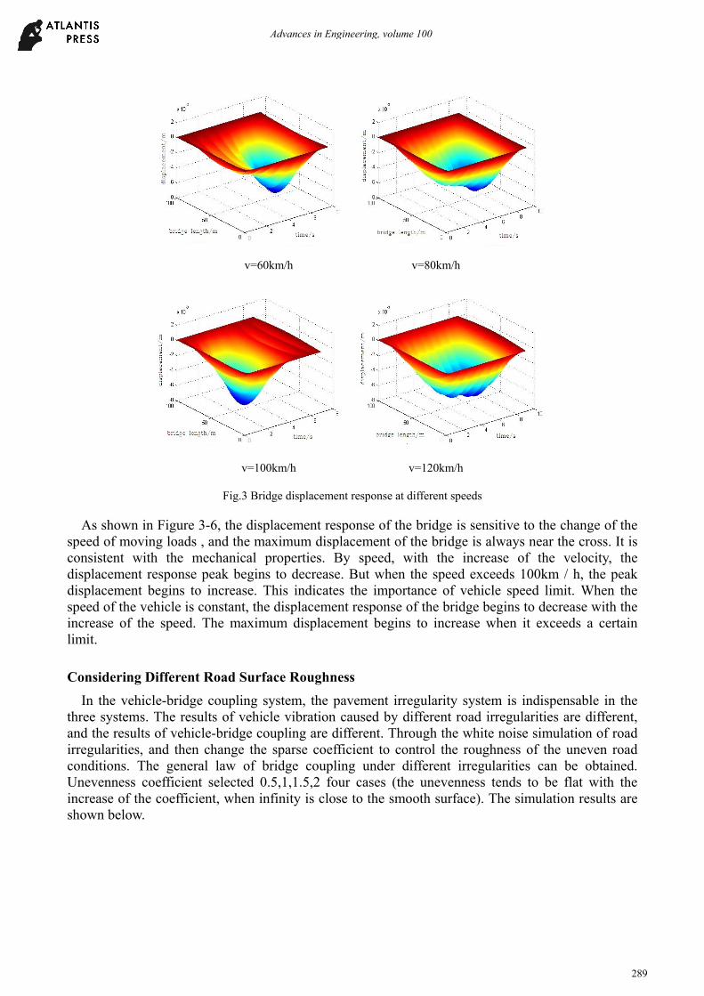
v=60km/h v=80km/h
v=100km/h v=120km/h
Fig.3 Bridge displacement response at different speeds
As shown in Figure 3-6, the displacement response of the bridge is sensitive to the change of the speed of moving loads , and the maximum displacement of the bridge is always near the cross. It is consistent with the mechanical properties. By speed, with the increase of the velocity, the displacement response peak begins to decrease. But when the speed exceeds 100km / h, the peak displacement begins to increase. This indicates the importance of vehicle speed limit. When the speed of the vehicle is constant, the displacement response of the bridge begins to decrease with the increase of the speed. The maximum displacement begins to increase when it exceeds a certain limit.
Considering Different Road Surface Roughness
In the vehicle-bridge coupling system, the pavement irregularity system is indispensable in the three systems. The results of vehicle vibration caused by different road irregularities are different, and the results of vehicle-bridge coupling are different. Through the white noise simulation of road irregularities, and then change the sparse coefficient to control the roughness of the uneven road conditions. The general law of bridge coupling under different irregularities can be obtained. Unevenness coefficient selected 0.5,1,1.5,2 four cases (the unevenness tends to be flat with the increase of the coefficient, when infinity is close to the smooth surface). The simulation results are shown below.
Advances in Engineering, volume 100
289

Coefficient = 0.5 Coefficient = 1
Coefficient = 1.5 Coefficient = 2
Fig.4 Displacement response of bridge under different irregularities
Fig.5 Displacement response of bridge under different irregularities
Fig.4 shows the displacement response of bridge under different road irregularities, Obviously, the four pictures are slightly different. While Fig.5 shows the difference of the displacements more intuitively. From Fig.5, when the coefficient changes from 0.5 to 1, the maximum displacement of the bridge increases, and the position of the occurrence approaches to the middle position. When the coefficient continues to increase, the maximum displacement begins to decrease, and the displacement response line tends to be gentle.
It can be concluded that, when the roughness coefficient is small ( the road is very uneven) , with the increase of the coefficient, the maximum displacement of the bridge increases, and the position of occurrence tends to cross. When the coefficient continues to increase, the maximum
Advances in Engineering, volume 100
290

displacement begins to decrease, and the position starts to change irregularly, but the value is small.
Conclusions
By introducing the relevant theory of white noise, the vehicle-bridge coupling vibration is studied through simulating the bridge deck irregularity. The simulation results show that, the occurrence position of the maximum deflection of the bridge which occurs in the cross-location, has nothing to do with the speed of the vehicle, but with the inherent properties of the bridge.When the speed of the vehicle increases in a certain range, the maximum displacement of the bridge begins to decrease, and when the speed exceeds a certain limit, the maximum displacement begins to increase. It shows the importance of bridge speed limit.
It can be got by changing the roughness of the road surface. When the roughness coefficient is small (the road is uneven), with the increase of the coefficient, the maximum displacement of the bridge increases, and the position tends to cross. When the coefficient continues to increase, it begins to decrease, and the position starts to change irregularly, but the value is small. To improve the driving comfort, it should be possible to control the unevenness in a small range.
References
[1] Michaltsos G,Sophianopulous D,Kounadis A N.The effect of a moving mass and other parameters on the dynamic response of a simply supported beam[J].Journal of Sound and Vibration,1996;191(3):357-362.
[2] Cai Y,Chen S S,Rote D M,et al.Vehicle/guidway interraction for high speed vehicles on a flexible guidway[J].Journal of Sound and Vibration,1994;175(5):625-646.
[3] LI J Q.A Unified Approach to Evolutionary Random Response Problems and Its Applications[D].Xi’an:Northwestern polytechnical university,2000.
[4] Crandall S H, Mark W D. Random vibration in mechanical systems. Academic Press,1963.
[5] Xia H,Zhang N,Guo W W,et al .Axle coupling vibration engineering[M].Beijing:Science press.,2014.
[6] Xia H.Vehicles and structure dynamic interaction[M]. Beijing:Science press,2002:1-5.
[7] Green M F,Cebon D. Dynamic response of highway bridges toheavy vehicles loads: theory and experimental vibration[J]. Journalof Sound and Vibration,1994,170( 1) : 51-78.
[8] Han W S.The research of wind - vehicle - bridge system space coupling vibration research[D].Shanghai: Tongji University,2006.
[9] Li Xiaozhen,Qiang Shizhong. State of the art review and trend ofstudies on vehicle-bridge interaction[J]. Journal of the China RailwaySociety,2002,24( 5) : 113-120.
[10] Shen Huoming,Xiao Xinbiao. Numerical method for vehicle-bridgecoupling vibrations [J]. Journal of Southwest Jiaotong University,2003,38( 6) : 658-662.
[11] Wang Zhiwei,Yang Chao. Current status and development trend ofmonitoring systems for expressway tunnels [J]. Modern TunnelingTechnology,2009,46( 6) : 8-13.
[12] Michaltsos G,Sophianopulous D,Kounadis A N.The effect of a moving mass and other parameters on the dynamic response of a simply supported beam[J].Journal of Sound and Vibration,1996;191(3):357-362.
[13] Cai Y,Chen S S,Rote D M,et al.Vehicle/guidway interraction for high speed vehicles on a flexible guidway[J].Journal of Sound and Vibration,1994;175(5):625-646.
Advances in Engineering, volume 100
291