numerical analysis of vibration and transient behaviour...
TRANSCRIPT

Scientia Iranica B (2018) 25(4), 2218{2232
Sharif University of TechnologyScientia Iranica
Transactions B: Mechanical Engineeringhttp://scientiairanica.sharif.edu
Research Note
Numerical analysis of vibration and transient behaviourof laminated composite curved shallow shell structure:An experimental validation
S.S. Sahoo, C.K. Hirwani, S.K. Panda�, and D. Sen
Department of Mechanical Engineering, National Institute of Technology, Rourkela, 769008, India.
Received 30 January 2017; received in revised form 13 April 2017; accepted 17 July 2017
KEYWORDSExperimentalvibration;Carbon/epoxycomposite;HSDT;FEM;ANSYS;Transient behaviour.
Abstract. The natural frequency and transient responses of carbon/epoxy layeredcomposite plate structure were analysed through the instrumentality of two higher-ordermid-plane kinematic models in this article. The mathematical formulation of the layeredcomposite structure was further utilised to develop a computer programme in MATLAB-15.0 to evaluate the mentioned responses. The practical relevance of the present higher-order models was established via comparing the present numerical results computed usingsuitable MATLAB computer code with the in-house experimental test data. Additionally,the fundamental frequency and transient responses of the carbon �bre-reinforced epoxycomposite plate structure were simulated via �nite-element package (ANSYS) by meansof the ANSYS Parametric Design Language (APDL) code. The simulated frequencieswere compared with those of the present experimental and MATLAB results. Finally,the signi�cance of the proposed higher-order kinematics was established via solving adi�erent kind of illustrations to investigate the in uence of various geometrical and materialparameters on the dynamic responses of layered composite structure, discussed in detail.© 2018 Sharif University of Technology. All rights reserved.
1. Introduction
The quest of designers to achieve lightweight structuralmaterials with reliable strength and sti�ness propertieshas led to the development of advanced materials,such as laminated composite. Owing to its superiorcharacteristics, laminated structures possess many ap-plications in high-performance engineering �elds, suchas aerospace, marine, automotive, and civil infrastruc-ture. The layered composites can provide tailor-made
*. Corresponding author. Tel.: +91 661 2462529E-mail addresses: [email protected] (S.S.Sahoo); [email protected] (C.K. Hirwani);[email protected], [email protected] (S.K. Panda);[email protected] (D. Sen).
doi: 10.24200/sci.2017.4346
properties due to their stacking sequence and layerthickness that, in turn, enhance the �nal structuralperformances during their service condition. Today,the laminated composite panel that creates the neces-sity for the accurate analysis and design of the �nal�nished product rapidly replaces most of the structuralcomponents. In general, most of the structures areexposed to the low/high amplitude of vibration underthe dynamic loading, and accurate prediction of the de-sired responses (fundamental frequency and transientresponse) is of great importance. The Finite-ElementMethod (FEM) is a potential method established as aversatile numerical tool from the last few decades toanalyse the laminated structural problems due to theirinherent materials and geometrical complexities. Manystudies on the development of the numerical model arereported where the structural responses are obtained

S.S. Sahoo et al./Scientia Iranica, Transactions B: Mechanical Engineering 25 (2018) 2218{2232 2219
using di�erent theories, such as classical as well as �rst-and higher-order shear deformation theories, includingthe modi�ed kinematic models, for accurate analysis.Further, to improve the accuracy of the numericalresults and reduce the experimental cost, studies havecontinued every now and then. Some of the veryrelevant and important studies have been reviewed andpresented in the following line, and few key de�cienciesin the former studies are pointed out.
Mallikarjuna and Kant [1] proposed a Finite-Element (EF) model in higher-order shear deforma-tion theory to analyse the dynamic behavior of thelayered composite plate structure. Similarly, theFEM solutions for frequency values of the doubly-curved shell panel were computed by Chakravorty etal. [2] using the First-order Shear Deformation Theory(FSDT). Further, the fundamental frequency responsesof the �bre-reinforced layered polymer composite platewere examined by Chakraborty and Mukhopadhyay [3]experimentally (impact excitation) and numericallyusing commercial FE package (NISA). Ahmadian andZangeneh [4] analysed the dynamic characteristics ofthe rectangular layered composite plate by means of asuperelement. The dynamic responses of thick multi-layered composite at/curved panel and sandwich platewere reported using the new HSDT [5,6] kinematicmodel. Further, Cugnoni et al. [7] computed the exper-imental modal test of Glass/Polypropylene compositeplate and performed the validation test by comparingthem with numerical results of the thin- and thick-layered composite shell panels computed via FSDTas well as the HSDT kinematic models. Tornabeneet al. [8] obtained the free vibration responses oflayered composite shell panel using a 2D higher-ordergeneral formulation. Jeyaraj et al. [9] analysedthe vibration and acoustic responses of an isotropicrectangular plate under the harmonic load, includingthe thermal environment, using di�erent types ofcommercial FE packages (ANSYS and SYSNOISE).Mehar et al. [10] computed the natural frequencyresponses of the functionally graded carbon nanotube(FG-CNT) composite plate using the HSDT mid-planekinematics. The free vibration and time-dependentdisplacement behaviour of the layered structure wereexamined based on the FSDT kinematics using aneight-node quadrilateral serendipity element [11-13].Later, Shokrollahi and Shafaghat [14] examined thedynamic behaviours of the hybrid metal-compositethick trapezoidal plates using global Ritz method inFSDT kinematics. The displacement kinematic usingFSDT was also considered by Kerur and Ghosh [15] tocompute the frequency responses of the layered com-posite panel and the active vibration control with in-tegrated Active Fiber Composite (AFC) layer. Kumarand Raju [16] analysed the dynamic responses of thecross- and angle-ply layered composite structures via
a mathematical model based on HSDT. The dynamicbehaviour of the square laminated plate with edgescontaining randomly and unidirectionally aligned short�bers was investigated by Eruslu and Aydogdu [17]using the FSDT kinematics. Similarly, the static anddynamic responses of the layered composite shallowshell panel using higher-order FEM model were ex-amined by Sahoo et al. [18] and validated with thecorresponding experimental values. Hirwani et al.[19] reported theoretical and experimental vibrationanalyses of debonded shell structure using di�erentkinematic models in association with FEM. The freevibration behaviour of the layered composite beam wasanalysed by Li et al. [20] using re�ned HSDT kinemat-ics. The static and dynamic [21-34] characteristics oflayered composite as well as sandwich structure usingmathematical model developed based on various theo-ries such as new trigonometric plate [35-37], new sinu-soidal higher-order plate [38,39], and hyperbolic sheardeformation theory [40,41] were analysed by Tounsiand his co-authors. The Large-amplitude dynamicbehaviour of curved panel was reported by Shooshtariand Razavi [42] using a Donnell shell theory. Milan etal. [43] computed the dynamic characteristic of thecarbon/epoxy layered composite at plate structureusing ANSYS.
It can be clearly observed from the above reviewsthat many numerical attempts have been already madeto investigate the dynamic responses of the layeredstructure via di�erent numerical as well as analyticaltechniques. It should be noted that the investigationof the fundamental frequency, including the time-dependent displacement responses of the layered com-posite structure, using the HSDT model and the sub-sequent validation with experimental and simulation(ANSYS) results, is very limited in numbers. Hence, toaddress the issue and overcome the shortcomings of theformer researchers, the current study aims to work as abridge between the gaps. In this regard, the present re-search focuses on the development of numerical modelto compute the fundamental frequencies and time-dependent de ections of the layered composite struc-ture using two di�erent HSDT models. Further, theresponses are evaluated using the homemade computercode in MATLAB software and experiments on car-bon/epoxy layered composite. The responses obtainedusing the theoretical and experimental are utilised fora comparison purpose to establish the requirement ofthe currently developed higher-order models. Again,the structural responses are computed via simulationmodel through structural simulation software (ANSYS)and compared with both the numerical and experimen-tal values. Finally, sensitivity analysis is carried outon di�erent parameters, such as shell panel geometries(cylindrical, spherical, at, hyperboloid, and elliptical),including the other geometrical and material parame-

2220 S.S. Sahoo et al./Scientia Iranica, Transactions B: Mechanical Engineering 25 (2018) 2218{2232
Figure 1. Geometry of laminated curved panel.
ters, to show their e�ects on the frequency and time-dependent displacement responses.
2. Theoretical formulation
2.1. Geometry of the panelFor the present investigation, a layered compositedoubly-curved shell panel with N number of or-thotropic layers of equal thickness has been considered,as presented in Figure 1. The following geometricalparameter of the panel is considered: the length asa, the breadth as b, and the thickness as h. Thedisplacement continuity within the layered composite isconsidered based on HSDT kinematics [44], where thein-plane displacement functions are de�ned as a cubicfunction of thickness co-ordinate, and the displacement�eld function in the thickness direction is assumed to beconstant or linearly varying throughout the thickness.In addition, the necessary assumptions on the currentmodelling purpose (uniform layer thickness, bondingbetween the layers, elastic behaviour of individualcomposite constituent, etc.) are made, similar to thereference [44].
2.2. Displacement �eld and straindisplacement relation
The displacement continuum for the �rst HSDT model(Model-1) is presented in Eq. (1), where displacementfunction in the thickness direction is considered con-stant through the thickness:
u(x; y; z; t) =u0(x; y; t) + z�x(x; y; t) + z2�x(x; y; t)
+ z3�x(x; y; t);
�(x; y; z; t) =�0(x; y; t) + z�y(x; y; t) + z2�y(x; y; t)
+ z3�y(x; y; t);
w(x; y; z; t) =w0(x; y; t): (1)
Further to the above, another HSDT kinematic modelsay, Model-2, is also employed for the current math-
ematical modelling of the layered composite panelstructure, where the displacement function through thethickness is assumed to be varying linearly [5]:
u(x; y; z; t) =u0(x; y; t) + z�x(x; y; t) + z2�x(x; y; t)
+ z3�x(x; y; t);
�(x; y; z; t) =�0(x; y; t) + z�y(x; y; t) + z2�y(x; y; t)
+ z3�y(x; y; t);
w(x; y; z; t) =w0(x; y; t) + z�z(x; y; t); (2)
where u, �, and w represent the translation of anypoint (within the laminate) along x, y, and z directions,respectively; t denotes the time, u0, �0, and w0 arethe mid-plane displacements, �x and �y denote therotations of the normal to the mid-plane about yand x directions, respectively. The rest of the terms�x; �y; �x; �y, and �z are the higher-order terms of Tay-lor series expansion, considered to maintain the actualpro�le of shear stress (parabolic variation) through thethickness of the layered composite structure.
Further, another model is developed in ANSYSpackage via the batch input technique of ANSYSParametric Design Language (APDL), code named asModel-3. The simulation model is discretised usinga well-de�ned SHELL-281 element. The SHELL-281element is an eight-node element with six degrees offreedom at each node and is suitable for the analysisof thin- to moderately thick-layered structures. Thedisplacement kinematics of the simulation model basedon FSDT [45] is shown in Eq. (3):
u(x; y; z; t) = u0(x; y; t) + z�x(x; y; t);
�(x; y; z; t) = �0(x; y; t) + z�y(x; y; t);
w(x; y; z; t) = w0(x; y; t) + z�z(x; y; t): (3)
Further, the constitutive equation is expressed in thefollowing line for any kth lamina within the laminate

S.S. Sahoo et al./Scientia Iranica, Transactions B: Mechanical Engineering 25 (2018) 2218{2232 2221
which is oriented at an arbitrary angle \�" about anyprincipal material axes:
f�ijg = [Qij ] f"ijg ; (4)
f�ijg, f"ijg, and [Qij ] represent the stress tensor, straintensor, and reduced sti�ness matrix, respectively. Theexpansion of the strain tensor can be presented furtheras follows:
f"ijg =
8>>>>>><>>>>>>:"xx"yy"zz xy xz yz
9>>>>>>=>>>>>>;=
8>>>>>>>>>>><>>>>>>>>>>>:
�@u@x + w
Rx
��@v@y + w
Ry
��@w@z
��@u@y + @v
@x
��@u@z + @w
@x � uRx
��@v@z + @w
@y � vRy
�
9>>>>>>>>>>>=>>>>>>>>>>>;; (5)
where Rx and Ry are the principal radii of curvaturein x and y axes, respectively.
2.3. Finite-element formulationThe FEM is a potential tool to analyse the structuralresponses of the layered composite structure withcomplex geometry. In the present formulation, thenecessary discretisations of the proposed model of thelayered structure have been performed through the useof suitable FEM steps using a nine-node isoparametricelement. Now, \d" as a displacement vector at an ar-bitrary point on the mid-surface of the panel structurefor all three models can be expressed in a generalisedform as follows:
d =nXi=1
Ni(x; y)di; (6)
where fdig = fu0iv0iw0i�xi�yi�xi�yi�xi�xigT , fdig =fu0i v0iw0i�xi�yi�zi�xi�yi�xi�yigT , and fdig = fu0iv0iw0i�xi�yi�zigT are displacement �eld functions forthe corresponding models (Model-1, Model-2, andModel-3) utilised in the current analysis. Similarly, Nirepresents the shape functions of the ith node.
Now, the strain tensor can be represented in thematrix form as follows:
f"g = [T ] f�"g ; (7)
where [T ] and f�"g denote the thickness coordinatematrix and mid-plane strain. Now, the mid-planestrain vector can be further explored and written asfollows:
f�"g = [BL] fdig ; (8)
where [BL] denotes the matrix of a general straindisplacement relation according to the type of displace-ment �eld model.
The total strain energy of the laminated panelis expressed in the following line using the strain andstress tensors and is expressed as follows:
U =12
x � +h=2Z�h=2
f"gT f�g dz�dxdy: (9)
Eq. (9) can be modi�ed further by substituting stressand strain relation, presented as follows:
U =12
x �f�"gT [D]f�"g
�dxdy; (10)
where [D] =+h=2R�h=2
[T ]T [Qij ][T ]dz.
The kinetic energy of the layered panel is pre-sented in terms of mass density and velocity as follows:
T =12
ZV
�n
_doT n _d
odV; (11)
where f _dg and � represent the global velocity vectorand mass density, respectively.
The free vibrated composite panel equation isformed using the necessary energy functional andsolved via Hamilton's principle. Finally, the equationof motion is expressed in the following line:
dt2Zt1
(T � U)dt = 0; (12)
where T represents the kinetic energy, and U representsthe strain energy.
Now, Eq. (12) can be rewritten by substitutingvalue of d, T , and U from Eqs. (6), (10), and (11):
[M ]f �dig+ [K]fdig = 0; (13)
where [M ], [K], �di, and di denote the mass matrices,sti�ness matrix, acceleration, and the displacement,respectively. The sti�ness and mass matrix can bewritten further as follows:
[K] =ZA
[BL]T [D][BL]dA;
[M ] =ZA
[N ]T [N ]�dA: (14)
Further, the �nal governing equation used to evaluatethe fundamental frequency response of the system inan eigenvalue form can be expressed as follows:
([K]� !2[M ])fdg = 0; (15)

2222 S.S. Sahoo et al./Scientia Iranica, Transactions B: Mechanical Engineering 25 (2018) 2218{2232
Figure 2. Representation of end conditions: (a)Simply-supported, (b) clamped, and (c) free end condition.
where ! is the fundamental frequency.Eq. (15) can be solved by applying di�erent sets
of constraint conditions (Figure 2(a)-(c)) at the edgesin order to decrease the number of unknowns and avoidany rigid body motion.
2.4. Newmark's integration scheme fortransient analysis
In order to obtain the time-dependent de ection re-sponses, Newmark's integration scheme has been em-ployed. The governing equation of the transient re-sponses accounts for the e�ects of the inertia, damping,and static de ection. The �nal form of the governingequation can be presented as follows:
[M ] �d+ [C] _d+ [K]d = [F ]; (16)
where [M ] represents the mass matrix, [C] denotesdamping matrix, [K] represents the sti�ness matrices,and [F ] is the externally applied load vector. Further,
the above-mentioned time-dependent motion equationis solved to compute the maximum de ection param-eter at the centre of the panel for total time `T '.The total time is divided into small time zones, e.g.time steps �t and the values are calculated for eachtime step. Di�erent integration parameters, such as�, �, and a0 to a7 of used Newmark's integration, areassumed to be the same as those de�ned in [46]. Theexpression for the e�ective sti�ness matrix at each timestep is expressed as follows:
[K̂] = [K] + a0[M ]: (17)
Similarly, the expression for the �nal load matrix andsuccessive time step (t + �t) implementation of thepresent analysis is presented in the following lines:
t+�t[F̂ ] = t+�t[F ] + [M ](a0td+ a2
t _d+ a3t �d): (18)
Further, the expression of the displacement, accelera-tion, and velocity can be presented as follows:
[K̂]t+�td =t+�t [F̂ ];
t+�t �d = a0(t+�td�t d)� a2t _d� a3
t �d;
t+�t _d =t _d+ a6t �d+ a7
t+�t �d: (19)
3. Results and discussion
The results and their corresponding discussions are re-ported in three major subsections. In the �rst section,the consistency and accuracy of the proposed HSDTmodels are examined via computing the dynamic andfree vibration responses of di�erent mesh re�nements,which are utilised for the comparison with those of theearlier published responses. Subsequently, the secondsubsection describes the experimental evaluation ofelastic properties and experimental dynamic responsesof carbon/epoxy layered composite structure. Afterthe validation of the present numerical model, somenew numerical illustrations are computed theoreticallyto show the importance of the present model andthe in uence of the other design parameters on thedynamic responses.
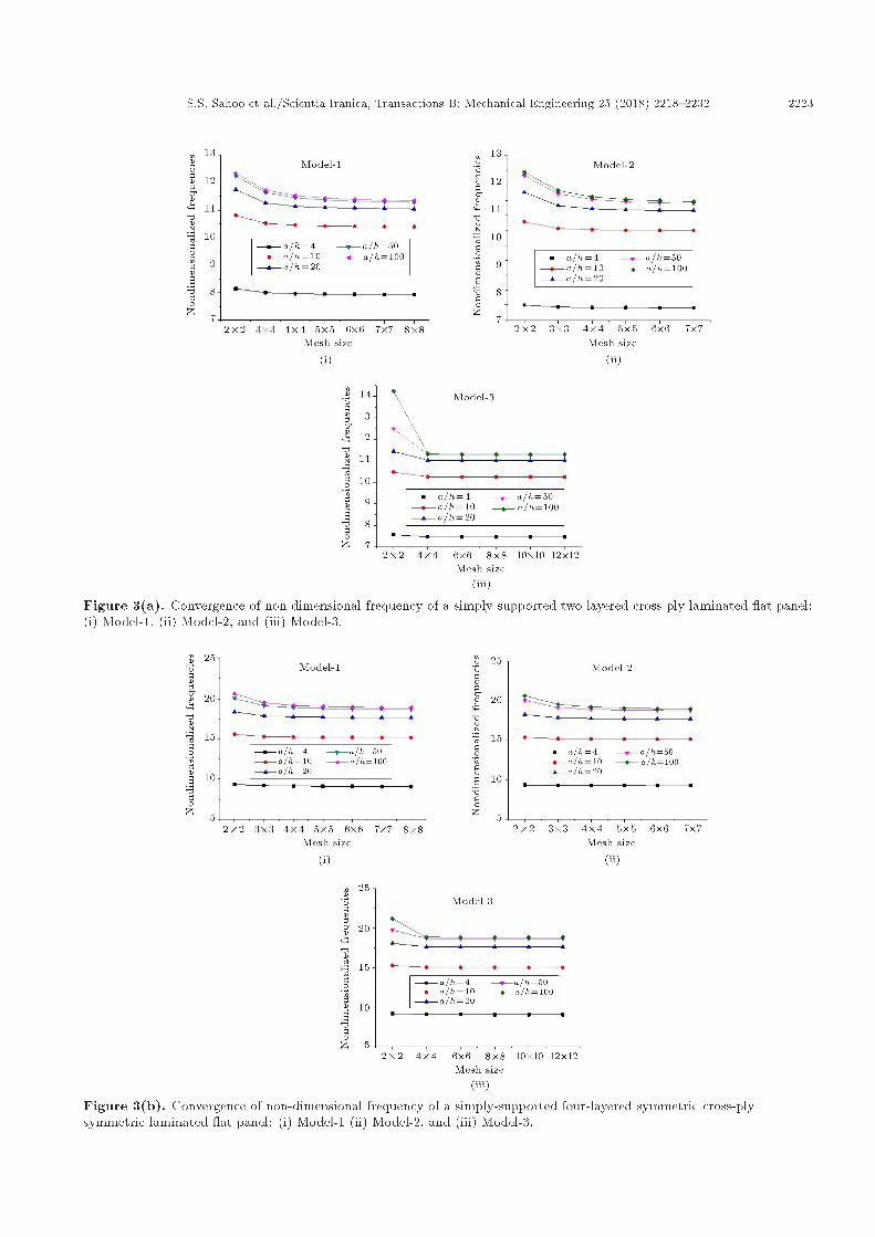
3.1. Stability and accuracy investigationThe stability of the present numerical models, i.e.Model-1 and Model-2, and the simulation model, i.e.Model-3, has been examined by analysing the vibrationand time-dependent de ection responses of layeredcomposite at plate structure for various mesh sizes, asshown in Figures 3(a) and 3(b), respectively. The non-dimensional natural frequencies of simply-supportedtwo-layer and four-layer symmetric cross-ply (0�/90�)layered at panels for �ve di�erent thickness ratios areobtained using the geometrical parameter, the same
S.S. Sahoo et al./Scientia Iranica, Transactions B: Mechanical Engineering 25 (2018) 2218{2232 2223
Figure 3(a). Convergence of non-dimensional frequency of a simply-supported two-layered cross-ply laminated at panel:(i) Model-1, (ii) Model-2, and (iii) Model-3.
Figure 3(b). Convergence of non-dimensional frequency of a simply-supported four-layered symmetric cross-plysymmetric laminated at panel: (i) Model-1 (ii) Model-2, and (iii) Model-3.

2224 S.S. Sahoo et al./Scientia Iranica, Transactions B: Mechanical Engineering 25 (2018) 2218{2232
Table 1. Non-dimensional frequency of a simply-supported two-layered and four-layered symmetric cross-ply laminated at panels.
Non-dimensional frequency
LaminationScheme
a=h Model-1 Model-2 Model-3Analytical
[5]
3DElasticity
[47]
Analytical[48]
Analytical[49]
(0�/90�)
4 7.9398 7.9043 7.4616 7.8908 8.3546 8.3546 8.088910 10.4134 10.4955 10.2501 10.4156 10.5680 10.5680 10.461020 11.0730 11.1693 11.0126 11.0509 11.1052 11.1052 11.063950 11.3221 11.4209 11.2631 11.2537 11.2751 11.2751 11.2558100 11.3854 11.487 11.3005 11.2837 11.3002 11.3002 11.2843
(0�=90�)s
4 9.0866 9.2694 9.0672 9.271 9.3235 10.2032 9.394910 15.1775 15.134 15.0329 15.0949 15.1073 15.9405 15.142620 17.6754 17.7127 17.6301 17.6434 17.6457 17.9938 17.659650 18.7214 18.7833 18.6754 18.6713 18.6718 18.7381 18.6742100 18.9384 19.0044 18.8426 18.8355 18.8356 18.8526 18.8362
as in [5] and M1 properties. The non-dimensionalnatural frequency throughout the analysis is obtainedvia the formulae: �! = !a2
h
q�Et , where ! represents
the fundamental frequency responses, if not statedotherwise. It has been seen from the convergence testthat the responses are converging well with di�erentmesh sizes. Accordingly, a mesh size of (6�6) is utilisedfor further investigation. In addition, the responsesof �ve side-to-thickness ratios (a=h= 4, 10, 20, 50and 100) are obtained, and then they are comparedwith those of the analytical and numerical responses ofreferences [5,47-49], as depicted in Table 1. Based onthe comparison, it is inferred that the present resultsshow good agreement with the published results ofdi�erent solution approaches.
3.2. Experimental validationIn the present section, the free vibration responsesare obtained experimentally for carbon/epoxy angle-ply at panels of two- and four-layer types undertwo support conditions (SFSF and CFFF), and theyare compared with the present FE responses obtainedusing all the three models. The comparison study isdepicted in Table 2. In this example, the elastic prop-erties of two- and four-layer composites are examinedexperimentally, namely M2 and M3, as presented inTable 3. For the evaluation, three specimens (alonglongitudinal, transverse, and inclined directions (45�tothe longitudinal direction)) are prepared following theinstruction given in the ASTM D3039/D3039M [50].The specimens are tested using Universal Testing Ma-chine (UTM) INSTRON-1195 at NIT, Rourkela. Allthe tests have been performed by �xing the loadingrate as 1 mm/min. The UTM and the broken (tested)specimens of the carbon/epoxy layered composite are
Figure 4(a). Tensile testing machine (INSTRON 1195).
provided in Figures 4(a) and 4(b), respectively. It isnecessary to mention that Poison's ratio for the currentanalysis is the same as that in [51]. Additionally, theshear modulus for each set of the laminate has beenobtained via the general formula available in [52]:
Glt =1
4E45� 1
El � 1Et � 2�12
El
!:
Now, the vibration test is conducted using the home-made experimental set-up at parent Institute (NITRourkela), and the corresponding data are recordedvia cDAQ-9178 (National Instruments). The instru-ment is an eight-channel compact data acquisition

S.S. Sahoo et al./Scientia Iranica, Transactions B: Mechanical Engineering 25 (2018) 2218{2232 2225
Table 2. Natural frequency (Hz) of two-layered and four-layered symmetric angle-ply carbon/epoxy laminated composites at panel under SFSF and CFFF support.
Supportcondition
Laminationscheme
Modeno.
Frequency (Hz)Experiment Model-1 Model-2 Model-3
SFSF
[�45�]
1 88 91.36 97.31531 90.4032 180 169.8 174.1709 169.343 377 380.1 409.3941 364.754 437 438.4 468.2937 435.75 484 475.5 501.2964 463.28
[�45�]s
1 161 165.577 175.1591 164.412 307 319.80 326.2955 320.403 667 683.90 730.8636 664.594 827 817.30 869.75 815.805 868 873.70 911.9091 862.04
CFFF
[�45�]
1 33.5 32.79 35.45 32.582 81.5 79.88 81.73 78.9333 210 207.38 217.93 200.674 249 257.44 262.14 253.055 302 296.73 308.84 287.93
[�45�]s
1 62.5 60.07 63.96 59.772 152 151.40 153.23 149.523 378 371.47 383.40 362.754 485 477.87 494.8 470.595 561 549.98 562.36 536.25
Table 3. Material properties.
Properties Material-1(M1)
Material-2(M2)
Material-3(M3)
Material-4(M4)
Young's modulus in x direction (El) 40 Et 6.695 GPa 6.469 GPa 53.5 GPa
Young's modulus in y direction (Et) 1 GPa 6.314 GPa 5.626 GPa 2.1 GPa
Young's modulus in z direction (Ez) Et 6.314 GPa 5.626 GPa 53.5 GPa
Shear modulus (Glt) 0.6 Et 2.7 GPa 2.05 GPa 1.05 GPa
Shear modulus (Gtz) 0.5 Et 1.35 GPa 1.025 GPa 1.05 GPa
Shear modulus (Glz) 0.6 Et 2.7 GPa 2.05 GPa 1.05 GPa
Poisson's ratio (�lt) 0.25 0.17 0.17 0.25
Poisson's ratio (�lz) 0.25 0.17 0.17 0.25
Poisson's ratio (�tz) 0.25 0.17 0.17 0.25
Density (�) 1900 kgm�3 1900 kgm�3 1900 kgm�3 800 kgm�3
system that can be used for a variety of mechanicalmeasurements (temperature, strain, load, pressure,torque, acceleration, and acoustics) and a pictorialform of the same, as presented in Figure 5(a). Thefrequency responses are recorded for the carbon/epoxycomposite at panel structure under SFSF supportcondition. Initially, the panel is excited with an
electronic impact hammer at any arbitrary point on thestructure (Figure 5(b)), and the output signal is sensedvia an accelerometer mounted on the structural panel.The accelerometer is a type of sensor that capturesthe acceleration, converts it into an analogue voltagesignal, and processes to a cDAQ where the analoguesignal is further converted into digital signal via the

2226 S.S. Sahoo et al./Scientia Iranica, Transactions B: Mechanical Engineering 25 (2018) 2218{2232
Figure 4(b). Carbon/epoxy composite at panelspecimen after tensile test.
Figure 5(a). CDAQ 9178 national instruments anddisplay.
Figure 5(b). Experimental set-up for free vibrationanalysis.
inbuilt analogue-digital converter. Now, the signal isprocessed further via a well-known signal processingsoftware, named LABVIEW. The LABVIEW operatesthrough three main panels: front panel, block diagram,and the connector panel. The front panel is also calledthe user interface panel where the recorded data canbe seen in the form of a graph or numeric as peruser's interest. Further, the block diagram, which is aprogramming window, and the necessary programmingcan be changed, called Virtual Instrument (VI). Thiscan be performed to process the input signal and getthe desired form of output. Herein, the block diagramis mainly used to capture the frequency responses ofthe laminate structure, whose details are provided inFigure 5(c). The input acceleration signal comingfrom the cDAQ now passes through a power spectrummodule, as shown in the block diagram, to convertit into the time-domain and frequency-domain forms.The necessary frequency responses obtained from theacceleration signal are kept for the future use, i.e.validation purposes. Finally, the captured frequencyresponses of carbon/epoxy layered composite platehave been compared with the numerical and simulatedresponses computed from the proposed and ANSYSmodels, as shown in Table 2. The comparison studyclearly indicates the accuracy and necessity of thecurrent HSDT models (Model-1 and Model-2) insteadof FSDT model, i.e. Model-3.
3.3. Transient responseNow, the present models are extended to computethe transient behaviour of three di�erent at panelcases. In the present comparison study, the transientbehaviors of a single-layered orthotropic plate anda four-layered square angle-ply laminated compositeplate with simply-supported edges are examined underuniformly distributed step load (q0 = 0:1 N=mm2) Thetransient responses are computed using the presentnumerical models (Model-1 and Model-2) as well asthe simulation model ANSYS (Model-3) by settingthe time step to 10 �s. For this analysis, the paneldimension of 250 mm length and 5 mm height is takenwith M4 material properties, as given in Table 3. Thetransient responses of single-layer and four-layer angle-ply (�45�)s layered composite panels are comparedwith the available published responses [53,54], as plot-ted in Figures 6(a) and 6(b), respectively. The �guresclearly show that the responses are in close agreementwith the previously reported responses.
3.4. Numerical examplesThe convergence and validation results clearly indicatethat the present developed HSDT models are capa-ble enough to analyse the time-dependent de ectionand vibration characteristics of the layered compositestructure with adequate accuracy. Now, the models are

S.S. Sahoo et al./Scientia Iranica, Transactions B: Mechanical Engineering 25 (2018) 2218{2232 2227
Figure 5(c). Block diagram of the LABVIEW software.
Figure 6(a). Central de ection versus time response ofsingle-layered orthotropic laminated at panel to a stepload (0.1 N/mm2).
utilised further to solve a new example to enhance thequantitative understanding on in uence of the designparameters (the thickness ratios, the curvature ratios,the support conditions) on dynamic responses of thelayered composite plate/shell structure.
3.4.1. In uence of support conditions on fundamentalfrequency response
It is well known that di�erent support conditionsof the composite structure a�ect the overall sti�nessand, further, the structural responses signi�cantly.In the current example, the in uence of the support
Figure 6(b). Central de ection versus time response ofsimply-supported four-layered angle-ply laminated atpanel to a step load (0.1 N/mm2).
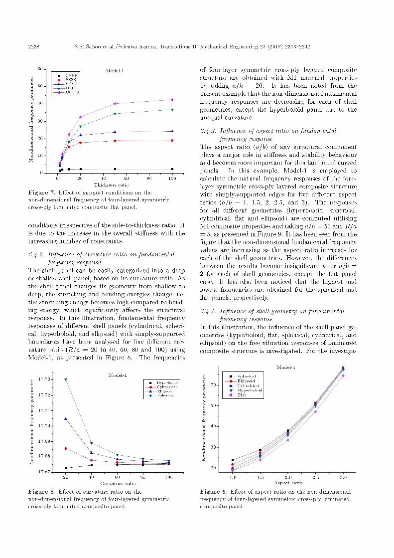
condition on frequency responses of the square four-layer cross-ply laminated plates with M1 materialproperties has been investigated. The responses areevaluated for �ve di�erent end conditions: CCCC (all-edge clamped), SCSC (two-edge simply-supported andtwo-edge clamped), SSSS (all-edge simply-supported),CFCF (two-edge clamped and two-edge free), andCFFF (one-edge clamped and others free, i.e. can-tilever) and �ve side-to-thickness ratios (a=h = 2, 4,10, 20, 50, and 100) using Model-1 and presentedin Figure 7. It is observed from the Figure thatthe nonlinear vibration responses are in the ascendingorder with CFFF, SSSS, SCSC, CFCF, and CCCC end
2228 S.S. Sahoo et al./Scientia Iranica, Transactions B: Mechanical Engineering 25 (2018) 2218{2232
Figure 7. E�ect of support conditions on thenon-dimensional frequency of four-layered symmetriccross-ply laminated composite at panel.
conditions irrespective of the side-to-thickness ratio. Itis due to the increase in the overall sti�ness with theincreasing number of constraints.
3.4.2. In uence of curvature ratio on fundamentalfrequency response
The shell panel can be easily categorized into a deepor shallow shell panel, based on its curvature ratio. Asthe shell panel changes its geometry from shallow todeep, the stretching and bending energies change, i.e.the stretching energy becomes high compared to bend-ing energy, which signi�cantly a�ects the structuralresponse. In this illustration, fundamental frequencyresponses of di�erent shell panels (cylindrical, spheri-cal, hyperboloid, and ellipsoid) with simply-supportedboundaries have been analysed for �ne di�erent cur-vature ratio (R=a = 20 to 40, 60, 80 and 100) usingModel-1, as presented in Figure 8. The frequencies
Figure 8. E�ect of curvature ratio on thenon-dimensional frequency of four-layered symmetriccross-ply laminated composite panel.
of four-layer symmetric cross-ply layered compositestructure are obtained with M1 material propertiesby taking a=h = 20. It has been noted from thepresent example that the non-dimensional fundamentalfrequency responses are decreasing for each of shellgeometries, except the hyperboloid panel due to theunequal curvature.
3.4.3. In uence of aspect ratio on fundamentalfrequency response
The aspect ratio (a=b) of any structural componentplays a major role in sti�ness and stability behaviourand becomes more important for thin laminated curvedpanels. In this example, Model-1 is employed tocalculate the natural frequency responses of the four-layer symmetric cross-ply layered composite structurewith simply-supported edges for �ve di�erent aspectratios (a=b = 1, 1.5, 2, 2.5, and 3). The responsesfor all di�erent geometries (hyperboloid, spherical,cylindrical, at and ellipsoid) are computed utilisingM1 composite properties and taking a=h = 50 and R=a= 5, as presented in Figure 9. It has been seen from the�gure that the non-dimensional fundamental frequencyvalues are increasing as the aspect ratio increases foreach of the shell geometries. However, the di�erencesbetween the results become insigni�cant after a=b =2 for each of shell geometries, except the at panelcase. It has also been noticed that the highest andlowest frequencies are obtained for the spherical and at panels, respectively.
3.4.4. In uence of shell geometry on fundamentalfrequency response
In this illustration, the in uence of the shell panel ge-ometries (hyperboloid, at, spherical, cylindrical, andellipsoid) on the free vibration responses of laminatedcomposite structure is investigated. For the investiga-
Figure 9. E�ect of aspect ratio on the non-dimensionalfrequency of four-layered symmetric cross-ply laminatedcomposite panel.
S.S. Sahoo et al./Scientia Iranica, Transactions B: Mechanical Engineering 25 (2018) 2218{2232 2229
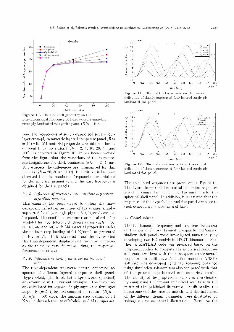
Figure 10. E�ect of shell geometry on thenon-dimensional frequency of four-layered symmetriccross-ply laminated composite panel (R=a = 10).
tion, the frequencies of simply-supported square four-layer cross-ply symmetric layered composite panel (R=a= 10) with M1 material properties are obtained for sixdi�erent thickness ratios (a=h = 2, 4, 10, 20, 50, and100), as depicted in Figure 10. It has been observedfrom the �gure that the variations of the responsesare insigni�cant for thick laminates (a=h = 2, 4, and10), whereas the di�erences are pronounced for thinpanels (a=h = 20, 50 and 100). In addition, it has beenobserved that the maximum frequencies are obtainedfor the spherical geometry, and the least frequency isobtained for the at panels.
3.4.5. In uence of thickness ratio on time-dependentde ection response
This example has been solved to obtain the time-dependent de ection responses of the square, simply-supported four-layer angle-ply (�45�)s layered compos-ite panel. The mentioned responses are obtained usingModel-1 for �ve di�erent thickness ratios (a=h = 30,35, 40, 45, and 50) with M4 material properties underthe uniform step loading of 0.1 N/mm2, as presentedin Figure 11. It is observed from the �gure thatthe time-dependent displacement response increasesas the thickness ratio increases; thus, the responses'frequencies decrease.
3.4.6. In uence of shell geometries on transientbehaviour
The time-dependent transverse central de ection re-sponses of di�erent layered composite shell panels(hyperboloid, cylindrical, at, ellipsoid, and spherical)are examined in the current example. The responsesare calculated for square, simply-supported four-layerangle-ply (�45�)s layered composite structure (R=a =10, a=h = 50) under the uniform step loading of 0.1N/mm2 through the use of Model-1 and M4 properties.
Figure 11. E�ect of thickness ratio on the centralde ection of simply-supported four-layered angle-plylaminated at panel.
Figure 12. E�ect of curvature ratio on the centralde ection of simply-supported four-layered angle-plylaminated at panel.
The calculated responses are presented in Figure 12.The �gure shows that the central de ection responsesare at maximum for at panel and at minimum for thespherical shell panel. In addition, it is inferred that theresponses of the hyperboloid and at panel are close toeach other in a few instances of time.
4. Conclusions
The fundamental frequency and transient behaviourof the carbon/epoxy layered composite at/curvedshallow shell panels were investigated numerically bydeveloping two FE models in HSDT kinematic. Fur-ther, a MATLAB code was prepared based on theproposed models to compute the numerical responsesand compare them with the subsequent experimentalresponses. In addition, a simulation model in ANSYSsoftware was developed, and the response obtainedusing simulation software was also compared with thatof the present experimental and numerical results.The validity of the proposed models was also checkedby comparing the present numerical results with theresult of the published literature. Additionally, theimportance of the present models and the in uencesof the di�erent design parameter were illustrated bysolving a new numerical illustration. Based on the

2230 S.S. Sahoo et al./Scientia Iranica, Transactions B: Mechanical Engineering 25 (2018) 2218{2232
convergence, validation, and parametric study, thefollowing conclusions were drawn and discussed be-low:
a) The convergence and validation study of the pro-posed HSDT models clearly indicate that the pre-sented models are suitable for the fundamentalfrequency and time dependent-de ection responseof the layered composite at/curved shallow shellstructure;
b) The parametric studies show that di�erent geome-tries of the shell panel considerably a�ect bothvibration and transient responses;
c) The fundamental frequencies are at maximum forthe spherical and at minimum for the plate struc-ture. In addition, the time-dependent de ectionresponses are at maximum for the plate and at min-imum for the layered spherical composite structure;
d) The side-to-thickness ratio, constraint conditions,curvature ratio, and aspect ratio a�ect the fun-damental frequency and time-dependent transversede ection of the at/curved shallow shell panelsigni�cantly.
Acknowledgements
This work is under the project sanctioned by theDepartment of Science and Technology (DST) throughgrant SERB/F/1765/2013-2014 Dated: 21/06/2013.Authors are grateful to DST, Govt. of India for theirconsistent support.
References
1. Mallikarjuna, B. and Kant, T. \Dynamics of laminatedcomposite plates with a higher order theory and �niteelement discretization", J. Sound and Vibr., 126(3),pp. 463-475 (1988).
2. Chakravorty, D., Bandyopadhyay, J.N., and Sinha,P.K. \Finite element free vibration analysis of doublycurved laminated composite shells", J. Sound andVibr., 191(4), pp. 491-504 (1996).
3. Chakraborty, S. and Mukhopadhyay, M. \Free vibra-tional responses of FRP composite plates: Experi-mental and numerical studies", J. Reinf Plast Comp.,19(7), pp. 535-551 (2000).
4. Ahmadain, M.T. and Zangeneh, M.S. \Forced vi-bration analysis of laminated rectangular plate usingsuper element", Scientia Iranica, 10(2), pp. 260-265(2003).
5. Kant, T. and Swaminathan, K. \Analytical solutionsfor free vibration of laminated composite and sandwichplates based on higher order re�ned theory", Compos.Struct., 53, pp. 73-85 (2001).
6. Mantari, J.L., Oktem, A.S., and Soares, C.G. \Staticand dynamic analysis of laminated composite andsandwich plates and shells by using a new higher-ordershear deformation theory", Compos. Struct., 94, pp.37-49 (2011).
7. Cugnoni, J., Gmur, T., and Schorderet, A. \Iden-ti�cation by modal analysis of composite structuresmodelled with FSDT and HSDT laminated shell �niteelements", Compos: Part A., 35, pp. 977-987 (2004).
8. Tornabene, F., Viola, E., and Fantuzzi, N. \Generalhigher-order equivalent single layer theory for freevibrations of doubly-curved laminated composite shellsand panels", Compos. Struct., 104, pp. 94-117 (2013).
9. Jeyaraj, P., Padmanabhan, C., and Ganesan, N.\Vibration and acoustic response of an isotropic platein a thermal environment", ASME J. Vib Acoust.,130(5), p. 051005 (2008).
10. Mehar, K., Panda, S.K., Dehengia, A., and Kar,V.R. \Vibration analysis of functionally graded car-bon nanotube reinforced composite plate in thermalenvironment", J. of Sandw. Struct. and Mater., 18(2),pp. 151-173 (2015).
11. Ghafoori, E. and Asghari, M. \Dynamic analysis oflaminated composite plates traversed by a movingmass based on a �rst-order theory", Compos. Struct.,92, pp. 1865-1876 (2010).
12. Maleki, S., Tahani, M., and Andakhshideh, A. \Tran-sient response of laminated plates with arbitrarylaminations and boundary conditions under generaldynamic loadings", Arch. Appl. Mech., 82, pp. 615-630 (2012).
13. Diacenco, A., Jorge, A.B. and Silva, P. \Dynamic anal-ysis of the in uence of �ber orientation in compositelaminated plates", J. Mech. Eng. Res., 7(1), pp. 1-8(2015).
14. Shokrollahi, S. and Shafaghat, S. \A global Ritzformulation for the free vibration analysis of hybridmetal-composite thick trapezoidal plates", ScientiaIranica B., 23(1), pp. 249-259 (2016).
15. Kerur, S.B. and Ghosh, A. \Active vibration controlof composite using AFC actuator and PVDF sensor",J. Intel Mat. Syst. Str., 22(11), pp. 1149-1160 (2011).
16. Kumar, J.S., Raju, T.D., and Reddy, K.V.K. \Vi-bration analysis of composite laminated plates usinghigher-order shear deformation theory with zig-zagfunction", Indian J Sci Technol, 4(8), pp. 960-966(2011).
17. Eruslu, S.O. and Aydogdu, M. \Free vibration analysisof short �ber reinforced laminated plates with �rstshear deformation theory", Turkish J. Eng. Env. Sci.,36, pp. 95-107 (2012).
18. Sahoo, S.S., Panda, S.K., and Mahapatra, T.R.,\Static, free vibration and transient response of lami-nated composite curved shallow panel - An experimen-tal approach", Eur. J. Mech. A-Solid., 59, pp. 95-113(2016).
S.S. Sahoo et al./Scientia Iranica, Transactions B: Mechanical Engineering 25 (2018) 2218{2232 2231
19. Hirwani, C.K., Patil, R.K., Panda, S.K., Mahapatra,S.S., Mandal, S.K., Srivastava, L., and Buragohain,M.K. \Experimental and numerical analysis of freevibration of delaminated curved panel", Aerosp. Sci.Technol., 54, pp. 353-370 (2016).
20. Li, J., Huo, Q., Li, X., Kong, X., and Wu, W.\Vibration analyses of laminated composite beamsusing re�ned higher-order shear deformation theory",Int. J. Mech. Mater. Des., 10, pp. 43-52 (2014).
21. Bessaim, A., Houari, M.S.A., Tounsi, A., Mahmoud,S.R., and Adda Bedia, E.A. \A new higher-order shearand normal deformation theory for the static and freevibration analysis of sandwich plates with functionallygraded isotropic face sheets", J. Sandw. Struct. Mater.,15, pp. 671-703 (2013).
22. Bouderba, B., Houari, M.S.A., and Tounsi, A. \Ther-momechanical bending response of FGM thick platesresting on Winkler-Pasternak elastic foundations",Steel and Compos. Struct., 14(1), pp. 85-104 (2013).
23. Zidi, M., Tounsi, A., Houari, M.S.A., and B�eg, O.A.\Bending analysis of FGM plates under hygro-thermo-mechanical loading using a four variable re�ned platetheory", Aerospace Sci. Tech., 34, pp. 24-34 (2014).
24. Fekrar, A., Houari, M.S.A., Tounsi, A., and Mahmoud,S.R. \A new �ve-unknown re�ned theory based on neu-tral surface position for bending analysis of exponentialgraded plates", Meccanica, 49, pp. 795-810 (2014).
25. Belabed, Z., Houari, M.S.A., Tounsi, A., Mahmoud,S.R., and Anwar B�eg, O. \An e�cient and simplehigher order shear and normal deformation theory forfunctionally graded material (FGM) plates", Compos:Part B., 60, pp. 274-283 (2014).
26. Bourada, M., Kaci, A., Houari, M.S.A., and Tounsi, A.\A new simple shear and normal deformations theoryfor functionally graded beams", Steel and Compos.Struct., 18(2), pp. 409-423 (2015).
27. Ait Yahia, S., Ait Atmane, H., Houari, M.S.A., andTounsi, A. \Wave propagation in functionally gradedplates with porosities using various higher-order sheardeformation plate theories", Struct. Eng. Mech., 53(6),pp. 1143-1165 (2015).
28. Tounsi, A., Houari, M.S.A., and Bessaim, A. \A new3-unknowns non-polynomial plate theory for bucklingand vibration of functionally graded sandwich plate",Struct. Eng. Mech., Int. J., 60(4), pp. 547-565 (2016).
29. Bennoun, M., Houari, M.S.A., and Tounsi, A. \A novel�ve variable re�ned plate theory for vibration analysisof functionally graded sandwich plates", Mech. Adv.Mater. Struc., 23(4), pp. 423-431 (2016).
30. Bouderba, B., Houari, M.S.A., Tounsi, A., and Hassan,S. \Thermal stability of functionally graded sand-wich plates using a simple shear deformation theory",Struct. Eng. Mech., 58(3), pp. 397-422 (2016).
31. Bellifa, H., Benrahou, K.H., Hadji, L., Houari, M.S.A.,and Tounsi, A. \Bending and free vibration analysisof functionally graded plates using a simple shear
deformation theory and the concept the neutral surfaceposition", J. Braz. Soc. Mech. Sci. Eng., 38(1), pp.265-275 (2016).
32. Bousahla, A.A., Benyoucef, S., Tounsi, A., and Has-san, S. \On thermal stability of plates with function-ally graded coe�cient of thermal expansion", Struct.Eng. Mech., 60(2), pp. 313-335 (2016).
33. Draiche, A., Tounsi, A., and Hassan, S. \A re�nedtheory with stretching e�ect for the exure analysisof laminated composite plates", Geomech and Eng.,11(5), pp. 671-690 (2016).
34. Chikh, A., Tounsi, A., Habib, H., and Hassan, S.\Thermal buckling analysis of cross-ply laminatedplates using a simpli�ed HSDT", Smart. Struct. Syst.,19(3), pp. 289-297 (2017).
35. Tounsi, A., Houari, M.S.A., Benyoucef, S., and AddaBedia, E.A. \A re�ned trigonometric shear deforma-tion theory for thermoelastic bending of functionallygraded sandwich plates", Aerospace Sci. Tech., 24, pp.209-220 (2013).
36. Draiche, K., Tounsi, A., and Khal�, Y. \A trigono-metric four variable plate theory for free vibration ofrectangular composite plates with patch mass", SteelCompos. Struct., 17(1), pp. 69-81 (2014).
37. Beldjelili, Y., Tounsi, A., and Mahmoud, S.R. \Hygro-thermo-mechanical bending of S-FGM plates restingon variable elastic foundations using a four-variabletrigonometric plate theory", Smart Struct. Syst., Int.J., 18(4), pp. 755-786 (2016).
38. Hamidi, A., Houari, M.S.A., Mahmoud, S.R., Tounsi,A. \A sinusoidal plate theory with 5-unknowns andstretching e�ect for thermomechanical bending of func-tionally graded sandwich plates", Steel and Compos.Struct., 18(1), pp. 235-253 (2015).
39. Houari, M.S.A., Tounsi, A., Bessaim, A., and Mah-moud, S.R. \A new simple three-unknown sinu-soidal shear deformation theory for functionally gradedplates", Steel and Compos. Struct., 22(2), pp. 257-276(2016).
40. Hebali, H., Tounsi, A., Houari, M.S.A., Bessaim, A.,and Bedia, E.A.A. \A new quasi-3D hyperbolic sheardeformation theory for the static and free vibrationanalysis of functionally graded plates", ASCE J. Eng.Mech., 140, pp. 374-383 (2014).
41. Mahi, A., Adda Bedia, E.A., and Tounsi, A. \Anew hyperbolic shear deformation theory for bendingand free vibration analysis of isotropic, functionallygraded, sandwich and laminated composite plates",Appl. Math. Model., 39, pp. 2489-2508 (2015).
42. Shooshtari, A. and Razavi, S. \Large-amplitude freevibration of magneto-electro-elastic curved panels",Scientia Iranica B., 23(6), pp. 2606-2615 (2016).
43. Milan, Z., Josef, S., Lenka, R., and Jan, S. \Finiteelement transient dynamic analysis of laminated com-

2232 S.S. Sahoo et al./Scientia Iranica, Transactions B: Mechanical Engineering 25 (2018) 2218{2232
posite plates", Appl. Mech. Mater., 732, pp. 357-364(2015).
44. Reddy, J.N., Mechanics of Laminated CompositePlates and Shells", 2nd Ed., Florida, CRC Press(2004).
45. Szekrenyes, A. \Analysis of classical and �rst-ordershear deformable cracked orthotropic plates", J. Com-pos. Mater., 48(12), pp. 1441-1457 (2013).
46. Bathe, K.J., Finite Element Procedures in EngineeringAnalysis, New Jersey, Prentice-Hall (1982).
47. Whitney, J.M. and Pagano, N.J. \Shear deformationin heterogeneous anisotropic plates", J. Appl. Mech.,37(4), pp. 1031-1036 (1970).
48. Reddy, J.N. \A simple higher order theory for lami-nated composite plates", J. Appl. Mech., 51, pp. 745-752 (1984).
49. Senthilnathan, N.R., Lim, K.H., and Chow, S.T.\Buckling of shear deformation plate", AIAA, 25(9),pp. 1268-1271 (1987).
50. ASTM D 3039/D 3039M, Standard Test Method forTensile Properties of Polymer Matrix Composite Ma-terials (2006).
51. Crawley, E.F. \The natural modes of graphite/epoxycantilever plates and shells", J. Compos. Mater., 13,pp. 195-205 (1979).
52. Jones, R.M., Mechanics of Composite Materials, 2ndEd., Philadelphia, Taylor and Francis (1975).
53. Chen, J., Dawe, D.J., and Wang, S. \Nonlineartransient analysis of rectangular composite laminatedplates", Compos. Struct., 49, pp. 129-139 (2000).
54. Wang, S., Chen, J., and Dawe, D.J. \Linear transientanalysis of rectangular laminates using spline �nitestrips", Compos. Struct., 41, pp. 57-66 (1998).
Biographies
Sushreee Sasmita Sahoo completed MTech (Re-search) from the Department of Mechanical Engineer-ing NIT, Rourkela. Her skills and expertise includelaminated composites, �nite-element analysis pertain-ing to mechanical behaviour of composite materials,and experimental vibration analysis.
Chetan Kumar Hirwani is pursuing his PhD atthe Department of Mechanical Engineering, NIT,Rourkela. He has been working on the nonlinearbehaviour of delaminated composite plates/shells sincethe last one and half year via experimental and nu-merical study of di�erent kinds of advanced compositecomponents including the simulation. His area ofinterest is �nite-element analysis of damaged mod-elling of laminated composite plate and shell struc-tures.
Subrata Kumar Panda received his PhD degreefrom IIT Kharagpur, India in 2009. He is working as anAssistant Professor at the Department of MechanicalEngineering, NIT, Rourkela. His current researchinterests include nonlinear solid mechanics, smartcomposite structures, nonlinear FEM, experimentalvibrations, functionally graded materials, SMA, PZTand magnetostrictive material, bio-mechanical analysisof functional materials.
Deeprodyuti Sen completed MTech from the De-partment of Mechanical Engineering NIT, Rourkela.His areas of interests are �nite-element modelling andanalysis of the mechanical behaviour of compositestructure such as layered and nano composites.