numerical investigation of heat transfer and pressure drop
TRANSCRIPT

J Ther Eng, Vol. 7, No. 6, pp. 1417–1431, September, 2021
ABSTRACT
This paper presents a numerical simulation to determine the air-side heat transfer and the pressure drop characteristics of a flat tube heat exchanger with offset strip fin. The effects of the fin bending ratio such as 29%, 36%, 44%, 50%, and the fin spacing such as 2.10 mm, 2.35 mm, 2.60 mm on the performance of the heat exchanger are studied by using a commercial CFD software. The air having constant viscosity, thermal conductivity, and density enters the heat exchanger at 298 K and the wall temperature of the strip fins is considered as constant at 314 K. Variations of the heat transfer coefficient and the pressure drop in the airside are presented with respect to the frontal air velocity while Colburn j-factor and the friction factor f are presented with respect to the airside Reynolds number ranging from 200 to 1200. Finally, the thermal-hydraulic performance of all investigated cases is compared by using the volume goodness factor, j/f 1/3. The results show that the air-side heat transfer coefficient and the pres-sure drop increase when the frontal air velocity ascends. The air-side heat transfer coefficient decreases with the increase of fin spacing. The fin bending ratio does not have a significant ef-fect on the pressure drop in the considered fin spacing. Both the Colburn j-factor and friction factor reduce with the increment of Reynolds number and fin spacing.
Cite this article as: Doğan B, Öztürk MM, Erbay B. Numerical investigation of heat transfer and pressure drop characteristics in an offset strip fin heat exchanger. J Ther Eng 2021;7(6): 1417–1431.
Journal of Thermal EngineeringWeb page info: https://jten.yildiz.edu.tr
DOI: 10.18186/thermal.990795
Research Article
Numerical investigation of heat transfer and pressure drop characteristics in an offset strip fin heat exchanger
Bahadır DOĞAN1,* , M. Mete OZTURK2 , L. Berrin ERBAY1
1Department of Mechanical Engineering, Eskisehir Osmangazi University, Eskisehir, Turkey2Transportation Vocational School, Eskisehir Technical University, Eskisehir, Turkey
ARTICLE INFO
Article historyReceived: 25 December 2019Accepted: 15 March 2020
Key words:Strip fin; Fin spacing; Fin bending ratio; Compact heat exchanger
*Corresponding author.*E-mail address: [email protected]
This paper was recommended for publication in revised form by Regional Editor Liu Yang
Published by Yıldız Technical University Press, İstanbul, TurkeyCopyright 2021, Yıldız Technical University. This is an open access article under the CC BY-NC license (http://creativecommons.org/licenses/by-nc/4.0/).
INTRODUCTION
Looking at the historical development of the heat exchanger, surface density has been increased gradually by the time and therefore, the compact heat exchangers
are emerged and gain importance among the heating and cooling systems. The surface density or compactness of the heat exchangers is increased by using varying types of extended surfaces such as plain, louvered, strip, wavy, and

J Ther Eng, Vol. 7, No. 6, pp. 1417–1431, September, 20211418
perforated fin [1, 2]. These fin types also increase the heat transfer performance of the compact heat exchangers by breaking the boundary layer formed on the air-side [3, 4]. Strip fin, which is often called offset strip fin (OSF), has a higher degree of surface compactness and interrupts the air flow periodically through the flow depth to break the boundary layer. By offsetting the fin in the flow direction, it induces a thin laminar boundary layer on the uninter-rupted surfaces as well as the form-drag. With regard to the high performance of the OSFs, many researchers have stud-ied this fin-type numerically or experimentally and some of these studies in the literature were presented in books and reviews [5–8]. They presented wide correlated data for the thermal and hydraulic performance of the CHXs with plain, offset strip, wavy, and perforated fin in 1947. From the 1950s to the present, researchers derived correlations for the OSFs. Manson [9] derived correlations including different fin geometries such as offset strip fin, louvered fin, and finned flat tubes. Wieting [10] and Joshi and Webb [11] derived correlations under laminar and turbulent flow con-ditions for the heat exchangers with OSFs.
Mochizuki et al. [12] presented correlations to predict the performance of the plain straight fins, the offset strip fins, and the slotted fins. Manglik and Bergles [13] derived correlations including the transition region which was not covered by Wieting [10] and Joshi and Webb [11]. Guo et al. [14] obtained correlations for 36 OSF patterns containing 523 data points for 30 < Re < 500. Kim et al. [15] presented correlations by using 39 OSF geometry and after the opti-mization process, the performance of the heat exchanger was enhanced by 24%. Du et al. [16] generated correlations for the thermal and hydraulic performance of air to an oil heat exchanger with OSF by using a genetic algorithm. The results of the study showed that the pressure drop decreased by about 40% and the volume of the heat exchanger was reduced by about 2.7%.
Dong et al. [17] presented correlations for the thermal and hydraulic performance of a flat tube exchanger with OSF in a range of 500 < Re < 7500. The study is a unique study that considers the flat tube which has very short flow depth other than the present study. London and Shah [18] presented the heat transfer and the flow friction data for 8 rectangular OSF surfaces and the best configuration was determined. Suzuki et al. [19] investigated the effects of fin thickness and free-stream turbulence for a CHX with OSF by experimental and numerical approach. The validation of the numerical data is provided by the obtained experi-mental data and the effects of geometrical parameters were presented based on the numerical model. Hu and Herold [20] studied the effect of Pr number for a liquid-cooled strip finned heat exchanger. The heat transfer and pressure drop data of the heat exchanger were presented experi-mentally. Fernández-Seara et al. [21] analyzed the heat transfer data of the liquid-liquid heat exchanger with OSF by using the Wilson plot method. Peng et al. [22] studied
the performance of a heat exchanger with innovative OSF by experimentally and numerically. The effect of fin bend-ing distance was firstly considered in the OSF literature by the authors. Bhowmik and Lee [23] generated a numerical model to predict the heat transfer and pressure drop per-formance of a heat exchanger with OSF. The performance of the heat exchanger was demonstrated by Colburn j- and f factors in the range of 10 < Re < 3500. Sheik Ismail et al. [24] analyzed the performance of a plate-fin type heat exchanger by considering 3 offset and 16 wavy fins numerically. The results of the study compared with the correlations and the headers of the exchangers were modified to improve the flow distribution. Karim et al. [25] studied the 16 combina-tions of the OSF heat exchanger to supply constant air tem-perature at the inlet side of the gas turbine and determined the optimum design for the heat exchanger. Peng and Ling [26] investigated the heat transfer and flow friction char-acteristics of an air-oil heat exchanger with OSFs. Average local and average heat transfer coefficient, local Nusselt number, and temperature distribution were discussed in the article. Zhao et al. [27] focused on the heat transfer and the pressure drop behavior of an Al2O3-water nano-fluid in an OSF channel. Effect of different volume fraction of nanofluid on the performance of the heat exchanger was reported for 500 < Re < 1000. Durmaz [28] analyzed the thermal and hydraulic performance of the OSFs both experimentally and numerically, and the results were val-idated by the existing correlations. Rahul and Kumar [29] studied numerically by using a commercial code to analyze the velocity, pressure, and temperature fields of air-cooled strip fin heat exchanger, and the results were compared with the correlations.
In all the above-mentioned studies, the offset ratio of the successive fins is 50%. In this study, the thermo-hy-draulic characteristics of a flat tube offset strip finned heat exchanger with various offset ratios are analyzed numeri-cally. The effect of offset ratio and fin spacing on the ther-mal and hydraulic performance of the heat exchanger are investigated by using a commercial CFD program (Ansys-Fluent). The different offset ratios such as 29%, 36%, 44%, and 50% are made by bending the aluminum fins with dif-ferent distances. Even though the effect of fin spacing simi-lar to a range that is considered in this work has been studied from several aspects, their impact with varying bending ratios hasn’t been reported before. Moreover, among the cited works, the impact of the spacing over an air flow in a very short flow depth is missing as well which is simulated in a flat tube instead of a parallel plate. The present numer-ical simulation is validated with the numerical and exper-imental results available in the literature. The effects of the configuration of the fin bending ratio and the fin spacing on the air-side heat transfer coefficient and the pressure drop are reported with respect to the frontal air velocity. On the other side, the dimensionless performance parameters such as Colburn j-factor, friction factor f, and volume goodness

J Ther Eng, Vol. 7, No. 6, pp. 1417–1431, September, 2021 1419
constant as hf = 9.7 mm and three kinds of fin spacing are considered such as sf = 2.10 mm, 2.35 mm, and 2.60 mm. As seen in Figure 1a that the uninterrupted fin length through the flow is not uniform. This non-uniformity of the unin-terrupted fin length is given in detail in Figure 2. The total fin length of l = 17.15 mm is sliced into three parts by off-setting the fin and the dimensions of the uninterrupted fin length are shown in Figure 2. The samples considered in the present study arises from the energy-efficient heat exchanger researches. They are going to be used in any sec-tor requiring compact heat transfer designs at limited to small volumes.
In the study, four kinds of offset ratios such as 29%, 36%, 44%, and 50% are considered by varying the bending distance, Cf. The effect of the fin bending ratio (rb) is calcu-lated as follows.
fb
f f
Cr
s δ=
+ (1)
Governing EquationsThe mass, momentum, and energy equations for
three-dimensional, incompressible, steady-state laminar flow are given as in the following.
𝛻∙V = 0 (2)
21( )V V P Vυρ
⋅∇ = − ∇ + ∇ (3)
(V∙𝛻)T = α𝛻2T (4)
factor j/f 1/3 are derived and presented as a function of the air-side Reynolds number to provide a broader perspective.
NUMERICAL MODEL
In the present study, a commercial CFD program (Ansys-Fluent) is used to determine the heat transfer and pressure drop of the OSF for various fin bending ratio and fin spacing. Three-dimensional numerical simulation is used by considering the constant thermophysical proper-ties for air and aluminum which are shown in Table 1. The air flow is steady-state, laminar, and assumed as incom-pressible. The simple algorithm is used to couple the veloc-ity and pressure fields and a second-order upwind scheme is used to solve the mass, momentum, and energy conser-vation equation.
Description of the GeometryThe real view and the computational model of the OSF
geometry are given in Figure 1. The fins are made of alumi-num and have a thickness of δf = 0.15 mm. The fin height is
Table 1. The thermo-physical properties
Property Air Aluminum
k [W/mK] 0.0256 202.4cp [J/kgK] 1007 871ρ [kg/m3] 1.18 2719µ [kg/ms] 185 × 10–7 –Pr 0.72 –
(a) (b)
Figure 1. (a) Real view of the offset fin on flat tubes (b) Details of the OSF, namely, Cf: fin bending distance, hf : fin height, and sf : fin spacing.

J Ther Eng, Vol. 7, No. 6, pp. 1417–1431, September, 20211420
flow. Twenty layers of inflation were applied on the fluid domain surfaces that contact the solid domain as shown. Optimization of the discretization was performed by a series of runs with varying mesh sizes for the fluid domain (air) are presented in Table 2 while the mesh size of the solid domain (fin material) is constant as 0.20 mm. In the first step, three different numbers of the quadrilateral element were used to get a sensitive mesh grid for the exit temperature and the inlet pressure of air. As shown in Table 2, the difference in the exit temperature and inlet pressure of air 0.39% and 0.23%, respectively, when the mish size is 0.09 mm. Therefore, the mesh size of 0.10 mm with 35.3 × 10⁵ number of nodes is assumed as enough for the mesh sensitivity, and computa-tions are run for all cases for this mesh size.
In the second step, CFD data based on the mesh size of 0.10 mm is validated with the numerical and experimental data of the [22] which is the unique study in this particular topic that considers the effect of fin bending distance either from numerical and experimental aspects, as shown in Figure 5. The comparison of the results is made by consider-ing the fin thickness of δf = 0.2 mm, fin height of hf = 9.5 mm, fin spacing of sf = 1.5 mm, and bending distance of Cf = 0.15 mm. It is shown that the present results are in good agree-ment with the numerical results of a similar study [22] avail-able in the literature. Additionally, the average deviations of the present j-factor and f factor from the experimental results plotted in Figure 5 are 3.87% and 4.16%, respectively.
MATHEMATICAL MODEL
The heat transfer rate for the air-side is calculated in Eq. (5)
Q = mcp(Tout – Tin) (5)
The average heat transfer coefficient is calculated in Eq. (6).
lna
QhA T
=∆
(6)
Figure 2. The dimensions of uninterrupted fin length.
Boundary ConditionsIn the present three dimensional numerical study, due
to the thickness of the aluminum flat tube, which is very thin (0.4 mm), and the heat conduction coefficient is high, the thermal resistance of the flat tube is neglected and only the OSFs are considered as shown in Figure 3. The air velocity is varied in a range of 1.0–4.0 m/s to maintain the laminar flow conditions (Re < 1200). The velocity inlet and the pressure outlet (gauge pressure of 0 Pa) boundary con-ditions are applied at the inlet and the exit of the domain, respectively. The top and the bottom surfaces of the fin in contact with the flat tube are considered as the constant temperature of Tw = 314 K while the inlet temperature of the air is 298 K. The right and left sides of the computational domain are defined as periodic surfaces for the numerical simulation. A flow volume has a length of one-third of the flow depth is added to the inlet of the strip fin domain to get the uniform air flow. Similarly, another flow volume is added to the exit of the strip fin domain which has the same length of the flow depth to see the exit effects of the air flow.
Validation of the Numerical ModelQuadrilateral cells were used for the three- dimensional
numerical model as shown in Figure 4. The second- order discretization technique was chosen under laminar
Figure 3. Computational domain. Figure 4. The grid structure of the numerical model.

J Ther Eng, Vol. 7, No. 6, pp. 1417–1431, September, 2021 1421
Table 2. Mesh independency for uin = 4 m/s, sf = 2.10 mm, rb = 50%
Size of mesh [mm] Number of nodes j f % difference of j % difference of f0.15 2.74 × 10⁶ 0.01166 0.06553 — —0.12 3.39 × 10⁶ 0.01179 0.06654 1.06 1.510.10 3.79 × 10⁶ 0.01189 0.06703 0.88 0.740.09 5.01 × 10⁶ 0.01194 0.06688 0.39 0.23
where ΔTln is given in Eq. (7) for a constant wall temperature.
ln
( ) ( )ln ( ) / ( )
w in w out
w in w out
T T T TT
T T T T− − −
∆ =− −
(7)
The Colburn j-factor is the dimensionless form of the heat transfer coefficient is given in Eq. (8).
2/3Prc p
hju cρ
= (8)
The friction factor f which is the dimensionless pressure drop is expressed in Eq. (9).
2
2 . c
ac
APfAuρ
∆=
(9)
where uc which is the critical velocity of air in the small-est flow area between the fins is given in Eq. (10).
frc in
c
Au u
A= (10)
Air-side Reynolds number and hydraulic diameter are calculated in Eq. 11 and Eq. 12, respectively.
Reh
in hD
u Dρµ
= (11)
Figure 5. Validation of the present CFD model.
2 f f
hf f
s hD
s h=
+ (12)
RESULTS AND DISCUSSION
The outcomes of the numerical investigation will be presented in this section in detail, either by the contour plots taken from the cross-section of the model or by the plots that pertain to the fundamental analogies widely pre-ferred in the field. By the contour plots, an overall view of the velocity streamlines, pressure, and temperature dis-tribution along the flow path will be provided while the impact of the parameters on the performance will be dis-played in detail by heat transfer, pressure drop, Colburn and friction factors evolution in the following. As given in detail in previous sections, the calculations are carried out for three different fin spacing (sf = 2.10 mm, 2.35 mm and 2.60 mm) and four offset ratios (rb = 29%, 36%, 44%, and 50%) in each fin spacing, where the fin thickness is 0.15 mm, fin height is 9.7 mm and total fin length is 17.15 mm. During the numerical analysis, the velocity range of 1.0–4.0 m/s to maintain the laminar flow conditions (Re < 1200) is chosen while the boundary conditions for inlet and out-let of the flow are assigned as velocity inlet and the pres-sure outlet, respectively. The top and bottom surfaces that are in contact with the fins are considered as the constant temperature of Tw = 314 K. To simplify the model, periodic surfaces are defined to the left and right of the domain. The contour plots are presented for the upper and lower limits of the investigated parameter range, such as for the small-est and biggest fin spacing (sf = 2.10mm and 2.60mm), and lowest and biggest offset ratios (rb = 29% and 50%) at the highest flow velocity (uin = 4 m/s). Figures 6, 7, and 8 per-tain to the fin spacing of 2.10 mm and among the given figures of this particular spacing (a) pertain to offset ratio of rb = 29% while (b) pertain to offset ratio of rb = 50%. As regards Fig 6, even at the highest air velocity and small-est fin spacing, the streamlines for the velocity are straight which can be counted as a sign of laminar flow in the inves-tigated cases. The flow is blocked when they meet with the leading edge of the fins as expected but other than a smooth flow is observed over the investigated region. In Figure 7, the pressure distribution through the fins is presented, a distinctive difference could not be observed between the

J Ther Eng, Vol. 7, No. 6, pp. 1417–1431, September, 20211422
Velocity [m/s]
(a)
(b)
Figure 6. The velocity streamlines for sf = 2.10 mm and uin = 4 m/s (a) rb = 29%, (b) rb = 50%.
Pressure [Pa]
(b)
(a)
Figure 7. The pressure distribution for sf = 2.10 mm and uin= 4 m/s (a) rb = 29%, (b) rb = 50%.
offset ratios which is also given quantitatively in the further steps by graphs.
As for the temperature contour plot (Figure 8), the air exits from the fins with a higher temperature which is limited by inlet temperature and constant temperature of the fins. When a closer look is taken to the region where the fins are located, it is seen that, when the offset ratio is lower, the interruption of the air is lower which allows a free flow among the fins, while this challenge disappears at the higher values of offset ratio. A similar evolution is observed during the flow of the air through the fins for the fin spac-ing of sf = 2.60 mm in Figures 9, 10, and 11. Since the space between the fins is wider, there are some slight changes in
the characteristics of the flow either from velocity or tem-perature distribution aspects. When the fin spacing gets bigger, air can easily find a route for a free flow which can be seen in Figure 9 with thicker and longer red streamlines and in Figure 11 with thicker and longer blue regions that correspond to colder air. The effect of the offset ratio can also be noticed in the figures in particular in Figures 9 and 11, when the bending ratio is smaller, the air is less inter-rupted and flow has higher velocities and lower tempera-tures, vice versa is true when the bending ratio is higher.
The effect of geometric configuration in terms of fin bending ratio and fin spacing on the thermo-hydraulic performance of the heat exchanger with offset strip fin are

J Ther Eng, Vol. 7, No. 6, pp. 1417–1431, September, 2021 1423
Temperature [K]
(b)
(a)
Figure 8. The temperature distribution for sf = 2.10 mm and uin = 4 m/s (a) rb = 29%, (b) rb = 50%.
Velocity [m/s]
(b)
(a)
Figure 9. The velocity streamlines for sf = 2.60 mm and uin = 4 m/s (a) rb = 29%, (b) rb = 50%.
presented and discussed in Figures 12–16. Results are pre-sented for each fin spacing individually and in these sole items, the effect of bending ratio is presented with respect to air velocity. The evolution of heat transfer coefficient and pressure drop are given first, then by considering the non-dimensional approach the Colburn j-factor and fric-tion factor f changes are presented later. The variation of heat transfer coefficient for various fin spacing is shown in Figure 12. As expected, the heat transfer coefficient is increasing when the frontal air velocity increases for all considered fin spacing. The smallest fin spacing is given
first, and the spacing gradually increases in the following figures (Figure 12a–c).
The overall trend of the evolution is identical in all investigated cases which is the increment of the heat trans-fer coefficient by the air velocity. The range of the heat transfer almost remains the same in all three fin spacing but the change with respect to fin bending ratio is effected in each fin spacing. The lowest performance is observed for the smallest fin bending ratio (rb = 29%) in all three spac-ing, and the highest performance is observed for the higher bending ratios such as rb = 50%. Since the interruption of
J Ther Eng, Vol. 7, No. 6, pp. 1417–1431, September, 20211424
Velocity [m/s]
(b)
(a)
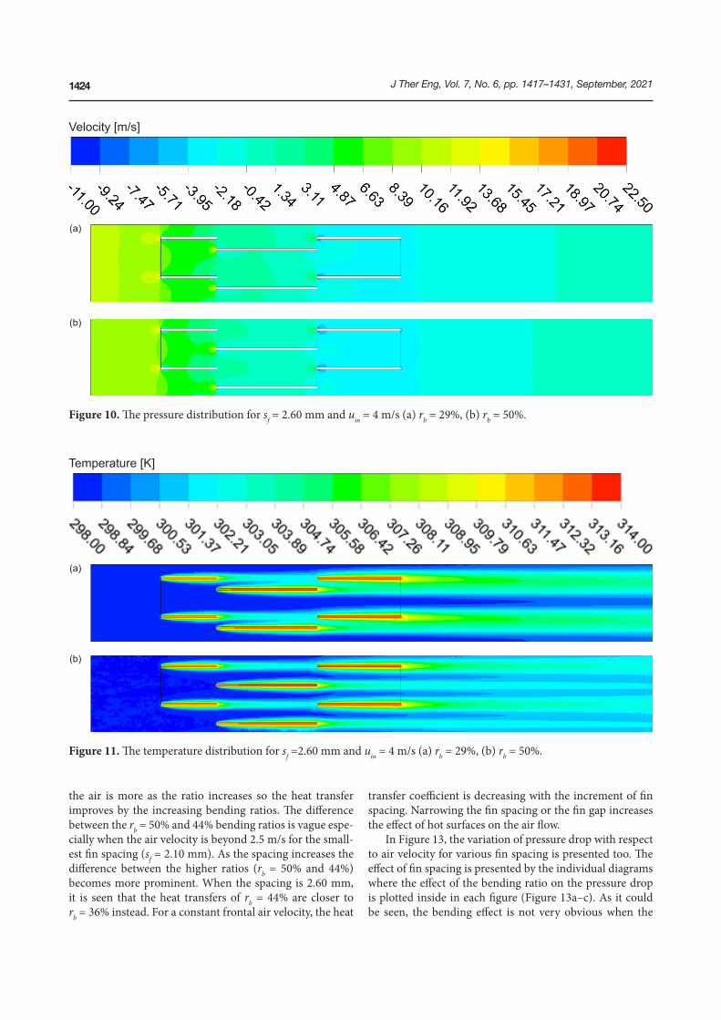
Figure 10. The pressure distribution for sf = 2.60 mm and uin = 4 m/s (a) rb = 29%, (b) rb = 50%.
Temperature [K]
(b)
(a)
Figure 11. The temperature distribution for sf =2.60 mm and uin = 4 m/s (a) rb = 29%, (b) rb = 50%.
the air is more as the ratio increases so the heat transfer improves by the increasing bending ratios. The difference between the rb = 50% and 44% bending ratios is vague espe-cially when the air velocity is beyond 2.5 m/s for the small-est fin spacing (sf = 2.10 mm). As the spacing increases the difference between the higher ratios (rb = 50% and 44%) becomes more prominent. When the spacing is 2.60 mm, it is seen that the heat transfers of rb = 44% are closer to rb = 36% instead. For a constant frontal air velocity, the heat
transfer coefficient is decreasing with the increment of fin spacing. Narrowing the fin spacing or the fin gap increases the effect of hot surfaces on the air flow.
In Figure 13, the variation of pressure drop with respect to air velocity for various fin spacing is presented too. The effect of fin spacing is presented by the individual diagrams where the effect of the bending ratio on the pressure drop is plotted inside in each figure (Figure 13a–c). As it could be seen, the bending effect is not very obvious when the

J Ther Eng, Vol. 7, No. 6, pp. 1417–1431, September, 2021 1425
The first one is the Colburn j-factor, the evolution of this parameter is plotted as regard to Re number. The j-factor falls in all calculated cases as the Re number ascends due to its definition which is given in Eq. (8). The change of the factor is almost the same in all three fin spacing’s (sf = 2.10, 2.35, and 2.60 mm). Even though the highest j-factor is observed when the fin spacing is small, the wider spac-ing does not affect that much and the heat transfer perfor-mance is slightly below range which is drawn in Figure 14a as the gap becomes bigger.
As for the effect of the bending ratio, the performance is higher when the bending ratio is more (rb = 50%). The fall of the bending ratio leads to a fall in the heat transfer as well.
pressure drop is the investigated case. Almost all bending ratio plots are overlapping in all three fin spacing’s (sf = 2.10, 2.35, and 2.60 mm). As the air velocity increases, the pressure drop ascends too, besides as the space between the fins becomes narrower, the pressure drop drives beyond 12 Pa range. The highest pressure drop is observed when the fin spacing is sf = 2.10 mm and it slightly falls apart the 12 Pa range as the fin spacing gets larger (sf = 2.60 mm). The major reason is the resistance against air flow decreases when the fin spacing increases.
The effect of fin spacing and fin bending on the perfor-mance is presented as regard to non-dimensional factors that are widely preferred in the field of heat exchangers.
a) sf =2.10 mm b) sf =2.35 mm
c) sf =2.60 mm
Figure 12. The variation of heat transfer coefficient with respect to frontal air velocity.

J Ther Eng, Vol. 7, No. 6, pp. 1417–1431, September, 20211426
a) sf = 2.10 mm b) sf = 2.35 mm
c) sf = 2.60 mm
Figure 13. The variation of pressure drop with respect to frontal air velocity.
The difference between varying ratios is more when the Re number is lower but it becomes less as Re number increases. The difference almost disappears as the Re approaches 1200. One other important effect, observed through the diagrams is the change by the fin spacing. As the spacing is smaller (sf = 2.10 mm), the highest two bending ratios (rb = 44% and 50%) resulted in closer factor values at lower Re number and the difference among them becomes prominent as the spacing increases (sf = 2.60 mm). All the findings of these particular calculations are in good agreement with the heat transfer coefficient change given previously.
The effect of the bending ratio and fin spacing on the friction factor f is demonstrated in Figure 15a-c. The impor-tance of the non-dimensional parameters is becoming more obvious in this figure sequence since the effect of bending couldn’t be observed in the pressure drop diagrams. The f factor descends in all cases too as in the previous one, the friction factor has a diminishing trend with respect to Reynolds number due to its definition given in Eq. (9).
The range of the f factor is higher for the narrower fin spacing (sf = 2.10 mm) than the wider ones (sf = 2.60 mm) as a consequence of the pressure drop values that are

J Ther Eng, Vol. 7, No. 6, pp. 1417–1431, September, 2021 1427
a) sf = 2.10 mm b) sf = 2.35 mm
c) sf = 2.60 mm
Figure 14. The variation of Colburn j-factor with respect to Reynolds number.
presented previously. As the gap becomes narrower with regard to increasing resistance the friction factor f becomes bigger. As it could be seen in the figures, as the bending ratio increases from rb = 29% to 50%, the f factor increases too, the difference is more noticeable at lower Re value which starts to overlap at the higher Re values. When the spacing is sf = 2.10 mm the difference between bending ratios rb = 44% and rb = 50% is less and somehow cross over each other, they separate from each other as the spacing increases (sf = 2.35 mm). Unfortunately, the effect of the bending ratio becomes less obvious again as the spacing turns to sf = 2.60 mm. The plots start to approach to each other, at higher Re values in particular.
One other performance measure used in the field of heat exchangers is the volume goodness factor j/f 1/3, as shown in Figure 16. It is widely preferred since it allows us to con-sider the j-factor and friction factor f at the same time which tends to have an idea about the overall performance of the components. The evolution of the volume goodness factor j/f 1/3 is presented with regard to bending ratios in three dif-ferent fin spacing individually. The range of the overall per-formance is not affected by the change of the spacing much with regard to the outcomes. The goodness factor falls as the Re number becomes higher in all cases. The effect of the bending ratio is more clear at wider fin gaps than the others. As regards to the plots, when the volume goodness

J Ther Eng, Vol. 7, No. 6, pp. 1417–1431, September, 20211428
a) sf = 2.10 mm b) sf = 2.35 mm
c) sf = 2.60 mm
Figure 15. The variation of friction factor with respect to Reynolds number.
factor is better when the bending is higher rb = 50% and it shows worse performance as the bending ratio is less rb = 29%. Among all the considered fin spacing, the fin bending ratio of rb = 50% gives the best performance. Similar to the j-factor and friction factor, the effect of the fin bending ratio is more considerable at low Reynolds numbers in terms of overall performance. The trend of the volume goodness fac-tor is changing between j/f1/3 = 0.04 and 0.83 for all consid-ered fin spacing.
CONCLUSION
In this study, the thermo-hydraulic performance of a heat exchanger with offset strip fin is analyzed numerically.
The combined effect of fin spacing and bending ratio in a narrow flow depth, which has not been reported before, will help the researchers for further investigations where the alternate designs are studied. The effect of the fin bend-ing ratio and the fin spacing over Reynolds numbers in the range of 200–1200 is determined and the results are pre-sented in terms of heat transfer coefficient, pressure drop, Colburn j-factor, friction factor f, and volume goodness factor. As regards the findings, when the bending ratio gets smaller, the flow becomes less interrupted which reduces the performance of the heat exchanger. In particular, it allows a free flow region in the investigated domain that decreases the performance more. Furthermore, as the spac-ing increases the impact of smaller bending ratios on the

J Ther Eng, Vol. 7, No. 6, pp. 1417–1431, September, 2021 1429
a) sf = 2.10 mm b) sf = 2.35 mm
c) sf = 2.60 mm
Figure 16. The variation of volume goodness factor with respect to Reynolds number.
performance becomes more which leads a worse efficiency. The outcomes that have to be highlighted at the end of the study can be listed as in the following:
• When uin = 1 m/s and sf = 2.10 mm, the heat transfer coefficient is increasing by about h = 58 Wm-2K-1 to 76 Wm-2K-1 for the fin bending ratio of rb = 29% and 50%, respectively. The effect of the fin bending ratio on the increasing trend of the heat transfer coefficient is decreasing when the frontal air velocity is increas-ing for all the fin spacing considered.
• The pressure drop is not affected significantly by the vari-ation of the fin bending ratio. The variation of pressure
drop with respect to the fin bending distance is in the range of 1.5–13 Pa for all the fin spacing considered.
• The Colburn j-factor gets its highest value at sf = 2.10 mm and ReDh = 235 in which the j-factor varies from 0.045 to 0.035 for the fin bending ratio of rb = 50% and 29%, respectively. This difference is almost disap-pearing at the higher Reynolds number.
• The effect of fin bending ratio on the j- and f factors is more dominant at low Reynolds number. When the Reynolds number is increasing, the effect of fin bend-ing ratio on the j- and f factors is almost disappearing. This phenomenon appears more prominently at sf = 2.60 mm.

J Ther Eng, Vol. 7, No. 6, pp. 1417–1431, September, 20211430
DATA AVAILABILITY STATEMENT
No new data were created in this study. The published publication includes all graphics collected or developed during the study.
CONFLICT OF INTEREST
The author declared no potential conflicts of interest with respect to the research, authorship, and/or publication of this article.
ETHICS
There are no ethical issues with the publication of this manuscript.
REFERENCES
[1] Doğan B, Erbay LB. Experimental analysis of the Effect of cold fluid inlet temperature on the thermal performance of a heat exchanger. Journal of Thermal Engineering 2015;2. [Crossref]
[2] Erbay LB, Doğan B, Öztürk MM. Comprehensive study of heat exchangers with louvered fins. In: Heat Exchangers - Advanced Features and Applications. London: IntechOpen; 2017. [Crossref]
[3] Sharma B, Bhushan G, Sachdeva G. Effect of flow structure on heat transfer in compact heat exchanger by using finite thickness winglet at acute angle. Journal of Thermal Engineering 2017;3:1149–49. [Crossref]
[4] Erdinç MT, Yılmaz T. Numerical ınvestigation of flow and heat transfer in communicating converg-ing and diverging channels. Journal of Thermal Engineering 2018;2318–32. [Crossref]
[5] Kays WM, London AL. Compact heat exchangers. 3rd ed. New York: McGraw-Hill; 1984.
[6] Saha SK, Ranjan H, Emani MS, Bharti AK. Offset-Strip Fins. In: Heat transfer enhancement in plate and fin extended surfaces. Springer Briefs in Applied Sciences and Technology; 2020, pp. 33–57. [Crossref]
[7] Zheng X, Qi Z. A comprehensive review of off-set strip fin and its applications. Applied Thermal Engineering 2018;139:61–75. [Crossref]
[8] Erbay LB, Öztürk MM, Doğan B. Comprehensive study of compact heat exchangers with offset strip fin. In: Heat Exchangers – Advanced Features and Applications. London: IntechOpen; 2017. [Crossref]
[9] Manson SV. Correlations of heat transfer data and of friction data for ınterrupted plane fins staggered in successive rows. Washington, DC, NACA Tech. Note 2237, 1950.
[10] Wieting AR. Empirical correlations for heat trans-fer and flow friction characteristics of rectangular offset-fin plate-fin heat exchangers. Journal of Heat Transfer 1975;97:488–90. [Crossref]
• The fin spacing has no significant effect on the vol-ume goodness factor while the rise of the fin bending ratio leads to an increase in the goodness factor.
ACKNOWLEDGMENT
This research was performed under the Santez Project (00888-STZ.2015). The authors would like to thank the Ministry of Science, Industry, and Technology and the Research and Development Department of the Arçelik A.Ş, Eskişehir Refrigerator Plant for their support.
NOMENCLATURE
Aa heat transfer area of air-side, m2
Ac minimum free-flow area, m2
Afr frontal area, m2 Cf fin bending distance, mmcp specific heat of air, kJ/(kgoC)Dh hydraulic diameter, mmf friction factorh heat transfer coefficient of air, W/(m2oC)hf fin height, mm j Colburn j-factork thermal conductivity, W/(moC)l total fin length, mmlf uninterrupted fin length, mmm mass flow rate of air, kg/sOSF Offset Strip FinP pressure, PaPr Prandtl numberQ heat transfer rate of air, WReDh Reynolds number of air siderb bending ratiosf fin spacing, mmTin inlet temperature of air, oCTout exit temperature of air, oCTw wall temperature of air, oCuc critical velocity, m/suin free flow velocity, m/s
Greek symbolsδf thickness of fin material, mmµ dynamic viscosity of the air, kg/msρ density of the air, kg/m3
AUTHORSHIP CONTRIBUTIONS
Concept: Dogan B., Ozturk M.M., Erbay L.B.; Design: Dogan B., Ozturk M.M., Erbay L.B.; Materials: Dogan B., Ozturk M.M., Erbay L.B.; Data: Dogan B., Ozturk M.M., Erbay L.B.; Analysis: Dogan B., Ozturk M.M., Erbay L.B.; Literature search: Dogan B., Ozturk M.M.; Writing: Dogan B., Ozturk M.M., Erbay L.B.; Critical revision: Dogan B., Ozturk M.M., Erbay L.B.

J Ther Eng, Vol. 7, No. 6, pp. 1417–1431, September, 2021 1431
[21] Fernández-Seara J, Diz R, Uhía FJ. Pressure drop and heat transfer characteristics of a titanium brazed plate-fin heat exchanger with offset strip fins. Applied Thermal Engineering 2013;51:502–11. [Crossref]
[22] Peng H, Ling X, Li J. Performance investigation of an innovative offset strip fin arrays in compact heat exchangers. Energy Conversion and Management 2014;80:287–97. [Crossref]
[23] Bhowmik H, Lee KS. Analysis of heat transfer and pressure drop characteristics in an offset strip fin heat exchanger. International Communications in Heat and Mass Transfer 2009;36:259–63. [Crossref]
[24] Sheik Ismail L, Ranganayakulu C, Shah RK. Numerical study of flow patterns of compact plate-fin heat exchangers and generation of design data for offset and wavy fins. International Journal of Heat and Mass Transfer 2009;52:3972–83. [Crossref]
[25] Karim ZAA, Azmi MNHM, Abdullah AS. Design of a heat exchanger for gas turbine inlet air using chilled water system. Energy Procedia 2012;14:1689–94. [Crossref]
[26] Peng H, Ling X. Numerical modeling and experi-mental verification of flow and heat transfer over serrated fins at low Reynolds number. Experimental Thermal and Fluid Science 2008;32:1039–48. [Crossref]
[27] Zhao N, Yang J, Li S, Wang Q. Numerical investi-gation of laminar thermal-hydraulic performance of Al2O3–water nanofluids in offset strip fins channel. International Communications in Heat and Mass Transfer 2016;75:42–51. [Crossref]
[28] Durmaz G. Experimental and numerical analysis of heat transfer performance of off-set strip fins. Izmir Institute of Technology, The Graduate School of Engineering and Science, 2009.
[29] Rahul VR, Kumar RA. Parametric study of heat transfer and pressure drop characteristics of a rect-angular offset strip fin compact heat exchanger. Chemical Engineering Transactions 2018;71:1381–86. [Crossref]
[11] Joshi HM, Webb RL. Heat transfer and friction in the offset stripfin heat exchanger. International Journal of Heat and Mass Transfer 1987;30:69–84. [Crossref]
[12] Mochizuki S, Yagi Y, Yang WJ. Transport phenom-ena in stacks of ınterrupted parallel-plate surfaces. experimental heat transfer. 1987;1:127–40. [Crossref]
[13] Manglik RM, Bergles AE. Heat transfer and pressure drop correlations for the rectangular offset strip fin compact heat exchanger. Experimental Thermal and Fluid Science 1995;10:171–80. [Crossref]
[14] Guo L, Chen J, Qin F, Chen Z, Zhang W. Empirical correlations for lubricant side heat transfer and fric-tion characteristics of the HPD type steel offset strip fins. International Communications in Heat and Mass Transfer 2008;35:251–62. [Crossref]
[15] Kim MS, Lee J, Yook SJ, Lee KS. Correlations and optimization of a heat exchanger with offset-strip fins. International Journal of Heat and Mass Transfer 2011;54:2073–79. [Crossref]
[16] Du J, Yang MN, Yang SF. Correlations and optimi-zation of a heat exchanger with offset fins by genetic algorithm combining orthogonal design. Applied Thermal Engineering 2016;107:1091–103. [Crossref]
[17] Dong J, Chen J, Chen Z, Zhou Y. Air-side thermal hydraulic performance of offset strip fin aluminum heat exchangers. Applied Thermal Engineering 2007;27:306–13. [Crossref]
[18] London AL, Shah RK. Offset rectangular plate-fin surfaces-heat transfer and flow friction character-istics. Journal of Engineering for Gas Turbines and Power 1968;90:218–28. [Crossref]
[19] Suzuki K, Hirai E, Miyake T, Sato T. Numerical and experimental studies on a two-dimensional model of an offset-strip-fin type compact heat exchanger used at low Reynolds number. International Journal of Heat and Mass Transfer 1985;28:823–36. [Crossref]
[20] Hu S, Herold KE. Prandtl number effect on offset fin heat exchanger performance: experimental results. International Journal of Heat and Mass Transfer 1995;38:1053–61. [Crossref]