numerical investigation of motion response of two …dcwan.sjtu.edu.cn/userfiles/numerical...
TRANSCRIPT

Procedia Engineering 116 ( 2015 ) 20 – 31
1877-7058 © 2015 Published by Elsevier Ltd. This is an open access article under the CC BY-NC-ND license (http://creativecommons.org/licenses/by-nc-nd/4.0/).Peer- Review under responsibility of organizing committee , IIT Madras , and International Steering Committee of APAC 2015doi: 10.1016/j.proeng.2015.08.260
ScienceDirectAvailable online at www.sciencedirect.com
8th International Conference on Asian and Pacific Coasts (APAC 2015)Department of Ocean Engineering, IIT Madras, India.
Numerical Investigation of Motion Response of Two Model Shipsin Regular Waves
Ruoshi Cha and Decheng Wan*
State Key Laboratory of Ocean Engineering, School of Naval Architecture, Ocean and Civil Engineering, Shanghai Jiao Tong University,Collaborative Innovation Center for Advanced Ship and Deep-Sea Exploration, Shanghai 200240, China
Abstract
In this paper, the sea keeping performances of two model ships in regular waves are studied by our in-house solver naoe-FOAM-SJTU based on OpenFOAM code package. Volume of Fluid (VOF) method is used to capture the free interface andFinite Volume Method (FVM) is adopted as the discretization scheme. Different wave conditions are set by the wavegeneration and damping module in the solver. The heave and pitch are simulated, and green water is found during the shipmotion. The function of bulbous bow for that is discussed.
© 2014 The Authors. Published by Elsevier B.V.Peer-review under responsibility of organizing committee of APAC 2015, Department of Ocean Engineering, IIT Madras.
Keywords: viscous-flow; ship motion response; regular waves; naoe-FOAM-SJTU solver
1. Introduction
The seakeeping feature is one important indicator of a ship’s hydrodynamic performance. When a ship is sailingin stormy waves, the ship motions with six DOFs bring about a series of problems, such as the added resistance,reduction of propelling efficiency, structure strength, stability and comfort quality. As a result, it has always been
* Corresponding author. Tel.: +86 21 34205697; fax: +86 21 34205685.E-mail address: [email protected]
© 2015 Published by Elsevier Ltd. This is an open access article under the CC BY-NC-ND license (http://creativecommons.org/licenses/by-nc-nd/4.0/).Peer- Review under responsibility of organizing committee , IIT Madras , and International Steering Committee of APAC 2015

21 Ruoshi Cha and Decheng Wan / Procedia Engineering 116 ( 2015 ) 20 – 31
of great concern of the ship designers and users. In this paper, the accurate prediction of ship motions to study theseakeeping performance and compare the influence of different hull forms is chosen as the main task.
Experimental method [1] is considered as the most precise way to study the seakeeping issue. However, therequirement on the devices and site and the high cost limit its application. In recent decades, a lot of studies arebased on potential flow theory, such as the Rankine source method [2] and ship strip theory [3]. ComputationalFluid Dynamics (CFD) method is also applied to solve related hydrodynamic problems frequently. The traditionalmethods using potential flow theory have advantages such as simplicity and high computational efficiency, whileCFD method is able to deal with the strong nonlinear factors caused by large amplitude motions, breaking freesurface and waves, with full consideration of flow velocity. Moreover, the application of CFD has benefited fromadvancing computer science and numerical methods. Especially the RANS (Reynolds-Averaged Navier-Stokes)simulation [4] has widely been used to compute the ship resistance and motion responses under various seaconditions.
Yang et al (2006) [5] used finite element method and unstructured-grid to simulate a LNG ship with liquid tankssailing in head and oblique waves. The coupled motion between the hull and tank with the inner and outer flowflied is considered about. Chengsheng Wu et al (2008) [6] built a numerical wave tank based on N-S method. Thestudy on the ship motion of a Wigley sailing in different wave conditions was conducted. Overset was also appliedto the computation of ship motion and added resistance of a catamaran in head waves by Castiglione et al (2011)[7]. Hamid et al (2013) [8] carried on the CFD verification and validation by simulating the added resistance andship motions of KVLCC2 sailing in short and long head waves using CFDShip-Iowa.
In this paper, RANS simulation was adopted to predict the ship motion in different wave conditions to study theseakeeping property of two special guard ships. Moreover, the motion responses of typical points on ship weresimulated. Compared with using commercial software directly, the independent development based on open sourcecode package is more flexible and extensible for multi-aspect issues. Based on OpenFOAM, the solver naoe-FOAM-SJTU [9] was used as the computational tool as its applicability for various kinds of complexhydrodynamic issues. On the foundation of original solver codes, a module for solving six DOFs motion equationswas added, along with deforming mesh technology and numerical wave generating&damping modules. Previouswork had made many progresses about developing and validating this solver applied in this paper. In 2011, ZhirongShen et.al [10] simulated the viscous flow acting on KVLCC2, KCS, and DTMB5415 and compared with themeasurement results by solver naoe-FOAM-SJTU. Haixuan Ye et.al (2012) [11] computed the added resistanceand vertical ship motions in regular head waves, and validated the ability of solver naoe-FOAM-SJTU to solve thestrong nonlinear problems.
2. Mathematic Model and Numerical Methods
2.1. Introduction to naoe-FOAM-SJTU solver
The incompressible RANS equations are applied in this paper as governing equations. The equation ofcontinuity and momentum equation can be written as Eqs. (1) and (2):
U 0 (1)U
( (U U )U ( U) ( U)d eff eff sp g x f ft σ
ρ ρ ρ μ μ (2)
eff = ( )tv vμ ρ (3)
Here, U stands for the velocity field while Ug means velocity of mesh nodes, pd is dynamic pressure. ismixture density of the two phases. g is the acceleration vector of gravity. In Eq. (3), μeff is the effective dynamicviscosity coefficient, where t is eddy viscosity coefficient. fσ is surfacetension term, which impacts the free surface. To protect the flow field from the interface of echo wave, the sourceterm fσ is added for sponge layer to absorb the generated wave [12].
The SST k ω model [13] is applied as the turbulence model in this paper. This turbulence model

22 Ruoshi Cha and Decheng Wan / Procedia Engineering 116 ( 2015 ) 20 – 31
synthesizes the advantages of standard k ω model and k ε model. The former one is appropriate to simulatethe turbulent flow far way the wall plane, while the other one is good at solve the boundary flow near the wallunder different pressure gradients. The application of SST k ω model would improve the accuracy of numericalcomputation results.
VOF (Volume of Fluid) method with artificial bounded compression technique is adopted for simulating freesurface in this paper. The VOF transport equation is formulated as below:
r[(U U ) ] [U (1 ) ] 0t
α α α α (4)
in which, α represents the volume of fraction, the relative proportion of the two phase fluid. The value of α is:=0 air
=1 water
0 1 interface
αα
α(5)
Moreover, the first two terms on the left hand side of Eq. (4) stand for traditional volume of fluid transportequation and the other term represents the artificial compression term. The term (1−α)α makes the compressionterm take effect only on the interface without affecting the numerical computation out of the transition layer. Ur isthe velocity field for compressing the interface. The velocity field can be computed at cell faces by the maximumvelocity magnitude at the interface region, defined as:
, S SU min ,max
f fr f fn C φ φ
α (6)
where is face volume flux, including the flux of grid velocities from the PISO algorithm; Cα is a compressioncoefficient indicating the degree of compression. It is set 1.0 in this paper based on previous experience. Thesmaller Cα is, the less enhanced the compression of the interface is. Cα=0 means no effect on interface while Cα =1leads to a conservative compression.
Finite Volume Method (FVM) is used to discretize both the RANS equations and VOF transport equation innaoe-FOAM-SJTU. Moreover, different interpolation schemes are applied. In detail, a second-order TVD limitedlinear scheme is used to discretize the convection terms in Eq. (2); the diffusion terms is discretized by a second-order central difference scheme; Van Leer scheme is applied for VOF equation discretization; A second-orderbackward method is applied for temporal discretization. For the discretized RANS equations with coupled pressureand velocity, PISO (pressure-implicit-split-operator) algorithm is adopted to solve the couple equation of velocityand pressure.
A complete 6DOF motion solver was developed for numerical computations to predict sinkage and trim ofship. The details of the solving processes can be obtained by related thesis. In naoe-FOAM-SJTU solver, twocoordinate systems are adopted to solve 6DOF equations including earth-fixed and ship-fixed coordinate system.The linear and angular velocity in two systems can be transformed by matrices. The shear stress and total pressurecan be calculated by the velocity field, and then the forces and moments in ship-fixed coordinate can be obtained.By rigid-body equations the linear and angular accelerations are educed. The velocity and motions can becalculated by integrating method. The dynamic deformation mesh is applied. The mesh topology would remainunchanged with the moving hull. By stretching and squeezing the cell shapes and changing the spacing betweennodes, the hull motions can be simulated well. The location of grid nodes in the flow field can be solved accordingto the Laplace equation:
) 0gxγ (7)
in which, xg is the node’s displacement and means the diffusivity coefficient. In this paper, the value of can bedetermined as:
2
1
rγ (8)
thereinto, r stands for the distance between cell center and hull surface. The deformation of the grids near the hullsurface would be small enough to ensure the high quality of the mesh around the hull.

23 Ruoshi Cha and Decheng Wan / Procedia Engineering 116 ( 2015 ) 20 – 31
In addition, the solver also includes both wave generation and damping modules [14]. They have been used inpast studies maturely. Different conditions of linear regular wave can be simulated in this numerical tank. In thispaper, the first order stoke wave in deep water is adopted and the sponge layer is used as the damping area after thehull stern in the flow field.
2.2. Fourier series analysis and transfer function
According to the periodicity of the force and motion responses, Fourier series analysis has been widelyapplied to the CFD analysis of seakeeping performance. The Fourier series of any time-dependent variable φ(t) canbe written as:
0
n 1
t = + cos( ), 1, 2,...2
N
n e nn t nϕϕ ϕ ω γ (9)
2 2 1, tan ( )nn n n n
n
ba b
aϕ γ (10)
T T
0 0
2 2( ) cos( ) , ( ) sin( )n e n ea t w nt dt b t w nt dt
T Tϕ ϕ (11)
The subscript n means the order of different responses. In Eq. (9) and (10), the parameter φn stands for themotion amplitude while γn represents for the phase. The amplitude with n=1 indicates the linear component of thevariable, while the terms with n≥1 reflect the nonlinear extent. They can be computed in accordance with Eq. (11).Generally, the nonlinear terms are considered as n = 2 because the higher order terms are small quantities whichcan be neglected.
In addition, the method of Transfer Function is applied to analyze the frequency response of each motion. Thetransfer functions of heave and pitch is defined as:
1 13 53 5,
x xTF TF
a ak(12)
The subscript 3 means the third DOF of hull motion namely heave, while 5 means the fifth DOF of hullmotion namely pitch. The numerator stands for the first order amplitude of the Fourier series of each motionresponse; a means the amplitude of incident wave and k means the wave number.
2.3. The simulation of vorticity field
In this paper, the tensor invariant Q is used to indicate the vorticity field [15]. The velocity field of threedimensions can be indicated as:
u i ij jA x (13)
where the Aij is the velocity gradient tensor. Q can be written as:
21
( )2 ij ji ij jiQ P S S W W (14)
in which, Sij is the rate of strain tensor and Wij is the rate of rotation tensor. These parameters are defined as:
,2 2
ii
ij ji ij jiij ij
P A
A A A AS W
(15)
The vorticity field of three dimensions and its change can be clearly shown by the distribution of Q according tothe velocity field.

24 Ruoshi Cha and Decheng Wan / Procedia Engineering 116 ( 2015 ) 20 – 31
3. Mathematic Model and Numerical Methods
3.1. 3.1. Hull model
The main dimensions and particulars of the two patrol ships are shown in Table Error! No text of specified stylein document.-1. The related data of full scale ships are set in the columns of Hull 1 and Hull 2. The model scale ofthe two patrol ships are chosen for the numerical computation in this paper. Compared with the full scale, the maindimensions and particulars of model scale are set in the columns of Model 1 and Model 2. The 3D models aredisplayed and compared in Error! Reference source not found., including the details of both bow and stern. Inparticular, the size and location of the bulbous bow of model 2 are shown clearly.
Table Error! No text of specified style in document.-1 Main dimensions and particulars
Main Features Symbol Hull 1 Hull 2 Model 1 Model 2
Scale ratio λ 30.270 30.270 1.000 1.000
Length between perpendiculars Lpp (m) 90.800 90.800 3.000 3.000
Length of waterline Lwl (m) 94.000 94.000 3.106 3.106
Breadth B (m) 12.200 12.200 0.403 0.403
Draught d (m) 3.400 3.400 0.112 0.112
Block Coefficient CB 0.486 0.504 0.486 0.504
Wetted surface S (m2) 1079.130 1119.400 1.178 1.222
Longitudinal center of gravity LCG (m) 48.620 48.620 1.606 1.606
Vertical center of gravity KG (m) 1.810 1.810 0.060 0.060
Longitudinal inertia radius Kyy / Lwl 0.230 0.230 0.230 0.230
Transverse inertia radius Kxx / B 0.380 0.380 0.380 0.380
Vertical inertia radius Kzz / Lwl 0.230 0.230 0.230 0.230
Vertical inertia moment Izz (kg m2) 7.98×10⁸ 7.98×10⁸ 31.359 31.359
Longitudinal inertia moment Iyy (kg m2) 7.98×10⁸ 7.98×10⁸ 31.359 31.359
Transverse inertia moment Ixx (kg m2) 3.93×10⁷ 3.93×10⁷ 1.545 1.545
According to the 6-DOF motion simulation module of naoe-FOAM-SJTU, two coordinate systems are built forsolving the motion equations, as what mentioned before. In Table 3 1, the longitudinal or vertical center of gravityis calculated in the earth-fixed system, while all of the inertia radius and moment are calculated in the ship-fixedcoordinate system.
By comparing the two ships, it can be found that the main dimensions of them are identical except the blockcoefficient and the wetted surface area. The main differences of them are bow shape and arrangement. Model 1adopts the raked bow rather than the bulbous bow which is applied to model 2. Moreover, the structure of bulwarkis only equipped on model 1. These characteristic differences lead to the unlike seakeeping performance of eachhull.
3.2. Case conditions
Two conditions are considered in this paper, including the different wave states and sailing velocityconditions. As shown in Table Error! No text of specified style in document.-2, V stands for the sailing velocity of thehull in model scale, which corresponds to 22kn and 18kn of the hull in full scale. h means the wave height;

25 Ruoshi Cha and Decheng Wan / Procedia Engineering 116 ( 2015 ) 20 – 31
means the wave length; ak is the wave steepness, in which a represents for the wave amplitude and k stands for thewave number. The column of Motion shows the unfixed DOFs of the hull motion. Under the conditions of sailingin head waves, pitch and heave should be considered, because the trim and sinkage of the hull have a significantinfluence on the resistance and seakeeping performance. Te means the period of encounter in the ship-fixedcoordinate system, calculated as,
021/ ( )
2ee
U gT
w
πλ πλ
(16)
For all of the cases in this paper, the regular cosine wave is set as the flow condition. At the beginning ofcalculation, the hull is under upright condition and the X-Y plane is set as the water plane. Due to the workingcondition of these ships, the liquid density is set 1024 kg/m3 as the sea-water density of 20
Table Error! No text of specified style in document.-2 Wave and sailing conditions
case model V (m/s) Fr Re h (m) (m) ak motion Te (s)
1 model 1 1.683 0.31 4.79×10⁶ 0.1652 2.21 0.235 pitch, heave 0.62502 model 1 2.057 0.38 5.86×10⁶ 0.1320 4.50 0.092 pitch, heave 0.95593 model 2 2.057 0.38 5.86×10⁶ 0.1320 4.50 0.092 pitch, heave 0.95594 model 2 1.683 0.31 4.79×10⁶ 0.1652 2.21 0.235 pitch, heave 0.6250
4. Computational Domain and Mesh Generations
Due to the symmetrical structure of hull by X-Z plane, a half of the flow field with a half hull can be used asthe computational domain. The motion response of the half hull is the same as the actual integrated ship. As aresult, it helps reduce the amount of computations and improve the efficiency.
SnappyHexMesh, the mesh generation utility of OpenFOAM is used to create the mesh in this paper. Firstly, astructural background mesh with hexahedral grid is generated. Then the homogeneous grid is divided into theoctree structure by SnappyHexMesh. The boundary mesh is added near the hull surface in order to simulate thecomplex flow in the boundary layer of the hull. In this paper the meshes of all four cases are generated by the samesize and setting. In the earth-fixed coordinate system, the computational domain is determined as -1.0Lpp<x<3.0Lpp,0<y<1.0Lpp, -1.0Lpp<z<1.0Lpp. The mesh details of model 1 and model 2 are displayed in Figure Error! No text ofspecified style in document.-1, along with the overall view of the domain.

26 Ruoshi Cha and Decheng Wan / Procedia Engineering 116 ( 2015 ) 20 – 31
Figure Error! No text of specified style in document.-1 Mesh generation
As shown in Figure 4-1(a), the interface grids are refined to better simulate the free surface and wave-makingsituation. Furthermore, the refinement regions also cover the boundary layer of the hull, the region near the bowand stern structure, and the region consists of a big variation of curvature and skewness. It is necessary to refine theimportant region so that a higher accuracy of the numerical computation can be achieved. The number of cell ofthe computational mesh is about 1.23×10⁶.
5. Results Analysis
5.1. The pitch and heave of two hulls
After amounts of time steps, it can be found that the motion responses have cyclical fluctuations. In the earth-fixed coordinate system, the pitch and heave variation with time are shown in Figure Error! No text of specified stylein document.-2. The horizontal axis is the dimensionless time duration. The vertical axis is the motion amplitude.The positive result of pitch stands for trim by the stern while the positive result of heave represents for the motionforward the positive direction of Z-axis.
(a) Hull 1 (b) Hull 2
Figure Error! No text of specified style in document.-2 Time histories of pitch and heave response
From Figure Error! No text of specified style in document.-2, for all of the cases, the duration curves of pitchare regular sinusoid or cosinusoid, showing the obvious linear characteristic of these responses. The non-linear component cannot be observed. The response amplitude of small wave steepness equaling to 0.092 islarger than that of big wave steepness equaling to 0.235. It is inferred that the influence of velocity is beyondthat of wave intensity of the conditions in this paper. The increase of ship velocity of Froude number from0.31 to 0.38 makes the hull pitch change much more heavily. In addition, the regularity of heave is just thesame as pitch of the different conditions.

27 Ruoshi Cha and Decheng Wan / Procedia Engineering 116 ( 2015 ) 20 – 31
For quantity analysis, the Fourier series expansion method is adopted to process the data of pitch andheave. The zero order amplitude of pitch or heave stands for the value of time-average. The first orderamplitude means the linear intensity, while the second order is the greatest nonlinear intensity which can beused to represent the nonlinear intensity. Due to the slight influence of the responses above second order,these high order terms can be ignored. The zero, first and second order of amplitude and phase are concernedin this paper, which are shown in Table Error! No text of specified style in document.-3.
Table Error! No text of specified style in document.-3 Motion responses via FS expansions
Hull No. Motion ak0th 1st 2nd
amp. (m) amp. (m) phase (deg) amp. (m) phase (deg)
hull 1
heave0.092 -0.0053 0.0552 -127.8 0.0010 -9.6
0.235 -0.0073 0.0130 72.0 0.0011 170.7
pitch0.092 0.67 4.96 -71.5 0.16 37.6
0.235 -0.57 1.20 98.5 0.10 -164.2
hull 2
heave0.092 -0.0045 0.0550 -126.1 0.0011 22.4
0.235 -0.0037 0.0149 73.6 0.0012 163.4
pitch0.092 0.75 5.05 -71.0 0.15 49.3
0.235 -0.35 1.26 97.1 0.10 -167.1
As shown in Table Error! No text of specified style in document.-3, the 0th and 2nd harmonic amplitudes ofboth heave and pitch motions are similar of these conditions. Their values are all smaller than the 1st
harmonic components. It indicates that the linearity plays the main role in the motion response. For bothhulls, the 1st harmonic amplitudes of heave and pitch are reduced under the combined action of increasingwave steepness and decreasing of velocity. Also the change of phase of the 1st harmonic components is moreor less as . The velocity augment help improve the nonlinearity of the motion response of both hulls.Furthermore, comparing hull 1 wit hull 2, the time average value of the pitch of hull 2 is larger than that ofhull 1 when ak=0.092. However, when ak=0.235, the time average value of the pitch of hull 2 becomessmaller than that of hull 1. It means that the bulbous bow has a damping function on the pitch motion onlyunder special conditions.
To better analyze the motion responses, the method of Transfer Function is used in this paper. TF3 standsfor the transfer function of heave and TF5 represents for the transfer function of pitch. According to Eq. (12),the calculation result is listed in Table Error! No text of specified style in document.-4.
Table Error! No text of specified style in document.-4 Transfer function of the heave and pitch
Hull No. λ/L TF3 TF5
hull 10.74 0.157 5.123
1.50 0.836 53.913
hull 20.74 0.180 5.348
1.50 0.833 54.867
In Table Error! No text of specified style in document.-4, for the wave condition of λ/L equaling to 1.5, thetransfer functions of both heave and pitch are larger than that of λ/L equaling to 0.74. It can be inferredthat when λ/L =1.5, the encounter frequency is closer to the natural frequency of both hulls. As a result,it brings about a more intensive hull motion. The difference of the bow form has less impact on thenatural frequency and the body motion.

28 Ruoshi Cha and Decheng Wan / Procedia Engineering 116 ( 2015 ) 20 – 31
5.2. The motion response of typical locations
In this paper, three typical locations are studied to discuss the seakeeping of hulls in head waveconditions, including the center of gravity, the control room and the helicopter lifting platform. Thecoordinates of corresponding point of the typical locations are provided in Table Error! No text of specified stylein document.-5. For more convenient comparison, the dimensionless terms including time t’, relativedisplacement ’, velocity U’ and acceleration a’ are gained by the Eq. (17).
2' , ' , ' , '
e e e
t U at U a
T h h h
δδω ω
(1)
in which, Te is the period of encounter; h stands for the wave height; e is the frequency of encounter. Due tothe similar regular patterns, only one case is displayed here. For instance, the motion response case 1 isshown in Figure Error! No text of specified style in document.-3.
Table Error! No text of specified style in document.-5 Coordinate in ship-fixed coordinate system of typical points
Figure Error! No text of specified style in document.-3 The motion response of typical points of case 1

29 Ruoshi Cha and Decheng Wan / Procedia Engineering 116 ( 2015 ) 20 – 31
Four complete periods of the motion response have been shown in Figure Error! No text of specified style indocument.-3. Due to the only two unfixed motion degrees of freedom of pitch and heave, the center of gravityonly have the motion response in Z direction. While the points of control room and helicopter lifting platformhave two motion responses in X direction and Z direction respectively. The control room is at the fore part ofthis hull and on the contrary, the helicopter lifting platform is at the aft part of this hull. With the action ofwave motion, the relative displacement, velocity and acceleration in each direction have changed regularlyand periodically.
For all of the cases, if the relative displacement in a certain direction is equal to zero, it means that thispoint has returned to its initial location in this direction. The positive value of each motion response standsfor the motion vector is along the positive direction of that axis. For the center of gravity, the change of ’ isthe same as the heave motion response of whole hull. The amplitude of ’, velocity U’ and acceleration a’can reflect the intensity of wave condition. As a result, the response amplitude of case 2 and case 3 is smallerthan case 1 and case 4. In addition, the acceleration response of helicopter lifting platform in X direction isnot a regular sine or cosine curve, which illustrates the intensive nonlinear motion of the motion.
5.3. Free surface
The simulation of free surface is an ignorable aspect to study the seakeeping performance of the twoships in this paper. Some strong nonlinear phenomena can be observed.
In order to show the different wave patterns at different moments, the graphics of the free surface at fourtypical moments in one period are displayed. The moments including t/T=0, 0.25, 0.50, 0.75. Take case 1 forexample as shown in Figure Error! No text of specified style in document.-4.
Figure Error! No text of specified style in document.-4 The free surface of hull 1 in one period (fn=0.31)
The free surface of case 1 is well shown in Figure Error! No text of specified style in document.-4. With thefunction of the regular wave, the heave motion of the hull can be obviously observed by the freeboard heightat bow. Meanwhile the change of trim angle reflects the pitch motion of the hull. Some intensive nonlinearphenomenon can be simulated when the wave passes the hull surface. For instance, in Figure Error! No text ofspecified style in document.-4(b), the wave breaking of the heavy wave crest at bow was found. The hull
30 Ruoshi Cha and Decheng Wan / Procedia Engineering 116 ( 2015 ) 20 – 31
wetness would grow heavily. If it is sailing under a sea condition of higher level, the phenomenon of greenwater and slamming may happen, which is bad for the resistance and seakeeping performance. In addition,from these four graphics, the wake field after the stern is also displayed. Apparent wave trough and crest aregenerated, spread from the stern to far field.
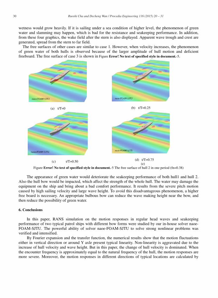
The free surfaces of other cases are similar to case 1. However, when velocity increases, the phenomenonof green water of both hulls is observed because of the larger amplitude of hull motion and deficientfreeboard. The free surface of case 3 is shown in Figure Error! No text of specified style in document.-5.
(a) t/T=0 (b) t/T=0.25
(c) t/T=0.50 (d) t/T=0.75(e)
Figure Error! No text of specified style in document.-5 The free surface of hull 2 in one period (fn=0.38)
The appearance of green water would deteriorate the seakeeping performance of both hull1 and hull 2.Also the hull bow would be impacted, which affect the strength of the whole hull. The water may damage theequipment on the ship and bring about a bad comfort performance. It results from the severe pitch motioncaused by high sailing velocity and large wave height. To avoid this disadvantageous phenomenon, a higherfree board is necessary. An appropriate bulbous bow can reduce the wave making height near the bow, andthen reduce the possibility of green water.
6. Conclusions
In this paper, RANS simulation on the motion responses in regular head waves and seakeepingperformance of two typical patrol ships with different bow forms were studied by our in-house solver naoe-FOAM-SJTU. The powerful ability of solver naoe-FOAM-SJTU to solve strong nonlinear problems wasverified and intensified.
By Fourier expansion and the transfer function, the numerical results show that the motion fluctuationseither in vertical direction or around Y axle present typical linearity. Non-linearity is aggravated due to theincrease of hull velocity and wave height. But in this paper, the change of hull velocity is dominated. Whenthe encounter frequency is approximately equal to the natural frequency of the hull, the motion responses aremore severe. Moreover, the motion responses in different directions of typical locations are calculated by

31 Ruoshi Cha and Decheng Wan / Procedia Engineering 116 ( 2015 ) 20 – 31
rigid-body motion equations. These motions with time durations are obtained. The motion of control roomhas a larger variation in X direction, and the motions of helicopter lifting platform are relatively small, whichis conductive to the operation of helicopter.
The free surfaces of two hulls were captured to show the seakeeping performance. Unfortunately whensailing in high speed, the green water and wave breaking should never be ignored. In this paper these strongnonlinear phenomena can be simulated and observed for both hull 1 and hull 2.Furthermore, the vorticityfields were shown well, especially at the location of bow and stern. It brings about the strenuous vibrationand makes seakeeping performance worse.
Finally, the comparison between hull 1 without bulbous bow and hull 2 with bulbous bow showed that, thedesign of bulbous of hull 2 did not help to improve the seakeeping performance well. The motion responsesseem to be limited affected by the bow shape at least under the conditions in this paper. And when sailing athigh speed, the green water and wave breaking also took place for both two hulls. It is not sure that thebulbous bow would damp the motion and the height of wave generation under other conditions. It is foundedthat the bulbous bow certainly can help improve the seakeeping performance, but the effect is limited bywave condition and other factors such as the location and size of bulbous bow, which should be consideredcomprehensively. As a result, more studies should be carried on.
Acknowledgements
This work is supported by National Natural Science Foundation of China (Grant Nos. 51379125, 51490675,11432009, 51411130131), The National Key Basic Research Development Plan (973 Plan) Project of China (GrantNo. 2013CB036103), High Technology of Marine Research Project of The Ministry of Industry and InformationTechnology of China, Changjiang Scholar Program of China (Grant No. 2014099) and the Program for Professorof Special Appointment (Eastern Scholar) at Shanghai Institutions of Higher Learning(Grant No. 2013022), towhich the authors are most grateful.
References
[1] Yang J, Xiao L, Peng T, et al. Investigation of motions of an oil tanker model in shallow water with irregular waves[J]. The oceanengineering/Haiyang Gongcheng. Shanghai, 2000, 18(3): 25-29. (in Chinese)
[2] Nakos D, Sclavounos P. Ship motions by a three-dimensional Rankine panel method[J]. 1991.[3] Xia J, Wang Z, Jensen J J. Non-linear wave loads and ship responses by a time-domain strip theory[J]. Marine Structures, 1998, 11(3): 101-
123.[4] Wilson R V, Stern F, Coleman H W, et al. Comprehensive approach to verification and validation of CFD simulations. 2: Application for
RANS simulation of a cargo/container ship[J]. Journal of fluids engineering, 2001, 123(4): 803-810.[5] Yang C, Löhner R, Lu H. An unstructured-grid based volume-of-fluid method for extreme wave and freely-floating structure interactions[J].
Journal of Hydrodynamics, Ser. B, 2006, 18(3): 415-422.[6] Wu C, Zhu D, Gu M. Computation of hydrodynamic forces for a ship in regular heading waves by a viscous numerical wave tank[J].
Journal of Ship Mechanics, 2008, 12(2): 168. (in Chinese)[7] Castiglione T, Stern F, Bova S, et al. Numerical investigation of the seakeeping behavior of a catamaran advancing in regular head
waves[J]. Ocean Engineering, 2011, 38(16): 1806-1822.[8] Sadat-Hosseini H, Wu P C, Carrica P M, et al. CFD verification and validation of added resistance and motions of KVLCC2 with fixed and
free surge in short and long head waves[J]. Ocean Engineering, 2013, 59: 240-273.[9] Shen Z R, Cao H J, Wan D C. Manual of CFD solver naoe-FOAM-SJTU[R]. Shanghai Jiaotong University, Shanghai, China, 2012.[10] Shen Z R, Jiang L, MIAO S. RANS simulations of benchmark ships based on open source code[C]//Proceedings of the Seventh
International Workshop on Ship Hydrodynamics (IWSH’2011), Shanghai, China. 2011.[11] Ye H, Shen Z, Wan D C. Numerical prediction of added resistance and vertical ship motions in regular head waves[J]. Journal of Marine
Science and Application, 2012, 11(4): 410-416.[12] Shen Z R, Wan D C. RANS computations of added resistance and motions of ship in head waves[C]//Proceedings of Twenty-second
(2012) Ocean (Offshore) and Polar Engineering Conference, Rhodes, Greece, ISOPE. 2012.[13] Menter F R. Improved two-equation k-omega turbulence models for aerodynamic flows[J]. NASA STI/Recon Technical Report N, 1992,
93: 22809.[14] Cha J J, Wan D C. Numerical wave generation and absorption based on OpenFOAM [J]. Ocean Engineering (Haiyang Gongcheng), 2011,
29(3): 1-12.(in Chinese)[15] Chong M S, Perry A E, Cantwell B J. A general classification of three-dimensional flow fields[J]. Physics of Fluids, 1990, 2: 408-420.