numerical investigation of the performance of an acc
TRANSCRIPT

Numerical Investigation of the Performance of an ACC Presenter: RA Engelbrecht
Academic Mentor: Prof. S.J. van der Spuy
Industrial Mentor: AF Du Preez
Date: 11/12 July 2016

2
Outline
• Project Background
• Model Implementation & Validation
• Future/Planned Research

• Recirculation at periphery fans
• Effects of buildings
• Effects on fan volume flow and performance
Fan Flow Effects
3
• Separation Effects

Study Objectives
• Objectives
• Implement axial flow fan and A frame heat exchanger model
• Validate Models
• Determine operating points
• Model 30 fan ACC bank with different fan configurations and different environmental effects
• Outcomes
• Determine effect of environmental conditions on performance of ACC through power requirements
4

Axial Flow Fan Model
• Actuator Disk Model (ADM) developed by Thiart and von Backström (1993)
• Implemented in Open source Field Operation and Manipulation (OpenFOAM) software package
• Blade element theory
• Uniform disk grid spacing
5

Axial Flow Fan Model
• Actuator Disk Model was chosen for:
Accurate flow representation downstream of fan
Power can be measured
OpenFOAM implementation
• Two fans used in this study
6
Fan
Designation
Fan Diameter
(m)
Hub-to-tip
Ratio
No. of Blades
A Fan 9.145 0.153 8
B2 Fan (small) 1.542 0.4 8

ADM Validation
• BS848 Type-A test facility at Stellenbosch
• Computational Domain
7

ADM Validation
• Performance Characteristics
• Static Pressure vs. Flow Rate
8
-10
40
90
140
190
240
290
340
390
440
490
0 5 10 15 20 25
Sta
tic
Pre
ss
ure
[P
a]
Volumetric Flow Rate [m3/s]
ADM Analysis
Experimental
B2-Fan: 8 bladed
Diameter: dF = 1.542 m
Blade Angle (chord line): cr = 31o
Density: a = 1.2 kg/m3
Speed: N = 750 rpm

ADM Validation
• Performance Characteristics
• Power vs. Flow Rate
9
0
1000
2000
3000
4000
5000
6000
0 5 10 15 20 25
Po
we
r [W
]
Volumetric Flow Rate [m3/s]
ADM Analysis
Experimental
B2-Fan: 8 bladed
Diameter: dF = 1.542 m
Blade Angle (chord line): cr = 31o
Density: a = 1.2 kg/m3
Speed: N = 750 rpm
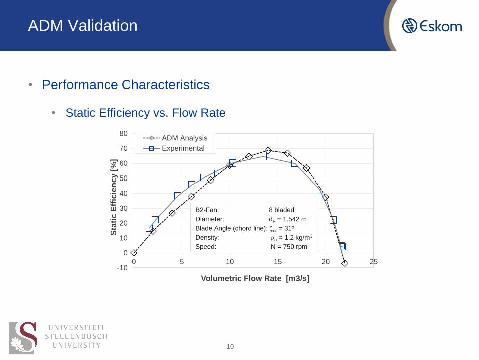
ADM Validation
• Performance Characteristics
• Static Efficiency vs. Flow Rate
10
-10
0
10
20
30
40
50
60
70
80
0 5 10 15 20 25
Sta
tic
Eff
icie
nc
y [
%]
Volumetric Flow Rate [m3/s]
ADM Analysis
Experimental
B2-Fan: 8 bladed
Diameter: dF = 1.542 m
Blade Angle (chord line): cr = 31o
Density: a = 1.2 kg/m3
Speed: N = 750 rpm

Heat Exchanger Model
• Heat Exchanger Models
• Elliptical, double row finned tubes
11
Designation Loss Parameter Heat Transfer (1st Row) Heat Transfer (2nd Row)
Finned
Elliptical Tube
Khe = 4464.831Ry-0.439275 Ny(1) = 583.8307Ry0.4031 Ny(2) = 1277.72Ry0.3806

• Pressure Drop
• One Dimensional Draft Equation without fan pressure recovery term
𝑝𝑎1 − 𝑝𝑎7 ≈ 𝐾𝑡𝑠1
2𝜌𝑎1
𝑚𝑎
𝑛𝑏𝐴𝑓𝑟
2
+ 𝐾𝑢𝑝 + 𝐾𝑑𝑜1
2𝜌𝑎3
𝑚𝑎
𝐴𝑒
2 + 𝐾𝜃𝑡
1
2𝜌𝑎56
𝑚𝑎
𝑛𝑏𝐴𝑓𝑟
2
• Flow Conditioning
• Darcy-Forccheimer Porous Medium
𝐹𝑖 = − 𝐶𝑖1
2𝜌 𝑣 𝑣𝑖 +
𝜇𝑖
𝛼𝑣𝑖
• Heat Transfer
• 𝛆-NTU
𝑄(𝑖) = 𝑚𝑎𝑐𝑝𝑎 𝑇𝑎𝑜 𝑖 − 𝑇𝑎𝑖 𝑖 = 𝑒 𝑖 𝑚𝑎𝑐𝑝𝑎(𝑇𝑠 − 𝑇𝑎𝑖 𝑖 )
Heat Exchanger Model
12

Heat Exchanger Model Validation
• Heat Transfer
• Pressure Drop
13
315
319
323
327
331
335
0 200 400 600 800 1000
Ou
tlet
Tem
pera
ture
[K
]
Volumetric Flow Rate [m3/s]
Analytical Solution
Numerical Results
0
100
200
300
400
500
600
0 200 400 600 800 1000
Pre
ssu
re D
rop
[P
a]
Volumetric Flow Rate [m3/s]
Analytical Solution
Numerical Results
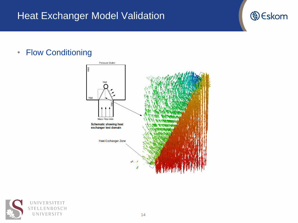
Heat Exchanger Model Validation
• Flow Conditioning
14

• Computational Domain
• Operating Point
Operating Point
15
Fan Designation Analytical (m3/s) Numerical (m3/s) Power (W)
A Fan
631.1685
620.193 207 814
B2 Fan 625.923 203 281

Operating Point
• A Fan
16
• B2 Fan

30 Fan ACC Bank
• Generic ACC with B2 Fans for validation
• Validation will be done by comparing the volumetric effectiveness to previous literature
𝑉𝑒𝑓𝑓 = 𝑉/𝑉𝑖𝑑
• Different fan configurations will be tested under differing environmental conditions to determine the effect on power output of the bank
17

Thank you