numerical investigation of wind-tunnel model deformations ... · transonic windtunnel. the same...
TRANSCRIPT
Engineering NotesNumerical Investigation of Wind-Tunnel
Model Deformations Caused by the
Twin-Sting Support System
Roberto Flores,∗ Enrique Ortega,† and Eugenio Oñate‡
International Center for Numerical Methods in Engineering,
Universidad Politécnica de Cataluña,
08034 Barcelona, Spain
DOI: 10.2514/1.45272
I. Introduction
T HE present work is part of a broader investigation aimed atimproving the understanding of the aerodynamics of the rear
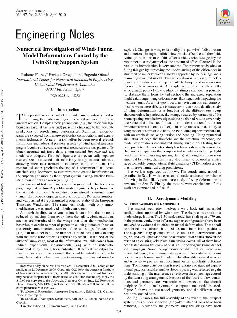
aircraft section. Complex flow phenomena (e.g., the thick fuselageboundary layer at the rear end) present a challenge to the accuratepredictions of aerodynamic performance. Significant efficiencygains are expected from improved-fidelity computations and experi-mental techniques. As part of a joint effort between several researchinstitutions and industrial partners, a series of wind-tunnel test cam-paigns focusing on accurate rear-end measurements was planned. Toobtain accurate tail-force data, a nonstandard live-rear-end testmodel was adopted. This technique uses a mechanically separaterear-end section attached to themain body through internal balances,allowing direct measurement of the force acting on the tail. Thismechanical setup precludes the use of a conventional tail-cone-attached sting. Moreover, to minimize aerodynamic interference onthe empennage caused by the support system, a wing-attached twin-sting mounting was chosen (see Fig. 1).
Two series of test campaigns were programmed. The first cam-paign targeted the low-Reynolds-number regime to be performed atthe Aircraft Research Association conventional transonic windtunnel. The second campaign aimed at true cruise Reynolds numbersandwas planned at the pressurized cryogenic facility of the EuropeanTransonic Windtunnel. The same test model, with only minormodifications, was employed in both campaigns.
Although the direct aerodynamic interference from the booms isreduced by moving them away from the tail section, additionalstresses are introduced in the wings that alter their mechanicalbehavior. A certain number of papers in existing literature focus onthe aerodynamic interference effect of the twin stings: for example,[1,2]. On the other hand, the number of published studies dealingwith the aeroelastic effects is surprisingly small. To the best of theauthors’ knowledge, most of the information available comes fromindirect experimental measurements [3,4], with no systematicnumerical study having been published. If accurate aerodynamicmeasurements are to be obtained, the possible perturbations due towing deformation when using the twin-sting arrangement must be
explored.Changes inwing twist modify the spanwise lift distributionand therefore, through modified downwash, affect the tail flowfield.Although the importance of this effect iswidely acknowledged by theexperimental aerodynamicists, the amount of effort allocated in thepast to its investigation is very modest. The present study aims atfilling this gap by improving the understanding of the differences instructural behavior between a model supported by the fuselage and atwin-sting mounted model. This information is necessary to deter-mine the limitations of the experimental technique and increase con-fidence in themeasurements. Although it is desirable from the strictlyaerodynamic point of view to place the stings as far apart as possible(to distance them from the tail section), the increased separationmight entail larger wing deformations, thus negatively impacting themeasurements. As a first step toward achieving an optimal compro-mise between these effects, it is necessary to carry out a detailed studyof wing deformations as a function of the different test setupcharacteristics. In particular, the changes caused by variations of theboom spacing must be investigated (the published results cover onlyone value of the distance for each test model and therefore do notprovide information on its effect). This Note focuses on the study ofwing model deformation due to the twin-sting support mechanism,with an emphasis on wing torsion and bending. Using numericalsimulation of both the flowfield and the structural response, themodel deformations encountered during wind-tunnel testing havebeen predicted. A parametric study has been performed to assess thechanges in shape over the complete test envelope (including flightconditions as well as sting spacing effects). Although the focus is onstructural behavior, the results are also meant to be used at a laterstage to modify computational fluid dynamics (CFD) meshes and tothus improve numerical drag predictions.
The work is organized as follows. The aerodynamic model isdescribed in Sec. II, with the structural model and coupling schemefollowing in Sec. III. A parametric study of wing deformation ispresented in Sec. IV. Finally, the most relevant conclusions of thiswork are summarized in Sec. V.
II. Aerodynamic Modeling
A. Model Geometry and Discretization
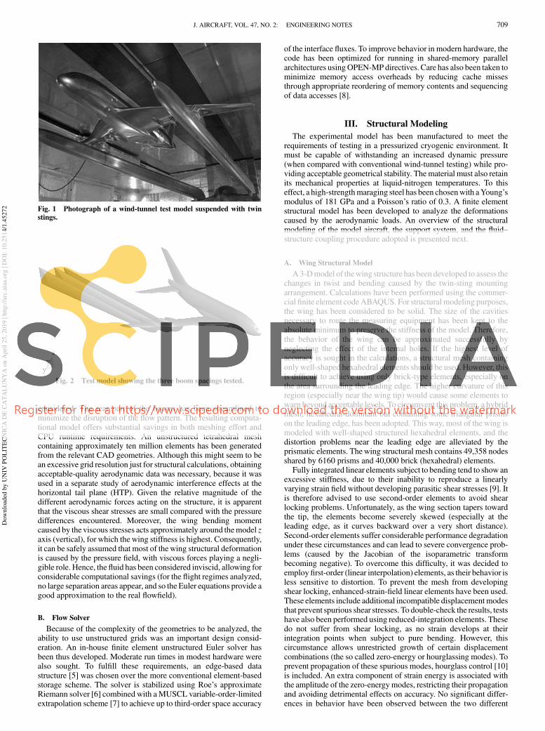
The analysis geometry involves a wing–body–tail test-modelconfiguration supported by twin stings. The shape corresponds to amodern large jetliner. The 1:50-scale model has a half-span of 79 cm.In the present work, three different support configurations have beenanalyzed to evaluate their effect on model deformation. These shallbe referred to as outboard, intermediate, and inboard boompositions.The respective sting spacings are 43, 35, and 30 in., corresponding to69, 56, and 48%spanwise positions (this choice of values allowed thereuse of an existing yoke plate, thus saving costs). All of them havebeen tested during the conventional (i.e., noncryogenic) wind-tunneltest campaign. Some cryogenic-wind-tunnel entries were alsoscheduled using the intermediate spacing. The outermost boomposition was chosen based purely on the allowable material stressesand is meant to provide an upper limit on the aeroelastic deforma-tions. The intermediate position is representative of standard experi-mental practice, and the smallest boom spacing was selected to gainunderstanding on the interference effects over the empennage causedby the twin-sting arrangement. Because of the fact that flow condi-tions and geometry are symmetric with respect to the aircraftmidplane (x–z), a half-symmetric computational model is used.Figure 2 shows the test-model geometry and the different stingpositions studied here.
As Fig. 2 shows, the full assembly of the wind-tunnel supportsystem has not been modeled (the yoke plate and boss have beenremoved). To simplify the geometry, only the stings have been
Received 4 May 2009; revision received 14 December 2009; accepted forpublication 22 December 2009. Copyright © 2010 by the American Instituteof Aeronautics andAstronautics, Inc. All rights reserved. Copies of this papermay be made for personal or internal use, on condition that the copier pay the$10.00 per-copy fee to the Copyright Clearance Center, Inc., 222 RosewoodDrive, Danvers, MA 01923; include the code 0021-8669/10 and $10.00 incorrespondence with the CCC.
∗Postdoctoral Researcher, Aerospace Department, Edificio C1, CampusNorte, Gran Capitán.
†Research Staff, Aerospace Department, Edificio C1, Campus Norte, GranCapitán.
‡Director, Edificio C1, Campus Norte, Gran Capitán.
JOURNAL OFAIRCRAFT
Vol. 47, No. 2, March–April 2010
708
Dow
nlo
aded
by U
NIV
PO
LIT
EC
NIC
A D
E C
AT
AL
UN
YA
on A
pri
l 25, 2019 |
htt
p:/
/arc
.aia
a.org
| D
OI:
10.2
514/1
.45272
considered. The rear part of the booms has been streamlined tominimize the disruption of the flow pattern. The resulting computa-tional model offers substantial savings in both meshing effort andCPU runtime requirements. An unstructured tetrahedral meshcontaining approximately ten million elements has been generatedfrom the relevant CAD geometries. Although this might seem to bean excessive grid resolution just for structural calculations, obtainingacceptable-quality aerodynamic data was necessary, because it wasused in a separate study of aerodynamic interference effects at thehorizontal tail plane (HTP). Given the relative magnitude of thedifferent aerodynamic forces acting on the structure, it is apparentthat the viscous shear stresses are small compared with the pressuredifferences encountered. Moreover, the wing bending momentcaused by the viscous stresses acts approximately around themodel zaxis (vertical), for which the wing stiffness is highest. Consequently,it can be safely assumed that most of thewing structural deformationis caused by the pressure field, with viscous forces playing a negli-gible role. Hence, the fluid has been considered inviscid, allowing forconsiderable computational savings (for the flight regimes analyzed,no large separation areas appear, and so the Euler equations provide agood approximation to the real flowfield).
B. Flow Solver
Because of the complexity of the geometries to be analyzed, theability to use unstructured grids was an important design consid-eration. An in-house finite element unstructured Euler solver hasbeen thus developed. Moderate run times in modest hardware werealso sought. To fulfill these requirements, an edge-based datastructure [5] was chosen over the more conventional element-basedstorage scheme. The solver is stabilized using Roe’s approximateRiemann solver [6] combined with aMUSCL variable-order-limitedextrapolation scheme [7] to achieve up to third-order space accuracy
of the interface fluxes. To improve behavior in modern hardware, thecode has been optimized for running in shared-memory parallelarchitectures usingOPEN-MP directives. Care has also been taken tominimize memory access overheads by reducing cache missesthrough appropriate reordering of memory contents and sequencingof data accesses [8].
III. Structural Modeling
The experimental model has been manufactured to meet therequirements of testing in a pressurized cryogenic environment. Itmust be capable of withstanding an increased dynamic pressure(when compared with conventional wind-tunnel testing) while pro-viding acceptable geometrical stability. Thematerial must also retainits mechanical properties at liquid-nitrogen temperatures. To thiseffect, a high-strengthmaraging steel has been chosenwith aYoung’smodulus of 181 GPa and a Poisson’s ratio of 0.3. A finite elementstructural model has been developed to analyze the deformationscaused by the aerodynamic loads. An overview of the structuralmodeling of the model aircraft, the support system, and the fluid–structure coupling procedure adopted is presented next.
A. Wing Structural Model
A3-Dmodel of thewing structure has been developed to assess thechanges in twist and bending caused by the twin-sting mountingarrangement. Calculations have been performed using the commer-cial finite element codeABAQUS. For structural modeling purposes,the wing has been considered to be solid. The size of the cavitiesnecessary to route the measuring equipment has been kept to theabsolute minimum to preserve the stiffness of the model. Therefore,the behavior of the wing can be approximated successfully byneglecting the effect of the internal holes. If the highest level ofaccuracy is sought in the calculations, a structural mesh containingonlywell-shaped hexahedral elements should be used. However, thisis difficult to achieve using only brick-type elements, especially onthe area surrounding the leading edge. The higher curvature of thisregion (especially near the wing tip) would cause some elements towarp beyond acceptable levels. To circumvent this problem, a hybridmesh, hexahedral-dominant but containing some triangular prismson the leading edge, has been adopted. This way, most of the wing ismodeled with well-shaped structured hexahedral elements, and thedistortion problems near the leading edge are alleviated by theprismatic elements. Thewing structural mesh contains 49,358 nodesshared by 6160 prisms and 40,000 brick (hexahedral) elements.
Fully integrated linear elements subject to bending tend to show anexcessive stiffness, due to their inability to reproduce a linearlyvarying strain field without developing parasitic shear stresses [9]. Itis therefore advised to use second-order elements to avoid shearlocking problems. Unfortunately, as the wing section tapers towardthe tip, the elements become severely skewed (especially at theleading edge, as it curves backward over a very short distance).Second-order elements suffer considerable performance degradationunder these circumstances and can lead to severe convergence prob-lems (caused by the Jacobian of the isoparametric transformbecoming negative). To overcome this difficulty, it was decided toemploy first-order (linear interpolation) elements, as their behavior isless sensitive to distortion. To prevent the mesh from developingshear locking, enhanced-strain-field linear elements have been used.These elements include additional incompatible displacementmodesthat prevent spurious shear stresses. To double-check the results, testshave also been performed using reduced-integration elements. Thesedo not suffer from shear locking, as no strain develops at theirintegration points when subject to pure bending. However, thiscircumstance allows unrestricted growth of certain displacementcombinations (the so called zero-energy or hourglassing modes). Toprevent propagation of these spurious modes, hourglass control [10]is included. An extra component of strain energy is associated withthe amplitude of the zero-energymodes, restricting their propagationand avoiding detrimental effects on accuracy. No significant differ-ences in behavior have been observed between the two different
Fig. 1 Photograph of a wind-tunnel test model suspended with twin
stings.
Fig. 2 Test model showing the three boom spacings tested.
J. AIRCRAFT, VOL. 47, NO. 2: ENGINEERING NOTES 709
Dow
nlo
aded
by U
NIV
PO
LIT
EC
NIC
A D
E C
AT
AL
UN
YA
on A
pri
l 25, 2019 |
htt
p:/
/arc
.aia
a.org
| D
OI:
10.2
514/1
.45272

element formulations, and so the results can be considered to bereliable.
B. Support Mechanism Modeling
Large vertical displacements along the model z axis and rotationsalong the y axis (spanwise direction) are to be expected, due to thebending deformation of the booms. The effects of displacements ofthe supporting mechanism on the measurements carried out duringtesting are quite limited, because model attitude is measured viainclinometers mounted on the fuselage. Therefore, the fuselageincidence is always set to the correct value, irrespective of the level ofdeformation experienced by the booms.Nevertheless, boom stiffnessmust be properly accounted for to obtain realistic wing-deformationpredictions. There is an important coupling caused by the torsionalstiffness of the booms, which restricts the rotation of thewing aroundthe x axis (fuselage direction) and therefore hampers bendingdeformation. To reduce the complexity of the model while stillretaining this coupling effect, the stings have been modeled usingbeam elements. The bending and torsional stiffness of the beams hasbeen calculated from the detailed CAD model of the booms.
Thewing–boom adaptors consist of twomassive steel parts boltedtogether with the wing clamped in between. Given their generalproportions, the adaptors have been modeled as rigid, as theirstiffness is much higher than that of the booms and the wing section.The realistic simulation of the adaptor–wing junctionwould require avery detailed modeling of the attachment mechanism to produce anaccurate rendering of the stress field around the load-transfer area(including, for example, information about the bolt-adjustmenttorque). To avoid unnecessary complexity, the model has been sim-plified in this area. The load from the adaptors has been transferred tothe wing by rendering a group of elements around the fastenersextremely rigid and constraining their movements to those of theadaptor. This way, the load transfer is spread out over severalelements producing a locally smooth deformation field.
C. Body–Tail Section Modeling
The fuselage diameter is very large compared with the wingthickness, therefore its deformations are very small compared withthose of thewing.Moreover, the deformations sought are those of thewing so the computational complexity has been reduced byremoving the body–tail assembly from the structural mesh. To thiseffect, the overall pressure load acting on the body–tail assembly hasbeen reduced to a point force and moment about the wing meanaerodynamic center. Hence, the effects of the body–tail group areaccounted for without increasing the number of degrees of freedomin the model.
D. Modeling of the Body–Wing Interface
The load-transfer mechanism at the wing root depends on thegeometrical details of the junction (e.g., on the type and distributionof fasteners). A detailed model of the interface was not considerednecessary as the stiffness of the wing is maximum in this area (due tothe large chord and thickness). Therefore, most of the expecteddisplacements arise from the deformation of sections farther awayfrom the fuselage. Moreover, the wing–fuselage junction is coveredby the belly fairing (which is a separate component of the testmodel),so the local behavior of the underlying structure has a very limitedimpact on the external shape. In the simplified approach adopted agroup of elements on the upper and lower sides of the wing root (sixalong each) has been lumped into a single rigid body. The masterreference node (the node to which the displacements of all the nodesin the rigid body are tied to) is the reduction point of the fuselage–tailaerodynamic loads (i.e., themean aerodynamic center). Thisway, therotations of the wing root section and the fuselage are constrained toremain equal, whereas a certain level of warping is allowed for thewing (fully constraining the warping of the section could give rise toan unrealistic torsional stiffness at the wing root). Note that this formof attachment can be considered similar to spot-welding the wingroot to the fuselage body. Furthermore, x–z symmetry conditions for
the model are enforced constraining the motion of the body–tailreference node along the y axis aswell as the rotations about the x andz axes. Thus, the effects of the body–tail assemble on the wing arereproduced in a very computationally effective way.
E. Transfer of the Aerodynamic Loads to the Structural Model
As the fluid and solid grids are not congruent, an automatedmethod to map the pressure distribution from an arbitrary CFD gridinto the structural mesh has been developed. This load transferprocedure is carried out in four main steps:
1) The CFD surface mesh is split in two groups, the first onecontaining elements belonging to the body–tail area and the secondone including all the remaining surface facets.
2) The pressures acting on the body and tail are reduced to a globalforce and moment acting on the reference point.
3) For each surface facet of the structural grid, the centroid iscalculated and the element of the CFD mesh it lays on is sought.
4) The average pressures at the centroids of the structural meshfacets are interpolated using values from the elements of the CFDgrid on which they are located. These pressures are subsequentlyconverted to nodal generalized forces of the solid model.
The third step of the process could be extremely lengthy if a brute-force approach were used to find the correspondence between thefluid and the structural grids. For a CFD grid containing nc facets anda structural mesh having ns surface elements, a total of nc � ns
checkswould have to be performed. It is clear that this is an extremelyinefficient process that calls for improvement. To achieve this, abinning algorithm has been implemented [8]. A background, uni-formly spaced, hexahedral structured mesh is created that encom-passes the complete wing. In the first step, the CFD facets areassigned to the elements of the backgroundmesh (the bins) accordingto the position of their centroids. Given the uniform spacing of thebins, the parent bin of any point can be located by simply operatingon its coordinates, and the process is thus extremely fast. In thesecond step, the underlying fluid element of each structural face isfound by searching only across the elements belonging to the samebin. The cost of the search is then reduced by a factor equal to thenumber of elements on the background mesh. As the number of binscan be made as large as needed, the speedup attained is quiteremarkable.
F. Coupling Procedure
The pressure distribution obtained from the CFD solution isconverted to nodal generalized forces applied on the structure, but thedisplacements and rotations thus obtained are not used to deform theaerodynamic model and recalculate the pressure forces. No iterationbetween the CFD and the structural model is performed and,consequently, the static aeroelastic equilibrium of the wing is notachieved. As the structure of the test model is very stiff (making thedisplacements small), neglecting the effect of the deformations on theflowfield does not lead to severe errors (from the structural point ofview). To validate this assumption, a cross-check has been madeagainst experimental deformation data gathered during cryogenic-wind-tunnel testing. A limited set of direct displacement measure-ments using the image pattern correlation technique (IPCT) andstereo pattern tracking (SPT) were available for comparison. Bothtechniques are based on photogrammetric principles [11,12]. In SPTa regular array of spot markers is tracked, whereas IPCT relies onrandomly sprayed paint droplets. By comparing images of themarkers taken from different points of view, their 3-D coordinatescan be inferred, thus allowing determination of the displacements.The experimental measurements cover only the intermediate boomspacing and therefore do not provide a great insight on the effect ofsting position. They are, however, useful as a means to validate thenumerical approach.
Using the methodology outlined in the previous sections, aprediction of the wing twist deformation encountered during cryo-genic testing was made. The good agreement between the numericaland experimental results is shown in Fig. 3. The general trend (aswellas the actual rotation values) is well-captured. It must be stressed that
710 J. AIRCRAFT, VOL. 47, NO. 2: ENGINEERING NOTES
Dow
nlo
aded
by U
NIV
PO
LIT
EC
NIC
A D
E C
AT
AL
UN
YA
on A
pri
l 25, 2019 |
htt
p:/
/arc
.aia
a.org
| D
OI:
10.2
514/1
.45272

the differences seen on the graph are of limited relevance. Duringtesting, discrepancies on the order of 10%were sometimes observedbetween the SPT and IPCT measurements. Thus, the differences inFig. 3 may be due to experimental uncertainties. The one-waycoupling procedure adopted in this work then seems very accurate.
IV. Wing Deformation Analysis
In this section, the influence of the angle of attack on wingdeformation is analyzed for the different sting spacings. All theresults presented here correspond to a fixed Mach number of 0.85,representative of cruise conditions. Keeping the Mach numberconstant removes some purely aerodynamic effects from the analysis(for example, the corresponding changes in the dynamic pressureinside the test chamber) and simplifies the interpretation of theresults. To transform the Cp values obtained from the CFD solutioninto pressure loading, a constant stagnation pressure of 1 bar isassumed to match the test-chamber conditions encountered duringthe conventional wind-tunnel runs.
To assess the effects of themounting system onwing deformation,two parameters have been investigated. The first one is the rotationangle about the y axis of the wing sections (also termed twist angle).This parameter is considered to be the most relevant result from thestructural analysis, because it represents the local change in angle ofattack due to aeroelastic effects and has a major impact on thedownwash distribution at the tail. For each of the cases under study,the twist angle has been computed at several spanwise stations in thefollowing manner:
twist angle � tan�1
�
uLE
Z � uTE
Z
xLE � xTE
�
(1)
where uLE
Z and uTE
Z , respectively, denote the vertical displacement ofpoints located at the leading xLE and the trailing edge xTE of eachwing section for which the twist angle is computed. Moreover, thefuselage rotation has been subtracted from the results given byEq. (1), forcing the computed twist to be zero at thewing root section.It is worth remembering that the inclinometer used for controllingmodel angle of attack is located inside the fuselage. Therefore, thewing root incidence is a suitable reference value to compute twist. Inother words, the angle of attack at the root is always set to the propervalue, irrespective of the testing conditions, and so the fuselagerotation can be taken as zero. The second parameter under study is thevertical displacement of the wing (along the z axis). This value isprovided mainly for reference purposes (it helps in depicting thewing deformed shape), as it is not so important from the point of viewof aerodynamic interference (its effect in downwash is quite limited).The quarter-chord line is adopted as a reference for plotting thevertical displacements given its special importance in aerodynamics.The most relevant information obtained from the multiple analysisruns is presented in the next section. The displacements and rotationsplotted haven been normalized using the maximum value obtainedthroughout the simulation campaign. Therefore, their absolute valuesare always contained inside the [0, 1] interval. As a reference, themaximum wing deflection was close to 10 mm and the maximumrotation was approximately 1�.
It should be noted that the deformations presented in this work areonly due to aerodynamic forces, as the contribution of the modelweight has not been accounted for. To evaluate the mechanical effectof the twin sting on wing deformation, a limited number of structuralruns without booms (booms-off) have been performed. For thesecomputations, the model displacement has been constrained byclamping the body–tail reference node (thus achieving an effectsimilar to a conventional fuselage-attached sting).
A. Effect of Sting Position on Wing Deformation
The wing vertical displacement and rotation computed for afreestreamMach numberM
1� 0:85 are presented in Figs. 4 and 5.
Note that the displacement pattern inboard of the wing–boomadaptors is reversed with respect to the situation when the model issupported at the fuselage. A downward reaction at the booms isneeded to counteract the lift force acting on the test model; therefore,the root section rises relative to the boom area. Outboard from thestings, the usual behavior is recovered; i.e., the upward verticaldeflection increases toward the wing tip.
Figure 5 shows that the twist angle steadily decreases from the rootto the wing tip for the booms-off condition. This is to be expected,due to the positive sweep of the wing. The twin sting alters thisbehavior causing the twist angle to increase near thewing root. As theangle of attack increases, this trend becomes more pronounced. Theabsolute value of twist at the wing tip observed for the booms-onconfiguration is smaller than the value attained when the model issupported through the fuselage. This behavior can be explained asfollows. When the angle of attack increases, the upward lift force
Fig. 3 Simulated vs experimental wing twist; M1� 0:85. �� 2�,
midboom position, and HTP incidence setting��2�.
Fig. 4 Effect of support mechanism on wing deflection;M1� 0:85, �� 0�, and 2.5�.
J. AIRCRAFT, VOL. 47, NO. 2: ENGINEERING NOTES 711
Dow
nlo
aded
by U
NIV
PO
LIT
EC
NIC
A D
E C
AT
AL
UN
YA
on A
pri
l 25, 2019 |
htt
p:/
/arc
.aia
a.org
| D
OI:
10.2
514/1
.45272

originated at the HTP grows, causing an additional nose-down(negative) moment on the fuselage. This pitch unbalance must becompensated by the sting booms, which react with an oppositetorsion moment, producing a nose-up (positive) rotation of the wingsections inboard of the adaptors. On the other hand, due to thebackward sweep of the wing, there is a coupling between bendingdeformation and rotations (with local angle of attack decreasingwhen the wing bends upward). Close to the wing root, the positiverotation due to the adaptor moment dominates, causing the twistangle to increase initially. In the area between the stings, the verticaldisplacement pattern is reversed, and so bending deformations do notlower the local angle of attack.Moving further outboard, the effect ofboom torsionvanishes (the outer section of thewing is only subject tothe aerodynamic loads with the adaptors having no effect) and theusual booms-off trend is recovered.Despite the important differencesin the twist pattern, the overall wing rotation is reduced when usingtwin booms (except for the widest spacing at zero angle of attack, asituation in which deformations are small across the board anyway).The same can be said about the bending deflections, but in this case,the change is more dramatic, as the displacement field is completelyreversed. It is important to keep in mind, however, that the verticaldisplacements are much less likely to have a negative impact on tail-force measurements than the changes in local angle of attack.
Regarding the effect of sting position, numerical calculationspredict larger deflections when the supports are placed farther awayfrom the symmetry plane. This was to be expected; on the other hand,the similarity of the behavior of the two smaller spacings isremarkable. In particular, regarding the twist distribution (Fig. 5),there is almost no difference between both configurations (thedifferences observed in the plot are probably within the margin of
error of the numerical model). This is due to the relative proximity ofthe two innermost adaptor positions and the large stiffness of thewing section near the root (where both chord and thickness arehighest).Moving to the outermost sting position, amarked change ofthe curves is seen, with the reversed deformation pattern inboard ofthe boom becoming more pronounced. In this case, the wing isattached at a section of lower stiffness, farther apart from thesymmetry plane and, consequently, the effects of torsion becomeapparent.
B. Effect of the Angle of Attack
An increment of the angle of attack gives rise to a higher wingloading that, in turn, increases the vertical spanwise displacements.The local rotation angle is also affected in a similar way, though to alesser degree. As explained before, this is due to the change in HTPlift (the testmodel is not trimmed), which causes a positivewing twistinboard of the adaptors. The behavior is more pronounced for theouter wing–boom adaptor position, as the part of the wing subject tothis torsional loading spans a longer distance. Figure 6 shows thecomputed effects of the angle of attack for the outer sting position.
Observe that close to the wing root, the twist plots change verylightly, with the angle of attack reflecting the elevated stiffness of thewing. It is possible to observe at the spanwise station �� 0:55 thatthe rotation angle is insensitive to changes in themodel incidence andremains almost constant. This reflects the change in supportconditions between the different areas of the wing. Close to thefuselage, the effect of the booms is important; near the tip, thebehavior is similar to the booms-off condition; and in between, thereis a point at which a balance is achieved.
Fig. 5 Effect of support mechanism on wing twist;M1� 0:85, �� 0�, and 2.5�.
Fig. 6 Effects of the angle of attack on wing deformation, outermost boom position, andM1� 0:85.
712 J. AIRCRAFT, VOL. 47, NO. 2: ENGINEERING NOTES
Dow
nlo
aded
by U
NIV
PO
LIT
EC
NIC
A D
E C
AT
AL
UN
YA
on A
pri
l 25, 2019 |
htt
p:/
/arc
.aia
a.org
| D
OI:
10.2
514/1
.45272

C. Global Effects of the Twin-Sting Support on Wing Deformation
With the aim of giving a better understanding of the effects of thetwin sting on the wing, its deformed shape is drawn for both thebooms-on and booms-off configurations (Fig. 7). The differences onthe isodisplacement lines computed for both cases are quite apparent.
For the booms-off configuration, the displacement isolines areapproximately perpendicular to themidchord line (more precisely, tothe elastic axis of the wing). However, when the sting is attached tothe wing, the displacement pattern is vastly different.
Notice that near the wing root, the lines are perpendicular to thefuselage, which indicates that the displacement field correspondsapproximately to a rigid-body rotation of the fuselage. Part of thismotion is due to bending of the booms (which causes a rigid-bodydisplacement of the completemodel, wings included). There is also acontribution arising from wing torsional deformation between thefuselage and the sting. This can be evidenced by comparing thedistance between the isodisplacement contours at the root and boomsections. The spacing between the curves being wider at the stingposition means that the wing root section is pitching upward withrespect to the boomarea. Remember once again that the pitch sensingdevice that controls the test-model attitude is located inside thefuselage, and so the rigid-body displacements of the complete modeldo not have any affect on the measurements. Therefore, only thetorsional deformation has to be accounted for as a true aeroelasticeffect.
Halfway between the fuselage and the boom, the lines curvetoward the leading edge, creating a motive that is somewhat reminis-cent of the free-wing configuration. However, once the wing–boomadaptor area is reached, the deformation pattern changes abruptly.The boom stiffness restricts the rotation of the wing sections, and thevertical displacement field over the outboard wing region becomesalmost constant.
Another interesting result from the graphs is that whereas thedisplacement field is completely reversed with respect to the booms-off situation (i.e., the wing bends downward instead of upward), thesame is not true for the twist distribution (Figs. 4 and 5). Positive twistangles are only obtained for thewidest spacing, and even in that case,they are small compared with the negative rotations that occur on theoutboard part of the wing (Fig. 5). The cause is the large pitch-upmoment introduced by the HTP for moderate values of the fuselageincidence. When the model attitude is close to horizontal, there is anet downward force acting on theHTP (the testmodel is not trimmed)that causes the boom section to rotate downwardwith respect towingroot. This negative twist is partially countered by the positivecontribution due to bending (as the wing deflection distributioninboard of the adaptor is reversed, the effect of the wing sweep is toincrease the local angle of attack). The two competing effects (torsionand bending) partially cancel each other, resulting in a very flat twistplot inboard of the wing–boom adaptors (Fig. 6 illustrates thisbehavior). Once the angle of attack is increased, the tail downwardforce is reduced, whereas the positive twist due to wing bendingincreases as a result of a higher wing load. The twist reversalphenomenon is thereforemost pronounced at high incidence settings:in fact, it disappears when the angle of attack is negative (see Fig. 6).
V. Conclusions
It has been shown that the one-way coupling procedure developedseems to be adequate for assessing the wing aeroelastic behavior inthe frame of these particular research activities. Direct measurementsin a cryogenic test environment corroborate the accuracy of theresults. It is important to stress that the dynamic pressure expectedduring cryogenic-tunnel entries is higher than (about three times aslarge as) the value encountered during conventional testing (which isthe subject of this study). If the results are accurate in a situation inwhich large deformations are produced due to high-pressure loading,it seems very reasonable to expect an even better agreement underless severe conditions.What is more, in the vast majority of cases, thenet effect of twist deformations is to reduce the local angle of attack;thus, the geometric changes on the real test model are not expected tobe larger than those predicted here (wing load is reduced, due to thedeformation). Hence, the deformations calculated can be consideredas a realistic bound of the real ones.
In the past, there has been an important level of uncertaintyassociated with twin-sting testing. It was speculated that the reduc-tion in aerodynamic interference at the tail could be offset by largechanges in downwash caused by increasedwing twist. This study hasproven these suspicions to be unfounded (within the range ofparameters covered). The global deformations due to the twin-stingmounting system are not higher than those expected when a con-ventional single-sting support system is employed (booms-offconfiguration). The fact that the deformation pattern tends to reverseinboard of the booms causes the average displacements to becomesmaller (the effects occurring inboard and outboard of the adaptorstend to cancel each other). This holds true even for the largest boomspacing, showing that there is much greater freedom in choosing theoptimum separation (for aerodynamic purposes) thanwas previouslythought possible.
On the negative side, it is apparent that the shape of the twistdistributions is vastly different from the booms-off case. This negatesthe possibility to reproduce the aeroelastic response of the freeaircraft over a wide range of flight conditions. This is further com-plicated because the deformation field depends not only on boomposition and model angle of attack, but also on HTP incidencesetting. Therefore, the shape of the model would have to be tailoredcarefully for specific test conditions if aeroelastic similarity is to beachieved. In particular, it is problematic to test the same model usingboth single- and twin-sting mounting. These negative findings arepartially offset by the fact that the actual values of the displacementsare smaller when using twin stings.
Acknowledgments
The authors would like to acknowledge the financial supportprovided by the REMFI (Rear-Fuselage and Empennage FlowInvestigation) project under the European Commissions’s SixthFramework Programme (contract number AST3-CT-2004-502895).Special thanks to Airbus and European Transonic Wind Tunnel forproviding the information used to validate the coupling scheme.
Fig. 7 Vertical displacement contours on the wing;M1� 0:85 and �� 2:5.
J. AIRCRAFT, VOL. 47, NO. 2: ENGINEERING NOTES 713
Dow
nlo
aded
by U
NIV
PO
LIT
EC
NIC
A D
E C
AT
AL
UN
YA
on A
pri
l 25, 2019 |
htt
p:/
/arc
.aia
a.org
| D
OI:
10.2
514/1
.45272

References
[1] Piat, J. F., and Steve, N., “Recent Experiments with New Twin-Debs-Sting Supports in Onera’s Large Wind Tunnels,” AIAA Paper 2002-2921, 2002.
[2] Lyonnet, M., Piat, J. F., and Roux, B., “Model Support InterferenceAssessment Using aMetric Rear Fuselage and a Twin-Sting at ONERAS2MA Windtunnel,” Proceedings of the ICEF 1994 Conference,ONERA, TP 1994-125 E, Turin, Italy, 1994.
[3] Quest, J., and Wright, M., “Investigation of a Modern TransonicTransport Aircraft Configuration over a Large Range of ReynoldsNumbers,” AIAA Paper 2002-0422, 2002.
[4] Gross, N., “ETW Analytical Approach to Assess the Wing Twistof Pressure Plotted Wind Tunnel Models,” AIAA Paper 2002-0310,2002.
[5] Luo, H., , Baum, J. D., and Löhner, R., “Edge-Based Finite ElementScheme for the Euler Equations,” AIAA Journal, Vol. 32, No. 6, 1994,pp. 1183–1190.doi:10.2514/3.12118
[6] Roe, P. L., “Approximate Riemann Solvers, Parameter Vectors andDifference Schemes,” Journal of Computational Physics, Vol. 43,
No. 2, Oct. 1981, pp. 357–372.doi:10.1016/0021-9991(81)90128-5
[7] Van Leer, B., “Towards the Ultimate Conservative Difference Scheme5: A Second Order Sequel to Godunov’s Method,” Journal of
Computational Physics, Vol. 32, No. 1,1979, pp. 101–136.doi:10.1016/0021-9991(79)90145-1
[8] Löhner, R., Applied CFD Techniques, Wiley, New York, 2001.[9] Zienkiewicz, O., and Taylor, R., The Finite Element Method, 5th ed.,
Vol. 1, Butterworth-Heinemann, Oxford, 2000.[10] Joldes, G. R., Wittek, A., and Miller, K., “An Efficient Hourglass
Control Implementation for the Uniform Strain Hexahedron Using theTotal Lagrangian Formulation,” Communications in Numerical
Methods in Engineering, Vol. 24, No. 11, 2007, pp. 1315–1323.doi:10.1002/cnm.1034
[11] Walter, U., ETW User Guide, ETW GmbH, Rept. ETW/D/95001/A,Cologne, Germany, Jan. 2004, http://www.etw.de/pdfs/ETW_USER_GUIDE.pdf [retrieved 4 Feb. 2010].
[12] Ruyten Sellers, M. E., “Demonstration of Optical Wing DeformationMeasurements at the Arnold Engineering Development Center,”AIAAPaper 2009-1520, 2009.
714 J. AIRCRAFT, VOL. 47, NO. 2: ENGINEERING NOTES
Dow
nlo
aded
by U
NIV
PO
LIT
EC
NIC
A D
E C
AT
AL
UN
YA
on A
pri
l 25, 2019 |
htt
p:/
/arc
.aia
a.org
| D
OI:
10.2
514/1
.45272