numerical modeling of sampling airborne radioactive particles ... - cn.comsol…€¦particle...
TRANSCRIPT
Numerical Modeling of Sampling Airborne RadioactiveParticles Methods from the Stacks of Nuclear Facilities in
Compliance with ISO 2889
Cambridge – September 18, 2014
Piergianni GeraldiniSogin Spa – Mechanical Design DepartmentVia Torino 6, 00184 Rome – Italy, [email protected]

2Presentation outline
• Introduction
• Sampling scheme
• ISO 2889 requirements
• Computational domain and mesh
• Governing equations
• Li&Ahmadi model for particle-surface interactions
• Computational Strategy
• Results
• Conclusions

3IntroductionNuclear facilities discharge the off-gas into the atmosphere and suitablemonitoring and recording systems are required to protect the environment,workers and surrounding public.
The amount of radioactive substances (activity concentration) released from the stack hasto be measured. A known sample amount (mass flow) is withdrawn from the stack andanalyzed by Continuous Air Monitoring system. The ISO 2889 sets the performancecriteria and recommendations required for obtaining valid measurements.
The numerical study is performed in order to:
• determine if a preliminary stack design meets therequirements of ISO 2889 under nominal and reducedexhaust flow conditions (fire scenario) and particleaerodynamic diameter modifications (HEPA filterdisruption);
• obtain indications about the geometrical andfluidynamical design for well mixed stream (one pointsampling);
• reduce the design and field costs for future projectusing the similarity laws.
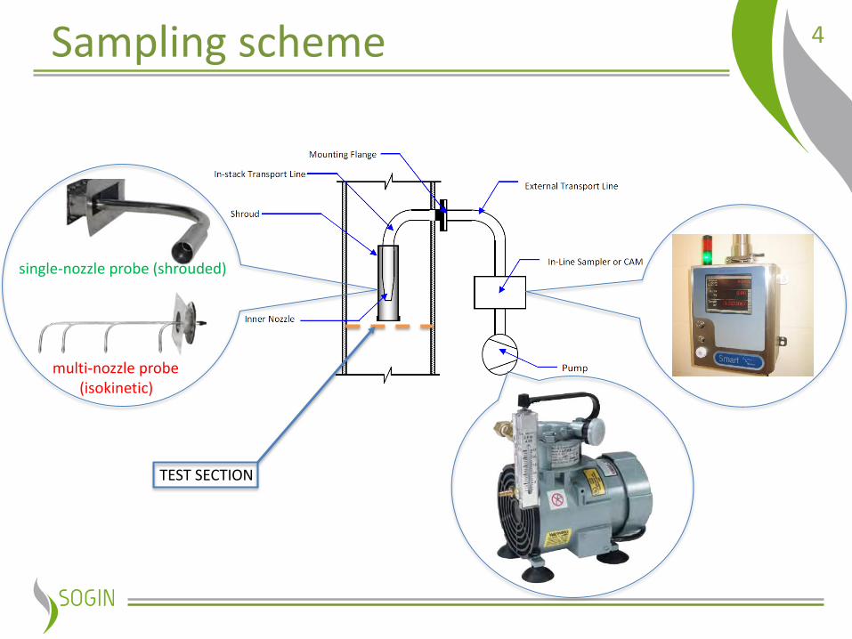
4Sampling scheme
TEST SECTION
multi-nozzle probe(isokinetic)
single-nozzle probe (shrouded)

5ISO 2889 requirements
When well mixed conditions areachieved the sampling probe maycontain a single nozzle, in othercases a multi-nozzle probe may beused or can be required to get arepresentative sample
(*) PARTICLE AERODYNAMIC DIAMETER RECCOMENDED: 10 micron
(*)
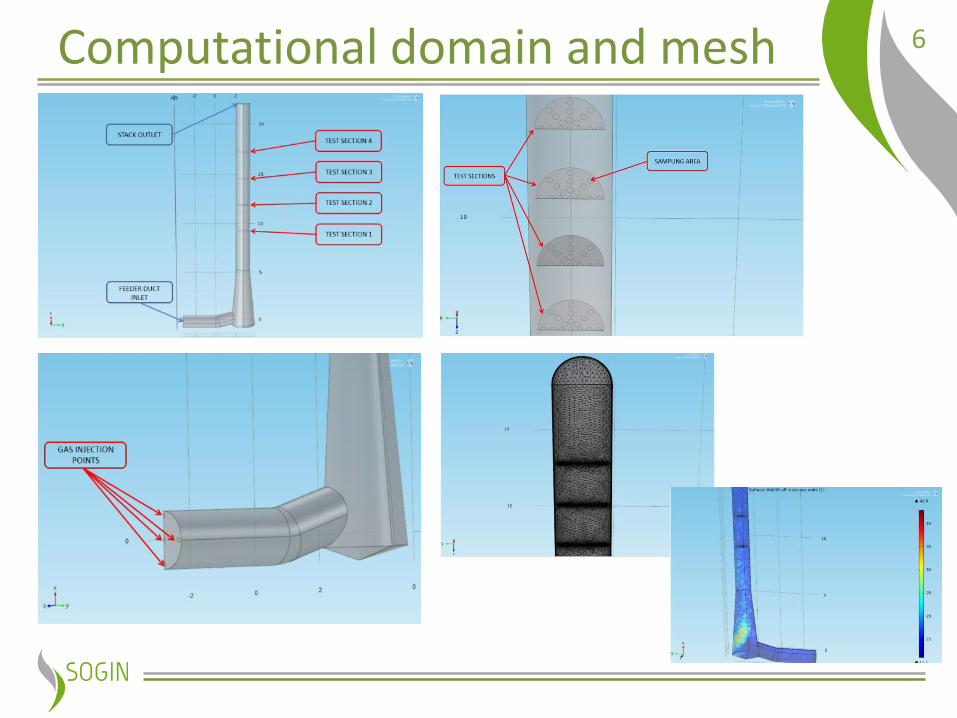
6Computational domain and mesh
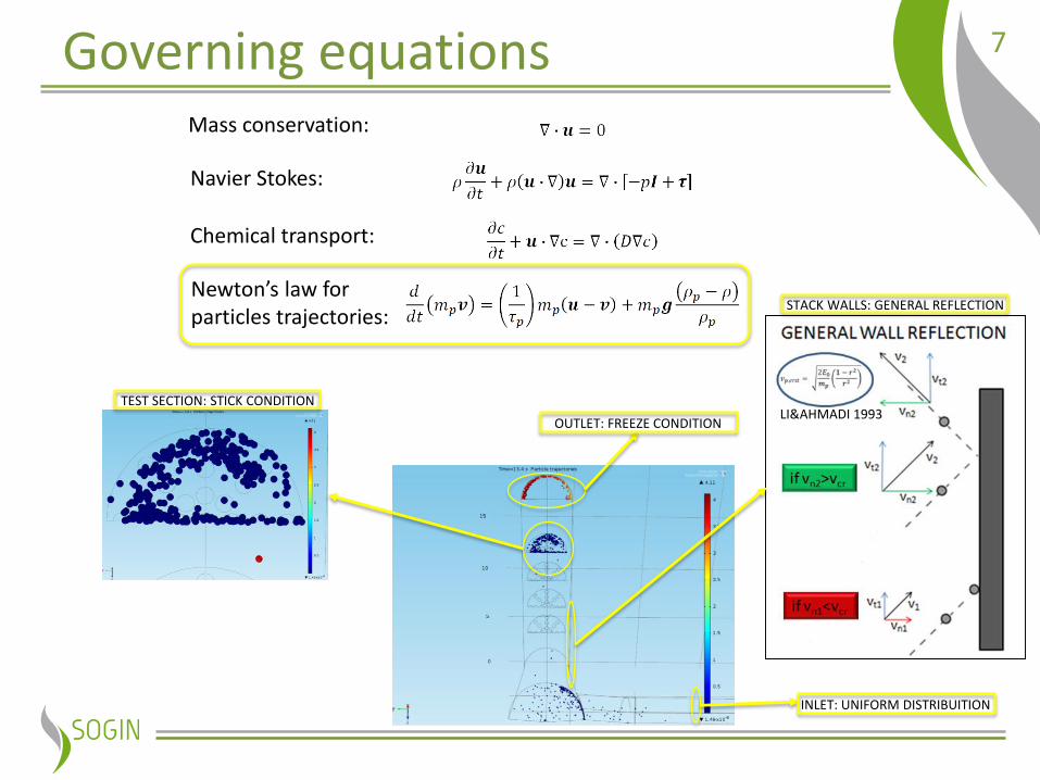
7Governing equationsMass conservation:
Navier Stokes:
Chemical transport:
Newton’s law for particles trajectories:
INLET: UNIFORM DISTRIBUITION
STACK WALLS: GENERAL REFLECTION
TEST SECTION: STICK CONDITION
OUTLET: FREEZE CONDITIONLI&AHMADI 1993
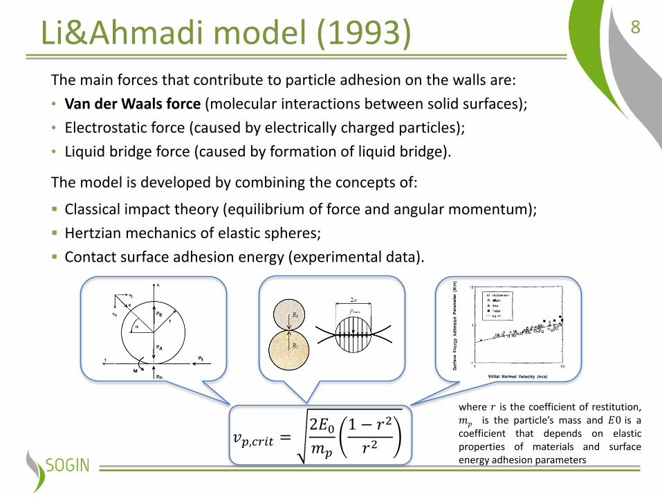
8Li&Ahmadi model (1993)The main forces that contribute to particle adhesion on the walls are:
• Van der Waals force (molecular interactions between solid surfaces);
• Electrostatic force (caused by electrically charged particles);
• Liquid bridge force (caused by formation of liquid bridge).
The model is developed by combining the concepts of:
Classical impact theory (equilibrium of force and angular momentum);
Hertzian mechanics of elastic spheres;
Contact surface adhesion energy (experimental data).
𝑣𝑝,𝑐𝑟𝑖𝑡 =2𝐸0𝑚𝑝
1 − 𝑟2
𝑟2
where 𝑟 is the coefficient of restitution,𝑚𝑝 is the particle’s mass and 𝐸0 is acoefficient that depends on elasticproperties of materials and surfaceenergy adhesion parameters
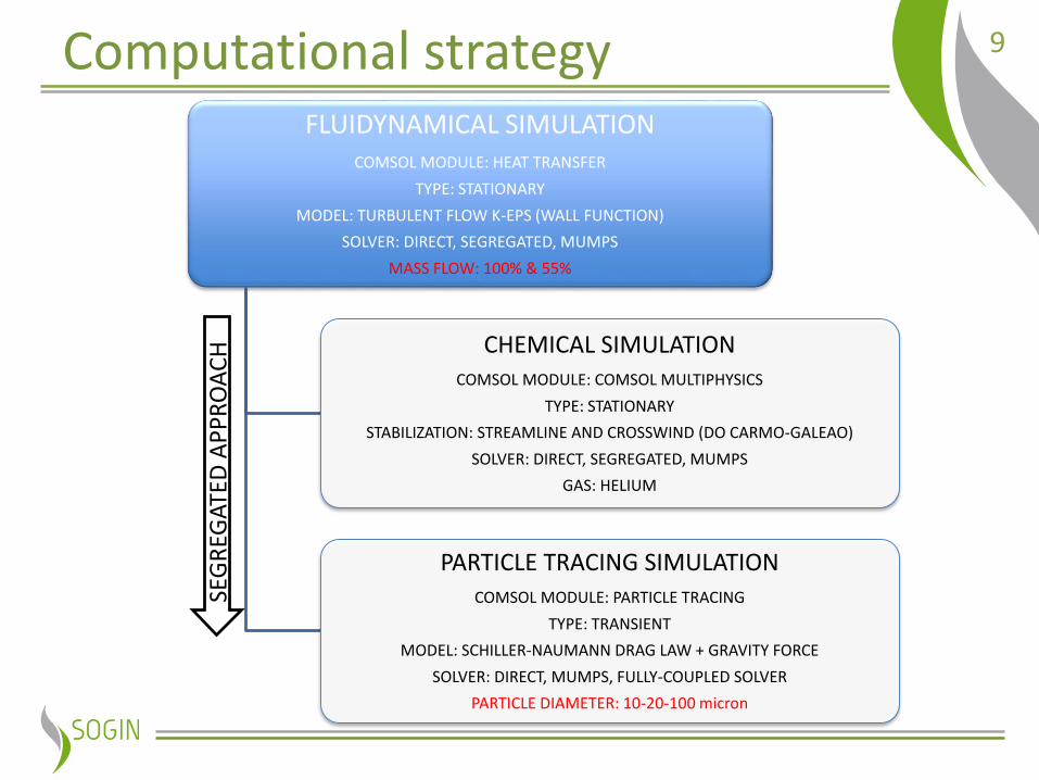
9Computational strategyFLUIDYNAMICAL SIMULATION
COMSOL MODULE: HEAT TRANSFER
TYPE: STATIONARY
MODEL: TURBULENT FLOW K-EPS (WALL FUNCTION)
SOLVER: DIRECT, SEGREGATED, MUMPS
MASS FLOW: 100% & 55%
CHEMICAL SIMULATIONCOMSOL MODULE: COMSOL MULTIPHYSICS
TYPE: STATIONARY
STABILIZATION: STREAMLINE AND CROSSWIND (DO CARMO-GALEAO)
SOLVER: DIRECT, SEGREGATED, MUMPS
GAS: HELIUM
PARTICLE TRACING SIMULATIONCOMSOL MODULE: PARTICLE TRACING
TYPE: TRANSIENT
MODEL: SCHILLER-NAUMANN DRAG LAW + GRAVITY FORCE
SOLVER: DIRECT, MUMPS, FULLY-COUPLED SOLVER
PARTICLE DIAMETER: 10-20-100 micron
SEG
REG
ATE
D A
PP
RO
AC
H

10Results (1/3): fluidynamical test
velocity field (100% flow):
Test results: the cyclonic flow angle is less than 20° for each
test section an mass flow studied; the velocity COV doesn’t exceed 20% for each
test section an mass flow studied.
11Results (2/3): chemical test
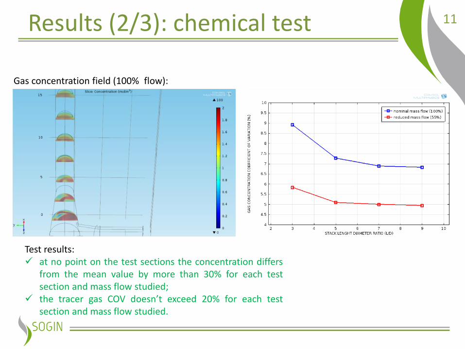
Gas concentration field (100% flow):
Test results: at no point on the test sections the concentration differs
from the mean value by more than 30% for each testsection and mass flow studied;
the tracer gas COV doesn’t exceed 20% for each testsection and mass flow studied.
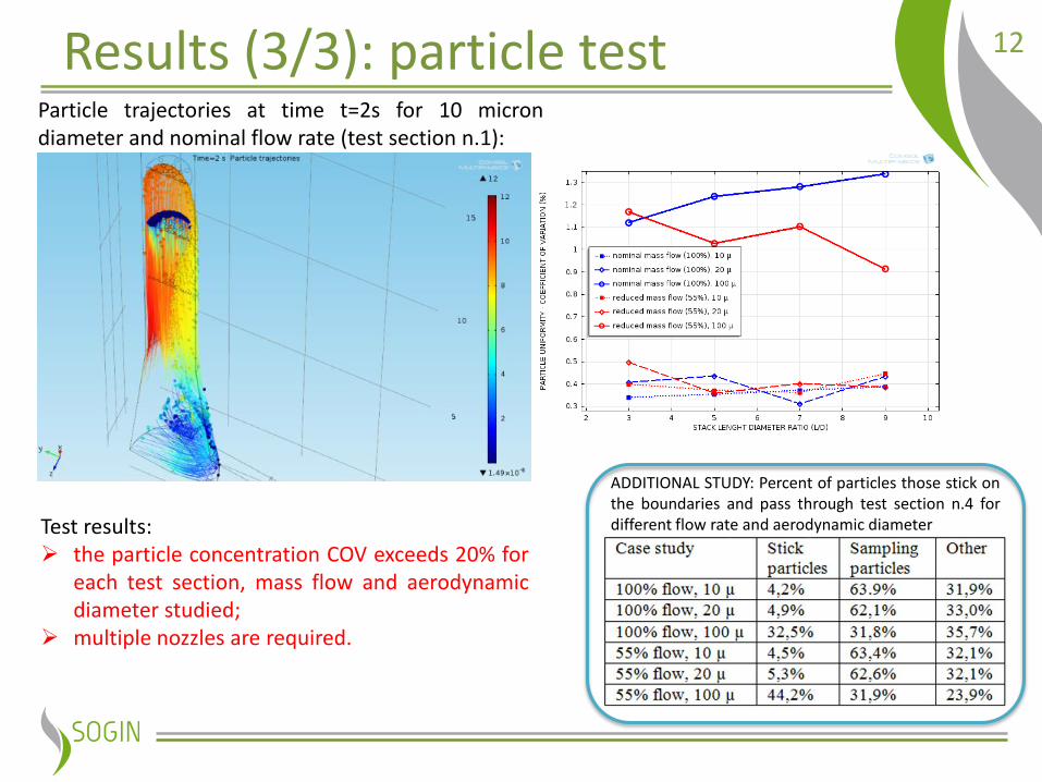
12Results (3/3): particle testParticle trajectories at time t=2s for 10 microndiameter and nominal flow rate (test section n.1):
ADDITIONAL STUDY: Percent of particles those stick onthe boundaries and pass through test section n.4 fordifferent flow rate and aerodynamic diameterTest results:
the particle concentration COV exceeds 20% foreach test section, mass flow and aerodynamicdiameter studied;
multiple nozzles are required.
13Conclusions
• all the ISO requirements are met except for aerosol well-mixeddistribution test;
• are obtained useful indications about the sampling systemperformance during off design conditions (mass flow andaerodynamic diameter modifications);
• the preliminary stack design required a multi nozzles probesampling system;
• future studies will be performed to evaluate the impact of feederduct angle variations and mixing elements introduction in order toachieve the well mixed conditions (one nozzle sampling probe).

14
Thank you for your attention!

15COV calculation spreadsheet
selection
Total number of particle in selection