numerical simulation of 4-digit inclined …...numerical 2d/3d modeling of naca 23012 airfoil and...
TRANSCRIPT

Uludag University Journal of The Faculty of Engineering, Vol. 22, No.1, 2017 RESEARCH DOI: 10.17482/uumfd.309470
169
NUMERICAL SIMULATION OF 4-DIGIT INCLINED NACA 00XX
AIRFOILS TO FIND OPTIMUM ANGLE OF ATTACK FOR
AIRPLANE WING
Haci SOGUKPINAR*
Received: 26.02.2016; revised: 05.12.2016; accepted: 28.02.2017
Abstract: In this paper, numerical analysis was conducted by using the SST turbulence model for
inclined NACA 0008, 0009, 0010, 0012, 0015, 0018, 0021, 0024 airfoils. Aerodynamic numerical
analysis of NACA 0012 airfoil was compared with the previously made experimental results in terms of
pressure and lift coefficient. The theoretical data were found to be fully compatible with experimental
results. Then, by simulating other airfoils using the same methods lift, drag, lift to drag ratio and the
pressure coefficient were calculated and compared with the angle of attack 0-14 degrees. According to the
calculations, lift coefficient of NACA 0008-0012 airfoil shows similar behaviors. With the increasing of
the airfoil thickness increment in the lift coefficient decreases for NACA 0015-0024 airfoils. Pressure
coefficients were also calculated for NACA profiles with angle of attack 10°. Pressure coefficients over
the airfoil decrease from leading edge toward the trailing edge but in the lower part it increases. With the
increasing of the airfoil thickness pressure coefficient decreases more slowly at the upper part but
increases more rapidly at the lower.
Key words: Airfoil, NACA 4 series, COMSOL, numeric analysis, airfoil simulation
Uçak Kanatlarında En İdeal Hücum Açısını Bulmak İçin 4 Rakamlı NACA 00xx Kanat
Profillerinin Nümerik Analizi
Öz: Bu çalışmada SST türbülans modeli kullanılarak 4 rakamlı NACA kanat profillerinden 0008, 0009,
0010, 0012, 0015, 0018, 0021, 0024 nümerik olarak analiz edilmiştir. NACA 0012 kanat profili deneysel
verilere sahip olduğu için önce bu kanat kesiti simüle edilip deneysel verilerle kaldırma kuvvet ve basınç
katsayısı bakımından kıyaslanmıştır. Bu çalışmada yapılan teorik hesaplamalar ile deneysel verilerin tam
olarak uyumlu olduğu gözlemlenmiştir. Daha sonra aynı yöntem kullanılarak diğer kanat profilleri simüle
edilerek kaldırma kuvveti, sürüklenme kuvveti ve profil yüzeyindeki basınç katsayıları ve kaldırma
kuvvet katsayısının sürüklenme kuvvet katsayısına oranı hesaplanarak farklı hücum açıları için
kıyaslamalar yapılmıştır. Yapılan hesaplamalara göre NACA 0008-0012 profilleri benzer aerodinamik
özellik göstermektedir. Kanat profillerinin kalınlığı arttıkça lift katsayısının azaldığı gözlemlenmiştir.
Ayrıca her profil için 10 derecelik hücum açısında basınç katsayıları hesaplanmış ve profil kalınlığı
arttıkça profilin üst kısmındaki basınç katsayısı daha yavaş azalırken alt kısımda daha hızlı bir şekilde
artmıştır.
Anahtar Kelimeler: Kanat profili, NACA 4 serisi, COMSOL, sayısal analiz, kanat simülasyonu
1. INTRODUCTION
NACA airfoil is designed generally for aircraft. Then, some designed airfoils have been also used in
wind turbines. First-designed 4 and 5 digit number NACA airfoils are expressed in terms of analytical
equations and can be obtained with the help of it. Later designed airfoil has more complex structure and
can obtain with the aid of theoretical calculations.
*Department of Energy Systems Engineering, Faculty of Technology, University of Adiyaman, Adiyaman 02040,
Turkey
Corresponding Author: H. Soğukpınar ([email protected])

Soğukpınar H.:Numerical Sim.of 4-Digit Inclined NACA 00xx Air.to Find Optimum Angle of Attack
170
Xu et al. (2015) conducted numerical simulations of NACA 4409, 4412, 4415 and 4418 series and lift and
drag coefficients for the NACA 4415 airfoil were calculated using k-w and SST turbulence models. With
this study they compared experimental data with theoretical one, the accuracy of the computational fluid
dynamics was observed. When the angle of attack passed 9 degree, increment in the lift coefficient was
very slow for NACA 4418 airfoil. NACA 4412 airfoil calculations showed that the lift coefficient
increased more quickly with respect to others. NACA 4412 airfoil showed the maximum lift coefficient
increment and second one was 4415 airfoil. Thumtha et al. (2009) and Aniket et al. (2015) conducted
numerical simulations of S809 airfoil. Studies were conducted in calculating the lift coefficient for
different angles of attack and obtained results were compared with the NREL experimental data. The
ideal angle of attack was determined by using the lift coefficients obtained for different angles. k-w
turbulence model was used for numerical analysis. Also Aniket et al. (2015) examined numerical
simulations of the modified NACA 0006 airfoil of Selig S1123, Eppler E423 and FX 74-CL5-140.
Studies confirmed the existence of high lift coefficient Selig S1123 airfoil. Zanotti et al. (2014) made
numerical 2D/3D modeling of NACA 23012 airfoil and results were compared with experimental data.
Studying with 3D modeling to examine the wing performance by the deep stall was found to be the most
appropriate modeling with respect to 2D. Guoqing et al. (2014) made numerical simulation of NACA
0015 airfoil with k-w shear stream transport turbulence model and numerical simulations were performed
to investigate the effects of synthetic jet control on separation and stall over rotor airfoils. Then,
parametric analyses were conducted for an OA213 rotor airfoil for same reason. Rostamzadeh et al.
(2014) made the numerical analysis of NACA 0021 airfoil. With the study, It was found that a skew-
induced mechanism accounted for the formation of streamwise vortices whose development accompanied
by flow separation in delta-shaped regions near the trailing edge. Mashud at al. (2014) made the
numerical simulations of NACA 0015 airfoil using k-w turbulence models and lift coefficient was
calculated and compared with experimental results.
In this study, numerical simulations was performed using the SST turbulence model for NACA
0008, 0009, 0010, 0012, 0015, 0018, 0021, 0024 airfoil. While only one or two airfoils were examined in
other studies but here 8 airfoils are investigated and compared with experiment. NACA 0012 airfoil
simulation results were compared with Ladson (1988) experimental lift coefficient data and Gregory and
O'Reilly (1970) experimental pressure coefficient data. Numerical simulation results show full
compliance with the experimental data. Other simulations were carried out using the same method with
NACA 0012. Then the coefficient of lift, drag and pressure were compared for NACA 0008, 0009, 0010,
0012, 0015, 0018, 0021, 0024 airfoils and the effect of the thickness of airfoil on the lift, drag and
pressure coefficients were investigated. According to numerical calculations with the increasing of the
airfoil thickness, increment in lift coefficient decreases. Pressure coefficient at the top of the airfoil
decreases from leading to the trailing edge but at the lower side it increases and pressure coefficient
decreases slowly at the upper side and increases more rapidly at the lower one.
2. COMPUTATIONAL METHOD
NACA airfoil shapes are expressed by numerical figures. In these series, NACA 4 series are the first
design airfoils. Putting the numbers in the numeric code on the equation, geometrical characteristics of
the airfoil is determined. The first digit in the 4-digit NACA series determines the maximum amount of
curvature and takes place in steps as the percentage amount of the chord length. The second digit
represents location of the maximum amount of curvature of the airfoil from the leading edge as a
percentage. The last two digits specify the maximum thickness of the airfoil as a percentage of chord
length. For NACA 2415 airfoil, the maximum curvature is 2% of the chord, starting from 40% from the
leading edge and maximum thickness of airfoil is 15% of chord length. If the first two digits of the
NACA are 00, it has a symmetrical structure and does not have a curvilinear geometry. For NACA 0012 airfoil, the maximum thickness is equal to 12% chord length with symmetrical
geometry. In symmetrical NACA airfoil geometry is expressed by equation (1) (Eastman, 2015).
[ √
( ) (
) ( ) (
)
(
)
( ) (
)
] (1)
Here, c is chord length, x is coordinate value between 0-c, is half thickness of airfoil for a given x
value, t is the percentage of the maximum thickness.

Uludag University Journal of The Faculty of Engineering, Vol. 22, No.1, 2017
171
Before US National Advisory Committee for Aeronautics (NACA), airfoil design had been done
randomly. Past experience would have been taken into account in the design. Since the early 1930s,
airfoil design had been made by NACA. Different airfoils were designed by NACA (new name is NASA)
and were performed wind tunnel tests at different concentrations. High Reynolds numbers were used in
the experimental tests. The main reason of the experimental test was to obtain the optimum airfoil shape
for the required application. The first experimental tests were conducted by NACA, limited to the 68
airfoil in the series. However, during test, some other supporting airfoils were also used. Design and wind
tunnel test results were plotted in the form of reports and it has been published. General shape of the
airfoil is given in Fig. 1.
Figure 1:
Cross-section of airfoil. In this study, SST turbulence model was used together with a Parametric Sweep for the angle of
attack to compute the different flows on a Mapped Mesh. To combine superior behavior of k-w model
close to the Wall region with the superior strength of the model, SST (Shear Stress Transport) model was
developed by Menter (1994). SST model is expressed in terms of k and with equation (2) and (3)
(COMSOL, 2015).
(( ) ) (2)
(( ) ) ( )
(3)
Where, P is the static pressure and can be represented with the equation (4).
( ) (4)
Here, production term and it is expressed with equation (5).
( ( ( ) )
( ) )
(5)
Turbulence viscosity is expressed with equation (6).
( ) (6)
Where, S is the characteristic magnitude of the mean velocity gradients and is expressed with the help of
equation (7)
√ (7)
The interpolation functions and are represented with the equation (8) and (9)
( * (√
)
(
)
+
) (8)
( (√
)
) (9)
Where, is the distance to the closest wall. For SST, default model constants are given by (COMSOL,
2015),
The computational conditions are as shown in Table 1.
Table 1. Computational condition

Soğukpınar H.:Numerical Sim.of 4-Digit Inclined NACA 00xx Air.to Find Optimum Angle of Attack
172
Density 1.2043 kg/m3
Wind speed 50 m/s
Angle of attack (Deg) 0.2,4,6,8,10,12,14
Turbulent kinetic energy 4.1840E-7 m2/s
2
Specific dissipation rate 2.7778 1/s
Chord lengths 1.8 m
Temperature 193 K
Reference pressure 1 atm
Reference Length 0.2 m
Reynolds number 6.00E+06
In this study, wind speed 50 m/s was set (Mack number 0.15) and adopted as incompressible flow.
Flow over the boundary conditions of airfoil was assumed to be turbulence because Reynolds number was
in the range of million. Air flowing over the airfoil surface was arranged to be inclined. Calculated
distance was taken 100 times of the chord length from the leading edge of airfoil to the inlet and taken
200 times from trailing edge to open boundary. Here, it was the purpose to minimize the impact of the
boundary region in calculation. A computational domain is given in Figure 2. Closed-up of airfoil section
is given in Figure 3 to be used for numerical calculations. No slip condition is applied on the surface of
the airfoil.
Figure 2:
Computational domain and boundary condition
Figure 3:
Closed-up of airfoil section
Uludag University Journal of The Faculty of Engineering, Vol. 22, No.1, 2017
173
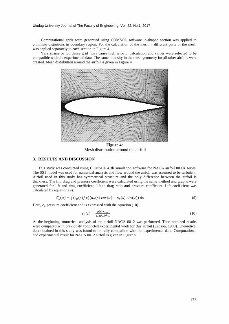
Computational grids were generated using COMSOL software. c-shaped section was applied to
eliminate distortions in boundary region. For the calculation of the mesh, 4 different parts of the mesh
was applied separately to each section in Figure 4.
Very sparse or too dense grid may cause high error in calculation and values were selected to be
compatible with the experimental data. The same intensity in the mesh geometry for all other airfoils were
created. Mesh distribution around the airfoil is given in Figure 4.
Figure 4:
Mesh distrubution around the airfoil
3. RESULTS AND DISCUSSION
This study was conducted using COMSOL 4.3b simulation software for NACA airfoil 00XX series.
The SST model was used for numerical analysis and flow around the airfoil was assumed to be turbulent.
Airfoil used in this study has symmetrical structure and the only difference between the airfoil is
thickness. The lift, drag and pressure coefficient were calculated using the same method and graphs were
generated for lift and drag coefficient, lift to drag ratio and pressure coefficient. Lift coefficient was
calculated by equation (9).
( ) ∫( ( ) )( ( ) ( ) – ( ) ( )) (9)
Here, pressure coefficient and is expressed with the equation (10).
( ) ( )
(10)
At the beginning, numerical analysis of the airfoil NACA 0012 was performed. Then obtained results
were compared with previously conducted experimental work for this airfoil (Ladson, 1988). Theoretical
data obtained in this study was found to be fully compatible with the experimental data. Computational
and experimental result for NACA 0012 airfoil is given in Figure 5.

Soğukpınar H.:Numerical Sim.of 4-Digit Inclined NACA 00xx Air.to Find Optimum Angle of Attack
174
Figure 5:
Computational and experimental result for lift coeffcient for NACA 0012.
This study was conducted between 0-14° and shows one-to-one overlap with experimental results as
shown in Figure 5. Pressure coefficient for the low pressure region of NACA 0012 airfoil was measured
experimentally before (Gregory, 1970). Also in this study, pressure coefficient formed around of NACA
0012 airfoil (α = 10°) were calculated and compared with experimental data. Calculated pressure
coefficient (line) along the airfoil with the experimental data (dots) is given in Figure 6.
Figure 6:
Computational and experimental results for pressure coefficient around airfoil NACA 0012
The lift and pressure coefficient calculated for the NACA 0012 airfoil were found to be full
compliance with experimental data. Then using the same methods lift and pressure coefficient were
calculated for NACA 0008, 0009, 0010, 0015,0018,0021,0024 airfoil and graphs were generated. Lift
coefficient vs. angle of attack is shown in Figure 7.

Uludag University Journal of The Faculty of Engineering, Vol. 22, No.1, 2017
175
Figure 7:
Computational result for lift coefficient vs. angle of attack.
According to Figure 7, the lift coefficient steadily increases with angle from 0 to 14 degrees. With
the increasing relative thickness, the increment in lift coefficient decreases. The lift coefficient at zero
angles is slightly greater than zero. NACA 0008 airfoil is the thinnest airfoils analyzed in this study and
the lift coefficient increment is similar to NACA 0008-0012 airfoils.
Figure 8:
Computational result for drag coefficient vs. angle of attack
Drag coefficient were calculated, analyzed and presented in Figure 8. According to Figure 8 drag
coefficients increase with the increasing thickness of airfoil. Drag coefficient increment is proportional to
the thickness at the lower angle but it is not after 6 degree. NACA 0008 airfoil shows the highest
increment after 11 degree and NACA 0015 shows lowest. Figure 9 shows the lift-drag ratio of NACA
profiles with respect to angle of attack. For the airfoil from 0008 to 0012, they show maximum lift to drag
ratio at the angle of 4 degree. Maximum lift to drag ratio angle increases with the increasing of relative
thickness after 4° and it becomes maximum at the angle of 8° for NACA 0024. Lift-drag ratio becomes
maximum around 5-8 degree and after that start to decrease for all airfoils.

Soğukpınar H.:Numerical Sim.of 4-Digit Inclined NACA 00xx Air.to Find Optimum Angle of Attack
176
Figure 9:
Lift to Drag ratio versus angle of attacks.
Pressure coefficients formed around airfoils are given in Figure 10 for angle of attack 10°. The
pressure formed in the upper surface for all airfoils decreases rapidly from leading to trailing edge but in
the lower side it increases. With the increasing of relative thickness, pressure coefficient decreases more
slowly in the upper side but increases rapidly in the lower side. Pressure difference increases with
increasing airfoil thickness when compared upper and lower surfaces. However, with the increasing
relative thickness, the drag coefficient also increases and lift coefficient increment is not proportional to
the thickness of airfoil. If drag coefficient didn’t increase with the thickness of airfoil, thick airfoil would
have a maximum lift coefficient.

Uludag University Journal of The Faculty of Engineering, Vol. 22, No.1, 2017
177
Figure 10:
Pressure coefficient of airfoils with different relative thickness at the angle of attack 10° (a)
NACA0008, (b) NACA0009, (c) NACA0010, (d) NACA0012, (e) NACA0015, (f) NACA0018, (g)
NACA0021, (h) NACA0024
4. CONCLUSION
In this study, numerical simulations of NACA 00XX airfoils was conducted using the SST turbulence
model. First, theoretical results for the NACA 0012 airfoil were compared with previously made
experimental data. Theoretical calculation results were found to be fully compatible with experimental
data. Then the other NACA 00XX airfoils were simulated in the same way with the NACA 0012. The
effect of the airfoil thickness on the lift and drag coefficient were compared with the angle of attack 0-14
degrees. With the increasing relative thickness, lift coefficient of NACA 0008-0012 airfoils shows similar
trend and increament in the lift coefficient decreases gradually from 0015 to 0024. In addition, the
pressure coefficients are calculated for NACA 0012 airfoil and is compared with experimental data. The
theoretical data are found to be fully compatible with experimental results and using the same methods
the pressure coefficients are calculated and graphics are created for other airfoils. The pressure coefficient
formed in the top surface of the airfoil shows decrement gradually from leading to trailin edge. With the
increasing of relative airfoil thickness from 0008 to 0024, pressure coefficient decreases more slowly in
the top surface. The pressure coefficient at the lower surface shows increament from leading to trailing
edge and with the increasing of relative thickness it increases faster.
ACKNOWLEDGMENT I thank Middle East Technical University, allowing me to to this work in there with their facility.
NOMENCLATURE
Pressure coefficient
Lift coefficient
Static pressure

Soğukpınar H.:Numerical Sim.of 4-Digit Inclined NACA 00xx Air.to Find Optimum Angle of Attack
178
Free stream pressure
Relative velocity
Free stream velocity (wind velocity)
Velocity field x component
Velocity field y component
Airfoil chord
Percentage of the maximum thickness
Turbulence kinetic energy
Reference length scale
Turbulence dissipation rate
Rotational velocity
Density
Freestream density
Dynamic viscosity
Effective dynamic viscosity
Angle of attack
NACA National Advisory Committee for Aeronautics
NASA National Aeronautics and Space Administration
REFERENCES
1. Eastman NJ, Kennth EW, and Robert MP. (1935). The characteristics of 78 related Airfoil Sections
from test in the variable-density wind tunnel. NACA Report no: 460.
2. Xu Z, Wei L, Hailong L. (2015) Numerical simulation of the effect of relative thickness on
aerodynamic performance improvement of asymmetrical blunt trailing-edge modification.
Renewable Energy, 80: 489-497. doi:10.1016/j.renene.2015.02.038.
3. Thumtha C., Tawit C. (2009) Optimal angle of attack for untwisted blade wind turbine. Renewable
Energy,34: 1279–1284. doi:10.1016/j.renene.2008.09.017.
4. Aniket C. Aranake A, Vinod KL, Karthik D. (2015) Computational analysis of shrouded wind
turbine configurations using a 3-dimensional RANS solver. Renewable Energy, 75: 818-832.
doi:10.1016/j.renene.2014.10.049.
5. Zanotti A , Nilifard R, GibertinG, Guardone A, Quaranta G. (2014) Assessment of 2D/3D numerical
modeling for deep dynamic stall experiments. Journal of Fluids and Structures;51: 97–115. doi:10.1016/j.jfluidstructs.2014.08.004.
6. Guoqing Z, Qijun Z. (2014) Parametric analyses for synthetic jet control on separation and stall over
rotor airfoil. Chinese Journal of Aeronautics, 27(5): 1051–1061. doi:10.1016/j.cja.2014.03.023.
7. Rostamzadeh N, Hansen, KL, Kelso RM, Dally BB, (2014) The formation mechanism and impact of
streamwise vortices on NACA 0021 airfoil's performance with undulating leading edge modification.
Physics of Fluids 26(10):p1. doi:10.1063/1.4896748.
8. Mashud K, Bijoy P, Rahman N. (2014) Numerical simulation of free surface water wave for the flow
around NACA 0015 hydrofoil using the volume of fluid (VOF) method. Ocean Engineering, 78: 89–
94. doi:10.1016/j.oceaneng.2013.12.013.
9. Ladson CL. (1988) Effects of Independent Variation of Mach and Reynolds Numbers on the Low-
Speed Aerodynamic Characteristics of the NACA 0012 Airfoil Section. NASA TM 4074.
10. Gregory N, and Reilly CLO. (1970) Low-Speed Aerodynamic Characteristics of NACA 0012
Aerofoil Section, including the Effects of Upper-Surface Roughness Simulating Hoar Frost. A.R.C.,
R. & M. No. 3726.
11. Menter FR. (1994) Two-Equation Eddy-Viscosity Turbulence Models for Engineering Applications.
AIAA Journal, 32(8) 1598-1605.
12. http://www.comsol.com (2016) COMSOL CFD module user guide.