numerical simulation of rock cutting with mixed pdc teeth
TRANSCRIPT

Scientific Journal of Intelligent Systems Research Volume 3 Issue 9, 2021
ISSN: 2664-9640
378
Numerical Simulation of Rock Cutting with Mixed PDC Teeth
Rong Deng, Jiayu Zhang, Anlong Hua and Jianping Liu
School of Mechanical and Electrical Engineering, Southwest Petroleum University, Chengdu 610500, China
Abstract
Aiming at the problem that the design of the drill bit with conical PDC teeth and conventional PDC teeth with mixed teeth can only rely on engineering experience, numerical simulation methods are used to study the cutting of homogeneous sandstone, gravel sandstone, and pebbled sandstone when the conical teeth and PDC teeth are arranged on the same track The changing law of soft and hard interlaced rocks. It reveals the rock fragmentation during mixed cutting in mean sandstone, gravel sandstone, and soft and hard interlaced rock; obtained the maximum load range curve of conventional teeth and conical teeth, the change curve of crushing specific work, and the change curve of average cutting force. The results show that the deeper the cutting depth of the tapered tooth, the better the pre-crushing effect on the rock, but the greater the cutting force, the greater the crushing power, and the lower the efficiency; the tapered tooth and the conventional PDC tooth are mixed on the same track Data support is provided; in the compound cutting of homogeneous sandstone and gravel-bearing sandstone, it is recommended to use tapered teeth with a cutting depth of 1mm and conventional teeth with a cutting depth of 2mm; in soft and hard rock, it is recommended to use tapered teeth with a cutting depth of 1.5mm. The cutting depth of conventional teeth is 2mm.
Keywords
PDC drill bit; PDC teeth; Mixed cloth teeth; Numerical Simulation.
1. Introduction
In recent years, there are many drill bits with mixed teeth at home and abroad. Wilmot et al. [1] proposed the NCS tooth layout structure. The essence is to select two different sizes of PDC cutting teeth according to the drillability of the formation, and they are arranged in a staggered radial section of the drill bit. On the line, a cutting edge structure with different curvatures is formed. Li Baisheng and Sun Mingguang [2] proposed a cutting structure design of mixed PDC teeth and cemented carbide teeth for the gravel, soft and hard interlaced stratum. Zhou Longchang, Wu Tianqian [3] and others developed a drill bit with a sharp-round hybrid tooth arrangement based on engineering experience. The drilling speed of the drill bit was increased by 30.1% to 36.2% in the field, and it has the characteristics of low torque and long life. Liu Yajun [4] and others arranged Lo-Vibe teeth behind the main cutting teeth on the crown of the drill bit. By restricting the cutting teeth from being too deep into the ground, the phenomenon of tooth chipping and broken teeth caused by excessive torque was reduced, and the impact on the composite sheet was reduced. force. Yang Shunhui [5] compared the rock-breaking efficiency of conical-tooth drills, conical-tooth and PDC composite-chip hybrid drills, and conventional PDC composite-chip drills under the same conditions through laboratory experiments. The results show that the drills with mixed-tooth distribution have good breaking efficiency. Rock performance, not only has the high efficiency of rock-breaking by roller cone bits, but also has the characteristics of long life of PDC bits, which is more suitable for rock-breaking in hard formations. Wang Weitao [6] used PDC teeth as the main cutting element, tapered teeth and PDC teeth as secondary cutting elements, and developed a PDC bit with

Scientific Journal of Intelligent Systems Research Volume 3 Issue 9, 2021
ISSN: 2664-9640
379
tapered auxiliary cutting teeth. It not only has the characteristics of stable rock breaking efficiency of conventional PDC bit, but also the characteristics of high rock breaking efficiency of conical teeth in heterogeneous layers. Liu Zhong [7] studied the changing law of PDC tooth cutting force and rock breaking efficiency at different cutting depths when the tapered tooth and PDC tooth are arranged on the same track. Cao Jifei [8] developed a highly wear-resistant and impact-resistant PDC bit by adopting a mixed tooth arrangement method with circular teeth as the main cutting and tapered teeth as auxiliary cutting and slightly lower than the height of the circular teeth.
In 2014, Smith introduced a large number of Sting Blade drills with tapered PDC cutting teeth (see Figure 1). Each drill bit has tapered teeth arranged on the surface of the drill bit according to various formation characteristics and drilling requirements to form a variety of unique tapered cutting teeth drill bits. Compared with traditional PDC bits, drill bits with tapered teeth have very good performance in hard formations and abrasive formations. For example, in the Permian Basin, tapered teeth drill bits have increased footage by 77% and ROP by 29% compared to conventional PDC bits. The advantages are as follows:
(1) Significantly improve the drilling footage and ROP
(2) Higher building rate and better tool surface control
(3) Enhance the stability of the drill bit and reduce the vibration of the bottom hole assembly
(4) The drill cuttings are larger, which is convenient for accurate ground formation evaluation on site.
(5) Have stronger and more effective cutting teeth
Fig. 1 Smith's hybrid cloth PDC bit
The performance of the mixed-tooth PDC bit depends on the reasonable design of the tooth-arrangement parameters of its cutting unit. However, the cutting structure and tooth-arrangement design of the existing mixed-tooth PDC bit depend on the research of single-tooth cutting theory and engineering practice experience. There is a lack of theoretical and experimental research on the cutting unit with mixed teeth.
In this paper, the method of numerical simulation is used to carry out the research on the compound cutting of three different types of rocks with conical teeth and conventional PDC teeth on the same track. The research results can provide a data reference for the design of the drill bit with mixed teeth of conical teeth and PDC teeth.
2. Finite element model
Abaqus finite element software was used to establish the finite element models of conventional PDC cutting teeth, tapered PDC teeth, tapered teeth and conventional teeth for linear cutting of

Scientific Journal of Intelligent Systems Research Volume 3 Issue 9, 2021
ISSN: 2664-9640
380
rock. The secondary development of Abaqus was carried out to change the rock properties to simulate heterogeneous rock.
2.1. Single tooth model.
According to the uniaxial compression, tensile, and shear strength tests of Wusheng sandstone and Beipei limestone, the average rock parameters of the test results are used to simulate the cutting of homogeneous sandstone, gravel sandstone, and soft and hard rock by PDC cutters. the process of.
The rotary cutting of the PDC cutting teeth around the axis of the drill bit is simplified as a linear cutting motion [9-11]. The linear cutting model is shown in Figure 2, and the linear cutting speed is set to 300 mm/s. Figure 3 shows the gravel rock model and the hard and soft rock model. The green mesh material is Wusheng sandstone, and the white mesh material is Beipei limestone. Regarding the PDC cutting tooth as a rigid body, its cross-section diameter is 16mm and the width is simplified to 2mm; the cone PDC tooth diameter is 16mm, the cone angle is 83.2°, the cone radius is 2mm, and the cone height is 8mm. According to the results of previous studies [12-14 ], take the PDC cutting tooth forward angle of 15°, the tapered tooth forward angle of -15°, the side turning angle is 0°, and the cutting depth is 2mm. The PDC tooth grid size is 1mm, the tapered tooth grid size is 0.5mm, and the top of the grid is offset and encrypted. The minimum size is 0.1mm and the maximum size is 0.3mm.
(a)Conventional tooth cutting (b)Conical tooth cutting
Fig. 2 Linear cutting model of rock with a single PDC cutter
(a)Gravel sandstone (b)Staggered rock
Fig. 3 Heterogeneous rock model
Set the size of the rock model to 50*40*20mm, and set the degree of freedom around the fixed rock and the bottom boundary to 0. The eight-node linear hexahedral element (C3D8R) under the control of the hourglass is used for meshing, and the element mesh size is set to 1mm, and the upper half of the rock in contact with the cutting teeth is meshed and encrypted, and the mesh size is set to 0.3mm . The Drucker-Prager criterion is selected for the constitutive relationship of the rock, and its hardening characteristics are defined according to the test results. Since the PDC cutting teeth are mainly shearing and breaking the rock, it is determined whether the rock is damaged according to the shear damage criterion, and the damage

Scientific Journal of Intelligent Systems Research Volume 3 Issue 9, 2021
ISSN: 2664-9640
381
evolution coefficient is set. The rock unit is set to be deleted immediately after falling off the rock mass, and there is no repeated cutting. The contact form of the "contact pair" between the cutting tooth surface and the rock node is established. The tangential direction adopts the penalty function formula of elastic slip, the friction coefficient is set to 0.4, and the normal direction adopts the "hard contact" formula. The main material parameters of the finite element model [16] are shown in Table 1.
Table 1 Physical property parameters of the main materials in the finite element model
Density
(g·cm –3)
Elastic Modulus
Gpa Poisson’s ratio
Internal friction
angle(°)
Compressive strength MPa
PDC 15.4 890 0.077
Wusheng Sandstone
2.54 11.54 0.062 38.03 67.548
Beipei Limestone
2.46 31.75 0.118 43.62 105.35
2.2. Double tooth model.
The composite cutting rock model of tapered PDC teeth and conventional PDC teeth is shown in Figure 4. The tapered teeth and conventional teeth are arranged on the same track, and the tapered teeth contact the rock before the conventional teeth and cut the rock. The parameter value is the same as that of the single tooth cutting rock. The model is the same, only the cutting depth of the tapered tooth and the conventional tooth is changed to form a different exposure height difference. The cutting depth and the height difference formed between the two teeth are shown in Table 2.
Fig. 4 Composite cutting rock model
Table 2 cutting depth and height difference between conical teeth and conventional teeth
Group 1 2 3 4 5 6 7
Conical tooth(mm) 0.5 1 1.5 2 2 2 2
Conventional teeth(mm)
2 2 2 2 0.5 1 1.5
Height difference(mm)
1.5 1 0.5 0 1.5 1 0.5
Scientific Journal of Intelligent Systems Research Volume 3 Issue 9, 2021
ISSN: 2664-9640
382
3. Validation and analysis of finite element model
In order to verify the authenticity of the finite element model and complete the experiment efficiently and at low cost, only the conventional PDC single-tooth cutting rock was tested and verified. The authenticity of the results directly determines the authenticity of the double-tooth cutting rock model.
3.1. Single tooth cutting rock test and simulation.
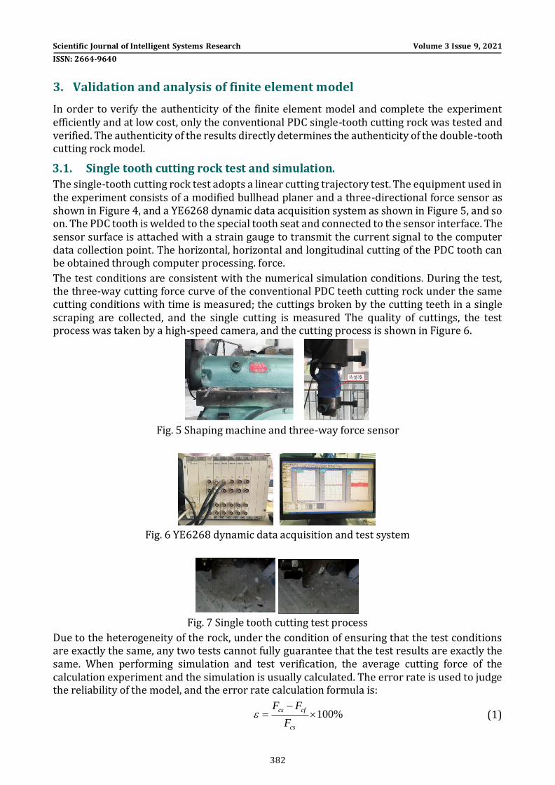
The single-tooth cutting rock test adopts a linear cutting trajectory test. The equipment used in the experiment consists of a modified bullhead planer and a three-directional force sensor as shown in Figure 4, and a YE6268 dynamic data acquisition system as shown in Figure 5, and so on. The PDC tooth is welded to the special tooth seat and connected to the sensor interface. The sensor surface is attached with a strain gauge to transmit the current signal to the computer data collection point. The horizontal, horizontal and longitudinal cutting of the PDC tooth can be obtained through computer processing. force.
The test conditions are consistent with the numerical simulation conditions. During the test, the three-way cutting force curve of the conventional PDC teeth cutting rock under the same cutting conditions with time is measured; the cuttings broken by the cutting teeth in a single scraping are collected, and the single cutting is measured The quality of cuttings, the test process was taken by a high-speed camera, and the cutting process is shown in Figure 6.
Fig. 5 Shaping machine and three-way force sensor
Fig. 6 YE6268 dynamic data acquisition and test system
Fig. 7 Single tooth cutting test process
Due to the heterogeneity of the rock, under the condition of ensuring that the test conditions are exactly the same, any two tests cannot fully guarantee that the test results are exactly the same. When performing simulation and test verification, the average cutting force of the calculation experiment and the simulation is usually calculated. The error rate is used to judge the reliability of the model, and the error rate calculation formula is:
100%cs cf
cs
F F
F
(1)

Scientific Journal of Intelligent Systems Research Volume 3 Issue 9, 2021
ISSN: 2664-9640
383
In the formula: csF is the average cutting force of the test and cfF the average cutting force of
the simulation. Usually the result is less than 15% which is reliable.
The cutting force and average cutting force obtained from single tooth test and simulation are shown in Figure 7. The test average cutting force is 900.88N, and the simulated average cutting force is 833.44N. The error rate between calculation experiment and numerical simulation is 7%, so it can be proved that the simulation model is completely reliable.
Fig. 8 Variation diagram of single tooth cutting test and simulation cutting force
4. Analysis of composite cutting model results
After carrying out the simulation model calculation of conventional PDC single tooth, tapered PDC tooth, tapered tooth and conventional tooth compound cutting, the characteristics of cutting force, crushing specific work, and cutting tooth force were compared, and the characteristics of different properties were analyzed and summarized. The impact of the exposed height under the rock on the rock breaking performance.
4.1. Force cloud
The cutting trajectory is the most intuitive reflection of the rock breaking method and effect. The advantage of simulation is that the differences in various places can be seen intuitively and clearly. Figure 8 shows the Mises stress cloud diagram of the rock. It is not difficult to see that the cutting trajectories of the three types of rocks are significantly different under the same conditions. It can be clearly seen from the diagrams (1), (2), (3) and (4) in Fig. 8 that when the cutting depth of the conventional tooth remains unchanged, as the cutting depth of the conical tooth increases, the pre-treatment of the rock caused by the conical tooth is The more obvious the damage, it will cause the rock in the middle of the bottom to break, which is conducive to the cutting of conventional teeth.
It can be clearly seen from (4), (5), (6) and (7) in Figure 8 that when the cutting depth of the tapered tooth remains unchanged, as the cutting depth of the conventional tooth increases, the cutting area gradually increases, which is beneficial to The cutting and breaking of the rock.
In homogeneous sandstone, the stress distribution of rock is relatively regular; in gravel sandstone, the stress distribution of rock is very messy, and most of them are concentrated in the harder "gravel" area; in soft and hard interlaced rocks, the stress distribution is mainly concentrated in the hard rock area , And the pre-crushing effect of the conical teeth on the hard rock is obvious, which will cause a large amount of blocky debris, which is conducive to the crushing of the rock.

Scientific Journal of Intelligent Systems Research Volume 3 Issue 9, 2021
ISSN: 2664-9640
384
(1)The cutting depth of the bevel tooth is 0.5mm, and the cutting depth of the conventional
tooth is 2mm
(2)The cutting depth of the bevel tooth is 1mm, the cutting depth of the conventional tooth is
2mm
(3)The cutting depth of the bevel tooth is 1.5mm, the cutting depth of the conventional tooth
is 2mm
(4)The cutting depth of the bevel tooth is 2mm, and the cutting depth of the conventional
tooth is 2mm
(5)The cutting depth of the bevel tooth is 2mm, and the cutting depth of the conventional
tooth is 0.5mm
a b
a b
a b c
a
b

Scientific Journal of Intelligent Systems Research Volume 3 Issue 9, 2021
ISSN: 2664-9640
385
(6)The cutting depth of the bevel tooth is 2mm, and the cutting depth of the conventional
tooth is 1mm
(7)The cutting depth of bevel teeth is 2mm, and the depth of cutting teeth is 1.5mm
(a)Mean sandstone(b)Gravel sandstone(c)Staggered rock
Fig. 9 Mises stress nephogram of rock
4.2. Cutting force
Cutting force is the opposite force to cutting speed, which directly affects the efficiency of cutting rock-breaking. The smaller the cutting force, the higher the cutting efficiency. Figure 9 shows the average cutting force change curve of tapered teeth and conventional teeth at different cutting depths in homogeneous sandstone, gravel sandstone, and soft and hard interlaced rocks during compound cutting. In Figure 9, Z represents the cone For teeth, P represents conventional teeth, and the number behind represents the depth of cut. It can be seen from Figure 9 that in average sandstone, gravel sandstone, and soft and hard interlaced rock, the cutting depth of the tapered tooth is 2mm, and the cutting depth of the conventional tooth is 0.5mm, the cutting force is the smallest and the cutting efficiency is the highest, mainly due to the tapered tooth pair The rock causes pre-fragmentation and pre-damage, which reduces the difficulty of cutting conventional teeth and reduces the effective cutting area. In homogeneous sandstone, the cutting depth of conical teeth is 1.5mm, and the cutting depth of conventional teeth is 2mm. The efficiency is the lowest. In conglomerate sandstone and soft and hard interlaced rocks, the efficiency of conical teeth and conventional teeth is the lowest when the cutting depth is 2mm.
Fig. 10 Variation curve of mean cutting force of double teeth
b
a b
Scientific Journal of Intelligent Systems Research Volume 3 Issue 9, 2021
ISSN: 2664-9640
386
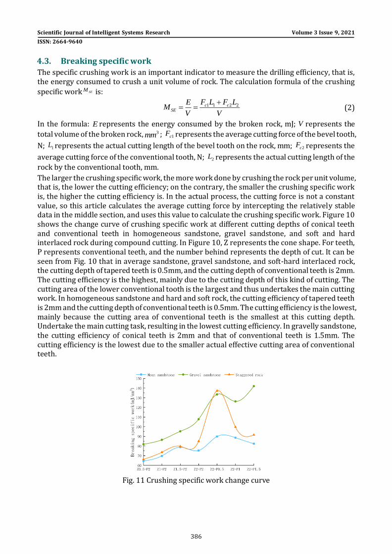
4.3. Breaking specific work
The specific crushing work is an important indicator to measure the drilling efficiency, that is, the energy consumed to crush a unit volume of rock. The calculation formula of the crushing
specific work SEM is:
1 1 2 2c cSE
F L F LEM
V V
(2)
In the formula: E represents the energy consumed by the broken rock, mJ; V represents the
total volume of the broken rock, 3mm ; 1cF represents the average cutting force of the bevel tooth,
N; 1L represents the actual cutting length of the bevel tooth on the rock, mm; 2cF represents the
average cutting force of the conventional tooth, N; 2L represents the actual cutting length of the
rock by the conventional tooth, mm.
The larger the crushing specific work, the more work done by crushing the rock per unit volume, that is, the lower the cutting efficiency; on the contrary, the smaller the crushing specific work is, the higher the cutting efficiency is. In the actual process, the cutting force is not a constant value, so this article calculates the average cutting force by intercepting the relatively stable data in the middle section, and uses this value to calculate the crushing specific work. Figure 10 shows the change curve of crushing specific work at different cutting depths of conical teeth and conventional teeth in homogeneous sandstone, gravel sandstone, and soft and hard interlaced rock during compound cutting. In Figure 10, Z represents the cone shape. For teeth, P represents conventional teeth, and the number behind represents the depth of cut. It can be seen from Fig. 10 that in average sandstone, gravel sandstone, and soft-hard interlaced rock, the cutting depth of tapered teeth is 0.5mm, and the cutting depth of conventional teeth is 2mm. The cutting efficiency is the highest, mainly due to the cutting depth of this kind of cutting. The cutting area of the lower conventional tooth is the largest and thus undertakes the main cutting work. In homogeneous sandstone and hard and soft rock, the cutting efficiency of tapered teeth is 2mm and the cutting depth of conventional teeth is 0.5mm. The cutting efficiency is the lowest, mainly because the cutting area of conventional teeth is the smallest at this cutting depth. Undertake the main cutting task, resulting in the lowest cutting efficiency. In gravelly sandstone, the cutting efficiency of conical teeth is 2mm and that of conventional teeth is 1.5mm. The cutting efficiency is the lowest due to the smaller actual effective cutting area of conventional teeth.
Fig. 11 Crushing specific work change curve

Scientific Journal of Intelligent Systems Research Volume 3 Issue 9, 2021
ISSN: 2664-9640
387
4.4. Cutting force fluctuation
Since the cutting teeth are made of polycrystalline diamond, they are wear-resistant but not impact-resistant. The constantly fluctuating cutting force during the cutting process is an important factor in the damage of the cutting teeth. Therefore, it is necessary to analyze the maximum load on the cutting teeth. The introduced range is the difference between the maximum load on the cutting tooth and the average load. Discussing its value will help analyze and judge the wear life of the cutting tooth. The greater the range, the greater the load fluctuation, which will affect the life of the cutting teeth and should be avoided.
Figure 11 shows the load range curve of the cutting tooth when the conical tooth and the conventional tooth are cut in homogeneous sandstone, gravel sandstone, and soft and hard interlaced rock during compound cutting, respectively. In Figure 11, Z represents the cone For shaped teeth, P represents conventional teeth, and the number behind represents the depth of cut. In average sandstone, when the cutting depth of the conical tooth is 1-1.5mm and the cutting depth of the conventional tooth is 2mm, the load range is the smallest and the service life is the longest.
In gravelly sandstone, when the cutting depth of the conical tooth is 1mm and the cutting depth of the conventional tooth is 2mm, the load difference between the conical tooth and the conventional tooth is approximately equal, and the service life of the cutting tooth is the longest.
In soft and hard rock, when the cutting depth of the conical tooth is 1.5mm and the cutting depth of the conventional tooth is 2mm, the load difference of the two teeth is extremely equal, which means that the load fluctuation is the most stable and the cutting tooth has the longest service life.
(a)Mean sandstone
(b)Gravel sandstone

Scientific Journal of Intelligent Systems Research Volume 3 Issue 9, 2021
ISSN: 2664-9640
388
(c)Staggered rock
Fig. 12 Cutter load range curve
5. Conclusion
In soft and hard rock, when the cutting depth of the conical tooth is 1.5mm and the cutting depth of the conventional tooth is 2mm, the load difference of the two teeth is extremely equal, which means that the load fluctuation is the most stable and the cutting tooth has the longest service life.
1) The composite cutting model of conical teeth and conventional PDC teeth is established, and the rock fragmentation during composite cutting in average sandstone, gravel sandstone, and soft and hard interlaced rocks is revealed through simulation.
2) The deeper the cutting depth of the tapered tooth, the better the pre-crushing effect on the rock, the greater the cutting force, the greater the crushing power and the lower the efficiency.
3) Through simulation, the maximum load range curves of conventional teeth and conical teeth in average sandstone, gravel sandstone, and soft and hard interlaced rocks, the change curve of crushing specific work, and the change curve of average cutting force, are conical teeth and Conventional PDC gears are mixed on the same track to provide data support.
4) In homogeneous sandstone and pebbly sandstone, it is recommended to use composite cutting depth of cut, tapered tooth cutting depth of 1mm, conventional tooth cutting depth of 2mm; in soft and hard rock, it is recommended to use composite cutting depth of cut, tapered The cutting depth of the tooth is 1.5mm, and the cutting depth of the conventional tooth is 2mm.
References
[1]. Wilmot G M. Innovative Cutting Structure Improves Stability and Penetration Rate of PDC Bits Without Sacrificing Durability. SPE/IADC 39310,1988
[2]. LI Bai-sheng,SUN Ming-guang. New PDC bit design for gravel bearing and hard and soft interlaced formations. China Petroleum Machinery,2004(09): 32-34
[3]. ZHOU Long-chang,WU Tian-qian, LV Cong-rong. Development and field test of new diamond bit for composite drilling. Petroleum Drilling Techniques,2004(02):42-43.
[4]. LIU Ya-jun, WANG Xiao-peng, WANG Kun-jian,et al. Optimization design and application of new drill bit in SZ36-1 Oilfield.Fault-block Oil & Gas Field,2011,18(05):669-671.
[5]. YANG Shun-hui. Development and Laboratory Tests Evaluation of PDC Bit with Conical Cutter. China Petroleum Machinery, 2015,43(02):14-17.
[6]. WANG Wei-tao. Design and Test of a New PDC Bit with Tapered Auxiliary Cutter for Heterogeneous Formations. Petroleum Drilling Techniques, ,2018,46(02):58-62.
[7]. LIU Zhong, HOU Hui-hui, Hu Wei. An Experimental and Numerical Simulation Study on Rock Cutting Based on Pre-Breaking. China Petroleum Machinery, 2019,47(12):38-43.

Scientific Journal of Intelligent Systems Research Volume 3 Issue 9, 2021
ISSN: 2664-9640
389
[8]. CAO Ji-fei. Research and application of key technology of drilling speed increase in strongly consolidated sandy conglomerate formation. Western Exploration Project, 2019,31(03):16-18.
[9]. DETOURNAYE, RICHARDT, SHEPHERDM. Drilling responseof drag bits: theory and experiment. International Journal of Rock Mechanics and Mining Sciences, 2008, 45(8): 1347–1360.
[10]. ZHOUY, JAIMEMC, GAMWOIK. Modeling groove cutting inrocks using finite elements. ARMA-11-209, 2011.
[11]. MARTINEZIR, FONTOURAS, INOUEN, et al. Simulation of single cutter experiments in evaporites through finite element method. SPE 163504, 2013.
[12]. ZOU De-yong, CAI Huan. Experiment on effect of cutter parameters of PDC bit on rate of penetration[J]. Journal of China University of Petroleum,2009,33(05):76-79.
[13]. ZU Xiao-hua, LI Hai. Numerical simulation of rock breaking efficiency of PDC cutters. Journal of Basic Science and Engineering,2015,23(01):182-191.
[14]. Zhao Dong-peng, MA Shan-shan, NIU Tong-jian, et al. Development of nonplanar polycrystalline diamond composites for petroleum drilling. Diamond and Abrasives Engineering,2017,37(06):49-52.