numerical study of heat transfer in a finned double pipe ...eprints.manipal.edu/142798/1/wjms 2015...
TRANSCRIPT

ISSN 1 746-7233, England, UKWorld Journal of Modelling and Simulation
Vol. 11 (2015) No. 1, pp. 43-54
Numerical study of heat transfer in a finned double pipe heat exchanger
Shiva Kumar∗, K. Vasudev Karanth, Krishna Murthy
Dept of Mechanical Engg, MIT, Manipal, India
(Received September 20 2013, Accepted October 13 2014)
Abstract. In the present study the performance of a concentric tube heat exchanger is analyzed with passiveheat transfer technique. The performance of the heat transfer process in a given heat exchanger is determinedfor three different longitudinal fin profiles, rectangular, triangular and parabolic. Numerical analysis wascarried out in a parallel flow double pipe heat exchanger for the above profiles for varied mass flow conditionsboth in the inner and outer tube. Base width and height of the fin were kept constant for all the three types.Simulated results indicated an enhancement in the heat transfer rate for a finned tube compared to the unfinnedone. Among the different configurations, fin with rectangular profile showed marginal improvement overtriangular and concave parabolic profiles in terms of heat transfer characteristics. For a constant value ofmcc = 0.02kg/s and varying mch, rectangular finned tubes showed an average improvement of 6.1% overthe triangular and 9.2% over parabolic finned tube. Similarly For a constant value of mch = 0.02kg/s andvarying mcc, it showed an improvement by 2 and 5% over the triangular tube and parabolic finned tuberespectively Fins with concave parabolic profiles exhibited minimum pressure drop and has reduced by 38%and 65% compared to the triangular and rectangular finned tube.
Keywords: double pipe heat exchanger, triangular fins, parabolic fins, fin effectiveness, pressure drop
1 Introduction
Heat transfer enhancement in a heat exchanger is getting industrial importance because it gives the oppor-tunity to reduce the heat transfer area for the heat exchanger. Increase in the heat exchanger performance canhelp to make energy, material and cost saving related to a heat exchange process. Double pipe heat exchangersare the simplest devices in which heat is transferred from the hot fluid to the cold fluid through a separatingcylindrical wall. They are primarily adapted to high temperature and high pressure applications due to theirsmall diameters. They are fairly cheap, but the amount of space they occupy is relatively high compared to theother types. Hence for the given design and length of the heat exchanger heat transfer enhancement in a doublepipe heat exchanger is possibly achieved by several methods. These techniques are divided into active and pas-sive techniques. Active methods involve some external input for the enhancement of heat transfer like inducedvibrations, injection and suction of fluids and jet impingement etc. Another method is the passive methodwithout the stimulation by external power such as surface coating, surface roughness and extended surfaces.Chen et al.[4] used dimples as the heat transfer modification on the inner tube. Bhuiya et al.[3], Eiamsan etal.[5] and Liao et al.[12] used circular tube equipped with perforated twisted tape inserts with different con-figurations to enhance the heat transfer through the tube. In order to intensify the heat transfer from the heatexchanger surface to fluid, it is possible to increase convection coefficient (by growing the fluid velocity),widen temperature difference between surface and fluid or increase the surface area across which convectionoccurs. Extended surfaces, in the form of longitudinal or radial fins are common applications where the needto enhance the heat transfer between a surface and an adjacent fluid exists.Several researchers used extendedsurfaces for the enhancement in the heat transfer[2, 9, 11, 15].
∗ Corresponding author. E-mail address: shiva [email protected].
Published by World Academic Press, World Academic Union

44 S. Kumar & K. Karanth & K. Murthy: Numerical study of heat transfer
Masliyah et al.[13] studied heat transfer characteristics for a laminar forced convection fully developedflow in an internally triangular finned circular tube with axially uniform heat flux using a finite elementmethod. For a given fin geometry, the Nusselt number based on inside tube diameter was higher than thatfor a smooth tube. Also, it was found that for maximum heat transfer there exists an optimum fin numberfor a given fin configuration. Agarwal et al.[1] studied Laminar flow and heat transfer magnitudes in a finnedtube annulus. Pressure drop and heat transfer characteristics of the fins are obtained in the periodically fullydeveloped region by varying geometric and flow parameters. Geometric parameters are annulus radius ratio(0.3 to 0.5), fin height/annular gap (0.33 to 0.67) and fin spacing/annular gap (2 to 5). Flow parameters areReynolds number (100 to 1000) and Prandtl number (1 to 5). Comparisons are made with a plain tube annulushaving the same length, heat transfer surface area, volume flow rate, and Reynolds number. They observedthat at Prandtl numbers less than 2, the use of fins may not be justified because the increase in pressuredrop is more pronounced than the increase in heat transfer. At a Reynolds number of 1000 and A Prandtlnumber of 5, the heat transfer increases by a factor of 3.1, while the pressure drop increases by a factor of 2.3.mch : Mass flow rate of the hot fluid(kg/s).mcc : Mass flow rate of the cold fluid (kg/s).ε : Fin effectiveness.hannulus : Effective heat transfer coefficient in the annulus side.hnormal : Heat transfer coefficient in the annulus side without the fins.
Soliman et al.[17] studied steady, laminar, forced convection heat transfer in the thermal entrance regionof internally finned tubes for the case of fully developed hydrodynamics. Results were presented for 16 ge-ometries including the local Nusselt number and developing length corresponding to each boundary condition.These results indicate that internal finning influences the thermal development in a complicated way, whichmakes it inappropriate to extend the smooth tube results to internally finned tubes on a hydraulic diameterbasis. Totala et al.[19] conducted experiments in a double pipe heat exchanger by providing threads in the innerpipe. They observed that Nusselt number, heat transfer coefficient were increased for the threaded pipe. Butthe pumping power required also increased compared to the plain tube. Khannan et al.[10] studied the heattransfer through a double pipe heat exchanger with annular fins. Three different configurations annular ring,spiral rod and rectangular projection were considered on the outside surface of the outer tube. Experimentswere done with varied mass flow rates. It was observed that heat transfer rate was increased for a finned tube.Fin with annular ring showed better performance than other methods. Nagarani et al.[16] used circular andelliptical annular fins as a heat enhancement devise in a double pipe heat exchanger. It was observed that heattransfer rate was higher in elliptical fins than circular fins. Heat transfer coefficient depends on the fin spacing,flow condition and fluid properties. Fin efficiency was higher for elliptical fins. Mir et al.[14] studied Numericalsimulation of the steady, laminar, forced convection heat transfer in the finned annulus for the case of fullydeveloped incompressible flow corresponding to thermal boundary condition of uniform heat input per unitaxial length with peripherally uniform temperature at any cross section. Various heat transfer and fluid flowcharacteristics were investigated for a range of values of the ratio of radii of inner and outer pipes, fin heightand number of fins. The results calculated are in good comparison with the correlation results with consider-able gain in the computational time. Syed et al.[18] numerically simulated the laminar convection flow in thefully developed region of finned double pipe subjected to constant heat flux boundary conditions. They founda significant enhancement in heat transfer rate and also nusselt number. For small number of fins fin geome-tries like fin height, ratio of radii, and half fin angle were found to be less influential. Iqbal et al.[8] investigatedoptimal configuration of finned annulus with parabolic, triangular and trapezoidal fins using finite elementmethods and genetic algorithms. They concluded that no single fin shape is best in all situations and for allcriteria. Zhang et al.[20] studied heat transfer enhancement for shell side of a double-pipe heat exchanger withhelical fins and pin fins, the three-dimensional velocity components for the shell side with and without pin finswere measured experimentally by using laser Doppler anemometer (LDA) under cylindrical coordinate sys-tem and the fluid flow characteristics. The results showed that, for the shell side only with helical fins at largepitch, there was a pair of vortex near the upper and lower edge of the rectangular cross section the weakestsecondary flow occurred at the center. By pin fins being installed, the three-dimensional velocity componentsin the helical channel were strongly changed. Patel et al.[6] simulated the industrial experimental results of
WJMS email for contribution: [email protected]

World Journal of Modelling and Simulation, Vol. 11 (2015) No. 1, pp. 43-54 45
a double pipe heat exchanger using ANSYS14-CFX. Results indicated heat transfer, pressure drop, pumpingpower increased with mass flow rate whereas friction factor decreased.
Optimization aims at improving the performance with lowering the fin mass by means of changing theshape of the fin. The fin shape modification influences not only the mass of the heat exchanger, but also af-fects the flow direction that causes the temperature changes on the fin contact surfaces. For heat exchangers,built with many fins and designed for real industry, it is important to pay attention to and calculate the heattransfer considering the fluid flow and flow paths. The resistance of the body results in a pressure drop. Thefin and tube surface orientation also modifies the resistance of the body that results in a pressure drop. Hencea comparison study of heat transfer characteristics using different configurations of fins is very essential. Lit-erature survey reveals that most of the analysis was done by considering constant heat flux or constant walltemperature boundary condition. Literature regarding the numerical study of enhancement in heat transfercharacteristics using different configurations of internal longitudinal fins for a double pipe heat exchangerwith conjugate heat transfer is still scare. Hence the present work aimed at comparison of heat transfer char-acteristics using different fin profiles for a double pipe heat exchanger under various operating conditions toevolve with the best possible configuration. Three different configurations namely rectangular, triangular andconcave parabolic were selected. Base width,height and number of the fins were kept identical for the sake ofcomparison. Numerical simulation was done using commercial CFD package[7]. Heat transfer characteristicslike temperature variation, heat transfer rate, and heat transfer coefficient and fin effectiveness for the abovesaid models were compared and are presented. The paper has been organized into 5 sections. Section 1 dealswith introduction, Section 2 describes the experimental set up and experimentation procedure. Section 3 de-scribes the numerical scheme followed for the double pipe heat exchanger for various fined configurations.Section 4 discusses the results and in Section 5 conclusions were drawn.
2 Experimental set up and experimentation
Fig .1 shows the experimental set up of the concentric tube double pipe heat exchanger. It consists of innertube made of copper where in hot water flows from a geyser attached to it. Cold water flows in the annuluswhich can be admitted at any one of the ends enabling the heat exchanger to run as a parallel or as a counterflow exchanger. This can be done by operating the valves provided. Specifications of the heat exchanger arementioned in Tab. 1. Temperatures of the fluid can be measured using thermocouples with digital display.Flow rates of hot and cold water can be measured by rotometers connected to the pipes. Outer tube is providedwith insulation to minimize the heat losses to the surroundings. The inlet temperature of the hot fluid wasmaintained at 332K and the cold fluid at 303K. Experiments were conducted for parallel flow arrangement atvarious mass flow rates of hot water (mch) ranging from 0.02kg/s to 0.1kg/s with an increment of 0.02kg/sat each time keeping the mass flow rate of cold water (mcc) through the annulus constant at 0.02kg/s. Rangeof the Reynolds’s number in the present study was 3000 to 20000. Outlet temperatures of the hot water andcold water were noted each time. Similarly the experiments were repeated by changing the cold water flowrates keeping the hot water flow rate constant at 0.02kg/s. The results obtained were compared with resultsobtained from CFD model.
Table 1. Specifications of the double pipe heat exchanger
S.No Specifications Dimension (mm)1 Inner diameter 9.52 Thickness of the inner tube 1.53 Inner diameter of the outer tube 28.54 Thickness of the outer tube 25 Length of the heat exchanger 1500
WJMS email for subscription: [email protected]

46 S. Kumar & K. Karanth & K. Murthy: Numerical study of heat transfer
Fig. 1. Photograph of the experimental test rig
3 Numerical scheme
3.1 Double pipe heat exchanger without fins
The geometric model of the double pipe heat exchanger was constructed using work bench in ANSYS14 environment. The complete domain consists of 157254 Elements. Grid independence test was performedto check the validity of the quality of the mesh on the solution as shown in the Fig. 2. Further refinement didnot change the result by more than 0.9% which was taken as the appropriate mesh quality for computation.Inlet temperature and mass flow rate of the cold and hot fluid was specified. At the outlet, a pressure outletboundary is enforced. Pressure velocity coupling was resolved using SIMPLEC algorithm with a skewnesscorrection factor of 1. For pressure linear discretization was used. For momentum turbulent kinetic energy andturbulent dissipation rate with power law scheme was used. For the energy equation second order upwind wasused. Conservation equations were solved for the control volume to yield the velocity and temperature fieldsfor the water flow in the heat exchanger. Convergence was affected when residuals fell below 10−3 in thecomputational domain. A sample convergence plot is shown in the Fig. 3 Simulations were done by changingthe mass flow rates of hot fluid as well as cold fluid as discussed in the previous section.A comparison ofnumerically simulated and experimental outlet temperatures of the cold water is as shown in Tab. 2. It revealsthat the average error for constant mcc and varying mch is 0.157% and for constant mch varying mcc it is0.183% which is within the acceptable limits. Hence the use of CFD modeling for studying the heat transfercharacteristics in a double pipe heat exchanger can be employed with confidence.
309.4
309.6
309.8
310
310.2
310.4
120643 124610 130511 157254 167310 178243
Tem
pera
ture
Number of elements
Fig. 2. Variation of cold water outlet temperature with number of elements
WJMS email for contribution: [email protected]

World Journal of Modelling and Simulation, Vol. 11 (2015) No. 1, pp. 43-54 47
Fig. 3. Sample of Residual convergence plot for the double pipe heat exchanger
Table 2. Comparison of experimental and CFD simulated results for unfinned the double pipe heat exchanger
S.NoExperimentalcondition
Mass flowrate (kg/s)
Experimental measured cold water outlettemperature (K)
CFD simulatedcold water outlet temperature (K)
Relativeerror (%)
1mcc constant at0.02 kg/s andmch varying
0.02 309.8 310.34 0.175
2 0.04 311.05 311.5 0.1613 0.06 311.4 311.97 0.1834 0.08 312.6 312.22 0.1235 0.1 312.2 312.45 0.144
6mch constant at0.02 kg/s andmcc varying
0.02 309.8 310.34 0.175
7 0.04 307.5 308 0.1638 0.06 306.2 306.92 0.2369 0.08 305.6 306.28 0.22210 0.1 305.4 305.83 0.140
3.2 Rectangular finned double pipe heat exchanger
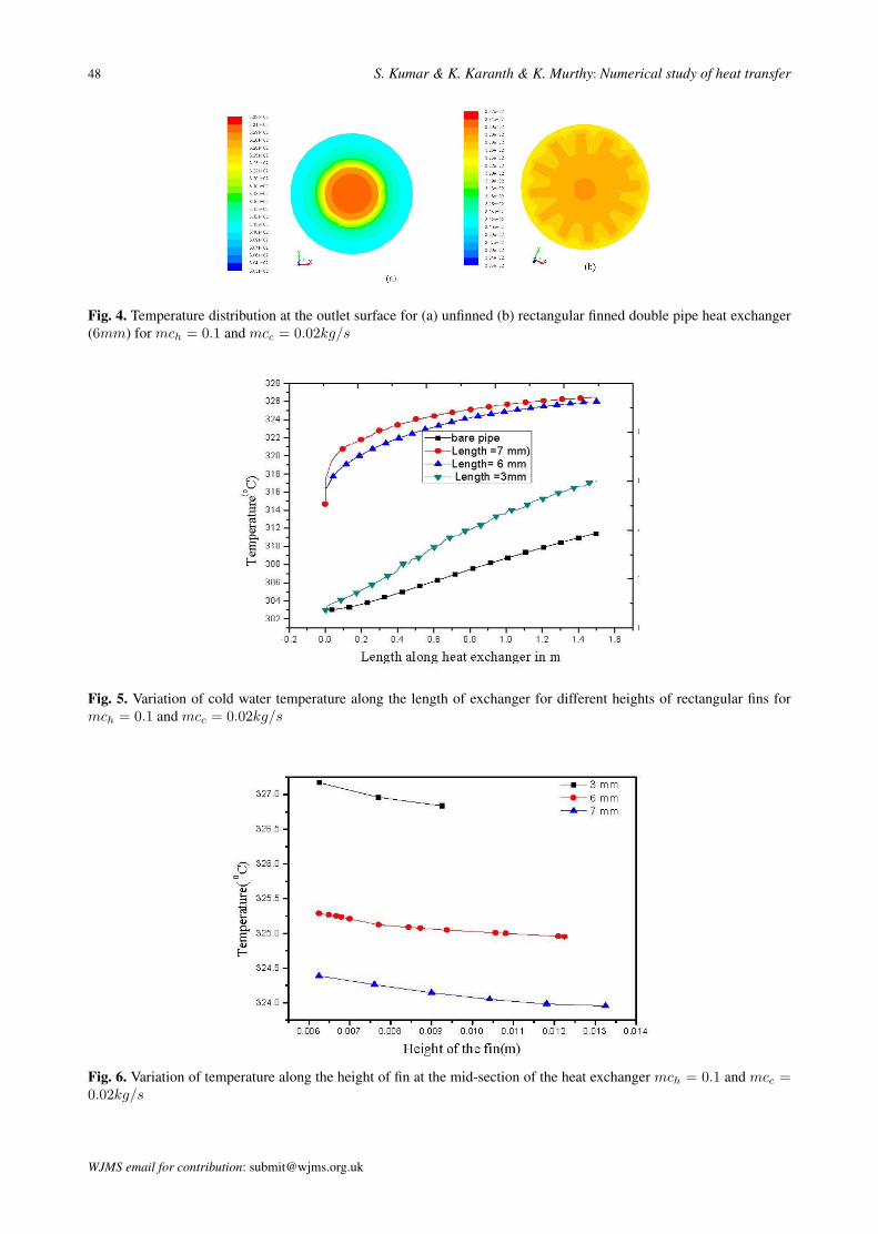
A double pipe heat exchanger with rectangular longitudinal fins was modeled in the Ansys work benchenvironment. Base width of the fin was 2mm (18 degrees) kept constant throughout the study. Simulationwas done using different fin heights 3mm, 6mm and 7mm. 12 fins were placed circumferentially aroundthe thickness of the inner tube which remained constant throughout the study. Simulation was carried outfor various mass flow rates of cold and hot water. For mch = 0.1kg/s and mcc = 0.02kg/s temperaturedistribution at the outlet for both unfinned and finned (height = 6mm) heat exchanger is shown in Fig .4which clearly indicates the increase in the average temperature in the annulus for a finned tube. Annulus fluidtemperature along the length of heat exchanger was plotted for different fin heights and is as shown in Fig .5. Itcan be observed that the temperature rise for the finned heat exchanger is more than that of the unfinned type.As the fin height increases the average water temperature increased. But on comparing the temperature risefor different fin heights, as the height increases, rise in average temperature was found to be lower. Also thecurve shows that the temperature rise along the length of exchanger is gradual and not steep. Fig .6 representthe temperature plot along the vertical length at the center of the fin for 3mm, 6mm and 7mm height fins ata midsection of the heat exchanger. Fin tip temperature for 3mm, 6mm and 7mm height fins are 326.84, 325and 323.95K respectively. It indicates that there was a decrease of temperature by 1.84K when the heightwas increased from 3mm to 6mm and a decrease of 1.05K when the height was increased from 6mm to7mm which indicates the reduced fin performance on increasing the fin height. Simultaneously increasing thefin height increases the weight of the finned assembly. Hence an optimum fin height of 6mm was chosen forfurther comparison between different profiles for fins.
WJMS email for subscription: [email protected]
48 S. Kumar & K. Karanth & K. Murthy: Numerical study of heat transfer
Fig. 4. Temperature distribution at the outlet surface for (a) unfinned (b) rectangular finned double pipe heat exchanger(6mm) for mch = 0.1 and mcc = 0.02kg/s
Fig. 5. Variation of cold water temperature along the length of exchanger for different heights of rectangular fins formch = 0.1 and mcc = 0.02kg/s
Fig. 6. Variation of temperature along the height of fin at the mid-section of the heat exchanger mch = 0.1 and mcc =0.02kg/s
WJMS email for contribution: [email protected]

World Journal of Modelling and Simulation, Vol. 11 (2015) No. 1, pp. 43-54 49
4 Results and discussions
Geometrical modeling of the heat exchanger was constructed by changing the fin configuration to tri-angular and concave parabolic profiles keeping the fin base width, height and number of fins constant asdiscussed in Section 3. Fig. 7 shows the different fin configurations undertaken in the present study. Simula-tion was done for different mass flow rates of hot water through the inner tube for a constant cold water flowrate of 0.02kg/s in the annulus. Fig .8 indicates the temperature plot of all fin profiles with mch = 0.1kg/sand mcc = 0.02kg/s. It depicts that the cold water outlet temperature for the finned tube is higher than thebare tube. Fins promote boundary layer separation of the fluids and disturb the whole bulk flow field insidecircular tubes. Separation and restarting of the boundary layers increases the heat transfer rate. It can be fur-ther noted that the bulk of the fluid layer is being disturbed the rise of temperature is also uneven along thelength of the tube as shown in Fig. 8. Temperature for triangular and parabolic profile s is slightly higherthan the rectangular at the entry of the heat exchanger, and as fluid progresses along the length of the heatexchanger temperature for the rectangular profile increases sharply than the other two types and at the outletit is marginally higher than for triangular and parabolic type. The fin shape modification influences not onlythe mass of the heat exchanger, but also affects the flow direction that causes the temperature changes on thefin contact surfaces.
Fig. 7. Different types of finned configurations (a) triangular, (b) rectangular and (c) concave parabolic
Fig. 8. Variation of temperature along the length of heat exchanger for different fin profiles at mch = 0.1 and mcc =0.02kg/s
WJMS email for subscription: [email protected]

50 S. Kumar & K. Karanth & K. Murthy: Numerical study of heat transfer
Fig. 9 indicates the plot of cold water outlet temperature Vs mass flow rates of the hot water. The outlettemperature for the rectangular fin is 0.1% and 0.2% more that of triangular and parabolic shape for thehighest mass flow rate of hot water. Fig. 10 shows temperature rise along the length for a particular value ofmch = 0.02kg/s and mcc = 0.1kg/s. It can be revealed that rise in the temperature is higher for a finnedtube than the unfinned one. In case of finned tube, the rise is not uniform and smooth as the entire flow field isbeing disturbed along the length. Rectangular finned tubes show a marginal improvement over the other types.
Fig. 9. Variation of cold water outlet temperature with mass flow rates of hot water
Fig. 10. Variation of temperature along the length of heat exchanger for different fin profiles at mch = 0.1 and mcc =0.02kg/s
Fig. 11 shows the variation of outlet temperature of cold water for varying mass flow rates of cold waterwith mass flow rate of hot water being fixed. It indicates as the mass flow rate increases the outlet temperaturedecreases for all profiles. This is because for a fixed value of mch heat energy dissipated from the inner tuberemains constant and hence as mcc is increased heat transfer rate is being increased due to the increased
WJMS email for contribution: [email protected]

World Journal of Modelling and Simulation, Vol. 11 (2015) No. 1, pp. 43-54 51
turbulence, but the retention time of the fluid in the exchanger will be reduced which decreases the cold wateroutlet temperature. Drop in outlet temperature or the rectangular profile is marginally lesser than the other twotypes showing its better performance.
Fig. 11. Variation of cold water outlet temperature with varying mass flow rates of cold water
Tab. 3 indicates the heat transfer rate for different simulated conditions for the finned and unfinnedtubes. It can be revealed that heat transfer rate increases with the increase in mass flow rate and finned tubesshow higher value than the unfinned condition. For a constant value of mcc = 0.02kg/s and varying mch,rectangular finned tubes showed an average improvement of 6.1% over the triangular and 9.2% over parabolicfinned tube. Similarly For a constant value of mch = 0.02kg/s and varying mcc, it showed an improvementby 2 and 5% over the triangular tube and parabolic finned tube respectively.
Table 3. Comparison of experimental and CFD simulated results for unfinned the double pipe heat exchanger
S.No Condition Mass flowrate (kg/s)
Unfinnedtube (W )
rectangularfinned tube(W )
triangularfinnedtube (W )
concave parabolic finnedtube (W )
1mcc constant at0.02 kg/s andmch varying
0.02 621 1069 1023 1000
2 0.04 718 1430 1348 13113 0.06 759 1620 1515 14634 0.08 784 1741 1623 15655 0.1 800 1828 1700 1619
6mch constant at0.02 kg/s andmcc varying
0.02 621 1069 1023 1000
7 0.04 841 1372 1284 12708 0.06 992 1541 1487 14069 0.08 1102 1589 1507 149310 00.1 1187 1680 1664 1554
Fig. 12 shows the variation of annulus heat transfer coefficient for different varied mcc keeping mchconstant at 0.02kg/s. It is observed that annulur heat transfer coefficient is found to be reduced for finnedstructure since effective heat transfer coefficient is related to the efficiency of the fin as Hannular =
WJMS email for subscription: [email protected]

52 S. Kumar & K. Karanth & K. Murthy: Numerical study of heat transfer
Finefficiency × hnormal. Further on comparing the values for different fin profiles it is observed that rect-angular profiles the heat transfer coefficient is slightly higher than the others at all mass flow rate conditions.
Fig. 12. Variation of annulus heat transfer coefficient with varying mass flow rates of cold water
Fig. 13 represents fin effectiveness for various types of fins under different conditions. Fin Effectivenesswas calculated by the simple relation fin effectiveness, ε = Qwithfin
Qwithoutfin. For a constant value of mcc of 0.02kg/s,
as mch was increased the effectiveness of the fins increased and rectangular fins showed highest effectivenessamong the different types. Similarly for a constant mch and as mcc are varied fin effectiveness decreasesas seen in the graph.The rise in temperature for varying mcc decreases for a finned tube compared with theunfinned one. Athigher mass flow rates the flow field is being disturbed severely when compared to the baretube. Hence heat transfer capability of the fins decreases causing reduction in fin effectiveness. Hence in orderto have a better performance by the fins for heating a liquid flowing in the annulus region, mass flow rate ofliquid in the annulus should be minimum and mass flow rate of hot liquid flowing inside the inner tube shouldbe maximum.
Fig. 13. Variation of fin effectiveness with varying mass flow rates of cold water and hot water
WJMS email for contribution: [email protected]

World Journal of Modelling and Simulation, Vol. 11 (2015) No. 1, pp. 43-54 53
Fig. 14 represents the pressure drop variation for unfinned and the finned tube for various mass flow ratesof cold fluid. It can be seen that pressure drop for unfinned tube is lesser than the finned tube. In case of afinned tube minimum pressure drop was observed in case of a fin with parabolic shape and highest for thefin with rectangular shape. The pressure drop for a concave parabolic shape has reduced by 38% and 65%compared to the triangular and rectangular finned tube.Higher pressure losses increase the pumping power.Since the pressure losses are more in case of rectangular finned tube the pumping power required will bemore when compared to the triangular and parabolic finned tube. Marginal reduced performance of parabolicfinned tubes is compensated by reduced weight and reduced pressure losses. Considering all these factorsconcave parabolic fins are preferred over the other types since required pumping power and weight of thefinned structure will be reduced with sacrifice of a marginal benefit of heat transfer characteristics.
Fig. 14. Variation of pressure drop with varying mass flow rates of cold water
5 Conclusion
In the present study numerical simulation of finned double pipe heat exchanger is done with hot fluidflowing in the inner tube and cold fluid in the annulus. After validating the results for a bare heat exchangerwith the experimental results Simulation was done using rectangular, triangular and concave parabolic finnedconfigurations onthe outer body of inner tube. Results indicated finned configurations show an overall im-provement in the thermal characteristics compared with unfinned one. For better Performance the mass flowrate of the cold fluid should be kept low where as that of the hot liquid should be high. Rectangular finned con-figuration show a marginal improvement over the other in terms of temperature rise, heat transfer rate and heattransfer coefficient. For a constant value of mcc of 0.02kg/s, as mch was increased, the effectiveness of thefins increased and rectangular fins showed highest effectiveness and is 21% and 11.5% higher than parabolicand triangular based fins.Parabolic fins showed minimum pressure drop for all mass flow rates. It has reducedby 38% and 65% compared to the triangular and rectangular finned tube. In addition to this even they providethe advantage of lesser material and hence reduced weight. Hence it can be concluded that parabolic finnedconfiguration can be a better alternative compared to the triangular and rectangular because of reduced pres-sure drop and reduced weight of the finned assembly even though the thermal performance is being marginallyreduced.
Recommendations for the future work: Numerical study of concentric double pipe heat exchanger can beextended by increasing the number of fins as well as by considering different fin profiles. Even the range ofprandtl number can be varied by selecting different fluids flowing in the inner tube and in the annulus to studyits influence on the heat transfer characteristics.
WJMS email for subscription: [email protected]

54 S. Kumar & K. Karanth & K. Murthy: Numerical study of heat transfer
References
[1] A. Agrawal, S. Sengupta. Laminar flow and heat transfer in a finned tube annulus. International journal of heatand fluid flow, 1990, 11(1): 54–59.
[2] A. Antony, M. Ganesan. Flow analysis and characteristics comparison of double pipe heat exchanger using en-hanced tubes. Journal of Mechanical and Civil Engineering, 2014, 7: 16–21.
[3] M. Bhuiya, M. Chowdhury, et al. Heat transfer and friction factor characteristics in turbulent flow through a tubefitted with perforated twisted tape inserts. International Communications in Heat and Mass Transfer, 2013, 46:49–57.
[4] J. Chen, H. Muller-Steinhagen, G. Duffy. Heat transfer enhancement in dimpled tubes. Applied Thermal Engineer-ing, 2001, 21(5): 535–547.
[5] S. Eiamsa, P. Eiamsa, C. Thianpong. Turbulent heat transfer enhancement bycounter/co-swirling flow in a tubefitted with twin twisted tape. Experimental thermal & fluid science, 2009, 34(1): 53–62.
[6] P. Harshit, N. Reena. Performance evaluation and CFD analysis of industrial double pipe heat exchanger. Interna-tional Journal of Emerging Trends in Engineering and Development, 2013, 4(3).
[7] F. Incorporation. Fluent 6.3. 2006.[8] Z. Iqbal, K. Syed, M. Ishaq. Optimal convective heat transfer in double-pipe with parabolic fins. International
Journal of Heat and Mass Transfer, 2011, 54: 5415–5426.[9] D. Kadam. Performance simulation of fin and tube heat exchanger. International journal of educational science
and research, 2012, 2(10).[10] M. Kannan, S. Ramu. Experimental and analytical comparison of heat transfer in double pipe heat exchanger.
International Journal of Mechanical Engineering Applications Research, 2012, 3(3).[11] B. Kundu, P. Das. Performance analysis and optimization of straight taper fins with variable heat transfer coeffi-
cient. International journal of heat and mass transfer, 2002, 45(24): 4739–4751.[12] M. Liao, D. Xin. Augmentation of convective heat transfer inside tubes with 3-d internal extended surfaces &
twisted tape inserts. Chemical Engg, 2000, 78(2): 95–105.[13] J. Masliyah, K. Nandakumar. Heat transfer in internally finned tubes. Journal of heat transfer, 1976, 98(2):
257–261.[14] N. Mir, K. Syed, M. Iqbal. Numerical solution of fluid flow and heat transfer in the finned double pipe. Journal of
Research (Science), 2004, 15(3): 253–262.[15] M. Mon, U. Gross. Numerical study of fin spacing effects in annular finned tube heat exchanger. International
Journal of Heat and Mass Transfer, 2004, 47(8): 1953–1964.[16] N. Nagarani, K. Mayilsamy. Experimental heat transfer analysis on the annular circular and elliptical fins. Inter-
national journal of Engineering Science and Technology, 2010, 2(7): 2839–2845.[17] H. Soliman, A. Feingold. Analysis of fully developed laminar flow in longitudinal internally finned tubes. The
Chemical Engineering Journal, 1977, 14(2): 119–128.[18] K. Syed, M. Ishaq, M. Bakhsh. Laminar convection in the annulus of a double-pipe with triangular fins. Computers
& Fluids, 2011, 44: 43–55.[19] N. Totala, V. Desai, et al. Manufacturing and comparative analysis of threaded tube heat exchanger with straight
tube heat exchanger. International Journal of Engineering and Science, 2014, 4(7): 77–85.[20] L. Zhang, W. Du, et al. Fluid flow characteristics for shell side of double-pipe heat exchanger with helical fins and
pin fins. Experimental Thermal and Fluid Science, 2012, 36: 30–43.
WJMS email for contribution: [email protected]