numerical study of shcramjet combustor characteristic control techniques
DESCRIPTION
http://www.fae-journal.org/paperInfo.aspx?ID=9754 Oblique detonation wave (ODW) stabilized over a ramp or a wedge can be used for combustion in a supersonic combustion chamber. This paper numerically studies the conditions for an ODW to be stabilized over a finite ramp length at different temperature, pressure and Mach number conditions, and examines potential combustor control methods in order to achieve desirable ODW combustor characteristics for a propulsion system. At given operating conditions, ramp length and for a given amount of heat release, attached ODWs can only be stabilized over a certain range of ramp angles. Furthermore, for fixed combustor geometry the ODW induction length can be larger than the available ramp length. Also, either the ODW inclination angle can be too low for complete combustion of the entire inflow mixture or the ODW can impinge on the upper combustor wall when the ODW angle is too large. Both these conditions can have detrimental effects on the coTRANSCRIPT

Frontiers in Aerospace Engineering Volume 2 Issue3, August 2013www.fae-journal.org
Numerical Study of Shcramjet Combustor Characteristic Control Techniques Sudip Bhattrai1, Hao Tang*2
College of Energy and Power Engineering, Nanjing University of Aeronautics and Astronautics 29-Yudao St., Nanjing-210016, Jiangsu, China [email protected]; *[email protected] Received 16July, 2013; Revised 4 August, 2013; Accepted 9 August, 2013; Published 12August, 2013 © 2013 Science and Engineering Publishing Company Abstract
Oblique detonation wave (ODW) stabilized over a ramp or a wedge can be used for combustion in a supersonic combustion chamber. This paper numerically studies the conditions for an ODW to be stabilized over a finite ramp length at different temperature, pressure and Mach number conditions, and examines potential combustor control methods in order to achieve desirable ODW combustor characteristics for a propulsion system. At given operating conditions, ramp length and for a given amount of heat release, attached ODWs can only be stabilized over a certain range of ramp angles. Furthermore, for fixed combustor geometry the ODW induction length can be larger than the available ramp length. Also, either the ODW inclination angle can be too low for complete combustion of the entire inflow mixture or the ODW can impinge on the upper combustor wall when the ODW angle is too large. Both these conditions can have detrimental effects on the combustor performance. The effects of changing the combustor flow properties on the formation of ramp-supported ODWs are examined, in order to analyze the possible methods to obtain desirable combustor characteristics. The possibility of varying the ramp angle for combustor characteristic control is also analyzed. The effects of temperature, pressure and equivalence ratio variations on the ODW induction length and angle, as well as the effects of varying the ramp angle, are analyzed and compared. Results indicate that a coupled combustor characteristic control technique is possible, relying for the most part on variations of physical flow properties and partly on slight variations of the ramp angle.
Keywords
Oblique Detonation Waves; Induction Length; Combustor Flow Control
Introduction
The application of shock induced combustion and detonation waves for propulsion applications in mass
launchers and hypersonic air breathing engines was first studied by Dunlap et al. in Reference [Dunlap et al. 1958]. The early application for oblique detonation wave (ODW) was mainly studied for ram accelerator [Hertzberg et al. 1998, Yungster et al. 1992] where a dual-wedge-shaped body is accelerated to hypersonic speeds through a channel filled with fuel-air mixture. Experimental studies for wedge-stabilized ODWs were carried out in Ref. [Nichols et al. 1959], and later experimental studies on shock-induced combustion and ODW were reported in Ref. [Lehr 1972,Daborah et al. 1991,Desbordes et al. 1995].
Oblique detonation wave engine (ODWE), also called shock-induced combustion ramjet (shcramjet), is a novel aerospace propulsion system concept in which instantaneous combustion occurs across an oblique detonation wave, with the requirement fora shorter combustion chamber length and the potential to operate at higher hypersonic Mach numbers. Following the more recent conventions in studies [Chan J. 2010, Alexander et al. 2008, Sislian et al. 2004, Alexander et al. 2006] of a propulsion system based on shock-induced/detonation combustion, the general name for shock-induced combustion ramjet engine, shcramjet, is used throughout this presentation instead of ODWE. Compared to scramjet,shcramjet has two important benefits: significantly shorter combustion chamber length and lesser inlet diffusion. Also shcramjet can operate at much higher Mach numbers than scramjet, making it a promising candidate for hypersonic as well as SSTO flight applications. Shcramjet is seen to have superior performance compared to scramjet above Mach 12 [Dudebout et al. 1998], which also creates an encouraging possibility for the application of shcramjet as a next stage of
189

www.fae-journal.org Frontiers in Aerospace Engineering Volume 2 Issue 3, August 2013
propulsion system for hypersonic flight after scramjet, or as an alternative to chemical rockets for atmospheric flights up to Mach 22.
Recently, numerical studies have been conducted regarding ODW formation and stability, fuel injection and mixing, and propulsive performance analysis. Pratt carried out Rankine-Hugoniot (R-H) stability analysis of ODWs [Pratt et al. 1991] and studied the possibility of the existence of usefully wide ranges of flow condition and wedge angle under which ODWs can be stabilized. Fushina et al.[Fushina et al. 2003] conducted numerical study to determine whether ODWs near Chapman-Jouguet (CJ) point can be stabilized over a wedge for flow conditions typical for shcramjet inlet conditions, concluding that CJ ODWs can indeed be stabilized and are resilient to inhomogeneities. In Ref. [Pimentel et al. 2002], authors studied ODW behavior after the wedge angle is decreased below the CJ wedge angle leading up to the wedge angle becoming parallel to the incoming flow. They concluded that CJ ODW can be obtained as the result of the interaction between an expansion fan and an overdriven ODW. The reason provided was that the expansion waves,which emanate from the deflection of the wedge, intercept the overdriven ODWand lead to its progressive bending. The bending stops after the ODW reaches an angle of attack of that of a CJ ODW. The effects on the formation and stability of ODWs for wedge angles smaller than those corresponding to the CJ detonationwere studied in Ref. [Fernando et al. 2000]. The authors concluded that a CJ ODW is obtained instead of the weak detonation wave corresponding to the underdriven ODW regime.
In an earlier discussion presented in Ref. [Fort J. A. 1993] for the existence of underdriven ODWs, Fort justified the existence of an underdriven ODW by demonstrating by numerical solution and explanatory model that an underdriven ODW is comprised not of a single discontinuity, but of two waves, an overdriven ODW followed by an expansion wave. From the works in Ref.[Fernando et al 2000,Pimentel et al. 2002] it is obvious that Fort’s underdriven ODW is in fact CJ ODW, and therefore underdriven ODW can be stabilized when provided with a method to relax the initial ODW to a CJ ODW by interacting with expansion waves formed due to deflection of wedge angle. On the other hand, recently, in Ref. [Jeong et al.2009] the authors conducted an investigation of the stability of the shock-induced combustion at the off-attaching condition over a two-dimensional wedge through a series of numerical studies, and concluded from their results that attached shock-induced
combustion may be possible at the off-attaching condition, but is unstable and oscillated similar to a one-dimensional detonation wave.
A computational study of the propulsive characteristics of a shcramjet was carried out by Alexander et al. Related researches were also carried out regarding fuel injection and mixing in a shcramjet inlet [Sislian et al. 2004] as well as mixed-compression [Alexander et al. 2006] injector configurations. A comprehensive performance analysis was conducted inRef. [Chan J. 2010], investigating the design and aeropropulsive performance of a complete, hydrogen powered, shcramjet at a flight Mach number of 11 and altitude of 34.5 km. Based on the analysis results, Chan pointed out that ODW formed at lower wedge angles performed better due to less losses from shocks and friction while still combusting the same amount of fuel as at higher wedge angles.
Results in Ref.[Fort J. A. 1993, Fernando et al. 2000,Pimentel et al. 2002] are particularly important for propulsion applications since the combustor in shcramjet is followed by an expansion nozzle. This study presents the analysis of the methods to stabilize an ODW on a fixed-length ramp at varying Mach numbers. This is done by changing the mixture flow field properties to control the induction length and ODW angle. Shcramjet combustor exit characteristics for a fixed-length combustor are analyzed to control unburned fuel-air mixture from ‘spilling’ into the nozzle. For a fixed geometry combustor, increasing the mixture flow Mach number results in decrease of ODW angle as given by R-H analysis. This in turn results in an increase in spillage. In addition, for practical shcramjet combustor geometry as shown in Fig. 1, the progressive bending of ODW angle further increases spillage as the flow passes into the nozzle. That is, however, unless a mechanism is present to control the ODW characteristics in a manner that ensures that the above problems are minimized to not have a significant effect on the performance. Methods to control the ODW characteristics in order to control the combustor exit conditions are discussed based on the results obtained from the numerical solutions.
FIG. 1 SCHEMATIC REPRESENTATION OF SPILLAGE OF
UNBURNED MIXTURE FLOW IN A SHCRAMJET COMBUSTOR
190
Frontiers in Aerospace Engineering Volume 2 Issue3, August 2013www.fae-journal.org
The primary method discussed is physical flow properties control method, i.e. controlling the upstream physical flow parameters to obtain the necessary ODW combustion characteristics. Also, a geometrical methodof combustor characteristic flow control based on changing the rampangle is analyzed and compared. 2D-inviscid premixed stoichiometric H2-air mixture flow field is simulated for the computational domain shown in Fig. 2. The computational domain chosen is a scaled model of a practical shcramjet combustor and includes a premixed mixture flow channel, a detonation ramp and an expansion ramp that leads to a nozzle.
Numerical Method
The shcramjet combustor flow field is computed using 2-D Euler equations [Anderson J. D. 1989, J. Warnatzet al. 2001], neglecting the effects of molecular diffusion of the species. The mass, momentum, energy and species balance equations for inviscid, compressible and time-dependent multispecies reactive flow are written as:
( ) ( ) ( )U F U G U S Ut x y
∂ ∂ ∂+ + =
∂ ∂ ∂ (1)
1
1N
uvEUY
Y
ρρρρρ
ρ −
=
2
1
1
( )( )
N
uu p
uvu E pF U
uY
uY
ρρρρρ
ρ −
+ +=
2
1
1
( )( )
N
vv p
uvv E pG U
vY
vY
ρρρρρ
ρ −
+ +=
1
1
0000( )
N
S UR
R −
=
(2)
1
Ni
i i
Yp RTW
ρ=
= ∑ , 1
1N
ii
Y=
=∑ (3)
Nis the total number of species, and iY and iW are the mass fraction and molecular weight of species 𝑖 , respectively. The total energy 𝐸 is given by
( ) ( )2 2 2 2
1
1 12 2
N
i ii
E e u v Y e u v=
= + + = + +∑ (4)
Where,
i ipe hρ
= − , and 0
0,
T
i i p iT
h h C dT= + ∫ (5)
and, ih , 0ih and
0
,
T
p iT
C dT∫ are the specific enthalpy, heat
of formation and sensible enthalpy of specie 𝑖 , respectively.
Laminar finite-rate model is used to compute the chemical source terms using the Arrhenius expression. The net source of chemical species 𝑖
. due to reaction 𝑅𝑖
is computed as the sum of the Arrhenius reaction sources over the 𝑁𝑟 reactions that the species
participate in using,
, ,1
ˆRN
i i i rr
R M Rω=
= ∑ (6)
Where, ,iMω is the molecular weight of specie 𝑖 and
,ˆ
i rR is the Arrhenius molar rate of creation/destruction of species 𝑖 in 𝑟 reactions.
Chemical Kinetics Mechanism
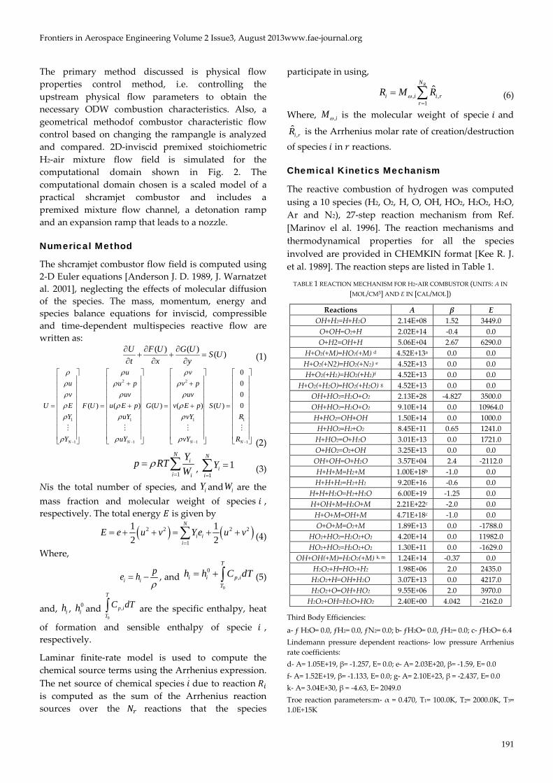
The reactive combustion of hydrogen was computed using a 10 species (H2, O2, H, O, OH, HO2, H2O2, H2O, Ar and N2), 27-step reaction mechanism from Ref. [Marinov el al. 1996]. The reaction mechanisms and thermodynamical properties for all the species involved are provided in CHEMKIN format [Kee R. J. et al. 1989]. The reaction steps are listed in Table 1.
TABLE 1 REACTION MECHANISM FOR H2-AIR COMBUSTOR (UNITS: A IN [MOL/CM3] AND E IN [CAL/MOL])
Reactions A β E OH+H2=H+H2O 2.14E+08 1.52 3449.0
O+OH=O2+H 2.02E+14 -0.4 0.0 O+H2=OH+H 5.06E+04 2.67 6290.0
H+O2(+M)=HO2(+M) d 4.52E+13a 0.0 0.0 H+O2(+N2)=HO2(+N2) e 4.52E+13 0.0 0.0 H+O2(+H2)=HO2(+H2)f 4.52E+13 0.0 0.0
H+O2(+H2O)=HO2(+H2O) g 4.52E+13 0.0 0.0 OH+HO2=H2O+O2 2.13E+28 -4.827 3500.0 OH+HO2=H2O+O2 9.10E+14 0.0 10964.0 H+HO2=OH+OH 1.50E+14 0.0 1000.0 H+HO2=H2+O2 8.45E+11 0.65 1241.0 H+HO2=O+H2O 3.01E+13 0.0 1721.0 O+HO2=O2+OH 3.25E+13 0.0 0.0 OH+OH=O+H2O 3.57E+04 2.4 -2112.0 H+H+M=H2+M 1.00E+18b -1.0 0.0 H+H+H2=H2+H2 9.20E+16 -0.6 0.0
H+H+H2O=H2+H2O 6.00E+19 -1.25 0.0 H+OH+M=H2O+M 2.21E+22c -2.0 0.0
H+O+M=OH+M 4.71E+18c -1.0 0.0 O+O+M=O2+M 1.89E+13 0.0 -1788.0
HO2+HO2=H2O2+O2 4.20E+14 0.0 11982.0 HO2+HO2=H2O2+O2 1.30E+11 0.0 -1629.0
OH+OH(+M)=H2O2(+M) k, m 1.24E+14 -0.37 0.0 H2O2+H=HO2+H2 1.98E+06 2.0 2435.0 H2O2+H=OH+H2O 3.07E+13 0.0 4217.0 H2O2+O=OH+HO2 9.55E+06 2.0 3970.0
H2O2+OH=H2O+HO2 2.40E+00 4.042 -2162.0
Third Body Efficiencies:
a- ƒ H2O= 0.0, ƒH2= 0.0, ƒN2= 0.0; b- ƒH2O= 0.0, ƒH2= 0.0; c- ƒH2O= 6.4 Lindemann pressure dependent reactions- low pressure Arrhenius rate coefficients: d- A= 1.05E+19, β= -1.257, E= 0.0; e- A= 2.03E+20, β= -1.59, E= 0.0 f- A= 1.52E+19, β= -1.133, E= 0.0; g- A= 2.10E+23, β = -2.437, E= 0.0 k- A= 3.04E+30, β = -4.63, E= 2049.0 Troe reaction parameters:m- α = 0.470, T1= 100.0K, T2= 2000.0K, T3= 1.0E+15K
191

www.fae-journal.org Frontiers in Aerospace Engineering Volume 2 Issue 3, August 2013
Solution Method
The computation model for a detonation combustion chamber is a small scale model with skewed inflow configuration, which is the actual configuration for a real-life shcramjet combustion chamber. This is in contrast to a parallel inflow configuration that is widely used in the study of oblique detonation waves for computational advantages. The solution of the partial differential equations was carried out using upwind finite volume procedure. The algorithm used for flux discretization is Liou’s AUSM [Liou et al. 1993] flux vector splitting scheme with vanLeer’s normal second order MUSCL extrapolation for primitive variables [vanLeer B. 1979].
FIG. 2 SCHEMATICS OF THE COMPUTATIONAL DOMAIN
CONSIDERED IN THIS STUDY
The computational domain (Fig. 2) consists of a 20mm×10mm combustor with a ramp of 11mm horizontal span and 20° inclination. The ramp starts at 5mm from the combustor inlet, and is followed by a 4mm and -20° expansion ramp. The basic combustor model is referenced from Ref. [Fort J. A. 1993] one-fifth scale study of induction length and Damköhler number effects. ODW formed for a stoichiometric mixture flow at Mach 5, T= 800K and p= 101kPacondition is shown in Fig. 3, where the simulation is carried out only for the ramp region of the computational domain with a 129*121 grid. The combustion waveis initiated at 4.68mm from the ramp tip along the ramp length, and ends at 9.3mm. The angle of the curved ODW is difficult to measurein Fig. 3; however, the unrelaxed ODW angle of the lower ODW branch for a result presented in the later part of this study (Fig. 6(a))is 38.66°, which isclose to the value of 38.1° obtained fromR-H analysis.
Effects of Mixture Temperature and Pressureon Induction Length
For temperatures lower than 800K, the induction region in Fig. 3 extends along the ramp and eventually grows beyond the ramp length. For ashcramjet
combustor with fixed ramp length, it must be ensured that the induction of an ODW at any operating condition within the flight envelope must not extend beyond the given ramp length. The primary parameters that control the value of induction length at any given Mach number and ramp inclination angle are the mixture temperature and pressure.
FIG. 3 TEMPERARURE AND H2O FLOW CONTOURS FOR M=5,
T=800K AND P=101KPA AT 20° RAMP ANGLE
Higher temperatures can allow for ODWs to form at lower Mach numbers while at higher Mach numbers ODW can be stabilized at much lower temperatures. However, a very low temperature value can result in failure to form the ODW over a fixed ramp length due to large induction lengths. Fig. 4(a) shows the ODW formation at Mach 6, 625 K and 101 kPa with a ramp angle of 20°. The induction length in this case is larger compared to the case with Mach 5 and 800K even though the flow is at a higher Mach number and the effect of a lower flow temperature on induction length is evident.
Upstream mixture flow pressure has a similar effect on the detonation ignition distance, which is seen in Fig. 4(b) at p =125kPa. The increase in pressure has moved the ignition region upstream resulting in a shorter induction length. However, it must be noted that increase in flow pressure does not affect the reaction rate like temperature does, and thus the larger production of H2O in Fig. 4(b) is solely due to a larger distance available along the ramp for combustion of remaining fractions of the reacting species to take place. On the other hand, decreasing the pressure of the upstream flow has the effect of increasing the
192

Frontiers in Aerospace Engineering Volume 2 Issue3, August 2013www.fae-journal.org
induction length as compared in Fig. 5 (a) & (b) for Mach 7 and T= 625Kat pressure conditions of 101 kPa and 85 kPa, respectively.
It is important to note for the results presented in later part of this presentation that while an increase in flow temperature can affect the induction length as well as the ODW angle due to higher amount of heat release caused by increased rate of reaction, pressure changes only appear to affect the induction length.
Induction length values, measured from induction initiation to end along the ramp, for the cases in Fig. 3 & 4 are summarized in Table 2.
TABLE 2 INDUCTION LENGTHS: FROM INDUCTION INITIATION TO END, MEASURED ALONG THE RAMP
Case Induction Length M= 6, T= 625 K, P= 101 kPa 4.9 mm to 9.9 mm M= 6, T= 625 K, P= 125 kPa 3.86 mm to 7.6 mm M= 7, T= 625 K, P= 101 kPa 2.3 mm to 5.14 mm M= 7, T= 625 K, P= 85 kPa 2.97 mm to 6.8 mm
(a) (b)
FIG. 4TEMPERATURE AND H2O CONTOURS FOR (a) M= 6, T= 625K, P= 101KPA (b) M= 6, T= 625K, P= 125KPA AT 20° RAMP ANGLE
(a) (b)
FIG. 5TEMPERATURE AND H2O CONTOURS FOR (a)M= 7, T= 625K, P= 101KPA(b) M=7, T=625K, P= 85KPAAT 20° RAMP ANGLE
193

www.fae-journal.org Frontiers in Aerospace Engineering Volume 2 Issue 3, August 2013
Species Concentration Effects on Induction Length
The effects of equivalence ratio, φ, defined as the ratio of mixture fuel-to-oxidizer mass fractions ratio to stoichiometric fuel-to-oxidizer mass fractions ratio, was analyzed but no significant effect on the induction length was found. However, it does affect the ODW angle, a characteristic which is analyzed in the following section for combustor characteristic control. Thus, at a given Mach number, temperature and pressure condition, with a combustor of a fixed ramp angle and length, the induction length criterion for the formation of ODW over a given ramp length do not show a strong dependency on the fuel concentration of the upstream flow. In fact, for a given flow condition and ramp angle, induction length of OSW-ODW transition is found to be controlled solely by the chemical induction time corresponding to the thermodynamic state of the gases behind the initial OSW.
Combustor Outflow Characteristics
The combustion chamber flow domain shown in Fig. 2 includes a ramp followed by an expansion ramp that leads to the nozzle. A detonation combustor design must ensure that the entire incoming fuel-air mixture flow passes through the ODW for complete combustion. For fixed geometry combustor, at operating conditions different from the design condition the ODW either touches the upper wall surface upstream of the combustor exit or the ODW angle is too low to touch the upper wall surface at all. The latter condition results in low combustion efficiency since a part of the fuel-air mixture spills into the nozzle without passing through the combusting ODW.
The earlier case of the combustor characteristics, i.e. when an ODW touches the combustor upper wall upstream of the combustor exit section, is also detrimental to the shcramjet performance since it leads to friction losses due to reflected ODW at combustor upper wall surface, a local extremely high temperature region, and wall-boundary layer separation due to the shock wave-boundary layer interaction.
In Fig. 6, ODW characteristics for a fixed geometry combustor are shown at increasing Mach numbers under a constant pressure of 101kPa, and temperatures of 800K for Mach 5 and 625K for Mach 6 and 7. The simulations were carried out with a 164*121 grid. At Mach 5 (Fig. 6(a)) the combustor length is sufficient for
the ODW to touch the upper wall just before the combustor exit hence the entire incoming fuel-air mixture burns through the ODW. The ODW has relaxed to a new, lower inclination angle of 37.56°, from the initial ensuing ODW angle of 38.66° of initial ODW branch due to interaction with expansion waves emanating at ramp-summit. Also in Fig. 6(b), at Mach 6, though the ODW does not touch the upper wall, the ODW angle is enough to allow the entire incoming flow to pass through it with negligible spillage (as shown quantitatively in Fig. 7). However, for the case of Mach 7 shown in Fig. 6(c), the ODW angle is too small to burn the entire incoming mixture because of a large spillage gap. Spillage for the three casesis compared quantitatively in Fig. 7, where at Mach 7it is quitesignificant to have a detrimental effect on the combustor efficiency.
FIG. 6COMBUSTOR FLOW FIELD TEMPERATURE CONTOURS
FOR (a) M= 5, T= 800K, P= 101KPA (b) M=6, T=625 K, P=101KPA (c) M=7, T=625K, P=101KPA;THE FINAL, RELAXED, ODW ANGLES
ARE 37.56°, 35.97°, AND 32.4°, RESPECTIVELY
At varying flow conditions for fixed combustor geometry, a mechanism is required to ensure that either the spillage gap is at least reduced to a minimum or that the ODW does not touch the upper wall surface too early. Two types of flow control mechanisms are discussed below: a physical flow
(a)
(b)
(c)
194

Frontiers in Aerospace Engineering Volume 2 Issue3, August 2013www.fae-journal.org
properties control method that ensures the required downstream conditions by controlling the upstream flow properties, and a combustor geometry control method that utilizes varying combustor geometry to ensure optimum downstream condition. The latter method is widely discussed in literatures as a possible mechanism to control the shcramjet combustor characteristics, e.g. by changing the ramp inclination angle for higher combustion efficiency and less spillage. The first method is theoretically well known but is not yet widely studied in shcramjet stability and performance analyses. This study makes an attempt to analyze both the flow control methods and explain how they can be employed in a shcramjet combustor design. However, primary focus is made on the understanding of the working principles of physical flow properties control method, and to analyze its merits.
FIG. 7 H2CONCENTRATIONS AT COMBUSTOR OUTLET
PROVIDING QUATITATIVE ESTIMATIONS FOR SPILLAGE
Combustor Flow Control by Varying the UpstreamFlowProperties
The combustor case in Fig. 6(c) suffers from large spillage due to low ODW angle at Mach 7. R-H analysis shows that at higher Mach numbers ODWs can be stabilized at lower temperatures. As shown in Fig. 9, at any Mach number, decreasing the upstream mixture flow temperature results in shifting of the stability map upwards hence allowing for wider regions to exist at lower levels, e.g. larger variation of equivalence ratio, φ. More importantly, it results in the increase in the ODW angle, β. Fig. 8(a) shows the flow field for Mach 7 by lowering the temperature to 555K from 625K in Fig. 6(c). It can be clearly seen that the ODW angle has changed significantly (with an
increment of 2.28°), and the spillage is reduced as compared quantitatively in Fig. 10.
FIG. 8COMBUSTOR FLOW FIELD TEMPERATURE CONTOURS
AT (a) M= 7, T= 555K, P=101KPA (b) M= 7, T= 555K, P=101KPA, φ=1.2 (c) M= 7, T= 555K, P=125KPA; THE ODW ANGLES HAVE
RELAXED TO 34.68°, 35.1° AND 33.51°, RESPECTIVELY
However, this spillage might still be substantial to effect the combustor performance hence a further attempt to reduce it is carried out in Fig. 8(b) by increasing the upstream mixture equivalence ratio by 0.2. R-H analysis indicates that increasing equivalence ratios might also have the effect of increasing the ODW angle as schematically shown in Fig. 9. But this is only possible if there is an unburned fraction of O2 to react with an excess amount of H2 fuel. As seen in Fig. 8(b), the change in ODW inclination angle is small (increment by 0.42°) and from Figure 10 the spillage is not seen to get much better than the earlier case. Similar to the case for induction length, equivalence ratio changes seem to have very small effects to be of much significance since the concentration of O2 is insufficient for further reaction and heat release. In fact, the lack of performance improvement at the expenditure of extra fuel can become negative to the combustor overall performance. This is especially evident in Fig. 10 where the fraction of unburned H2 concentration in the combustion region is very large compared to the other cases that correspond to
0.000
0.002
0.004
0.006
0.008
0.010
0 0.005 0.01 0.015 0.02 0.025 0.03
Com
bust
or H
eigh
t
YH2
M= 5, T= 800 KM= 6, T= 625 KM= 7, T= 625 K
(a)
(b)
(c)
195

www.fae-journal.org Frontiers in Aerospace Engineering Volume 2 Issue 3, August 2013
mixtures with stoichiometric H2-air ratios. Hence, it can be concluded that varying the equivalence ratio above 1 can have negative effects on the performance from the present perspective.
FIG. 9 TEMPERATURE AND EQUIVALENCE RATIO EFFECTS BASED ON PHYSICAL FLOW PROPERTIES CONTROL (R-H
INTERPRETATION)
FIG. 10H2 CONCENTRATIONS AT COMBUSTOR OUTLET
PROVIDING QUATITATIVE ESTIMATIONS FOR SPILLAGE
Combustor Flow Control by Varying theCombustor Geometry
To change the ODW characteristics mechanically, (a) ramp angle was increased to 21.5° at Mach 7, 625K and 101 kPa and the modified combustor flow field was computed, and (b) the combustor flow field was computed at Mach 7, 555K and 101 kPa for a modified ramp angle of 20.5°. The flow field temperatures are shown in Fig. 11. From Fig. 12 it can be seen that the spillage in case (a) is more than in case (b) despite the higher ramp angle. In fact, the spillage in case (b) is the least of all the Mach 7 cases considered above.
FIG. 11COMBUSTOR FLOW FIELD TEMPERATURE CONTOURS FOR (a) M= 7, T= 625K AND P= 101KPA AT RAMP ANGLE θ=21.5° (b) M= 7, T= 555K AND P= 101KPA AT RAMP ANGLE θ=20.5°; THE
ODW ANGLES HAVE RELAX TO THE VALUES OF 32.79° AND 35.55°, RESPECTIVELY
FIG. 12 H2 CONCENTRATIONS AT COMBUSTOR OUTLET
PROVIDING QUATITATIVE ESTIMATIONS FOR SPILLAGE
This could imply that perhaps a coupled flow control method combiningthe control of physical flow properties and variable combustor geometry might be the most beneficial. This conclusion can be backed by the fact that, since ODWs at higher wedge angles suffer from higher shock and friction losses, it would be desirable to avoid making large increments in ramp angles and less frequently. Instead, the control mechanism can rely on simply changing physical flow properties within a limited range of Mach numbers, while at increased Mach numbers, where spillage become significant or when adjustments in induction length is required, relying on occasional small increments in ramp angle to avoid losses. For example,
0.000
0.002
0.004
0.006
0.008
0.010
0 0.005 0.01 0.015 0.02 0.025 0.03
Com
bust
or H
eigh
t
YH2
M= 7, T= 555 KM= 7, T= 555 K, φ= 1.2 M= 7, T= 555 K, p= 125 kPa
0.000
0.002
0.004
0.006
0.008
0.010
0 0.005 0.01 0.015 0.02 0.025 0.03
Com
bust
or H
eigh
t
YH2
M= 7, T=625 KM= 7, T= 625 K, θ= 21.5° M= 7, T= 555 K, θ= 20.5°
(a)
(b)
196

Frontiers in Aerospace Engineering Volume 2 Issue3, August 2013www.fae-journal.org
between Mach numbers 5 and 6 as considered here adjustments in physical flow propertiesare sufficient to ensure good combustor performance. At Mach numbers above 6, flow properties control of temperature and pressure are still sufficient to achieve necessary combustor characteristics until the Mach number approaches 7. At Mach numbers close to Mach 7, slight change in ramp angle, combined with adjustments in physical flow properties if necessary, is seen to providemore suitableupstream mixture flow condition for good combustor performance.
Conclusion
A combustor flow field characteristic for a shcramjet was studied for induction length and combustor outflow control, by controlling physical flow properties of the upstream mixture. Also, control of spillage amount at the combustor outlet was studied by changing the combustor ramp angle. Changing the mixture temperature provided good control over the ODW induction length as well as the inclination angle. Decreasing the mixture temperature and pressure resulted in increasing induction length, while increasing fuel concentrations above stoichiometric proportions had no significant effect on ODW characteristics but can rather have negative effects on combustor performance. Decrease in mixture temperature also resulted in an increase in ODW angle which in turn helps to reduce spillage amount.
For larger combustion chamber sizes, the wedge length is large enough to hold ODWs at lower pressures (typically between 10-40 kPa) that correspond to the conditions of high-altitude flights. Therefore, varying the ramp angle to obtain suitable combustor outflow characteristics is possible, and a very small change in the inclination angle can have relatively larger change in the ODW characteristics. Mixture pressure and temperature are more readily controlled by controlling fuel injection characteristics, inlet conditions, etc., in contrast to changing the ramp angle. Hence, control of physical flow properties has an important merit of simplicity compared to the method of control of combustor geometry and can be more readily utilized in a shcramjet combustor design. It is possible to avoid large increments in ramp angles for geometrical control of shcramjet combustor by relying for most part on control of flow properties techniques for narrow Mach number ranges. A coupled flow control method, combining the control of physical flow properties and combustor geometry might be the most beneficial for operations at a wide
range of Mach numbers.
REFERENCES
Alexander, D. C. and Sislian, J. P. “A Computational Study
of the Propulsive Characteristics of a Shcramjet Engine”,
Journal of Propulsion and Power, Vol. 24, No. 1, 34–44,
2008.
Alexander, D. C., Sislian, J. P. and Parent, B. “Hypervelocity
Fuel/Air Mixing in Mixed-Compression Inlets of
Shcramjets”, AIAA Journal, Vol. 44, No. 10, 2145–2155,
2006.
Anderson, John D. Jr. Hypersonic and High Temperature
Gas Dynamics. McGraw-Hill Book Company, 1989.
Chan Jonathan. “Numerically Simulated Comparative
Performance of a Scramjet and Shcramjet at Mach 11.”
MSc. Thesis, Graduate Department of Aerospace Science
and Engineering, University of Toronto, 2010.
Choi, J. Y., Edward, J. R. and Shin, In-Seuck J. “Unstable
combustion induced by oblique shock waves at non-
attaching condition of the oblique detonation wave”,
Proceedings of the Combustion Institute, Vol. 32, 2387–
2396, 2009.
Dabora, E. K., Desbordes, D., Guerraud, C. and Wagner, H.
G. “Oblique Detonations at Hypersonic Velocities”,
Progress in Astronautics and Aeronautics, Vol. 133, 187-
204, 1991.
Desbordes, D., Hamada, L. and Guerraud, C. “Supersonic
H2-air combustion behind oblique shock waves”, Shock
Waves 4, 339-345, 1995.
Dudebout, R., Sislian, J. P. and Oppitz, R. “Numerical
Simulation of Hypersonic Shock-Induced Combustion
Ramjets”, Journal of Propulsion and Power, Vol. 14, No. 6,
869–879, 1998.
Dunlap, R., Brehm, R. L. and Nicholls, J. A. "A Preliminary
Study of the Application of Steady-State Detonative
Combustion to a Reaction Engine", Jet Propulsion, Vol. 28,
No. 7, 451-456, 1958.
Figueira da Silva, L. Fernando. and Deshailes, Bruno
“Stabilization of an Oblique Detonation Wave by a
Wedge: A Parametric Numerical Study”, Combustion
and Flame, Vol. 121, 152–166, 2000.
Fort, James A. “A Numerical Study of Attached Oblique
Detonation.” PhD diss., University of Washington, 1993.
Fusina, G. “Numerical Investigation of Oblique Detonation
197

www.fae-journal.org Frontiers in Aerospace Engineering Volume 2 Issue 3, August 2013
Waves for a Shcramjet Combustor.” PhD diss., Graduate
School of Aerospace Science and Engineering, University
of Toronto, 2003.
Hertzberg, A., Bruckner, A. P. and Bogdanoff, D. W. “Ram
Accelerator: A New Chemical Methods for Accelerating
Projectiles to Ultrahigh Velocities”, AIAA Journal 26(2),
195-203, 1988.
Kee, R.J., Rupley, F.M. and Miller, J.A., "Chemkin-II: A
Fortran Chemical Kinetics Package for the Analysis of
Gas-Phase Chemical Kinetics", Sandia Report SAND89-
8009.UC-401, September 1989.
http://www2.galcit.caltech.edu/EDL/public/formats/chem
kin.html.
Lehr, H. F. “Experiments on Shock-Induced Combustion”,
Astronautics Acta., Vol. 17, No.4-5, 589-597, 1972.
Liou, M.S. and Steffen, C. J. Jr., “A new flux splitting
scheme”, Computational Physics, Vol. 107, No. 1, 23-39,
1993.
Marinov, N., Westbrook, C.K. and Pitz, W.J., "Detailed and
Global Chemical Kinetics Model for Hydrogen",
Transport Phenomena in Combustion, Volume 1, edited
by S. H. Chan, Talyor and Francis, Washington, DC, 1996.
Nicholls, J. A., Dabora, E. K. and Gealer, R. L. "Studies in
Connection with Stabilized Detonation Wave", 7th
Symposium(International) on Combustion, Butterworths,
London, 755-772, 1959.
Pimentel, C. A. R., Azevedo, J. L. F., Figueira da Silva, L.F.
and Deshaies, B. “Numerical Study of Wedge Supported
Oblique Shock Wave-Oblique Detonation Wave
Transitions”, Journal of the Brazilian Society of
Mechanical Sciences, Vol. XXIV, 149-157, 2002.
Pratt, David T., Humphrey Joseph W. and Glenn, Dennis E.
“Morphology of Standing Oblique Detonation Waves”,
Journal of Propulsion, Vol. 7, No. 5, 837-845, 1991.
Sislian, J. P. and Parent, B. “Hypervelocity Fuel/Air Mixing
in a Shcramjet Inlet”, Journal of Propulsion and Power,
Vol. 20, No. 2, 263-272, 2004.
van Leer, B. “Towards the ultimate conservative difference
scheme V- A second-order sequel to Godunov method”,
Journal of Computational Physics, Vol. 32, No. 1, 101–136,
1979.
Warnatz, J., et al., Combustion: Physcial and Chemical
Fundamentals and Simulation, Experiments, Pollutants
Formation, 3rd Edition, Berlin, Heidelberg, New York:
Springer-Verlag, 2001.
Yungster, S. and Bruckner,A. P. “Computational Studies of a
Superdetonative Ram Accelerator Mode”,Journal of
Propulsion, Vol. 8, No. 2, 457-463, 1992.
198