numerical study on load distribution in hc floors
TRANSCRIPT

Aix-en-Provence, May 29 - June 1
NUMERICAL STUDY ON LOAD NUMERICAL STUDY ON LOAD DISTRIBUTION IN HC FLOORSDISTRIBUTION IN HC FLOORS
P. Bernardi, R. Cerioni, N. Garutti & E. Michelini
DISTRIBUTION IN HC FLOORSDISTRIBUTION IN HC FLOORS
Dept. of Civil and Environmental Engineering and Architecture, University of Parma, Parma, Italy

, E
. M
ich
eli
ni
inH
Cfl
oo
rs”
LOAD DISTRIBUTION IN HC FLOORSLOAD DISTRIBUTION IN HC FLOORS
REQUIREMENTS OF
HC FLOORS• Vertical load bearing capacity
• Transverse load distribution � longitudinal joints
Load
INTRODUCTION NLFE ANALYSES NUMERICAL RESULTS CONCLUSIONS
Be
rna
rdi,
R. C
eri
on
i, N
. G
aru
tti,
E. M
ich
eli
ni
“N
um
eri
ca
l s
tud
yo
nlo
ad
dis
trib
uti
on
in
MAIN EFFECTS DUE TO CONCENTRATED LOADS:
• additional shear stresses due to torsion
• transverse bending moments � two-way slab behavior of the floor
Load
1/17
P. B
ern
ard
i“N
um
eri
ca
l s
tud
y
• transverse bending moments � two-way slab behavior of the floor
Transverse distribution of shear forces and of bending and torsional moments:
- SIMPLIFIED CURVES (DESIGN STANDARDS)
- NUMERICAL APPROACHES

, E
. M
ich
eli
ni
inH
Cfl
oo
rs”
SIMPLIFIED CURVES (UNI EN 1168)SIMPLIFIED CURVES (UNI EN 1168)
Main simplified assumptions:
• Theory of elasticity
• Simply supported floor
INTRODUCTION NLFE ANALYSES NUMERICAL RESULTS CONCLUSIONS
Be
rna
rdi,
R. C
eri
on
i, N
. G
aru
tti,
E. M
ich
eli
ni
“N
um
eri
ca
l s
tud
yo
nlo
ad
dis
trib
uti
on
in
� Not clear if they are referred to:
• bending moment distribution at midspan
• Simply supported floor
• Five 1200mm wide units
• Line or point loads applied in the
centre or along the edge of the floor
MAY BE VERY
2/17
P. B
ern
ard
i“N
um
eri
ca
l s
tud
y
• bending moment distribution at midspan
• shear force distribution at supports
MAY BE VERY
DIFFERENT FROM
EACH OTHERS
� Not dependent on the ratio EI/GJt of the HC cross section
NUMERICAL APPROACHES required
, E
. M
ich
eli
ni
inH
Cfl
oo
rs”
SIMPLIFIED LINEAR ELASTIC FE MODELSSIMPLIFIED LINEAR ELASTIC FE MODELS
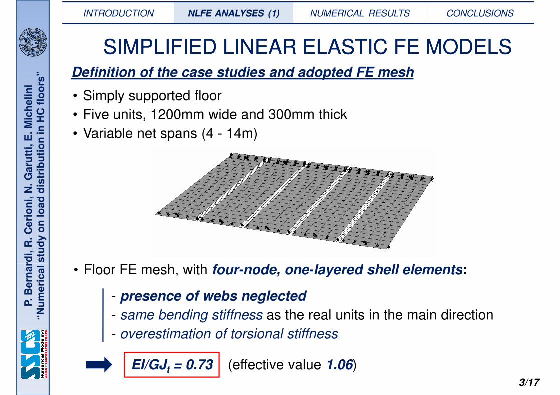
• Simply supported floor
• Five units, 1200mm wide and 300mm thick
• Variable net spans (4 - 14m)
Definition of the case studies and adopted FE mesh
INTRODUCTION NLFE ANALYSES (1) NUMERICAL RESULTS CONCLUSIONS
Be
rna
rdi,
R. C
eri
on
i, N
. G
aru
tti,
E. M
ich
eli
ni
“N
um
eri
ca
l s
tud
yo
nlo
ad
dis
trib
uti
on
in • Variable net spans (4 - 14m)
• Floor FE mesh, with four-node, one-layered shell elements:
3/17
P. B
ern
ard
i“N
um
eri
ca
l s
tud
y
• Floor FE mesh, with four-node, one-layered shell elements:
- presence of webs neglected
- same bending stiffness as the real units in the main direction
- overestimation of torsional stiffness
EI/GJt = 0.73 (effective value 1.06)
, E
. M
ich
eli
ni
inH
Cfl
oo
rs”
SIMPLIFIED LINEAR ELASTIC FE MODELSSIMPLIFIED LINEAR ELASTIC FE MODELS
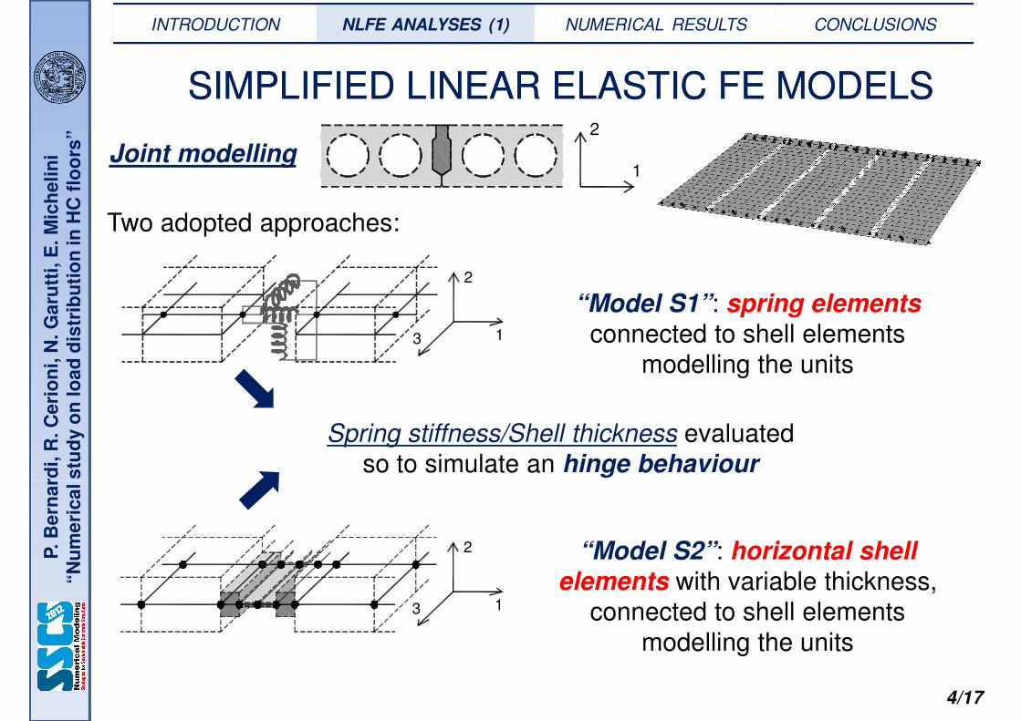
Joint modelling
Two adopted approaches:
1
2
INTRODUCTION NLFE ANALYSES (1) NUMERICAL RESULTS CONCLUSIONS
Be
rna
rdi,
R. C
eri
on
i, N
. G
aru
tti,
E. M
ich
eli
ni
“N
um
eri
ca
l s
tud
yo
nlo
ad
dis
trib
uti
on
in
“Model S1”: spring elements
connected to shell elements
modelling the units
Spring stiffness/Shell thickness evaluated
so to simulate an hinge behaviour
1
2
3
4/17
P. B
ern
ard
i“N
um
eri
ca
l s
tud
y
“Model S2”: horizontal shell
elements with variable thickness,
connected to shell elements
modelling the units
1
2
3

, E
. M
ich
eli
ni
inH
Cfl
oo
rs”
SIMPLIFIED FE MODELS: NUMERICAL RESULTSSIMPLIFIED FE MODELS: NUMERICAL RESULTS
Bending moment,
slab j: βj·qL2/8
Load on slab j:
αj·qL
-]
theoretical [9]
EI/GJt = 0.73line load on panel 3
INTRODUCTION NLFE ANALYSES NUMERICAL RESULTS (1) CONCLUSIONS
Be
rna
rdi,
R. C
eri
on
i, N
. G
aru
tti,
E. M
ich
eli
ni
“N
um
eri
ca
l s
tud
yo
nlo
ad
dis
trib
uti
on
in
0.00
0.10
0.20
0.30
0.40
0.50
lenght [m]
ββββ1 ≡ ββββ5
ββββ2 ≡ ββββ4
ββββ3
fra
ctio
n o
f b
end
ing
mo
men
t [
-
UNI EN 1168theoretical [9]numerical, S1 model
numerical, S2 model
0.00
0.10
0.20
0.30
0.40
0.50
lenght [m]
αααα1 ≡ αααα5
αααα2 ≡ αααα4
αααα3
fra
ctio
n o
f to
tal lo
ad
[ -
]
theoretical [9]numerical, S1 modelnumerical, S2 model
([9] Lindström 2010) ([9] Lindström 2010)
5/17
P. B
ern
ard
i“N
um
eri
ca
l s
tud
y
0.00
2 4 6 8 10 12 14
0.00
2 4 6 8 10 12 14a) b)
• Shear at support less distributed with respect to bending effects.
• Similar numerical curves (S1, S2).
Better agreement with theoretical provisions in terms of bending effects.
bending moment at midspan total load at support
, E
. M
ich
eli
ni
inH
Cfl
oo
rs”
Bending moment,
slab j: βj·qL2/8
Load on slab j:
αj·qL
0.50
0.60
0.70
ββββ1
fract
ion
of
ben
din
g m
om
ent
[ -
]
theoretical [9]numerical, S1 modelnumerical, S2 model
0.50
0.60
0.70
αααα1
fract
ion
of
tota
l lo
ad
[ -
]
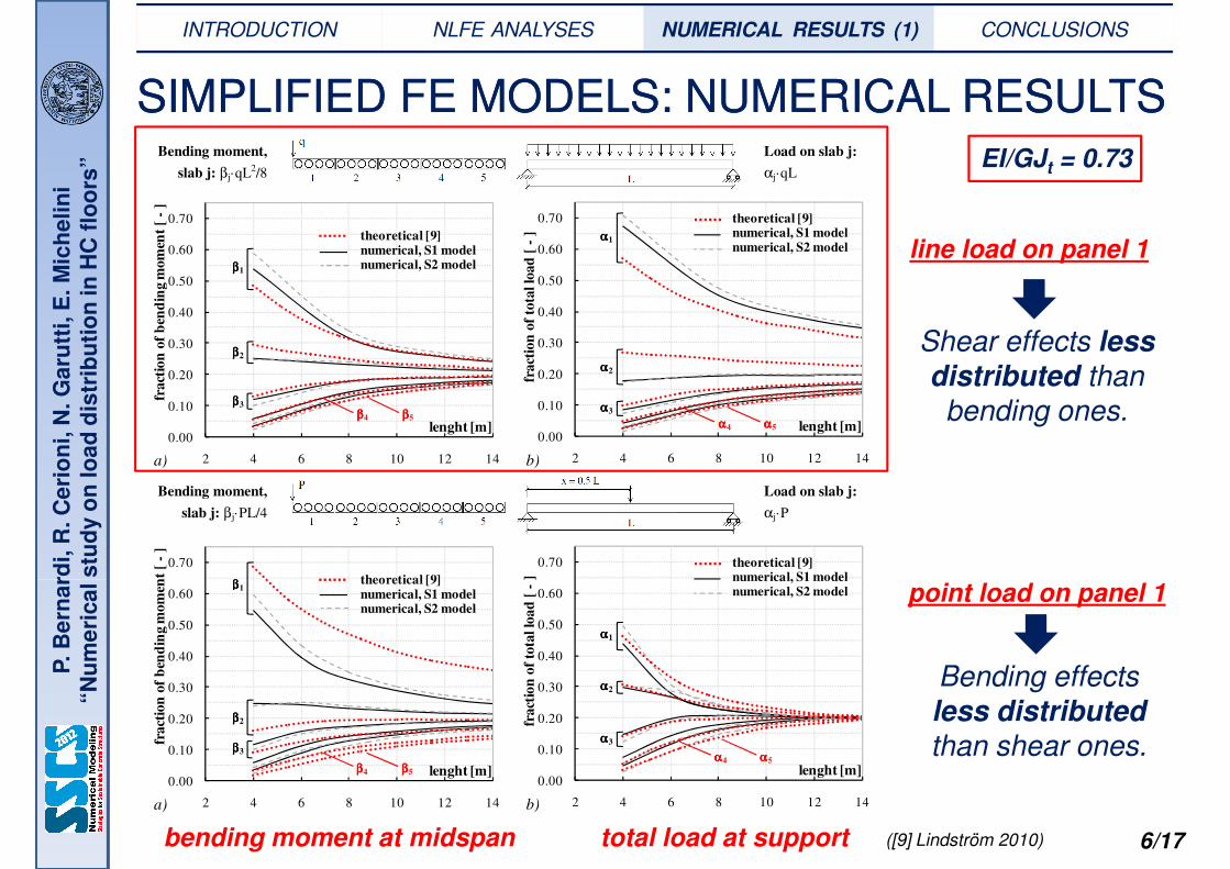
theoretical [9]numerical, S1 modelnumerical, S2 model line load on panel 1
SIMPLIFIED FE MODELS: NUMERICAL RESULTSSIMPLIFIED FE MODELS: NUMERICAL RESULTS
EI/GJt = 0.73
INTRODUCTION NLFE ANALYSES NUMERICAL RESULTS (1) CONCLUSIONS
Be
rna
rdi,
R. C
eri
on
i, N
. G
aru
tti,
E. M
ich
eli
ni
“N
um
eri
ca
l s
tud
yo
nlo
ad
dis
trib
uti
on
in
Bending moment,
slab j: βj·PL/4
Load on slab j:
αj·P
0.70
ββββ
fract
ion
of
ben
din
g m
om
ent
[ -
]
theoretical [9]
0.70
]
theoretical [9]numerical, S1 model
0.00
0.10
0.20
0.30
0.40
2 4 6 8 10 12 14
lenght [m]
fract
ion
of
ben
din
g m
om
ent
[
ββββ2
ββββ3
ββββ4 ββββ5
0.00
0.10
0.20
0.30
0.40
2 4 6 8 10 12 14
lenght [m]
fract
ion
of
tota
l lo
ad
[
αααα2
αααα3
αααα4 αααα5
a) b)
point load on panel 1
Shear effects less distributed than
bending ones.
6/17
P. B
ern
ard
i“N
um
eri
ca
l s
tud
y
0.00
0.10
0.20
0.30
0.40
0.50
0.60
2 4 6 8 10 12 14
lenght [m]
ββββ1
fract
ion
of
ben
din
g m
om
ent
[
theoretical [9]numerical, S1 modelnumerical, S2 model
ββββ2
ββββ3
ββββ4 ββββ5
0.00
0.10
0.20
0.30
0.40
0.50
0.60
2 4 6 8 10 12 14
lenght [m]
αααα1
fract
ion
of
tota
l lo
ad
[ -
] numerical, S1 modelnumerical, S2 model
αααα2
αααα3
αααα4 αααα5
a) b)
point load on panel 1
Bending effects
less distributed than shear ones.
([9] Lindström 2010)bending moment at midspan total load at support

, E
. M
ich
eli
ni
inH
Cfl
oo
rs”
Bending moment,
slab j: βj·qL2/8
Load on slab j:
αj·qL
0.50
0.60
0.70
ββββ1
fract
ion
of
ben
din
g m
om
ent
[ -
]
theoretical [9]numerical, S1 modelnumerical, S2 model
0.50
0.60
0.70
αααα1
fract
ion
of
tota
l lo
ad
[ -
]
theoretical [9]numerical, S1 modelnumerical, S2 model line load on panel 1
SIMPLIFIED FE MODELS: NUMERICAL RESULTSSIMPLIFIED FE MODELS: NUMERICAL RESULTS
EI/GJt = 0.73
INTRODUCTION NLFE ANALYSES NUMERICAL RESULTS (1) CONCLUSIONS
Be
rna
rdi,
R. C
eri
on
i, N
. G
aru
tti,
E. M
ich
eli
ni
“N
um
eri
ca
l s
tud
yo
nlo
ad
dis
trib
uti
on
in
Bending moment,
slab j: βj·PL/4
Load on slab j:
αj·P
0.70
ββββ
fract
ion
of
ben
din
g m
om
ent
[ -
]
theoretical [9]
0.70
]
theoretical [9]numerical, S1 model
0.00
0.10
0.20
0.30
0.40
2 4 6 8 10 12 14
lenght [m]
fract
ion
of
ben
din
g m
om
ent
[
ββββ2
ββββ3
ββββ4 ββββ5
0.00
0.10
0.20
0.30
0.40
2 4 6 8 10 12 14
lenght [m]
fract
ion
of
tota
l lo
ad
[
αααα2
αααα3
αααα4 αααα5
a) b)
point load on panel 1
Shear effects less distributed than
bending ones.
6/17
P. B
ern
ard
i“N
um
eri
ca
l s
tud
y
0.00
0.10
0.20
0.30
0.40
0.50
0.60
2 4 6 8 10 12 14
lenght [m]
ββββ1
fract
ion
of
ben
din
g m
om
ent
[
theoretical [9]numerical, S1 modelnumerical, S2 model
ββββ2
ββββ3
ββββ4 ββββ5
0.00
0.10
0.20
0.30
0.40
0.50
0.60
2 4 6 8 10 12 14
lenght [m]
αααα1
fract
ion
of
tota
l lo
ad
[ -
] numerical, S1 modelnumerical, S2 model
αααα2
αααα3
αααα4 αααα5
a) b)
point load on panel 1
Bending effects
less distributed than shear ones.
([9] Lindström 2010)bending moment at midspan total load at support

, E
. M
ich
eli
ni
inH
Cfl
oo
rs”
MORE COMPLEX FE MODELSMORE COMPLEX FE MODELS
Simplified models not able to represent the effective behaviour of HC floors
For a correct description of shear and torsion transferring mechanisms it is
necessary to model each web with solid or shell elements
INTRODUCTION NLFE ANALYSES (2) NUMERICAL RESULTS CONCLUSIONS
Be
rna
rdi,
R. C
eri
on
i, N
. G
aru
tti,
E. M
ich
eli
ni
“N
um
eri
ca
l s
tud
yo
nlo
ad
dis
trib
uti
on
in necessary to model each web with solid or shell elements
7/17
P. B
ern
ard
i“N
um
eri
ca
l s
tud
y
FE mesh, with four-node, one-layered shell elements representing the middle
plane of the webs and of the bottom and top slabs for HC units
EI/GJt = 1.06 (effective value)

, E
. M
ich
eli
ni
inH
Cfl
oo
rs”
MORE COMPLEX FE MODELSMORE COMPLEX FE MODELS
Joint modelling1
2
INTRODUCTION NLFE ANALYSES (2) NUMERICAL RESULTS CONCLUSIONS
Be
rna
rdi,
R. C
eri
on
i, N
. G
aru
tti,
E. M
ich
eli
ni
“N
um
eri
ca
l s
tud
yo
nlo
ad
dis
trib
uti
on
in
“Model C1”: spring elements
connected to shell elements
nodes, in the external webs of
the units
“Model C2”: horizontal shell
elements connected to shell
element nodes, in the external
same as
“Model S1”
same as
“Model S2”
8/17
P. B
ern
ard
i“N
um
eri
ca
l s
tud
y
element nodes, in the external
webs of the units
“Model C3”: vertical shell
elements connected to shell
element nodes, in the external
webs of the units

, E
. M
ich
eli
ni
inH
Cfl
oo
rs”
COMPARISONS BETWEEN SIMPLIFIED AND COMPARISONS BETWEEN SIMPLIFIED AND COMPLEX MODELSCOMPLEX MODELS
• Same modelling technique for joints but different schematization for units
e.g.:
INTRODUCTION NLFE ANALYSES NUMERICAL RESULTS (2) CONCLUSIONS
Be
rna
rdi,
R. C
eri
on
i, N
. G
aru
tti,
E. M
ich
eli
ni
“N
um
eri
ca
l s
tud
yo
nlo
ad
dis
trib
uti
on
in
Bending moment,
slab j: βj·qL2/8
Load on slab j:
αj·qL
0.70
0.80
0.90
ββββ
fra
ctio
n o
f b
end
ing m
om
ent
[ -
]
numerical, C2 modelnumerical, S2 model
0.70
0.80
0.90
αααα1
numerical, C2 modelnumerical, S2 model
fra
ctio
n o
f to
tal lo
ad
[ -
]
e.g.:
S2
When considering the real floor
geometry
C2
line load on panel 1
9/17
P. B
ern
ard
i“N
um
eri
ca
l s
tud
y
0.00
0.10
0.20
0.30
0.40
0.50
0.60
2 4 6 8 10 12 14
lenght [m]
ββββ1
fra
ctio
n o
f b
end
ing m
om
ent
[
ββββ2
ββββ3
ββββ4 ββββ5
0.00
0.10
0.20
0.30
0.40
0.50
0.60
2 4 6 8 10 12 14
lenght [m]
fra
ctio
n o
f to
tal lo
ad
[
αααα3
αααα2
αααα4 αααα5
a) b)
greater concentration
of loading
effects
bending moment at midspan total load at support
, E
. M
ich
eli
ni
inH
Cfl
oo
rs”
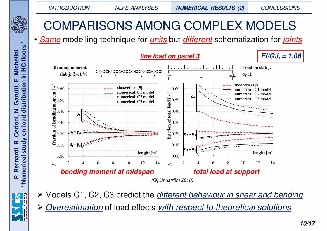
COMPARISONS AMONG COMPLEX MODELSCOMPARISONS AMONG COMPLEX MODELS• Same modelling technique for units but different schematization for joints
Bending moment,
slab j: βj·qL2/8
Load on slab j:
αj·qL
EI/GJt = 1.06line load on panel 3
INTRODUCTION NLFE ANALYSES NUMERICAL RESULTS (2) CONCLUSIONS
Be
rna
rdi,
R. C
eri
on
i, N
. G
aru
tti,
E. M
ich
eli
ni
“N
um
eri
ca
l s
tud
yo
nlo
ad
dis
trib
uti
on
in j
j
0.00
0.10
0.20
0.30
0.40
0.50
0.60
lenght [m]
ββββ1 ≡ ββββ5
ββββ2 ≡ ββββ4
ββββ3
fract
ion
of
ben
din
g m
om
ent
[ -
]
theoretical [9]numerical, C1 modelnumerical, C2 model
numerical, C3 model
0.00
0.10
0.20
0.30
0.40
0.50
0.60
lenght [m]αααα1 ≡ αααα5
αααα2 ≡ αααα4
αααα3
theoretical [9]numerical, C1 modelnumerical, C2 model
numerical, C3 model
fra
ctio
n o
f to
tal lo
ad
[ -
]
10/17
P. B
ern
ard
i“N
um
eri
ca
l s
tud
y
0.00
2 4 6 8 10 12 14
lenght [m]
0.00
2 4 6 8 10 12 14
lenght [m]
a) b)
� Models C1, C2, C3 predict the different behaviour in shear and bending
� Overestimation of load effects with respect to theoretical solutions
bending moment at midspan total load at support([9] Lindström 2010)

, E
. M
ich
eli
ni
inH
Cfl
oo
rs”
� Different
Bending moment,
slab j: βj·qL2/8
Load on slab j:
αj·qL
0.80
0.90
fra
ctio
n o
f b
end
ing
mom
ent
[ -
]
theoretical [9]numerical, C1 modelnumerical, C2 model
0.80
0.90
αααα1
theoretical [9]numerical, C1 model
-]
COMPARISONS AMONG COMPLEX MODELSCOMPARISONS AMONG COMPLEX MODELSline load on panel 1
EI/GJt = 1.06
INTRODUCTION NLFE ANALYSES NUMERICAL RESULTS (2) CONCLUSIONS
Be
rna
rdi,
R. C
eri
on
i, N
. G
aru
tti,
E. M
ich
eli
ni
“N
um
eri
ca
l s
tud
yo
nlo
ad
dis
trib
uti
on
in
Different behaviour in shear and bending
� Overestimation of load effects with respect to theoretical
solutions
especially for shear
0.00
0.10
0.20
0.30
0.40
0.50
0.60
0.70
2 4 6 8 10 12 14
lenght [m]
ββββ1
fra
ctio
n o
f b
end
ing
mom
ent
[
numerical, C2 model
ββββ2
ββββ3
ββββ4 ββββ5
0.00
0.10
0.20
0.30
0.40
0.50
0.60
0.70
2 4 6 8 10 12 14
lenght [m]
αααα1
numerical, C2 model
fra
ctio
n o
f to
tal lo
ad
[ -
αααα2
αααα3
αααα4
αααα5
0.75
0.85
0.95
fra
ctio
n o
f b
end
ing
mom
ent
[ -
]
theoretical [9]numerical, C3 model
0.75
0.85
0.95
αααα1
theoretical [9]numerical, C3 model
fract
ion
of
tota
l lo
ad
[ -
]
a) b)
11/17
P. B
ern
ard
i“N
um
eri
ca
l s
tud
y
especially for shear distribution
-0.05
0.05
0.15
0.25
0.35
0.45
0.55
0.65
0.75
2 4 6 8 10 12 14
lenght [m]
ββββ1
fra
ctio
n o
f b
end
ing
mom
ent
[
ββββ2
ββββ3
ββββ4 ββββ5
-0.05
0.05
0.15
0.25
0.35
0.45
0.55
0.65
0.75
2 4 6 8 10 12 14
lenght [m]
1
fract
ion
of
tota
l lo
ad
[
αααα2
αααα3
αααα4
αααα5
a) b)
bending moment at midspan total load at support ([9] Lindström 2010)

, E
. M
ich
eli
ni
inH
Cfl
oo
rs”
� Different
Bending moment,
slab j: βj·PL/4
Load on slab j:
αj·P
0.60
0.70 ββββ1
fract
ion
of
ben
din
g m
om
ent
[ -
]
theoretical [9]numerical, C1 modelnumerical, C2 model 0.60
0.70
αααα1
theoretical [9]numerical, C1 model
-]
COMPARISONS AMONG COMPLEX MODELSCOMPARISONS AMONG COMPLEX MODELSpoint load on panel 1
EI/GJt = 1.06
INTRODUCTION NLFE ANALYSES NUMERICAL RESULTS (2) CONCLUSIONS
Be
rna
rdi,
R. C
eri
on
i, N
. G
aru
tti,
E. M
ich
eli
ni
“N
um
eri
ca
l s
tud
yo
nlo
ad
dis
trib
uti
on
in
� Different behaviour in shear and bending
� Overestimation of total load with respect to theoretical
solutions
� Greater load effects redistribution
0.00
0.10
0.20
0.30
0.40
0.50
0.60
2 4 6 8 10 12 14
lenght [m]
fract
ion
of
ben
din
g m
om
ent
[
numerical, C2 model
ββββ2
ββββ3
ββββ4 ββββ5
0.00
0.10
0.20
0.30
0.40
0.50
0.60
2 4 6 8 10 12 14
lenght [m]
1
numerical, C2 model
fract
ion
of
tota
l lo
ad
[ -
αααα2
αααα4 αααα5
αααα3
0.65
0.75
0.85
ββββ1
fract
ion
of
ben
din
g m
om
ent
[ -
]
theoretical [9]numerical, C3 model
0.65
0.75
0.85
αααα1
theoretical [9]numerical, C3 model
fract
ion
of
tota
l lo
ad
[ -
]
c) d)
12/17
P. B
ern
ard
i“N
um
eri
ca
l s
tud
y
effects redistribution
in bending with respect to shear, differently from
theoretical solutions
-0.05
0.05
0.15
0.25
0.35
0.45
0.55
0.65
2 4 6 8 10 12 14
lenght [m]
fract
ion
of
ben
din
g m
om
ent
[
ββββ2
ββββ3
ββββ4 ββββ5
-0.05
0.05
0.15
0.25
0.35
0.45
0.55
0.65
2 4 6 8 10 12 14
lenght [m]
1
fract
ion
of
tota
l lo
ad
[
αααα2
αααα3
αααα4
αααα5
c) d)
bending moment at midspan total load at support ([9] Lindström 2010)
, E
. M
ich
eli
ni
inH
Cfl
oo
rs”
FE MODEL VALIDATION FE MODEL VALIDATION –– COMPARISONS COMPARISONS WITH EXPERIMENTAL RESULTSWITH EXPERIMENTAL RESULTS
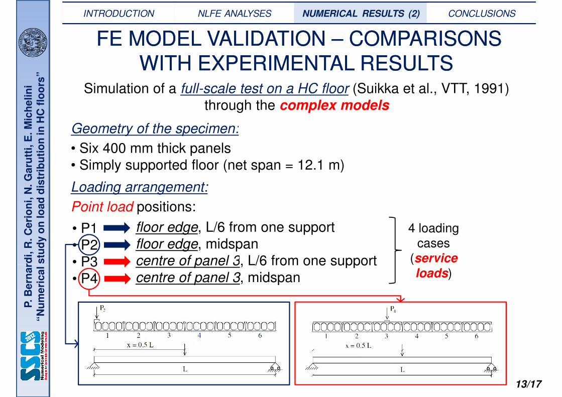
Simulation of a full-scale test on a HC floor (Suikka et al., VTT, 1991)
through the complex models
Geometry of the specimen:
INTRODUCTION NLFE ANALYSES NUMERICAL RESULTS (2) CONCLUSIONS
Be
rna
rdi,
R. C
eri
on
i, N
. G
aru
tti,
E. M
ich
eli
ni
“N
um
eri
ca
l s
tud
yo
nlo
ad
dis
trib
uti
on
in Geometry of the specimen:
• Six 400 mm thick panels
• Simply supported floor (net span = 12.1 m)
Loading arrangement:
Point load positions:
• P1
• P2
• P3
floor edge, L/6 from one support
floor edge, midspan
centre of panel 3, L/6 from one support
4 loading cases
(service
13/17
P. B
ern
ard
i“N
um
eri
ca
l s
tud
y
• P3
• P4
centre of panel 3, L/6 from one support
centre of panel 3, midspan
(service
loads)

, E
. M
ich
eli
ni
inH
Cfl
oo
rs”
Flexural behaviour
Numerical values of
midspan deflections are:
FE MODEL VALIDATION FE MODEL VALIDATION –– COMPARISONS COMPARISONS WITH EXPERIMENTAL RESULTSWITH EXPERIMENTAL RESULTS
INTRODUCTION NLFE ANALYSES NUMERICAL RESULTS (2) CONCLUSIONS
Be
rna
rdi,
R. C
eri
on
i, N
. G
aru
tti,
E. M
ich
eli
ni
“N
um
eri
ca
l s
tud
yo
nlo
ad
dis
trib
uti
on
in
Torsional behaviour
midspan deflections are:
• similar to experimental
ones • not influenced by joint
modelling technique
Theoretical provisions (for
5 units) suggest a lower redistribution
0
5
10
15
20
25
30
35
40
45
0 1.2 2.4 3.6 4.8 6 7.2
x [m]
numerical, C2 model
numerical, C3 model
experimental
theoretical [9]
1 2 3 4 5 6panel n°
mid
spa
n d
efle
ctio
n d
istr
ibu
tion
[%
]
0
5
10
15
20
25
30
35
40
0 1.2 2.4 3.6 4.8 6 7.2
x [m]
numerical, C2 model
numerical, C3 model
experimental
theoretical [9]
1 2 3 4 5 6panel n°
mid
spa
n d
efle
ctio
n d
istr
ibu
tion
[%
]
1 2 3 4 5 6panel n° 1 2 3 4 5 6panel n°
14/17
P. B
ern
ard
i“N
um
eri
ca
l s
tud
y
Torsional behaviour
Numerical values of
torsional moments are
affected by joint modelling
model C3 better fits experimental data
([9] Lindström 2010)
-2
0
2
4
6
8
10
12
0.0 1.2 2.4 3.6 4.8 6.0 7.2
x [m]
numerical, C2 model
numerical, C3 model
experimental
1 2 3 4 5 6panel n°
tors
ion
al m
om
ent
at
sup
po
rt [k
Nm
]
-10
-8
-6
-4
-2
0
2
4
6
8
10
0.0 1.2 2.4 3.6 4.8 6.0 7.2
x [m]
numerical, C2 model
numerical, C3 model
experimental
1 2 3 4 5 6panel n°
tors
ion
al m
om
ent
at
sup
po
rt [k
Nm
]

, E
. M
ich
eli
ni
inH
Cfl
oo
rs”
Shear behaviour
Numerical values of
support reactions are
FE MODEL VALIDATION FE MODEL VALIDATION –– COMPARISONS COMPARISONS WITH EXPERIMENTAL RESULTSWITH EXPERIMENTAL RESULTS
INTRODUCTION NLFE ANALYSES NUMERICAL RESULTS (2) CONCLUSIONS
Be
rna
rdi,
R. C
eri
on
i, N
. G
aru
tti,
E. M
ich
eli
ni
“N
um
eri
ca
l s
tud
yo
nlo
ad
dis
trib
uti
on
in
support reactions are
affected by joint modelling
Theoretical provisions (for
5 units) suggest a greater
redistribution
([9] Lindström 2010)
-20
0
20
40
60
80
100
0.0 1.2 2.4 3.6 4.8 6.0 7.2
x [m]
numerical, C2 model
numerical, C3 model
experimental
theoretical [9]
1 2 3 4 5 6panel n°
sup
po
rt r
eact
ion
dis
trib
uti
on
[%
]
0
5
10
15
20
25
30
35
40
45
0.0 1.2 2.4 3.6 4.8 6.0 7.2
x [m]
numerical, C2 model
numerical, C3 model
experimental
theoretical [9]
1 2 3 4 5 6panel n°
sup
po
rt r
eact
ion
dis
trib
uti
on
[%
]
15/17
P. B
ern
ard
i“N
um
eri
ca
l s
tud
y
� Load case P2: similar response of models C2 and C3, close to experimental data in
the central part of the floor.
� Load case P4: trend of models C2 and C3 consistent with theoretical provisions
even if it seems not to be confirmed by experimental data.
Higher concentration of loading effects for model C2 with respect to model C3.
([9] Lindström 2010)
, E
. M
ich
eli
ni
inH
Cfl
oo
rs”
CONCLUSIONSCONCLUSIONS
• FE procedures represent a useful tool for analyzing the distribution of
loading effects in HC floors. Different modelling techniques have been
applied both for panels and for longitudinal joints, with an increasing
degree of complexity.
INTRODUCTION NLFE ANALYSES NUMERICAL RESULTS CONCLUSIONS
Be
rna
rdi,
R. C
eri
on
i, N
. G
aru
tti,
E. M
ich
eli
ni
“N
um
eri
ca
l s
tud
yo
nlo
ad
dis
trib
uti
on
in degree of complexity.
• When a simplified approach is used for panel discretization, the
global behaviour is very close to theoretical one both in flexure and in
shear, independently of joint modelling.
• When a schematization more close to effective panel geometry is
adopted, a larger gap between numerical and theoretical provisions can
be observed (especially for shear distribution), since FE models
suggest a minor redistribution of load effects among panels. This trend
16/17
P. B
ern
ard
i“N
um
eri
ca
l s
tud
y
suggest a minor redistribution of load effects among panels. This trend
seems to be confirmed also by experimental data, which are quite
correctly predicted by complex approaches.
• In this last case, joint modelling exerts a major influence on structural
response.

, E
. M
ich
eli
ni
inH
Cfl
oo
rs”
FURTHER DEVELOPMENTSFURTHER DEVELOPMENTS
Further developments will be relative to the extension of this model to
nonlinear FE analysis, able to describe global HC floor behaviour up
to failure
INTRODUCTION NLFE ANALYSES NUMERICAL RESULTS CONCLUSIONS
Be
rna
rdi,
R. C
eri
on
i, N
. G
aru
tti,
E. M
ich
eli
ni
“N
um
eri
ca
l s
tud
yo
nlo
ad
dis
trib
uti
on
in
ACKNOWLEDGEMENTSACKNOWLEDGEMENTS
This research work is part of a larger study funded by the ASSAP
Association (Prestressed HC floor Producers Association).
Authors gratefully acknowledge Dr Gösta Lindström at Strängbetong
(Sweden), for allowing the use of his load distribution curves and for
his valuable suggestions on FE modelling.
17/17
P. B
ern
ard
i“N
um
eri
ca
l s
tud
y
his valuable suggestions on FE modelling.
The Authors would also like to thank Dr Tony Crane at IPHA, as well
as Dr Olli Korander and Dr Erkki Kaivola at Consolis Technology Oy
(Finland), for having provided the technical reports containing the
experimental data.