nureg/cr-5378, 'aging data analysis and risk assessment … · 2012-11-19 · nureg/cr-5378...
TRANSCRIPT

NUREG/CR-5378EGG-2567
Aging Data Analysisand Risk AssessmentDevelopment andDemonstration Study
Prepared byA. J. Wolford, C. L. Atwood, W. S. Roesener
Idaho National Engineering LaboratoryEG&G Idaho, Inc.
Prepared forU.S. Nuclear Regulatory Commission

1 1 ---------- -- I-
AVAILABILIIY NOTICE
Availability of Reference Materials Cited In NRC Publications
Most documents cited In NRC publications will be available from one of the following sources:
1. The NRC Public Document Room, 2120 L Street, NW.. Lower Level, Washington. DC 20555
2. The Superintendent of Documents, U.S. Government Printing Office, P.O. Box 37082, Washington,DC 20013-7082
3. The National Technical Information Service, SprTngfield, VA '22161
Although the listing that follows represents the majority of documents cited In NRC publications, it Is notIntended to be exhaustive.
Referenced documents available for Inspection and copying for a fee from the NRC Public Document RoomInclude NRC correspondence and Internal NRC memoranda; NRC bulletins, circulars, Information notices,Inspection and Investigation notices; licensee event reports: vendor reports and correspondence: Commis-sion papers; and applicant and licensee documents and correspondence.
The following documents In the NUREG series are available for purchase from the GPO Sales Program:formal NRC staff and contractor reports, NRC-sponsored conference proceedings, International agreementreports, grant publications, and NRC booklets and brochures. Also available are regulatory guides, NRCregulations In the Code of Federal Regulations, and Nuclear Regulatory Commission Issuances.
Documents available from the National Technical Information Service include NUREG-serles reports andtechnical reports prepared by other Federal agencies and reports prepared by the Atomic Energy Commis-slon, forerunner agency to the Nuclear Regulatory Commission.
Documents available from public and special technical libraries include all open literature Items, such asbooks, journal articles, and transactions. Federal Register notices, Federal and State legislation, and con-gressional reports can usually be obtained from these libraries.
Documents such as theses, dissertations. foreign reports and translations, and non-NRC conference pro-ceedings are available for purchase from the organization sponsoring the publication cited.
Single copies of NRC draft reports are available free, to the extent of supply, upon written request to theOffice of Administration, Distribution and Mail Services Section, U.S. Nuclear Regulatory Commission,Washington, DC 20555.
Copies of industry codes and standards used In a substantive manner In the NRC regulatory process aremaintained at the NRC Library, 7920 Norfolk Avenue, Bethesda, Maryland, for use by the public. Codes andstandards are usually copyrighted and may be purchased from the originating organization or, If they areAmerican National Standards, from the American National Standards Institute, 14b0 Broadway, New York,NY 10018.
DISCLAIMER NOTICE
This report was prepared as an account of work spor'sored by an agency of the United States Government.Neitherthe United States Government noranyagency thereof, oranyoftheiremployees, makes any warranty,expressed or implied, or assumes any legal liability of responsibility for any third party's use, or the results ofsuch use, of any information, apparatus, product or process disclosed in this report, or represents that its useby such third party would not infringe privately owned rights.
I~

NUREG/CR-5378EGG-2567GF, R9, RM
Aging Data Analysisand Risk Assessment-Development andDemonstration Study
Manuscript Completed: July 1992Date Published: August 1992
Prepared byA. J. Wolford*, C. L. Atwood, W. S. Roesener
G. H. Weidenhamer, NRC Technical Monitor
Idaho National Engineering LaboratoryManaged by the U.S. Department of Energy
EG&G Idaho, Inc.Idaho Falls, ID 83415
Prepared forDivision of EngineeringOffice of Nuclear Regulatory ResearchU.S. Nuclear Regulatory CommissionWashington, DC 20555NRC FIN A6389
IDNV Technica355 East Campus View Blvd.Suite 710Columbus, OH 43235

ABSTRACT
This work develops and demonstrates a probabilistic risk assessment (PRA)approach to assess the effect of aging and degradation of active components onplant risk. The work (a) develops a way to identify and quantify age-dependentfailure rates of active components, and to incorporate them into PRA; (b) demon-strates these tools by applying them to a fluid-mechanical system, using the keyelements of a NUREG-1150 PRA; and (c) presents them in a step-by-stepapproach, to be used for evaluating risk significance of aging phenomena in sys-tems of interest.
Statistical tests are used for detecting increasing failure rates and for testing data-pooling assumptions and model adequacy. The component failure rates are assumedto change over time, with several forms used to model the age dependence-exponential, Weibull, and linear. Confidence intervals for the age-dependent failurerates are found and used to develop inputs to a PRA model in order to determine theplant core damage frequency. This approach was used with plant-specific data,obtained as maintenance work requests, for the auxiliary feedwater system of anolder pressurized water reactor. It can be used for extrapolating present trends intothe near future, and for supporting risk-based aging management decisions.
FIN A6389-Aging-Components and Systems IV
iii iii ~~~~NUREG/CR-5378

CONTENTS
ABSTRACT..................................................................... iii
EXECUTIVE SUMMARY . ......................................................... xiii
ACKNOWLEDGMENTS . ......................................................... xvii
1. INTRODUCTION ............. ...... 1-1
1.1 Purpose and Scope .1-1
1.2 Background .1-1
1.2.1 History .1-11.2.2 Motivation .1-1
1.3 Report Organization .. 1-2
2. PROJECT APPROACH ....................................................... 2-1
2.1 The Definition of Aging ....................... .......................... 2-1
2.2 Objectives for the Present Work ..................... ....................... 2-1
2.3 Assumptions ................................. 2-2
2.3.1 Assumptions Regarding the Data Employed in the Study ..... ........... 2-22.3.2 Assumptions Regarding the Analysis and Use of the Data ..... .......... 2-2
2.4 Limitations ............................................................ 2-3
2.5 Practical Inference: Is There Aging? ........................................ 2-4
2.5.1 General Approach ............ .................................. 2-42.5.2 Specific Application ........... .................................. 2-5
2.6 Step-by-Step Approach for Aging Risk Analysis ........... .. ................. 2-6
2.6.1 Step 1. Develop Time Histories of Components ....................... 2-62.6.2 Step 2. Define Relevant Component Failure Modes ..... ................ 2-82.6.3 Step 3. Define Failure Criteria ..................................... 2-82.6.4 Step 4. Apply the Failure Criteria to the Time Histories ..... ............ 2-82.6.5 Step 5. Construct Failure Timelines and Cumulative Failure Plots .... ..... 2-82.6.6 Step 6. Perform Statistical Analysis ................................. 2-82.6.7 Step 7. CalculateA(t) ............................................. 2-102.6.8 Step 8. Quantify the Age-Dependent Risk ............................ 2-10
3. PWR AUXILIARY FEEDWATER SYSTEM REVIEW .............................. 3-1
3.1 Design Function . ....................................................... 3-1
v NUREG/CR-5378

3.2 Flowpath .............................................................. 3-1
3.3 Support Systems . ...................................................... 3-3
3.4 Automatic Actuation and System Response .................................. 3-3
4. COMPONENT FAILURE DATA ....................... .......................... 4-1
4.1 Component History . .................................................... 4-1
4.2 Definition of Relevant Component Failure Modes ............................. 4-3
4.3 Definition of Failure Criteria ............ .................................. 4-3
4.4 Application of Failure Criteria to the Data ................................... 4-5
4.4.1 Broadly Defined Failure Data ...................................... 4-54.4.2 Narrowly Defined Failure Data ..................................... 4-11
4.5 Failure Timelines and Cumulative Failure Curves ........... .. ................. 4-15
5. STATISTICAL METHODS FOR ANALYZING TIME-DEPENDENT FAILURES .5-1
5.1 Aging Models .. 5-1
5.2 Assumptions Regarding Failure Data .. 5-2
5.3 Inference Methods .. 5-3
5.3.1 Inference for P .................................................. 5-55.3.2 Investigating the Assumed Model Form .5-85.3.3 Inference for As, Given P ......................................... 5-105.3.4 Joint Inference for Both Parameters and for the Failure Rate .5-115.3.5 Joint Asymptotic Normality .5-11
6. TIME-DEPENDENT FAILURE DATA ANALYSIS ............. .. .................. 6-1
6.1 Preparation of the Input . .................................................. 6-1
6.2 Statistical Screening Analysis ............ ................................. 6-1
6.2.1 Common P Test for All Components ................................ 6-16.2.2 Aging Test . .................................................... 6-96.2.3 Adequacy Check of the Assumed Form of the Aging Model ..... ......... 6-96.2.4 Common A, Test for All Components Exhibiting Aging ..... ............ 6-166.2.5 MLE for ( .,A .)........................................ 6-166.2.6 Check of the Normal Approximation for Distribution of MLE .... ........ 6-16
6.3 Calculation of A(t) as a Function of Time ......... ........................... 6-18
6.4 Case Study Problem Specifications ........... .............................. 6-18
4UREG/CR-5378 vi

7. QUANTIFICATION OF TIME-DEPENDENT RISK ............. .. ................. 7-1
7.1 Time-Dependent Risk Analysis for AFW System ............................... 7-1
7.1.1 Use of Maximum Likelihood Results to Define Bayesian Distributions ..... 7-17.1.2 Resulting Time-Dependent Component Failure Rate Inputs ..... ......... 7-17.1.3 PRA Adjustment to Allow Time-Dependent Risk Quantification .... ...... 7-37.1.4 Results . ....................................................... 7-37.1.5 Simultaneous Aging ............................................. 7-5
7.2 Potential Applications ............... .................................... 7-8
7.2.1 Extrapolation to Distant Future ..................................... 7-87.2.2 Periodic Risk-Based Management .................................. 7-8
8. CONCLUSIONS............................................................. 8-1
9. REFERENCES .. 9-1
Appendix A-Estimating Hazard Functions for Repairable Components .................. ... A-1
Appendix B-Tables of Maintenance Records .......................................... B-1
vii NUREG/CR-5378
2-1.
2-2.
3-1.
4-1.
4-2.
4-3.
4-4.
4-5.
4-6.
4-7.
4-8.
4-9.
4-10.
LIST OF FIGURES
Hypothetical 90% confidence intervals for P .....................................
An aging risk quantification approach ..........................................
Schematic diagram of the PWR auxiliary feedwater system .........................
Process used to develop component failure data ..................................
Failure timelines to determine the occurrence times of steam binding of the AFWsystem pumps .............................................................
Failure to run timeline for steam- and motor-driven pumps ..........................
Cumulative failure plot for steam-driven pumps, broadly defined failures to run .........
Cumulative failure plot for steam-driven pumps, narrowly defined failures to run.
Cumulative failure plot for motor-driven pumps, broadly defined failures to run ........
Failure to start timeline for steam- and motor-driven pumps .........................
Cumulative failure plot for motor-driven pumps, broadly defined failures to start.
Cumulative failure plot for motor-driven pumps, narrowly defined failures to start.
Plugging failure timeline for 3-in. MOVs (feed header isolation valves) ...............
2-5
2-7
3-1
4-2
4-12
4-16
4-16
4-17
4-17
4-18
4-18
4-19
4-19
4-11. Cumulative failure plot for 3-in. MOVs (feed header isolation valves),broadly defined plugging failures ..................................
4-12. Cumulative failure plot for 3-in. MOVs (feed header isolation valves),narrowly defined plugging failures ................................
4-13. Failure to stay closed timeline for 6-in. MOVs (cross-connect valves) .....
4-14. Cumulative failure plot for 6-in. MOVs (cross-connect valves), broadlydefined failures to stay closed ....................................
4-15. Cumulative failure plot for 6-in. MOVs (cross-connect valves), narrowlydefined failures to stay closed ....................................
4-16. Backflow failure timeline for pump discharge check valves .............
4-17. Cumulative failure plot for pump discharge check valves, broadly definedbackflow leakage failures ........................................
4-18. Steam binding failure timeline for the steam- and motor-driven pumps ....
4-19. Cumulative failure plot for the steam- and motor-driven pumps, broadlyand narrowly defined steam binding failures .........................
............ 4-20
............ 4-20
............ 4-21
............ 4-21
............ 4-22
............ 4-22
............ 4-23
............ 4-23
............ 4-24
NUREG/CR-5378 viviii

5-1. Approach for statistical analysis of one data set .......... ........................ 5-4
5-2. Component comparisons for ................................................. 5-6
5-3. Component comparisons for A, based on hypothetical data ........ ................. 5-6
5-4. Q-Q plot ........................................... 5-9
5-5. Q-Q plot, based on hypothetical data .......................................... 5-9
5-6. Component comparisons for A ............................................ 5-11
5-7. 90% confidence region for (flAo,), based on conditional likelihood .5-12
5-8. 90% confidence ellipse for (fl, A,), based on joint asymptotic normality,overlaid on the region of Figure 5-7 .5-13
5-9. 90% confidence regions for (fi,2,) based on Weibull failure rate model with t,at the middle of observation periods .5-13
5-10. 90% confidence regions for (flA,,), based on linear failure rate model with timemeasured from the component's installation .5-15
5-11. 90% confidence regions for (,B,,), based on linear failure rate model with timemeasured from the middle of observation periods .5-15
5-12. MLE and 90% confidence band for A(t), based on joint asymptotic normalityfor all three models .5-16
5-13. MLEs and 90% confidence bands for A(t), based on conservative calculationsand on asymptotic normality for exponential model .5-16
5-14. MLEs and 90% confidence bands for A(t), based on conservative calculationsand on asymptotic normality for Weibull model .5-17
5-15. MLEs and 90% confidence bands for A(t), based on conservative calculationsand on asymptotic normality for linear model .5-17
6-1. Process used to develop time-dependent failure rates ........ ...................... 6-2
6-2. Q-Q plot for pump discharge check valves, broadly defined back leakage failures,exponential model, based on failures before the data were reinterpreted ..... ........... 6-10
6-3. Q-Q plot for pump discharge check valves, broadly defined back leakage failures,Weibull model, based on failures before the data were reinterpreted ...... ............. 6-10
6-4. Q-Q plot for pump discharge check valves, broadly defined back leakage failures,linear model, based on failures before the data were reinterpreted ...... .............. 6-11
6-5. Q-Q plot for 3-in. MOVs (header isolation valves), broadly definedplugging failures, exponential model . .......................................... 6-11
IX NUREG/CR-5378
6-6. Q-Q plot for 3-in. MOVs (header isolation valves), broadly definedplugging failures, Weibull model .......................... 6-12
6-7. Q-Q plot for 3-in. MOVs (header isolation valves), broadly definedplugging failures, linear model .......................... 6-12
6-8. Q-Q plot for 3-in. MOVs (header isolation valves), narrowly definedplugging failures, exponential model .......................... 6-13
6-9. Q-Q plot for 3-in. MIOVs (header isolation valves), narrowly definedplugging failures, Weibull model .......................... 6-13
6-10. Q-Q plot for 3-in. MOVs (header isolation valves), narrowly definedplugging failures, linear model .......................... 6-14
6-11. Q-Q plot for either broadly or narrowly defined pump steam binding failures,exponential model .......................... 6-14
6-12. Q-Q plot for either broadly or narrowly defined pump steam binding failures,Weibull model . 6-15
6-13. Q-Q plot for either broadly or narrowly defined pump steam binding failures,linear model . 6-15
6-14. 90% confidence regions for (j3,A,) for pump discharge check valves,broadly defined back leakage failures, exponential model, based on failuresbefore the data were reinterpreted .6-19
6-15. 90% confidence regions for (#,A,) for pump discharge check valves,broadly defined back leakage failures, Weibull model, based on failuresbefore the data were reinterpreted . 6-19
6-16. 90% confidence regions for (fl,A,) for 3-in. MOVs (header isolation valves),narrowly defined plugging failures, exponential model . 6-20
6-17. 90% confidence regions for (fl,A,) for 3-in. MOVs (header isolation valves),narrowly defined plugging failures, Weibull model . 6-20
6-18. 90% confidence regions for (P,B,) for 3-in. MOVs (header isolation valves),narrowly defined plugging failures, linear model, time measured fromcomponent's installation . 6-21
6-19. 90% confidence regions for (P, A,) for 3-in. MOVs (header isolation valves),narrowly defined plugging failures, linear model, time measured frommiddle of observation periods . 6-21
6-20. 90% confidence regions for (/La,) for pump steam binding, broadly ornarrowly defined failures, exponential model . 6-22
6-21. 90% confidence regions for (PA,) for pump steam binding, broadly ornarrowly defined failures, Weibull model . 6-22
NUREG/CR-5378 x

7-1. Calculated mean CDF and 90% interval after the data were reevaluated ............... 7-5
7-2. Calculated mean CDF and 90% interval before the data were reevaluated ........... 7-7
LIST OF TABLES
ES-I. Example decision matrix .........................-.---------------!-'-'-----xv
3-1. PWR AFW system component status and support system dependency summary ..... .... 3-2
4-1. Distribution of raw maintenance events for the AFW system accordingto component type .......................................................... 4-3
4-2. AFW system component failure modes, descriptions, and relevant componentnumbers, corresponding to Figure 3-1 ............ .............................. 4-4
4-3. Distribution of broadly defined failure occurrences according to component type .... .... 4:6
4-4. Distribution of broadly defined failure occurrences according to failure mode ..... ...... 4-6
4-5. Sample of maintenance records for the AFW system steam-driven pumps .............. 4-7
4-6. Sample of maintenance records broadly classified as failures for the AFW systemsteam-driven pumps ..................................................... '.4-8
4-7. Sample of maintenance records broadly classified as failures for the AFW systemsteamrdriven pumps, rewritten format .................. ........................ 4-9
4-8. Sample of maintenance records narrowly classified as failures for the AFW systemsteam-driven pumps, rewritten format ................................. .... 4-13
4-9. Distribution of narrowly defined failure occurrences according to component type ....... 4-14
4-10. Distribution of narrowly defined failure occurrences according to failure mode .... ..... 4-14
6-1. Formatted data used for the analysis of broadly defined failures .6-3
6-2. Formatted data used for the analysis of narrowly defined failures .6-5
6-3. Results of statistical analysis of the broadly defined failures .6-7
6-4. Results of statistical analysis of the narrowly defined failures ............ ........... 6-8
6-5. MLEs for fi and A, by aging model and failure definition ......... ................. 6-17
6-6. MLEs of A(t) and associated confidence intervals by failure mode definition for theexponential model ........................................... 6-23
6-7. MLEs of A(t) and associated confidence intervals by failure mode definition for theWeibull model ................................. 6-24
xi NUREG/CR-5378

6-8. MLEs of A(t) by failure mode definition for the linear model ....... ................. 6-25
6-9. Failure sets analyzed as a function of failure definition and significance Ievel .6-26
7-1. Mean values of A(t) and associated error factor by failure definition and failure model .... 7-2
7-2. Mean values of CDF and associated uncertainties quantified after reinterpretationof raw data ................ 7-4
7-3. Mean values of CDF and associated uncertainties quantified before reinterpretationof raw data......... o ........... 7-6
8-1. Example decision matrix ......... ............. 8-2
NUREG/CR-5378 xxii

EXECUTIVE SUMMARY
The present work develops and demonstrates a, probabilistic risk assessment (PRA) approach to.
assess the effect of aging and degradation of active8 components on plant risk. The work supports the
Nuclear Plant Aging Research Program sponsoredby the U.S. Nuclear Regulatory Commission(USNRC). The work consists of three tasks:
* Develop a way to identify and quantify age-dependent failure rates of active com-ponents, and to incorporate them into PRA. -
* Demonstrate this approach by applying it,with plant-specific data, to a fluid-mechani-cal system, using the key elements of aNUREG-1150a PRA.
* Present it as a step-by-step approach, so thatothers can use it for evaluating risk signifi-cance of aging phenomena in systems ofinterest.
The approach was applied to analyze mainte-nance data from the auxiliary feedwater (AFW),system of an older pressurized water reactor(PWR). Only the AFW system was assumed to beaging. The age-dependent failure rates were theninput to the plant's NUREG- 1150 PRA at variousassumed plant ages to show the effect of aging oncore damage frequency.
A number of assumptions were made to accom-plish this work. For the data, it was assumed thatthe component maintenance records obtained foruse in this study were complete and the "return-to-service-date" for corrective maintenance per-formed on components determined to have failedwas an acceptable surrogate for the date of failure.For the data analysis and system modeling it wasassumed that the failures of a component follow anonhomogeneous (time-dependent) Poisson pro-cess, with time-dependent failure rate A(t). ThePoisson assumption implies that failures are
a. USNRC, Severe Accident Risk Assessment forFive U.S. Nuclear Power Plants, NUREG-1150,Draft 2, 1989.
independent. The general form assumed for A(t)involved a parameter fi that governs the rate ofaging by means of a function h and a constantmultiplier A,, all related by
A(t) = A.h(t;pi)
The three specific models considered in thisreport are
A(t) = Roe A
At) = Ao(tlt°)fl
(exponential failure rate)
(Weibull failure rate)
A(t) = 2o(l + fit) (linear failure rate).
For the Weibull model, to is an arbitrarynormalizing time. Each assumed model was rou-tinely checked in the data analyses with thefollowing results. There was some clustering ofthe failure times; during an intermediate analysis,but not after the final analysis, there was enoughclustering in one data set to cast strong doubt onthe Poisson assumption. The choice of an expo-nential, Weibull, or linear form for A(t) never hadmuch effect on the fit of the model to the data.
It was further assumed that replaced compo-nents in the data record could be considered asgood as new, while repaired components could beconsidered as good as old; and that the compo-nents in place at the start of the data period wereinstalled when the plant began commercial opera-tion, approximately four years before the start ofthe data period. For risk modeling, it was assumedthat an increasing failure rate reflected aging, andso could be extrapolated into the near future; andthe published NUREG-1150 PRA was completeas modeled and could adequately model all sys-tems other than the AFW system, with only minormodifications needed for the AFW system toaccount for aging.
The approach used statistical tests to detectincreasing failure rates and to test data-poolingassumptions and model adequacy. Point estimatesand confidence intervals were found for themodel parameters fl and A, These were
.x.i. xiii ~~~NUREG/CR-5378

translated into estimates for the age-dependentfailure rates. In any short time period, such as oneyear, each failure rate A, was treated as a constantand used to develop inputs to a PRA model, yield-ing the plant core damage frequency (CDF).
Based on the statistical data analyses, onlyselected components were modeled as aging inthe PRA. To identify these components, two crite-ria were used. Components were modeled asaging if a test showed statistically significantaging (a) at the 5% significance level (strong evi-dence of aging) or (b) at the 40% significancelevel (very weak evidence of aging). Both signifi-cance levels were used because there is no sharpdividing line between aging and non-aging.
To help account for the subjectivity in interpret-ing the maintenance records, two definitions offailure were used. A broadly defined failure wasone where the maintenance record might possiblyhave described a safety-related failure, whereas anarrowly defined failure was one where the main-tenance record certainly described a failure. Thenarrowly defined failures were a subset of thebroadly defined failures. The exact criteria foreach definition are clearly stated in this work toallow for repeatability of the analysis.
The final result of applying the above approachwas that two components showed some evidenceof increasing failure rate. Extrapolation of thesefailure rates into the near future resulted in negli-gible changes in CDF from those calculated in theNUREG-l150 PRA.
Two conclusions of importance are as follows:
* A step-by-step approach was developed anddemonstrated that provides a workable wayto estimate present and near-term future riskbased on the modeling assumptions.
* Three aging models were considered: theexponential, Weibull, and linear failure ratemodels. With the data used, they producedvery similar results for the data observationperiod and for extrapolations into the near
future. However, the exponential modelclearly behaved best for quantifying uncer-tainties, and the linear model clearly behavedworst, being in some ways unusable.
Several, difficulties were noted in applying theapproach. First, data from 10 years of AFW sys-tem operation at two units provided too little in--;formation to precisely estimate the degree ofaging for many failure modes, although this dataset was comparatively large for such a plant-spe-cific sample of failure events., Second, classifica-tion of failure data from old records was difficult,and necessitated the use of broad and narrow defi-nitions of failure. Third, failures tended to clusterin time: Finally, the maintenance and operationalenvironment may have changed at times in theplant's history. Some of these difficulties could beaddressed by discussions with people directlyfamiliar with the plant equipment, practices, andhistory.
We also make the following observationsconcerning the possible application of themethodology:
* Extrapolation of observed trends to thedistant future would require more explicitincorporation of maintenance and replace-ment policies. They are treated implicitlyhere, as part of the environment for theobserved past failure events. Therefore, theapproach of this report should not be used fordistant extrapolation.
* Periodic use of the approach at a plant issuggested to help prioritize surveillance,maintenance, and engineering analysisefforts according to risk.
For managers who must make decisions basedon three models, two definitions of failure, andtwo significance levels, we, the authors of thisreport, offer the following suggestions. Use theexponential failure model. When aging of a com-ponent results in a significant increase in CDF,use a table similar to the following example.
NUREG/CR-5378 xiv

Table ES-1. Example decision matrix.
Broadly defined failures Narrowly defined failures
No-aging assumption Awareness. Inform operations and Strong interest. Inform operationsrejected at significance maintenance staffs of potential and maintenance staffs of poten-level of 0.40 problem. Reanalyze if failures persist. tial problem. Reanalyze after
short period of time.
No-aging assumption Strong interest. Investigate immediately Very strong interest. Investigaterejected at significance to determine which maintenance immediately and determine whatlevel of 0.05 records describe actual failures of mitigating action should be taken.
concern.
xv NUREG/CR-5378

ACKNOWLEDGMENTS
The authors of this report acknowledge Jitendra P. Vora, USNRC Nuclear PlantAging Research (NPAR) Program Coordinator, and Gerald H. Weidenhamer,USNRC NPAR Project Manager, for their management of this work.
Special thanks go to Robert C. Bertucio of NUS Corporation for clarifyingquestions about the PRA quickly and thoroughly, and to the director of NuclearOperations and Maintenance Support at the power station for providing additionalinformation about some of the events reported in the maintenance records. Thanksare also due to William E. Vesely, SAIC, for oral comments and for initially identi-fying Laplace's test, which is a rudiment of the work presented in this report.Thanks also go to John Boccio of Brookhaven National Laboratory for sharing theraw maintenance data that were collected as a part of the USNRC's PerformanceIndicator Program.
Thanks are due to many additional colleagues at the INEL: Lee C. Cadwallader,Dennis A. Conley, Babette M. Meale, Ollie B. Meeky, and R. Niall M. Hunt forassisting with data processing and interpretation; Tammy Swantz and Carol L.Olaveson for updating the PRA models used in the IRRAS program; Geraldine S.Reilly for preparing many of the technical illustrations; H. Lowell Magleby foradvice and review; and Julie M. Steffes and Karen MacDonald for guiding thereport through the many steps of publication.
Written comments on Revision 1 of the draft report were received from DaleRasmuson and Les Lancaster of the USNRC, from Elizabeth Kelly and RichardBeckman of Los Alamos National Laboratory, and from the Director of NuclearOperations and Maintenance Support at the power station. Written comments onRevision 2 were received from William E. Vesely of SAIC. We carefully consid-ered each comment and made use of nearly all of them, either by incorporating thesuggestions into the present version of the report or by clarifying the earlier text.We are grateful for all the comments.
xvii NUREG/CR-5378

Aging Data Analysis and RiskAssessment-Development and
Demonstration Study
1. INTRODUCTION
1.1 Purpose and Scope
The present work was planned to develop anddemonstrate a probabilistic risk assessment(PRA) approach to assess the effect of aging anddegradation of active components on plant risk.This goal consisted of three tasks:
* Develop a way to identify and quantify age-dependent failure rates of active compo-nents, and to incorporate them into PRA.
* L Demonstrate this approach by applying it,with plant-specific data, to a fluid-mechani-cal system, using the key elements of aNUREG-1 150 PRA (USNRC 1989).
* Present it as a step-by-step approach, so thatothers can use it to evaluate the risk signifi-cance of aging phenomena in systems ofinterest.
This study was restricted to active components.Parallel work on passive components is describedby Phillips et al. (1990).
1.2 Background
1.2.1 History. The oldest licensed commercialnuclear power station has been operating for about30 years. As a part of its responsibilities to protectthe health and safety of the public, the UnitedStates Nuclear Regulatory Commission (USNRC)is concerned about the aging of major compo-nents, structures, and safety systems in nuclearpower plants. Therefore, the USNRC has initiatedthe Nuclear Plant Aging Research (NPAR) Pro-gram (USNRC 1987) to develop technical basesfor the systematic assessment of the effects ofaging on plant safety and public risk.
Many hardware- and material-oriented researchprograms have been implemented in the NPARprogram to gain an understanding of aging anddegradation phenomena in safety-significantnuclear power plant equipment. This under-standing will contribute to the identification andresolution of aging-related technical issues, and torecommendations on how to identify, detect, andcontrol (manage) the effects of equipment aging.Aging management must use appropriate toolsand techniques to ensure that components andsystems are identified according to their risk sig-nificance, and that they are maintained at anacceptable level of reliability over the operatinglife of the plant.
One specific task of the NPAR program, RiskEvaluation of Aging Phenomena, was chartered todevelop and extend PRA techniques to evaluatethe impacts of equipment aging and degradationon overall plant risk indices, such as safety systemunavailability and core damage frequency (CDF).The present work was performed as part of thistask.
1.2.2 Motivation. Risk assessment is a keyelement of the NPAR program. Aging risk assess-ment is envisioned for the following purposes:
* Identify risk-significant components andsystems in which aging is a concern
* Provide assurance that ongoing aging man-agement programs maintain an acceptablelevel of plant safety
* Provide input to set schedules for activitiesthat control the effects of aging, such astesting, surveillance, and replacement
1-1 NUREG/CR-5378
* Examine the risk significance of plant-specific design features/modifications andselect effective ways to reduce plant risk
* Prioritize resources for hardware-orientedaging research (Levy et al. 1988)
* Perform value-impact regulatory analysis.
A close look at current state-of-the-art PRAtechnology reveals that incorporation of time-dependence requires (a) development of a way totreat time-dependence in PRA inputs, (b) exami-nation of the standard PRA approaches forimplicit non-aging assumptions, and (c) docu-mentation of PRA approaches for aging. The goalof the Risk Evaluation of Aging Phenomena taskis to develop ways to incorporate the effects ofaging into PRA, thereby supporting the develop-ment of regulatory criteria and strategies andaddressing the technical issues related to plantaging.
1.3 Report Organization
Section I states the purpose and scope of thisreport. It also gives a brief background andmotivation for this study.
Section 2 gives the overall approach taken inthis report. It presents definitions, specific objec-tives, assumptions, and limitations. It explains
points to consider when facing the question "Isthere aging?" Finally, it gives a summary of thestep-by-step approach developed in this work.
Section 3 describes the pressurized water reac-tor (PWR) auxiliary feedwater (AFW) systemused in demonstrating the approach.
Section 4 describes how the data from the AFWsystem were interpreted for the demonstration.1-
Section 5 presents a conceptual view of the sta-tistical elements of the data analysis, with thetechnical details relegated to Appendix A.
Section 6, presents the application of this anal-ysis approach to the AFW data. The result is a setof estimated age-dependent failure rates for cer-tain components in the AFW system.
Section 7 uses these age-dependent failurerates to modify the NUREG-1 150 PRA and thento calculate risk as a function of time.
Section 8 summarizes the main results of thereport.
Section 9 lists the references cited.
Finally, Appendix A contains technical detailsof the statistical methods, and Appendix Bcontains tables of the AFW maintenance records.
NUREG/CR-5378 1-2

2. PROJECT APPROACH
2.1 The Definition of Aging
The NPAR definition of aging used in this workis "...the cumulative degradation which occurswith the passage of time in a component, system,or structure [that] can, if unmitigated, lead to lossof function and an impairment of safety."(USNRC 1987) It is important to consider thedetails of this definition to understand, in context,the assumptions made in the development andapplication of the aging assessment approach.
First, consider the meaning of "passage oftime." Often this is interpreted as simply a calen-dar process. However, the amount of degradationthat occurs within a given period of time dependson the degrading conditions present. The degrad-ing conditions are created by the operationalenvironment, which includes the effects ofoperational procedures, policies, and mainte-nance. Changes in the operational patterns affectthe degrading environment. In this report weassumed that degrading conditions remained con-stant, so that calendar time could be used as asurrogate for time at degrading conditions.
Next, consider "cumulative degradation." Insome cases degradation occurs so slowly underthe degrading conditions present that it can not beobserved. Practically speaking, the aging is negli-gible. If the effects of degradation can beobserved, an equation describing the amount ofdegradation as a function of time is necessary inorder to quantify and predict the aging.
Next, consider "mitigation." The amount ofdegradation and the rate at which degradationaccumulates can be changed (mitigated) throughthe performance of maintenance activities. If amaintenance activity results in complete renewal/replacement of all the degraded parts of a compo-nent, then that component may be considered asgood as new, that is, unaged. If the maintenanceactivity results in the renewal/replacement of onlya subset of the degraded parts, the component maybe considered better than old but not as good asnew; that is, the functional form of further
degradation may well be different from that occur-ring before the maintenance because of the com-plicated interaction of new and degraded parts. Ifthe maintenance activity results in the return of thecomponent to a condition nearly equivalent to thatbefore the maintenance was performed (for exam-ple, the repair/replacement of a single part) thenthe component may be considered as good as old.Finally, the component may be better than new ifa part or parts were replaced with better than origi-nal equipment, or worse than old as a result offaulty parts or improper performance of the main-tenance. The quantitative modeling of this reportassumes that replacement makes a component asgood as new, while repair makes it as good as old.Mitigating surveillance and maintenance pro-grams are considered as part of the normal condi-tions at the plant and are not modeled explicitly.
Finally, consider degradation that can "lead to aloss of function and an impairment of safety." Theimportant detail to understand here is that not alldegradation that results from the passage of timecontributes to the failure of a safety-specificfunction. For example, the leakage of water froma secondary system valve may well be incon-venient, but may not affect the functional safetyof the valve. On the other hand, the leakage ofprimary coolant from a reactor coolant systemvalve does represent safety-related functionaldegradation, which needs to be quantified todescribe aging. For this report, maintenancerecords were screened and only safety-relatedevents were used.
2.2 Objectives for the PresentWork
In order to meet the purposes listed inSection 1. 1, the objectives of the present work areto develop and document an understandablestep-by-step approach for accomplishing thefollowing analysis:
Identify statistically significant and non-significant increasing failure rates forcomponents in the AFW system of an older
2-1 NUREG/CR-5378

Project Approach
PWR nuclear power station using availableplant-specific component history informa-tion (standard plant maintenance records)and simple trend tests.
* Quantify the failure rate for those compo-nents found to exhibit statistically significanttrends.
* Incorporate the failure estimates anduncertainties into an appropriate PRA modeland compute the implied age-dependentplant risk index (CDF), uncertainty, andimportant contributors (sequences, compo-nent faults). A NUREG- 1150 PRA was usedfor this computation.
2.3 Assumptions
This section lists the assumptions used to makeinferences for this work and distinguishes thesenonstandard assumptions from the normal tenetsof nuclear plant PRA. Not one of these assump-tions is believed to be perfectly true. They allsimplify reality somewhat in order to build a math-ematical model of the plant and thereby allow therisk to be quantified. With a more intimateknowledge of the plant history or with moredetailed repair records, it might be possible tomodify some of the assumptions. When refiningthe assumptions, however, one must take care notto build a model with so many parameters that theycannot be estimated well with the available data.
The assumptions are listed here to makeexplicit the scope of applicability of the approach.If in a different setting some of the assumptionsare known to be far from correct, then theapproach given in this report must be modified orapplied separately to distinct portions of the datafor which the assumptions are approximatelytrue.
2.3.1 Assumptions Regarding the DataEmployed in the Study. Section 4 provides adetailed description of the steps involved indeveloping component history data. The follow-ing is a concise list of the assumptions that directlyinvolve the data.
1. The component maintenance recordsobtained for use in this study were completein the sense that all corrective repairs andreplacements were included (for the timespanned by the records).
2. The "return-to-service-date" for correctivemaintenance performed on componentsdetermined to have failed was an acceptablesurrogate for the date of failure.
3. Unit-specific data for two sister unitsreflected similar operating environmentsand maintenance and, therefore, could bepooled to increase the sample size. Thisassumption was always tested formally andalways appeared acceptable.
These assumptions are also commonly madefor an ordinary PRA. The only difference is thatthe failure date in Assumption 2 is not neededwhen estimating a constant failure rate.
2.3.2 Assumptions Regarding the Analy-sis and Use of the Data. Details of the statisti-cal methods employed are described in Section 5and Appendix A. Assumptions regarding dataanalysis and system modeling are as follows:
1. The failures of a component follow a non-homogeneous (time-dependent) Poissonprocess, with time-dependent failure rate,A(t). The Poisson assumption implies thatfailures are independent. The general formassumed for A(t) involves a parameter fi thatgoverns the rate of aging by means of a func-tion h and a constant multiplier A, all relatedby
A(t) =
The three specific models considered in thisreport are
A (t) = Ae#
A t) = ).0(t/t0 )#
(exponential failurerate)
(Weibull failure rate)
A(t) = AJ(l + flt) (linear failurerate)
NUREG/CR-5378 2-2

Project Approach
For the Weibull model, t, is an arbitrarynormalizing time.
2. The components' environments (ambientconditions, maintenance and operationpractices, and any degrading conditions)were constant throughout the data period.As a consequence it follows that
* Increasing failure rate reflects aging,and therefore the increase can beextrapolated into the near future. Sim-ple extrapolation into the far future isunjustified because it is likely thatbadly aged components will bediscovered and replaced eventually.
* Calendar time is an acceptable sur-rogate for the time at degradingconditions.
3. Replaced components were considered asgood as new, while repaired componentswere considered as good as old.
4. The components in place at the start of thedata period were installed when the plantbegan commercial operation. This meansthat no components were replaced duringthe first 4.5 (approximately) years; note thatin 10 years of data records, very fewcomponents were replaced.
5. The published NUREG-1150 PRA wascomplete as modeled and could adequatelymodel all systems other than the AFWsystem. Minor modifications to the AFWsystem fault trees are specifically identifiedin Section 7.1.3.
Assumptions 1 through 4 go beyond those of anordinary PRA, as follows. Assumption 1: Nor-mally, the failures are assumed to follow a Poissonprocess with a constant failure rate. Assumption 2:The assumption of a constant environment isimplicit in the assumption of a constant failurerate. Assumption 3: The concepts good-as-newand good-as-old are irrelevant when the failurerate is constant. Assumption 4: The age of a
component at the start of the data period is irrele-vant when the failure rate is assumed not to dependon the component's age.
A non-constant environment may affect thecalculated failure rate. For example, if mainte-nance practices are evolving and improving, thecalculated failure rate will gradually decrease. Ifthe environment fluctuates, but has no long-termtrend, then failures may be more frequent whenthe operating environment is less than optimal.However, no long-term upward or downwardtrend will result in the calculated failure rate.
Assumption I was routinely checked in the dataanalyses. There was some clustering of the failuretimes. During an intermediate analysis, but notafter final analysis, there was enough clustering inone data set to cast strong doubt on the Poissonassumption. The choice of an exponential,Weibull, or linear form for A(t) had little effect onthe fit of the model to the data. The good-as-newportion of Assumption 3 was checked through atest for equality of the A,, values. We did not havea technique for checking the good-as-old portionof Assumption 3, and we did not have enoughinformation to check Assumptions 2, 4, and 5.
2.4 Limitations
It goes without saying that the approach of thisreport is not the only possible one. For example,Bayesian approaches could be used, such as inBier et al. (1990). Other forms for A(t) could alsobe developed, besides the three used here. Anapproach may be developed for allowing A(t) tovary continuously in a PRA; this would avoid thestepwise approximation used here. The indistinctborder between aging and nonaging could be han-dled in various ways. Although these otherapproaches might yield somewhat differentresults, valid approaches should not yield substan-tially different conclusions from the same data.
A related issue is extrapolation. The three mod-els for A(t) considered here (exponential, Weibull,and linear) could not be distinguished by how wellthey fit the data used in this report. However, theywould yield very different results at times far in thefuture. This means that none of the models can be
2-3 NUREG/CR-5378

Project Approach
used for reliable distant extrapolation of this dataset. This is no surprise to experienced dataanalysts, who recognize the pitfalls of everextrapolating a model far beyond the observeddata; for example see Hahn and Meeker (1982).
There is an additional issue affecting extrapola-tion in the present context. The analysis approachof this report treats maintenance policies as part ofa component's operating environment, assumed tobe constant. The failure data were generated withinthis environment. The maintenance policies wouldvery probably change, however, if failures startedto occur much more frequently. Therefore, forextrapolation do not simply ask "Which of theassumed forms of A(t) is correct?" In reality, noneof them can be extrapolated beyond the point wheremaintenance policies would change. Any distantextrapolation using only the approach of this reportmust be regarded at best as a diagnostic tool, not asa realistic prediction. This report does not show anyextrapolation more than three years beyond the lastyear of data.
A valid distant extrapolation, using existingdata, would require the following as a minimum:thorough knowledge of the past maintenancepolicies and the way they affected the failures ofrecord; explicit incorporation in the model of thepast policies and hypothesized future policies;and interpretation of the failure data so that whatwas observed under the past maintenance policiescan be extrapolated to occurrences when thefuture policies are in place. This would be aformidable task.
2.5 Practical Inference: IsThere Aging?
2.5.1 General Approach. Sometimes wewould like to decide whether aging is present ornot. When the question is phrased in this way, dataanalysts often cannot give a conclusive answer.This apparent indecisiveness follows not fromsome perversity of statistical methodology, butfrom the poor phrasing of the question. There is noclear dividing line between aging and non-aging.Without enormous amounts of data, extremelyslow aging cannot be distinguished from no aging,
and indeed a practical decision-maker probablydoes not wish to make a distinction betweenextremely slow aging and no aging. It is, therefore,more informative to replace the yes-or-no ques-tion, "Is there aging?" by a quantitative question,"How much aging is there?"
Aging is modeled in this report, and the amountof aging is measured by a parameter P3. In each ofthe three models assumed in this report, P3 = 0means that the failure rate is constant, that is,there is no aging. An increasing failure rate, inter-preted as aging of the component, is modeled by/ > 0, and a decreasing failure rate by P3 < 0.
The yes-or-no question "Is there aging?" corre-sponds to a statistical test of the hypothesis /3 = 0.The quantitative question "How much aging isthere?" corresponds to a statistical confidenceinterval for P3. In general, a confidence intervalprovides more information than a hypothesis test.The two are related in the following simple way.Suppose that data have been collected. For anynumber P,3g we can test the hypothesis P3 = P,/. Aconfidence interval consists of all the values /3othat would be accepted by the test.
For example, suppose that (IE -5, 6E -5) is a90% confidence interval for P3. This says that weare95%confidentthat/ > lE-5and95%con-fident that /3 < 6E-5, and therefore 90% confi-dent that the interval contains P. The valueP3 = 1E-5isrejectedinfavorofalarger/3atthe5% significance level. (A significance level is 1minus a confidence level, so 5% significance and95% confidence are equivalent.) The value /3 = 0is also rejected at a significance level less than 5%because 0 is less than IE -5. In fact, every valueof P3 that is less than IE -5 would be rejected at asignificance level less than 5%. Therefore, theconfidence interval shows not only whether a par-ticular hypothesized P3 is rejected, but also all thevalues that are rejected at a given significancelevel.
Figure 2-1 shows five hypothetical 90% con-fidence intervals from imaginary data sets. The
NUREG/CR-5378 2-4

Project Approach
A
BQ0
D
E
I -I
HI
l
-I~~~~~~~~~~~~~~~~~~~~~~~~~~~~~~~
4E-5 6E-5 BE-5 1 OE-5-6E-5 -4E-5 -2E-5 0 2E-5fP (1/h)
Figure 2-1. Hypothetical 90% confidence intervals for P3.
solid vertical line marks fi = 0, indicating noaging. The dashed vertical line at P3 = 0.5E -5marks a level that has been judged to be practi-cally negligible. (This number is an illustrationonly, not a claim that any particular value of fl isnegligible in reality.) The wide confidence inter-vals presumably come from data sets with fewobserved failures, while the short intervals comefrom data sets with many observed failures.
The confidence intervals for A and B bothinclude the value 0. Therefore, in both cases a testwould not reject the hypothesis /3 =0 at the 5%level, and the analyst could report that there is nostatistically significant evidence of aging. Theconfidence intervals reveal much more, however.Interval A lies to the left of 0.5E -5, so we are95% confident that any aging is negligible. Inter-val B, on the other hand, is quite wide. Failure tofind aging really indicates failure to reach anyfirm conclusion at all because of insufficient data.
The intervals C and D both lie to the right ofzero. Therefore, both cases show statistically sig-nificant evidence of aging at the 5% level. Incase C, however, the aging is positive, but small
enough to be negligible, while in case D the agingis clearly not negligible.
Interval E lies entirely to the left of zero.Therefore, this interval represents the only dataset for which we are 95% confident that there isno aging.
In this example the five confidence intervalsprovide much more information than fiveyes-or-no answers to the question, "Is there statis-tically significant evidence of aging?" As a result,in this report confidence intervals are generallypreferred over tests as .a way of reporting con-clusions. Tests are used only as a preliminaryscreening device. A test result should be thoughtof as shorthand for part of the informationcontained in a confidence interval.
2.5.2 Specific Application. The data for thisreport differ from the preceding hypotheticalexample in two ways. First, no negligible valuefor if has been established. Second, because thedata come from only 10 years at one system inone plant, they do not yield the extremely shortintervals exemplified by A and C. The interval Bis most typical of the intervals produced from thesmall numbers of failures actually observed.
2-5 2-5 ~~~~NUREG/CR-5378

Project Approach
Suppose that interval B corresponded to datafrom real components. How should those compo-nents be treated in a risk quantification? Shouldthey be treated as aging or not? In this study, twooptions were followed.
* Unless the data show statistically significantaging at the 5% level, do not change thePRA. Therefore, the components corre-sponding to interval B would be treated asnon-aging, with a constant failure rate takenfrom the PRA.
* Follow the same approach, but use the 40%significance level instead of 5%. This isequivalent to treating the component asaging only if the 20% confidence interval for,3 lies to the right of zero. A 20% interval ismuch shorter than a 90% interval, so underthis option the components corresponding tointerval B might be treated as aging.
The first option makes minimal changes to thePRA, only changes that are forced by statisticallysignificant evidence of aging. The second optionmakes more changes. Set D would be treated asaging under either option, while set B could beconsidered aging only under the second. In princi-ple, the second option introduces wider uncer-tainty bands in the final results, for two reasons.First, the model for plant risk involves moreparameters, the Pls, and therefore more sources ofuncertainty. Second, components that appear to beaging at the 40% significance level but not at the5% level often have large uncertainties in P,resulting in substantial contributions to the uncer-tainty in the calculated plant risk.
No data sets in this report give intervals resem-bling set E, which has a decreasing failure ratethat is statistically significant at the 5% level.However, some cases of decreasing failure ratesare significant at the 40% level. These aremodeled not as decreasing, but as constant failurerates, just as in the PRA. Therefore, the secondoption biases the approach toward more agingthan is actually present, as follows. Consider a set
of components that actually have a constantfailure rate. There is a 40% chance that they willappear to be aging at the 40% significance levelbecause of the random nature of the failures. Ifthis occurs, they will be modeled as having anincreasing failure rate. On the other hand, there isno chance that they will be modeled as having adecreasing failure rate because we choose not todo this.
2.6 Step-by-Step Approach forAging Risk Analysis
Sections 4 through 7 follow a step-by-stepapproach for aging risk analysis. These steps aresummarized in the following sections and shownin the flow diagram of Figure 2-2. The first fivesteps of are explained and shown in more detail inSection 4.1. Steps 6 and 7 are explained andshown in more detail in Sections 5 and 6.
2.6.1 Step 1. Develop Time Histories ofComponents. The first step is to obtain theinformation required to develop time histories forthe systems/components to be analyzed. Possiblesources of information include maintenancerecords, material histories, operating records, andplant process computer data. Comparison of datafrom numerous sources will aid in the devel-opment of the most reliable histories. Althoughvery little attention was given to this step whiledeveloping this aging risk assessment approach, itshould not be construed that the development istrivial or unimportant. On the contrary, the timehistories are the backbone of the analysis and maybe extremely difficult to develop. Poorlydeveloped time histories can result in either thefalse identification of aging where none is occur-ring or the false conclusion that aging is notoccurring when it actually is. These two kinds oferrors result in over- and under-estimation offuture risk, respectively. An overview for database development that could be applied to thedevelopment of component time histories wasprepared by the Yankee Atomic ElectricCompany (Ghahramani 1989).
NUREG/CR-5378 2-6

Project Approach
MODEL
STEP 1Section 4
STEP 2 uefine ieleSection 4 Component F
Modes
STEP 3 Define FailSection 4 Criteria
STEP 4 Apply FailLSection 4 Data
STEP 5 Construct FeSection 4 Timelines and CL
Failure Plc
STEP 6 PerformSections 5 and 6 Statistical An,
STEP 7 CalculatESections 5 and 6 A(t)
STEP 8 Quantify tlSection 7 Age-Depender
* MLE = maximum likelihood estimate
vant:ailure H
tilureimule)ts
STEP 6A Test for Common fi
STEP 6B Test for Aging
Test for AssumedSTEP 6C Form of Aging
Model
STEP 6D Test for Common A,
STEP 6E Find MLE* for
Check NormalSTEP 6F Approximation for
Distribution of MLE* ]LF91 0310
Figure 2-2. An aging risk quantification approach.
2-7 NUREG/CR-5378

Project Approach
Once the raw time-history data are collected,they should be categorized and stored in someconvenient computer format to allow for easierreduction and analysis. Section 4 of this reportdetails the process of data development followedfor this demonstration, from raw maintenancerecords to failure occurrence timelines.
2.6.2 Step 2. Define Relevant ComponentFailure Modes. The second step is the identi-fication of the failure modes associated withcomponents or systems being analyzed that willcontribute to an increase in plant risk. Thesefailures modes should be obtained from a plant-specific PRA. Failure modes removed from con-sideration in a PRA at an early stage should not beignored because of the low contribution to risk(e.g., removed from the cut sets by truncation).These failure modes may become more important,potentially even controlling, as a result of theincrease in their frequency with the passage oftime. The specific component boundaries used inthe PRA for establishing failure modes should alsobe noted. These boundaries are necessary tocorrectly relate failure history to failure mode.Section 4.2 contains the definitions of the failuremodes used in this demonstration study.
2.6.3 Step 3. Define Failure Criteria. Thedetermination of whether a particular record fromthe information gathered in Step 1 describes theoccurrence of one of the failure modes listed inStep 2 is often subjective. The information in therecords was not designed for the development offailure tracking; therefore, the information isimprecise as to the exact condition of the compo-nent. In order to bracket this subjectivity and tofacilitate a more repeatable development of fail-ure time histories, two sets of failure criteria foreach failure mode are developed in this report.
The first set of criteria is developed for a"broad" definition of failure. The criteria consistof a list of those conditions considered to possiblydescribe a failure, but which may only describe aproblem that was fixed before it was actuallynecessary to remove the component from service.
The second set of criteria is developed for a"narrow" definition of failure. The criteria consist
of a list of those conditions considered to describethe actual occurrence of a failure. These failuresresulted either in an automatic loss of componentfunction or the immediate manual removal of thecomponent from service to avoid damage.
The narrow failures are a subset of the broadfailures. The use of the narrow definition of failureallows risk to be quantified with data describingfailures that certainly took place, without themasking effect caused by information in whichless confidence is placed. At the same time, the useof broadly defined failures identifies risk trendsthat should be investigated further to check theirvalidity. The setting of these criteria is not simpleand may involve some iteration with their applica-tion, as described in Step 4. The broad and narrowdefinitions used in this study are given inSection 4.3.
2.6.4 Step 4. Apply the Failure Criteria tothe Time Histories. The component time histo-ries are reviewed in Step 4 to identify the failures,using both the broad and narrow definitions. Thefailure criteria defined in Step 3 are updated, asnecessary, to incorporate knowledge gained bythe in-depth review of the data. This process isdetailed in Section 4.4.
2.6.5 Step 5. Construct Failure Timelinesand Cumulative Failure Plots. It is useful toconstruct graphical representations before start-ing more formal statistical analysis to summarizethe results. These representations provide a "feel"for the data and allow some simple trends to beimmediately identified. However, without statis-tical analysis of the data, it is difficult to deter-mine whether the apparent trends are statisticallysignificant, and in no case can the trends be quan-tified. Examples of these graphs are provided inSection 4.5.
2.6.6 Step 6. Perform Statistical Analysis.The next step is to model the age-dependentbehavior of the components for which time histo-ries have been developed and to estimate modelparameters from the data. The failure data, usingboth the broad and narrow definitions of failure,should be placed in an appropriate format andthen analyzed statistically. The approach isexplained more fully in Section 5 and carried out
NUREG/CR-5378 2-8

Project Approach
for this demonstration in Section 6. The steps toperform the statistical analysis are explainedbriefly in the following sections.
Step 6A. Test for Common /3 for all Com-ponents. Recall that /3 governs whether the fail-ure rate is increasing or not. The assumption thatthe /3 values for like components are equal shouldbe checked by evaluating the significance levelfor equality of P3. This testis accompanied by aplot of confidence intervals for P3, with each inter-val based on a single component. Although theassumption of a common P3 was never rejectedwith the data of this report, the data should rou-tinely be screened in this way for outliers or otherevidence of dissimilarity among the components.A decision to delete an outlier should be based onan engineering evaluation, with the goal of under-standing the physical process that resulted in theobserved anomalous behavior.
Step 6B. Test For Aging. Test for the presenceof aging by checking the significance level of thenull hypothesis (P3 = 0) for all sets of componentswith homogeneous P3. As mentioned in Sec-tion 2.4, two analyses are performed in thisreport, one with a critical value of 0.05 and onewith a critical value of 0.40. If the significancelevel is less than the critical value, then the nullhypothesis is rejected and the components areconsidered to be aging. Otherwise, the compo-nents are considered to have a constant failurerate. All of the remaining steps below are carriedout only if the components are considered to beaging.
Step 6C. Test Assumed Form of AgingModel. A graphical check consists of a Quantile-Quantile (Q-Q) plot. If a plot shows no markeddivergence of the plotted points from the45-degree line, then the model appears adequate.If the overall trend in the data shows a markeddivergence, such as a large "S" shape, then theassumed aging model appears inadequate todescribe the data and should not be applied. Sup-plementing the plot, the Kolmogorov-Smirnovtest can be used as a formal test of the assumedmodel.
In this report, the Q-Q plots show some indi-cation that the recorded failures tend to cluster intime. Clustering casts doubt on the assumedindependence of the failures. For most of the datasets, the clustering was not extreme. For one dataset, however, the clustering was severe enoughthat the Kolmogorov-Smimov test rejected ornearly rejected any of the models assumed. In theintermediate analysis, the components were mod-eled as aging, and this data set turned out to be thedominant contributor to the risk caused by aging.Therefore, follow-up inquiries at the plant weremade regarding this data set, resulting in a rein-terpretation of all those events as non-failures.This reinterpreted data set was used for the finalanalysis. See Section 6.2.3.
Step 6D. Test for Common A, forAll Compo-nents. The assumption that the A1 values for likecomponents are equal should be tested statis-tically. This is similar to the test for common P.The assumption never was rejected with the dataof this study.
Step 6E. Find the MLE for (3,,Ad). Havingexamined the data and having concluded that thecomponents may be assumed to have a failure ratedetermined by /3 and A,,, the maximum likelihoodestimates (MLEs) of these two parameters shouldbe found.
Step 6F. Check Normal Approximation forDistribution of MLE. The MLEs for the twoparameters yield the MLE for the failure rate A(t)at any time t. The MLE is a point estimate only.To also get a confidence band for A(t), it is veryuseful to say that the MLE for (/3,log A,,) has anapproximately normal bivariate distribution. Thisyields a distribution for A(t) that is approximatelylognormal and merges neatly with standard PRAcalculations. The check for the adequacy of thenormal approximation is graphical. For the dataof this demonstration study, approximate normal-ity appeared true when the exponential or Weibullfailure model was used. Approximate normalitywas clearly false with the linear model; muchlarger data sets would have been needed beforethe asymptotic normal distribution wasapproached.
2-9 NUREG/CR-5378

Project Approach
2.6.7 Step 7. Calculate A(t). For all sets ofcomponents that survive the screening of Step 6,the estimated value of A(t) and its associatedconfidence interval are calculated as a function oftime using statistical analysis techniques. Thiscalculation is explained in Section 5 and carriedout in Section 6 using the data of thisdemonstration study.
2.6.8 Step 8. Quantify the Age-DependentRisk. The final step is to calculate the risk asso-ciated with the plant as a function of time. InStep 7, the MLE for A(t) was found to have anapproximately lognormal distribution. For PRAcalculations, let this distribution define theBayesian distribution of A(t). This is not the usualway to obtain a Bayesian distribution because itdoes not involve a prior distribution. It is usedbecause it yields probability intervals that arenumerically the same as the confidence intervals,but with a Bayesian interpretation. Based on thisdistribution, age-dependent basic-event input is
defined to the PRA. The approaches used inPRAs are somewhat plant specific, and the detailsof the quantification are not presented here. Forthis study, the Integrated Reliability and RiskAnalysis System (IRRAS) computer code wasused (Russell et al. 1989).
The results of this time-dependent risk assess-ment are presented in Section 7. The plant CDFimplied by the increasing failure rates of the com-ponents is computed and compared to the PRAresults that were based on constant failure rates.An approach is suggested in Section 7.2 for usingsuch results in risk-based management of agingcomponents.
The demonstration calculation reported inSection 7 includes only the aging of the compo-nents in the AFW system and, therefore, does notinclude the interaction of the aging of these com-ponents with the aging of components in othersystems. This interaction is described inSection 7.1.5.
NUREG/CR-5378 2-10
3. PWR AUXILIARY FEEDWATER SYSTEM REVIEW
3.1 Design Function
The auxiliary feedwater (AFW) system sup-plies feedwater to the steam generators followingthe interruption of the main feedwater supply. Ifthe reactor trips and the main feedwater pumpscease to operate for any reason, feedwater mustbe provided to remove heat from the reactor cool-ant system using the steam generators. The AFWsystem must operate during both normal transientconditions (e.g., unit startup and shutdown) andabnormal transient conditions (e.g., loss of mainfeedwater, loss of offsite power, and stationblackout).
The AFW system design is both redundant(there are two trains in parallel) and separate (thetwo trains are supplied by different support sys-tems) to ensure its capability to remove heat fromthe core. As a result of its design, the AFW systemcan function even in the presence of a single activecomponent failure during the initial demand forthe system or a single passive component failureduring long-term operation.
3.2 Flowpath
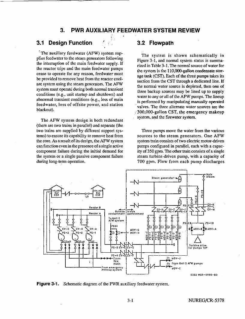
The system is shown schematically inFigure 3-1, and normal system status is summa-rized in Table 3-1. The normal source of water forthe system is the 110,000-gallon condensate stor-age tank (CST). Each of the three pumps takes itssuction from the CST through a dedicated line. Ifthe normal water source is depleted, then one ofthree backup sources may be lined up to supplywater to any or all of the AFW pumps. The lineupis performed by manipulating manually operatedvalves. The three alternate water sources are the300,000-gallon CST, the emergency makeupsystem, and the firewater system.
Three pumps move the water from the varioussources to the steam generators. One AFWsystem train consists of two electric motor-drivenpumps configured in parallel, each with a capac-ity of 350 gpm. The other train consists of a singlesteam turbine-driven pump, with a capacity of700 gpm. Flow from each pump discharges
S252 WSR-0690-OD
Figure 3-1. Schematic diagram of the PWR auxiliary feedwater system.
3-1 NUREG/CR-5378

AFW System.Review
Table 3-1. PWR AFW system component status and support system dependency summary.
Support systemdependency
Response tosupport system
failureComponent Normal status
Pumps
MDP-A
MDP-B
TDP
Standby
Standby
Standby
ac Bus 1Hdc Bus IA
ac Bus 1Jdc Bus lB
Main Steam
Failure to startor run
Failure to startor run
Failure to startor run
Motor Operated Valves
MOV-A, -C, -E
MOV-B, -D, -F
MOV-G
MOV-H
MOV-I
MOV-J
Normally open
Normally open
Normally closed
Normally closed
Normally closed
Normally closed
ac Bus IH
ac Bus IJ
ac Bus IH
ac Bus IJ
ac Bus 2H
acBus2J
Fails as is
Fails as is
Fails as is
Fails as is
Fails as is
Fails as is
Air Operated Valves
AOV-A
AOV-A
Normally closed
Normally closed
Instrument Airdc Bus IA
Instrument Airdc Bus IA
Fails openFails open
Fails openFails open
through a unique discharge isolation check valve(CV-A, -B, or -C) and then joins flow from theother pumps in the two combined flow headers(PS-4 and -5). Normally open manual isolationvalves can be used to isolate any pump fromeither of the combined flow headers.
A cross-connect tap on each combined flowheader allows flow from one or both of the headersto be sent to the other unit. The taps are located out-side of containment, upstream of the containmentisolation check valves. Each of the supply lines tothe opposite unit contains a normally open manual
isolation valve and a normally shut motor-operated valve (MOV) (MOV-G and -H). Flow ineach of the combined headers passes through anoutboard containment isolation check valve(CV-D or -E), through the containment wall, andthen through an inboard isolation check valve(CV-F or -G). A cross-connect tap on each com-bined flow header downstream of the containmentisolation check valves allows flow from the otherunit's AFW system to be supplied to one or bothof the combined flow headers. Backflow to theother unit-via the supply line is prevented by two
NUREG/CR-5378 3-2

AFW System Review
check valves and a normally closed MOV (MOV-Iand -J).
Flow from each of the combined flow headersbranches into six individual headers (PS-6 to -11)downstream of the supply cross-connect from theother unit. Each of the six individual headers con-tains a normally open MOV (MOV-A to -F) and astop valve. These six individual headers are thencombined in twos, one from each of the combinedflow headers, to make three new flow headers(PS-13, -14, and -15). One each of the three newflow headers is used to feed one of the three steamgenerators via the normal feedwater piping.Backflow from the normal feedwater system isprevented by a check valve (CV-H, -I, and -J) ineach of the three AFW headers. The AFW flowtaps into the feedwater line with no valvesbetween the tap and the steam generator.
3.3 Support SystemsNumerous systems support the successful oper-
ation of the AFW system. Table 3-1 contains asummary of support system dependencies andresponses to failure. Suction water is normallysupplied from the condensate system, but may alsobe supplied from an emergency makeup system orfrom the fire main. Electrical motive power issupplied to the motor-driven AFW pumps fromthe ac emergency power busses. Bus 1H suppliesthe 3A pump, and Bus 1J supplies the 3B pump.Motive power in the form of steam is supplied tothe turbine-driven AFW pump from each of thethree steam generators. The supply lines (PS-15,-16, and -17) tap off the main steam lines betweenthe steam generators and the main steam isolationvalves (see schematic in Figure 3-1). The three taplines combine into a single header and then splitinto two lines (PS-18 and -19), each of which con-tains an air-operated valve (AOV-A and -B) that isnormally closed, but will open to start steam flowto the turbine-driven pump; Emergency dc powercan be supplied to control all the pumps. Bus IAsupplies control power for the 3A pump, andBus lB supplies control power for the 3B pump.Failure of dc control power will fail the associated
-motor-driven pump. Busses IA and lB supply thecontrol power for the air system, which in turn sup-plies the control air for the air-operated valves thatcontrol the steam supply to the turbine-drivenAFW pump. Failure of dc power or air to theturbine-driven pump control system will cause theair-operated valves to fail open, resulting in thestart of the turbine-driven AFW pump. DC controlpower is also used to control and position themotor-operated valves in the six branch lines andin the cross-connect lines. The valves fail as is onloss of power. Finally, the automatic actuation ofthe AFW system is dependent on the actuationsignals discussed in detail in the next section.
3.4 Automatic Actuation andSystem Response
The supply circuit breakers for the motor-driven AFW pumps will receive a signal to closeand the pumps will start automatically uponreceiving any one of the following signals:
1. Safety injection actuation signal
2. Trip of the main feedwater pumps
3. Low level in any steam generator
4. Loss of offsite power.
The air-operated steam supply valves for theturbine-driven AFW pump will receive a signal toopen and the pump will start automatically uponreceiving any one of the following signals:
1. Low level in any two steam generators
2. Undervoltage on any reactor coolant systemmain pump bus.
In addition to starting the pumps, the abovesignals will also cause an open signal to be sentto all six of the normally open MOVs in the sixindividual headers.
3-3 3-3 ~~~~NUREG/CR-5378

4. COMPONENT FAILURE DATA
The process used in developing the plant-specific AFW system component failure data isillustrated in Figure 4-1. The individual stepsrepresented in the figure are described in thefollowing sections.
4.1 Component History
The first step was to obtain historical informa-tion pertaining to the components of interest.Numerous sources were available, includingmaintenance records, operating logs, and monthlysummaries. The combination of information fromall of the sources would obviously result in themost comprehensive and reliable history. Often,however, in the interest of time and money, only aselect few sources would be used. Such was thecase for this study, and only documentationobtained from the maintenance work order systemof an older, dual-unit PWR nuclear power stationwas used to develop component histories.
HistorySummary
Return toServiceDate
A very brief summary of whatrepairs were performed on thecomponent.
The day that the component wasdeclared fully operational.
Maintenance An identification numberRecord sequentially assigned to eachNumber maintenance work order.
The preceding structure represents theexpected minimum, or rudimentary, datastructure present in any given nuclear powerplant.
To facilitate development of failure data forsubsequent statistical analysis, these additionalcategories were added to the data.
ComponentType
A consistent component typedefinition)'
The maintenance records for the station weregrouped by major system, with the AFW systemrecords mixed with the main feedwater (FW) andthe emergency feedwater (EFW) system records.Plant piping and instrument diagrams were used inconjunction with the maintenance records to dis-tinguish components among these three systems.A total of 1156 AFW events were thus identifiedfor further analysis.
Classification
Replace
Number ofReplacements
A code reflecting the final classi-fication of the record as eitherdescribing a failure or describingsome other maintenance action.
A flag indicating completecomponent replacement events.
The runningreplacementscomponentnumber).
total number offor the particularlocation (mark
The data were received encoded in thefollowing data structure:
Mark Number
Component
ProblemDescription
Alpha-numeric identification forthe component. In fact, thisnumber refers to a componentlocation in the plant system.
Type name of the component.
A very brief and typically crypticexplanation of why work wasperformed on the component.
Notes on specific alterations or changes in thedata (e.g., correction of misspellings or standard-ization of formats for consistency) were main-tained in a change field, unique to each record.After the standardization, the AFW component
b. As an example, three separate, independentmaintenance activities on a single 3-in. check valvereferred to the valve as a"valve," a"checkvalve," andan "isolation valve" in the component field of themaintenance work order documentation.
4-1 NUREG/CR-5378

Component Failure Data
MODEL ACTUAL
Obtain ComponentHistory 1
Define RelevantComponent
Failure Modes
Define FailureCriteria
Apply FailureCriteria to Data
A. Used maintenance records for the feedwatersystem of an older dual-unit PWR. Recordscovered 10 years of plant operation.
B. Identified AFW subset.
Used representative PRAs to identify all failuremodes that could result in loss of safety-significantcomponent functions.
Developed two sets of criteria:
1. Broad - A list of conditions that could possiblydescribe a failure, but may have described aproblem that was fixed before the componenthad to be removed from service.
2. Narrow - A list of conditions that could describethe actual occurrence of a failure (a subset ofthe broad category).
A. Reviewed all AFW system records to identifythose describing conditions satisfying thebroad criteria.
B. Reviewed all failures classified as broad toidentify those describing conditions satisfyingthe narrow criteria.
A. Plotted timeline of each component's failures,grouping similar components to show grosstrends.
B. Plotted cumulative failure curves by failuremode.
Construct FailureTimelines and
Cumulative FailureCurves I
,
LF91 0312
Figure 4-1. Process used to develop component failure data.
NUREG/CR-5378 4-2

Component Failure Data
event records were sorted and then segregatedinto 12 major component groups, as shown inTable 4- 1.
Table 4-1. Distribution of raw maintenanceevents for the AFW system according tocomponent type.
NumberComponent type of events
Steam-driven pump (TDP)
Motor-driven pump (MDP)
3-in. motor-operated valve (MOV)(individual feed header isolation)
6-in. motor-operated valve (MOV)(cross-connect header isolation)
l-in. check valve (CV)(pump recirculation)
3-in. check valve (CV)(individual feed header)
4-in. check valve (CV)(pump discharge header)
6-in. check valve (CV)(pump discharge header)
190
262
354
54
11
44
11
9
28
4.2 Definition of RelevantComponent Failure Modes
A list of 15 component failure modes (basicevents) was developed from a survey of the AFWmodels contained in three representative PRAs.Table 4-2 lists these AFW component failuremodes. The component numbers can be matchedto the component locations on the AFW systemschematic shown in Figure 3-1. Because the datawere incomplete, we made no attempt to quantifythe two failure modes involving unavailabilityresulting from testing or maintenance. Theremaining 13 modes were considered in the failureevaluations described in Sections 4.3 and 4.4.
The system boundaries used to establish thefailure modes in Table 4-2 are basically evident byinspection of the modes. The following specificground rules were used to develop the componentboundaries in the NUREG-1150 PRA (USNRC1989) and to develop the failure criteria in thefollowing section:
* Assume pump and valve breakers andcontrol circuits are part of the component
* Model ac and dc power to the breaker andcontrol circuits as a separate support systemand, thus, not an AFW failure mode.
4.3 Definition of Failure CriteriaFailure modes for the components of the AFW
system were described in the previous section.The interpretation of the maintenance records todetermine which ones indicated the presence of afailure was subjective. Because the information inthe records was not designed for the developmentof failure tracking, the information was impreciseconcerning the exact condition of the component.In order to bracket this subjectivity and to facili-tate a more repeatable analysis, or comparisonwith similar analyses, it was necessary to developa set of criteria to define when a failure mode wassatisfied. To cover the spectrum of events thatmight reasonably be considered failures, two setsof criteria were developed for each failure mode.
6-in. check valve (CV)(combined feed header)
Stop valves (various) 61
Piping (various)
Instruments (various)
111
21
Total 1156
4-3 NUREG/CR-5378

Component Failure Data
Table 4-2. AFW system component failure modes, descriptions, and relevant component numbers,corresponding to Figure 3-1.
Failure mode Description
AFW-ACT-FA-PMP-* No actuation signal to pump. *MDP-A, -B
AFW-ACT-FA-* No actuation signal to steam supply valve. *AOV-A, -B
AFW-AOV-LF-* Loss of flow through steam supply valve. *AOV-A, -B
AFW-CKV-FI-* Check valve fails to open. *3 in. CV-H, -I, -J; 4 in. CV-B, -C; 6 in. CV-A,-D, -E, -F, -G; Main Steam, 3 in., CV-K, -L, -M.
AFW-CKV-OO-* Backflow through pump discharge check valve. *CV-A, -B, -C
AFW-MOV-PG-* Motor-operated valve plugged. *MOV-A, -B, -C, -D, -E, -F
AFW-PMP-LK-STMBD-* Undetected, simultaneous leakage through one of the followingcombinations of check valves: [At least one of CV-H, -I, -J] and [eitherCV-D and -F or CV-E and -G] and [CV-A for *TDP or CV-B for *MDP-A;CV-B or CV-C for *MDP-B].
AFW-PMP-FR-* Pump fails to run. *TDP, MDP-A, -B
AFW-PMP-FS-* Pump fails to start. *TDP, MDP-A, -B
AFW-PMP-TM-* Pump unavailable due to testing or maintenance.*TDP, MDP-A, -B
AFW-PSF-FC-XCONN-* Flow diversion to opposite unit through motor-operated valves.*MOV-G, -H, -I, -J
AFW-PSF-LF-* Faults in pipe segments. *Various pipe segments.
AFW-TNK-VF-CST Insufficient water available from 11 0,000-gal condensate storage tank.
AFW-XVM-PG-XV-* Manual valve plugged. *Various manual valves.
AFW-*-TM-* Component unavailable due to testing or maintenance. *Any AFWcomponent in testing or maintenance when it is required to be in service.
* Refers to the components listed at the end of the associated description. For example, the two failure modes corre-sponding to the first entry of the table are AFW-ACT-FA-PMP-MDP-A for motor-driven pump A and AFW-ACT-FA-PMP-MDP-B for pump B.
NUREG/CR-5379 -4-4

Component Failure Data
The first set of criteria was developed for whatis called a "broad" definition of failure. The crite-ria consist of conditions that could possibly havedescribed a failure, but which may have describeda problem that was fixed before the componenthad to be removed from service. For example, afailure record for steam-driven pumps was con-sidered to describe a broad failure if it stated oneof the following:
1. Conditions existed that led to the repair ofthe lubricating oil cooling system.
2. Conditions existed that led to a bearingrepair or replacement.
3. Conditions existed that led to the repair ofthe trip/governor valve.
4. Conditions of high vibration existed.
5. Conditions existed that led to the repair ofthe pump for some unspecified reason.
6. Conditions existed that led to a controlsystem repair.
7. Pump failed to start or run.
Records that were not considered as failures bythe broad definition included those resulting frompreventive maintenance programs (includingplanned overhauls), design changes, functionallyunimportant boundary leaks, gauge replacements,and minor deficiency repairs. Also removed werefailures that resulted directly from improperlyperformed maintenance, such as a failure of theturbine-driven feed pump from overpressuriza-tion caused by an improper valve lineup during asurveillance test.
The second set of criteria was developed for a"narrow" definition of failure. The criteria consistof those conditions considered to describe theactual occurrence of a failure. These failuresresulted either in an automatic loss of componentfunction or the immediate manual removal of thecomponent from service to avoid damage. Forexample, a failure record for steam-driven pumps
was considered to describe a narrow failure if itstated one of the following:
1. The pump failed to start or run.
2. A gross loss of lubrication occurred.
3. The governor valve did not open.
4. Gross vibration occurred.
The narrow failures are a subset of the broadfailures. Risk can be quantified with the narrowdefinition of failure (using data describing fail-ures that certainly took place) to avoid the mask-ing effect caused by information in which lessconfidence is placed. At the same time, risktrends can be identified with the broadly definedfailures that should be investigated further tocheck their validity. Setting these criteria was notsimple and involved some iteration with theirapplication.
4.4 Application of FailureCriteria to the Data
4.4.1 Broadly Defined Failure Data. The 1156records were evaluated carefully to determinewhich ones indicated that a broadly defined failurehad occurred. There were 163 broad failurerecords identified in the maintenance events dis-tributed across component types, as indicated inTable 4-3. These 163 records were reduced to118 failure events distributed across failuremodes, as indicated in Table 4-4. The reductionoccurred because, on occasion, several mainte-nance records described the same failure event.Note that evidence of only 6 of the 13 failuremodes was found in the documentation. Thefollowing paragraphs describe the logic employedin evaluating the maintenance data for broadlydefined failures, as well as the logic for classifica-tion of the remainder of the events as non-failures.Table B-1 in Appendix B lists the AFW recordsgrouped by component type, indicating failureclassification by record. Table 4-5 is a shortsample of entries from Table B- 1. In Table B-2 ofAppendix B, all the non-failure records in
4-5 NUREG/CR-5378

Component Failure Data
Table 4-3. Distribution of broadly definedfailure occurrences according to component type.
Number ofComponent type failure records
Table 4-4. Distribution of broadly definedfailure occurrences according to failure mode.
Number ofFailure mode failures
AFW-ACT-FA-PMP 0Steam-driven pump (TDP)
Motor-driven pump (MDP)
3-in. motor-operated valve(MOV) (individual feed headerisolation)
6-in. motor-operated valve(MOV) (cross-connect headerisolation)
3-in. check valve (CV)(individual feed header)
4-in. check valve (CV)(pump discharge header)
28
27AFW-ACT-FA 0
AFW-AOV-LF 045
AFW-CKV-FT 0
AFW-CKV-OO 12, Oa
15 AFW-MOV-PG 41
AFW-PMP-LK-STMBD 2
AFW-PMP-FR-MDP 1118
-TDP 24
8 AFW-PMP-FS-MDP 16
-TDP 0
6-in. check valve (CV)(pump discharge header)
6-in. check valve (CV)(combined feed header)
Stop valves (various)
6 AFW-PSF-FC-XCONN 12
AFW-PSF-LF 0
16
0
AFW-TNK-VF-CST 0
AFW-XVM-PG 0
118, 106aTotal
Piping (various) 0
Instruments (various) 0a. Twelve events were initially classified as back-flow failures of check valves. After discussion withpersonnel from the power station, these events were allreinterpreted as non-failures. See Section 6.2.3.Total 163
Table B-1 have been removed, and only therecords fitting the broad definition of failureremain. Table 4-6 is a sample portion of recordsfrom Table B-2. To assist further in the evaluationof the failures, the "Problem Description" and"History Summary" sections for each of the
163 broadly defined failures were rewritten in amore readable format as the "Problem/RepairSummary." Table B-3 in Appendix B contains therewritten records, and a sample portion is shownin Table 4-7. (Refer to Appendix B for the specificrecords described in the following discussion.)
NUREG/CR-5378 4-6

Table 4-5. Sample of maintenance records for the AFW system steam-driven pumps (excerpted from Table B-1).
Maintenance Return to serviceMark request Mode/mechanism (if applicable) datea/
number Component number Problem description history summary classification'
1-TDP1 -TDP
I-TDP1-TDP
2-TDPI-TDP
2-TDP1-TDP1-TDP
A41- 1-TDP_J 1-TDP
1-TDP1-TDP1-TDP2-TDP1-TDP
1-TDP
1-TDP2-TDP1-TDP
PumpPump
ValvePump
PumpTurb
PumpPumpPumpPumpPumpTurbInstrPumpPumpValve
Pump
PumpInstrInstr
801010430803030420
10176160901030450
901261550810040500
902131328905021900905181332902040100905101032811030530910201310911011230902201305910201305
Gross oil-low discharge pressureExcessive discharge PREE-PT15
Body to bonnet leakGov valve will not control pumpspeedRefuel PMSVarious repairstrip valveOil cooler end bell crackedDrain, clean, inspect sump refillSight glass has oil leakHead gasket leaks on pumpAdjust packingGovernor valve inoperativeReplace gauge and repair leakOil leak on pumpPMS as per MMP-P-FW-004Replace handwheel
Renewed thrust bearing liningsReduced speed of Pump atgovernorRenewed bonnet gasket
Fixed satisfactoryDid PMS checksRepaired and tested governor
VoidDrained oil, cleaned sumpTightened sight glassVoidVoidVoidReplaced gaugeRepaired Pump and held pm checkVoidFound handwheel to be properlyinstalledRenewed thrust bearingthrowing oilRenewed thrust shoeReplaced glassInstalled new switch
780111 FR780303 FR
780508 BL
790204 FR790228 PMS790420 FR
790420 VOID790515 PMS790611 MD790917 VOID790917 VOID791002 VOID791102 GAUGE791116 MD791128 VOID791209 MD
791223 FR
800210 FR800319 MD800429 FR
912172125 Outboard pump bearing
124070821914284131129
Oil seal packing leakDeficiency punch listBroken case switch
LIV
00
Q0
0
.0
b
a. Note that date format is year, month, and day.
b. PMS - preventive maintenance; BL - boundary leak; VOID - record voided; MD - minor deficiency; GAUGE - gauge replacement or calibration; FR - failureto run.

Qo4
00
00
Table 4-6. Sample of maintenance records broadly classified as failures for the AFW system steam-driven pumps (excerpted from Table B-2).
Maintenance Return to serviceMark request Mode/mechanism (if applicable) datea/
number Component number Problem description history summary classificationb
1-TDP Pump 801010430 Gross oil-low discharge Renewed thrust bearing linings 780111 FRpressure
1-TDP Pump 803030420 Excessive discharge Reduced speed of pump at governor 780303 FRPREE-PT 15
1-TDP Pump 901030450 Gov valve will not control Fixed satisfactory 790204 FRpump speed
1-TDP Turb 810040500 Various repairs Repaired and tested governor trip valve 790420 FR1-TDP Pump 912172125 Outboard pump bearing Renewed thrust bearing 791223 FR
throwing oil1-TDP Pump 1240708 Oil seal packing leak Renewed thrust shoe 800210 FR1-TDP Instr 4131129 Broken case switch Installed new switch 800429 FR2-TDP Pump 11170730 Overspeed trip valve trips Straightened linkage 801118 FR2-TDP Pump 205081945 Governor set at 4060 RPM Reset RPM to 3880 820513 FRl-TDP Pump 208132145 Repair oil leak Changed thrusted shaft collar journal 820824 FR2-TDP Governor 212061305 Repair feedback arm Reinstalled setscrew 821207 FR2-TDP Pump 302111050 Pump trips Adjusted overspeed trip 830216 FR2-TDP Pump 303101430 Set screw missing Adjusted damper 830314 FR2-TDP Pump 303181232 Overspeed trip Put spring back on hook 830321 FR2-TDP Pump 304250400 Oil seal leaking Replaced bearing and thread shoes 830429 FR2-TDP Bearing 306200726 Replace bearing Replaced bearing and shoes 830927 FR2-TDP Pump 309271700 High bearing vibrations Adjusted linkage 831013 FR1-TDP PMPGov 312311328 Repair governor Installed new seat 840111 FR2-TDP Switch 402240947 Pump will not cut off in auto Checked switch 840330 FR1-TDP Pump 14061 Mechanical linkage broken Reinserted rod and closed socket 850214 FR
ends around ball tip
a. Note that date format is year, month, and day.
b. FR - failure to run.
n-02
lt00
q*1
-t
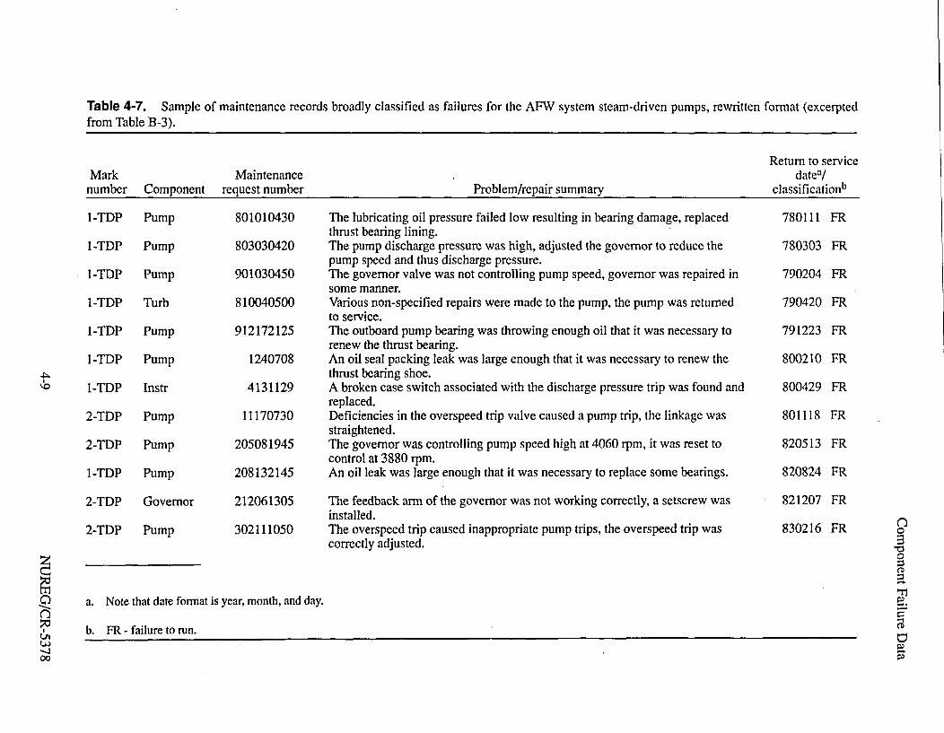
Table 4-7. Sample of maintenance records broadly classified as failures for the AFW system steam-driven pumps, rewritten format (excerptedfrom Table B-3).
Marknumber
I-TDP
1-TDP
1-TDP
I-TDP
I-TDP
I-TDP1-TDP
'O I-TDP
2-TDP
2-TDP
I-TDP
2-TDP
2-TDP
Component
Pump
Pump
Pump
Turb
Pump
Pump
Instr
Pump
Pump
Pump
Governor
Pump
Maintenancerequest number
801010430
803030420
901030450
810040500
912172125
1240708
4131129
11170730
205081945
208132145
212061305
302111050
Problem/repair summary
The lubricating oil pressure failed low resulting in bearing damage, replacedthrust bearing lining.The pump discharge pressure was high, adjusted the governor to reduce thepump speed and thus discharge pressure.The governor valve was not controlling pump speed, governor was repaired insome manner.Various non-specified repairs were made to the pump, the pump was returnedto service.The outboard pump bearing was throwing enough oil that it was necessary torenew the thrust bearing.An oil seal packing leak was large enough that it was necessary to renew thethrust bearing shoe.A broken case switch associated with the discharge pressure trip was found andreplaced.Deficiencies in the overspeed trip valve caused a pump trip, the linkage wasstraightened.The governor was controlling pump speed high at 4060 rpm, it was reset tocontrol at 3880 rpm.An oil leak was large enough that it was necessary to replace some bearings.
The feedback arm of the governor was not working correctly, a setscrew wasinstalled.The overspeed trip caused inappropriate pump trips, the overspeed trip wascorrectly adjusted.
Return to servicedatea/
classificationb
780111 FR
780303 FR
790204 FR
790420 FR
791223 FR
800210 FR
800429 FR
801118 FR
820513 FR
820824 FR
821207 FR
830216 FR
O
IV(!hW__J00
nIToEl
ITI
W.
Pa
a. Note that date format is year, month, and day.
b. FR -; failure to run.

Component Failure Data
Main AFW Steam-Driven Pumps (AFW-PMP-FR-TDP and AFW-PMP-FS-TDP). Afailure record was considered to describe a broadfailure if it stated one of the following:
1. Conditions existed that led to the repair ofthe lubricating oil cooling system.
2. Conditions existed that led to a bearingrepair or replacement.
3. Conditions existed that led to the repair ofthe trip/governor valve.
4. Conditions of high vibration existed.
5. Conditions existed that led to the repair ofthe pump for some unspecified reason.
6. Conditions existed that led to a controlsystem repair.
7. Pump failed to start or run.
Of the 190 records, 28 were determined to fitthe broad failure category. Four of these 28 weredetermined to reflect previous failure events, andthus 24 unique failures were seen. The items elim-inated from failure consideration were 47 voidrecords, 17 packing leaks, 25 preventive mainte-nance items, 23 gauge replacements/calibrations,30 minor deficiencies, 10 design changes, sevennonfunctional failures, and three failures causedby improperly performed maintenance.
Main AFW Motor-Driven Pumps (AFW-PMP-FR-MDP and AFW-PMP-FS-MDP). Afailure record was considered to describe a broadfailure if it stated one of the following:
1. Conditions existed that led to the repair ofthe lubricating oil cooling system.
2. Conditions existed that led to a bearingrepair or replacement.
3. The motor heaters failed.
4. Conditions existed that led to the repair ofthe pump for some unspecified reason.
5. Conditions existed that led to an electricalcontrol system repair.
6. Pump failed to start or run.
Of the 262 records, 27 were determined to fitthe broad failure category. The items eliminatedfrom failure consideration were 46 void records,44 packing leaks, 52 preventive maintenanceitems, 28 gauge replacements/calibrations,55 minor deficiencies, seven design changes, andthree failures caused by improperly performedmaintenance.
3-In. MOV (Individual Feed HeaderIsolation, AFW-MOV-PG). A failure recordwas considered to describe a broad failure if itstated one of the following:
1. Conditions existed that led to an electricalcontrol system repair. (All torque switchproblems were considered failures, butadjustment of limit switches was generallynot considered a failure.)
2. Mechanical binding/obstruction was noted.
3. Valve was replaced.
4. Supply breaker tripped.
5. Valve failed to open or stay open.
Of the 354 records, 45 were determined to fitthe broad failure category. Four of these weredetermined to reflect previous failure events, andthus 41 unique failures were seen. The itemseliminated from failure consideration were66 void records, 37 pressure boundary leaks,112 preventive maintenance items, 21 seat leaks,14 limit switch malfunctions, 37 design changes,20 minor deficiencies, and two failures caused byimproper maintenance.
6-In. MOV (Cross-Connect HeaderIsolation, AFW-PSF-FC-XCONN). A failurerecord was considered to describe a broad failureif it stated one of the following:
1. Conditions existed that led to an electricalcontrol system repair. (All torque switchproblems were considered failures, but
NUREG/CR-5378 4-10
Component Failure Data
adjustment of limit switches was generallynot considered a failure.)
2. Mechanical binding/obstruction was noted.
3. Valve was replaced.
4. Supply breaker tripped.
5. Valve failed to close or stay closed.
Of the 54 records, 15 were determined to fit thebroad failure category. The items eliminated fromfailure consideration were 19 void records, oneboundary leak, 14 preventive maintenance items,one limit switch malfunction, and four minordeficiencies.
3-, 4-, and 6-In. Check Valves (Indiv-idual, Combined, and Pump DischargeHeaders AFW-CKV-FT, AFW-CKV-OO, andAFW-PMP-LK-STMBD). A failure record wasconsidered to describe a broad failure if it statedone of the following:
* For the failure-to-open mode:
The valve failed to open.
* For the backflow mode (applicable only topump discharge check valves):
1. Conditions existed that led to therepair of the valve seat or disc.
2. Seat leakage occurred.
* For the steam binding mode:
1. Conditions existed that led to therepair of the valve seat or disc.
2. Seat leakage occurred.
Of the 92 records, none indicated a failure toopen, but 14 were determined to fit the broad def-inition of backflow and 48 were determined toindicate leakage that might lead to steam binding.The 14 backflow records were a subset of therecords that contributed to steam binding. Two ofthese 14 were determined to reflect previous
failure events, and thus 12 unique failures wereseen. The remaining 44 records were eliminated:19 void records, nine preventive maintenanceitems, and 16 boundary leaks.
As noted in Table 4-2, for steam binding tooccur, one of the three 3-in. (CV-H, -I, and -J)check valves had to leak simultaneously witheither of the two 6-in. combined header checkvalves (CV-D and -F or CV-E and -G) and onepump discharge check valve (CV-A, -B, or -C). Afailure timeline containing all 48 broadly definedcheck valve failures was constructed to search forcombinations that could lead to failure (Fig-ure 4-2). Failure could have occurred on oneoccasion each for a steam-driven pump and amotor-driven pump (MDP-B), both in Unit 2.Thus, only two broadly defined occurrences ofsteam binding were observed.
1-In. Check Valves, Stop Valves, Piping,and Instruments. None of the 204 records inthese four categories were determined to be broadfailures for the following reasons: none of the stopvalves became plugged; none of the instrumentfailures caused failure of any associated equip-ment; and neither 1-in. check valves nor pipe fail-ures were modeled in the PRA. The recordsincluded minor valve deficiencies, piping supportdeficiencies, gauge calibrations/replacements,and preventive maintenance items.
4.4.2 Narrowly Defined Failure Data. A smallfraction of the maintenance narrative records(5%) contained sufficient information to fit thecategory of a narrowly defined failure. Thesewere determined by careful reevaluation of the163 broad failure records, as shown in Table B-3of Appendix B. The 72 narrowly defined failurerecords are shown in Table B-4 of Appendix B. Asample portion of Table B-4 is shown inTable 4-8. The distribution of the 72 failurerecords across component types is shown inTable 4-9. The 72 failure records were reducedto 35 failure events distributed across failuremode, as shown in Table 4-10. The reductionoccurred because, on occasion, several mainte-nance records described the same failure event.The following paragraphs present the logic used
4-11 NUREG/CR-5378

Component Failure Data
ComponentMark No. 1978 1979 1980 1981 1982 19B3 19B4 1985 1986 1987
Individual [ cheader L ic-
1-CV-DPump l-CV-F
discharge I-CV-E_1-CV-G
Combined F 1CV-Aheader L I-Cv-C
2-CV-H2-CV-H(H I
Individual 2-Cv-1header 2-CV- I W
2-CV-J2-.CV-J (R)
2-CV-D
Pump 2-CV-Fdischarge 2-CV-E
2-CV-G
Combined F 2 CV-Aheader L 2-CV-C
I i I I I I I I I
- --- ----------------- --- - -0-------- -0- ------ - - -------------------
_ ..................................................... ..................................................................................................................... .............................-
- _ .. .. .................................................-
..
_ _. .0..-1-------- ------------- --- 0 0 ----- -------- ----........................... ............ ....................................... .......................... - -_
- ------------- ----------------- --- -------------- 0------------- ------- _
- ............................................- ............................. .......................... ............ .......
_------.----------------X--------------------------------- ------ -------- --------_., _ _ . _ . . .....
.......... .. I.... .. . ... I... .. I .....
0 10 20 30 40 50 60
u Broadly defined failures Hours to failure from August 24. 1977* Narrowly defined failures - (thousands)o Broadly defined failures with component replacement
70 80 90
S252 SR-0391-O7
Figure 4-2. Failure timelines to determine the occurrence times of steam binding of the AFW systempumps.
to determine which of the broadly defined failurerecords could be classified as failures by thenarrow definition.
Main AFW Steam-Driven Pumps (AFW-PMP-FR-TDP and AFW-PMP-FS-TDP). Afailure record was considered to describe anarrow failure if it stated one of the following:
1. The pump failed to start or run
2. A gross loss of lubrication occurred
3. The governor valve did not open
4. Gross vibration occurred.
Of the 28 broadly defined failures, only ninewere determined to fit the narrow failure cate-gory. Four of these nine were determined toreflect previous failure events, and thusfive unique failures were seen. Recordsrepresenting apparently minor deficiencies not
considered to be failures were eight bearing/lubrication deficiencies, nine control valve defi-ciencies, one nonspecified pump repair, and onevibration event.
Main AFW Motor-Driven Pumps (AFW-PMP-FR-MDP and AFW-PMP-FSR-MDP).A failure record was considered to describe anarrow failure if it stated one of the following:
1. The pump failed to start or run
2. The supply breaker tripped
3. A gross loss of lubrication occurred
4. Gross vibration occurred.
Of the 27 broadly defined failures, only fourwere determined to fit the narrow failure cate-gory. Records representing apparently minordeficiencies not considered to be failures werenine lube oil cooler deficiencies, one bearing/
NUREG/CR-5378 4-12

Table 4-8. Sample of maintenance records narrowly classified as failures for the AFW system steam-driven pumps, rewritten format (excerptedfrom Table B-4).
Marknumber
1-FW-P-2
2-FW-P-2
2-FW-P-2
Component
Pump
Pump
Pump
(A-
2-FW-P-2 Pump
Maintenancerequest number
801010430
11170730
302111050
303181232
40487
41325
40450
40488
40491
Problem/repair summary
The lubricating oil pressure failed low resulting in bearing damage, replacedthrust bearing lining.
Deficiencies in the overspeed trip valve caused a pump trip, the linkage wasstraightened.
The overspeed trip caused inappropriate pump trips, the overspeed trip wascorrectly adjusted.
Failure of the overspeed trip spring to stay engaged led to a pump trip, thespring was reinstalled.
The governor valve would not open, spring was replaced but this did not help.
Governor was removed and overhauled because poor operation.(This event was combined with record 40487)
Additional governor work combined with record 40487.
Additional governor work combined with record 40487.
Additional governor work combined with record 40487.
Return to servicedatea/
classificationb
780111 FR
801118 FR
830216 FR
830321 FR
860907 FR
860927 FR
860930 FR
860930 FR
860930 FR
I-FW-P-2
I-FW-P-2
Pump
Pump
I-FW-P-2 Pump
1-FW-P-2 Pump
1-FW-P-2 Pump
00
0
0
~1
a. Note that date format is year, month, and day.
b. FR - failure to run.

Component Failure Data
Table 4-9. Distribution of narrowly definedfailure occurrences according to component type.
Number ofComponent type failure records
Table 4-10. Distribution of narrowly definedfailure occurrences according to failure mode.
Number ofFailure mode failures
AFW-ACT-FA-PMP 0Steam-driven pump (TDP)
Motor-driven pump (MDP)
3-in. motor-operated valve(MOV) (individual feedheader isolation)
6-in. motor-operated valve(MOV) (cross-connectheader isolation)
3-in. check valve (CV)(individual feed header)
4-in. check valve (CV)(pump discharge header)
9
4
22
AFW-ACT-FA 0
AFW-AOV-LF 0
AFW-CKV-FT 0
AFW-CKV-OO 07
AFW-MOV-PG 18
AFW-PMP-LK -STMBD 2
4 AFW-PMP-FR -MDP 0
-TDP 57
AFW-PMP-FS -MDP 4
6-in. check valve (CV)(pump discharge header)
6-in. check valve (CV)(combined feed header)
Stop valves (various)
Piping (various)
Instruments (various)
6 -TDP 0
AFW-PSF-FC-XCONN 6
13
0
0
AFW-PSF-LF
AFW-TNK-VF-CST
AFW-XVM-PG
0
0
0
Total 350
Total 72 1. The valve failed closed
2. The valve failed to open
lubrication deficiency, one vibration event, fourslow pump starts, three motor wetting events, andfive heater failures.
3-In. MOV (Individual Feed HeaderIsolation, AFW-MOV-PG). A failure recordwas considered to describe a narrow failure if itstated one of the following:
3. The valve was stuck (no specified direction)
4. The supply breaker tripped.
Of the 45 broadly defined failures, only22 were determined to fit the narrow failure cate-gory. Four of these 22 were determined to reflectprevious failure events, and thus 18 unique
NUREG/CR-5378 4-14

Component Failure Data
failures were seen. Records representing appar-ently minor deficiencies not considered to be fail-ures were eight control deficiencies, ninemechanical deficiencies, and six failure-to-closeevents.
6-In. MOV (Cross-Connect HeaderIsolation, AFW-PSF-FC-XCONN). A failurerecord was considered to describe a narrowfailure if it stated one of the following:
1. The valve failed open
2. The valve failed to close
3. The valve was stuck (no specified direction)
4. The supply breaker tripped.
Of the 15 broadly defined failures, only sevenwere determined to fit the narrow failure cate-gory. One of these seven was determined toreflect a previous failure event, and thus sixunique failures were seen. Records representingapparently minor deficiencies not considered tobe failures were one control deficiency, threemechanical deficiencies, and four failure-to-closeevents.
3-, 4-, and 6-1n. Check Valves (AFW-CKV-OO and AFW-PMP-LK-STMBD). Afailure record was considered to describe anarrow failure if it stated one of the following:
* For the backflow mode (applicable only tothe pump discharge check valves): grossseat leakage occurred.
* For the steam binding mode: seat leakageoccurred.
Of the 48 broadly defined failures, none weredetermined to fit the narrow category of backflowfailure, and 30 were detennined to fit the narrowfailure category for steam binding failure.Records representing apparently minordeficiencies not considered failures were 18 valveinspections/overhauls where the record did notstate that the valve had been leaking.
A failure timeline was constructed to search forthose combinations of valves leading to steambinding, as was done for the broadly defined fail-ures (Figure 4-2). Failure could have occurred onone occasion each for a steam-driven pump and amotor-driven pump (MDP-B), both in Unit 2.Thus, only two narrowly defined occurrences ofsteam binding were observed.
In summary, based on maintenance records andthe logical application of the important failuremodes modeled in the PRA, 118 broadly definedand 35 narrowly defined failures were deter-mined to have occurred in the AFW system in the10-year period. These failures were statisticallyanalyzed to determine if the rate of failure wasincreasing with time.
Finally, note that the "retum-to-service-date"was used as a surrogate for the actual date a fail-ure occurred because actual dates were not avail-able for this period of operation. In general, thereturn-to-service-date was within one month ofthe actual failure date.
4.5 Failure Timelines andCumulative Failure Curves
The timelines and cumulative failure curvescorresponding to the descriptions in the previoussections appear as Figures 4-3 through 4-19. Atime plot is simply a graphical tabulation of thefailure times. A cumulative failure curve is a plotof the cumulative numbers of failures as a func-tion of time. This plot will be an approximatelystraight line for a constant failure rate process(see Section 5.3.2). A general observation for thebehavior of the data can be derived from the time-lines and cumulative failure plots. If the failuresare largely concentrated in later years and thecumulative failure curve is therefore concaveupward, then there is a general indication ofincreasing failure rate, suggesting aging of thecomponents. If the failures are largely concen-trated in the earlier years and the cumulative fail-ure curve is therefore concave downward, thenthere is a general indication of decreasing failurerate.
4-15 NUREG/CR-5378
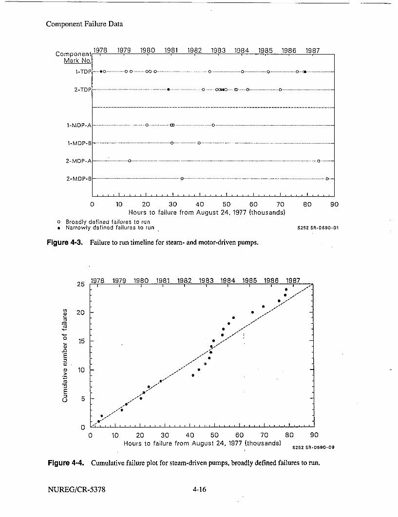
Component Failure Data
1978 1979 1980 1981 1982 1983 1984 1985 1986 1987CompoMark
1~
2.
1-MI
1-MI
2-MI
2-M
nen .: No.
-TDP o.. 00.000 0 . 0 . 0 .0- o o- - oo o ............... o - -o ... -
-TDP . --. 0 o- ... o..... .........-..... -
)P-A -...... 0 . .... 0.............. .-
DP- W.0.0. o ---------
)P-A.0......:.0.-
DP-B_.0..----------:) - ............... 0 ....... ............... ......................................................................................... .....
_00 10 20 30 40 50 60 70 80Hours to failure from August 24, 1977 (thousands)
0 Broadly defined failures to run* Narrowly defined failures to run S252 SR-0690-
Figure 4-3. Failure to run timeline for steam- and motor-driven pumps.
II
-01
1978 1979 1980 1981 1982 1983 1984 1985 1986 1987- v I , I I
LI)
._6
0,
o
-0
0,
-o
E
in0)
Co
._
20
15
10
5
.,,
* -I
- -"'a- 0-,, I _ _ ,I I . . . I
. S"
I* --I
00v
* ---,
* --0-1
* --
I
I
I .. . I .... I....I .... I....
0
Figure 4-4.
- . .. . . . . . . . . . . . . . . . .. .. . . . .
0 10 20 30 40 50 60 70 80 90Hours to failure from August 24, 1977 (thousands) SA-0690-09
Cumulative failure plot for steam-driven pumps, broadly defined failures to run.
NUREG/CR-5378 4-16

Component Failure Data
1978 1979 1980 1981 1982 1983 1984 1985 1986 19876
U)
0,
-oE
-o
EC-
5
4
3
2
1
I I I I I
-- 0 -
*
- S
0��
-o --
0 10 20 30 40 50 60 70 80 90a I a I at II a at a II a a i Ia i a a I a a a a Ia a a a I at gal i a.0
Figure 4-5.
0 10 20 30 40 50 60 70 80 90Hours to failure from August 24, 1977 (thousands) 5252 SR 0690 10
Cumulative failure plot for steam-driven pumps, narrowly defined failures to run.
1978 1979 1980 1981 1982 1983 1984 1985 1986 1987
._n
W
>-
4-0
CD-DE
0)
co
EU-
12
11
10
9
8
7
6
5
4
3
2
1
0
I I I I I I I I I ,a 0-
6/ -
S, _
, _
* ,, _
-o' 0
0
II
I I I 1.1 I I 1 1 I I I I 1 1 I 1 1 1 I I I I I I I I I I I. I . . . . . . .II-, . . .. . .1 . . .i . .a
0 10 20 30 40 50 60 70 80 90Hours to failure from August 24, 1977 (thousands) S252 SR-0690-11
Cumulative failure plot for motor-driven pumps, broadly defined failures to run.Figure 4-6.
4-17 NUREG/CR-5378

Component Failure Data
1978 1979 1980 1981 1982 1983 1984 1985 1986 1987ComponentMark No.
1-TDP
2-TDP
1-MDP-A
1-MDP-B
2-MDP-A
2-MDP-B
_ .................................................... ........................................... ........ ............................................................................................. ......... .....
_ --.. ... -.... ..... ........ ......... .... .... ..... ........ .... ..... ..-.......... -. .... .... ..... .... .. ...... .... .... .... ..... .... .... ..... .... .... ......... .... . ... ..... .... .... ....-. ............................. . . 0 .... 0 .
.. 0 Id ... I .... ..... . ... I.... I.... I ....
0 10 20 30 40 50 60 70Hours to failure from August 24, 1977 (thousands)
o Broadly defined failures to starto Narrowly defined failures to start
Figure 4-7. Failure to start timeline for steam- and motor-driven pumps.
80 90
S252 SR-0690-01A
1978 1979 1980 1981 1982 1983 1984 1985 1986 1987
._
0
0)
.
0(-)
17161514131211
1098765432l
n)
-
. . . . . . . . .
I I I I I 1 I -.
�0�
S
-5-
*
* -
S --
* --
* --
S --
9--
S --
�8
- -- S0 10 20 30 40 50 .60 70 80 90
ii. ii, I, I r p H I H I i i I I i a I I I Iv
0 10 20 .30 40 50 60 70 BO 90Hours to failure from August 24. 1977 (thousands) S252 SR-0890-12
Cumulative failure plot for motor-driven pumps, broadly defined failures to start.Figure 4-8.
NUREG/CR-5378 4-18

Component Failure Data
1978 1979 1980 1981 1982 1983 1984 1985 1986 19875
to
co
0
C)E
a)
EC-,
4
3
2
1
I I I
S -'
S -
-- S
S
I I p I I I p0
0 10 20 30 40 50 60 70Hours to failure from August 24, 1977 (thousands)
80 90
S252 SR-0690-13
Figure 4-9. Cumulative failure plot for motor-driven pumps, narrowly defined failures to start.
ComponentMark NW. 1978 1979 1980 1981 1982 1983 1984 1985 1986 1987
I rI I I I I i I I i
1-MOV-A - ......................... .. . 0 . . . . . . . ........................................ ............... .........................-............._
1-MOV-E -...............-
1-MOV-C -.-----. o....................................
I-MOV-D . ...... .... 0. -
1-MOV-E .. ....... ._
1-MOV-f -.... I0-.... . -.. ..0.-o.-----.x
1-MOV-F(R)
2-MOV-A 4.......
2-I
2-
2-MOV-B ... ........ ..
2-MOV-C ......... .... ---------..-.... -----...-.
MOV-C(R) I..1- - --. °.-
2-MOV-D . . -............... . ...... o. . .......---.-.... ---.......--..0... . .
2-MOV-E . ........ .: .............-.o.-0.-
MOV-E(R) I . ............................. .. -
2-MOV-F -.-..............-----.--.......--. o..----------------..-..-....---..--o-o-........ . .I. . . . . . ., .I . . . . I 1,. . . .1, 1,. . . . I . . . I . . . . .1 ,. . .
0 10 20 30 40 50 60 70Hours to failure from August 24, 1977 (thousands)
O Broadly defined failures* Narrowly defined failures K Narrowlydefined failures with component replacementx Valve did not fail, it was moved to 1-MOV-E location end a new valve was installed
Figure 4-10. Plugging failure timeline for 3-in. MOVs (feed header isolation valves).
4-19 NI
80 90
5252 SR-690-03
JREG/CR-5378

Component Failure Data
1978 1979 1980 1981 1982 1983 1984 1985 1986 198742
36
30
a)
0
-oEc
>
E
FigureplugginE
- I I I I I I I I I - ,_~~~~~~~~~~~~~~~~~~~~~~~~~~~~~ I "
0 I
0 -"0"
0 104,,-
.- ,-0SI . ,,
,- I_ ,,~~~~~~~~~~~~~~~~~~~~~
24 a ,-0 --
18 ,o
12
0 lO 20 30 40 50 60 70 80 90Hours to failure from August 24, 1977 (thousands) S2.52 SR-0690-14
4-11. Cumulative failure pl ot for 3-in. MOVs (feed header isolation valves), broadly definedi failures.L7
1978 1979 1980 1981 1982 1983 1984 1985 1986 198718I
CD,
4--
0
-D
0)
co~
EM
15
12
9
6
3
,-.
,, 0
,,0'
_~~~ ~~ ,,
,, O
_ ,//.~~~~
,,.~~~
0',,,,1....S..|....g...
,--I
- I . IU . ..
0 10 20 30 40 50 60 70 80 90Hours to failure from August 24, 1977 (thousands) S252 SR-0690 t5
Figure 4-12. Cumulative failure plot for 3-in. MOVs (feed header isolation valves), narrowly definedplugging failures.
NUREG/CR-5378 4-20

Component Failure Data
1978 1979 1980 1981 1982 1983 1984 1985 1986 1987Component l 1 1 I I I I I I
Mark No.
1-MOV-G -0.0 2- - - -*-- -- --- -- - -o . o
1-MOY-HI
2-MOV
... ................................................................................................................................................ ........................... ... ........ a ...I.-0 ......................... ,@
................................ ............. .... ......... a -
.... 1;.I..I..I..I.... I....I .... I.... I....I . ...
2MOV-I(R)l
2-MOV-J
0 10 20 30 40 50 60 70Hours to failure from August 24, 1977 (thousands)
o Broadly defined failures* Narrowly defined failures u Narrowly defined failures with component replacement
Figure 4-13. Failure to stay closed timeline for 6-in. MOVs (cross-connect valves).
80 90
5252 SR-0690-02
1978 1979 1980 1981 1982 1983 1984 1985 1986 1987
U)va
c3
4-
0.,8
EC
cco
EU
13
12
11
10
9
8
7
6
5
4
3
2
1f%
I
-. '. . . I
-r' -0.
I I i I I I I I I .
0 ' -
*~ ~ ~ ~ ~ ~ ~ ~ ~
* ,,
* ,, _
*,
* * _
o -, ~: 'I, "
0
, -- ~I "
I .. .. I .. .. I. . .. I . .. .I. .. . I. .. . I0 10 20 30 . 40 , 0 , 60 , 7 , 80 , 9U/
0 10 20 30 40 50 60 70 80 90Hours to failure from August 24, 1977 (thousands) S252 SR-0690-16
Cumulative failure plot for 6-in. MOVs (cross-connect valves), broadly defined failures toFigure 4-14.stay closed.
4-21 NUREG/CR-5378

Component Failure Data
1978 1979 1980 1981 1982 1983 1984 1985 1986 1987
6 _ ,,
co0
~ 4 0 -o,,
C.) 4
a 2 _ .,E
0 . '.. .. 1...1 ..1, I I...1..1..1,
0 10 20 30 40 50 60 70 80 90Hours to failure from August 24, 1977 (thousands) S252 SRO069017
Figure 4-15. Cumulative failure plot for 6-in. MOVs (cross-connect valves), narrowly defined failuresto stay closed.
Component 1978 1979 1980 1981 1982 1983 1984 1985 1986 1987Mark No. , I I I I I X I
1-CV-A --- -a o.--
2-CV-B . -. a...
2-CV-E _-. . ... - -----o
2 -C V -A . .. .... ..... . .. .. ... .. ... .. .. .. ... .. . ..... ... ... ... ..... .......... ... ... ... ...... ................................ .. .......... ...--. .... . .a
2-C V -A .................................................................................................. o_................ 0..................... .......................... .....................................
2-CV-C -.--- oxo--
0 10 20 30 40 50 60 70 80 90Hours to failure from August 24, 1977 (thousands)
0 Broadly defined failures S252 SR-0690-04
Figure 4-16. Backflow failure timeline forpump discharge check valves. Following discussion with per-sonnel from the power station, these events were all reinterpreted as non-failures. See Section 6.2.3.
NUREG/CR-5378 4-22

Component Failure Data
1978 1979 1980 1981 1982 1983 1984 1985 1986 1987
V,
0)
.0E
a)
EC-,
13
12
11
10
9
8
7
6
5
4
3
2
1
0
a a a a a I I --
-0 -
- C -
0 --
C --
-i
- 0
- 0
- 0
C
0
0
0
a a a a I aaa.I.,aa I I I I a
0 10 20 30 40 50 60 70Hours to failure from August 24, 1977 (thousands)
80 90
S252 SR-01390-18
Figure 4-17. Cumulative failure plot for pump discharge check valves, broadly defined backflow leak-age failures. Following discussion with personnel from the power station, these events were all reinterpretedas non-failures. See Section 6.2.3.
r'nmnrannn-'- 1978 1979 1980 1981 1982 1983 1984 1985 1986 1987
Ni~r_~ - .I I I I I I I i I I
lar No.
1 -T O P ..-.... ..... .. .... .... .. .. .. . ....... ....... -..... .. .......... .... .. .... ...... ... . ... .. ........ .. ...... ... .. ..... ... .. .. ...
22 D .......................T ............................................... .............................................
-- ---M O P - A- - - - - - -- - -- - - - - -- ---...-..-- - -- - - - -- - - - -- -
1 - M O P - .... .. ... ..... .. .. .. .. .......... ... ... ..B ..... ..... .. ..... ... ... .... ... ... ... ..... ........ .I ... ... .... ... ..... ... .. .. .. ....
- M O P - A ..... .. ....... .... .. .... .. . ... ... ... ... .... ... ... .... .... ..... ..... ...... ....... .. ... ... .... .... .... ... .... .... .. .. ...... ..
.- D - ............................ ....................................................... I..................................
2
. 1. . . . . . . ..... I., ...... ..... . . .
0 10 20Hours to
* Narrowly defined steam binding
30 40 50 60 70failure from August 24. 1977 (thousands)
80 90
S252 SR-O69O-05
Figure 4-18. Steam binding failure timeline for the steam- and motor-driven pumps.
4-23 4-23 ~~~NUREG/CR-5378

Component Failure Data
1978 1979 1980 1981 1982 1983 1984 1985 1985 19873
en
co
0
-EEDC)
EU
2
I I I I I
0 -
- 70
0
0 10 20 30 40 50 60 70 80 90Hours to failure from August 24, 1977 (thousands) S252 SR 0690.19
Figure 4-19. Cumulative failure plot for the steam-defined steam binding failures.
One overall observation about this graphicaldisplay of the data is that the plots are basicallyuninformative in the cases with few failure occur-rences. In addition, it is difficult to test any com-ponent data pooling assumptions with thisgraphical display. The statistical methods dis-cussed in Section 5 are specifically designed toanalyze such sparse data and to test thehomogeneity of the (aggregated) sample ofcomponent failures.
Many of the cumulative plots, such asFigure 4-4, show little departure from a straightline, indicating that the failure rate appears to beroughly constant. This is consistent with the cor-responding timelines, such as shown in the topportion of Figure 4-3, where the failure timesappear to be uniformly scattered over time. Other
and motor-driven pumps, broadly and narrowly
cumulative plots, (Figures 4-6, 4-8, and 4-17)show clustering of the failures. In these cases, thetimelines can help clarify the kind of clusteringthat occurred. For example, Figure 4-7 shows thatthe failures tended either to occur in pairs or to berepaired in pairs. Figure 4-16 shows that threevalves were repaired for leakage almost simulta-neously, while a different valve had recurrentrepairs. The clustering in Figures 4-16 and 4-17was strong enough to motivate questioning of thepersonnel at the power station, which led to areinterpretation of the data, as described in Sec-tion 6.2.3. There are no obvious cases of increas-ing failure rate, although Figures 4-6 and 4-15may show decreasing failure rates. Sections 5and 6 present analysis approaches that are moresensitive and less subjective than simple inspec-tion of these figures.
NUREG/CR-5378 4-24

5. STATISTICAL METHODS FOR ANALYZINGTIME-DEPENDENT FAILURES
The usual assumption in PRAs is that eachcomponent has a constant failure rate A. Thisleads to familiar formulas such as I - e-i' forthe probability of failure by time t, and AWt forthe approximate probability of failure within ashort time a t .The data are said to be generatedby a homogeneous Poisson process because thenumber of failures occurring in any time t is aPoisson random variable with parameter A(t).One feature of this process is that the componentdoes not age. That is, the probability of failure ina short interval of length At, assuming that thecomponent is operable immediately before thestart of the time interval, remains the sameASt, whether the component is new or old. In aninvestigation of aging, therefore, more compli-cated models must be introduced, and the familiarformulas must be modified.
The development of such models and asso-ciated techniques of data analysis form the sub-ject of this section. For this development, we stepaway from the PWR context of the previous sec-tions, and consider the statistical methods them-selves. These methods are the basis for theanalysis in Sections 6 and 7. The topics are out-lined here without proofs or many details. Detailsabout the theory, including the necessary proofs,are given in Appendix A. Details about thenumerical methods for implementing the theoryare given by Atwood (1990). The most recent pre-sentation of the statistical methods is Atwood(1992). They are illustrated here by both real andhypothetical examples. Unless indicated other-wise, all the figures are based on the data for plug-ging of 3-in. motor-operated valves (MOVs),failure mode AFW-MOV-PG with the broad defi-nition of failure, and on the exponential failurerate model defined below.
5.1 Aging Models
The approaches used for inference about agingassume that the failures of a component follow atime-dependent Poisson process. That is,
* The occurrence of a failure in any time- interval is independent of the presence or
absence of failures in other non-overlappingtime intervals.
* The probability of a failure in a short period(t, t + A t) asymptotically approaches A(t)A tas At - 0.
* The probability of more than one failure in ashort period (t, t + At) becomes negligiblecompared to the probability of one failure asA t- 0.
Therefore, the failure process has failure rateA(t) . If A(t) is an increasing function of t, failurestend to become more frequent as time goes on. Astatistical approach can be used to decide whetherA(t) is increasing.
When applying this model to investigate aging,t represents the age of a component. It is assumedthat the form of A(t) is the same for all similarcomponents, depending only on the ages of thecomponents, not on the portion of the plant's his-tory when the components were in service. Thisin turn rests on an assumption that we makeexplicit: The environments of the components(ambient conditions, maintenance and operationpractices, and any degrading conditions) are con-stant throughout the life of the plant.
The general form assumed for A is
A(t) = Aoh(t; f)
The three specific models considered in thisreport are
A(t) = A0e fl' (exponential failure rate)
A(t) = 20 (t/to)fi (Weibull failure rate)
A(t) = A2(l + Pt) (linear failure rate)
In each model, A, is a normalizing constant,with units 1/time, and h(t;fl) is a dimensionless
5-1 NUREG/CR-5378

function of time t and a parameter P3. The value ofP determines the shape of the failure rate func-tion. The failure rate is increasing if P > 0; it isconstant if/3 = 0; and it is decreasing if P3 < 0.
For the exponential and linear failure rate mod-els, A, is the value of the failure rate at time t = 0.In these two models, P3 has units 1/time, so thatthe product Pt is dimensionless. For the Weibullmodel, t0 is some normalizing time, and P3 isdimensionless. The choice of to is arbitrary, but avalue somewhere in the range of observed valuesof t is convenient. Then A, is the value of the fail-ure rate at time to.
The analysis considers each of the threemodels. There are no theoretical reasons for pos-tulating one over the others. The data used in thisstudy, however, give much less satisfactoryresults when the linear model is used than whenthe exponential or Weibull model is used. Withthe linear failure rate model, it is not uncommonfor the MLE for P to be infinite, for the uncer-tainties to be very large, or for the normalapproximation to be unusable. In the best-behaved examples, the three models give similarestimated failure rates in the region of theobserved failures. Therefore, all three modelswere tried initially, but full results are reportedonly for the exponential and Weibull models. Theresults using these two models are similar andwould diverge only if an analyst tried to extrapo-late far beyond the time period of theobservations.
Each of the three models has its own specialcharacteristics. Under the exponential model withP > 0, the failure rate doubles every log(2)//3hours. Under the linear model the failure ratedoubles from its initial value in I1/3 hours,doubles again in the next 2//3 hours, and so forth.Under the Weibull model, the failure rate at timeO either is zero (if P > 0) or is undefined (if/ < 0). Therefore, it is not meaningful to speak ofthe failure rate doubling from its initial value.However, the failure rate doubles between times
t1 and t2 whenever (t2/tO) = 21P. As has been
mentioned, the linear failure rate model is theleast tractable of the three models. This may besurprising, but follows from the fact that both themathematical formulas and the calculated num-bers in applications are best behaved whenlogA(t) is linear in /3. This log-linearity is presentfor the exponential and Weibull failure rate mod-els, but not for the linear failure rate model. SeeAppendix A for more detail on all three models.
Some other references for the use of the modelsare as follows. Cox and Lewis (1966) give adetailed treatment of the exponential failure ratemodel when there is just one component. TheWeibull model has been explored by Crow (1974,1982 and works cited there) and Donelson (1975)and is reviewed by Engelhardt (1988). The Crowand Donelson papers derive explicit formulas forthe MLEs when all the components are observedfrom their time of installation. These formulas arealso mentioned in Appendix A, but are not usefulfor the data of this report because very few of thecomponents are observed from their time ofinstallation. Most papers on the Weibull modeluse /3-1 in the exponent, a slightly different para-meterization from the one given in this section.The parameterization with /3 in the exponent isused here because it allows the same interpreta-tion of P3 in all three models, with P3 = 0 corre-sponding to a constant failure rate. The linearmodel has been less widely used in the literature,although it is considered by Salvia (1980) andVesely (1987).
It was assumed that each component's failurerate is of the same form (exponential, Weibull, orlinear), and that the value of P is the same for allthe components. It was not assumed initially thatthe components have the same value of A.,although examination of the data for this reportalways led to the conclusion that the values of Amay be treated as all the same.
5.2 Assumptions RegardingFailure Data
Failure data for a component can arise in thefollowing ways:
NUREG/CR-5378 5-2

Statistical Methods
* A random number of failure occurrences ina fixed observation period (time-censoreddata)
Distinct components are assumed to fail inde-pendently of each other.
5.3 Inference Methods* A fixed number of failure occurrences in a
random observation period (failure-censored data)
* More complicated ways.
Time-censored data arise if the component iswatched or plant records are examined for a fixedtime period. During that time, a random numberof failures occur. At each failure, the componentis repaired (made as good as it was just before thefailure) and returned to service.
Failure-censored data arise if the component isrepaired until a predetermined number of failureshave occurred. At that time the component isremoved from service and replaced by a newcomponent. Both of these types of failure dataresult in tractable formulas for statisticalinference.
In reality, the decision to repair or replace acomponent is based on a number of consider-ations, such as the availability and cost of replace-ment components, the severity of the particularfailure mode (including the difficulty, cost, andpotential safety hazards of repair), any recent his-tory of failures, and other similar factors. Theseconsiderations are difficult to express in a simplemathematical model. Therefore, the data analysisconsidered here assumes that the data for a com-ponent are generated in one of two simple ways:if the final failure time is less than the observationtime, the data for the component are consideredtime-censored; whereas, if the final failure timeequals the observation time because the compo-nent was replaced, then the data for the compo-nent are considered failure-censored.
It is never required that components beobserved starting from the moment of instal-lation, only that each component be observedstarting at some known time, which may or maynot coincide with the component's installation.
The approach shown in Figure 5-1 is outlinedhere. (Figure 5-1 expands a portion of Fig-ure 2-2.) First, investigate the assumption that allthe components have the same value of P. If thedata show no strong evidence against thisassumption, accept that portion of the model.Then test whether Pi = 0, that is, whether the fail-ure rate is constant. If the data show evidence(statistically significant at the selected level) of anon-constant failure rate, continue with the analy-sis; otherwise, treat the failure rate as constantand stop the analysis of this set of components.
When the failure rate appears to be non-constant, investigate the assumption that it is ofthe assumed form (exponential, Weibull, orlinear). If the data seem consistent with theassumed form, investigate the assumption that allthe components have the same value of Ao If thedata show no strong evidence against thisassumption, accept that all the components have acommon A, as well as a common fl. Find theMLEs of Pi and A,, and obtain the correspondingMLE of A(t) at any t. Now investigate whether the
joint MLE of the two parameters (P,logA,,) maybe treated as having a normal distribution. If so,the approximate normality of the MLE yields anapproximate confidence interval for A(t) .
The first four steps in Figure 5-1 involve statis-tical testing, that is, looking for evidence againstthe default assumptions. As in all testing situa-tions, when the data set is small the tests have lowpower. That is, when there are few failures, therewill be no strong evidence of differences in fibetween the components, and no strong evidenceof aging, or of lack of fit to the model, or of differ-ences in A0. Thus, small data sets typically giveno reason to discard the usual PRA model of aconstant failure rate that is the same for all similarcomponents.
Statistical inference is generally based on thelikelihood function, which depends on the data
5-3 NUREG/CR-5378

Statistical Methods
Consider Splitting Data
Stop
Try New Model
Consider Splitting Data
Use ConservativeBound or New Model
LF91 0311
Figure 5-1. Approach for statistical analysis of one data set.
NUREG/CR-5378 5-4

Statistical Methods
and on the parameter(s). Inference for fi is of pri-mary interest in a study of aging, because it is fithat determines whether the failure rate is increas-ing. It is shown in Appendix A that the condi-tional likelihood can be used to perform inferencefor fi, without assuming that the components nec-essarily have a common value of A, and withoutestimating either the single Ao, or all the A),s. Theconditional likelihood is defined as the probabil-ity density of the non-replacement failure times,given the failure counts for time-censored com-ponents and given the final failure times forfailure-censored components. As shown inAppendix A, if the components are not assumednecessarily to have the same value of A,, and ifthe components are all time-censored, there arestrong theoretical grounds for using the condi-tional likelihood. In other cases, some informa-tion about fi is lost by using the conditionallikelihood.
Therefore, the first exploratory analysis used toverify assumptions of the model is based on theconditional likelihood. In this way the first foursteps in Figure 5-1 are carried out without assum-ing that there is a common A, Later, when bothparameters must be estimated simultaneously toproduce an estimate of the failure rate A(t) at var-ious times t, the full likelihood is used.
All the computations were carried out by thecomputer code PHAZE, documented by Atwood(1990). The portions of the approach just outlinedare described in more detail in the next sections.
5.3.1 Inference for Pi.
Estimation and Confidence Intervals for fi.Appendix A gives formulas for the conditionallikelihood of the non-replacement failure times,conditional on the failure counts or the finalreplacement failure times, whichever is random.This conditional likelihood depends only on P,not on the (possibly different) values of A, for thecomponents. Therefore, P can be estimated whileA, or the Aos are ignored. Based on L(P), the log-
arithm of the conditional likelihood, the MLE /3is the value satisfying
(d/dP)L(3) = 0,
and can be found by numerical iteration.
Let P3 be the true value governing the failurerate. Then (didf)L(/3) has expectation 0 andvariance denoted by 1(X5), calculated by formu-las given in Appendix A. The distribution of(didfl)L(/P) is asymptotically normal by the Cen-tral Limit Theorem. Therefore, an approximateconfidence interval for P3 is the set of all p% suchthat
(d/d/3)L~i0o)/[lfi0) l /2 (5-1)
lies in the interval (-c, c), where c is the appropri-ate number from a normal table; for example,c = 1.645 yields an approximate 90% confidenceinterval.
When the linear failure rate model is used witha small data set, it is not uncommon for the MLE,or at least for one end of the confidence interval,to be infinite. This is one reason for preferring theexponential or Weibull model.
Component Comparisons for P3. Considerthe possibility that the different components havedifferent values of /l . Let Pi denote the actual
value of P3 corresponding to the jth component. Itis estimated by using only the data from onecomponent.
A visual comparison of the components can bemade by plotting confidence intervals for the var-ious /3j values, each interval based only on datafrom a single component. Two examples areshown in Figures 5-2 and 5-3. If the intervalslargely overlap, as they do in Figure 5-2, then thedata are consistent with the assumption that the Pivalues are all equal.
If one or more confidence intervals are clearlyshifted away from the others, as for components 8and 9 in Figure 5-3, then those few componentsare evidently aging at a different rate from theothers.
5-5 NUREG/CR-5378

Statistical Methods
C0
£0
00
I -MOV-A1 -MOV-B i1 -MOV-C1 -MOV-D1 -MOV-E1 -MOV-F
1 -MOV-F(R)2-MOV-A2-MOV-B2-MOV-C
2-MOV-C(R)2-MOV-D2-MOV-E
2-MOV-E(R)2-MOV-F
OVERALL
-5.01E-4
I I
a a *-
* MLE(J)n MLE(-])* MLE
9E% Conf. Int.
0.600.110.960.063
0.800.23 u0.64 O0.58 U0.55 =
1 0.30 '0.41 ')0.66
0.92
0.83
7.5 E-4
i " v
"H
-2.51E-4 0.0E0 2.5E-4j3 (1 /h)
5.0E-4
Figure 5-2. Component comparisons for PB.
COMP1
COMP2
COMP3
COMP4
COMP5
0 COMP6C0°. COMP7Eo COMP80
COMP9
COMP10
OVERALL
i *E I
V
I .3
0.52
0.14
0.62
0.85
0
0.75 a0
0.67 %
0.08 o
0.007
0.73
0.065
2.5E-4
v
* MLE()* MLE(-J)* MLE
- 95% Conf. Int.
I I I . I I
1-4
HN
* I -. - .
-5.0E-4 -2.5E-4 013(I1/h)
Figure 5-3. Component comparisons for ,B, based on hypothetical data.
NUREG/CR-5378 5-6

Statistical Methods
These anomalous components are called "out-liers." At the end of this section we mention thatengineering judgment must play a decisive role inthe subsequent treatment of outliers. Of course,no confidence interval for Pi can be calculated ifthe component has no observed failures or if theonly observed failure resulted in replacement ofthe component. This is why some of the compo-nents have no associated interval in Figures 5-2and 5-3.
is used, as described in Section 6.1 of Appen-dix A.
When making multiple comparisons, as herewhen a comparison is made for each component,it is necessary to recognize that some values willappear extreme just because of random scatter.One way to account for this fact is with theBonferroni inequality, discussed in many textsand by Alt ( 1982). In the present context, for anynumber c it says that
A more quantitative comparison can be per-formed by considering
A A
Here P,/ is the MLE of /3g. based on the data from
only the jth component. The quantity /3 . is the
overall MLE of /3, assuming that the componentshave a common ,8 and using all the data exceptthe data from component j. Because the estima-
A A
tors /, and ,Bj are based on different data, theyare statistically independent, and therefore thevariance of their difference is the sum of theirvariances. If in fact all the values of Pij are equal,
then the random variable Zj, defined asA A A A
will have mean 0 and variance 1. Here s.d.()denotes the standard deviation of the quantity inparentheses. A large observed absolute value ofZ4 gives evidence that ij is different from the
average fi for the components other than the jth.The significance level for the component is theprobability that Z, would be as far from zero asactually observed, if in fact all the componentshave the same / . Figures 5-2 and 5-3 illustrate
A A
this: if /, is far from /3_., compared to the length
of the confidence interval for fj, the significance
level, shown at the right edge of the figure, issmall. If the two MLEs are close, the significancelevel is large. The significance is based on thenormal approximation. When component j hasonly one non-replacement failure, the normalapproximation is clearly poor and a better method
P (at least one of k significance levels is < c) < •c.
The inequality is close to equality when kc issmall. Therefore, the overall significance levelfor testing equality of the Pjs is the number of
components examined times the minimum signif-icance level calculated for a component. A smallvalue of the attained overall significance level(say 0.05 or smaller) shows that there is strongevidence against the hypothesis that all the com-ponents have the same value of / . The overallattained significance level is shown in each ofFigures 5-2 and 5-3.
The decision of what to do with an outliershould rest on engineering understanding of thepossible causes of the anomalous behavior, notmerely on statistical calculations. The statisticalquantities may stimulate an engineer to discover apreviously unrecognized difference between theoutlying component and the others, justifying asplit of the data. In other cases, careful engineer-ing consideration of the components may lead toconfidence that the components have no impor-tant differences, that the anomalous data justresulted from randomness; in such cases, the datawould not be split.
Testing Whether /3 = 0. Suppose that, basedon the analysis described above, we are willing toassume that the components have a common P.To test the hypothesis /3 = 0, the test statistic (5-1 )can be used with P, = 0, and the hypothesisrejected if the test statistic is in an extreme tail ofthe normal distribution. This is equivalent torejecting the hypothesis if 0 is not within theconfidence interval. The form of the test statisticdepends on the assumed model. When the
5-7 NUREG/CR-5378

Statistical Methods
exponential or linear failure rate model isassumed, the test statistic (5-1) becomes
[=(ti- j)]I/(.nj rj 2 /12)'/ 2 (5-2)
where tij is the ith non-replacement failure of thejth component, Yj is the midpoint of the observa-tion period for the component, and the range rj isthe length of the observation period. If the statis-tic (5-2) is positive and far from zero, there is evi-dence of an increasing failure rate. This test wasfirst proposed by Laplace (Bartholomew 1955).
When the Weibull failure rate model isassumed, statistic (5-1) takes a different form. Inthe case when every component is observed start-ing from its installation time, the test statisticbecomes
2 [1 + log(tjlrj)]/(Znj)12
In the general case, the test statistic can be builtfrom formulas given in Appendix A.
Although each test statistic has been motivatedand derived based on a particular model, itsasymptotic null distribution, normal(O,1), holdsunder the assumption that /3 = 0, that is, that A(t)is constant. Therefore, either test is a valid test ofthe hypothesis of constant failure rate, even if themathematical formula governing non-constant Ais not of the assumed form. The tests differ only intheir power to detect various alternatives to theconstant failure rate model.
As mentioned in Section 2.5.1, a confidenceinterval provides information that a test resultdoes not. Therefore, in addition to performing thetest described here, it is helpful to find a confi-dence interval for /3 using statistic (5-1). Thisgives a range of plausible values of /3 and showswhether the uncertainty on P is small or large.
5.3.2 Investigating the Assumed ModelForm.
0-0 Plot. A Q-Q plot (see Snee and Pfeifer1983) is a visual check of the correctness of an
assumed distributional form that can be usedin many contexts. In this context, let tj < . . . < t,be the ordered observed ages at non-replacementfailures. They represent sample quantiles corre-sponding to probabilities p < .. . < p,, with pi setto i/(n+1). For example, the median of the tis cor-responds to pi = 0.50. Let F denote the assumedcumulative distribution function, using estimatedvalues for any unknown parameters. This F is theconditional distribution of the non-replacementfailure times, conditional on the failure countsand the replacement times. The expression for anestimate of F is given in Section 6.3 of Appen-dix A. The Q-Q plot is a plot of F-'(pi) versus ti,for i from 1 to n. The name "quantile-quantile"stems from the fact that F-'(pi) is the model-basedestimate of thepi-quantile, and tj is a nonparamet-ric estimate of the same quantile. The plot is use-ful as a check of the assumed form of F, becauseif the data really arise from F, the points of theQ-Q plot fall approximately on a straight line.Pronounced curvature or other departures fromstraightness should arouse suspicions about thecorrectness of the assumed form F. Figures 5-4and 5-5 illustrate two Q-Q plots, with Figure 5-4showing good fit to the assumed model and Fig-ure 5-5 giving reason to question the model.
It is interesting to note that the cumulative fail-ure plots given in Section 4.5 are equivalent toQ-Q plots. In those plots, the observed failuretimes are expressed as calendar hours from thebeginning of the observation period, not as age ofthe components from their installation, but this isonly a trivial difference. The number of compo-nents under observation at any time is constantbecause any component that is removed from ser-vice is immediately replaced by another. There-fore, if all the components have the same constantfailure rate, then the failures are generated by ahomogeneous Poisson process and the randomfailure times are uniformly distributed. Theexpected failure times, F-I(p1 ), are thereforerl(n+l), 2r1(n+l), . . . , nr/(n+l), where r is thelength of the observation period in hours. Theplots of Section 4 have their points plotted on thevertical axis at 1, 2, .. . , n, which differ from theexpected failure times only by a constant factor,
NUREG/CR-5378 5-8

Statistical Methods
125.56
U)
V)
U)
0-c
0
0
-C
"0
0)
U
m 130.00* .
0 ..
I.'0..* ..
0 "9.I..
* ."0.'
Jo0
"'ia. 0, 9
'. 0
-1, :" 0
_ * .~~~~B
a,
0 ~ ~ ~ ~ I
15.36
0 1L
5.4I I I j 11 flfi II I..I .. I t..... 11 I I .................I....... 1
.8 122.53
Actual hours to failure (thousands) S252 SR-0690.21
Figure 5-4. Q-Q plot.
87.91
0
-C
0)
I0
0
C')
10
:3C.m
CO
00
0-a
0 ._.
0.06
; 92.21
'OF..
'. " a000
*
0
0
a0
0
S
I.
aS
a
.¢
4.24
0I 11 I I I 1 11 HI 11 I
_ . ..... . . = _ . _ _
Actual hours to failure (thousands) 89.39S241 CA-0590-02
Figure 5-5. Q-Q plot, based on hypothetical data.
5-9 NUREG/CR-5378

Statistical Methods
rI(n+1). Therefore, except for a relabeling of thevertical axis, the plots are Q-Q plots for investi-gating whether the components all have the sameconstant failure rate. The reason why the diagonalline was drawn from (0,0) to (rn+1) is that if thevertical axis were relabeled as is usual on a Q-Qplot, the diagonal line would go from (0,0) to (rfr).
Testing for the Form of A(t). TheKolmogorov-Smirnov test, or some other similarnonparametric goodness-of-fit test, can be used totest whether data come from an assumed distribu-tion. The data are the non-replacement failuretimes. The assumed distribution is F, used beforefor Q-Q plots and given in Section 6.3 of Appen-dix A. This test tends not to reject often enough;in statistical terminology, the Type I error issmaller than the nominal value. There are tworeasons for this: one is that the estimated , is usedto calculate F; the other is that when the compo-nents are observed over different time periods,the data resemble a stratified sample rather than atrue random sample. The fact that the test doesnot reject often enough is discussed in more detailin Section 6.3 of Appendix A.
This test can also be used to test whether all thecomponents have the same constant failure rate,paralleling the use of cumulative failure plots asQ-Q plots. The hypothesis to be tested is that/3 = 0 and that all components have the samevalue of A,. The corresponding distribution F isuniform, so no parameters need to be estimated.Therefore, the Kolmogorov-Smirnov test is anonparametric exact test of the hypothesis that allthe components have the same constant failurerate.
5.3.3 Inference for A,, Given P3. Suppose atthis point that the preceding analyses have led usto accept that the components have a common P,that P3 appears to be non-zero, and that theassumed form of A(t) is consistent with the data.It is now time to consider A,.
Estimation and Confidence Intervals for AowThe average failure rate during a component'sobservation period can be estimated as the
observed number of failures divided by the obser-vation time. If Pf is known or assumed, a calcula-tion back to time zero (or to time to for theWeibull model) can be used to estimate A), Thisis the conceptual basis for inference about Atgiven P3 . The formulas are given in Appendix A.
Component Comparisons for A, This diag-nostic check is a parallel of the comparisonmethod for if. The value of P3 now is treated as
A
known and equal to P3. We investigate whether A,is the same for the jth component and for all thecomponents except the jth. The mathematicalmethods are given in Section 6.2 of Appendix A.They are not based on normal approximations.Rather, they use the exact distributions of the fail-ure counts (for time-censored data) and of the finalfailure times (for failure-censored data).
The theory in Appendix A assumes that allcomponents have the same censoring type, eithertime censoring or failure censoring. In a typicaldata set, however, most of the components aretime censored, but a few are replaced upon somefailure and are therefore treated as failure cen-sored. To analyze such data, when component] iscompared to all the components except thefth, allcomponents are treated as if they were censoredthe way component] was. For example, if compo-nentj was replaced at the time of its third failure,then all the components, not merely component],are treated as if they were failure censored for thiscomparison. The reason is that the dominantuncertainty typically comes from the individualcomponent with its few failures rather than fromthe many other components with their manyfailures.
These individual tests can be combined usingthe Bonferroni inequality, just as when testing forequality of the Ps. A useful picture is a plot ofconfidence intervals for AO, each interval basedon data from a single component, as shown inFigure 5-6. As was pointed out when we consid-ered comparing components for P, engineeringjudgment must be used in deciding how to treatany outliers.
NUREG/CR-5378 5-10

Statistical Methods
C_00.ca
E0
0
I -MOV-AI -MOV-BI -MOV-CI -MOV-DI -MOV-EI -MOV-F
1 -MOV-F(R)2-MOV-A2-MOV-B2-MOV-C
2-MOV-C(R)2-MOV-D2-MOV-E
2-MOV-E(R)2-MOV-F
i , a -i
i, _
I, $ ..
-
_ . I
i N-
A
I * K
0.180.180.180.0941.000.120.63 C,
0.44 O0.78 C'0.97 !=1.00 a0.26 Ci
1.000.260.26
l, ._
I i N
* MLE()* MLE(-J)* MLEI-95% Cont. Int.
-
OVERALL
0.0E0
1.00I I I I I I - I- L - , -1 -1 -
5.OE-5 1 .OE-4 1.5 E-4Xo (1 /h)
Figure 5-6. Component comparisons for A,
5.3.4 Joint Inference for BothParameters and for the FailureRate.
Confidence Region for Both Parameters.Suppose that a confidence interval for j3 has beenfound. Then for each value of fi in the confidenceinterval, a confidence interval for AO can be
.found. This leads to a confidence region for(fA,), such as the one shown in Figure 5-7. If theone-dimensional confidence intervals each haveconfidence coefficient (1 - a), then the two-dimensional region has approximate coefficient(I - 2a). For example, 95% confidence intervalsfor fi and A, yield an approximate 90% confi-dence region for (fi,2 0) Figure 5-7 is based onthe exponential failure rate model with A, plottedon a logarithmic scale. The mathematical detailsare given in Appendix A, as are some other plotsbased on the exponential, Weibull, and linearfailure rate models.
Conservative Confidence Interval for theFailure Rate. For any time t of interest, a conser-
vative confidence interval for A(t) = A)Lh(t;fl) canbe constructed as follows. Find the maximum andminimum values that A(t) attains as A, and firange over the two-dimensional confidenceregion. These values are confidence bounds forA(t), with the same confidence coefficient that theconfidence region has. The interval is conserva-tive (possibly wider than necessary), because theshape of the joint confidence region was notdesigned to produce the shortest possibleintervals.
5.3.5 Joint Asymptotic Normality. Untilnow, inference has been largely exploratory, notestimating any quantities until the relevantassumptions had been tested. Therefore fi wasestimated using the conditional likelihood toeliminate the assumption of a common A2, andwhen A, was eventually estimated, it was for eachpossible assumed fi.
The viewpoint now changes. The modelassumptions have been investigated andaccepted. The goal is now to estimate the time-dependent failure rate A(t) at various times t. For
5-11 NUREG/CR-5378

Statistical Methods
2.0E-5
1.5E-5
1.0E-5
_ 5.0E-6
O.OEO
-5.OE-6
-1 .OE-5. . .. .5 6 7 8 9 2 3 4
1 0-5
Xo (1 /h)
Figure 5-7. 90% confidence region for (,A) based on conditional likelihood.
5 6 7 8
this, both parameters are estimated simulta-neously using maximum likelihood, based on thefull (not conditional) likelihood. The formulas forthe MLEs are given in Appendix A. Confidenceregions are based on the joint asymptotic normal-ity of the MLEs.
It turns out that the normal approximation isusually better when the model is parameterized interms of logA, rather than A, This was discov-ered empirically, but has heuristic justifications:for failure-censored data, the log transformationreplaces the scale parameter A, by a locationparameter; also, the log transformation helpssymmetrize the confidence intervals for A, forboth types of censoring. The MLE of (fl,logA,) isasymptotically bivariate normal, and formulas forthe asymptotic variance-covariance matrix aregiven in Appendix A.
Approximate Confidence Region for BothParameters. Based on asymptotic normality, theconfidence region for (p,logA,) is an ellipse.Equivalently, the confidence region for (P,,AO) is
elliptical when AO is plotted on a logarithmicscale.
To investigate whether the sample size is largeenough for the normal approximation to be ade-quate, we can compare the two confidenceregions for (8,AO), one calculated as in Sec-tion 5.3.;4 and the other being the confidenceellipse just described. If the two regions have sub-stantial overlap, the normal approximationappears adequate. If the two regions are quite dif-ferent, the normal approximation should not beused. Figure 5-8 shows the ellipse overlaid on theregion of Figure 5-7, assuming the exponentialfailure rate. Figure 5-9 shows the overlaid regionsbased on the same data and a Weibull failure rate.
For the Weibull model, the normalizing time t0was chosen in the middle of the observed failuretimes. In the example shown, it happens that thelower end of the 95% confidence limit for theWeibull j3 equals the theoretical lower limit of -1.This value is unattainable, but it is the lower con-fidence limit, and it forces A, to equal zero.
NUREG/CR-5378 5-12

Statistical Methods
2.OE-5
1.5E-5
1.OE-5
~.5.OE-6
O.OEO
-5.OE-6
-1.OE-5 , ,,,.. . . .5 6 7 8 9 2 3 4 5 6 7 8
1 0-5Xo (1 h)
Figure 5-8. 90% confidence ellipse for (fi,,), based on joint asymptotic normality, overlaid on theregion of Figure 5-7.
1.5
1.0
0.5
0.0
-0.5
-1.0OEO 1 E-5 2E-5 3E-5 4E-5 5E-5 6E-5
Xo (1/h)
Figure 5-9. 90% confidence regions for (, A,), based on Weibull failure rate model with to at the middleof observation periods.
5-13 NUREG/CR-5378

Statistical Methods
Therefore A, cannot be plotted on a logarithmicscale. In Figure 5-9, both parameters are plottedon a linear scale, distorting the ellipse slightly.Similar plots for the linear model are shown inFigures 5-10 and 5-11. With the linear model,time may be measured from an arbitrary origin,and the two figures show the confidence regionswhen time is measured from the component'sinstallation and when time is measured from apoint in the middle of the observation periods,respectively.
In Figure 5-8, the overlap of the two regions isquite good. The confidence ellipse is somewhatsmaller, which is to be expected because it usesall the information in the full likelihood. In Fig-ure 5-9 the overlap is also good, except when fi isnear the unattainable value of-l. In Figure 5-11the overlap is not bad, while in Figure 5-10 theoverlap is at best fair. A problem in Figures 5-10and 5- 1 1 is that the ellipse is truncated at the theo-retical limits of fi. The conclusions from theseobservations for this example are these: the nor-mal approximation appears very good with theexponential failure rate model, adequate with theWeibull model, and inadequate (because of thetruncation) with the linear model.
Similar figures for different data sets are shownin Figures 6-14 through 6-21 and in Appendix A.
Confidence Band for the Failure Rate.Recall that the failure rate is assumed to be of theform
A(t) = A)h(t;p)
so that a Taylor expansion yields.
logA(t) - logA(t) - log0A - 1ogAO
+ (8 - fi)(a/ap) log[h(t;fP)]
For the three specific models considered in thisreport we have
A A
logA(t) - logA(t) = logA0
-logA 0 + (8 -f)t
(exponential failure rate),
A A
logA(t) - logA(t) = logA0 - logA0
+ (8 - fi) log(t/t0 )
(Weibull failure rate), and
lgA A
logA(t) - logl(t) - logA. - logAO
+ (8-f)t/(1 +fit)
(linear failure rate).
The first two equations are exact. The approxi-mation for the linear failure rate model is ade-
quate if (,B - fi)t/(1 + fit) is not too large. For thiscase, let S denote the estimated standard deviation
of ,B . As a rule of thumb, the approximation may
be judged adequate if I 2St/(l + Alt)I is less than0.1, and fair if the quantity is less than 0.5. Thepossible need to keep t small may seem to restrictthe approach to times near the components' in-stallations. In fact, this is not the case because thetime origin may be assigned arbitrarily. This isallowed in the algebraic formulas, as discussed inAppendix A. The meaning of Pi and k., depend onwhich point is defined as t = 0.
Therefore, for any model and for a sufficiently
large sample, the MLE logA(t) is approximatelynormal. Let D denote the derivative
(alaP) log[h(t;fi)]
The approximate mean of logA(t) is logA(t),and the approximate variance equals
var(log A0) + D2var(fi) + 2Dcov(,B,log A)
NUREG/CR-5378 5-14

Statistical Methods
1 .5E-4
1 .OE-4
5.OE-5
O.OEO
-5.0E-53 4 5 6 7 2 3 4 5 6 7
10-5Xo (1Ih)
Figure 5-10. 90% confidence regions for (f, A) based on linear failure rate model with time measuredfrom the component's installation.
1.5E-5 r
1.OE-5 F
5.OE-6I-
O.OEO F
-5.OE-6
-1.0E-5 L2
I I I I I I I
3 4 5 6 7 8 91 0-4
vo (1/h)
Figure 5-11. 90% confidence regions for (f,A,), based on linear failure rate model with time measuredfrom the middle of observation periods.
5-15 NUREG/CR-5378
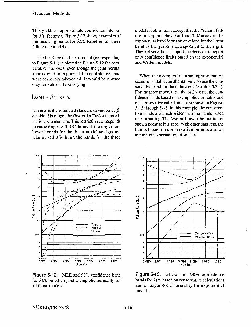
Statistical Methods
This yields an approximate confidence intervalfor 1(t) for any t. Figure 5-12 shows examples ofthe resulting bands for A(t), based on all threefailure rate models.
The band for the linear model (correspondingto Figure 5-11) is plotted in Figure 5-12 for com-parative purposes, even though the joint normalapproximation is poor. If the confidence bandwere seriously advocated, it would be plottedonly for values of t satisfying
2St/(1 + 'it) I < 0.5,
A
where S is the estimated standard deviation of fi;outside this range, the first-order Taylor approxi-mation is inadequate. This restriction correspondsto requiring t > 3.3E4 hour. If the upper andlower bounds for the linear model are ignoredwhere t < 3.3E4 hour, the bands for the three
models look similar, except that the Weibull fail-ure rate approaches 0 at time 0. Moreover, theexponential band forms an envelope for the linearband as the graph is extrapolated to the right.These observations support the decision to reportonly confidence limits based on the exponentialand Weibull models.
When the asymptotic normal approximationseems unsuitable, an alternative is to use the con-servative band for the failure rate (Section 5.3.4).For the three models and the MOV data, the con-fidence bands based on asymptotic normality andon conservative calculations are shown in Figures5-13 through 5-15. In this example, the conserva-tive bands are much wider than the bands basedon normality. The Weibull lower bound is notshown because it is zero. With other data sets, thebands based on conservative bounds and onapproximate normality differ less.
10-'1 0-4
0
-L'¢L
3
3-c
AI3L2
I's
10-5 Li10 _
7 a,
a -t-o
1 0-5
7 X-_
0.0E0 2.0E42.0E4 4.0E4 8.0E4 8.0E4Age (h)
1.0E5 1.2E5 4.0E4 6.0E4 8.0E4 i.0E5 1.2E5Age (h)
Figure 5-12. MLE and 90% confidence bandfor A(t), based on joint asymptotic normality forall three models.
Figure 5-13. MLEs and 90% confidencebands for A(t), based on conservative calculationsand on asymptotic normality for exponentialmodel.
NUREG/CR-5378 5-16
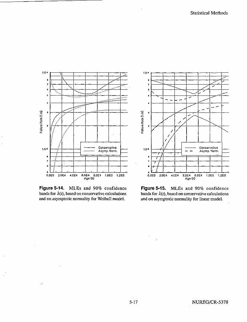
Statistical Methods
1 0-4
8
4
1 0-4
6
S
a:
'a
LI.
8,
'a
2,V
LI.
3
2
4~~~I I/ I Wt
Conservalive/ Y , _ - - Asymp. Norm.
I = I I ./ =
_| z .1 .~~~ I I I -
2
I 0-5 10-5
7 .
O.OEO 2.0E4
aa
4.0E4 6.0E4 8.0E4 1.OE5 1.2E5Age (h)
O.OEO 2.0E4 4.CE4 6.0E4 8.0E4Age (h)
1.0E5 1.2E5
Figure 5-14. MLEs and 90% confidencebands for A(t), based on conservative calculationsand on asymptotic normality for Weibull model.
Figure 5-15. MLEs and 90% confidencebands for AQ), based on conservative calculationsand on asymptotic normality for linear model.
NUREG/CR-53785-17

6. TIME-DEPENDENT FAILURE DATA ANALYSIS
The process used for analyzing the componentfailure data is illustrated in Figure 6-1, which isessentially the same as Figure 5-1 and expands aportion of Figure 2-2. The individual steps toperform the analysis are described in the follow-ing sections.
6.1 Preparation of the Input
The raw failure-time data sets developed asdescribed in Section 4 were the source of data forthis analysis. A FORTRAN computer program,PHAZE (Atwood 1990), was written to carry outthe approach presented in Section 5. A data filewas a coded representation of the failure occur-rence timeline that contained the data for each ofthe individual components as a series of records.In each record, the component name was statedfirst, then the beginning and ending dates ofobservation, followed by the specific failuredates. If a component was replaced at the end ofits observation period, then the last date of failurewas given the trailing designator, R. Tables 6-1and 6-2 present the formatted input failure datafor the broadly and narrowly defined failures,respectively. These data sets correspond exactlyto the timelines of Section 4.
6.2 Statistical ScreeningAnalysis
6.2.1 Common P Test for All Components.A single component of a nuclear safety systemwill rarely incur enough failures, even over itsinstalled life, to analyze singly. Therefore, com-ponent failure histories must be combined, orpooled, together. Pooling of component failuredata by type for use in quantification of PRAs hasbecome a casual, and sometimes untested, stan-dard practice. Good practice for data analysis,however, requires that data from the individualcomponents be examined and compared beforebeing pooled.
The pooling of component failure data is deter-mined to be acceptable or not depending on the
significance level for the test of the equality of fi(see Section 5.3.1). If the significance level wereless than 0.05 (meaning that there is less than a5% chance that such disparate component datacould arise if fi is the same for all components),then the pooling assumption would be rejectedand the significance levels and confidence inter-val plots associated with the component com-parisons would be visually checked for indicationof an outlier. Engineering judgement would beused to help decide whether to treat the outlier(s)separately.
In this analysis of AFW system components,the value of the significance level ranged from0.15 to 1.00 for all but one set of components dis-cussed separately below. The values are shownin Tables 6-3 and 6-4. Therefore, the assumptionof equality of fi was accepted, and all componentspassed this step in the screening process. Use ofthe confidence interval plots for identification ofoutliers was not necessary because all signifi-cance levels were greater than 0.05. However, tohelp the reader visualize the process, a typicalconfidence interval plot for fi is shown inFigure 5-2. The plot is shown for the 3-in. MOVs,the broad failure definition, and the failure modeAFW-MOV-PG. The overall significance level is0.83, indicating that equality of fi is a goodassumption.
One data set, AFW-MOV-FC for narrowlydefined failures, showed a significance level of0.05 based on the linear model. However theextreme component in this case had Pf= A, whichwas based on one observed failure. Therefore, wedid not feel that there was enough information tojustify any decision. Because the exponentialmodel had allowed the components to be pooled,the components were also pooled with the linearmodel.
One disturbing feature shown in Tables 6-3 and6-4 is the frequent inability of the linear modeland the occasional inability of the Weibull modelto provide an answer to the test for equality. Thisis a result of the mathematics associated with the
6-1 NUREG/CR-5378

Time-Dependent Failure Data Analysis
MODEL ACTUAL
Reformatted the failure data (Section 4) to be consistentwith the input requirements for the statistical analysiscode.
Perform StatisticalScreening Analysis
Using the statistical analysis code PHAZE:
A. Checked the adequacy of the assumption thatthe fi values for like components wereequal.
B. Tested for the presence of aging.
C. Checked the adequacy of the assumed formof the aging model (exponential, Weibull,linear) to predict the observed data.
D. Checked the adequacy of the assumption thatthe Aovalues for like components exhibitingaging were equal.
E. Found the MLEs of p and t,
F. Checked the adequacy of the bivariate normalapproximation for the construction of confidenceintervals.
Using the statistical analysis code:Calculated the value of A(t) and its associatedconfidence interval as a function of time.
LF91 0313
Figure 6-1. Process used to develop time-dependent failure rates.
NUREG/CR-5378 6-2

Time-Dependent Failure Data Analysis
Table 6-1. Formatted data used for the analysis of broadly defined failures.
Start and end NumberIn service datesa of I of
Mark number datea observations failures Datea of failure
Failure Mode AFW-PMP-FR
1-TDP 721201 77082'
2-TDP 730501 77082'
1 871001 13 780111 780303 790204 790420 791223800210 800429 820824 840111 850214860509 860820 860907
4 871001 11 801118 820513 821207 830216 830314830321 830429 830927 831013 840330850819
Failure Mode AFW-PMP-FS
1-MDP-A2
1-MDP-B
2-MDP-A
2-MDP-B
1-MDP-A
1-MDP-B
2-MDP-A
2-MDP-B
721201
721201
730501
730501
721201
721201
730501
730501
770824 871001 5 810522 830611 820320 820330 86082
770824 871001 3 810522 860826 870522
770824 871001 4 790209 790910 831006 831012
770824 871001 4 790207 790910 800725 850712
Failure Mode AFW-PMP-FR
770824 871001 5 791223 810101 810114 810201 821014
770824 871001 2 810114 820309
770824 871001 2 790324 870331
770824 871001 2 810616 870807
Failure Mode AFW-MOV-PG
1-MOV-A
1-MOV-B
1-MOV-C
1-MOV-D
1-MOV-E
1-MOV-F
1-MOV-F(R)
2-MOV-A
-MOV-B
2-MOV-C
2-MOV-C(R)
721201
721201
721201
721201
721201
721201
820815
730501
730501
730501
830427
770824 871001
770824 871001
770824 871001
770824 871001
770824 800219
770824 820814
820815 871001
770824 871001
770824 871001
770824 830426
830427 871001
1
1
1
7
1
4
2
2
4
2
1
810618
780706
830423
830411 830520 840620 850814 860128860131 861123
800219 Rb
780605 810325 811001 820814 Rb
821018 850213
781015 851029
800826 801104 821218 850620
811207 830426 Rb
870225
6-3 NUREG/CR-5378

Time-Dependent Failure Data Analysis
Table 6-1. (continued).
Start and end NumberIn service datesa of of
Mark number datea observations failures Datea of failure
2-MOV-D
2-MOV-E
2-MOV-E(R)
2-MOV-F
730501 770824 871001 6 780407 800513 800602 821218 850620860715
3 810611 830313 870219
0
730501
800323
730501
770824 871001
800323 871001
7710824 871001 6 800509 821218 830424 830819 840412. . 850620
Failure Mode AFWV-PSF-FC-XCONN
1-MOV-G
1-MOV-H
2-MOV-I
2-MOV-I(R)
2-MOV-J
721201
721201
730501
800807
730501
770824 871001 3 810423 811212 850823
770824 871001 2 860211 860807
770824 800807 1 800807 Rb
800808 871001 1 830423
770824 871001 5 781006 781204 800814 810120 830423
Failure Mode AFW-CKV-OOC
1-CV-A
1-CV-B
1-CV-C
2-CV-A
2-CV-B
2-CV-C
721201
721201
721201
730501
730501
730501
770824 871001 3 830520 870214 870528
770824 871001 1 830525
770824 871001 1 830504
770824 871001 2 830117 831129
.770824 871001 0
770824 871001 5 830926 831119 840128 840313 841218
Failure Mode AFW-PMP-LK-STMBD
1-TDP
1-MDP-A
1-MDP-B
2-TDP
2-MDP-A
2-MDP-B
721201
721201
721201
730501
730501
730501
770824 871001
770824 871001
770824 871001
770824 871001
770824 871001
770824 871001
0
0
0
1 831120
0
1 831118
a. Note that date format is year, month, and day.
b. R indicates that the component was replaced at the date of the final failure.
c. Following discussion with personnel from the power station, the CV events were reinterpreted as non-failures,and the data file was no longer used. See Section 6.2.3.
NUREG/CR-5378 6-4

'lime-Dependent Failure Data Analysis
Table 6-2. Formatted data used for the analysis of narrowly defined failures.
In serviceMark number datea
1-TDP
2-TDP
1-MDP-A
1-MDP-B
2-MDP-A
2-MDP-B
1-MDP-A
I -MDP-B
2-MDP-A
2-MDP-B
721201
730501
721201
721201
730501
730501
721201
721201
730501
730501
Start and end Numberdatesa of of
observations failures Datea of fa
Failure Mode AFW-PMP-FR
770824 871001 2 780111 860907
770824 871001 3 801118 830216 830321
Failure Mode AFW-PMP-FS
770824 871001 2 820330 830611
770824 871001 0
770824 871001 1 831012
770824 871001 1 800725
Failure Mode AFW-PMP-FR
770824 871001 0
770824 871001 0
770824 871001 0
770824 871001 0
ailure
Failure Mode AFW-MOV-PG
1-MOV-A
1-MOV-B
1-MOV-C
1-MOV-D
1-MOV-E
1-MOV-F
1-MOV-F(R)
2-MOV-A
2-MOV-B
2-MOV-C
2-MOV-C(R)
721201
721201
721201
721201
721201
721201
820815
730501
730501
730501
830427
770824 871001
770824 871001
770824 871001
770824 871001
770824 800219
770824 820814
820815 871001
770824 871001
770824 871001
770824 830426
830427 871001
0
1
0
780706
4 830520 840620 850814 860128
1 800219 Rb
2 811001 820814 Rb
1 850213
2 781015 851029
1 801104
1 830426 Rb
0
6-5 NUREG/CR-5378

Time-Dependent Failure Data Analysis
Table 6-2. (continued).
Start and end NumberIn service datesa of of
Mark number datea observations failures Datea of failure
2-MOV-D
2-MOV-E
2-MOV-E(R)
2-MOV-F
1-MOV-G
1-MOV-H
2-MOV-I
2-MOV-I(R)
2-MOV-J
1-TDP
1-MDP-A
1-MDP-B
2-TDP
2-MDP-A
2-MDP-B
730501
730501
800323
730501
721201
721201
730501
800807
730501
721201
721201
721201
730501
730501
730501
770824 871001
770824 871001
800323 871001
770824 871001
Failure Mode
770824 871001
770824 871001
770824 800807
800808 871001
770824 871001
Failure Mode
770824 871001
770824 871001
770824 871001
770824 871001
770824 871001
770824 871001
2 800602 860715
1 870219
0
1 800509
AFW-PSF-FC-XCONN
1 811212
1 860211
1 800807 Rb
0
3 781006 781204 810120
AFW-PMP-LK-STMBD
0
0
0
1
0
1
831120
831118
a. Note that date format is year, month, and day.
b. R indicates that the component was replaced at the date of the final failure.
NUREG/CR-5378 6-6
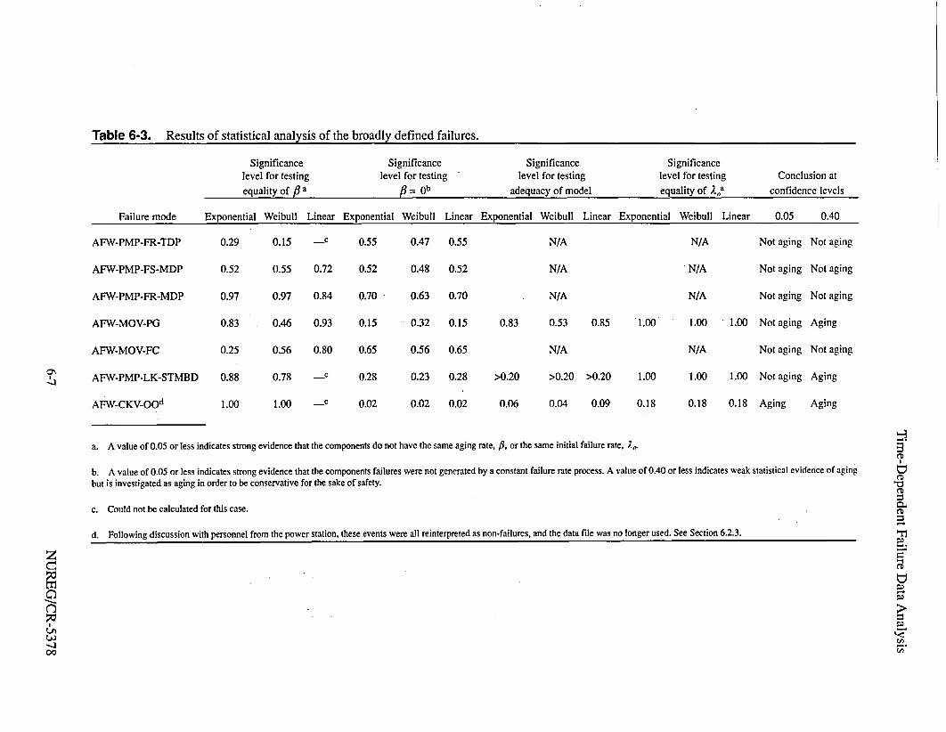
Table 6-3. Results of statistical analysis of the broadly defined failures.
Significance Significancelevel for testing level for testingequality of P. P = ob
Significance Significancelevel for testing level for testing
adequacy of model equality of AOaConclusion at
confidence levels
Failure mode Exponential Weibull Linear Exponential Weibull Linear Exponential Weibull Linear Exponential Weibull Linear 0.05 0.40
AFW-PMP-FR-TDP 0.29 0.15 C 0.55 0.47 0.55 N/A N/A Not aging Not aging
AFW-PMP-FS-MDP 0.52 0.55 0.72 0.52 0.48 0.52 N/A N/A Not aging Not aging
AFW-PMP-FR-MDP 0.97 0.97 0.84 0.70 0.63 0.70 N/A N/A Not aging Not aging
AFW-MOV-PG 0.83 0.46 0.93 0.15 0.32 0.15 0.83 0.53 0.85 1.00 1.00 1.00 Not aging Aging
AFW-MOV-FC 0.25 0.56 0.80 0.65 0.56 0.65 N/A N/A Not aging Not aging
(ON AFW-PMP-LK-STMBD 0.88 0.78 -c 0.28 0.23 0.28 >0.20 >0.20 >0.20 1.00 1.00 1.00 Not aging Aging
AFW-CKV-OOd 1.00 1.00 -c 0.02 0.02 0.02 0.06 0.04 0.09 0.18 0.18 0.18 Aging Aging
a. A value of 0.05 or less indicates strong evidence that the components do not have the same aging rate, P, or the same initial failure rate, A,
b. A value of 0.05 or less indicates strong evidence that the components failures were not generated by a constant failure rate process. A value of 0.40 or less indicates weak statistical evidence of agingbut is investigated as aging in order to be conservative for the sake of safety.
c. Could not be calculated for this case.
d. Following discussion with personnel from the power station, these events were all reinterpreted as non-failures, and the data file was no longer used. See Section 6.2.3.
z
C)
t.1
00
=i=10n
11:3n:3Q.n:3
171E.r-�1t�wP
;11 �k<
4 -Cn
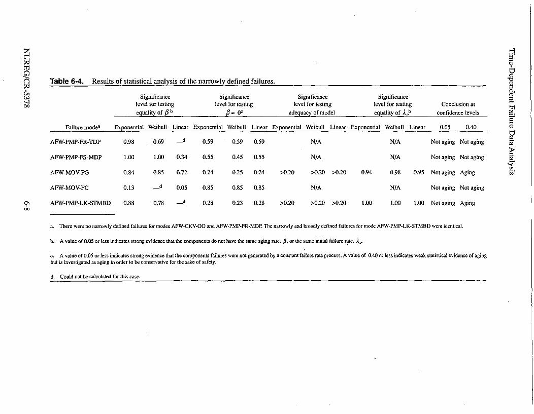
zc)rri
0
Po(!A
00
Table 6-4. Results of statistical analysis of the narrowly defined
Significance Significancelevel for testing level for testinequality of /3 b P = Oc
Significance Significanceg level for testing level for testing
adequacy of model equality of AobConclusion at
confidence levels
El
t:)
0a.
CD
Pz
1I-
_.
az
Failure modea Exponential Weibull Linear Exponential Weibull Linear Exponential Weibull Linear Exponential Weibull Linear 0.05 0.40
AFW-PMP-FR-TDP 0.98 0.69 _d 0.59 0.59 0.59 N/A N/A Not aging Not aging
AFW-PMP-FS-MDP 1.00 1.00 0.34 0.55 0.45 0.55 N/A N/A Not aging Not aging
AFW-MOV-PG 0.84 0.85 0.72 0.24 0.25 0.24 >0.20 >0.20 >0.20 0.94 0.98 0.95 Not aging Aging
AFW-MOV-FC 0.13 _ d 0.05 0.85 0.85 0.85 N/A N/A Not aging Not aging
AFW-PMP-LK-STMBD 0.88 0.78 _d 0.28 0.23 0.28 >0.20 >0.20 >0.20 1.00 1.00 1.00 Not aging Aging00
a. There were no narrowly defined failures for modes AFW-CKV-OO and AFW-PMP-FR-MDP. The narrowly and broadly defined failures for mode AFW-PMP-LK-STMBD were identical.
b. A vatue of 0.05 or less indicates strong evidence that the components do not have the same aging rate, P, or the same initial failure rate, A,
c. A value of 0.05 or less indicates strong evidence that the components failures were not generated by a constant failure rate process. A value of 0.40 or less indicates weak statistical evidence of agingbut is investigated as aging in order to be conservative for the sake of safety.
d. Could not be calculated for this case.

Time-Dependent Failure Data Analysis
models. In mathematical terms, they are not well-behaved. While this is inconvenient, it does notprevent the use of the models for other sets ofdata, and with the support of the exponentialmodel, does not necessarily prevent the furtherapplication of the Weibull and linear models. Forexample, even though the linear model was inca-pable of providing a result for the case of the nar-rowly defined, pump steam-binding failure, boththe exponential and Weibull models indicatedacceptance of the equality of the Ps. Therefore,the linear model continued to be applied to thiscase as though the set of components had shownequality using this model.
6.2.2 Aging Test. After the test for common fi,the next task was to test for statistically signifi-cant aging. The significance level of the nullhypothesis, fi = 0, was checked for all sets ofcomponents passing the first screening test.Recall that the null hypothesis assumed a homo-geneous Poisson process, implying constant fail-ure rate. The test for significance must identifyany statistically significant evidence to the con-trary. Therefore, evidence of an increasing rate offailure, assumed in this report to be aging, can bemodeled by a positive Pi.
The approach for analyzing data for the pres-ence of aging used two significance levels, 0.05and 0.40 (Section 2.5). Traditional statisticswould use only the 0.05 value for testing statisti-cal significance of aging. However, for a safetyanalysis it can be argued that the relaxation of thisconvention is conservative and, therefore, justi-fied. The result is that components are identifiedin which there is less confidence that the agingtrend is present. Frequently, these componentshave a large uncertainty, indicating the need formore data to make any confident statement on thefailure trends. The result of including componentsto the 0.40 significance level is that more aging,and thus more risk, is predicted than may actuallybe present. This is generally conservative and,therefore, acceptable.
The significance level values for fi 0 rangedfrom 0.85 to 0.02, as shown in Tables 6-3 and 6-4.One broadly defined failure set and no narrowly
defined failure sets exhibited significance levelsless than 0.05. The broadly defined failure set wasthe pump discharge header check valve backflowfailure (AFW-CKV-OO). After the check valvemaintenance records were reinterpreted, asdescribed below, no data sets showed aging at asignificance level less than 0.05. Two additionalsets exhibited aging at the 0.40 level of signifi-cance for both the broadly and narrowly definedfailures. These two sets were the 3-in. MOV plug-ging failure (AFW-MOV-PG) and pump steambinding failure (AFW-PMP-LK-STMBD).
6.2.3 Adequacy Check of the AssumedForm of the Aging Model. Initially the fivecomponent failure data sets that showed indica-tion of aging at either the 0.05 or 0.40 signifi-cance level were tested to see if any of the threeassumed model forms provided an adequatedescription of the data. As in the previous screen-ing, 0.05 was used to test the assumption(Section 5.3.2). The hypothesized model formwould be accepted if the failure times predictedby the model were close to the actual failuretimes. For all the data sets except one, the level ofsignificance ranged from 0.20 to 0.85, as shownin Tables 6-3 and 6-4. For backflow of the checkvalves, the significance level was from 0.04 to0.09, depending on the assumed model.
The Q-Q plots (Section 5.3.2) for the five datasets for each of the three models (shown in Fig-ures 6-2 to 6-13) are consistent with the signifi-cance levels shown in Tables 6-3 and 6-4. Theplots indicate that some clustering of dataoccurred, but except for backflow of the checkvalves, the plots show no gross deviations fromthe 45-degree line that represents perfect agree-ment between actual and predicted failure times.
For backflow of the check valves (failure modeAFW-CKV-OO), based on the broad definition offailures, clustering of the failure dates made thefit to any of the models marginal at best. The clus-tering of failure times is shown in the timeline(Figure 4-16), in the cumulative failure plot (Fig-ure 4-17), and in the corresponding Q-Q plots(Figures 6-2 through 6-4). Several possible*causes of this clustering were conjectured, but the
6-9 NUREG/CR-5378

Time-Dependent Failure Data Analysis
125.04I] 130.00
U,-o
CC)
U,0
s0
-o
C,
CO
coUCC
0
*
* a0*
--S
, S
S
58.13 L
L:1 I ""I I I 185.16 127.00
Actual hours to failure (thousands)0
S252 Sn-0890-27
Figure 6-2. Q-Q plot for pump discharge check valves, broadly defined back leakage failures, exponen-tial model, based on failures before the data were reinterpreted.
130.0025.04 _ -I
Li,
s'aaco
VD
._
0
2CC
0
is
_0
'0
U
* ,,..
. .
.I
I
*
63.98 L
0
I gill I I I85.16 127.00
Actual hours to failure (thousands) S252 SR-0890-28
Figure 6-3. Q-Q plot for pump discharge check valves, broadly defined back leakage failures, Weibullmodel, based on failures before the data were reinterpreted.
NUREG/CR-5378 6-10

124.41
Time-Dependent Failure Data Analysis
:130.00.0
0~~~ a
0 ~ ~ /
*0 ,.
*
*S..
e0
0R
C~C)
ID
co
V)
0
U)
0
.0
0,.Cl
IUnl
U-
62.87 L .
L: I III I I I0 85.16 127.00
Actual hours to failure (thousands)
Figure 6-4. Q-Q plot for pump discharge check valves, broadly defined backmodel, based on failures before the data were reinterpreted.
S252 SR-0690-29
leakage failures, linear
125.56
RU)CcoC)
0
._CD
I0
Co
0
.so
U0
, 0
/ 0..0/ 0
0,
_~~ ~ ~ . S
a .
_ S -~~~
0/
0 '
I"
.~1
Ai;
A] 130.00
0.
,.'*
15.36 L
L' L0 15.4
l I I 11 III till 111 It I I I II I Il8 122.53
Actual hours to failure (thousands) 5252 SR-0590-21
Figure 6-5. Q-Q plot for 3-in. MOVs (header isolation valves), broadly defined plugging failures,exponential model
6-11 NUREG/CR-5378

Time-Dependent Failure Data Analysis
125.11
U,
a,u,
0
a)D
0
WE
0
2
10
2
2
0
a,
Uc0
CD
;l 130.00
.o
. 0,e
I, Ia
, 0~~~~
#. '* ,.R'-
S
0 11-
I~~~~~~
0- a.16.71
1:." I I I I pi I Ill 11 i 11 1 I I I 1 111 110 15.48 122.53
Actual hours to failure (thousands) S252 SR-090-22
Figure 6-6. Q-Q plot for 3-in. MOVs (header isolation valves), broadly defined plugging failures,Weibull model.
125.50
U,_0C
0-!E
0
.C
;Aq 130.004.,
f,.
4S..
*IS..Y
S.1
i *,-.5
16.54r S~~~01
. '
L:'' L I I
O'S
.0
I M
.'0
..00
P
0 15.48111 I1I 111 I I I I1I I 1
122.53Actual hours to failure (thousands) S252 SR-O890-23
Figure 6-7. Q-Q plot for 3-in. MOVs (header isolation valves), broadly defined plugging failures, linearmodel.
NUREG/CR-5378 6-12

Time-Dependent Failure Data Analysis
122.89] 130.00
q,.
,. a
* 0
a
0 0
. a
C3COC
coV)
0._2
.2o
s
2
CO0
0 .
0 "
0 .
.- 'I
a39.29
E ~ ~ I 1 lI I i il I
0 21.92 121.02Actual hours to failure (thousands) S252 SR-0690-24
)-Q plot for 3-in. MOVs (header isolation valves), narrowly defined plugging failures,lel.
Figure 6-8. Cexponential mod
1;i 130.00
122.51
U,
-O
C
._U)
0
co
0PU)
a20
0C)
CO,C'O
U
,!,. .
, 0/0
0
*,0
0 1* '
,0* ,.
.''A
039.77
." I ii " f I I I i I I0 21.92 121.02
Actual hours to failure (thousands) S252 SR-069O-25
Figure 6-9. Q-Q plot for 3-in. MOVs (header isolation valves), narrowly defined plugging failures,
Weibull model.
6-13 NUREG/CR-5378

Time-Dependent Failure Data Analysis
122.67
CCu3V)
0
:2
:20
1)
U
Ad, 13 0.0 0
G., a
0
D ,0
. 0
0..'
0 ,.0
a
0 .
A
39.46 0
0 21.92 121.02Actual hours to failure (thousands) S252 SR-0690-26
Figure 6-10. Q-Q plot for 3-in. MOVs (header isolation valves), narrowly defined plugging failures,
linear model.
§1130.00
_ 108.41 -v)'aaco
ToV)
0
-:- 82.83 -
-C
Cu
0
. _m,
Mo
to
CU
Uo
S
. S
0 92.48,92.53Actual hours to failure (thousands) S252 SR-0G90-30
Figure 6-11. Q-Q plot for either broadly or narrowly defined pump steam binding failures, exponentialmodel.
NUREG/CR-5378 6-14

Time-Dependent Failure Data Analysis
. 130.00
0~~~~~~~~
U)C
0
is
2!
0
IU
coU-
110.24 -
87.67 -
I
C,,0 92.48,92.53
Actual hours to failure (thousands) S252 SR-0890-31
Figure 6-12. Q-Q plot for either broadly or narrowly defined pump steam binding failures, Weibullmodel.
-7i 130.00
110.09 rC~
CucoV) Lo 88.93
._i
0
CO
0co
U
Cu
.
E '.0 92.48.92.53
Actual hours to failure (thousands) S252 SR-0690-32
Figure 6-13. Q-Q plot for either broadly or narrowly defined pump steam binding failures, linear model.
6-15 NUREG/CR-5378

Time-Dependent Failure Data Analysis
true causes could not be established from theavailable maintenance records.
Because the lack of fit was at the borderlinebetween acceptance and rejection (at the 0.05 sig-nificance level), the data were analyzed based onthe assumed aging models. This decision wasinfluenced by two considerations:
* Modeling the failure rate as increasing isconservative.
* Failures that cluster are not specifically aproblem for aging models. They are a prob-lem for any data analysis that is typicallydone for a PRA. In particular, the usualanalysis assumes that the failures are inde-pendent with a constant failure rate; cluster-ing violates the independence assumption.Thus, the lack of fit is present whether thecheck valves are treated as aging or not.
If this failure mode had had little effect on therisk, the issue would have been dropped. How-ever, as discussed in Section 7, backflow of checkvalves turned out to be the dominant contributorto risk. Therefore, when review comments on adraft were received from personnel at the powerstation, we inquired specifically about the leakagefailures.
The inquiry revealed three nearly simultaneousrepairs of the pump discharge check valves atUnit 1 in May 1983 (see Figure 4-16 andTable 6-1). These repairs were made as aresponse to notification that leakage of checkvalves might be a generic, industry-wide prob-lem. Indeed, some leakage was found, but thetime of the onset of the leakage in each valve isunknown. The recurrent repairs of valve 2-CV-Cwere unsuccessful attempts to stop leakage thatcame from a different source, a failed orifice on arecirculation line, not through the check valve atall.
The most important discovery, however, wasthat none of the leakage events was severe enoughto cause failure mode AFW-CKV-OO, backflowthrough the pump discharge check valve. (Recallthat a maintenance record was classified as a fail-
ure under the broad definition if it was consideredto possibly describe a failure, although it mightonly describe a problem that was fixed before thecomponent had to be removed from service).Based on this additional knowledge, all the leak-age events were reclassified as non-failures forthe failure mode AFW-CKV-OO. The eventswere retained, however, for the steam bindingfailure mode (AFW-PMP-LK-STMBD) becauseminimal leakage is needed for that failure mode.
Therefore, the reinterpretation of the raw dataeliminated AFW-CKV-OO as a failure modeaffected by aging and left the calculations forAFW-PMP-LK-STMBD unchanged. After thereinterpretation, there was no problem with lackof fit to any of the aging models.
6.2.4 Common A, Test for All ComponentsExhibiting Aging. Next, the five componentfailure data sets that were determined to showtime-dependent trends were analyzed to test theadequacy of the assumption that the data shouldbe pooled based on equality of A, (Section 5.3.3).As for the equality test for A, if the significancelevel had been less than 0.05, then the signifi-cance levels and confidence interval plots asso-ciated with the component comparisons wouldhave been visually checked for indication of anoutlier, and engineering judgement would havebeen used to help decide whether to split the data.The assumption of pooling was found acceptablefor all five data sets at significance levels rangingfrom 0.18 to 1.00, as shown in Tables 6-3 and 6-4.The confidence interval plot for A, for the 3-in.MOV plugging failure is shown in Figure 5-6.
6.2.5 MLE for (/3A). The MLEs for j3 and A,were found for the five component failure datasets that passed the screening to this point (Sec-tion 5.3.5). The results are shown by data set andassumed model in Table 6-5.
6.2.6 Check of the Normal Approximationfor Distribution of MLE. The MLE is a pointestimate only. To get a confidence band for A(), itwas assumed that the MLE (#,'logA,) had abivariate normal distribution (Section 5.3.5). Thisassumption resulted in an approximately
NUREG/CR-5378 6-16

Table 6-5. MLEs for /3 and A, by aging model and failure definition.
Aa > b
Failure mode Exponential Weibullc Linearc Exponential Weibullc Linear'
AFW-MOV-PG
AFW-PMP-LK-STMBD
AFW-CKV-OOd
7.47E - 06
1.34E-05
2.34E -05
0.3
1.5(
2.3'
Broadly Defined Failures
12 7.66E-06
9 2.17E-05
7 2.17E-05
Narrowly Defined Failures
2.18E-05
1.16E -06
2.77E -06
3.97E-05
3.60E-06
1.96E-05
3.86E -05
3.76E -06
2.26E - 05
AFW-MOV-PG 9.07E-06 0.603 9.79E-06 7.92E-06 1.64E-05 1.60E - 05
AFW-PMP-LK-STMBD 1.34E -05 1.59 2.17E -05 1. 16E -06 3.6E -06 3.76E -06
a. Units are 1/hour under the exponential and linear models, and dimensionless under the Weibull model.
b. Units are 1/hour.
c. For the linear model the data were centered, that is, all times were measured from a point near the middle of the observation period (tmid. defined in Section 4.3of Appendix A.) For the Weibull model, the normalizing time t, was set equal to this same tmid.
d. Following discussion with personnel from the power station, the events with leakage of check valves were all reinterpreted as non-failures. and the failure modeAFW-CKV-OO was no longer regarded as affected by aging. See Section 6.2.3.
zC'
00

Time-Dependent Failure Data Analysis
lognormal distribution for A(t), which could thenbe used for PRA input. To check the adequacy ofthe bivariate normal assumption, a graphicalcomparison was made of the conservatively esti-mated confidence region and the confidenceregion based on the asymptotic normalityassumption. The comparisons are shown inFigures 5-8 through 5-11 for 3-in. MOVs (AFW-MOV-PG) with broadly defined failures and inFigures 6-14 to 6-21 for the other data sets. No
figure is shown for the linear model when id wasat the end of the allowed range; in those casesasymptotic normality did not hold. For all the fail-ure sets, the assumption of approximate normalityappeared good enough when the exponential orWeibull model was used. Approximate normalitywas clearly false with the linear model; muchlarger data sets would have been needed beforethe asymptotic normal distribution wasapproached.
For pump steam binding under the Weibullmodel (Figure 6-21), the confidence ellipse wastruncated at the minimum allowed value ofis = -1. This indicated that the normal approxi-mation was not very good. The difficulty does notaffect the upper bound for future A(t), however,and therefore was ignored.
6.3 Calculation of 2(t) as aFunction of Time
With the screening completed, the value of A(t)and its associated confidence interval were calcu-lated as a function of time for the five data sets
showing a time-dependent behavior (Sec-tion 5.3.5). The point estimate of A(t) was calcu-lated for all three models to allow comparison,but the confidence intervals were calculated foronly the exponential and Weibull models becauseof the failure of the asymptotic normalityassumption for the linear model. The results ofthe calculations are shown in Tables 6-6 to 6-8.
The year 1987 in these tables represents thevalue of A at the "present" time, the time at whichthe data collection ceased. The years 1988, 1989,and 1990 represent the "future" and show the pre-dicted value of A based on the demonstratedtrend. No values of A were calculated further inthe future because the unknown, but significant,effects of human interaction (mitigation) candrastically change the rate of aging.
6.4 Case Study ProblemSpecifications
The results of all raw failure data collection,development, and analysis were used in the calcu-lation of time-dependent plant risk. Numerouscases were analyzed in this work. Each case wasa combination of the definition of failure (broador narrow), the significance level at which theno-aging assumption was rejected (0.40 or 0.05),and the model employed (exponential, Weibull,or linear). Remember that only point estimateswere possible for the linear model because theconfidence interval on the MLE could not be cal-culated. The failure sets analyzed as a result of thedifferent combinations are shown in Table 6-9.
NUREG/CR-5378 6-18

Time-Dependent Failure Data Analysis
5.5E-5 -
4.5 E-5 -
3.5E-5
1. 2.5 E-5
1 .5E-5
5.0 E-6
-5.OE-6 _10-7
I I I I I. ,.. . .
2 3 4 2 3 4 2 31 0-6 1 0-5
Xo (1 /h)
Figure 6-14. 90% confidence regions for (fiA,,) for pump discharge check valves, broadly defined backleakage failures, exponential model, based on failures before the data were reinterpreted.
5.5 r
4.5
3.5
o- 2.5
1.5
0.5
-0.56 7 8 9 2 3 4
10-5Xo (1 /h)
Figure 6-15. 90% confidence regions for (f,B,) for pump discharge check valves, broadly defined backleakage failures, YWeibull model, based on failures before the data were reinterpreted.
6-19 NUREG/CR-5378

Time-Dependent Failure Data Analysis
3.0E-5
2.0E-5
1 .OE-5
O.OEO F
-1 .OE-5
-2.OE-52 3 4 5 6 2 3 4 5 6
10-6 10-5
Xo (1 /h)
Figure 6-16. 90% confidence regions for (PLAo) for 3-in. MOVs (header isolation valves), narrowlydefined plugging failures, exponential model.
2.0
1.5
1.0
a- 0.5
0.0
-0.5
-1.00.0 EO 5.OE-6 1.0E-5 1.5E-5
X0 (1/h)2.OE-5 2.5E-5 3.OE-5
Figure 6-17. 90% confidence regions for (,B) for 3-in. MOVs (header isolationdefined plugging failures, Weibull model.
valves), narrowly
NUREG/CR-5378 626-20

Time-Dependent Failure Data Analysis
2.5E-4
2.0E-4
1 .5E-4
- 1.OE-4
5.OE-5
O.OEO
-5.OE-5 I . . . . ..... . . ...
2 3 4 2 3 4 2 3 410-7 10-6 10-5
Xo (1 /h)
Figure 6-18. 90% confidence regions for (filo) for 3-in. MOVs (header isolation valves), narrowlydefined plugging failures, linear model, time measured from component's installation.
1.5E-5 r
1.OE-5 F
5.0E-6
O.OEO
-5.0E-6
-1 .OE-5
-1.5 E-5
-2.OE-5 I I I P7 8 9 2 3
I 0-5
Xo (1/h)
Figure 6-19. 90% confidence regions for (#,A,) for 3-in. MOVs (header isolation valves), narrowlydefined plugging failures, linear model, time measured from middle of observation periods.
6-21 NUREG/CR-5378
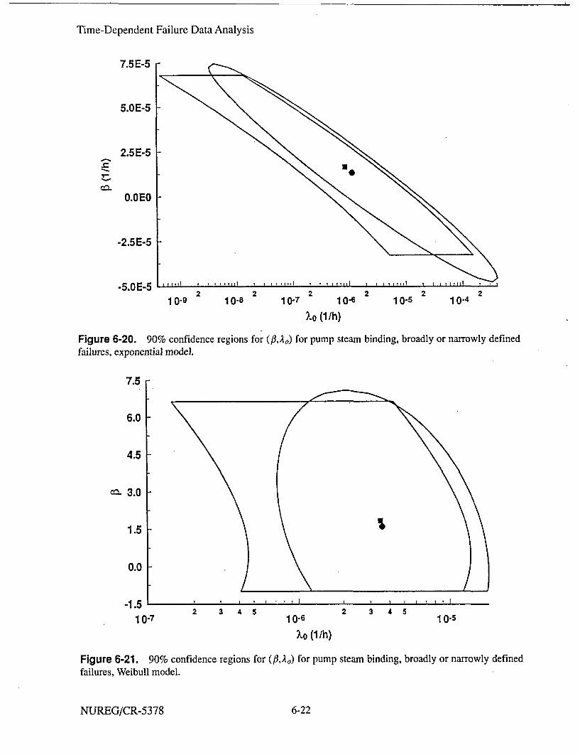
Time-Dependent Failure Data Analysis
7.5 E-5
5.0E-5
M
C-)
2.5E-5
O.OEO
-2.5 E-5 [-5.OE-5 '11111 I2 2 2 2 2 2
1 0-9 2 1 0-8 2 1 07 2 1 0-6 1 0-5 2 1 0-42
Xo (1/h)
Figure 6-20. 90% confidence regions for (MA,) for pump steam binding, broadly or narrowly definedfailures, exponential model.
7.5
6.0
4.5
<m 3.0
1.5
0.0 F
. . . . . . I-1.5 L1 0-'7
2 3 4 5 2 3 4 510-6
2,o (1/h)
1 0-5
Figure 6-21. 90% confidence regions for (f,A,) for pump steam binding, broadly or narrowly definedfailures, Weibull model.
NUREG/CR-5378 6-22

Table 6-6. MLEs of 1(t) and associated confidence intervals by failure mode definition for the exponential model.
A(t) and confidence interval
Failure mode 1987 1988 1989 1990
Broadly Defined Failures
AFW-MOV-PG
AFW-PMP-LK-STMBD
AFW-CKV-OOa
5.81E -053.50E-05 to 9.64E-05
6.70E - 067.66E-07 to 5.86E-05
6.20E-053.50E-05 to I.IOE-04
7.53E-066.03E -07 to 9.42E -05
7.08E-052.65E-05 to 1.89E-04
6.62E -053.50E-05
8.47E-064.67E-07
8.69E-052.77E -05
to I.26E-04
to 1.53E-04
to 2.72E-04
7.07E -053.48E-05
9.52E-063.59E-07
1.07E - 042.89E - 05
to I.44E-04
to 2.53E-04
to 3.94E-045.77E-052.52E-05 to 1.32E-04
Narrowly Defined Failures
AFW-MOV-PG
AFW-PMP-LK-STMBD
2.61E-051.20E-05 to 5.67E-05
6.70E -067.66E-07 to 5.86E-05
2.83E-05 3.06E-051.18E-05 to 6.80E-05 1.15E-05 to 8.18E-05
to 1.53E-04
3.32E-051.12E-05
9.52E -063.59E - 07
to 9.86E-05
to 2.53E-047.53E-066.03E-07 to 9.42E-05
8.47E-064.67E-07 la
a. Following discussion with personnel from the power station, the events with backflow of check valves were all reinterpreted as non-failures, and the failure mode
AFW-CKV-OO was no longer regarded as affected by aging. (See Section 6.2.3.) Therefore, A(t) was taken to be the constant value given in the NUREG- I150 PRA.
in
-o00

C.)
O~
00
Table 6-7. MLEs of A(t) and associated confidence intervals by failure mode definition for the Weibull model.
A(t) and confidence interval
Failure mode 1987 1988 1989 1990
-39'
00CD
C).O'
IIIE
C8t:�pp
EL,--e_
14.W
Broadly Defined Failures
AFW-MOV-PG
AFW-PMP-LK-STMBD
AFW-CKV-OOa
4.76E-053.21E-05
7.37E-061. 12E -06
5.68E-052.70E-05
to 7.07E-05
to 4.83E-05
to 1.20E-04
4.86E-053.20E-05 to 7.39E-05
8.17E -069.99E-07 to 6.67E-05
4.95E -053.18E-05
8.99E -068.87E-07
7.64E-052.97E -05
to 7.71E-05
to 9.12E-05
to 1.96E-04
5.04E-053.17E-05
9.85E-067.87E-07
8.75E-053.09E -05
to 8.03E-05
to 1.23E-04
to 2.47E-040"
6.62E -052.84E -05 to 1.54E-04
Narrowly Defined Failures
AFW-MOV-PG
AFW-PMP-LK-STMBD
2.34E -051.25E-05
7.37E-061. 12E - 06
to 4.40E -05
to 4.83E-05
2.34E-05AE-02.44E -051.24E-05
8.17E-069.99E -07
to 4.79E -05
to 6.67E-05
2.53E -051.23E-05
8.99E -068.87E -07
to 5.19E-05
to 9.12E-05
2.62E-051.22E-05
9.85E-067.87E-07
to 5.60E-05
to 1.23E-04
a. Following discussion with personnel from the power station, the events with backflow of check valves were all reinterpreted as non-failures, and the failure modeAFW-CKV-OO was no longer regarded as affected by aging (Section 6.2.3). Therefore, A(t) was taken to be the constant value given in the NUREG- 1150 PRA.
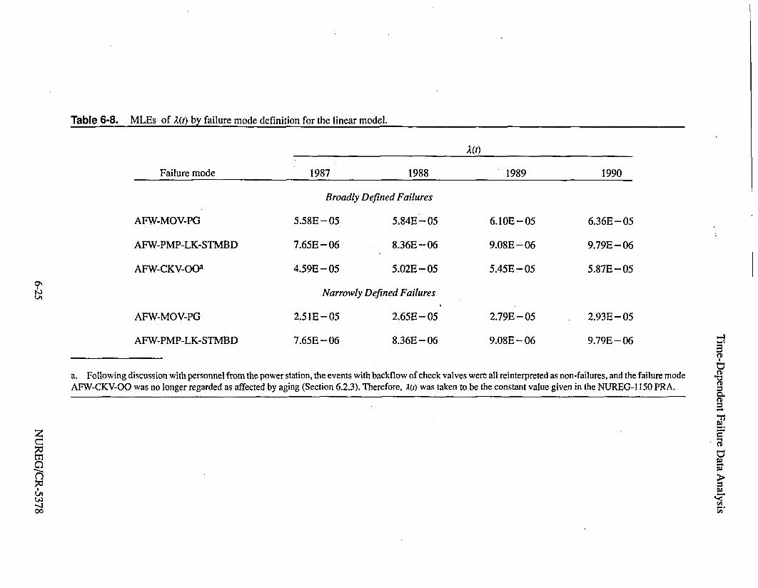
Table 6-8. MLEs of A(t) by failure mode definition for the linear model.
A(t)
Failure mode 1987 1988 1989 1990
AFW-MOV-PG
AFW-PMP-LK-STMBD
AFW-CKV-OOa
Broadly Defined Failures
5.58E-05 5.84E-05
7.65E-06 8.36E-06
4.59E-05 5.02E-05
Narrowly Defined Failures
6.10E-05
9.08E -06
5.45E-05
6.36E-05
9.79E -06
5.87E -050o%
tAj
AFW-MOV-PG 2.51 E-05 2.65E -05 2.79E -05 2.93E -05
AFW-PMP-LK-STMBD 7.65E -06 8.36E -06 9.08E -06 9.79E -06
a. Following discussion with personnel from the power station, the events with backflow of check valves were all reinterpreted as non-failures, and the failure modeAFW-CKV-OO was no longer regarded as affected by aging (Section 6.2.3). Therefore, A(r) was taken to be the constant value given in the NUREG-l 150 PRA.
O-q9'
t�CD
IC$0
-CLCD
ZI
E,. R0toW
P�4.LIn
z
00
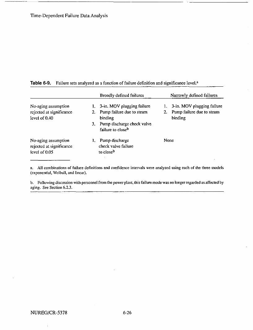
Time-Dependent Failure Data Analysis
Table 6-9. Failure sets analyzed as a function of failure definition and significance level.a
Broadly defined failures Narrowly defined failures
No-aging assumptionrejected at significancelevel of 0.40
1. 3-in. MOV plugging failure2. Pump failure due to steam
binding3. Pump discharge check valve
failure to closeb
1. 3-in. MOV plugging failure2. Pump failure due to steam
binding
No-aging assumptionrejected at significancelevel of 0.05
1. Pump dischargecheck valve failureto closeb
None
a. All combinations of failure definitions and confidence intervals were analyzed using each of the three models(exponential, Weibull, and linear).
b. Following discussion with personnel from the power plant, this failure mode was no longer regarded as affected byaging. See Section 6.2.3.
NUREG/CR-5378 6-26

7. QUANTIFICATION OF TIME-DEPENDENT RISK
7.1 Time-Dependent RiskAnalysis for AFW System
The final step in the risk quantification was thecalculation of CDF using a PRA model. The usualinputs to a PRA include the time-averaged failurerates for various failure modes. In order to calcu-late the time-dependent CDF associated with theaging of the AFW system, the time-dependentfailure rates developed in previous chapters weresubstituted for the time-averaged values.
7.1.1 Use of Maximum Likelihood Results toDefine Bayeslan Distributions. The work ofSection 6 resulted in point estimates and confi-dence intervals for A(t), the failure rate of a type ofcomponent at a specified time t. The MLE A(t)has a distribution that is approximately lognormal(Section 5.3.5). Plots were examined (Figures 5-8through 5-11 and 6-14 through 6-21) to ensurethat this lognormal approximation was acceptablewith our data. Use of the lognormal distributionthen yielded the approximate 90% confidencebands developed in Section 5 (Figure 5-12) andSection 6 (Tables 6-6 and 6-7).
The usual PRA techniques require a differentinput to the computer code, a Bayesian distribu-tion for A(r), The conversion from a confidenceinterval to a Bayesian distribution was accom-plished as follows. There is a Bayesian distribu-tion that results in intervals that are numericallythe same as the confidence intervals, but nowwith a Bayesian interpretation. That is, the 90%confidence interval equals a 90% interval givenby the Bayesian density, the 95% confidenceinterval equals a 95% Bayesian interval, and soforth. This perfect agreement occurs if the Baye-sian distribution is identical to the lognormal dis-tribution for the MLE. Therefore, the requiredBayesian distribution for A(t) for an aging compo-
nent was set equal to the distribution of A(t) calcu-lated by PHAZE.
The usual textbook development of a Bayesiandistribution assumes a prior distribution and
combines it with the data to yield a posteriordistribution. For a sample application, see Bieret al. (1990). By contrast, the approach of thisreport does not use a prior distribution at all. Oneimportant reason is the difficulty in obtainingwell-justified prior distributions for aging rates.For example, the widely cited TIRGALEX report(Levy et al. 1988, p. 2.19) presents aging rates,but states "it is the relative positioning of the com-ponents, not the absolute numerical values ...[that are] important." The Bayesian distributionsof the present report are based on the data alonebecause confidence intervals depend on the dataalone. The results are as if the prior distributionscorresponded to complete ignorance. This is aconservative approach, which has been advo-cated, for example, by Vaurio (1990).
7.1.2 Resulting Time-Dependent ComponentFailure Rate Inputs. The PRA model was solvedusing the IRRAS computer code (Russell et al.1989). For lognormal inputs, IRRAS requires amean failure rate and an error factor as failuremode inputs. This mean is somewhat larger thanthe median; the median is numerically equal tothe MLE calculated by PHAZE.
Table 7-1 is a summary of these means anderror factors by aging model, by failure defini-tion, and by failure mode. The values were calcu-lated for the time when data collection ceased in1987 and for the three years following. As men-tioned in Section 2.4, we do not recommendextending the aging rates further into the futurebecause human interactions are unpredictable,unless possible mitigating actions are explicitlymodeled.
For comparison, the time-dependent failurerates were also calculated for 1973 and 1974, assummarized in Table 7-1. The year 1973 is theinitial operation date and can be used to calculatethe initial CDF. The values are shown for one yearlater, 1974, to allow a useful comparison for theWeibull failure rate, because this rate is zero attime zero for any positive value of Pi. Also shownin Table 7-1 are the time-averaged failure rates
7-1 NUREG/CR-5378

Z
-.100
Table 7-1. Mean values of A(t) and associated error factora by failure definition and failure model.
A(t) and error factorFailurc
Failure mode model NUREG-1150 1973 1974 1987 1988 1989 1990
Broadly Defined Failure
AFW-MOV-PG
AFW-PMP-STMBD
AFW-CKV-OOd
Exponential
Weibull
Linear
Exponentiale
Weibull
Linear
Exponential
Weibull
Linear
Exponential
Weibull
Linear
Exponential
Weibull
Linear
2.40E-05 2.1 2.52E-05 1.9 6.09E-05 1.66
L.OE-07 3 N/Ab 2.50E-05 2.8 4.90E-05 1.48
1.70E-05 1.96E-05 5.58E-05
4.85E-05 89.7 2.91E-05 60.3 1.60E-05 8.74
2.5E-05 30 N/Ab 2.48E-05 69.4 1.42E-05 6.56
0.00 0.0 7.64E -06
5.88E-06 7.9 6.36E-06 6.6 6.55E-05 2.29
2.OE-06 3 N/Ab 5.17E-06 105 6.29E-05 2.11
0.00 0.00 4.59E -05
Narrowly Defined Failure
1.02E-05 3.2 1.05E-05 2.8 2.92E-05 2.17
I.OE-07 3 N/Ab 9.20E-06 7.0 2.52E-05 1.88
4.53E-06 5.91E-06 2.51E-05
4.85E-05 89.7 2.91E-05 60.3 1.60E-05 8.74
2.5E-05 30 N/Ab 2.48E-05 69.4 1.42E-05 6.56
0.00 0.00 7.64E-06
6.59E -05
5.02E-05
5.84E -05
2.44E -05
1.84E-05
8.36E -06
8.46E -05
7.55E-05
5.02E -05
3.26E -05
2.65E -05
2.65E -05
2.44E-05
1.84E-05
1.77 7.14E-05 1.89
1.52 5.14E-05 1.56
6.10E-05
12.50 3.99E-05 18.12
8.17 2.42E-05 10.14
9.08E -06
2.67 L.IIE-04 3.13
2.33 9.01E-05 2.57
5.45E -05
2.40 3.66E-05 2.67
1.97 2.78E -05 2.05
2.79E -05
12.50 3.99E-05 18.12
8.17 2.42E-05 10.14
7.76E-05 2.03
5.25E-05 1.59
6.36E -05
6.93E-05 26.52
3.21E-05 12.52
9.79E -06
1.46E-04 3.70
1.07E-04 2.83
5.87E -05
10aPa_n000
ElI?t:�CD,Fe0
CLCDZ1�
MC6P71
t'j
AFW-MOV-PG
AFW-PMP-STMBD
4.13E-05 2.97
2.91E-05 2.14
2.93E -05
6.93E-05 26.52
3.21E-05 12.52
9.79E -068.36E -06 9.08E -06
a. For the exponential and Weibull models, the mean and error factor are given. The mean is larger than the MLE calculated in Section 6. For the linear model, only the MLE is given, as explained inSection 6.3. The Weibull failure rate is undefined at time zero (1973). Units of X are 1/hour.
b. The Weibull failure rate is either zero or undefined at the beginning of the component's life.
c. While point estimates (MLEs) for X at time zero are always less than MLEs for X at one year, the mean value may be larger because of a larger uncertainty at time zero.
d. The values shown are based on failures before the data were reinterpreted. Following discussion with personnel from the power station, the events with backflow of check valves were all reinterpretedas non-failures, and the failure mode AFW-CKV-OO was no longer regarded as affected by aging. (See Section 6.2.3.) The constant failure rate from the NUREG-1150 PRA was used.

Quantification of Time-Dependent Risk
taken from the NUREG-I150 PRA (USNRC1989).
7.1.3 PRA Adjustment to Allow Time-Dependent Risk Quantification. The PRA, asloaded into IRRAS, was verified by regeneratingthe cutsets from the fault trees and event treesusing the same truncation values as used in theoriginal NUREG- 1150 analysis. The cutsetsgenerated by IRRAS matched those ofNUREG-1150.
Changes were made to the PRA, in addition tothe input, in order to account appropriately forthose components that were aging. The mostfundamental change was to include componentfailure modes that were exhibiting aging and hadbeen truncated from the time-averaged analysis.This change was accomplished by completelyreanalyzing the PRA using an extremely largevalue for the failure rate of the failure modesshowing aging: pump steam binding, 3-in. MOVplugging, and pump discharge check valve back-flow. The top cutsets were then regenerated. Theresulting cutsets included the originals andapproximately 1,000 additional cutsets. Note, theadditional 1,000 cutsets had been truncated fromthe original PRA because they made a negligiblecontribution. They were included in the age-dependent PRA because it was not known if theywould make a contribution. This was not a changein the conceptual fault tree, only a change ofdetail in the computation.
These cutsets were used to calculate risk as afunction of time by using the failure rates shownin Table 7-1. For example, in order to calculatethe predicted risk associated with the exponentialaging model in the year 1990 for the narrow defi-nition of failure at the 0.40 level of aging signifi-cance, the inputs for 3-in. MOV plugging wouldbe 7.76E-05 and 2.03, the inputs for pump steambinding would be set to 6.93E-05 and 26.52, andthe inputs for all other failure modes would be setto the time-averaged values from theNUREG- 1150 PRA.
7.1.4 Results. After the data were reinterpreted,as described in Section 6.2.3, the two failuremodes affected by aging were (a) 3-in. MOV
plugging failure and (b) pump failure from steambinding, as given in Tables 6-9 and 7-1. The fail-ure modes, though not the failure rates, were thesame under both the broad and narrow definitionsof failure. The aging was statistically significantat the 0.40 level, but not at the 0.05 level.
The calculated risks for the various cases areshown in Table 7-2. The risk is expressed as totalCDF. The associated uncertainties were cal-culated by IRRAS with standard simulationtechniques using Latin-Hypercube sampling.Remember that since the linear model was unableto produce a distribution, an uncertainty or amean for this model could not be produced.
Figure 7-1 is a graphical plot of the values fromTable 7-2 corresponding to the broad definition offailure. The figure shows the mean and 90% inter-val for the CDF, assuming the exponential orWeibull model. For the linear model, the figureshows only the point estimate of the CDF, basedon MLEs, because uncertainty intervals were notcalculated for the linear model. The calculatedCDF is shown for three years: the initial year ofcommercial operation, 1973; the following year,1974; and the year when data collection ceased,1987. The predicted CDF is shown for the threefollowing years, 1988 to 1990. Also shown is theCDF taken from the NUREG-1 150 PRA, a timeaveraged value.
The striking feature of Figure 7-1 is that the"aging" CDF is virtually constant, negligibly dif-ferent from the steady-state values of theNUREG-1150 PRA. The increases in the twocomponent failure rates have almost no effect onthe overall CDF. Although not shown, a figurebased on the narrow definition of failures wouldbe very similar to Figure 7-1.
This report is primarily a demonstration of anapproach, not a presentation of plant-specificresults. Therefore, it is worth dwelling on some ofthe intermediate steps that led to Figure 7-1. Ini-tially, pump discharge check valve failure-to-close was considered to exhibit statisticallysignificant aging, as shown in Tables 6-9 and 7- 1,when the broad definition of failure was used.
7-3 NUREG/CR-5378

znic-I
-Ij
Table 7-2. Mean values of CDF and associated uncertainties quantified after reinterpretation of raw data.
Mean value CDF (yrt ) and 90% intervalbSignificance
levela Failure model 1973 1974 1987 1988 1989 1990
Broadly Defined Failure
0.40 Exponential 4.09E - 05 4.09E-05 4.09E - 05 4.09E - 05 4.09E-05 4.09E - 05
6.55E-06to 1.18-04 6.55E-06to 1.18-04 6.55E-06to 1.18E-04 6.55E-06to 1.18E-04 6.55E-06to 1.18E-04 6.55E-06to 1.18E-04
Weibull N/A 4.09E-05 4.09E - 05 4.09E - 05 4.09E-05 4.09E-05
6.55E-06to 1.18E-04 6.55E-06to l.18E-04 6.55E-06to 1.18E-04 6.55E-06to 1.18E-04 6.55E-06to 1.18E-04
Linear 3.30E - 05 3.30E - 05 3.30E-05 3.30E - 05 3.30E-05 3.30E - 05
Narrowly Defined Failure
0.40 Exponential 4.09E-05 4.09E -05 4.09E -05 4.09E - 05 4.09E - 05 4.09E - 05
6.55E-06to 1.18-04 6.55E-06to 1.18E-04 6.55E-06to 1.18E-04 6.55E-06to 1.18E-04 6.55E-06to 1.18E-04 6.55E-06to 1.18E-04
Weibull N/A 4.09E - 05 4.09E - 05 4.09E - 05 4.09E - 05 4.09E - 05
6.55E-06to 1.18E-04 6.55E-06to 1.18E-04 6.55E-06to 1.18E-04 6.55E-06to 1.18E-04 6.55E-06to 1.18E-04
Linear 3.30E - 05 3.30E-05 3.30E - 05 3.30E - 05 3.30E-05 3.30E - 05
a. There were no failure modes that rejected the no-aging assumption at the 0.05 level of significance.
b. Uncertainties could not be calculated for the linear model; therefore, only point estimates are given.
-o
0
0

Quantification of Time-Dependent RiskU-3
c10-
a) -4
CD
0cG)
a)0)CD
EE 10
a)
0U
- Exponential-- * WeibullA Linear
-_____-- NUREG-1150 PRAtime-averaged base case
-- r il- i1-l- T-1--- I lTA,1
10,1973 19
iA~1
1987 1988 1989 1990,,
Year for which risk calculation is applicable S306 SR-0191-02
Figure 7-1. Calculated mean CDF and 90% interval after the data were reevaluated. Note that theWeibull failure rate is undefined at time zero (1973) and that for the linear model the MLEs are plottedbecause means could not be calculated.
Although the checks for fit of the model caststrong doubt on the assumption of independentfailures, the failure rate for this failure mode wastentatively modeled as increasing, pendingreceipt of further information about the eventsrecorded in the data base. This led to the data inTable 7-3 and Figure 7-2, in which the CDF ispredicted to increase by a factor of about 2 in17 years of plant operation. This increase resultsentirely from backflow of pump discharge checkvalves, which has a calculated failure rate ofabout 1 per year at the end of the time period.Such a failure rate is contrary to experience.
Although Figure 7-2 was eventually discardedin favor of Figure 7-1, the following observationsapply to both figures.
* The mean and 90% interval of the total CDFis essentially the same regardless of whetherthe exponential or the Weibull model isused.
* The point estimate of CDF produced by thelinear model is similar to the meancalculated using the other two models.
* The initial CDFs calculated from the time-dependent failure rates are consistent withthe CDF from the PRA.
7.1.5 Simultaneous Aging. Caution must beused in applying the approach to be sure the inter-action of the aging of components is considered.If the increase in CDF is calculated separately forthe aging of each component, the sum of thechange in CDF will underestimate the changewith all components aging simultaneously. Thisoccurs because the aging interaction will not beincluded. The concept can be demonstrated by asimple example of a two-component cutset withboth components aging. If pi and P2 are the initialfailure probabilities and Ap, and zip 2 are theincreases in failure probabilities from aging, thenthe increase in failure probability of the cutsetfrom aging calculated as the sum of the increase
7-5 NUREG/CR-5378

~Cl
-I100
Table 7-3. Mean values of CDF and associated uncertainties quantified before reinterpretation of raw data.
Mean value CDF (yrl) and 90% intervalbSignilicance
IcveP Failure model 1973 1974 1987 1988 1989 1990
Broadly Defined Failure
0.4(0 Exponential 3.97E-05 4.25E-05 6.64E-05 7.87E-05 7.92E-05 I.09E-04
6.79E-06 to 1.19-04 7.08E-06 to 1.43E-04 9.02E-06 to 2.37E-04 9.47E-06 to 2.47E-04 9.45E-06 to 2.55E-04 7.53E-06 to 3.19E-04
Weibull N/A 4.51E-05 7.02E - 05 7.17E-05 7.29E-05 7.70E - 05
6.31E-06 to 1.33E-04 9.14E-06 to 2.04E-04 9.81E-06 to 2.23E-04 9.81E-06 to 2.39E-04 9.85E-06 to 2.61E-04
Linear 3.22E-05 3.22E-05 5.21E-05 5.39E-05 5.58E - 05 5.75E - 05
0.05 Exponential 3.97E - 05 4.25E-05 6.64E-05 7.87E-05 7.92E - 05 1.09E - 04
6.79E-06to 1.19-04 7.08E-06to 1.43E-04 9.02E-06to2.37E-04 9.47E-06to2.47E-04 9.45E-06to2.55E-04 7.53E-06to3.19E-04
Weibull N/A 4.51E-05 7.02E-05 7.17E-05 7.29E-05 7.70E-05
6.3 1E-06 to 1.33E - 04 9.14E - 06 to 2.04E-04 9.81E - 06 to 2.23E-04 9.81E - 06 to 2.39E - 04 9.85E - 06 to 2.61E - 04
Linear 3.22E-05 3.22E-05 5.21E-05 5.39E-05 5.58E-05 5.75E-05
Narrowly Defined Failure
0.40 Exponential 4.09E - 05 4.09E-05 4.09E-05 4.09E-05 4.09E - 05 4.09E - 05
6.55E-06to 1.18-04 6.55E-06to 1.18E-04 6.55E-061to .18E-04 6.55E-06to 1.18E-04 6.55E-06to 1.18E-04 6.55E-06to 1.18E-04
Weibull N/A 4.09E - 05 4.09E - 05 4.09E - 05 4.09E - 05 4.09E - 05
6.55E-06to 1.18E-04 6.55E-06to 1.18E-04 6.55E-06to 1.18E-04 6.55E-06to 1.18E-04 6.55E-06to 1.18E-04
Linear 3.30E-05 3.30E-05 3.30E - 05 3.30E - 05 3.30E-05 3.30E - 05
a. There were no narrowly defined failures that rejected the no-aging assumption at the 0.05 level of significance.
b. Uncertainties could not be calculated for the linear model, therefore only point estimates are given.
to0
* O00
.
~0(b
0
CD
co3C:

Quantification of Time-Dependent Risk
10-3
U
r / VExponentialWeibullLinearNUREG-1150 PRAtime-averaged base case
C
a)
L..4i-
a)
co
Eco
_0C)
To
.-4
0-5
1-- -- - - - - =
I A
T
TtI
A
I A
ii -A-L- , -_i-- - - - - - - - - - -- - - - - - - - - - -
-6
i-l/TI_1*1973 19 1987 1988 1989 1990,,_
Year for which risk calculation is applicable S306 SR-0191-01
Figure 7-2. Calculated mean CDF and 90% interval before the data were reevaluated. Note that theWeibull failure rate is undefined at time zero (1973) and that for the linear model the MLEs are plottedbecause means could not be calculated.
in failure probabilities with the components agingseparately is
[PI(P2 + ziP2) - PIP2]
+ [(pa + AP )P2 - PIP2]
P 1AP2 + P2aPI (7-1)
However, the change in failure probability cal-culated with the components aging simulta-neously is
[(KP + Ap0(p2 + 4P2)] - PIP21
aging interactions will be important. Therefore,to accurately calculate the increase in CDF whenthe aging interactions are important, the increasein failure probabilities for all aging componentsshould be included simultaneously in the PRA.
An objective of the research for this projectwas to demonstrate the approach by calculatingthe increase in CDF from the aging of compo-nents in a single system. Therefore, the demon-stration in this section calculates the CDF if onlythe AFW system ages. For the demonstrationcase, only a few components were shown to beaging. Increases in failure probabilities of thesecomponents were input simultaneously and theirmutual interactions were included. However, theterms for the interaction of aging with the agingof components in other systems were notincluded, and therefore, the effects of the interac-tion were not evaluated for the demonstrationstudy.
The above reasoning may also be applied tosystems rather than components. Of thesequences leading to core damage and involving
= P1AP2 + p24pI + ap 1Ap 2 (7-2)
Obviously, the calculation with the compo-nents aging separately does not include the inter-action term Ap,1Ap2. Of course, for cutsets withmore components there will be more interactionterms that are not included. If the increases infailure probabilities from aging are small, theaging interactions will be products of small num-bers and will not be significant. However, if theincreases in failure probabilities from aging arecomparable to those of the retained cutsets, the
7-7 NUREG/CR-5378

Quantification of Time-Dependent Risk
the AFW system, the vast majority involve simul-taneous unavailability of the AFW system andother safety systems. Simultaneous unavailabilityof two systems corresponds to a "system-levelcutset," in contrast to the usual component-levelcutset. Equations (7-1) and (7-2) can be appliedto the system-level cutsets by letting p denote theprobability that a system in unavailable, and let-ting Ap be the change in this probability thatresults from aging. Although we argued abovethat everything should be treated as aging simul-taneously, this report considered aging in onlyone system, the AFW system. However, the cal-culated effect of AFW aging was very small; inEquation (7-1), PothersAPAFW is very small, sozPAFIV must be small. Therefore, either APothersis small, in which case the interaction term is verysmall, or APothers is moderate or large, in whichcase the interaction term is much less than thenoninteraction term PAFIVAPothers. In either case,the calculated aging of the AFW system wouldhave little effect on CDF, even if all the systems inthe plant were treated as aging simultaneously.
In summary, an aging analysis normallyrequires simultaneous consideration of aging ofall components in all systems. In this particularcase, when only aging in the AFW system wasconsidered, the effect on CDF was extremelysmall. This shows that, even if aging of other sys-tems were considered simultaneously, the interac-tion terms would be small and aging of the AFWsystem would have a very small effect. If theeffect of aging of the one system had not been sosmall, it would have been necessary to considersimultaneous aging of the other systems as well.
7.2 Potential Applications
7.2.1 Extrapolation to Distant Future. The riskquantification approach presented in the preced-
ing section has not accounted explicitly for miti-gating or corrective actions. Therefore, asdiscussed in Section 2.4, the methodology pres-ented here is only useful for predicting risk for afew years in the future. Maintenance and replace-ment are treated implicitly as part of the environ-ment for observed past failures and, therefore,also for extrapolations to the future. Schemesmay be developed for future applications, such asthe use of periodic replacement intervals to resetthe time-dependent failure rate to the time-zerovalue (see Vesely et al. 1990) and/or the use ofcomponent replacement when the failure ratereaches a predetermined maximum allowed level.
7.2.2 Periodic Risk-Based Management.Another option is to apply the approach on a yearlybasis. This results in current risk knowledge witha small expenditure of effort. If such an analysisshows that the present or near-future calculatedCDF is substantially greater than the time-aver-aged CDF from the PRA, the components or sys-tems causing the increase should be identified.These components or systems could then be con-sidered for increased surveillance, maintenance,and/or engineering analysis.
This approach was applied to the AFW data ofthis study for the years 1979 through 1987. Foreach year, only the data available at that timewere analyzed. For example, the 1982 analysisused the data from 1978 through 1982. Theseanalyses, based on the narrow definition of fail-ure, showed possible aging problems in three ofthe years. None of these problems persisted yearafter year. This observation indicates that either(a) the trends identified were not actually present,but were false alarms, or (b) the maintenance pro-grams in place for the AFW system successfullydetected and mitigated the significant aging thatwas occurring.
NUREG/CR-5378 7-8

8. CONCLUSIONS
The objectives of this study were as follows:
* Develop a way to identify and quantify age-dependent failure rates of active compo-nents and to incorporate them into PRA.
* Demonstrate this approach by applyingit, with plant-specific data, to a fluid-mechanical system using the key elementsof a NUREG-1150 PRA.
* Present it as a step-by-step approach, so thatothers can use it for evaluating the signifi-cance of risk from aging phenomena in sys-tems of interest.
These objectives have been met. Several con-clusions of importance are as follows.
* A step-by-step approach has been devel-oped and demonstrated, which provides aworkable way to estimate present and near-term future risk based on the modelingassumptions.
* Aging in the AFW system at the analyzedplant has a negligible effect on plant CDFwhen aging of only the AFW system isassumed; however, with this assumption theinteraction with aged components in othersystems is not evaluated.
* Three aging models were considered: theexponential, Weibull, and linear failure ratemodels. With the data used, they producedvery similar results at times during the dataobservation period and for extrapolations afew years into the future. However, theexponential model clearly behaved best forquantifying uncertainties, and the linearmodel clearly behaved worst, being in someways unusable.
* The availability of statistical diagnostictools encourages the analyst to check thevalidity of the modeling assumptions. Inthis demonstration, these routine checksidentified clustering in one data set with
12 failures, necessitating a follow-upinvestigation. The other assumptions thatwere checked appeared acceptable in thisdemonstration.
We note the following difficulties in applyingthe approach. These observations are not surpris-ing to people experienced in risk assessment.
* Aging cannot be detected without high-quality data covering a substantial timeperiod. Ten years of data from the AFWsystem at two units provided minimalinformation, so that for many failure modesthe degree of aging could not be estimatedwith precision.
* The data of this report are likely to representa large plant-specific sample of failureevents for the period of time examined.Other standby safety systems have beenfound to exhibit very few failures in a simi-lar period of time (for example, Bier et al.1990).
* Classification of failure data from oldrecords is difficult. In this report, the prob-lem was addressed by using broad and nar-row definitions of failure. Judgment wasalso necessary in combining maintenancerecords that referred to the same event. Inone case, inquiry at the power stationresulted in a major reinterpretation of themaintenance records and a substantialchange in the calculated CDF.
* Failures tend to cluster in time. In one casethis cast strong doubt on the assumption ofindependent failures. In this demonstration,the difficulty was resolved by better inter-pretation of the raw maintenance reports. Inother cases, it might be necessary to developa model that does not assume independence.
* The maintenance and operational environ-ment may have changed at times in theplant's history, resulting in permanentimpact on trends. For example, it is possible
8-l NUREG/CR-5378

Conclusions
that certain early failure mechanisms havebeen eliminated. Any such changes couldnot be determined from the maintenancerecords alone; they may, however, influencethe estimated trend in the failure rate. Thedesire for data covering a substantial timeperiod, mentioned above, conflicts with thefact that operational practices change overtime.
To help interpret the maintenance records cor-rectly, it is useful to have input from peopledirectly familiar with the plant equipment, prac-tices, and history. This partially removes some ofthe above difficulties, although others areinherent in any effort to detect and quantify aging.
We also make the following observations con-cerning the possible application of themethodology.
* Extrapolation of observed trends to the dis-tant future would require more explicitincorporation of maintenance and replace-ment policies. They are treated implicitlyhere, as part of the environment for theobserved past failure events. Therefore, theapproach of this report should not be usedfor distant extrapolation.
* Periodic use of the approach at a plant issuggested as a means of supporting risk-based prioritization of surveillance, main-tenance, and engineering analysis efforts.
For managers who must make decisions basedon three models, two definitions of failure, andtwo significance levels, we, the authors of thisreport, offer the following suggestions. Use theexponential failure model. When aging of a com-ponent results in a significant increase in CDF,use a table similar to the following example.
Table 8-1. Example decision matrix.
Broadly defined failures Narrowly defined failures
No-aging assumptionrejected at significancelevel of 0.40
No-aging assumptionrejected at significancelevel of 0.05
Awareness.Inform operations andmaintenance staffs ofpotential problem.Reanalyze if failurespersist.
Strong interest.Investigate immediately todetermine whichmaintenance recordsdescribe actual failures ofconcern.
Strong interest.Inform operations andmaintenance staffs ofpotential problem.Reanalyze after shortperiod of time.
Very strong interest.Investigate immediatelyand determine whatmitigating action should betaken.
NUREG/CR-5378 8-2

9. REFERENCES
Alt, F. B., 1982, "Bonferroni Inequalities and Intervals," Encyclopedia of Statistical Sciences, Vol. 1,S. Kotz and N. L. Johnson (eds.), New York: John Wiley & Sons.
Atwood, Corwin L., 1990, User's Guide to PHAZE, a Computer Program for Parametric Hazard FunctionEstimation, EGG-SSRE-9017.
Atwood, Corwin L., 1992, "Parametric Estimation of Time-Dependent Failure Rates for Probabilistic RiskAssessment," Reliability Engineering and System Safety, 37, pp.1 81- 19 4 .
Bartholomew, D. J., 1955, Discussion of article by D. R. Cox, Journal of the Royal Statistical Society, SeriesB, 17, pp. 162-163.
Bier, V. M., D. C. Bley, Y.-M. Hou, D. H. Johnson, S. Kaplan, and J. E. Williamson, 1990, Development andDemonstration of Methods for Nuclear Power Plant Aging Risk Analysis: Bayesian Data Analysis,EGG-SSRE-8990, PLG-0743.
Cox, D. R. and P. A. W. Lewis, 1966, The Statistical Analysis of Series of Events, Section 3.3, London:Chapman and Hall.
Crow, Larry H., 1974, "Reliability Analysis for Complex, Repairable Systems," in Reliability and Biome-try: Statistical Analysis of Lifelength, F. Proschan and R. J. Serfling (eds.), Philadelphia: SIAM,pp. 370-410.
Crow, Larry H., 1982, "Confidence Interval Procedures for the Weibull Process with Applications to Reli-ability Growth," Technometrics, 24, pp. 67-72.
Donelson, III, John, 1975, Duane's Reliability Growth Model as a Nonhomogeneous Poisson Process,P-1162, Arlington, VA: Institute for Defense Analysis, December.
Engelhardt, Max, 1988, "Weibull Processes," Encyclopedia of Statistical Sciences, Vol. 9, S. Kotz andN. L. Johnson (eds.), New York: John Wiley & Sons.
Ghahramani, K., 1989, "PRA Data Base Development: An Integrated Approach," Proceedings of theInternational Topical Meeting on Probability, Reliability and Safety Assessment, Volume 2, April 2-7,Pittsburgh, Pennsylvania, pp. 882-891.
Hahn, G. J. and W. Q. Meeker, Jr., 1982, "Pitfalls and Practical Considerations in Product Life Analy-sis-Part I: Basic Concepts and Dangers of Extrapolation," Journal of Quality Technology, 14, pp. 144-152.
Levy, I. S., J. Wreatherall, G. DeMoss, A. Wolford, E. P. Collins, and D. B. Jarrell, 1988, Prioritization ofTIRGALEX-Recommended Components for Further Aging Research, NUREG/CR-5248, PNL-670 1.
Phillips, J. H., W. S. Roesener, H. L. Magleby, and V. Geidl, 1990, "Aging Risk of Passive Components,Status of the Project," 18th NRC Water Reactor Information Meeting, Rockville, MD, October 22-24.
Russell, Kenneth D. and Martin B. Sattison, 1989, Integrated Reliability andRiskAnalysis System (IRRAS),Version 2.0 User's Guide, NUREG/CR-5111.
Salvia, Anthony A., 1980, "Maximum Likelihood Estimation of Linear Failure Rate," IEEE Transactionson Reliability, R-29, pp. 49-50.
9-1 NUREG/CR-5378

References
Snee, Ronald D. and Charles G. Pfeifer, 1983, "Graphical Representation of Data," Encyclopedia of Statisti-cal Sciences, Vol. 3, S. Kotz and N. L. Johnson (eds.), New York: John Wiley & Sons.
USNRC, 1987, Nuclear Plant Aging Research (NPAR) Program Plan, NUREG- 1144, Revision 1.
USNRC, 1989, Severe Accident Risk Assessment for Five U.S. Nuclear Power Plants, NUREG-1 150,Draft 2.
Vaurio, J. K., 1990, "On the Meaning of Probability and Frequency," Reliability Engineering and SystemSafety, 28, pp. 121-130.
Vesely, William E., 1987, Risk Evaluations of Aging Phenomena: The Linear Aging Reliability Model andIts Extensions, NUREG/CR-4769, EGG-2476.
Vesely, W. E., R. E. Kurth, and S. M. Scalzo, 1990, Evaluation of Core Melt Frequency Effects Due toComponent Aging and Maintenance, NUREG/CR-55 10.
NUREG/CR-5378 9-2

Appendix A
Estimating Hazard Functionsfor Repairable Components
A-1 NUREG/CR-5378
The pages printed here as Appendix A have been issued as a separate EG&G Idaho report. They are reproduced here
with page numbers changed to make them more accessible to readers of this NUREG.
NUREG/CR-5378 A-2

EGG-SSRE-8972
ESTIMATING HAZARD FUNCTIONSFOR REPAIRABLE COMPONENTS
Corwin L. Atwood
Published May 1990
Idaho National Engineering Laboratory
EG&G Idaho
Idaho Falls, ID 83415-3421
Prepared for the
U.S. Nuclear Regulatory Commission
Washington, D.C. 20555
Under DOE Contract No. DE-AC07-761DO1570
A-3

ABSTRACT
This is a tutorial report, applying known formulas and tools in a way suitable for risk
assessment. A parametric form is assumed for the hazard function of a set of identical components.
The parameters are estimated, based on sequences of failure times when the components are restored to
service (made as good as old) immediately after each failure. In certain circumstances, the failure
counts are ancillary for the parameter that determines the shape of the hazard function; this suggests
natural tools for diagnostic checks involving the individual parameters. General formulas are given for
maximum likelihood estimators and approximate confidence regions for the parameters, yielding a confi-
dence band for the hazard function. The results are applied to models where the hazard function, is of
linear, exponential, or Weibull form, and an example analysis of real data is presented.
KEY WORDS: Time-dependent failure rate, Non-homogeneous Poisson process, Poisson intensity,
Exponential distribution, Exponential failure rate, Linear failure rate, Weibull distribution.
FIN No. A6389-Aging Components and Systems IV:
Risk Evaluation and Aging Phenomena
A-4

SUMMARY
This tutorial report presents a parametric framework for performing statistical inference on a
hazard function, based on repairable data such as might be obtained from field experience rather than
laboratory tests. This framework encompasses many possible forms for the hazard function, three of
which are considered in some detail. The theory is neatest and the asymptotic approximations most
successful when the hazard function has the form of a density in the exponential family. The results
presented include formulas for maximum likelihood estimates (MLEs), tests and confidence regions,
and asymptotic distributions. The confidence regions for the parameters are then translated into a
confidence band for the hazard function. For the three examples considered in detail, a table gives all
the building blocks needed to program the formulas on a computer; this table includes asymptotic
approximations when they are necessary to maintain numerical accuracy. Diagnostic checks on the
model assumptions are sketched.
The report gives an example analysis of real data. In this example, the methods are unable to
discriminate among an exponential hazard function, a linear hazard function, and a Weibull hazard
function. The MLE for the two parameters appears to have approximately a bivariate normal distribu-
tion under the exponential or Weibull hazard model, but not under the linear hazard model. If the
analysis using approximate normality is carried out in any case, the results appear similar for all three
models. If some model is preferred for theoretical or other reasons, the framework of this report
indicates a way to use it.
A-5

ACKNOWLEDGMENTS
I am grateful to my colleagues Andrew J. Wolford and W. Scott Roesener for the stimulus andinsights provided during the course of this work. I also thank Max Engelhardt for pointing out earlyrelated papers.
A-6
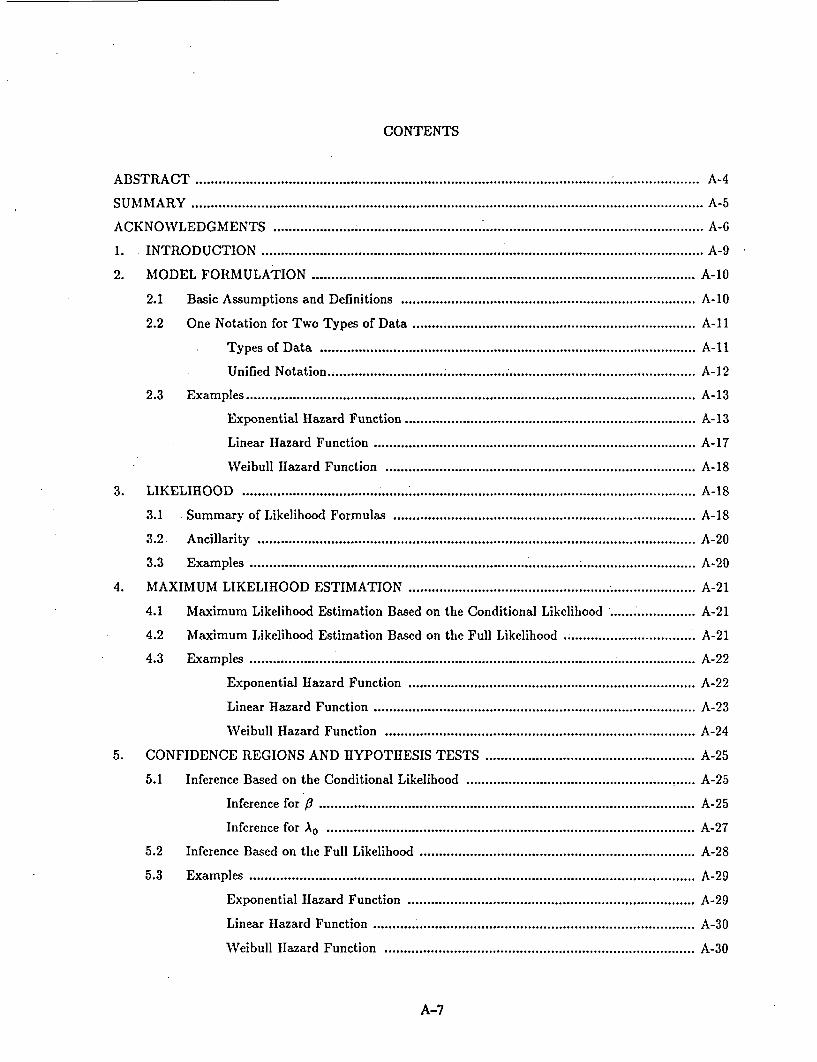
CONTENTS
ABSTRACT ........................................................................................................... ...................... A-4
SUMMARY ... A-5
ACKNOWLEDGMENTS ................. .. A-6
1. INTRODUCTION ................................. A-9
2. MODEL FORMULATION ................................. A-10
2.1 Basic Assumptions and Definitions ................ ...................................... A-10
2.2 One Notation for Two Types of Data .................. .................................... A-11
Types of Data ...................................................... A-11
Unified Notation ...................................................... A-12
2.3 Examples ...................................................... A-13
Exponential Hazard Function ...................................................... A-13
Linear Hazard Function ...................................................... A-17
Weibull Hazard Function ............. ......................................... A-18
3. LIKELIHOOD................. ................. A-18
3.1 Summary of Likelihood Formulas ................................ A-18
3.2 Ancillarity ................................ A-20
3.3 Examples ................................ A-20
4. MAXIMUM LIKELIHOOD ESTIMATION ............. .. ................. A-21
4.1 Maximum Likelihood Estimation Based on the Conditional Likelihood .......... ............ A-21
4.2 Maximum Likelihood Estimation Based on the Full Likelihood ................ .................. A-21
4.3 Examples ...................................................... A-22
Exponential Hazard Function ................. ..................................... A-22
Linear Hazard Function ...................................................... A-23
Weibull Hazard Function .............. ........................................ A-24
5. CONFIDENCE REGIONS AND HYPOTHESIS TESTS .......................................... A-25
5.1 Inference Based on the Conditional Likelihood ......... ......................... A-25
Inference for , .................................. A-25
Inference for AO .................................. A-27
5.2 Inference Based on the Full Likelihood .................................. A-28
5.3 Examples .................................. A-29
Exponential Hazard Function .................................. A-29
Linear Hazard Function .................................. A-30
Weibull Hazard Function .................................. A-30
A-7

6. DIAGNOSTIC CHECKS .............................................................. A-31
6.1 Common , .............................................................. A-31
6.2 Common AO .............................................................. A-31
6.3 Form of h(t) ............................................................... A-32
6.4 Adequacy of Asymptotic Normal Approximation ........................................................ A-33
7. EXAMPLE DATA ANALYSIS............................................................................................. A-34
8. DERIVATIONS AND PROOFS .............................................................. A-40
8.1 Derivation for Time-Censored Data ............................. ................................. A-42
The Likelihood .............................................................. A-42
Ancillarity ............................................................... A-42
8.2 Derivation for Failure-Censored Data ..................................... ......................... A-439. REFERENCES .............................................................. A-45
TABLES
1. Formulas for examples considered .............................................................. A-142. Summary of example data .............................................................. A-35
FIGURES
1. Component Comparisons for fi, Exponential Hazard Model ................................................. A-35
2. Q-Q Plot for Exponential Hazard Model ............................ .................................. A-37
3. Confidence Regions for (i3, AO), Based on Exponential Hazard Model ............. ...................... A-384. Confidence Regions for (,8, A0), Based on Linear Hazard Model, Centered Data ..... .............. A-38
5. Confidence Regions for (fl, AO), Based on Weibull Hazard Model ......................................... A-396. Confidence Regions for (,6, AO), Based on Linear Hazard Model, Uncentered Data ... ............. A-39
7. MLE and 90% Confidence Band for A(t), Based on Three Models ................. ........................ A-41
A-8

ESTIMATING HAZARD FUNCTIONSFOR REPAIRABLE COMPONENTS
1. INTRODUCTION
This report is concerned with the failure behavior of components. It is a tutorial report,
applying previously known results in a way suitable for risk assessment. The model is defined in terms
of the random variable T, the (first) failure time of a component. In many published articles, it is
assumed that many components are tested until their first failure. The resulting failure times are used
as data, and the properties of the distribution of T are then inferred. By contrast, this report deals
with field data, not test data: it is assumed that each failed component is immediately restored to
operability (made as good as old) and again placed in service. The data then consist of a sequence of
failure times for each component.
A question of interest is whether the hazard function (or failure rate) is increasing, that is,
whether the failures tend to occur more frequently as time goes on. This and related questions are
investigated by postulating a parametric form for the distribution of T, and then performing the usual
statistical inference about the parameters of the model, with special emphasis on the parameter(s) that
determine whether the hazard function is increasing. The final goals of the inference are a point
estimate and a confidence interval for the hazard function at any time t.
The general methods are applied in detail to three assumed parametric forms for the hazard
function. A table gives all the formulas needed to implement the methods on a computer for these
three models.
The outline of the report is as follows. Section 2 presents the assumptions and notation, and
introduces three examples. Sections 3, 4, and 5 develop the likelihood formulas and equations for
maximum likelihood estimators and tests/confidence intervals. Each of these three sections also
discusses the application of the general results to the three examples. People who can appreciate theory
without considering examples may skip the application portions. Section 6 outlines diagnostic checks,
A-9

and Section 7 presents an analysis of data from motor-operated valves. Proofs arc in Section 8.
2. MODEL FORMULATION
2.1 Basic Assumptions and Definitions
Assume that the failures of a component follow a time-dependent (or non-homogeneous)
Poisson process. See, for example, Karr (1986) for a simple description, or Cox and Isham (1980) for a
fuller introductory treatment. Alternatively, one can parallel the development from fundamental
assumptions as given by Meyer (1970, Section 8.3) for the homogeneous case. The most important
properties are the following: there is a nonnegative function A(t) defined for i > 0, with the
probability of a failure in a short period (1, I + At) asymptotically approaching A(t)At as At - 0; the
failure counts in non-overlapping time intervals are independent; and the number of failures occurring
between 0 and t is a Poisson random variable with parameter A(t), where
A t) Jt A(u) du
Implicit in the independence property is the assumption that the component is restored to
service immediately after any failure, with negligible repair time. In operational data, it is not
uncommon to find that a component has failed several times in quick succession for the same reason.
Presumably. the first repairs did not treat the true cause of the failure. This situation violates the
independence property-the fact that a failure has occurred recently increases the chance that another
failure will occur soon, because the problem may not have been really fixed. It may be difficult to
force such data into the Poisson-process model: counting the failures as distinct ignores their apparent
dependence, while counting them as a single failure may make the time to true repair far from negli-
gible.
The function A is called the hazard function, the failure rate, or the intensity function of the
Poisson process, and A is the cumulative hazard function. Assume now that A is continuous in I. It is
related to the cumulative distribution function (c.d.f.) F of the time to first failure, and to the
corresponding density function f by
A(i) = JRt)l[l- F(t)]
and
1 - F(1) = exp[-A(tl)]
A-10

Any one of the three functions F, f, and A uniquely determines the others. Note that because F(t) _ 1
as t - oo, it follows that
lim A(t) = oo . (1)
If A(t) is constant, as has been assumed for simplicity in many studies, the time to first failure
has an exponential distribution. Often the concern is whether A(t) is increasing in L. It is therefore
convenient to write A in the form
A(1) = Aoh(i;#). (2)
Here, A0 > 0 is a constant multiplier and h(t; P) determines the shape of A(t).
Because data generally come from more than one component, the following additional assump-
tions are made. The failures of one component are assumed to be independent of those of another
component. All the components are assumed to have the same function h with the same value of /3;
that is, a proportional hazards model is assumed. Depending on the context, it may or may not be
assumed that the different components have the same value of A0. Some simple regularity conditions
on h, needed for asymptotic results, are discussed at the beginning of the section on confidence intervals
and tests.
Sometimes there are gaps in the failure data. For example, the plant may have been shut
down for an extended period, during which no component failures were possible, or the failure data
may not have been collected for some period. This can be accommodated in the above framework by
treating each component as two components, one observed before the gap and one after the gap, having
the same installation date and, at the analyst's discretion, the same or possibly different values of A0.
2.2 One Notation for Two Types of Data
Types of Data
Failure data for a component can arise in a number of ways. Two simple ones to analyze are:
* A random number of failures in a fixed observation period (time-censored data)
* A fixed number of failures in a random observation period (failure-censored data).
The terms "time-censored" and 'failure-censored" follow the analogous usage for tests that are termina-
ted before all the items have failed (e.g. Nelson, 1982, Sec. 7.1). Time-censored data arise if there is a
A-11

fixed time period when the component is watched or plant records are examined. During that time,
the component is restored to service after each failure. Failure-censored data might arise if the
component is repaired until a predetermined number of failures has occurred, at which time the compo-
nent is removed from service and replaced by a new component. Both of these types of data result in
tractable formulas for statistical inference.
In reality, the decision to repair or replace a component is based on a number of considera-
tions, such as the availability of replacement components, the severity of the particular failure mode
(including the difficulty and cost of repair), and any recent history of failures. These considerations are
difficult to express in a simple mathematical model. Therefore, only the two types listed are analyzed
here. In practice, one might simplify reality by treating failures that resulted in component replace-
ment as if they were failure-censored.
Unified Notation
Let so and s, denote the beginning and end of the component's observation period; so does not
necessarily coincide with the component's installation. Let n be the number of observed failures not
counting any failure that results in replacement of the component. Let m be the total number of
observed failures, including any failure that results in replacement. Let il, ... , im denote the ordered
failure times. The two special cases then are
* Time-censored data: The observation period is from so to a fixed time sj. The random
number of failures is n, and therefore m is random and equal to n.
* Failure-censored data: The number of failures is fixed at m, and n is therefore fixed at
m - 1. The observation period starts at so and ends at a random time sj, with s, = im.
In general there are C components, indexed by j, and the quantities defined above are all indexed by j
sOj, slj n,, mj, and tij. In the formulas to be given, it is often convenient to define the midpoint -9
= (soj + slj)/2, and to define the range ri = (slj - soj). This notation, sometimes with the
subscript j suppressed, will be used without further comment.
Normally, time 0 is defined to be the installation time of the component. It may, however, be
useful to center the data by measuring all times from some value in the middle of the observed time
period(s). This can lead to negative failure times, allowed in the above formulation.
A-12

2.3 Examples
The methods of this report are applicable to a rather arbitrary hazard function, such as the
ones discussed by Cox and Oakes (1984, Chapter 2). Three such examples of hazard functions are
considered in this report. In each example, /3 is one-dimensional, the hazard function is increasing if /> 0, is constant if / = 0, and is decreasing if if < 0. The units of AO are 1/time. The units of /3depend on the example, but make h(i;/3) dimensionless in every case.
In some of the work presented below, the hazard function is treated as proportional to a
density function. Therefore, models can be expected to be most tractable when the hazard function is
of a standard form, such as a member of the exponential family. This is illustrated by the three
examples of this report, with the linear hazard model consistently producing problems that the
exponential and Weibull hazard models do not have. The differences result from the fact that logA(t)
is linear in /3 for the exponential and Weibull models, but not for the linear hazard model.
Various formulas and expressions are developed throughout this report. The forms that these
expressions take in the example models are all collected in Table 1, given at the end of the report. To
program the formulas for a computer, sometimes asymptotic approximations must be used to maintain
numerical accuracy. These approximations are also given in Table 1. All the formulas of Table 1 were
either derived or confirmed by using the symbolic computer program Mathematica (Wolfram, 1988).
Exponential Hazard Function
The hazard function is defined by
A(t) = Aoexp(fli),
with 63 measured in units of 1/time. This example is considered in detail by Cox and Lewis (1966,
Section 3.3). If P is negative, then A does not integrate to oo and Equation (1) is not satisfied;
therefore, A is not a hazard function. This quirk is interesting, but is not important in practice. It is
certainly possible for A(t) to have exponential form with negative / for I in the time period when data
are observed, and to have some other form for other i, so that A integrates to oo. In this case, A is a
hazard function, and it is decreasing exponentially in the observed time period.
A-13

Table 1. Formulas for examples considered
Expression
Constraints
h(t) [Eq. (2)9
Cond. suff. statfor ,
[logh(0)]'
[logh(l)]"
v [Eq. (3)9
Asymptoticfz, A
aO
al
a2
J
Asymptoticfz, A
ao
a2
Exponential
None for t in finite interval
exp(/31)
EET;
0
0
exp(/3 so)[exp(/3r) - 1]/#
/3r, exp(Pso)r
1
1/2
1/6
exp(flso)[)3(sleXr- so)
_ (e3r7_1)]/,/2
13r, exp(/3so)r
Model
Lineara Weibullb
-l/max(s1 j)<fl<-l/min(soj) ,3 > -1s1+/> 'oj(<° )
1 + ,lt (j/to),3
(.. I Tij, .. ) S EEogT;j
1/(1+/3u)
-{flogK, +/3SI)/(,+/3s0 )]
-/3r + /32 rg}/13
r1
log(t/to)
0
0
IoCD96 e/(/+l)
/3+1, to
Dlb,e
D2
D3
to[Clb!- CUl/(,/+1)]
/ (9+1)
/3+1, to
D~b,e
2D3
3D4
s0 /2 + r/3
s0 /6 + r/8
exp(/3so) [el3( 1 -_Bl)2
-(1-3sO)2
+ e-r 1] / /3
0 Io[C2 - 2Cl/(/3+1)
+2CU1(,6+l)2j1(,6+l)be
A-14
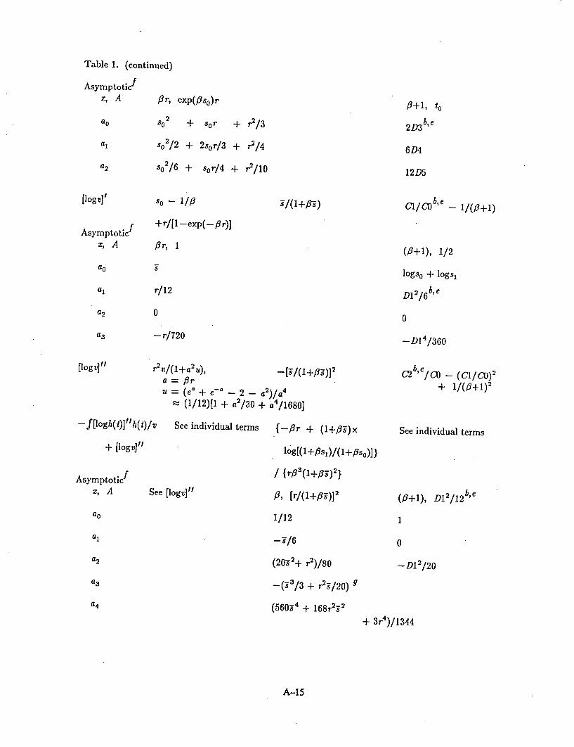
Table 1. (continued)
Asymptoticfx, A 13r, exp(,Bso)r
ao s02 + sor + r2 /3
a, SO2 /2 + 2 sor/3 + r2 /4
a2 SO2/6+ sor/4 + r2 /10
13+1, to
2D3b, e
6D4
12D5
[logvj'
Asymptoticfx, A
so- 1/
+r/[1-exp(-Pr)]
,B r, 1
Cl / C:O -1/(13+1)
aO
a,
a2
a3
r/12
0
- r/720
(13+1), 1/2
logso + logs,
D12/ 66,e
0
-D1 4 /360
[logv]"/ r2 u/(1+a2u),a = 13ru = (ea + ea - 2 - a2)/ 4
t (1/12)[1 + a2/30 + a4 /1680]
-f[logh(t)]"h(I)/v See individual terms {-,Br + (1+,63)x
+ flogv]I" log[(1+±1s 1)/(1+±6so)]}
Asymptotic' {r,83 (1-l63)2}x, A See [logv]" 13, [r/(l+±3s)] 2
ao 1/12
C2 be/a) - (Cl/Cu)2
+ 1/(13+1)2
See individual terms
(13+1), D1 2 /2 be
0a,
a2
a3
a4
(20-j2+ r2)/80
_3 3+ r23/20) g
(56Og4 + 168r2 32
-D1 2/20
+ 3r4)/1344
A-15

Table 1. (continued)
L'(0)/[1(0)1 "2 EE(ti-s1 ) EE(ts(i-ij) See text/[En .r 2/ 12] 1/2 /[Enrj 2/12]1/ 2
a. If the data are centered at .mid = Erj j/Erj, then lij, soj, and s1j must be replaced by tij-imids0j - mid, and sj- 'mid, respectively, and Evj and its derivatives are replaced by 0.
b. For the Weibull failure rate model, any terms involving so should be omitted if so= 0. In this case,the asymptotic expressions are not needed.
c. Equation numbers refer to defining equations in text.
d. The integral is for t from so to s,.
e. The notation Ck is defined as (s,/t0 )30[1log(s1 /to)]k - (so/to) '+l[1og(so/to)]k, for k = 0, 1, 2. Thenotation Dk is defined as {[log(s 1/to)]k-[log(so/to)]k)/k!, for k = 1, 2, 3, 4, 5.
f. The asymptotic approximation of the expression in the line immediately above is of the formAEakxk. The next lines give the variable z and the values of A, ao, a,, .... The expression may becomputed as A(ao + alx) if a2 z2 is numerically insignificant compared to ao. For example, under theexponential failure rate model, the asymptotic approximation for v isv ; exp(3iso)rl + (1/2),/r + (1/6)(pr)2 + ...].
Therefore, v may be computed as exp(flso)r(l + &r/2) if1 + (1ar)2 /6- 1
to the limits of the machine accuracy.
g. On a machine where a number has approximately 16 significant digits (IBM PC double precision),for 5-digit accuracy in all cases, including cases when s is virtually zero, the expansion for the linearhazard model should be evaluated out to the ,34 term. If this term is negligible compared to ao, theseries through the j 3 term should be used to evaluate the expression.
A-16

The constant AO is interpreted as the value of A(t) at time t = 0. This time 0 is customarily
taken to be the component's installation time, but any other time is allowed in principle. Measuring I
from a time other than the installation may make t negative, which is allowed. If each component has
a different AOj, the hazard function of each component changes by the same relative amount in any
specified time, but the hazard functions of the components are not equal. For example, the hazard
function doubles every (log2)/P time units, regardless of A0 j and regardless of what time is assigned
the value 0.
Linear Hazard Function
The hazard function is defined by
A(t) = A0 + at = .A0 (1 + fit),
with /3 measured in units of 1/time. This distribution is mentioned by Johnson and Kotz (1970b).
Salvia (1980) uses the model with test data, in which many components are tested until their first
failures. Vesely (1987) uses the model with field data for which failures from aging (corresponding to
the increasing portion of the hazard function) can be distinguished from failures from other causes
(corresponding to the constant portion of the hazard function). The cases considered by Salvia and
Vesely both turn out to be much simpler analytically than the cases considered in this report.
As with the exponential hazard model, it is possible that A has the specified form for the time
period for which data are observed, and some other form for other i. Therefore, it is possible for O to
be negative. However, /3 must not be such that A(t) is negative in the observed time period. In fact,
not even A(t) = 0 is allowed, because logA(t) is often used in the methods below. The details are
complicated by the fact that it is sometimes convenient to center the data, leading to observed times
expressed as negative values. Let sj and s8j be the beginning and ending observation times for
component j, following the unified notation defined above. To keep A(t) positive for all observed times,
/3 must satisfy /6 > -l/slj for all positive slj, and /3 < -1/sOj for all negative soj.
The constant A0 is the value of the hazard function at time t = 0. This time is the
component's installation time, or the central time, depending on how time is measured. Note that the
relative change in the hazard function approaches 0 as t -_ oo. For example when /3 > 0, the hazard
function doubles from the value at I = 0 in 1/fl time units, doubles again in the next 2/,6 time units,
A-17

and so forth.
Weibull Hazard Function
The hazard function is defined by
A(t) = AO(1/10) a
where to > 0 is a normalizing time. It is common (Johnson and Kotz, 1970a, Cox and Oakes, 1984) to
write the exponent as c - 1. The P notation is consistent with the other two examples because /3 = 0
corresponds to a constant failure rate. Both t and to have units of time, and /3 is dimensionless. The
constant AO is measured in units of 1/time, and is the value of the failure rate at time t = to.
Changing to does not change the value of /3, but does change the value of AO. For A(i) to be integrable
at 0, /3 must satisfy the constraint /3 > -1. Negative times are not allowed. If /6 > 0, A(0) equals 0;
if 3 < 0, A(0) is undefined.
The hazard function doubles between times tj and t2 if logt2 - log10 = (log 2)//3. Because
A(O) is either zero or undefined, the hazard function cannot double from the initial value.
3. LIKELIHOOD
3.1 Summary of Likelihood Formulas
In this section, the expressions for the likelihood are presented. All derivations and proofs are
given in Section 8.
Let C denote the number of components. Define
H(t;,6) = J h(u;/3) du
and
Vj (/3) H(s1 j;/3) - I(sOj;/3) (3)
Depending on whether the data are time- or failure-censored, vj is fixed or is the realization of a
random variable. The parameter /3 will sometimes not be shown.
A-18

The logarithm of the likelihood based on all the data is shown in Section 8 to be
C [,mn
Lpulm(,1, Lo\a *--, AOC) = , [iogh(tij;I3) + mjlogX0,- Aoivj(B)] . (4)
This follows the unified notation established earlier, with the interpretation of mj and slj depending on
the way the data for the jth component were generated. The values of Aoj may be distinct, or assumed
to all be equal to a common AO. In the latter case, Ljlu, depends only on 6l and AO, and can be
written as
Lfull(, Ao) = [ Elogh(tijj;f) + mjlogAo - Aovj(i)] (4')
Now consider the conditional distribution of the ordered failure times, conditional on the values
of nj or imj, whichever is random. The conditional log-likelihood is shown in Section 8 to be
Lco nd() = c [>logh(tiij;) - njlogv j(P) + log(nj!) ] (5)
C n.= E 1og{(nj!).t [h(t'j))3vj(3)]} (5')
From now on, the subscripts full and cond will be omitted, with the meaning being clear from the
number of parameters given as arguments of L. It is crucial to note that the conditional log-likelihood
(5) depends on /, but not on AO or the Aojs.
For component j, consider the term inside curly brackets in Expression (51), and suppress the
index j. The expression is the conditional joint density of the ordered failure times (T1 , ..., Ta).
Therefore, conditional on N = n or Tm = tm1 the n unordered failure times T, are independent and
identically distributed (i.i.d.), each with density h(t)/v on the interval [so, s1l, and density 0 outside
this interval. Therefore, inference for /3 can be performed in standard ways, based on observations that
are conditionally independent, and conditionally identically distributed for each component. This can
be done whether or not the components have a common value of AO.
Two other facts are needed to carry out inference for all the parameters. For time-censored
data, Nj is Poisson(Acovi). For failure-censored data, it is shown in Section 8 that 2AcO, VI has a
X2 (2mj) distribution. The values of AcO may or may not be assumed to equal some common value.
A-19

3.2 Ancillarity
Suppose that there is a multidimensional paramenter (13, 0), and a sufficient statistic (X, 1).
Y is said to be ancillary for if if the marginal distribution of Y does not depend on /3. X is called
conditionally sufficient for /3 if the conditional distribution of X given y does not depend on 0. When
these conditions hold, inference for / should be based on the conditional likelihood of X given y. When
maximum likelihood estimation is used, the same value for 13 is found whether the full likelihood or the
conditional likelihood is used, but the appropriate variance of , is the conditional variance. See
Kalbfleisch (1982) or Cox and Hinkley (1974, Sections 2.2viii and 4.8ii) for more information.
Return now to the setting of component failures, and consider time-censored data from C
components, when either (1) the components are not assumed to have a common value of AO, or (2) the
components have a common AO and all the vj's have a common value. In the examples of this report,
case (2) can occur only if all the components are observed over the same period so to sj. For case (1),
it is shown in Section 8 that (N1 , ..., Nc) is ancillary for 13, and that the failure times Tij form a
conditionally sufficient statistic for 1. (A lower dimensional conditionally sufficient statistic for i3 can
be determined in some examples by examining the form of EElogh(Ti,).) For case (2), the
components may be pooled into a single super-component, and N = DNj is ancillary for 13. In these
cases, therefore, basing inference for 3 on Equation (5) is not only possible but best. In all other cases,
basing inference for /3 on Equation (5) involves some loss of information.
3.3 Examples
The building blocks for the above formulas are all given in Table 1, at the end of this report.
A few points are worth noting here: The exponential hazard model is worked out in some detail by
Cox and Lewis (1966, Section 3.3). With this model, EElogh(Tij;P1) equals 13EETij, and it follows
that that EETij is conditionally sufficient for P3. For the linear hazard function, SElogh(T 1j;fl) equals
EElog(1 + 13Tij), and there is no one-dimensional statistic that is conditionally sufficient for l3. This
is one of several problems with the linear hazard model, which will be mentioned in this report as they
are encountered. For the Weibull hazard function, we have logh(T;fl) = jolog(T/10 ). Therefore,
EElogTij is conditionally sufficient for P3.
A-20

4. MAXIMUM LIKELIHOOD ESTIMATION
4.1 Maximum Likelihood Estimation Based on the Conditional Likelihood
If (N1, ..., NC) is ancillary for fl, then inference for fl should be based on the conditional log-
likelihood given by Equation (5). Even in other cases, one could use this conditional log-likelihood at
the cost of some loss of information. The maximum conditional likelihood equation is formed by
setting the derivative of Expression (5) with respect to j3 equal to 0, resulting in:
Zl Zs{ [logh(kijQ;)]' - [logvj(4 )]'l = 0 (6)
Here, the prime denotes the derivative with respect to /3. If /3 has dimension k, there are k such
equations, each involving the partial derivative with respect to one component of /3. The maximum
likelihood estimate (MLE) 3 typically is found by numerical iteration to solve Equation (6). If any
algebraic cancellation can be performed on the terms inside the curly brackets in Equation (6), then the
order of evaluation should be as suggested by the bracketing, for numerical accuracy. If no algebraic
cancellation can be performed, the evaluation may take advantage of the fact that Sj[logvj]'.
nj[logvj'.
Suppose that no common value of A0 is assumed. The MLE of A0j, corresponding to the jth
component, is A0j = mj/vj(/3). This is shown directly from Equation (4) by maximizing L(/3, AO, .
AOc) with respect to A0j. Suppose instead that a common value of A0 is assumed for all C
components. Then it is shown similarly that A0 = Emj/Evj(/3).
4.2 Maximum Likelihood Estimation Based on the Full Likelihood
Inference proceeds first by estimating A0, if a single common value is assumed, or by
estimating the various A0 j. Substitute the MLE(s) into the expression for the full log-likelihood,
differentiate the resulting expression with respect to /, and find the MLE /3.
When no common A0 is assumed, the equation for /3 is
C X-
(o/O/3)Lgi, A01, ..., I 4) _= E { [logh(41j;/fl' - plogv//3)]' =0 .(7)
A-21

This is identical to Equation (6), except that m appears in place of n. Therefore, use of either the
conditional or the full likelihood yields the same MLE ,3 from time-censored data; this agrees with the
conclusion of the ancillarity argument given earlier. For failure-censored data, Equation (7) differs
from Equation (6) by inclusion of the final failure times im and use of m = n + 1.
When a common A0 is assumed, the maximum likelihood equation for /l is
LiL,(v3, A0) = E [logh(tIj;f)]' - (Emj) [Evj'(/3)]/[vEj(/3)] = 0 . (8)j=1 j=l 1=1
This differs from Equation (6) in two ways: mi is used instead of nj, which makes a difference only
with failure-censored data; and the portion involving vi reverses the order of summation and
multiplication and division.
4.3 Examples
All the expressions used in Equations (6) through (8) are presented in Table 1, for the three
examples. A few points of interest are mentioned here. Typical features of all the models are discussed
using the first example as an illustration.
Exponential Hazard Function
Consider first estimation based on the conditional likelihood. The maximum conditional likeli-
hood equation for 6 is, from Equation (6) and the expressions given in Table 1,
C nj C C
E E (tij - so) + L nj/1 - nirj/[I - exp(-,3rj)] = 0 . (9)=1 i= j=1 =1
This agrees with the special case C = 1 and so = 0 worked out by Cox and Lewis (1966). It must be
solved numerically for 3. When ft is near 0, the last two terms in Equation (9) are very large,
although the difference is bounded. Therefore an asymptotic approximation should be used. From
expressions given in Table 1, a first order approximation is
E E+ }j=1 Fi ~(j - soj) - (rj/2)(1 + flr,/6) }=0
A-22

When 6 is small, this asymptotic approximation must be used to prevent complete loss of numerical
significance; of course, when /3 = 0 the limiting value must be used. Note. that 8 equals 0 when
that is, when the sum of the (non-replacement) failure times equals the corresponding sum of the mid-
points of the observation periods. This is intuitively consistent with the fact that when fl equals 0, the
conditional distribution of Tij is uniform on (so, sl). The MLE for AO or for the AOj's can be obtained
in a direct way from the results given above.
Inference based on the full likelihood is similar, using Equation (7) or (8) and expressions given
in Table 1.
Linear Hazard Function
It is straightforward to substitute the expressions for h(t) and vj into the general equations
given above. For example, consider the conditional log-likelihood based on a single component. Its
derivative is
L%(8) = Eti/(l + flij) -. n n/(l + /3)
It follows that the MLE /3, based on the conditional log-likelihood, equals zero if Mtj = Enjsj, just
as with the exponential hazard model. The following two points, however, deserve special notice:
The MLE , may be infinite. To see this, consider the expression for L'(fl) just given. If 1i >
1 for all i, then L'(,/) is positive for all /3. There is no finite solution to the maximum likelihood
equation. Thus, in cases when the evidence for an increasing failure rate is strongest, the rate of
increase may not be estimable by maximum likelihood.
With time-censored data and a common AO assumed, there is some advantage to centering the
data. In this case mi _ ni, and the full log-likelihood is
L(/3, AO) = EnilogAo + MElog(l + t j) - AoEri- AOErjsgj.
The last sum can be made to vanish by centering the data, that is, by measuring all times from
'mid = Erjsj / Erj
The log-likelihood then becomes
L(/3, Ao) = EnjlogAo + Mlog[1 + 6(lij - 'mid)] - Ao0r-
In this formulation, A0 equals the value of A(t) at i = tmid. If any value is assumed for /3, ENj is
A-23

Poisson(AoErj), independent of fi. Similarly, if any value is assumed for AO, L(3,Ao) is a function of
AO plus a function of , and the tij's; therefore, inference for fl is independent of AO. This ability to
perform independent inference for /3 and AO is a convenient property, which may be sufficient in the
eyes of some analysts to justify centering the data.
Suppose that when the data are uncentered, there is no finite MLE /3. Centering the data is
not a cure-all. When the data are centered, /3 is restricted to a finite range, as discussed in the
introduction to the linear hazard model in Section 2. In this case, the MLE II is at an end point of the
possible range; it is finite, but cannot be treated as asymptotically normal.
Weibull Hazard Function
In this case, [Pogh(ti j )J' = log(ti,/to). The remaining terms needed for Equations (6), (7), and
(8) depend on whether soj is zero or nonzero, and are all given in Table 1.
There is a noteworthy simplification in Equations (6) and (7) when soj = 0 for all j, that is,
when every component is observed from its time of installation. In this case, [logv]' equals log(sl/t&)
-1/(,3 + 1), and Equation (6) has the explicit solution
/3 = -En j/EIlog(1ij/s 1 j) - 1 . (10)
The solution of Equation (7) replaces nj by mj. These are the only cases considered in this report for
which the MLE /3 can be found without numerical iteration.
In this case, the value /3 satisfying Equation (6) equals 0 not when MEtij equals Enjsj, as in
the other examples, but when
-EElog(t j/s1 j) = n .
This initially surprising fact has the following intuitive basis. For notational simplicity, consider a
single component, suppress the index i, let to = 1, and condition the observations on the value of n or
sl. To derive the conditional distribution of -log(Tl/sl), begin with
P[-log(T*/sl) > a 1 = P[ Tj < slexp(-x) ]
Following the discussion below Equation (5), Ti has conditional density h(t)/tr, therefore, this
probability equals
J[slexp(-r)]p+ /(P + 1)} / {s1 ''/(fl + 1)} = exp[-x(,3 + 1)]
Therefore, the conditional distribution of -log(Tl/sl) is exponential with mean y = 1/(13 + 1).
A-24

Equation (10) can be rewritten as
-EElog(ji1/s1 j) / Enj = 1/(/ + 1) = p
that is, the MLE is based on equating the mean of -log(Tij/slj) to the sample mean. In particular,
the case /3 = 0 corresponds to Ai = 1, that is, -EElog(tij/s 1 j) / Enj = 1.
When the values of soj are not all zero, the expressions are more complicated, but the maxi-
mum likelihood equation is still equivalent to setting the mean of EElogTij equal to its sample mean.
5. CONFIDENCE REGIONS AND HYPOTHESIS TESTS
The standard regularity conditions, such as given by Cox and Hinkley (1974, Section 9.1) are
assumed. The assumptions involving the parameter space, identifiability of the distributions, and
existence of derivatives are all satisfied in the examples considered in this report. There is also an
assumption involving the behavior of the third derivative of the log-likelihood as n goes to infinity.
For field data, such an assumption is typically difficult to affirm or deny. Practitioners must always
treat asymptotic approximations with care.
5.1 Inference Based on the Conditional Likelihood
The procedure described here might be used when /3 is the primary parameter of interest, or
when (N1, ..., Nc) is ancillary for 63. The presentation here assumes that 63 is one-dimensional. The
generalizations to multidimensional /3 are straightforward. We remark in passing that when logh(t) is
linear in one-dimensional 63, as is the case for the exponential and Weibull models, then the one-sided
tests given below are uniformly most powerful.
Inference for /3
The derivative with respect to /6 of the conditional log-likelihood, L%(/3), is given by Equation
(6). The information is
I(^) = -EtL"(,3)) = El [L'(,8)]2 }
A-25

= -E E E [ogh(;ij! - 1n. Pogvj(0)]1'}
= Ejnj{-f [1ogh(t;#)]"hi(i;)3) dt/v,(j1) + [logvj(,O)"} * (11)
If , is k-dimensional, I(13) is the kxk matrix defined by taking all the mixed partial derivatives of L.
Let , be the true value. Under the assumed regularity conditions, the expectation of L%(3) is 0, and
the variance (or covariance matrix for k-dimensional 13) of L%(13) is 1(,1).
As a corollary to the Lindeberg-Feller Central Limit Theorem, Feller (1968, Section X.5) gives
a sufficient condition for asymptotic normality of L'(#). Rewrite Equation (6) as L'(p) = rEXk. If
there is a constant A such that IXkI < A for all k, and if (11) -_ co, then
L'(,3 0) / [1(130)]1/2 (12)
converges in distribution to normal(0,1). The assumptions must be verified for each example.
Typically, the assumptions are satisfied if all the values of s~i and slj are bounded by some constant,
and if some fixed fraction of the ri's is bounded away from 0. For the exponential hazard model, it is
enough for the rj's to be bounded by some constant and for a fixed fraction to be bounded away from
0. For the linear hazard model, it is necessary in addition for 1 + 13soj and 1 + Oslj to be uniformly
bounded away from 0. Qualitatively, the approximation is best if the soj's are approximately equal
and if the s1 j's are approximately equal. The approximation also is better if ,3 and h are such that
[logh(T 1j;,8)]' does not have a highly skewed distribution. If it is very important to know whether the
normal approximation is adequate in some application, a simulation study should be performed.
An approximate confidence interval for l3 is the set of all 130 such that the statistic (12) lies in
the interval (-c, c), where c is the appropriate number from a normal table; for example, c = 1.96
yields an approximate 95% confidence interval. Actually, this defines a confidence region for 13. To
show that the region is an interval rather than some more complicated set, one must show that
Expression (12) is a monotone function of 83. Alonotonicity is difficult to show analytically. -It can be
checked numerically by a computer program in any example. In experience so far with real data, (12)
has always been monotone for the exponential hazard model, but has not always been monotone with
the linear hazard model when the confidence interval was unbounded, or for the Weibull hazard model
near 3 = -1.
To test the hypothesis 13 = 13o for some particular value Po, the test statistic (12) can be used,
A-26

and the hypothesis rejected if the test statistic is in an extreme tail of the normal distribution. In
particular, the hypothesis P = 0 is often of interest; the test statistic (12) may then have an especially
simple form, as discussed below for the examples.
Infcrence for A0
Once a value of 13 is assumed, it is easy to find a confidence interval for AO or confidence
intervals for the various Auj's. The method is shown here when the components are assumed to have a
single common A0 .
For time-censored data, define N = E2N, and v = v with v evaluated at the assumed value
of 13. Because N is Poisson(A0 Svj), a two-sided 100(l - a)% confidence interval for A0 is given by
Johnson and Kotz (1969, Section 6.2) as
AOL =X 2,,/2/(2v)
AOU = 22(n + 1),1 - a/ 2 /(2v) * (13)
If instead the data are failure-censored, define m = Emj and v = Evj with v evaluated at the
assumed value of 6. Because 2AOV has a X2 (2m) distribution, a two-sided 100(1-a)% confidence
interval for A0 is given by
AOL = X 22m.,/2/(2v)
AOU = X2 2m,1 _- (/ 2 /(2v) . (14)
Note that Formulas (13) and (14) agree except for the degrees of freedom.
A two-dimensional confidence region, with confidence coefficient approximately 100(1 -ca)%,
can be formed as follows. Form a 100(1 - ca/2)% confidence region for 13. At each 130 in the
confidence interval, evaluate v and form the resulting 100(1 - a/2)% confidence interval for A0. The
approximation results from the use of a large-sample approximation for the confidence interval for 1,
and from the way the two individual confidence coefficients are combined to yield a joint confidence
coefficient.
If /3 is treated as known and equal to 13, Equations (13) or (14) give an approximate confidence
interval for AO. It is too short, however, because it does not account for the randomness of the
estimator B. If this interval for AO depends strongly on the assumed value of 1f, a more exact
A-27

confidence interval is obtained by taking the largest and smallest values of AO in the two-dimensional
region for (dl, AO).
A conservative confidence interval for the hazard function A(t) is given by the largest and
smallest values of A(t) attained in the two-dimensional confidence region for (fl, AO).
5.2 Inference Based on the Full Likelihood
When all the model parameters are of interest, an analyst either could follow the procedure
presented above, or could perform inference based on the full model as follows. The discussion assumes
that all the components have a common A0. Formulas for A0 will be based on joint asymptotic
normality. There are heuristic arguments for why parameterization in terms of p = logAO improves
the normal approximation: for failure-censored data, this transformation replaces the scale parameter
A0 by a location parameter; also, the log transformation of Equations (13) and (14) yields more nearly
symmetrical intervals.
The log-likelihood L(13, AO) is given by Equation (4'). The sample information matrix for (,
P) (1, logA0 ) is
(8 2 /a13 2 )L(3, AO) (9 2/0139p)L(8, AO)SI(#, logAo) =alq -0/P L 2/a ap)L( ,, AO) ( 2 /0p2 )L(j3, A)
-{1 i11ogh('ijj]T1} + AOvjIt AOvj1= {Th~lo~h~iu~iu} j. (15)
Aovjl mj
In some situations, evaluation of the above terms at (13, A0) is made easier by using the identities
E mj/So = Ev and EE[logh(iij)]' = A Ev1 , with the second identity following from Equation (8)
evaluated at (0, A0 ).
The information matrix is then defined by
1(13, logAO) = E[SI(3, logAo)J -
The expectation is based on the randomness of Tij and of either Vi or Mlj. Depending on the form of
A-28

A, the analyst may choose to estimate the information matrix by 1(13, logAO) or by SI(/3, logAO); see
Cox and Hinkley (1974, p. 302). In practice, expecially when Vj is random, it is much more
convenient to use SI to estimate A(O, logAO).
Asymptotic inference is based on the fact that (13, logio) is asymptotically normal with mean
(l, IogAO) and covariance matrix r 1(fl, logAO). This allows for approximate confidence intervals for
1, for AO, and for functions of the two parameters, such as A(t). To do the last, write
logA(I) = logo + logh(i;/) -
Take the first-order Taylor expansion of logh(ft;,) around fi = 13. This yields the asymptotic distribu-
tion of logh(i;h), and its asymptotic covariance with logAO. Then logA(f) is asymptotically normal,
with mean equal to the sum of the means, and variance equal to the sum of the variances plus twice
the covariance. This may be used for t such that the Taylor approximation is adequate.
5.3 Examples
The building blocks for the formulas are all given in Table 1. Asymptotic approximations are
also given, to be used when , is near 0 with an exponential or linear hazard function, and when 13 is
near -1 with a Weibull hazard function. Special cases are now considered.
Exponential iHazard Function
To test if = 0, based on the conditional log-likelihood, the asymptotic formulas in Table 1
show that the test statistic (12) equals
j{iij -njuj1 }/[Ej njrj2/12]i/2 (16)
Here i goes from 1 to nj. When there is just one component (j = 1), the statistic becomes
[Eiti/n -s]/[r/(12n)1/2],
which has a simple intuitive interpretation. If the failure rate is constant (13 0), the conditional
distribution of the failure times for the component is uniform between so and sl. The test statistic is
the average observed time minus the midpoint of the observation period, all divided by the standard de-
viation of an average of uniformly distributed variables. This test was first proposed by Laplace in
1773, according to Bartholemew (1955).
A-29

In this case, logA(i) = logA0 + fli. Therefore, the asymptotic distribution of logAQ() follows
neatly from the asymptotic distribution of (/3, logA0 ).
Linear Hazard Function
Recall that time-censored data can be centered. This redefines the meaning of A0 and /, the
function h(f) becomes 1 + 3(1 - 'mid), and Evjp equals 0. The sample information matrix (15) then
becomes a diagonal matrix, and /3 and A0 are asymptotically uncorrelated.
The test of /3 = 0, based on the conditional log-likelihood, can be built from the elements in
Table 1. The statistic is given by Expression (16). That is, the natural large-sample test of constant
failure rate is the same, whether an exponential or linear hazard model is postulated.
The asymptotic distribution of A(t) is obtained by making the approximation
logh(l;B) _ log(1 + /3t) + (3-/)t/(1 + fit)
The approximation may be used when the second term is small compared to 1. For practical use, the
approximation is good enough if twice the standard deviation of S/3(1 + flt) is less than 0.1, and fair
if this standard deviation is less than 0.5.
Weibull Hazard Function
The necessary expressions are given in Table 1. In this model, the test statistic (12) differs
from Expression (16). When all the values of sO equal 0, the test statistic simplifies to
{EE[log(tiI/sl) + 1]} / (Enj)1 /2, (17)
with i going from 1 to nj. Recall from the discussion of maximum likelihood estimation below Equa-
tion (10) that the conditional distribution of -log(Tij/slj) is exponential with mean and variance
equal to 1/(, + 1), and that the MLE of 1/(/3 + 1) is the sample mean of the terms -log(tij/s1 j).
Therefore, the negative of the test statistic (17) can be written as the MLE of 1/(&6 + 1) standardized
by the mean and variance when l3 = 0.
The estimated hazard function satisfies A(t) = logA0 + ,log(i/t 0 ), so the asymptotic normal
distribution follows directly from the corresponding result for (p3, logA0 ).
A-30

6. DIAGNOSTIC CHECKS
The methods presented above have assumed a common value of /3 for all components, perhaps
a common value of A0, and a hazard function of the form ALh(t;/3). Computations are often based on
the assumption that asymptotic normality yields an adequate approximation. Diagnostic checks-both
tests and plots-should be used to investigate the validity of these assumptions.
6.1 Common /3
To see if a particular component, the kth say, has /3 significantly different from the other
components, calculate the MLE based on the kth component only and on all components (pooled)
except the kth. At this point there is no reason for confidence that the components have a common A0;
therefore, use the MLE based on the conditional likelihood, which is independent of the value(s) of A0 .
The difference /k - /L_ has variance equal to the sum of the variances, and mean zero if all
components have the same fl. Therefore it yields a test, using asymptotic normality, of the hypothesis
that the kth component has the same /3 as do the others. The C tests can be combined using the
Bonferroni inequality to form an overall test of the hypothesis that the components have a common /l.
If any component has no nonreplacement failures, /3 cannot be estimated for that component, and
fewer than C test statistics and confidence intervals can be calculated.
A single component may not have enough failures to justify asymptotic methods. In the
extreme case when the kth component has only one non-replacement failure, a practical expedient is to
treat /3-k as known, and test whether p3k = /-k. based on the single observed failure time for the kth
component. This test is based on the fact that the single failure has conditional density h(i)Ivk, with /3
set to fl-k.
In addition to the test for common /3, a useful visual diagnostic is a plot of C confidence
intervals for the parameter, placed side by side, with each interval based on the data from a single
component.
6.2 Common A0
Suppose that the assumption of a common /3 is accepted, and consider how to test whether the
components have a common A0 . Treat /3 as known and equal to /; this introduces an approximation
A-31

into the tests for AO, but it does not a priori treat any component differently from any other. Consider
now the kth component, pool all the components except the kth, and test whether A0O, equals AO-k
Assume for the moment the null hypothesis that the components have a common AO.
With time-censored data, the conditional distribution of Nk, conditional on the ancillary statis-
tic Enj, is binomial(Enj, pk), with pk = vk()/Evj(P). This yields a test of the hypothesis that AOk
is the same as AO for the other components. These tests may be combined with the Bonferroni
inequality. Alternatively, if the failure counts are not too small, a x2 test may be used, based on the
fact that (N1, ..., Nc) is multinomial (Enj, Pi, ..., Pc).
With failure-censored data, the distribution of 2Ao Vt(,8) is X2(2mk), and the sum of the
observation periods for all components except the kth is likewise proportional to a x2 random variable.
Therefore the ratio of Vk to the sum of such terms over all components except the kth is proportional
to an F random variable. This yields a test of the hypothesis that AOk is the same as A0 for the other
components. The tests may be combined with the Bonferroni inequality.
As when comparing the components for fl, a side-by-side plot of confidence intervals for A
provides useful visual diagnostic information.
6.3 Form of h(t)
To test whether h is of the assumed form, use the fact that for the jth component, conditional
on the observed failure count nj or on the final observation time sli, the Tfj's are independent and for
each component are identically distributed, with density proportional to h, as discussed below Equation
(51). Therefore, under the assumed model, the conditional probability that a random failure T occurs
by. time t is
P[T < t] = 7P[T < t failure is in component JI P[failure is in component j]
= 7PtT < t failure is in component 33 (nj/Eni)
with
P[T < I I failure is in component )] = [H(t) - H(s0j)I/vj if s~j < t < Slj
= 0 if t < sOj
= 1 if t > sj.
Tests for a hypothesized distribution may now be used, such as the Kolmogorov-Smirnov test or the
A-32

Anderson-Darling test.
Routine use of one of these tests gives a Type I error smaller than the nominal value; the test
tends not to reject often enough. There are two reasons for this. One is the familiar reason that the
estimated value of /3 must be used to evaluate H and v. The second reason arises if the components
are observed over different time periods. The distribution used is conditional on the failure counts or
final failure times, so the Tij's are not truly a random sample. As an extreme example, suppose that
component 1 was observed for only the first year of its life and that it had n1 failures, that component
2 was observed for only the second year of its life and that it had n2 failures, and so forth. The
conditional distribution then says that of Snj failures in the first C years, on the average ni will occur
in year i. The Ti1 's are a stratified sample from this distribution, and are therefore forced to fit the
distribution rather well. They fit well regardless of the form of h, because the stratification does not
involve the hypothesized h.
To avoid this difficulty, it is good to try to use components that are observed over the same
time period; if a few components have-a different observation window from all the others, try partition-
ing the data and performing the test on the two sets separately. In the extreme case given by the
above example, the following method could be used. Find 3 using all the data, and treat it as known.
Then for each of the C components perform a separate Kolmogorov-Smirnov test of Ho: , = /. This
yields p1 , ..., Pc, the attained significance levels or p-values. It is well-known that under Ho, a p-value
is uniformly distributed on (0, 1), so that -2Sog(pj) has a XN2(20) distribution. Thus Ho would be
rejected at level a if -2Sog(p1 ) > X21 .. (2C).
Two pictures may accompany the test. One is the plot of the above model-based c.d.f.
overlayed with the empirical c.d.f.. The other is a Q-Q plot, as described, for example, by Snee and
Pfeifer (1983). It plots the n observed failure times versus the inverse of the model-based c.d.f.
evaluated at 1/(n + 1), ... , n/(n + 1).
6.4 Adequacy of Asymptotic Normal Approximation
An MLE can be inspected to see if it is near the mid-point of a two-sided confidence interval; if
not, the normal approximation may not be adequate. Also, a two-dimensional confidence region for
(/3, logA0 ) can be constructed from an interval for /3 and conditional intervals for A0 given A, as
A-33

discussed below Equation (14). This can then be compared to the confidence ellipse based on the
asymptotic joint normality of (/3, logA0 ). If the two regions are very different, approximate joint
normality should be questioned.
7. EXAMPLE DATA ANALYSIS
A nuclear power plant for a commercial utility has 12 motor-operated valves in the auxiliary
feedwater systems at the two units of the plant. Maintenance records covering about 10 years were
examined, and the failure times for the valves were tabulated. The data are summarized in Table 2,
and are given in more detail by Wolford et al. (1990). Three valves were replaced upon failure, and
one was replaced for administrative reasons, leading to 16 valves shown in Table 2. The three valves
that were replaced upon failure were regarded as failure-censored. The other 13 valves were regarded as
time-censored. A Fortran program PHAZE (for Parametric HAZard Estimation) was written and used
on a personal computer to analyze the data, following the methods of this report; the program is
documented by Atwood (1990).
The valves were first compared to see if they have clearly different values of fi. Figure 1 shows
a side-by-side plot of the confidence intervals based on the individual components. It also shows the
significance levels based on a comparison of Is, to /-k. The diamond in each confidence interval
shows 1k while the square shows /-k. Note that there is no estimate or interval for components with
no non-replacement failures. The overall significance level, based on the Bonferroni combination of the
individual significance levels, is 1.0, confirming the pictorial impression that there is no real difference
in /3 for the various components. The exponential hazard function was assumed for these calculations.
The results were similar when the linear or Weibull hazard function was assumed. The only striking
difference was that many of the MLEs and all of the upper confidence limits were infinite with the
linear hazard function. A similar comparison of the components for AO led to a conclusion that the
components do not have greatly different values of AO. Therefore, the components were assumed to
have a common value of jJ and of AO.
Tests of 3 = 0 were performed based on the test statistic (12), and the hypothesis was rejected
in favor of 3 > 0. The test based on EEtij, when Expression (12) takes the form of Expression (16),
rejected at one-sided level 0.021. The test based on EElogtij, when Expression (12) is evaluated under
the Weibull model, rejected at one-sided level 0.025.
A-34
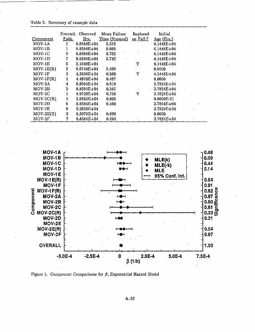
Table 2. Summary of example data
Nonrepl. Observed Mean Failure Replaced InitialComponentMOV-1AMOV-1BMOV-1CMOV-1DMOV-1EMOV-1E(R)MOV-1FMOV-1F(R)MOV-2AMOV-2BMOV-2CMOV-2C(R)MOV-2DMOV-2EMOV-2E(R)MOV-2F
Fails.1127033145116027
Hrs. Time (Normed)8.8584E+04 0.3788.8584E+04 0.0868.8584E+04 0.7528.8584E+04 0.7432.1840E+046.6744E+04 0.4984.3608E+04 0.5684.4976E+04 0.4878.8584E+04 0.6198.8584E+04 0.5674.9728E+04 0.7563.8856E+04 0.8668.8584E+04 0.4642.2608E+046.5976E+04 0.6988.8584E+04 0.593
on Fail.? Age (Hrs.)4.1448E+044.1448E+044.1448E+044.1448E+04
Y 4.1448E+040.0000
Y 4.1448E+040.00003.7824E+043.7824E+04
Y 3.7824E+040.OOOOE-013.7824E+043.7824E+040.00003.7824E+04
MOV-1AMOV-t B
0
0C.)
MOV-1DMOV-1E
MOV-1 E(R)MOV-1 F
MOV-1 F(R)MOV-2AMOV-2BMOV-2C
MOV-2C(R)MOV-2DMOV-2E
MOV-2E(R)MOV-2F
OVERALL
._ * MLE(k)* MLE(-k)
- 95% Conf. Int.
I'
I'I * , I
.I
0.480.090.440.14
0.640.91
00.82 u0.87 e0.80 o0.61 ',
-0.33 -90.21
0.540.97
1.00
7.5E-4
HIH
S
-5.0E-4 -2.5E-4 0 2.5E-4Ji (1 /h)
5.0E-4
Figure 1. Component Comparisons for fi, Exponential Hazard Model
A-35

To test the form of the model, the Kolmogorov-Smirnov test was performed, as described in
Section 6.3. The test saw nothing wrong with any of the three models; the three significance levels
were all greater than 0.8. To account for the partial stratification of the data, the components were
partitioned into two groups, the twelve that were in place at the start of observation, and the four that
were installed during the observation period. The overall MLE, based on the conditional likelihood for
all the components, was used to estimate Pi. This value was treated as known in the two data sets,
and the Kolmogorov-Smirnov test was used to test the fit of each data set to each of the three models.
The three significance levels corresponding to the larger data set were calculated using asymptotic
formulas and were all greater than 0.79; the significance levels corresponding to the smaller data set
(seven failures) were not calculated exactly but were all substantially greater than 0.20. Even allowing
for the fact that the hypothesized model had an estimated parameter, it seems that the data give no
reason to question any of the three models.
Figure 2 shows the Q-Q plot of the full data set, based on the exponential hazard model. Q-Q
plots based on the other models look similar. The only evident departure from the assumed model is
shown by several strings of nearly vertical dots, indicating repairs that cluster in time. The effect of
this clustering is ignored below.
For each model, an approximate two-dimensional 90% confidence region was found for (/L,
logAo), as discussed below Equation (14). Similarly, a 90% confidence ellipse was found based on the
asymptotic normality of (/3, logA0 ). These two regions are superimposed in Figure 3 for the exponen-
tial hazard function, and in Figures 4 and 5 for the linear and Weibull hazard functions. The circle
and the ellipse show the MLE and the confidence region based on the full likelihood and asymptotic
normality, while the square and the non-elliptical region show the MLE and confidence region based on
the conditional likelihood. For the linear model the data were centered, and for the Weibull model the
normalizing to was set to Imid. For the exponential and Weibull models, the regions overlap fairly
well, suggesting that the asymptotic distribution is an adequate approximation. For the linear hazard
function, the confidence regions must be truncated at the maximum allowed value for /3. Therefore the
normal approximation is not adequate. By the way, when the linear hazard model was used with
uncentered data, the confidence regions were as shown in Figure 6. The non-elliptical region is thin
and strongly curved, and it hardly overlaps the truncated ellipse at all; therefore, centering seems to
improve the normal approximation, even though the approximation still is inadequate.
A-36

1.2E5
gl .0E5
02_
< 8.0E4Cu
0as
.: 6.0E40
cow
: 4.OE4'a
0
2.0E4
.3-p1/.
fI.�Sd,
/A
/0
I I I I t. , XI
0 2.0E4 4.0E4 6.0E4 8.0E4 I.0E5Observed Age at Failure (h).
1.2E5
Figure 2. Q-Q Plot for Exponential Hazard Model
A-37

3.0E-5
2.5E-5
2.0E-5
1.5E-5
1 .OE-5
5.0E-6
nOw 3 4 5 6 7 8 1O 1 2 Z5s3 4 5 6
0Xo (1/h)
Figure 3. 90% Confidence Regions for (dl, AO), Based on Exponential Hazard Model
1 .50E-5
1.25E-5
1 .OOE-5
- 7.50E-6
5.0OE-6 -
2.50 E-6-
o ........ , , , , ., .,, I ,12 25 3 3.5 4 4.5 5 5
Xo (1 /h)
Figure 4. 90% Confidence Regions for (/3, A0), Based on Linear Hazard
10-4
Model, Centered Data
A-38

1.8
1.6
1.4 -
1.2
1.0
<- 0.8
0.6
0.4
0.2
0.0
-0.2 22
Figure 5. 90%
8.0E-4
6.OE-4
4.OE-4
2.0E-4
0
2.5 3 3.5 4 4.5 5 6 7 8 9
lo (1 /h) 1 0-4
Confidence Regions for (Ii, AO), Based on Weibull Hazard Model, Uncentered Data
U====
v3 n A . ,, I I I I II . .9.,.. .I .- I. I .,. I I I I I I ,..I - I..I . I-
4 5 1.5 2 3 4 a 1.5 2 3 4 510-6 1-o (I Sh) I0-5
Figure 6. 90% Confidence Regions for (/6, AO), Based on Linear Hazard Model, Uncentered Data
A-39

Finally, the hazard function was estimated with a confidence interval based on the asymptotic
joint normal approximation. In spite of the poorness of the joint normal approximation for the linear
hazard model, the method was used for all three models, for comparative purposes. Figure 7 shows the
MLE and 90% confidence interval for A(t), at various values of t, for the three models. If the
confidence band for the linear hazard model were seriously advocated, it would be plotted only for
values of t satisfying
2 sd t/(1+,t) < 0.5,
where sd is the estimated standard deviation of /; outside this range, the first-order Taylor approxima-
tion of logh(t;j3) is inadequate. This restriction corresponds to requiring t > 1.6E4 h. If the upper
and lower bounds for the linear model are ignored where t < 1.6E4 h, the bands for the three models
look similar, except that the Weibull hazard function approaches 0 at time 0. Most of the components
were observed between ages 4.1E4 h and 13.0E4 h. It is not surprising that the confidence intervals are
narrowest [in the scale of logA(l)] in the middle of this period of the observed data. If the model were
extrapolated far beyond the data, the uncertainties would become very large.
8. DERIVATIONS AND PROOFS
The likelihood formulas developed here have long been known; for example, see Equations (2.1)
and (3.1) of Boswell (1966), or Bain et al. (1985). The derivations are sketched here for completeness.
Consider a single component. The fundamental idea to be used repeatedly here is that the trans-
formation
u(t) = A(t) - A(so)
converts the non-homogeneous Poisson process to a homogeneous one with unit rate. That is, the
count of events occurring at transformed times u(t) with u(a) < u(t) < u(b) is Poisson with parameter
u(b) - u(a), and counts for disjoint intervals are independent. For such a homogeneous process, it is
well known that the time between successive events is exponential with parameter 1.0. Likelihood
formulas may be derived using the relation between the density of t, denoted by f, and the density of
u(t), denoted by 9:
J(t) = gAu(M)] 19u(t)/01I = exp[-u(W)]A(t)
ttjlti_1) = g[u(tj)Iu(1._1)]A(1i) = exp[u(it_) - u(ti)]A(ti)
Here, J(Iilti;_) is the conditional density of a failure at time ti, conditional on the component's being
operable (restored to service) at time li-.
A40
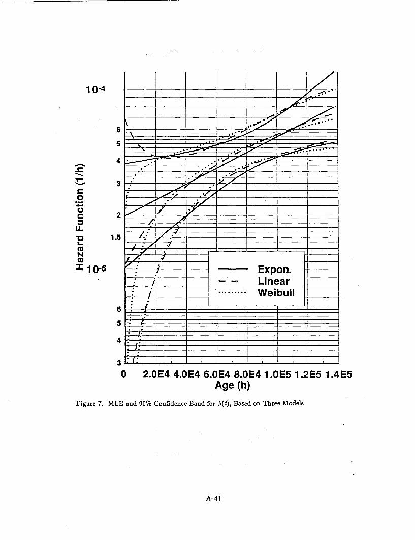
10-4 1,l..
6 ds
4 .5
4 .- S. ____=___ ______
.0 ' t.'~~~~~~~~~~~~-;f tat .
1 1.5 X , 1.
N
I 10-5 ! * _iExpon.
. i -- Linear* X~ ~~..... We! Ul
6 I
5
0 2.0E4 4._E4 6.0E4 8.0E4 1.0E5 1.2E5 14E5
Age (h)Figure 7. MLE and 90% Confidence Band for A(t), Based on Three Models
A-41

8.1 Derivation for Time-Censored Data
The Likelihood
Consider a single component and suppress the subscript j and the argument /?. Suppose that a
random number of failures is observed in a fixed time interval (so, Sl], and that the ordered failure
times are il, ..., in. In the formulas below, define to = so and u, = u(ti). Note that U(so) = 0 and
u(sl) = Aov. The likelihood is the joint density of the observed failure times, multiplied by the proba-
bility of no failures after 4n; that is,
If u1 11 (f Ao) = [HAtilti l)] exp[A(in) - A(s 1 )]
- [HlA(id)][IexP(u1 i- - ti;] exp[un - u(si)]
= Ao" [rlh(li)] exp(-Aov), (18)
Taking logs and summing over the components yields Equation (4), as claimed.
For a single component, consider now the conditional distribution of the failure times given n.
Because N is Poisson(Aov), the probability of n failures is
exp(-AOv) (POv)" / n! * (19)
Therefore the conditional likelihood, the likelihood corresponding to the conditional distribution of t1,
.,n given n, is the quotient of Expression (18) divided by Expression (19):
1cond(#) =Th(t;)] (V)-n n!-
Taking logs and summing over components yields Equation (5), as claimed.
Ancillarity
Consider again a single component. The failure count N is ancillary for '8. To see this, define
M = Aov. Reparameterize so that the parameters defining the model are P and /3. Then N is
Poisson(p), so the distribution of N involves only p, not fl. Given N = n, the unordered failure times
Ti are i.i.d., each with density h(t)/v on the interval [so, sl]. This conditional density depends on 3
A-42

only, not on p. Therefore, N is ancillary for I3 and (T1 , ..., Tn) is conditionally sufficient for /3.
Suppose now that there are C components, C > 1, and that the components are not assumed
to have a common value of A0 . Then (N1, ..., Nc) forms a C-dimensional ancillary statistic for /3.
This is easily shown by a generalization of the above argument for a single component, parameterizing
the model in terms of /3 and (pi, ..., pc), with pj = X0 jvj.
Similarly, suppose that there are C components with a common value of AO, and that vj has
the same value v for all the components, regardless of /3. (Remark: In the three examples of this
report, this can occur only if the components all have a common value of so and s1. To see this, set vj
= Vk and = vk'. Evaluate these quantities at / = 0 using the formulas of Table 1. It follows
that soj = 80k and slj = s8 k; this is immediate for the exponential and linear hazard function, and
can be shown with a little effort for the Weibull hazard function.) Now set P = Aov and note that N
= ENj is Poisson(Cp). Consider the conditional log-likelihood analogous to Expression (5), only now
conditional on n rather than on (n1, ..., n It is equal to
C 3logl(n!)C C" l I1 h(thN)/1]}
j=1 i=l
This is the log of the conditional density of the ordered failure times, with each time assigned at
random to one of the C components. Therefore, the Tjj's are conditionally i.i.d., each with conditional
density h(i)/v for so < t < sl. The components may therefore be pooled as a single super-component,
and N = ENj is ancillary for 8.
Finally, suppose that there are C components, C > 1, that the vj's are not all equal, and that
the components are assumed to have a common value of A0. There does not seem to be a reparameteri-
zation such that the distribution of (N., ..., NC) is independent of /3. Therefore (N1, ..., Nc) does not
appear to be ancillary. To show conclusively that (N., ..., Nc) is not ancillary, we note that Equations
(6) and (8) yield different values of /.
8.2 Derivation for Failure-Censored Data
Now suppose that a single component is observed starting at time so, and that m failures are
observed, with m fixed. The full likelihood is the joint density of the failure times:
A-43

lf-,(p, AO) = I
= [HA(Ij) exp(uo - um)
- Aion[j'h(ti)] exp(-Ache)] (20)
Taking logs and summing yields Equation (4).
To condition on the value t1,a the distribution of Tm must first be derived.
THEOREM. The time to the mth failure Tm has density
fm(tm) = Wm-l CWA(tm) / (m-1)! (21)
where w = A(tm) - A(so), and im > so
COROLLARY. Define AOVby A(Tm) - A(so). Then 2A0 Vhas a X2 (2m) distribution.
PROOF OF THEOREM. Here, w _- u(tm), the mth transformed failure time. Because the trans-
formed failure times correspond to a Poisson process with unit rate, it is. well known that the mth
transformed time has a gamma distribution. The asserted result follows. 0
The conditional distribution of (T1 , ..., Tm) given Tm = Im is (20) divided by (21). Take
logs and sum over the components to show that Lcond(fl) is exactly equal to Expression (5).
A-44

9. REFERENCES
Corwin L. Atwood, User's Guide to PHAZE, a Computer Program for Parametric Hazard Function
Estimation, EGG-SSRE-9017, 1990.
Lee J. Bain, Max Engelhardt, and F. T. Wright, "Tests for an Increasing Trend in the Intensity of a
Poisson Process: A Power Study," Journal of the American Statistical Association, 80, 1985, pp. 419-
422.
D. J. Bartholomew, Discussion of article by D. R. Cox, Journal of the Royal Statistical Society, Series
B, 17, 1955, pp. 162-163.
M. T. Boswell, 'Estimating and Testing Trend in a Stochastic Process of Poisson Type," Annals of
Mathematical Statistics, 37, 1966, pp. 1564-1573.
D. R. Cox and D. V. Hinkley, Theoretical Statistics, London: Chapman and Hall, 1974.
D. R. Cox and Valerie Isham, Point Processes, London: Chapman and Hall, 1980.
D. R. Cox and P. A. W. Lewis, The Statistical Analysis of Series of Events, London: Chapman and
Hall, 1966.
D. R. Cox and D. Oakes, Analysis of Survival Data, London: Chapman and Hall, 1984.
William Feller, An Introduction to Probability Theory and Its Applications, Volume I, Third Edition,
New York: John Wiley & Sons, 1968.
Norman L. Johnson and Samuel Kotz, Discrete Distributions, New York: John Wiley & Sons, 1969.
Norman L. Johnson and Samuel Kotz, Continuous Univariate Distributions - 1, New York: John Wiley
& Sons, 1970a.
Norman L. Johnson and Samuel Kotz, Continuous Univariate Distributions - 2, New York: John Wiley
& Sons, 1970b.
A-45

John D. Kalbfleisch, 'Ancillary Statistics," Encyclopedia of Statistical Sciences, Vol. 1, S. Kotz and N.
L. Johnson, eds., New York: John Wiley & Sons, 1982.
Alan F. Karr, "Poisson Processes," Encyclopedia of Statistical Sciences, Vol. 7, S. Kotz and N. L.
Johnson, eds., New York: John Wiley & Sons, 1986.
Paul L. Meyer, Introductory Probability and Statistical Applications, Reading MA: Addison-Wesley,
1970.
Wayne Nelson, Applied Life Data Analysis, New York: John Wiley & Sons, 1982.
Anthony A. Salvia, "Maximum Likelihood Estimation of Linear Failure Rate," IEEE Transactions on
Reliability, R-29, 1980, pp. 49-50.
Ronald D. Snee and Charles G. Pfeifer, "Graphical Representation of Data," Encyclopedia of Statistical
Sciences, Vol. 3, S. Kotz and N. L. Johnson, eds., New York: John Wiley & Sons, 1983.
William E. Vesely, Risk Evaluations of Aging Phenomena: the Linear Aging Reliability Model and Its
Extensions, NUREG/CR-4769, EGG-2476, 1987.
Andrew J. Wolford, Corwin L. Atwood, and W. Scott Roesener, Aging Risk Assessment Methodology
Demonstration Study on a PWR Auxiliary Feedwater System, NUREG/CR-5378, EGG-2567, DRAFT,
Rev. 1, 1990.
Stephen Wolfram, Mathematica: A System for Doing Mathematics by Computer, Redwood City, CA:
Addison-Wesley Publishing Company, 1988.
A-46

Appendix B
Tables of Maintenance Records
B-1 NUREG/CR-5378

Table B.1
Maintenance Records forAuxiliary Feedwater System
B-3 NUREG/CR-5378

Table B.1.a. MAINTENANCE RECORDS FOR THE AUXILIARY FEEDWATER SYSTEM TURBINE DRIVEN FEED PUMPS
MODE/MECHANISM(if applicable)HISTORY SUMMARYMARK NO. COMPONENT M. R. # PROBLEM DESC RTSVDT CLASSSIFICATION*
1-TDP1-TDP1-TDP1-TDP2-TOP1-TOP2-TDP1-TDP1-TDP1-TDP1-TDP1-TDP1-TDP1-TDP2-TDP1-TDP1-TDP1-TDP2-TDP1-TDP2-TDP1-TDP2-TDP2-TDP2-TDP2-TDP1-TDP2-TDP1-TOP1-TDP1-TOP2-TDP2-TDP1-TDP
PUMPPUMPVALVEPUMPPUMPTURBPUMPPUMPPUMPPUMPPUMPTURBINSTRPUMPPUMPVALVEPUMPPUMPINSTRINSTRPUMPVALVEPUMPINSTRPUMPMOTORPUMPINSTRINSTRPUMP SEALVALVEGAUGEPUMPTURBINE
80101043080303042010176160
901030450901261550810040500902131328905021900905181332902040100905101032811030530910201310911011230902201305910201305912172125
1240708219142841311297221245
903271145830080011010524111707301020804431020912321030309001022707121030912517270315
105110915105231115105130010
GROSS OIL-LOW DISCHARGE PRESSUREEXCESSIVE DISCHARGE PREE-PT1SBODY TO BONNET LEAKGOV VALVE WILL NOT CONTROL PUMP SPEEDREFUEL PMSVARIOUS REPAIRSOIL COOLER END BELL CRACKEDDRAIN, CLEAN. INSPECT SUMP REFILLSIGHT GLASS HAS OIL LEAKHEAD GASKET LEAKS ON PUMPADJUST PACKINGGOVERNOR VALVE INOPERATIVEREPLACE GAUGE AND REPAIR LEAKOIL LEAK ON PUMPPMS AS PER MMP-P-FW-004REPLACE HANDWHEELOUTBOARD PUMP BEARING THROWING OILOIL SEAL PACKING LEAKDEFICIENCY PUNCH LISTBROKEN CASE SWITCHPUMP HAS AUTOMATIC SIGNALREWORK GOV VALVE AND OVERSPEED TRIPFIND AND REPAIR OIL LEAKSCALIBRATEOVERSPEED TRIP VALVE TRIPSMOTOR TORQUES OUTPERFORM MMP-FW-005CHECK CALIBRATION OF GAUGEREPAIR FLEX CONDUITOUTBOARD SEAL LEAKS EXCESSTRIP VALVEINSTALL NEW PRESSURE GAUGELEAK ON SUCTION PACKING GLANDD/C 80-S88 ISOLATION OF AUX FEEDWATER
RENEWED THRUST BEARING LININGSREDUCED SPEED OF PUMP AT GOVERNORRENEWED BONNET GASKETFIXED SATISFACTORYDID PMS CHECKSREPAIRED AND TESTED GOVERNOR TRIP VALVEVOIDDRAINED OIL, CLEANED SUMPTIGHTENED SIGHT GLASSVOIDVOIDVOIDREPLACED GAUGEREPAIRED PUMP AND HELD PM CHECKVOIDFOUND HANDWHEEL TO BE PROPERLY INSTALLEDRENEWED THRUST BEARINGRENEWED THRUST SHOEREPLACED GLASSINSTALLED NEW SWITCHVOID - WORK PERFORMANCE ON MR 2007221802VOID - DONE UNDER ANOTHER MRTIGHTENED OIL FITTINGSCAL GAUGES, REPLACED SUCTION GAUGESTRAIGHTENED LINKAGECLEANED TORQUE SWITCH CONTACTSPERFORM PREVENT MAINT SERVICE ON PUMPINSTALLED NEW GAUGE, OLD ONE IS GOODMADE CORRECTIONS TO PS-FW-152REPLACED ONE RING & PACKINGVOID - THIS HAS ALREADY BEEN WORKEDINSTALLED NEW GAUGETIGHTENED PACKINGINSTALLED LINE AS PER D/C
780111780303780508790204790228790420790420790515790611790917790917791002791102791116791128791209791223800210800319800429800725800828800830801104801118810208810218810304810317810331810430810520810531810604
FRFRBLFRPMSFRVOIDPMSMDVOIDVOIDVOIDGAUGEMDVOIDMDFRFRMDFRVOIDVOIDMDGAUGEFRNFFPMSGAUGEMDBLVOIDGAUGEBLDC
to
* PMS - PREVENTIVE MAINTENANCE BL - BOUNDARY LEAK VOID - VOIDED MD - MINOR DEFICIENCY GAUGE - GAUGE REPLACEMENT OR CALIBRATIONDC - DESIGN CHANGE FR- FAILURE TO RUN FS - FAILURE TO START NFF - NON-FUNCTIONAL FAILURE

Table B.1.a. (continued)
MODE/MECHANISM(if applicable)HISTORY SUMMARYMARK NO. COMPONENT M. R. # PROBLEM DESC RTSVOT CLASSIFICATION*
1-TDP1-TDP2-TDP1-TDP2-TDP2-TOP2-TDP1-TDP1-TDP2-TOP1-TDP1-TDP1-TOP2-TDP2-TDP2-TDP1-TDP2-TDP2-TDP2-TDP1-TDP1-TDP1-TDP2-TOP2-TDP1-TOP2-TDP1-TOP1-TDP1-TDP2-TOP1-TDP2-TOP2-TDP
INSTRTURBINEVALVETURBINEINSTRVALVEPUMPTURBPUMPPUMPVALVEVALVESWITCHPUMPPUMPPUMPPUMPPUMPPUMPVALVEINSTRPUMPPUMPPUMPPUMPPUMPPUMPPUMPTURBGLASSSIGHTGLAPUMPVALVESWITCH
10608132810708084710719031810927153011001090010211140083010257110905
1102004008210243
1120612461122309581102102241021203001100915287110907
112160430201060807201060812112051530202231420204261123204240356205081945205271700206161054206161053207212001207211430208081600208132143208132145209031049209101905
GAUGE MISSING - REPLACECHANGE OILVALVE DOESN'T FULLY CLOSEINSPECT TERRY TURBINECALIBRATE OR REPLACE GAUGESOVERSPEED TRIP VALVEFIND AND REPAIR OIL LEAKSPERFORM PMSEXCESSIVE PACKINGOIL LEAK ON TURBINE OUTBOARDDIAPHRAGM LEAKVALVE INDICATES OPENPRESSURE SWITCH MALFUNCTIONINGOIL LEAKPERFORM MMP-P-FW-004PERFORM PMSMANUAL TRIP LEVERRESET THRUST BEARING CLEARANCERESET THRUST BEARING CLEARPOSITION LIGHT INDICATES OPENSTEAM DRIVEN PUMP SUCTION GAUGEREPACK INBOARD END OF PUMPPUMP SEAL BENT. PUMP AND TURB LEAKINGGOVERNOR SET AT 4060 RPMCRACK IN WELDCHANGE OUT GOVERNORCHANGE OUT GOVERNOREXCESSIVE PACKING LEAK ON OUTBOARDSFIND AND REPAIR CAUSE OF TERRY TURBINEOIL LEVEL SITE GAUGE LEAKINGREPLACE OIL SIGHT GLASSREPAIR OIL LEAKPOSITION LIGHTS INDICATE INTERM VALVELIMIT SWITCH NOT INDICATING VALVE 0
REPLACED MISSING GAUGEVOID - DONE ON ANOTHER MRADJUSTED LIMIT SWITCHCOMPLETECALIBRATED GAUGESVOIDVOID - TO BE UPDATEDVOIDADJUSTED PACKING AND PUMP STILL LEAKSVOID - UNABLE TO FIND LEAKSTOPPED DIAPHRAGM LEAKADJUSTED LIMITS AND PRESSURE SWITCHVOIDCOMPLETEVOIDVOIDVOIDRESET THRUST CLEARANCE BY CHARGINGRESET THRUST CLEARANCENO PROBLEMS FOUNDREPLACED GAUGEVOID - COMPLETED ON MRS 0204240356ADJUSTED PACKINGRESET RPM TO 3880REPLACED PIPECHANGED OUT GOVERNORREPLACED WITH NEW GOVERNORADJUSTED PACKINGVOIDTIGHTENED TOP AND BOTTOM OF SIGHT GLASSINSPECTED SIGHT GLASS FOR LEAK FOUNDCHANGED THRUSTED SHAFT COLLAR JOURNALADJUSTED LIMITS FORADJUSTED LIMITS ON SOV
810611810708810723810930811006811014811022811028811029811123811209811224820104820104820105820106820108820128820223820301820310820427820428820513820527820621820621820723820809820816820823820824820908820910
GAUGEVOIDNFFPMSGAUGEVOIDVOIDVOIDBLVOIDNFFNFFVOIDMDVOIDVOIDVOIDPMSPMSVOIDGAUGEVOIDBLFRNFFDCDCBLVOIDMDMDFRNFFNFF
* PMS - PREVENTIVE MAINTENANCE BL - BOUNDARY LEAK VOID - VOIDED MD - MINOR DEFICIENCY GAUGE - GAUGE REPLACEMENT OR CALIBRATIONDC - DESIGN CHANGE FR- FAILURE TO RUN FS - FAILURE TO START NFF - NON-FUNCTIONAL FAILURE
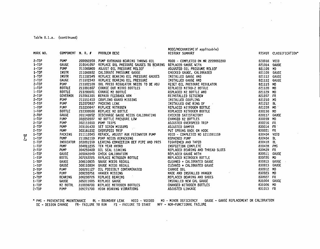
Table B.1.a. (continued)
MODE/MECHANISM(if applicable)HISTORY SUMMARYMARK NO. COMPONENT M. R. # PROBLEM DESC RTSVDT CLASSIFICATION*
2-TDP1-TOP1-TOP1-TDP1-TDP2-TDP2-TDP1-TDP1-TDP2-TDP2-TDP2-TDP1-TDP1-TDP2-TDP1-TDP2-TDP2-TDP2-TOP1-TOP1-TDP1-TDP1-TOP2-TDP1-TDP1-TDP1-TDP1-TDP2-TDP1-TDP2-TDP1-TOP1-TDP2-TDP
PUMPGAUGEPUMPINSTRINSTRGAUGEPUMPBOTTLEBOTTLEGOVERNORPUMPPUMPPUMPBOTTLEGAUGEPUMPPUMPPUMPPUMPPACKINGPUMPINDICATORPUMPPUMPGAUGEBOTTLGAUGEGAUGEPUMPPUMPBEARINGGAUGEN2 BOTTLPUMP
209092200 PUMP OUTBOARD BEARING THROWS OIL210141057 REPLACE OIL PRESSURE GAUGES TO BEARING211060800 ADJUST OIL PRESSURE RELIEF211060852 CALIBRATE PRESSURE GAUGE211102345 REPLACE BEARING OIL PRESSURE GAUGES211102343 REPLACE BEARING OILPRESSURE211102100 OIL PRESS REGULATOR NEEDS TO BE ADJ211091807 CHANGE OUT NITRO BOTTLES211280901 CHANGE N2 BOTTLE212061305 REPAIR FEEDBACK ARM211151410 COUPLING GUARD MISSING212070837 PACKING LEAK212230847 REPLACE NITROGEN212300500 REPLACE N2 BOTTLE301140952 DISCHARGE GAUGE NEEDS CALIBRATING302050907 N2 BOTTLE PRESSURE LOW302111050 PUMP TRIPS303101430 SET SCREW MISSING303181232 OVERSPEED TRIP,211112045 REPACK, ADJUST AUX FEEDWATER PUMP211061159 PUMP NEEDS REPACKING303091559 LEAKING CONNECTION BET PIPE AND PRES304011235 TEN YEAR HYDRO304250400 OIL SEAL LEAKING305042040 CHECK CALIBRATION307212225 REPLACE NITROGEN BOTTLE308110835 GAUGE NEEDS RECALL308110834 GAUGE NEEDS RECALL308291127 OIL POSSIBLY CONTAMINATED309200751 HANGER MISSING306200726 REPLACE BEARING305311605 REPLACE GAUGE310030700 REPLACE NITROGEN BOTTLES309271700 HIGH BEARING VIBRATIONS
VOID - COMPLETED ON MR 2209092200REPLACED GAUGE WITHADJUSTED OIL PRESSURE RELIEFCHECKED GAUGE, CALIBRATEDINSTALLED GAUGE ANDINSTALLED GAUGE ANDRESET OIL PRESSURE REGULATORREPLACED NITRO-2 BOTTLEREPLACED N2 BOTTLE ANDREINSTALLED SETSCREWINSTALLED COUPLINGINSTALLED ONE RING OFREPLACED NITROGEN BOTTLEREPLACED NITROGEN BOTTLECHECKED SATISFACTORYCHANGED N2 BOTTLESADJUSTED OVERSPEED TRIPADJUSTED DAMPERPUT SPRING BACK ON HOOKVOID - COMPLETED NO 1211061159REPACKED PUMPTIGHTENED AND TAPEDINSPECTION COMPLETEREPLACED BEARING AND THREAD SLOESREPLACED GAUGE WITHREPLACED NITROGEN BOTTLECLEANED + CALIBRATED GAUGECLEANED + CALIBRATED GAUGECHANGE OILMADE AND INSTALLED HANGERREPLACED BEARING AND SHOESINSTALLED NEW CAL GAUGECHANGED NITROGEN BOTTLESADJUSTED LINKAGE
820916821014821109821109821112821112821115821120821129821207821210821212821228830110830117830209830216830314830321830404830404830418830428830429830511830726830813830813830912830923830927831004831006831013
VOIDGAUGEMDGAUGEGAUGEGAUGEMDMDMDFRMDBLMDMDGAUGEMDFRFR'FRVOIDBLBLPMSFRGAUGEMDGAUGEGAUGEMDMDFRGAUGEMDFR
5
* PMS - PREVENTIVE MAINTENANCE BL - BOUNDARY LEAK VOID - VOIDED MD - MINOR DEFICIENCY GAUGE - GAUGE REPLACEMENT OR CALIBRATIONDC - DESIGN CHANGE FR- FAILURE TO RUN FS - FAILURE TO START NFF - NON-FUNCTIONAL FAILURE

Table B.1.a. (continued)
MARK NO.
1-TOP1-TDP1-TOP1-TDP2-TOP1-TDP1-TOP2-TDP1-TOP1-TOP1-TDP2-TOP2-TDP1-TOP2-TDP1-TOP1-TDP1-TOP
w 1-TDP,J~ 2-TOP
1-TDP2-TOP
1-TDP1-TDP
1-TDP2-TDP
1-TDP
COMPONENT
VALVEPUMPPUMPPUMPGAUGEPUMPVALVEVALVEPMP GOVPUMPPUMPSWITCHGAUGEPUMP
PUMPPUMPPUMP
PUMPPUMPPUMPPUMP
PUMPPUMP
PUMPPUMP
PUMP
M. R. #
310272330310221306310301600306200725311210152310201430401040826401040811312311328402171445403030615402240947404051830307211530406121600110291236014061
13659137111366020077
1235022684
2190323379
PROBLEM DESC
CAP LEAKINGOUTBOARD LEAKS 1-TDPREPACK PUMPOIL LEAKPLACE DAMPENER IN LINEPUMP HAS LOW DELTA PRESSURECLEAN AND GREASE VALVE STEMCLEAN AND GREASE VALVE STEMREPAIR GOVERNORREPLACE N2 BOTTLETRIP VALVE LEAKS EXCESSIVELYPUMP WILL NOT CUT OFF IN AUTOGAUGE MISSINGBEARING HAS NON-QUALIF THRUST COLLARMANUFACTURE 2 COUPLINGSREPLACE NITROGEN BOTTLEREPLACE OIL SLINGER RINGMECHANICAL LINKAGE BROKEN
REPLACE BROKEN GAUGEREPLACE PRESS GAUGE 2-TDPREPLACE BROKEN GAUGE GLASSINVEST/REPAIR SOV-MS-A/B
OUTBOARD BEARING THROWS OILREPAIR OUTBOARD BEARING SEALLEAKTIGHTEN OUTBOARD PKG GLANDPUMP INOPERABLE, REPAIR
MODE/MECHANISM(if applicable)HISTORY SUMMARY
TIGHTENED CAP ON CHECK VALVEVOID - TO BE DONE ON MR 0310301600CHECKED LEAK RATEVOIDINSTALLED FLOW OSCILLATORVOID - NOT A PROBLEMCLEANED & LUBRICATEDCLEANED & LUBRICATEDINSTALLED NEW SEATREMOVED & REPLACED BOTTLENO PROBLEMCHECKED SWITCHINSTALLED NEW GAUGEREPLACED NON QUALIFIED THRUST COLLARMANUFACTURED 6 COUPLINGSVOID - AS PER SHIFT SUPERVISOR.VOID - TO BE COMPLETED ON WO 012350.REINSERTED ROD AND CLOSED SOCKET ENDS AROUND BALLTIP.REPLACE GAUGE.REPLACE GAUGEINSTALLED NEW CALIBRATED GAUGE.BOTH VALVES ARE OPEN WITH OPEN INDICATION INCONTROL ROOM ON BOTH VALVES NO WORK PERFORMEDVOID - WORK COMPLETED ON WO 004170.REPLACED GASKET, MANUFACTURED OIL PAPER.
REPACKED PUMP, ONE-HALF PACKING USED, SHOP SPARE.REMOVED INBOARD AND OUTBOARD BEARING CAPS-FOUND BOTH JOURNAL BEARINGS IN GOOD CONDITION-OUTBOARD THRUST BEARING -THRUST SHOES- WIPED ANDROLLED OVER WITH BABBITT. ALIGNMENTVOID - NOT REQUIRED AS PER ATTACHED MEMO.
RTSVDT
831031831101831104831107831122840103840109840109840111840222840305840330840427840517840613850103850207850214
850314850314850315850620
850726850809
850809850819
CLASSIFICATION*
BLVOIDBLVOIDDCVOIDPMSPMSFRMDVOIDFRGAUGEMDPMSVOIDVOIDFR
GAUGEGAUGEGAUGEVOID
VOIDMD
BLFR
23564 INVESTIGATE/REPAIR PUMP1-TOP
851213 VOID
* PMS - PREVENTIVE MAINTENANCE BL - BOUNDARY LEAK VOID - VOIDED MD - MINOR DEFICIENCY GAUGE - GAUGE REPLACEMENT OR CALIBRATIONDC - DESIGN CHANGE FR- FAILURE TO RUN FS - FAILURE TO START NFF - NON-FUNCTIONAL FAILURE

Table B.1.a. (continued)
MODE/MECHANISM(if applicable)HISTORY SUMMARYMARK NO.
1-TDP
1-TDP2-TOP2-TOP
1-TDP
2-TDP1-TDP2-TOP
2-TDP1-TOP1-TDP
* tz
1-TOP
1-TDP
1-TDP1-TDP1-TDP
2-TDP1-TDP
COMPONENT
PUMP
PUMPPUMPPUMP
PUMP
PUMPPUMPPUMP
PUMPPUMPPUMP
PUMP
PUMP
PUMPPUMPPUMP
PUMPPUMP
M. R. # PROBLEM DESC RTSVDT CLASSIFICATION*
851213 VOID24333 INVESTIGATE/REPAIR PUMP
284622871928865
29554
284172944328172
310293227326976
27017
27016
376553355438556
1-TDPREPLACE N2 BOTTLEREPLACE NITROGEN BOTTLEADJUST PACKING GLANDS
CHANGE OUT BOTTLE
INVEST/ADJUST GOVERNOR RPMCHANGE OUT BOTTLE-I-INSPECT FOR BLOCKAGE
REPLACE NITROGEN BOTTLEVOID TO WO 031510P-REPLACE GLAND STUDS/NUTS
P-REPAIR OIL LEAKS
ADJUST/REPACK GOV VALVE
PERFORM CTS 87-86CALIBRATE/REPLACE GAUGECHECK INSTRUMENTS
VOID - NOT REQUIRED AS PER ATTACHED MEMO.
REPLACED NITROGEN BOTTLE.CHANGED OUT NITROGEN BOTTLE IAW PROCEDURE.TIGHTENED OUTBOARD GLAND ONE FLAT LEAK STOPPED100%. TIGHTENED INBOARD END 3 FLATS LEAK DECREASEDTO 20 DROPS PER MIN.REMOVED EMPTY BOTTLE, INSTALLED NEW BOTTLE(210oPSI), CHECKED FITTINGS FOR LEAKS. TESTEDSATISFACTORY.VOID NO PROBLEM DURING PTVOID - WORK PERFORMED ON EMERGENCY WO 029544.REMOVED OIL COOLER FROM SYSTEM TESTED FORBLOCKAGE. NO BLOCKAGE FOUND. REINSTALLED IN SYSTEMREPLACE NITROGEN BOTTLEVOID - COMPLETED ON WO 031510.PACKING LEAK/NORMAL WEARUNCLOGGED DRAIN LINES, REPLACED PACKING GLANDSTUDS, REPACKED INBOARD SIDE OF PUMP. 4 RINGS OFPACKING USED. SHAFT SLEEVE IS WORN.BAD BEARINGS/INSUFF. OIL FLOWREPLACED BEARINGS. THRUST BEARINGS, AND REPACKEDPUMP.INSPECTED GOVERNOR. STEM IS SEALED BY LEAKOFF-CHANNELS, NO ADJUSTMENT AVAILABLE. VALVE TO BEOVERHAULED ON WR 352517.VOID - NOT REQUIRED.REPLACED GAUGE.OUT OF CAL/TIME & USE.GAUGES WERE EACH: OIL PRESSURE, 1 OIL TEMP, 1PUMP SUCTION, I PUMP DISCHARGE, AND 1 STEAMPRESSURE.VOID WORK NOT REQUIREDBROKEN PART INTERNAL/OVER PRESSURIZATIONDISASSEMBLED PUMP, REPLACED IMPELLERS, DIFUSERS,AND BEARINGS. TESTED PUMP AND RAN SATISFACTORY.
851223860102860106
860120
860121860122860224
860224860318860509
860509
860512
860627860706860715
MDPMSDC
MD
VOIDVOIDPMS
PMSVOIDBL
FR
BL
VOIDGAUGEGAUGE
21964 INVEST/REPAIR HI DISCH PRESS.38507 OVERHAUL AUX FEED PUMP
860715 VOID860718 NAF
* PMS - PREVENTIVE MAINTENANCE BL - BOUNDARY LEAK VOID - VOIDED MD - MINOR DEFICIENCY GAUGE - GAUGE REPLACEMENT OR CALIBRATIONDC - DESIGN CHANGE FR- FAILURE TO RUN FS - FAILURE TO START NFF - NON-FUNCTIONAL FAILURE NAF - NOT AN AGING FAILURE (MAINTENANCE ERROR)

Table B.1.a. (continued)
MARK NO.
1-TDP
1-TDP1-TDP1-TDP
1-TDP
1-TOP
1-TDP
1-TDP
COMPONENT
PUMP
PUMPPUMPPUMP
PUMP.
PUMP
PUMP
PUMP
PUMP
PUMP
PUMP
PUMP
PUMPPUMP
M. R. I PROBLEM DESC
38591 INVESTIGATE/REPAIR TERRYTURBINE
36784 PERFORM EWR 85-54438639 INSTALL SPOOL PIECE35392 P-OVERHAUL GOVERNOR
4170 INVESTIGATE PUMP BEARING LEAK
39823 REPLACE BEARINGS AS REQUIRED
40056 ASSIST TECH REP AS REQUIRED
40487 SPRING REPLACEMENT
40494 GOVERNOR ADJUSTMENT
41325 OPENINSPECT,REPAIR GOV VALVE
41215 ASSIST TECH REP AS REQUIRED
40454 ADJUST GOVERNOR VALVE LINKAGE
41324 ADJUST LINKAGE. HIGH DISCHARGE40488 REPAIR OVERSPEED TRIP
MODE/MECHANISM(if applicable)HISTORY SUMMARY
WORN BEARINGS/NORMAL USEDISASSEMBLED WORN BEARINGS, AND REPLACED WORNJOURNAL BEARINGS (.060).REMOVED PIPING AND INSTALLED 3-1/2 PIPE PLUGS.REMOVED TRAINER FROM PIPE. REINSTALLED PIPE.VOID - WORK WAS PERFORMED ON TURBINE AND MOTOR. NOPROBLEM FOUND WITH GOVERNOR VALVE.BROKEN SLINGER/THRUSTINGREPLACED SLINGER, BEARINGS, WEAR RINGS, BALANCEWIPED THRUST SHOES/IMPROPER SET THRUSTUNCOUPLED PUMP, TOOK ALIGNMENT CHECK AND CHECKEDTHRUST. REMOVED BEARING HOUSING OUTBOARD THAT WASFOUND INBOARD.ASSIST TECH REP VERIFIED PROPER LINKAGESETTINGS ON GOVERNOR LINKAGE.GOVERNOR VALVE NOT OPEN ALL THE WAY, SUSPECT BADSPRING. REMOVED OLD SPRING AND REPLACED WITH NEWSPRING. OPS DID AN OPERABILITY TEST AND GOVERNORVALVE IS STILL NOT OPENING.REMOVED BONNET AND ROTATED 90 DEGREES TO PUT FLATMACHINED SURFACE TO NORTH POSITION. READJUSTEDLINKAGE AND TEST RAN PUMP.VALVE GOV LEAK THRU/STEAM CUT SEATSREMOVE LINKAGE AND VALVE FORM SYSTEM. FOUND BODYTO BE STEAM CUT ON SEATS. AS WE REMOVED BUSHINGTEST RAN PUMP IAW OPS PT. TEST SAT, NO REPAIRREQUIRED 9/24/86LINKAGE/IMPROPER SETDISCONNECTED LINKAGE L2 AND LI, REMOVED PIN FROMSHAFT LI. SET STEAM GOVERNOR VALVE, LOOSENEDFISHER REGULATING SPRING AND SET AT 3/8.VOID - COMPLETED ON WO 041325.VALVE CHECKED FOR FREEDOM OF MOVEMENT. FOUND TO BESTICKING APPROXIMATELY 50% IN THE CLOSED POSITION.VALVE DISASSEMBLY REVEALED HEAVY WEAR AND SOMESTEAM CUTS TO GUIDE.
RTSVDT CLASSIFICATION*
860718 NAF
860721860721860807
860820
860821
860828
860907
PMSPMSVOID
FR
NAF
PMS
FR
W 1-TDP 860907 MD
860927 FR1-TDP
2-TDP
1-TDP
1-TDP1-TDP
860929
860930
PMS
FR
860930 VOID860930 FR
* PMS - PREVENTIVE MAINTENANCE BL - BOUNDARY LEAK VOID - VOIDED MD - MINOR DEFICIENCY GAUGE - GAUGE REPLACEMENT OR CALIBRATIONDC - DESIGN CHANGE FR- FAILURE TO RUN FS - FAILURE TO START NFF - NON-FUNCTIONAL FAILURE NAF - NOT AN AGING FAILURE (MAINTENANCE ERROR)

Table B.1.a. (continued)
MARK NO.
I-TOP
2-TDP
1-TDP
1-TDP
1-TDP2-TDP
2-TDP
by 2-TOP
2-TDP
2-TDP
2-TDP
2-TDP
1-TOP
1-TDP1-TDP
COMPONENT
PUMP
PUMP
PUMP
PUMP
PUMPPUMP
PUMP
PUMP
PUMP
PUMP
PUMP
PUMP
PUMPPUMP
M. R. # PROBLEM DESC
40491 VALVE LINKAGE ADJUSTMENT
38609 REFURBISH ROTATING ASSY.
40418 INVESTIGATEREPAIR T/T VALVE
41217 ASSIST TECH REP AS REQUIRED
39931 BEARING REPAIR44339 2-TDP EWR 86-452
26975 REPLACE PCKG GLND BOLTS
44993 OVERHAUL GOVERNOR VALVE
41408 -P. L- OVERHAUL TURBINE
46180 TEST CASING SENTINEL VALVE
41407 -P- OVERHAUL PUMP
47554 CHANGE OIL
40126 REPAIR/REPLACE GOVERNOR VALVE41624 PACKING REPLACEMENT/REPAIR
MODE/MECHANISM(if applicable)HISTORY SUMMARY
WE FOUND THE LINKAGE OUT OF ADJUSTMENT ANDGOVERNOR LEVER HAD EXCESS WEAR. WE REMOVED THE OLDLINKAGE AND GOVERNOR LEVERS,REPLACING SAME WITHNEW LEVERS. THE NEW LEVERS HADROTOR ASSY. HAS BEEN REFURBISHED AND IS LOCATEDIN THE WAREHOUSE.INSPECT/INSPECT STRAINERREMOVED VALVE FROM SYSTEM, CLEANED SEATING ANDGASKET SURFACES. FOUND GASKET SURFACE STEAM CUT,WELD REPAIRED STEAM CUT.ASSISTED TECH REP IN RUNNING PUMP AND MAKING MINORADJUSTMENTS.VOID - NOT REQUIRED AS PER ENGINEER.TFE IN TWO DRAIN LINES INTO TURBINE CASING WHEREAN EXISTING PLUG IS NOW. WELD CONDENSATE POTS INEXHAUST STEAM TURBINE.REMOVED OLD STUDS AND NUTS. INSTALLED NEWSTUDS AND NUTS PUMP REPLACED UNDER WO 041407LEAKS/WEARREMOVED GOVERNOR VALVE FROM TURBINE. BOTH SEATSWERE BAD AND HAD TO BE REPLACED. REPLACED PLUGAND STEM. REPLACED FLANGE GASKETS.OVERHAUL/WEAR.REMOVED LAGGING AND UNCOUPLED TURBINE FROM PUMP.REPLACED ALL BEARINGS AND BUSHINGS ON TURBINE.REMOVED WHEEL AND FOUND IT TO BE WORN.TEST/OVERHAUL.REMOVED VALVE FROM SYSTEM AND TRANSPORTED TOINSTRUMENT SHOP CAL. LAB. SET UP ON TEST STANDAND VALVE STARTED LIFTED AT 2 PSI ADJUSTED TOREMOVED OLD ROTATING ASSEMBLY FOUND THRUST BRGWIPED-ONE SET OF SHOES WRONG FOR SIDE USED,OUTBOARD BEARINGS WORN FROM THRUST BRGDRAINED OIL FROM RESEVOIR. REMOVED COVER PLATE,WIPED OUT WITH LINT FREE DIAPER AND REFILLED WITHNON-PARFIL TURBINE OIL APPROX 17 GALS.VOID - WORK PERFORMED UNDER WO 055496.VOID - PUMP PERFORMED SATISFACTORY ONVOID - NO LEAK AS PER WALKDOWN.
RTSVDT CLASSIFICATION*
860930 FR
861001
861005
861008
861114861131
861201
861201
PMS
BL
PMS
VOIDDC
MD
PMS
861201 PMS
861203 PMS
861211 PMS
861229 PMS
861230 VOID861230 VOID
* PMS - PREVENTIVE MAINTENANCE BL - BOUNDARY LEAK VOID - VOIDEDDC - DESIGN CHANGE FR- FAILURE TO RUN FS - FAILURE TO START
MD - MINOR DEFICIENCY GAUGE - GAUGE REPLACEMENT OR CALIBRATIONNFF - NON-FUNCTIONAL FAILURE

Table B.1.a. (continued)
MARK NO.
2-TOP2-TOP
1-TOP1-TDP1-TOP1-TDP
1-TDP
1-TOP
1-TDP
COMPONENT M. R. #
PUMP 45013PUMP 48794
1-TDPw
t~.)
PUMPPUMPPUMPPUMP
PUMP
PUMP
PUMP
PUMP
PUMP
PUMP
PUMP
PUMP
PUMP
44576490604055749601
44074
51012
52935
PROBLEM DESC
IMPLEMENT BWR 86-452-P- REPR/REPL CONNECTING ROD
REFURBISH ROTATING ASSEMBLYP-REPLACE END BELL GASKETVALVE REPLACEMENTREPLACE OIL COOLER FLANGEGASKETREPLACE SIGHT GLASS
INSTALL COUPLING GUARD
REPAIR LEAK
MODE/MECHANISM(if applicable)HISTORY SUMMARY
VOID TO 44339UNIT 2-FW-T-2 OVERHAULED DURING 1986 REFUELINGOUTAGE. OVERSPEED TEST WAS PERFORMED DEC 1986SATISFACTORILY. INSPECTED LINKAGE WITHVOID - WORK ORDER CREATED TO OBTAIN PARTS ONLY.VOID - NOT LEAKING AS PER OPS RUN.VOID - TO 049601LEAK/WEARMANUFACTURED NEW GASKET AND INSTALLED ON COOLER.BROKEN SIGHT GLASS/ACCIDENTREMOVED OLD SIGHT GLASS THAT WAS BROKEN. DRAINEDOIL OUT OF SUMP AND CLEANED, QC. CLOSED OUT.REPLACED SIGHT GLASS.NO FAILURE. INSTALLED COUPLING GUARD. CHECKEDTO BE SURE COUPLING WILL NOT RUB WHEN ROTATING.MACHINERY HAS BEEN FRESHLY PAINETED. NO LEAK,PAINTERS WERE STILL PAINTING ON MACHINERY. PAINTHAS SEALED PREVIOUS LEAK.OIL LEAKAGE/LOOSE CAPFOUND UNION WAS NOT LEAKING. THE CAP ON A 3/4-CHECK VALVE LEADING TO THE SUCTION SIDE OF THELUBE OUL PUMP WAS LEAKING. TIGHTENED.INSTALLED VENT LINE AND VALVE IN THE EMERGENCYWATER SUPPLY LINE CONNECTING THE FIRE PROTECTIONMAIN TO THE SUCTION LINES OF THE AUX FW PUMPS.INSTALLED DRAINS ON UNIT 1 TURBINE DRIVER AUXFW PUMP FOR STEAM EXHAUST, STEAM RING AND TURBINECASING.INSTALLED VENTS AND VALVE IN THE EMERGENCY WATERSUPPLY LINE CONNECTING THE EMERGENCY MAKE-UP TANKTO THE SUCTION LINES OF THE AUX FW PMPS.INSTALLED A VENT ON THE FIRE PROTECTION SYSTEMSUPPLY HEADER 6- WCMU-108-151CHECKED GAGE. GAGES WAS IN CAL. AND HAD A STICKERNO FURTHER WORK REQUIRED.
870207870207870220870302
870304
870316
870526
RTSVDT CLASSIFICATION*
870205 VOID870225 PMS
1-TDP
1-TDP
1-TDP
2-TDP
2-TDP
54171 TIGHTEN/REDOPE FITTING
48005 1-TDP, EWR 86-553
48003 1-TDP ADD DRAIN LINES
48004 1-TDP EWR 86-554
VOIDVOIDVOIDBL
MD
MD
BL
870615 MD
870716 DC
870716 DC
870716 DC
44338
56858
2-TDP EWR 86-443
CAL/REPLACE GAUGE
870716
870918
DC
GAUGE
* PMS - PREVENTIVE MAINTENANCE BL - BOUNDARY LEAK VOID - VOIDED MD - MINOR DEFICIENCY GAUGE - GAUGE REPLACEMENT OR CALIBRATIONDC - DESIGN CHANGE FR- POTENTIAL FAILURE TO RUN FS - FAILURE TO START NFF - NON-FUNCTIONAL FAILURE

Table B.1.b. MAINTENANCE RECORDS FOR THE AUXILIARY FEEDWATER SYSTEM MOTOR DRIVEN FEED PUMPS
MODE/MECHANISM(if applicable)HISTORY SUMMARYMARK NO. COMPONENT M. R. # PROBLEM DESC RTSVDT CLASSIFICATION*
2-MDP-A2-MDP-B2-MDP-A2-MDP-B2-MDP-B2-MDP-A2-MDP-B2-MDP-A2-MDP-A2-MDP-A2-MDP-B2-MDP-B2-MDP-B2-MDP-A2-MDP-B1-MDP-A1-MDP-B1-MDP-B2-MDP-A2-MDP-B1-MDP-B1-MDP-A1-MDP-A2-MDP-A2-MDP-B1-MDP-B1-MDP-A2-MDP-A2-MOP-B2-MDP-A2-MDP-B1-MDP-B2-MOP-A1-MDP-A
PMP MTRPUMPPUMPPMP MTRPUMPPMP MTRPUMPPUMPPUMPPUMPPUMPPUMPPUMPINSTRINSTRPUMPPUMPPUMPPMP MTRHXPUMPPUMPPUMPPUMPPMP MTRINSTRHXINSTRINSTRPUMPPUMPPUMPINSTRPUMP
80309135420170210
80403093680309135580406145090126180090205013790205013090213132790109143780908061090109143880508034290306111690306111590703054590703054690603050090211154590108140010162020
910030700910212130910230640911042204912071559912211400
10407451040746
9110507251160213130130520207153011545
CHANGE OILHEADBOLTS 1 2 AND 1 6 LEAKLUBE OIL RES LEVEL INDICATOR BROKECHANGE OILCOUPLING GUARD MISSINGREMOVE HEAT LAMPSPUMP START NOT SATISFACTORYPUMP START NOT SATISFACTORYOIL COOLER END BELL CRACKEDREPACK INBOARD AND OUTBOARD GLANDSHEAD BOLT LEAKS-NOS. 8. 12, 15, 16, 19REPACK INBOARD AND OUTBOARD GLANDSCASING BOLTS 2. 3. 5 E SIDE 2 W SIDECHECK ON 6-1-79CHECK ON 6-1-79REPACK PUMPREPACK PUMPSEALS THROW WATERMOTOR HEATER NOT WORKINGREPAIR HEATERSREBUILD SPARE ROTATING ELEMENTOIL SUMP LEVEL INDICATOR IS BROKEREPLACE PACKINGREPACK PUMPNO LEAK OFF THRUST BEARING & PACKINGINSTALL NEW GAUGETUBE LEAKREPLACE OIL PRESS GAUGESREPLACE OIL PRESS GAUGESOUTBOARD PUMP PACKING BURNED UPREPLACE START SWITCHOIL PRESSURE GAUGESWITCH STICKSNO-LOAD AMPS
CHANGED OIL AND CHECKED BEARINGSINSTALLED SEALANT MATERIALINSTALLED DIPSTICK ARRANGEMENTCHANGED OIL AND REPLACED BEARINGREINSTALLED GUARDREMOVED HEAT LAMPSTIME DELAY TESTED SATISFACTORYTIME DELAY TESTED SATISFACTORYREPAIRED COOLERREPACKED GLANDSPERFORMED PREVENTATIVE MAINTENANCEVOIDVOIDRESET AND TESTED AGASTATRESET AND TESTED AGASTATSREPACKED PUMPREPACKED PUMPADJUSTED PACKINGINSTALLED NEW HEATERS - TESTED SATINSTALLED NEW HEATERS - TESTED SATVOIDADJUSTED FLOAT VALVEREPACKED INBOARD PACKING BOXREPAIRED PUMPADJUSTEDINSTALLED NEW GAUGECOMPLETED REPAIRSCHECKED CAL AND REPLACED GAUGESCHECKED CAL AND REPLACED GAUGESREPACKEDTESTED SATGAUGE CHECKED SATSWITCH OPERATIONALPI CURVE SAT
780330780330780404780406780407790129790207790209790324790324790430790502790511790619790621790709790710790720790910790910791002791003791021791031791106791211791223800106800106800128800128800131800211800318
PMSBLMDPMSMDDCFSFSFRBLBLVOIDVOIDPMSPMSBLBLBLFSFSVOIDMDBLBLMDGAUGEFRGAUGEGAUGEMDMDGAUGEMOPMS
w
* PMS - PREVENTIVE MAINTENANCE BL - BOUNDARY LEAK VOID - VOIDED MD - MINOR DEFICIENCY GAUGE - GAUGE REPLACEMENT OR RECALIBRATIONDC - DESIGN CHANGE FR- FAILURE TO RUN FS - FAILURE TO START

Table B.1.b. (continued)
MODE/MECHANISM(if applicable)HISTORY SUMMARYMARK NO. COMPONENT M. R. # PROBLEM DESC RTSVDT CLASSIFICATION*
1-MDP-B2-MOP-A2-MDP-B1-MDP-A2-MDP-A1-MOP-A2-MDP-A1-MOP-B2-MDP-B2-MDP-B2-MDP-B1-MDP-A2-MDP-A1-MDP-A1-MOP-B2-MDP-B1-MDP-A1-MOP-A1-MDP-A1-MDP-B1-MDP-A1-MDP-A1-MDP-B2-MDP-B2-MDP-A1-MDP-B1-MDP-A1-MDP-B1-MDP-B1-MDP-A1-MDP-B1-MDP-B1-MDP-B1-MDP-A
PUMPINSTRPUMPPUMPPUMPPUMPVALVEPMP MTRPUMPVALVEINSTRPUMPPUMPHXHT EXCHPUMPPUMPPUMPPUMPPUMPHXPMP MTRPMP MTRINSTRVALVEPUMPPUMPPUMPPMP MTRPUMPINSTRPMP MTRPMP MTRPMP MTR
30115464120800
9121815005020510418073252904476181100715151072221554161555
1101052312270930
101080715101130847101130846101080714101291401101291403101291402101291404101311306
8271712102011220102080500102111630102091230
711090971109128271711
103102255103050933
12112345103121811102270714
NO-LOAD AMPSGAUGE BROKENSPLIT CASING IS LEAKING ON PUMPOIL LEAK ON INBOARDOUTBOARD PACKING LEAKVENTILATION SHIELD MISSING ON MOTORREPAIR HANDWHEEL AND STEMWRONG OIL IN REDUCTION GEARPUMP WILL NOT AUTO STARTNUT MISSING ON VALVE HANDWHEELCALIBRATEDAMAGE WAS CAUSED BY FREEZINGSUCTION PRESSURE GAUGE MISSINGREPAIR BROKEN LUBE OIL COOLERHEAD-ON COOLER BROKENLOW OIL LEVELLUBE OIL COOLER BROKENHEAT TRACE LUBE OIL COOLERHEAT TRACE LUBE OIL COOLERHEAT TRACE LUBE OIL COOLERMANUFACTURE GASKETPERFORM PMS ON MOTORUNCOUPLE PUMP FROM MOTORREPLACE 2-MDP-B DISCHG PRESS GAUGEINSPECT VALVE DISCPERFORM MMP-FW-004PERFORM PMSPERFORM PMSPERFORM PMS ON MOTORPUMP WOULD DEVELOP NO DISCHARGE PRESSREPLACE GAUGE DEFECTIVE ON TESTINGUNCOUPLE MOTORALIGN AND COUPLE PUMP MOTORREPAIR FLEX CONDUIT
PI CURVE SATADJUSTED GAUGE POINTERVOIDINSPECTED BEARINGSINSTALLED TEFLON PACKINGSHIELD REPLACEDREPLACED GASKETCOMPLETED DRAINING AND REFILLED OILTESTED SATISFACTORYINSTALLED NUTCAL GAUGES. REPLACED SUCTION GAUGEFIXED SPLIT CASINGREPLACED MISSING GAUGE WITH CAL ONEREPLACED GASKET AT HEADREMOVED HEAD, BRAZED TOGETHEROIL LEVEL NORMALREPAIRED LUBE OIL COOLER HEADERHEAT TRACING INSTALLEDHEAT TRACING INSTALLEDHEAT TRACING INSTALLEDREMOVED HEADDISASSEMBLED AND REASSEMBLED MOTORUNCOUPLED MOTOR FROM PUMPREPLACED WITH NEW CALIBRATED GAUGEFURMANITED MANWAYPMS SERVICE WORK DONEVOID - DONE ON PREVIOUS MRVOID - DONE ON PREVIOUS MRDISASSEMBLED AND ASSEMBLED MOTOR - SATVOID.REPLACED GAUGEUNCOUPLING MOTOR FROM PUMPRECOUPLED PUMP TO MOTORMADE REPAIRS TO 1-MDP-A
800318800424800428800508800603800619800625800717800725800830801104810101810109810114810114810115810201810202810202810202810205810207810207810209810212810214810217810217810228810311810311810312810316810317
PMSGAUGEVOIDMDBLMDMDMDFSMDGAUGEFRGAUGEFRFRMDFRDCDCDCBLPMSPMSGAUGEBLPMSVOIDVOIDPMSVOIDGAUGEPMSPMSMD
4w
* PMS - PREVENTIVE MAINTENANCE BL - BOUNDARY LEAK VOID - VOIDED MDDC - DESIGN CHANGE FR- FAILURE TO RUN FS - FAILURE TO START
- MINOR DEFICIENCY GAUGE - GAUGE REPLACEMENT OR RECALIBRATION

Table B.1.b. (continued)
MODE/MECHANISM(if applicable)HISTORY SUMMARYMARK NO. COMPONENT M. R. # PROBLEM DESC RTSVDT CLASSIFICATION*
1-MDP-A1-MDP-A1-MDP-B1-MDP-A2-MDP-A1-MDP-B1-MDP-A1-MDP-B1-MDP-A1-MDP-A1-MDP-B2-MDP-A1-MDP-A2-MDP-B1-MDP-A1-MDP-B2-MDP-B1-MDP-A2-MDP-A2-MDP-B2-MDP-A2-MDP-B2-MDP-A2-MDP-A2-MDP-B2-MOP-A2-MDP-B1-MOP-B2-MDP-A2-MDP-B2-MDP-A2-MOP-A2-MDP-B2-MDP-A
PUMPPUMPPUMPPUMPVALVEINSTRGAUGEINSTRGAUGEINSTRINSTRINSTRPMP MTRPUMPPUMPPUMPINSTRPUMPPUMPPUMPMOTORMOTORMOTORPUMPPUMPPUMPPUMPPUMPPUMPPUMPPUMPPUMPPUMPTC
8271030102091231104011900104070800
6160900105030601105120750105030600105120751105220735105220737106020610121123304180731
1070907291070907291100107208122913301111215001111215021111215031111215041120922001120815301120818271122111011121505961122123001100915341100915377110906
111020615111020615112291236
REPAIR GAUGEPERFORM HMP-FW-004PACKING GLAND SPRAYING WATERPACKING LEAKS BOTH ENDSINSTALL CAPCHECK CALIBRATIONCALIBRATE GAUGE OR REPLACECHECK CALIBRATIONCALIBRATE GAUGE OR REPLACEPUMP STARTED IN 62PUMP STARTED IN 66PRESSURE INDICATOR NEEDS REPLACINGALIGN AND COUPLE MOTOR TO PUMPNO OIL PRESSURERETUBE BYPASS LINESRETUBE BYPASS LINECALIBRATE GAUGEOIL LEAK FROM INBOARD PUMP BEARINGBREAK COUPLING FOR ELECTUNCOUPLE COUPLINGRECONDITION MOTORRECONDITION MOTORMOTOR LEAKING OILCOUPLE PUMP TO MOTORCOUPLE 2-MOP-BALIGN PUMP AND MOTOROUTBOARD SHAFT SEAL ON PUMP LEAKSREPACK 38 AFPPERFORM MMP-P-FW-004PERFORM MMP-P-FW-004PERFORM PMSINSTALL HEAT TRACINGINSTALL HEAT TRACINGREPLACE T/C ON 2-MDP-A
DISASSEMBLED GAUGEPREVENTIVE MAINTENANCE SERVICE AND CADJUSTED PACKINGADJUSTED PACKINGREMOVED CHICAGO FITTING AND INSTALLEDREPLACED GAUGEREPLACED GAUGEREPLACED GAUGEREPLACED GAUGERESET AGASTATSRESET AGASTATSINSTALLED NEW GAUGEVOID - WORK COMPLETED PRIOR TO RECPACKED STUDS CHECKED OIL PRESSURECOMPLETECOMPLETECALIBRATED GAUGEVOIDCOMPLETEDCOMPLETEDVOIDVOIDFIXED OIL LEAK, SATISFACTORYRECOUPLED PUMPCOUPLEDALIGNED COUPLINGREPLACED, UNCOUPLEDCOMPLETEDVOIDVOIDVOIDINSTALLED HEAT TRACE, SATISFACTORYINSTALLED HEAT TRACE, SATISFACTORYREPLACED THERMO READING, SATISFACTORY
810323810328810403810410810418810515810515810515810515810522810522810602810611810616810925810925811006811028811114811114811116811116811210811211811211811229811229820104820105820105820106820112820112820221
GAUGEPMSBLBLBLGAUGEGAUGEGAUGEGAUGEFSFSGAUGEVOIDFRPMSPMSGAUGEVOIDPMSPMSVOIDVOIDMDPMSPMSPMSBLBLVOIDVOIDVOIDDCDCGAUGE
L
* PMS - PREVENTIVE MAINTENANCE BL - BOUNDARY LEAK VOID - VOIDED MD - MINOR DEFICIENCY GAUGE - GAUGE REPLACEMENT OR RECALIBRATIONDC - DESIGN CHANGE FR- FAILURE TO RUN FS - FAILURE TO START

Table B.1.b. (continued)
MODE/MECHANISM(if applicable)HISTORY SUMMARYMARK NO. COMPONENT M. R. # PROBLEM DESC RTSVDT CLASSIFICATION*
2-MDP-A2-MDP-B1-MDP-B2-MDP-B2-MDP-B1-MDP-A1-MDP-B1-MDP-B1-MDP-B1-MDP-A1-MDP-B2-MDP-B2-MDP-A1-MDP-A2-MDP-A2-MDP-A1-MDP-B2-MDP-B1-MDP-A1-MDP-A1-MDP-B1-MDP-A2-MDP-A1-MDP-B1-MDP-B2-MDP-B2-MDP-B2-MDP-A1-MDP-A1-MDP-A1-MDP-B1-MDP-B1-MDP-A1-MDP-B
MOTORMOTORPUMPPUMPPUMPMOTORMOTORPUMPPUMPPUMPPUMPINSTRMOTORMOTORPUMPPUMPPUMPPMP MTRGAUGEPUMPGAUGEINSTRINSTRPUMPPUMPVALVEVALVEGAUGEPUMPVALVEVALVEPUMPPUMPPUMP
203050957203050956111110340202090532202090531203200519203110845203130335203092235203261300204110408206200426206022605206022599208020025209011502209110240210101905210141054210050528210141056211102352211102348212071150212071930212070836212070835212141458302102307302141430302141431304110429304011411304011433
BRIDGE MEGGER & RUN PI CURVEBRIDGE MEGGER & RUN PI CURVEBEARING VIBRATION PUMPNO GUARD ON COUPLINGCASING LEAKMOTOR WAS SPRAYED WITH STEAMUNCOUPLE PUMPEXCESSIVE VIBRATION PUMPINBOARD BEARING HAS HIGH VIBRATIONDETERMINE FAILURE OF PUMPHIGH VIBRATION POINT 15.1BOIL LEVEL GAUGE HAS BEEN REMOVEDFW-SV-E/A1FW-SV-E/A1COVER MISSING - REPLACECOUPLING GUARD MISSING, REPLACEBEARING ON PUMP IS LEAKINGBRIDGE MEGGAR PI CURVE MOTORREPLACE OIL PRESSURE GAUGESFW LEAK UPSTREAM OF LUBE OIL COOLERREPLACE OIL PRESSURE GAUGESCALIBRATE BEARING OIL PRESSURECALIBRATE BEARING OIL PRESSUREREPACK PUMPPUMP NEEDS TO BE REPACKEDPACKING LEAKPACKING LEAKINSTALL GAUGEINBOARD PACKING NEEDS ADJUSTEDVALVE EXTREMELY HARD TO CYCLEVALVE EXTREMELY HARD TO CYCLEINBOARD GLAND HAS EXCESSIVE LEAKAGETEN YEAR HYDROTEN YEAR HYDRO
BRIDGED & MEGGERED MOTOR 820305 PMSBRIDGED & MEGGERED MOTOR 820305 PMSREPLACED INBOARD BEARING 820309 FRINSTALLED COUPLING GUARD 820311 MDTIGHTENED BOLTING 820311 BLPERFORMED PI CURVE 820320 FSVIBRATION RODS INDICATE MOTOR/DKP, SAT 820322 PMSVOID - HOLDING PREVIOUS MR 820323 VOIDVOID 820324 VOIDBREAKER CLOSED SATISFACTORY 820330 FSOBSERVED IRD VIBRATION 820517 PMSNO REPAIR NEEDED 820628 VOIDPERFORMED PMS 820703 PMSPERFORMED PMS 820704 PMSREPLACED COVER 820825 MDFOUND COUPLING GUARD 820913 MDTIGHTENED UP BOLTS AND 820920 MDPI CURVE SATISFACTORY 821010 PMSREPLACED GAUGE WITH 821014 GAUGEREPAIRED LEAK ON 3/4 PIPE 821014 FRREPLACED GAUGE WITH 821014 GUAGEINSTALLED NEW GAUGES 821112 GAUGEINSTALLED NEW GAUGES 821112 GAUGEADDED PACKING 821207 BLVOID - WORK DONE ON 1212071150 821208 VOIDINSTALLED 7 RINGS OF PACKING 821212 BLADJUSTED VALVE PACKING GLAND 821212 BLREPLACED MISSING 821216 GAUGEADJUSTED PACKING 830216 BLVOID OPERATOR LUBRICATED THE VLV 830217 VOIDVOID OPERATOR LUBRICATED THE VLV 830217 VOIDADJUSTED PACKING 830420 BLINSPECTION COMPLETE 830428 PMSINSPECTION COMPLETE 830428 PMS
MD - MINOR DEFICIENCY GAUGE - GAUGE REPLACEMENT OR RECALIBRATION* PMS - PREVENTIVE MAINTENANCE BL - BOUNDARY LEAK VOID - VOIDEDDC - DESIGN CHANGE FR- FAILURE TO RUN FS - FAILURE TO START

Table B.1.b. (continued)
MODE/MECHANISM(if applicable)HISTORY SUMMARYMARK NO. COMPONENT M. R. / PROBLEM DESC RTSVDT CLASSIFICATION*
1-MDP-B1-MDP-A1-MDP-A2-MDP-A2-MDP-B1-MDP-A1-MDP-B2-MDP-A2-MOP-B2-MDP-A2-MDP-B2-MOP-A2-MDP-A2-MDP-B2-MDP-A2-MDP-B2-MDP-A2-MDP-A1-MDP-A1-MDP-B2-MDP-B1-MDP-B2-MOP-A2-MDP-A2-MDP-B2-MDP-B2-MDP-B1-MDP-A1-MDP-A1-MDP-B2-MDP-A2-MDP-B1-MDP-A1-MOP-A
GAUGEVALVEBOLTMOTORMOTORBREAKERPUMPPUMPPUMPVALVEMOTORPUMPPUMPBREAKERMOTORPUMPMOTORELAYGAUGEGAUGEGAUGEPUMPPUMPGUARDVALVEPUMPGAUGEBOLTVALVEVALVEVALVEVALVEMOTORPUMP
304271100305011737302112151305060227305060230306072125306110230304020343304020342307080532306021043308091500306080928306241524306021042306080929309211500310060105310201508310201507310201557310221305310300751310280742311071146309041254311292204312040340401040828401040832401040815401030818304041600403030100
DISCH PRESS GAUGE NEEDS TO BE CALIVALVE COUPLING1ST BOLT INBOARD ON TOP LEAKSINSTALL WIRE MESH SCREENS ON MOTORINSTALL WIRE MESH SCREWSRELAY DROP ON A PHSE INSTLUBE OIL LEAK ON OIL COOLERREPLACE PLASTIC PLUGS ON MOTORREPLACE PLASTIC PLUGS ON MTRPACKING LEAKDISCONNECT AND RECONNECTDAMPEN THE PULSATIONS TO GAUGEUNCOUPLE PUMPINSP ELEC INTERLOCKSDISCONNECT + RECONNECTUNCOUPLE PUMPREPAIR OR REPLACE MOTOR HEATERREPLACE 2-MDP-A RELAYLOCAL LEVEL GAUGE DOESN'T WORKLUBE OIL RESERVOIR DOESN'T WORKFIX OR REPLACE LUBE OIL GAUGEINBOARD SEAL LEAKS 1-MDP-BINSTALL COUPLING COVERREINSTALL COUPLING GUARDPACKING LEAKINBRD + OUTBRD PMP SEALS LEAKCALIBRATE DISCHARGE PRESSURE GAUGECASING BOLT IS CRACKEDCLEAN AND GREASE VALVE STEMCLEAN AND GREASE VALVE STEMCLEAN AND GREASE VALVE STEMCLEAN AND GREASE VALVE STEMDISCONNECT MOTORADJUST PACKING
REPLACED GAUGEREPLACED VARIOUS LEAKING FITTINGSREPLACED GASKET ANDINSTALLED SCREENSINSTALLED SCREENSMOTOR BRIDGED + MEGGEREDTIGHTENED LUBE OILNO PLUGS NEEDEDNO PLUGS NEEDEDADJUSTED PACKING GLANDDISC + INSPECT BEARINGSINSTALLED VIBRATION DAMPENERSALIGNED AND COUPLED PUMPINSPECTED INTERLOCKSDISASSEMBLE INSPECT REASSEMBLERECOUPLED PUMPREPLACED HEATERREPLACED RELAY COIL FAILEDCLEANED UP LEVEL GAUGECLEANED UP LEVEL GAUGECLEANED UP LEVEL GAUGEADJUSTED PACKINGVOID - TO BE COMPLETED ON 0310280742INSTALLED COUPLING GUARDADJUSTED PACKING GLANDVOIDCHECKED CALIBRATION OF GAUGEDETORQUEDCLEANED & LUBRICATEDCLEANED & LUBRICATEDCLEANED & LUBRICATEDCLEANED & LUBRICATEDVOID-COMPLETED ON MR 1307012547ADJUSTED PACKING GLAND
830428830511830525830531830531830611830621830710830710830724830730830811830815830815830822830906831006831012831027831027831027831029831101831102831111831202831205831209840109840109840109840109840118840303
GAUGEBLBLMDMOFSMDVOIDVOIDBLPMSDCPMSPMSPMSPMSFSFSMDMDMDBLVOIDMDBLVOIDGAUGEMDPMSPMSPMSPMSVOIDBL
-J
* PMS - PREVENTIVE MAINTENANCE BL - BOUNDARY LEAK VOID - VOIDEDDC - DESIGN CHANGE FR- FAILURE TO RUN FS - FAILURE TO START
MD - MINOR DEFICIENCY GAUGE - GAUGE REPLACEMENT OR RECALIBRATION

Table B.I.b. (continued)
MARK NO.
2-MDP-B2-MOP-B1-MDP-A1-MDP-B1-MDP-A2-MOP-A2-MDP-B1-MDP-B2-MDP-B2-MOP-A2-MDP-B1-MDP-A1-MDP-B1-MDP-A
1-MDP-A
1-MDP-A
2-MDP-B2-MOP-B2-MDP-A1-MDP-A
COMPONENT
MOTORPUMPVALVEPUMPPUMPPUMPPUMPPUMPPUMPPUMPVALVEPUMPPUMPPUMP
PUMP
PUMP
PUMPPUMPPUMPPUMP
PUMP
PUMP
PUMP
M. R. #
3083106004040115134041412004050815164050815154050815364050815354071614003111610404080107233120705095707570610303
10304
10300
11952027030308813467
PROBLEM OESC
PLACE SIGHTGLASS ON OUTBRD MTRREPACK PACKING GLANDBODY TO BONNET LEAKINSPECT INSULATION AT MOTORINSPECT INSULATION AT MOTORINSPECT INSULATION AT MOTORINSPECT INSULATION AT MOTORCOUPLE BOLTS/NUTS CROSS THREADEDREPLACE OUTBOARD BEARING SIGHT GLASSREPLACE BREAKER SPRING/COTTER PINBROKEN STEMUNCOUPLE AND RECOUPLEUNCOUPLE/RECOUPLEINBOARD PACKING LEAK 1-MDP-A
ADJUST OUTBOARD PACKING LEAK
RESERVOIR INDICATOR CAPMISSINGADJUST PACKING LEAK W/PMP RUNNREPACK PUMPPIN AND SPRING 25-14REPAIR/REPLACE OIL SIGHT GLASS
MODE/MECHANISM(if app1icable)HISTORY SUMMARY
VOID COMP ON MR2311161040REPACKED PUMPINSTALLED NEW SEAL RINGADDED INSULATION TO MOTOR LEADS FORINSPECTED LEADS TAPED FORINSPECTED MOTOR LEADS TAPED FORINSPECTED AND TAPED MOTOR LEADSREPAIRED COUPLING GUARD ANDCHECK FOR LEVEL GAUGEVOID - COMPLETED ON WO 003088VOID - TO BE COMPLETED ON WO 001471VOID - WORK NOT TO BE PERFORMED THIS OUTAGE.VOID - WORK NOT TO BE PERFORMED THIS OUTAGE.ADJUSTED INBOARD PACKING GLAND 1 FLAT ON GLANDNUTS.ADJUSTED OUTBOARD PACKING GALND 1 FLAT ON GLANDNUTS.NEED CAP IN ORDER TO FIX. CAPS ALL IN PLACE ON AUXFEED PUMPS.ADJUSTED PACKINGVOID--NO PROBLEM EXISTS.VOID TO BE COMPLETED ON WO 12924REPLACE SIGHTGLASS TUBE 1/2-X2 LONG SIGHT GLASSUSED FROM PIECE IN SPARE PARTS CAGE IN MACHINESHOP.WORK PERFORMED BY AUTOMATION AND CONTROL.FOUND TRIP FUSES 25A5/25A6 PULLED CAUSING2-MOP-A NOT TO AUTO START WHEN REQUIRED.WORK PERFORMED BY AUTOMATION CONTROL/FOUND TRIPFUSES FOR 2585/2506 PULLED CAUSING 2-MDP-B NOTTO AUTO START WHEN REQUIRED 5/10/85.REMOVED BAD HEATER FROM MOTOR -NO STOCK ITEM-HEATER ORDERED 3/25/85. REPLACED DEFECTIVEHEATER, TEST SAT.
RTSVDT
840403840403840417840514840517840517840517840727840809840811840817841113841113841207
841207
850118
850107850301850306850312
CLASSIFICATION*
VOIDBLBLPMSPMSPMSPMSMDMDVOIDVOIDVOIDVOIDBL
BL
MD
BLVOIDVOIDMD
00
2-MOP-A
2-MOP-B
2-MDP-B
20053 INVEST/REPAIR PUMP 2-MDP-A
20076 2-MDP-B NO AUTO START
15531 2-MOP-B CHECK HEATERS
850517 NAF
850620 NAF
850712 FS
* PMS - PREVENTIVE MAINTENANCE BL - BOUNDARY LEAK VOID - VOIDED MD - MINOR DEFICIENCY GAUGE - GAUGE REPLACEMENT OR RECALIBRATIONDC - DESIGN CHANGE FR- FAILURE TO RUN FS - FAILURE TO START NAF - NOT AN AGING FAILURE (MAINTENANCE ERROR)

Table B.1.b. (continued)
MARK NO.
2-MDP-A1-MDP-A
1-MOP-A1-MDP-B
1-MDP-B1-MDP-B
2-MOP-B
2-MDP-B
w 1-MOP-BI'0
2-MDP-A2-MDP-A
2-MDP-A2-MDP-B
1-MDP-B
1-MDP-A
COMPONENT
PUMPPUMP
PUMPPUMP
PUMPPUMP
PUMP
PUMP
PUMP
PUMPPUMP
PUMPPUMP
PUMP
PUMP
M. R. # PROBLEM DESC
01077 10 YR ISI HYDRO TEST AF PUMP13371 REPAIR INBOARD/OUTBOARD
LEAKAGE
6020 1-MDP-A CHANGE BEARINGS6019 1-MDP-B
DISCONNECTINSPECT,RECONNECT23128 UNCLOG DRAIN LINE 1-MDP-B23127 ADJUST PACKING/REMOVE EDCTR ON
PUMP CSG
27629 REPAIR EXCESS INBOARD VIBRATIONS
28864 ADJUST PACKING GLANDS
26260 REPACK PUMP
28853 ADJUST PACKING GLANDS26971 REPLACE PKG BLND BOLTS
MODE/MECHANISM(if applicable)HISTORY SUMMARY
VOID-WORK NOT REQUIREDRAN PUMP. NEEDED REPACKING. REMOVED PACKING INBD/OUTBD ENDS. CLEAN/INSPECT GLAND STUDS NUTS WASHERSSHAFT SLEEVE CONDITION AS PER PROCEDURE. REPACKEDWITH NEW PACKING WITHVOID - NOT REQUIRED.VOID - NOT REQUIRED.
DISCONNECTED LINE AND BLEW OUT WITH AIR HOSE.ADJUSTED OUT BOARD END. REMOVED PIPING. CAPED2 OPEN HOLES WITH 1/2 PIP CAPS 3/4 WROSUBMITTED TO REPACK.OPS RAN PUMP WITH DISCHARGE CLOSE AND RECEIVEDHIGH VIBRATIONS ON INBOARD BEARING. SHIFTSUPERVISOR WANTED TO PULL COUPLING GUARD ANDINSPECT COUPLING.THE PACKING HAS A FREE FLOW LEAK-OFF, ANADJUSTMENT TO A DRIP WILL CAUSE THE STUFFINGBOX TO OVERHEAT LEFT AS IS.LEAK MECHANISM/WORN PACKINGREMOVED OLD PACKING, INSTALLED NEW 1/2 - GARLOCKPACKING. ADJUSTED WITH PIMP RUNNING SAT.VOID COMPLETED ON WO 26971.CLEANED OUT CATCH BASIN, DISCONNECTED LINES,CLEANED DIRT FROM THEM AND RECONNECTED.DRAIN CLOGGED/DIRTOIL ADDED 5/6/86 OUTBOARD BEARING AMER. IND 58 OILOIL ADDED IN OUTBOARD BEARING 5/6/86 AMERICANIND 58 OIL.REPACKED PUMP AGIAN AFTER PREVIOUS PACKING HADBEEN SMOKED . PASSED PT.REMOVED TAPE AND FOUND CABLE A WAS BRAKING. WEREPLACED THE LUG AND RAYCHEM ALL THREE OF THELEADS WITH NM CK-72.
RTSVDT CLASSIFICATION*
850726 VOID850731 BL
850802850802
851015851106
VOIDVOID
MDBL
851210 NAF
860211 BL
860409 BL
860423 VOID860502 MD
3489234891
26973
37002
2-MDP-A ADD OIL2-MDP-B ADD OIL
P-REPACK PUMP
1-MDP-A EWR 86-174
860510860510
860611
860620
MDMD
BL
PMS
* PMS - PREVENTIVE MAINTENANCE BL - BOUNDARY LEAK VOID - VOIDED MD - MINOR DEFICIENCY GAUGE - GAUGE REPLACEMENT OR RECALIBRATIONDC - DESIGN CHANGE FR- FAILURE TO RUN FS - FAILURE TO START NAF - NOT AN AGING FAILURE (MAINTENANCE ERROR)

Table B.1.b. (continued)
MARK NO.
1-MDP-B
1-MDP-A
1-MDP-A
1-MOP-B
1-MDP-B
1-MDP-B
COMPONENT
PUMP
PUMP
PUMP
PUMP
PUMP
PUMP
PUMPPUMP
PUMPPUMPPUMPPUMP
PUMP
M. R. # PROBLEM DESC
37003 1-MOP-B EWR 86-174
26972 P-REPLACE GLAND BOLTS/REPACK
36782 IMPLEMENT EWR 85-544
34951 1-MDP-B REPAIR CONDUIT
36783 PERFORM EWR 85-544
38277 REPACK PUMP
35286 UNPLUG THE PUMP BASE39854 1-MDP-A MOTOR WET
39853 1-MOP-B MOTOR WET35287 ADJUST/REPACK PUMP38610 REFURBISH ROTATING ASSY.42940 REPAIR BEARING/LEAKOFF LINE
45005 2-MDP-A RAYCHEM CABLE LEADS
MODE/MECHANISM(if applicable)HISTORY SUMMARY
REMOVED ALL TAPE AND CLEANED THE CABLE WITH A-2CABLE PREPARATION KIT THEN REPLACED THE TAPE WITHRAYCHEM SPLICE KIT NM CK-IL.BAD THREADS/NORMAL WEARDO NOT NEED TO REPLACE AND SAVE STUDS AND NUTS FORENGINEERING AS PER TEL CONVERSATION. UNCLOGGEDDRAIN.REMOVE LINE FAILURE/UNNEEDEDREMOVE PIPE SUPPORT AS PER EWR FLUSH AND SUBMITSERVICE REQUEST TO REPAINT.CONDUIT BROKEN/ABUSE - SAT ONREPAIRED CONDUIT CHECKED RESISTANCE ON RTD, OK.REMOVE LINE FAILURE/UNNEEDEDREMOVE PIPE SUPPORT AND GRIND FLUSH AS PER EWR.SUBMIT SERVICE TO PAINT SURFACES.LEAKING PKG FAILURE/BURNED PACKINGREMOVED 6 RINGS OLD PACKING, REPLACED WITH 6 RINGS1/2 - GARLOCK, TEST RUN PMP PT SAT.CLEANED DRAIN LINES ON PUMP WITH A ROD.PERFORM PI CURVE ON MOTOR WINDINGS, TESTEDSATISFACTORY.PERFORMED PI CURVE ON MOTOR WINDING.VOID - COMPLETED ON WO 026972.ROTOR ASSY HAS BEEN REFURBISHED AND IS LOCATEDREMOVED OLD PACKING - 8 RINGS - AND INSTALLEDGARLOCK 98 - 7 RINGS-. INSTALLED GLAND NUTS FINGERTIGHT - SLIGHTLY SNUGGED-. TSTS RAN PUMP. ADJUSTEDPACKING GLAND SAT. LEAK OFFVOID RAYCHEM NOT NEEDED, ENG. HAS ACCEPTEDTAPE-UP.
RTSVDT CLASSIFICATION*
860620 MD
860708 MD
860710 PMS
860710
860710
MD
MD
860711 BL
0
1-MDP-A1-MDP-A
1-MDP-B1-MDP-A2-MDP-A1-MOP-B
860804860826
860826860828861001861011
MDFS
FSVOIDPMSBL
2-MDP-A 861110 VOID
* PMS - PREVENTIVE MAINTENANCE BL - BOUNDARY LEAK VOID - VOIDED MD - MINOR DEFICIENCY GAUGE - GAUGE REPLACEMENT OR RECALIBRATIONDC - DESIGN CHANGE FR- FAILURE TO RUN FS - FAILURE TO START

Table B.1.b. (continued)
MARK NO.
1-MDP-A
1-MDP-B
1-MDP-A
1-MDP-B
1-MDP-B
1-MOP-B
COMPONENT
PUMP
PUMP
PUMP
PUMP
PUMP
PUMP
PUMPPUMP
PUMP
PUMP
PUMPPUMP
PUMP
PUMP
M. R. 1 PROBLEM DESC
46435 CALIBRATE/REPLACE GAUGE
46436 CALIBRATE/REPLACE GAUGE
45559 CLEAN DRAIN LINE
35597 P-UNCLOG DRN/REPK/REPL STUDS
47744 REMOVE/INSTALL OLD-DOWN BOLTS
49510 1-MDP-B INSPECT BEARINGS
48408 UNCOUPLE/RECOUPLE PUMP43431 REMOVE AND REPLACE COUPLING PART
50038 OVERHAUL PUMP
49133 UNCOUPLE PMP MOTOR
49122 ENG EVAL HIGH VIPES PT-15.1A50003 CHANGE OIL IN CENTRAL LUBE SYSTEM
50816 ADJUST PACKING
50637 REPLACE LUBE OIL COOLER
MODE/MECHANISM(if applicable)HISTORY SUMMARY
WEAR/REPLACED GAUGE WITH NEW 0-601 GAUGE.WEAR/VIBRATIONREPLACED GAUGE WITH NEW 0-60# GAUGE.LINE PLUGGED/FOREIGN MATTER IN LINECLEANED DRAIN LINE BY INSERTING WIRE INTO LINE.LINE FLOWED FREELY WATCHED IT FOR 10 MINUTES.UNCLOG DRAIN PIPE. REPACKED PUMP. REPLACED GLANDSTUDS RAN PUMP ADJUSTED PACKING.REMOVED MOTOR HOLD DOWN BOLTS ONE AT A TIME.CLEANED FEL-PRO REINSTALLED MOTOR HOLD DOWN BOLTS.TORQUED TO 110 FT.LBS. WORKED WITHWORN/BEARINGSREMOVED OUTBOARD BEARING FOR INSPECTION/FOUNDREADING OUT OF TOLERANCE BY APPROX .01. AMER. IND#68 REASSEMBLED MOTOR. TOOKALIGNED PUMP TIR .0025 RECOUPLED.VOID ORDERED PARTS ARRIVED IN TIME NOT TO HAVETO USE UNIT 2 PARTS.VIBRATION/EXCESS VIBRATION AND WEAR.FOUND THE PUMP UNCOUPLED AND THE BEARING HOUSINGCOVER AND HOUSING TOP'S REMOVED.REMOVED THE STUFFING BOX EXTENSIONS.PUMP WAS OVERHAULED AND MOTOR ALIGNED ANDRECOUPLED ON WO 52038 3/3/87. UNCOUPLED 2/2/87.VOID TO 52038.CHANGED OIL IN CENTRAL LUBE SYSTEMS ON 2-MDP-BMOTOR DRIVEN AUX FEED PUMP. FLUSHED SYSTEM WITHCLEAN OIL AND REFILLED TO OIL LEVEL.LEAKING/ADJUSTMENTADJUSTED PACKING. OUTBOARD PACKING NEEDS TO BEREPACKED.VOID RECENT OIL ANALYSIS REVEALS APPARENT COOLERLEAKAGE
RTSVDT CLASSIFICATION*
861216
861216
861218
870108
870116
GAUGE
GAUGE
MD
BL
MD
870212 PMS
1-MDP-B2-MOP-B
2-MDP-Aw
870212870214
870303
870304
870309870309
PMSVOID
PMS
PMS
VOIDPMS
2-MDP-A
2-MDP-A2-MDP-B
2-MOP-A
2-MDP-B
870314 BL
870317 VOID
* PMS - PREVENTIVE MAINTENANCE BL - BOUNDARY LEAK VOID - VOIDEDDC - DESIGN CHANGE FR- FAILURE TO RUN FS - FAILURE TO START
MD - MINOR DEFICIENCY GAUGE - GAUGE REPLACEMENT OR RECALIBRATION

Table B.1.b. (continued)
MARK NO.
1-MOP-A
2-MDP-A
2-MDP-B2-MDP-A
2-MOP-A
2-MDP-A
2-MDP-A
COMPONENT
PUMP
PUMP
PUMPPUMP
PUMP
PUMP
PUMP
PUMP
PUMP
PUMPPUMP
PUMPPUMP
PUMP
M. R. I
50699
51215
5028951214
PROBLEM DESC
1-MOP-A ADD OIL AS NEEDED
2-MDP-A REMOVE/REPLACE H. T.
ADD OIL TO BEARINGSREPLACE/REPAIR LUBE OIL COOLER
w1-MDP-A
2-MDP-B
2-MDP-A2-MDP-B
51233 CHANGE OIL
51852 FLUSH OIL SYSTEM
51834 REPACK INBOARD END
51995 1-MDP-A MOTOR OIL FLOW
52246 2-MOP-B REPLACE OIL RESERVOI
51085 -P-REPACK OUTBOARD PACKING GLAND50818 ADJUST PACKING
51500 2-MOP-B REPLACE SIGHT GLASS49509 P-REPLACE MOTOR HEATERS
53202 2-MDP-B ADD OIL TO MOTOR
MODE/MECHANISM(if applicable)HISTORY SUMMARY
ADDED OIL TO INBOARD AND OUTBOARD BEARING, ABOUT1/2 PINT IN EACH (3/16/87).REPLACED HEAT TAPE THAT HAD BEEN REMOVED. CHECKEDCHECKED AMPS TO SEE IF TAPE WORKED. 3.0 AMPS.VOID NO WORK PERFORMED OIL LEVELS ARE SAT.LEAK/OIL IN WATER/WATER IN OIL.REMOVED LUBE OIL COOLER AND HYORO WITH 100 PSISERVICE AIR. NO LEAKAGE EVIDENT.REMOVED OLD OIL FROM PUMP AND FLUSHED PUMP WITHNEW OIL. AFTER FLUSHING THE PUMP. THEN REFILLEDWITH NON PAREIL TURBINE OIL MEDIUM AS REQUESTED.WATER IN OIL/UNKNOWN.DRAIN WATER AND OIL FROM INBOARD BEARING HOUSING.DRAIN WATER AND OIL FROM OUTBOARD ENDBEARINGHOUSING ADDED APPROX 1 GAL.PACKING BURNT/TOO TIGHT.REMOVED OLD PACKING AND FOUND THAT IT HAD BEENBURNT.REPLACED PUMP WITH 7 RINGS OF 1/2-GARLOCK 98.HAD OPS RUN PUMP.ADDED OIL TO INBOARD AND OUTBOARD MOTOR BEARINGS.CHECKED FOR OIL LEAKS.REPLACED SIGHT GLASSES. REPLACED OIL. TEST RANSAT 4/14/87VOID TO 51384.AS FOUND PACKING LEAKING IN STREAM APPROX. THESIZE OF PENCIL LEAD. PRE-OILED BOTH BEARINGSTIGHTENED PACKING GLAND NUTS ONE HALF OF ONE FLATTO DECREASE LEAKAGE TO BROKENVOID COMPLETED ON WO#380002275HEATERS BAD/AGE. REPLACED HTRSMEGGERED 14 MEGOHMS AMPS .8 1.1 WORKED SAT.CHANGED OVERLOADS INSTALLED 1O1BL.LOW LEVEL/UNKNOWNADDED OIL TO OUTBOARD BRG. 7 OZ INBOARD WAS SAT.
RTSVDT CLASSIFICATION*
870403 PMS
870403 PMS
870403 MD
870319
870323
870324870331
PMS
MD
VOIDFR
870410
870414
870414870416
MD
MD
VOIDBL
2-MDP-B1-MDP-B
2-MDP-B
870421 VOID870522 FS
870522 MD
* PMS - PREVENTIVE MAINTENANCE BL - BOUNDARY LEAK VOID - VOIDED MD - MINOR DEFICIENCY GAUGE - GAUGE REPLACEMENT OR RECALIBRATIONDC - DESIGN CHANGE FR- FAILURE TO RUN FS - FAILURE TO START

Table B.1.b. (continued)
MODE/MECHANISM(if applicable)HISTORY SUMMARYMARK NO. COMPONENT M. R. # PROBLEM DESC RTSVDT CLASSIFICATION*
2-MDP-B PUMP 49544 ENGINEERING EVALUATION VOID PUMP TESTED SAT ON 3-11-87, 4-8-87, AND5-8-87.
1-MDP-A PUMP 54236 1-MDP-A CLEANED SIGHT GLASS NO ACTUAL FAILURE INVOLVED. CLEANED PAINT OFF OFSIGHT GLASS FOR SLING RING AND THE ONE FOR OILLEVEL ON THE INBOARD END OF MOTOR.
1-MDP-A PUMP 54772 1-MDP-A ADD OIL TO MOTOR ADDED INDUSTRIAL 68 OIL TO INBOARD AND OUTBOARDBEARINGS TO PROPER LEVELS. NO LEAKS.
2-MDP-B PUMP 54745 2-MDP-B ADD OIL TO MOTOR ADDED OIL TO INBOARD AND OUTBOARD MOTOR BEARINGS.DID NOT SEE ANY OIL LEAKS OUTSIDE OF MOTOR.INDUSTRIAL 68 OIL.
1-MDP-A PUMP 54736 INVESTIGATE/REPAIR WORN OUT/OLD AGEREPLACED GAGE WITH NEW GAGE FROM ATTACHED MATERIALREQUISISTION. NEW GAGE WAS TESTED OK.
2-MDP-A PUMP 54737 CAL/REPLACE GAUGE WORN OUT/OLD AGE.REPLACED GAGE WITH NEW GAGE FROM ATTACHED COPYOF MATERIAL REQUISITION NEW GAGE WAS TESTED OK.
2-MDP-B PUMP 52414 -P- REPLACE LO COOLER LEAKING OIL/INSTALL NEW COOLER. AS FOUND- COOLER LEAKING.WORK PERFORMED-INSTALLED NEW OIL COOLER. ASLEFT-TEST SAT.
2-MDP-B PUMP 54267 CHANGE OIL FLUSH LINES AS REQD AS FOUND- OIL CLEAN. NO FOREIGN OBJECTS INOIL RESERVOIR, NO BEARING MATERIAL PRESENT INRESERVOIR OR FILTER. WORK BONE- DRAINED OIL FROM
2-MDP-B PUMP 52248 2-MDP-B REPLACE SIGHT GLASS VOID TO 0531242-MDP-A PUMP 55679 2-MDP-A ADD OIL ADDED AMER INDUSTRIAL 058. ADDED ABOUT 5 OZ AND
LEVEL CAME UP A LITTLE ABOVE THE HALF WAY MARK.1-MDP-A PUMP, 48997 ADJUST PACKING GLANDS NO ADJUSTMENT REQUIRED. PROPER LEAK OFF.2-MDP-B PUMP 53124 2-MDP-B INSTALL SIGHTGLASS REMOVED PLUG AND INSTALLED BULL'S EYE SIGHT GLASS
9/11/871-MDP-B PUMP 56885 P-REPLACE MOTOR BEARING OIL CHECKED SIGHT GLASS OIL LEVEL. FOUND OIL LEVEL TO
BE A LITTLE LOW ADDED OIL TO 1-MDP-A INBOARDMOTOR BEARING. ADDED AMERICAN INDUSTRIAL
* PMS - PREVENTIVE MAINTENANCE BL - BOUNDARY LEAK VOID - VOIDED MO - MINOR'DEFICIENCY GAUGE - GAUGE REPLACEMENT ORDC - DESIGN CHANGE FR- FAILURE TO RUN FS - IYNCIPIENT FAILURE TO START
870529
870625
870714
870714
VOID
MD
MD
MD
870724 GAUGE
870725 GAUGE
870807 FR
870807 PMS
wIt~)
870811870819
870903870916
870929
VOIDMD
BLMD
MD
CALIBRATION

Table B.1.c. MAINTENANCE RECORDS FOR THE AUXILIARY FEEDWATER SYSTEM 3-INCH MOTOR OPERATED VALVES
NODE/NECHANISM(if applicable)HISTORY SUMMARYMARK NO. COMPONENT N. R. # PROBLEM DESC RTSVDT CLASSIFICATION*
Z-MOV-A2-MOV-D1-NOV-B1-NOV-C1-MOV-E1-MOV-D'1-MOV-F1-MOV-B1-NOV-C1-MOV-C1-MOV-D1-MOV-E1-MOV-E1-MOV-F1-MOV-F1-MOV-C1-MOV-E1-MOV-F1-MOV-A1-MOV-A1-MOV-A1-MOV-B1-MOV-D1-MOV-F1-MOV-B1-MOV-D1-MOV-B1-MOV-F2-MOV-A1-MOV-C1-MOV-E1-MOV-F1-MOV-E1-MOV-F
NOVMOVMOVNOVNOVNOVMOVMOVMOVMOVMOVMOVMOVMOVMOVMOVMOVMOVMOVMOVMOVMOVMOVMOVMOVNOVMOVMOVMOVVALVEVALVEVALVEMOVMOV
803201901804061950805011126805011125805011123805011124805011122
101855808060108331018557010185560
8060108311018555010185540
806022200806131540806131542806131543805011127806131538
10185590806010832806041005806041006806302330806131541806131539809162130810110135812140713812141007812141008906071201906071200
PACKING LEAKWON'T STAY CLOSEDCLEAN AND INSPECTCLEAN AND INSPECTCLEAN AND INSPECTCLEAN AND INSPECTCLEAN AND INSPECTLEAKS BY SEATINSPECT SEAT FOR CRACKSLEAKS BY SEATLEAKS BY SEATINSPECT SEAT FOR CRACKSLEAKS BY SEATLEAKS BY SEATTORQUE SWITCH BADDISCONNECT/RECONNECT FOR MECHANICSDISCONNECT/RECONNECT FOR MECHANICSDISCONNECT/RECONNECT FOR MECHANICSCLEAN AND INSPECTDISCONNECT/RECONNECT FOR MECHANICSLEAKS BY SEATINSPECT SEAT FOR CRACKSREPAIR OR REPLACE CRACKED SEATSREPAIR OR REPLACE CRACKED SEATBREAKER WILL NOT RESET AND VALVEDISCONNECT/RECONNECT FOR MECHANICSDISCONNECT/RECONNECT FOR MECHANICSVALVE LEAKS THRU-CHECK LIMITSDID NOT AUTO OPEN1-MOV-C HAS PACKING LEAKPACKING LEAKSPACKING LEAKSREPLACE JAMMED BOLT ON FLANGEPACKING LEAK
REPACKED VALVEADJUSTED SWITCHDISCONNECTED/RECONNECTED AND TESTEDDISCONNECTED/RECONNECTED AND TESTEDDISCONNECT/RECONNECTED AND TESTEDCLEANED. INSPECTED AND TESTEDCLEANED. INSPECTED AND TESTEDCUT DISC - LAPPED SEATINSPECTED SEATCUT DISC - LAPPED SEATINSPECTED AND REASSEMBLED VALVEINSPECTED SEATCUT DISC - LAPPED SEATINSPECTED VALVE AND REASSEMBLEDREPLACED TORQUE SWITCHVOIDDISCONNECTED/RECONNECTED - SET LIMITSVOIDCLEANED AND INSPECTEDRECONNECTED AND TESTED SATISFACTORYREPLACED SEATCHECK VALVE FOR SEATINGREPLACED SEAT RINGREPLACED SEAT RINGREPAIRED - TESTED SATISFACTORYDISCONNECTED/RECONNECTED - TEST SATVOIDCHECKED LIMITS - SATISFACTORYCHECKED OUT CONTROL CIRCUIT - OKINSTALLED NEW PACKINGINSTALLED NEW PACKINGINSTALLED NEW PACKINGREPAIRED BOLTTIGHTENED PACKING GLAND
780330780407780527780527780527780602780602780604780604780604780604780604780604780604780605780616780616780616780627780627780629780629780629780629780706780710780814780918781015781222781222781222790611790611
BLPGPMSPMSPmSPMSPMSSLPMSSLPMSPMSSLPMSPGVOIDPmSVOIDPMSPmSSLPmSSLSLPGPmSVOIDPmSPGBLBLBLMDBL
w
* PMS - PREVENTIVE MAINTENANCE BL - BOUNDARY LEAK VOID - VOIDED ND - MINOR DEFICIENCY SL - SEAT LEAKAGEDC - DESIGN CHANGE PG - PLUGGING FAILURE SWITCH - NON-FUNCTIONAL FAILURE OF LIMIT SWITCH
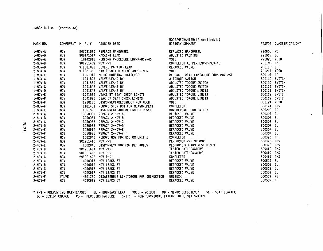
Table B.1.c. (continued)
MODE/MECHANISM(if applicable)HISTORY SUMMARYMARK NO. COMPONENT M. R. # PROBLEM DESC RTSVDT CLASSIFICATION*
1-MOV-A1-MOV-D1-MOV-A2-MOV-D2-MOV-D2-MOV-D1-MOV-E1-MOV-A1-MOV-B1-MOV-C1-MOV-D1-MOV-E1-MOV-F2-MOV-F2-MOV-F1-MOV-E2-MOV-A2-MOV-B2-MOV-C2-MOV-D2-MOV-E2-MOV-F2-MOV-E2-MOV-E2-MOV-E2-MOV-B2-MOV-C2-MOV-A2-MOV-A2-MOV-B2-MOV-C2-MOV-E2-MOV-F2-MOV-F
NOVMOVNOVMOVMOVNOVMOVMOV
MOVNOVNOVNOV
MOVNOVNOV
MOVNOV
MOVNOV
NOVNOV
VALVENOV
90703153090917151710142910901251409911081020911081355
10619101041823104183010418421041845104182510418261210100118143110618253050930305093130509323050933305093430509351062046
9012514101062045
901251407901251408901251406409091340909144090915409091742912304090918
REPLACE HANDWHEELPACKING LEAKPERFORM PROCEDURE EMP-P-MOV-45MOV PMSSEVERE PACKING LEAKLIMIT SWITCH NEEDS ADJUSTMENTMOTOR HOUSING SHATTEREDVALVE LEAKS BYVALVE LEAKS BYVALVE LEAKS BYVALVE LEAKS BYLEAKS BY SEAT CHECK LIMITSLEAK BY SEAT CHECK LIMITSDISCONNECT+RECONNECT FOR MECHREMOVE STEM NUT FOR MEASUREMENTDISCONNECT AND RECONNECT POWERREPACK 2-MOV-AREPACK 2-MOV-BREPACK 2-MOV-CREPACK 2-MOV-DREPACK 2-MOV-EREPACK 2-MOV-FREMOVE MOV FOR USE ON UNIT 1MOV PMSDISCONNECT MOV FOR MECHANICSNOV PMSMOV PMSMOV PMSMOV LEAKS BYMOV LEAKS BYMOV LEAKS BYMOV LEAKS BYDISASSEMBLE LIMITORQUE FOR INSPECTIONMOV LEAKS BY
REPLACED HANDWHEELADJUSTED PACKINGVOIDCOMPLETED AS PER EMP-P-MOV-45REPACKED VALVEVOIDREPLACED WITH LIMTORQUE FROM MOV 251A TORQUE SWITCHADJUSTED TORQUE SWITCHADJUSTED TORQUE SWITCHADJUSTED TORQUE LIMITSADJUSTED TORQUE LIMITSADJUSTED TORQUE LIMITSVOIDCOMPLETEDMOV REPLACED ON UNIT IREPACKED VALVEREPACKED VALVEREPACKED VALVEREPACKED VALVEREPACKED VALVEREPACKED VALVECOMPLETEDPERFORMED PMS ON MOVRECONNECTED AND TESTED MOVTESTED SATISFACTORYTESTED SATISFACTORYCOMPLETEDREPACKED VALVEREPACKED VALVEREPACKED VALVEREPACKED VALVEUNSTUCKREPACKED VALVE
790808790919791023791106791110791217800107800119800119800119800119800119800119800124800124800219800307800307800307800307800307800307800323800325800325800410800410800411800509800509800509800509800509800509
MDBLVOIDPMSBLVOIDPGSWITCHSWITCHSWITCHSWITCHSWITCHSWITCHVOIDPMSPGBLBLBLBLBLBLPGPMSPMSPMSPMSPMSBLBLBLBLPGBL
w
tU
* PMS - PREVENTIVE MAINTENANCE BL - BOUNDARY LEAK VOID - VOIDED MD - MINOR DEFICIENCY SL - SEAT LEAKAGEDC - DESIGN CHANGE PG - PLUGGING FAILURE SWITCH - NON-FUNCTIONAL FAILURE OF LIMIT SWITCH

Table B.1.c. (continued)
MODE/MECHANISM(if applicable)HISTORY SUMMARYMARK NO. COMPONENT M. R. I PROBLEM DESC RTSVDT CLASSIFICATION*
2-MOV-D2-MOV-A2-MOV-B2-MOV-D2-MOV-F2-MOV-B2-MOV-A2-MOV-D2-MOV-B2-MOV-B2-MOV-B1-MOV-B1-MOV-B1-MOV-B1-MOV-D1-MOV-D1-MOV-F1-MOV-F1-MOV-C1-MOV-E1-MOV-C1-MOV-E1-MOV-F2-MOV-A1-MOV-D1-MOV-A1-MOV-A1-MOV-A1-MOV-E1-MOV-B1-MOV-A1-MOV-D1-MOV-E1-MOV-F
VALVEVALVEVALVEMOVMOVMOVMOVMOVMOVMOVMOVMOVMOVMOVMOVMOVMOVMOVMOVMOVVALVEVALVEMOVVALVEVALVEMOVMOVMOVMOVMOVMOVMOVMOVMOV
4211429428045742804565281601
9012514117160826716113040909168230940
110117308230615
9051808401119110190701209070118
1119110211191103907011690701199070117
10323747103230748906180842104221730104300145
8081510103131730
9070121106100420101201701103110840
9241901109300130110011750
VALVE OPEN WHEN SHOULD BE SHUTHANDWHEEL MISSINGHANDWHEEL MISSINGMOV IS SHUT BREAKER IS OPENMOV PMSPACKING LEAKPACKING LEAKMOV LEAKS BYTORQUE SWITCH PROBLEMMOV WILL NOT OPERATEVALVE WILL NOT OPENLEAKS THROUGHDISCONNECT AND RECONNECT FOR MECHANICSPERFORM PMSPERFORM PMSDISCONNECT AND RECONNECT FOR MECHDISCONNECT AND RECONNECT FOR MECHANICSPERFORM PMSPERFORM PMSPERFORM PMSREPACK VALVEREPACK VALVELEAKS THRUREPACK, ADJUST PACKINGADJUST LIMITSREPAIR LIMIT SWITCHDISCONNECT/RECONNECT FOR MECHANICSPERFORM PMSCHECK CONTROL CIRCUIT FOR POSS GROUNDCONT AND PWR CABLES DETERM FROM OPERVALVE STIFFGROUND AND REPAIR WELDSVALVE HAS BODY BONNET LEAKMOV INDICATE CLOSED LOCALLY
VALVE OPERATES AS DESIGNEDVOIDVOIDADJUSTED SWITCHCOMPLETED AS PER ABOVE PROCEDURESCLEANED VALVE STEMREPAIRED LEAKVOIDREPAIRED BROKEN WIREREPAIRED LEADS, TEST SWITCH SATISFACTORYVOID - MRS2011011730COMPLETEDCOMPLETED AS PER EMP-C-MOV-11PMS COMPLETEDPMS COMPLETEDCOMPLETED AS PER EMP-C-MOV-l1DISCONNECT AND RECONNECTPERFORMED AS PER PMSPERFORMED PMS ON VALVEPERFORMED PMS ON VALVEREPACKED VALVEREPACKED VALVENEEDED TO BE WIRED UPCOMPLETEDCOMPLETED AS PER EMP-C-MOV-63VOID - PERFORMED ON ANOTHER MRADJUSTED LIMITS AS PER PROCEDURECOMPLETED AS PER PMS PROCEDURECOMPLETED AS PER EMP-C-MOV-63VOID - WORK PERFORMED ON ANOTHER MRCOMPLETEDVOID - INSPECTION SHOWS NO WELD REPAIRREPLACED GASKETCOMPLETED - VALVE DOES NOT WORK SAT
800513800521800521800602800604800717800718800724800826801104810107810112810222810222810222810222810308810308810311810311810324810324810325810425810531810601810604810604810611810612810618810624811001811001
PGVOIDVOIDPGPMSBLBLVOIDPGPGVOIDSLPMSPMSPMSPMSPMSPMSPMSPMSBLBLPGBLSWITCHVOIDPMSPMSPGVOIDPGVOIDBLPG
tS)0o
* PMS - PREVENTIVE MAINTENANCE BL - BOUNDARY LEAK VOID - VOIDED MD - MINOR DEFICIENCY SL - SEAT LEAKAGEDC - DESIGN CHANGE PG - PLUGGING FAILURE SWITCH - NON-FUNCTIONAL FAILURE OF LIMIT SWITCH

Table B.l.c. (continued)
MODE/MECHANISM(if applicable)HISTORY SUMMARYMARK NO. COMPONENT M. R. # PROBLEM DESC RTSVDT CLASSIFICATION*
1-MOV-A1-MOV-E1-MOV-F2-MOV-C2-MOV-C1-MOV-F1-MOV-F1-MOV-C2-MOV-C2-MOV-F2-MOV-E1-MOV-F2-MOV-F2-MOV-F2-MOV-D1-MOV-F1-MOV-F1-MOV-F1-MOV-F1-MOV-F1-MOV-C1-MOV-E1-MOV-E1-MOV-F1-MOV-F2-MOV-A2-MOV-A2-MOV-B2-MOV-B2-MOV-B1-MOV-F2-MOV-BDF2-MOV-A2-MOV-A
MOVMOVVALVEVALVEMOVVALVEMOVINSTRMOVVALVEMOVMOVVALVEVALVEVALVESWITCHMOVMOVVALVEMOVVALVEVALVEVALVEVALVEMOVVALVEVALVEVALVEVALVEVALVEMOVCONTROLMOVMOV
905180841905180843112050738111121519112211400201140700201072020203201713204090840204121330204092327205120140205201502206090901204090700203120415208140700208120135208141901210130602210130858210151232210141540210151234210140101204150708203010317204150711212101721212101720209081016212172011212151515212161045
LEAKS THROUGHLEAKS THROUGHVALVE INDICATES INTERMITTENT POSITIONREPAIR GEAR BOXINTERMEDIATE INDICATION1-MOV-F FAILS TO INDICATE FULLYINTERMEDIATE INDICATION ON VALVEVALVE SHOWS INTERMEDIATE INDICATIONINTERMEDIATE LIGHTBODY TO BONNET LEAKBODY TO BONNETVALVE WOULD NOT CLOSE FULLYDISCONNECT/RECONNECT FOR MECH DEPTFURMANITE BODY TO BONNET LEAKVALVE DOES NOT CLOSEVALVE CYCLES NORMALLY, HOWEVER, LIGHTCHANGE LIMITORQUEVALVE WILL NOT OPERATE BREAKER THERMVALVE MOVES SLOW PER PT 18.6, INSPECTVALVE WILL NOT FULLY CLOSEPACKING LEAKVALVE HAS SLIGHT PACKING LEAKADJUST LIMIT SWITCHVALVE HAS PACKING LEAKMOV WILL NOT CLOSEDISCONNECT/RECONNECT FOR MECHANICSVALVES LEAK BY WHEN SHUTDISCONNECT/RECONNECT FOR MECHANICSDISCONNECT/RECONNECT FOR NECHANICSOVERHAULDISASSEMBLE LIHITORQUEWHEN LO-LO S/G LEVEL WAS RECEIVEDBODY TO BONNET LEAKDISCONNECT/RECONNECT FOR MECHANICS
VOIDVOIDLIMITS ADJUSTED, SATISFACTORYRENEWED BEVEL GEARVALVE OPERATES SATISFACTORYADJUSTED VALVE, SATISFACTORYVOIDADJUSTED LIMITS. CYCLED SATISFACTORYREPLACED LIMIT SWITCH, TESTED SATTIGHTENED BONNET NUTS ON VALVEVOIDVOIDRECONNECTED, TESTED SATVOIDVOID - NO WORK PERFORMED, OPER DIDN'T HOWORK PERFORMED ON MRS 1208120135INSTALLED NEW LIMITORQUEDISCONNECTED/RECONNECTED SATISFACTORYVOID - COMPLETED ON MR 0208140700DISCONNECTED/RECONNECTED MOV. SATREPACKED VALVEADJUSTED PACKINGCYCLED SATISFACTORYADJUSTED PACKINGREMACHINED SEAT RINGDISCONNECT/RECONNECT. TESTED SATINSPECTED, FOUND NOTHING WRONGRECONNECTED, TESTED SATISFACTORYVOID - DUPLICATE WKPERF ON MR 0204150711MANUFACTURED AND INSTALLEDVOID - NOT ENOUGH LEFT TO REBUILDREWIRED BREAKERS ASREPLACED BONNET GASKETRECONNECTED, TESTED SATISFACTORY
811024811024811206811207811223820114820115820407820409820412820415820517820522820615820809820814820814820814820827821014821015821018821018821018821018821211821212821214821214821216821218821218821221821221
* VOIDVOIDSWITCHPGSWITCHSWITCHVOIDSWITCHSWITCHBLVOIDVOIDPMSVOIDVOIDVOIDPGPGVOIDPGBLBLSWITCHBLPGPMSPMSPMSVOIDSLVOIDPGBLPMS
.w-j
* PMS - PREVENTIVE MAINTENANCE BL - BOUNDARY LEAK VOID - VOIDED MD - MINOR DEFICIENCY SL - SEAT LEAKAGEDC - DESIGN CHANGE PG - PLUGGING FAILURE SWITCH - NON-FUNCTIONAL FAILURE OF LIMIT SWITCH

Table B.1.c. (continued)
MODE/MECHANISM(if applicable)HISTORY SUMMARYMARK NO. COMPONENT M. R. I PROBLEM DESC RTSVDT CLASSIFICATION*
1-MOV-E1-MOV-C1-MOV-E1-MOV-A1-MOV-F1-MOV-B1-MOV-D1-MOV-F1-MOV-B1-MOV-C1-MOV-D1-MOV-B1-MOV-D1-MOV-E1-MOV-F1-MOV-C2-MOV-F1-MOV-E1-MOV-F2-MOV-C1-MOV-B1-MOV-C1-MOV-E1-MOV-B1-MOV-D1-MOV-F1-MOV-D2-MOV-A2-MOV-C2-MOV-C2-MOV-F2-MOV-E2-MOV-C1-MOV-F
MOVVALVEVALVEVALVEVALVEVALVEVALVEVALVEMOVMOVMOVMOVVALVEVALVEVALVEMOVVALVELIMITORQMOVVALVEMOVNOVMOVMOVMOVMOVMOVCOUPLINGVALVEMOVMOVMOVMOVVALVE
303100215302131114302131004302131117302131001302131115302131111302131109303162000303162001303162002304071316304072030304072057304072101304230521304240145304130900304130905304230659304260408304260411304260421305061620305061618305061617305111830306061519305131902304231524307050610308120142306121830210130601
AGASTAT CONTACT IS STICKINGVALVE LEAK BYPACKING LEAKVALVE LEAKS BYPACKING LEAKVALVE LEAKS BYVALVE LEAKS BYVALVE LEAKS BYDISC/RECON FOR MECHSDISC/RECON FOR MECHSDISC/RECON FOR MECHSPACKING LEAKVALVE OPENS BUT WILL NOT CLOSEVALVE LEAKSVALVE LEAKS BY SEATVALVE MOTOR IS LOOSEVLV WHEN CLOSED CAME BACK OPENVALVE LEAKS THRUVALVE LEAKS THRUDRIVE MECHANISM BROKENOPENING TIME IS GREATER THAN 25 PERCOPENING TIME IS GREATER THAN 25 PERCOPENING TIME IS GREATER THAN 25 PERCREPLACE OVERLOAD ASSEMBLYREPLACE OVERLOADREPLACE OVERLOADVALVE CLOSESFLEXIBLE COUPLING LEAKSMOV EXCEEDS INVESTIGATE CAUSEINSTALL LOCAL INDICATING ROD ON MOVMOV WONT STAY CLOSED2-MOV-E HAS BODY TO BONNET LEAKSTRK TIME GREATER THAN 25 PERCVALVE WILL NOT GO FULLY CLOSED
ADJUSTED MICROSWITCHCOMPLETEDCOMPLETEDOVERHAULED VALVEVOID COMP UNDER MR 302131109OVHL VALVE + REPLACEDOVHL VALVE + REPACKEDOVHL VALVEVOID DISC/REC PERF BY DANIELSVALVE RECONNECTEDVOID DISC/REC PERF BY DANIELSADJUSTED PACKINGADJUSTED LIMITSINVESTIGATE LEAKINVESTIGATE LEAKDISCONNECTED ANDVALVE CYCLED SATVALVE CYCLED SATVALVE CYCLED SATREPLACED DESTROYED MOV WITH NEW MOVPT 18.6 UPDATEDPT 18.6 UPDATEDPT 18.6 UPDATEDREPLACED OVERLOADSREPLACED OVERLOADSREPLACED OVERLOADSCYCLED VALVEREPLACED LEAKING TUBEVOID DUPLICATE MRFABRICATED + INSTALLED INDICATORCYCLED SATTIGHTENED ALL NUTSENGINEERING TO EVALUATE STROKEVOID
830313830314830314830315830318830321830321830321830406830406830406830411830411830417830417830423830424830426830426830426830505830505830505830511830511830511830520830608830616830810830819830822830913831019
PGSLBLSLVOIDSLSLSLVOIDPMSVOIDBLPGSLSLPGPGPMSPMSPGMDMDMDDCDCDCPGMDVOIDPMSPGBLMDVOID
wIo
* PMS - PREVENTIVE MAINTENANCE BL - BOUNDARY LEAK VOID - VOIDED MD - MINOR DEFICIENCY SL - SEAT LEAKAGEDC - DESIGN CHANGE PG - PLUGGING FAILURE SWITCH - NON-FUNCTIONAL FAILURE OF LIMIT SWITCH

Table B.1.c. (continued)
MODE/MECHANISM(if applicable)HISTORY SUMMARYMARK NO. COMPONENT M. R. # PROBLEM DESC RTSVDT CLASSIFICATION*
2-MOV-A2-MOV-C2-MOV-E1-MOV-B1-MOV-C1-MOV-D2-MOV-B2-MOV-f2-MOV-F1-MOV-C1-MOV-E2-MOV-A2-MOV-A2-MOV-A2-MOV-B2-MOV-B2-MOV-B2-MOV-B2-MOV-C2-MOV-C2-MOV-D2-MOV-D2-MOV-f2-MOV-E2-MOV-E2-MOV-E2-MOV-F2-MOV-F1-MOV-E2-MOV-F1-MOV-F1-MOV-F1-MOV-F1-MOV-B
MOVMOVMOVMOVMOVMOVVALVEVALVEVALVEVALVEVALVEVALVEVALVEMOVAGASTATVALVEVALVEVALVEVALVEVALVEVALVEVALVEVALVEAGASTATVALVEVALVEVALVEVALVEVALVEVALVEVALVEVALVEVALVEVALVE
312120912312120910312120911401271144410271145402251534403140646403131424403140648403290922403290924403140728403140645403311426404010900403140729403310711403310712403131423308061207403310710403300845308061209404011400403140647403140730403140731403300847403290930401131605403290931404142132404142131403290927
WRONG PLUG IN BOTTOM OF MOVWRONG PLUG IN BOTTOM OF MOVWRONG PLUG IN BOTTOM OF MOVLIFT LEAD AS REQUESTED BY OPSLIFT LEAD AS REQUESTED BY OPERATORSLIMIT SWITCH DOES NOT MAKEUPDISCONNECT AND RECONNECT VALVEELECTRICAL DISCONNECT/RECONNECT VALVEDISCONNECT AND RECONNECT VALVEOPEN, INSPECT, REPAIROPEN, INSPECT, AND REPAIRSUSPECT VALVE LEAKING AT SEATDISCONNECT AND RECONNECT VALVEBODY TO BONNET LEAKCLEAN AGASTATSUSPECT VALVE LEAKING BY SEATOPEN, INSPECT, REPAIRDISCONNECT/RECONNECT FOR MAINTENANCEELECTRICAL DISCONNECT/RECONNECT VALVEREPAIR VALVEOPEN, INSPECT, AND REPAIR.DISCONNECT AND RECONNECT VALVEREPAIR VALVECLEAN AGASTATDISCONNECT AND RECONNECT VALVESUSPECT VALVE LEAKING BY SEATSUSPECT VALVE LEAKING BY SEATDISCONNECT AND RECONNECT MOVELECTRICAL DISCONNECT AND RECONNECTVALVE OPENSELECTRICAL DISCONNECT AND RECONNECTREPAIR PACKING LEAKREPAIR BODY TO BONNET LEAKELECTRICAL DISCONNECT AND RECONNECT
CORRECT PLUG INSTALLEDCORRECT PLUG INSTALLEDCORRECT PLUG INSTALLEDVOIDVOIDCYCLED VALVEADJUSTED LIMITS, RECONNECTED LOAD,RECONNECTED LOAD CHECK BRIDGE & MEGGERRECONNECTED LOAD, CHECKED BRIDGE & MEGVOID - VERIFIED NO LEAK BYVOID - VERIFIED NO LEAK BYDISASSEMBLED VALVE CRACKEDDISCONNECTED AND RECONNECTED ASTORQUED BOLTSCLEANED AGASTAT AND OPERATEDDISASSEMBLED VALVE CRACKEDDISSAMBLED VALVE TACK WELDED PLUGDISCONNECTED AND RECONNECTED MOTORDISCONNECTED AND RECONNECTED ASDISASSEMBLED VALVE CRACKEDCLEANED FOR TACKING TACH WELD PLUGDISCONNECTED/RECONNECTED MOTORDISASSEMBLED VALVE CRACKEDCLEANED AGASTAT AND OPERATED SATDISCONNECTED AND RECONNECTED ANDDISASSEMBLED VALVE CRACKEDDISASSEMBLED VALVE CRACKEDDISCONNECTED AND RECONNECTEDVOID - NOT TO BE WORKEDAGASTAT STICKINGDISCONNECTED AND RECONNECTEDVOID - COMPLETED ON MR 1404142131TORQUED BODY TO BONNETVOID - NO WORK NEEDS TO BE PERFORMED
840107840107840107840130840130840309840326840330840330840404840404840406840406840406840406840406840406840406840406840406840406840406840406840406840406840406840406840406840410840412840417840417840417840419
MDMDMDVOIDVOIDSWITCHPMSPMSPMSVOIDVOIDSLPMSBLPMSSLMDPMSPMSSLMDPMSSLPMSPMSSLSLPMSVOIDPGPMSVOIDBLVOID
wk"I%O
* PMS - PREVENTIVE MAINTENANCE BL - BOUNDARY LEAK VOID - VOIDED MD - MINOR DEFICIENCY SL - SEAT LEAKAGEDC - DESIGN CHANGE PG - PLUGGING FAILURE SWITCH - NON-FUNCTIONAL FAILURE OF LIMIT SWITCH
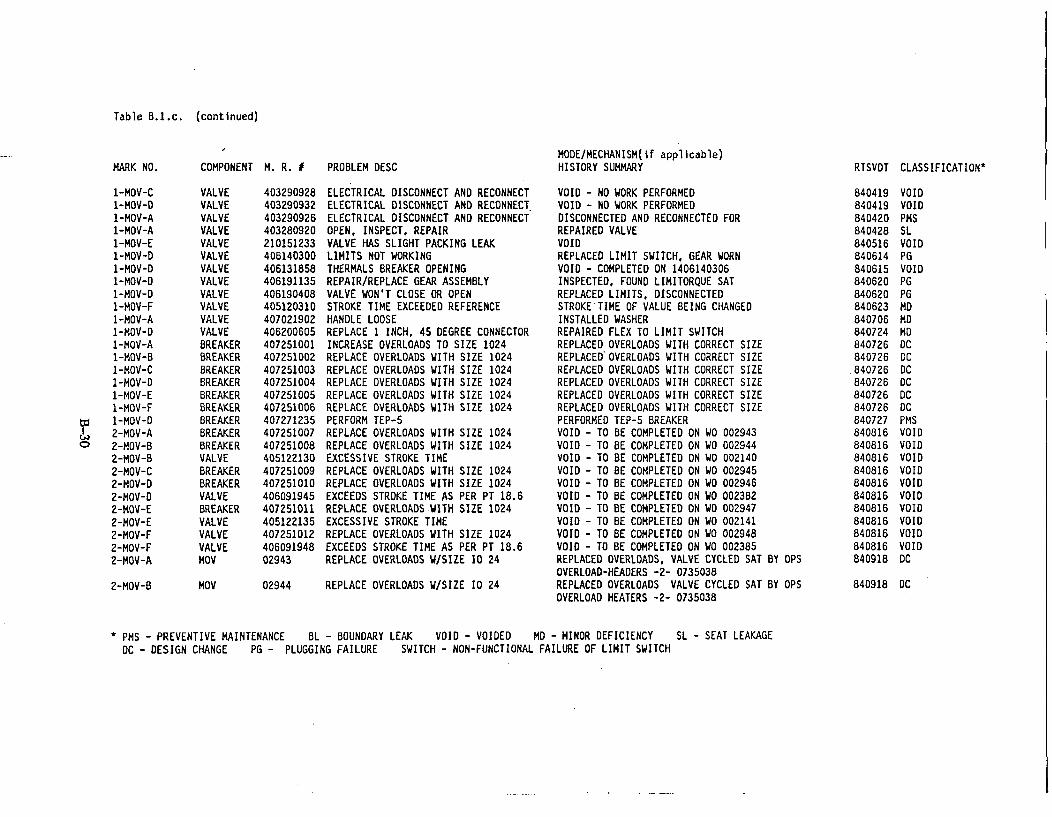
Table B.I.c. (continued)
MODE/MECHANISM(if applicable)HISTORY SUMMARYMARK NO. COMPONENT M. R. I PROBLEM DESC RTSVDT CLASSIFICATION*
1-MOV-C1-MOV-D1-MOV-A1-MOV-AI-MOV-E1-MOV-D1-MOV-D1-MOV-D1-MOV-D1-MOV-F1-MOV-A1-MOV-D1-MOV-A1-MOV-B1-MOV-C1-MOV-D1-MOV-E1-MOV-F1-MOV-D2-MOV-A2-MOV-B2-MOV-B2-MOV-C2-MOV-D2-MOV-D2-MOV-E2-MOV-E2-MOV-F2-MOV-F2-MOV-A
VALVEVALVEVALVEVALVEVALVEVALVEVALVEVALVEVALVEVALVEVALVEVALVEBREAKERBREAKERBREAKERBREAKERBREAKERBREAKERBREAKERBREAKERBREAKERVALVEBREAKERBREAKERVALVEBREAKERVALVEVALVEVALVEMOV
MOV
403290928 ELECTRICAL DISCONNECT AND RECONNECT403290932 ELECTRICAL DISCONNECT AND RECONNECT.403290926 ELECTRICAL DISCONNECT AND RECONNECT403280920 OPEN, INSPECT, REPAIR210151233 VALVE HAS SLIGHT PACKING LEAK406140300 LIMITS NOT WORKING406131858 THERMALS BREAKER OPENING406191135 REPAIR/REPLACE GEAR ASSEMBLY406190408 VALVE WON'T CLOSE OR OPEN405120310 STROKE TIME EXCEEDED REFERENCE407021902 HANDLE LOOSE406200605 REPLACE 1 INCH, 45 DEGREE CONNECTOR407251001 INCREASE OVERLOADS TO SIZE 1024407251002 REPLACE OVERLOADS WITH SIZE 1024407251003 REPLACE OVERLOADS WITH SIZE 1024407251004 REPLACE OVERLOADS WITH SIZE 1024407251005 REPLACE OVERLOADS WITH SIZE 1024407251006 REPLACE OVERLOADS WITH SIZE 1024407271235 PERFORM TEP-5407251007 REPLACE OVERLOADS WITH SIZE 1024407251008 REPLACE OVERLOADS WITH SIZE 1024405122130 EXCESSIVE STROKE TIME407251009 REPLACE OVERLOADS WITH SIZE 1024407251010 REPLACE OVERLOADS WITH SIZE 1024406091945 EXCEEDS STROKE TIME AS PER PT 18.6407251011 REPLACE OVERLOADS WITH SIZE 1024405122135 EXCESSIVE STROKE TIME407251012 REPLACE OVERLOADS WITH SIZE 1024406091948 EXCEEDS STROKE TIME AS PER PT 18.602943 REPLACE OVERLOADS W/SIZE 10 24
02944 REPLACE OVERLOADS W/SIZE 10 24
VOID - NO WORK PERFORMEDVOID - NO WORK PERFORMEDDISCONNECTED AND RECONNECTED FORREPAIRED VALVEVOIDREPLACED LIMIT SWITCH, GEAR WORNVOID - COMPLETED ON 1406140306INSPECTED, FOUND LIMITORQUE SATREPLACED LIMITS, DISCONNECTEDSTROKE TIME OF VALUE BEING CHANGEDINSTALLED WASHERREPAIRED FLEX TO LIMIT SWITCHREPLACED OVERLOADS WITH CORRECT SIZEREPLACED OVERLOADS WITH CORRECT SIZEREPLACED OVERLOADS WITH CORRECT SIZEREPLACED OVERLOADS WITH CORRECT SIZEREPLACED OVERLOADS WITH CORRECT SIZEREPLACED OVERLOADS WITH CORRECT SIZEPERFORMED TEP-5 BREAKERVOID - TO BE COMPLETED ON WO 002943VOID - TO BE COMPLETED ON WO 002944VOID - TO BE COMPLETED ON WO 002140VOID - TO BE COMPLETED ON WO 002945VOID - TO BE COMPLETED ON WO 002946VOID - TO BE COMPLETED ON WO 002382VOID - TO BE COMPLETED ON WO 002947VOID - TO BE COMPLETED ON WO 002141VOID - TO BE COMPLETED ON WO 002948VOID - TO BE COMPLETED ON WO 002385REPLACED OVERLOADS. VALVE CYCLED SAT BY OPSOVERLOAD-HEADERS -2- 0735038REPLACED OVERLOADS VALVE CYCLED SAT BY OPSOVERLOAD HEATERS -2- 0735038
840419840419840420840428840516840614840615840620840620840623840706840724840726840726840726840726840726840726840727840816840816840816840816840816840816840816840816840816840816840918
VOIDVOIDPMSSLVOIDPGVOIDPGPGMDMDMDDCDCDCDCDCDCPMSVOIDVOIDVOIDVOIDVOIDVOIDVOIDVOIDVOIDVOIDDC
0
2-MOV-B 840918 DC
* PMS - PREVENTIVE MAINTENANCE BL - BOUNDARY LEAK VOID - VOIDED MD - MINOR DEFICIENCY SL - SEAT LEAKAGEDC - DESIGN CHANGE PG - PLUGGING FAILURE SWITCH - NON-FUNCTIONAL FAILURE OF LIMIT SWITCH

Table B.1.c. (continued)
MARK NO.
2-MOV-C
2-MOV-D
2-MOV-E
2-MOV-F
1-MOV-B
1-MOV-B
1-MOV-D
COMPONENT
MOV
MOV
MOV
MOV
MOV
M. R. #
02945
02946
02947
02948
1876
PROBLEM DESC
REPLACE OVERLOADS W/SIZE 10 24
REPLACE OVERLOADS W/SIZE 10 24
REPLACE OVERLOADS W/SIZE 10 24
REPLACE OVERLOADS V/SIZE 10 24
INSPECT VALVE
1-MOV-D
1-MOV-Dw
1-MOV-F
1-MOV-F
1-MOV-F
1-MOV-A1-MOV-B1-MOV-Df1-MOV-F
MOV 4484 DISCONNECT/RECONNECT MOV FORMECH
MOV 9491 REPAIR LINEAR INDICATION
MOV 1877 INSPECT VALVE
MOV 4483 DISCONNECT/RECONNECT1-MOV-D
MOV 1878 INSPECT VALVE
MOV 4485 DISCONNECT/RECONNECT1-MOV-F
MOV 10301 PACKING LEAK 1-MOV-F
MOV 7118 1-MOV-A PMSMOV 7119 1-MOV-8 PMSMOV 7121 1-MOV-D PMSMOV 7123 1-MOV-F PMS
MODE/MECHANISM(if applicable)HISTORY SUMMARY
INSTALL OVERLOADS. VALVE CYCLED SAT BY OPSOVERLOAD HEATERS -2- 0735038REPLACED OVERLOADS. VALVE CYCLED SAT BY OPSOVERLOAD HEATERS -2- 0735038REPLACED OVERLOADS. VALVE CYCLED SAT BY OPSOVERLOAD HEATERS -2- 0735038REPLACED OVERLOADS. VALVE CYCLED SAT BY OPSOVERLOAD HEATERS -2- 0735038OPENED VALVE, INSPECTED INTERNALS, CLEANED PLUGAND SEAT, BLUED TO 100% CONTACT. REINSTALLED BODYTO BONNET.DISCONNECTED MOV 10/24/84. VALVE RECONNECTED10/26/84, BUT HAVE NOT CYCLED. CYCLEDMOV-MOV4B ,. OK.GROUND INDICATION OUT OF BODY OF VALVE. MINIMUMWALL THICKNESS WAS NOT VIOLATED BY GRINDING. NDEPART AND REPORT SATISFACTORY.DISASSEMBLED VALVE, AND INSPECTED INTERNALS LAPSEAT AND PLUG AS NECESSARY.MOV DISCONNECTED, COVER HAS 3 BOLTS MISSING(10/24/84). RECONNECTED MOV-CH 11/24/84. CYCLEDMOV-MOV-D , SATISFACTORY.DISASSEMBLED BODY TO BONNET. INSPECTED INTERNALS,CLEANED PLUG AND SEAT, BLUED TO 100%, CONTACTMOV DISCONNECTED 10/24/84. VALVE RECONNECTED10/26/84, BUT HAVE NOT CYCLED. CYCLED MOV-MOV-FOK.EVENED OUT AND ADJUSTED PACKING GLAND, 4 FLATS ONGLAND NUTS. CYCLED VALVE TO ENSURE FREE MOVEMENT.CYCLE VALVE. CHECK LIGHTS INDICATION, AND AMPS.PERFORMED PMS SATISFACTORY (11/30/84).PERFORMED PMS ON MOV-MOV-f (11/30/84).REMOVED MEGGERED MOTOR AND-TOOK LOAD CHECK WHENCYCLING VALVE, 11/30/84.
841203 PMS
841203 MD
841203
841203
841203
841203
841207
841213841213841213841213
PMS
PMS
PMS
PMS
BL
PMSPMSPMSPMS
840918
840918
840918
840918
841203
DC
DC
DC
DC
PMS
RTSVDT CLASSIFICATION*
* PMS - PREVENTIVE-MAINTENANCE BL - BOUNDARY LEAK VOID - VOIDED MD - MINOR DEFICIENCY SL - SEAT LEAKAGEDC - DESIGN CHANGE PG - PLUGGING FAILURE SWITCH - NON-FUNCTIONAL FAILURE OF LIMIT SWITCH

Table B.I.c. (continued)
MODE/NECHANISM(if applicable)HISTORY SUMMARYMARK NO.
1-MOV-C1-MOV-E2-MOV-F1-MOV-F2-MOV-F.2-MOV-B2-MOV-A2-MOV-E
2-MOV-D2-MOV-F
2-MOV-B
2-MOV-D
COMPONENT M. R. I PROBLEM DESC
NOV 7120 1-MOV-C PMSNOV 7122 1-MOV-E PMSMOV 20986 REPAIR VLV 2-MOV-FNOV 13893 1-MOV-F BREAKER TRIPPEDMOV 31197 2-MOV-F INSTALL T DRAINMOV 11243 2-MOV-B AGASTAT TIMERMOV 11246 2-MOV-A AGASTAT TIMERMOV 11244 2-MOV-E AGASTAT TIMER
MOV 11245 2-MOV-D AGASTAT TIMERMOV 13826 2-MOV-F REPLACE AGASTAT
MOV 18180 2-MOV-B DISCONN/RECONN
MOV 18179 2-MOV-D DISCONN/RECONN
MOV 18178 2-MOV-F DISCONN/RECONN
RTSVDT CLASSIFICATION*
PERFORMED PMS SATISFACTORY (11/30/84).PERFORMED PMS, SATISFACTORY 11/30/84.VOID SELECTED AS REPETITIVE MAINT RMN02430BRIDGED AND MEGGERED SATISFACTORY, CYCLED SEVERALINSTALLED -T- DRAIN PLUG IN 2-NOV-FREPLACED AGASTAT TIMER, TESTED SAT.REPLACED AGASTAT TIMER CONNECTED L1-62 COIL LEADSREPLACED AGASTAT TIMER. LI-L2 COIL LEADS ONECONNECTED. COMPLETED WD AGASTAT OK 5/31/85REPLACED AGASTAT. TESTED SAT.REPLACED AGASTAT 4485 CYCLED SAT 6/1/85AGASTAT 4605291DISCONNECTED MOV AS PER EMP-C-HOV-11. RECONNECTEDMOTOR AND LIMITS ADJUSTED AS PER PROCEDUREEMP-C-MOV-11 UNABLE TO CHECK ROTATION OF MOTORTASS MISSING 5/23/85DISCONNECTED MOV AS PER EMP-C-MOV-11 4/8/85.RECONNECTED. COMPLETED STEPS 3.1-523 REQUIRE ELECRUN AND LOAD CHECK. COMPLETED SATDISCONNECTED MOV AS PER EMP-C-MOV-1 1 RECONNECTEDNOV CABLE MARKINGS POOR. VALVE CYCLED SATGASKET COVER 4606098VOID NOT LEAKING 6/12/85REPLACED AGASTAT TIMER CONNECTED 61-62 COIL LEADS5/25/85 COMPLETED. MR AGASTAT 8cVOID NOT LEAKING 6/17/85INSPECT FOR MISSING ZERK FITTINGS NONE MISSINGINSTALLED SWITCH COVER SCREWVOID NOT LEAKINGINSPECT FOR MISSING ZERK FITTINGS. NONE MISSINGINSPECT FOR MISSING ZERK FITTINGS. NONE MISSINGINSPECT FOR MISSING ZERK FITTING. NONE MISSINGINSPECT EDR MISSING ZERK FITTING. NONE MISSINGINSPECT FOR MISSING ZERK FITTING. NONE MISSING
841214841214850204850213850228850523850531850531
850523850601
850605
PMSPMSVOIDPGDCDCDCDC
DCDC
PMS
850605 DC
850605 PMScoWIt')
2-MOV-F
2-MOV-E2-MOV-C
2-MOV-A2-MOV-A2-MOV-B2-MOV-F2-MOV-B2-MOV-C2-MOV-D2-MOV-E2-MOV-F
MOVMOV
MOVMOVMOVMOVMOVMOVMOVMOVMOV
2033113787
203262083020436203272083120832208332083420835
VALVE LEAKS THRU2-MOV-B REPLACE AGASTAT
VALVE LEAKS THRUINSPECT AS REQUIRED2-MOV-B SWITCH COVERVALVE LEAKS THRUINSPECTINSPECTINSPECTINSPECTINSPECT
850612850613
850617850617850617850617850618850618850618850618850618
VOIDDC
VOIDPMSMDVOIDPMSPMSPMSPMSPMS
* PNS - PREVENTIVE MAINTENANCE BL - BOUNDARY LEAK VOID - VOIDED MD - MINOR DEFICIENCY SL - SEAT LEAKAGEDC - DESIGN CHANGE PG - PLUGGING FAILURE SWITCH - NON-FUNCTIONAL FAILURE OF LIMIT SWITCH

Table B.l.c. (continued)
MODE/MECHANISM(if applicable)HISTORY SUMMARYMARK NO.
2-MOV-B2-MOV-C2-MOV-D
2-MOV-E2-MOV-E2-MOV-F
2-MOV-E2-MOV-F
2-MOV-A
2-MOV-E2-MOV-A1-MOV-A1-MOV-B
W I-MOV-C1 1-MOV-D1-MOV-E1-MOV-F1-MOV-D
2-MOV-B
2-MOV-A2-MOV-A2-MOV-B2-MOV-C2-MOV-E
C OM PO0NENMT
NOVMOVNOV
NOVNOVMOY
MOV
MOV
MOV
MOVNOV
MOV
MOVNOVNOVMOV
M. R. f
021402036002382
021412035902333
2098420935
20983
181771364622752276227722782279228022962
42036
2054025950259492594825946
PROBLEM DESC RTSVDT CLASSIFICATION*
EXCESSIVE STROKE TIMEINSTALL GREASE FITTINGINVESTIGATE STROKE TIME
OVERHAUL VALVEINSTALL GREASE FITTINGINVESTIGATE STROKE TIME
2-MOV-E ASSIST MECH2-MOV-F ASSIST MECHS
2-MOV-A ASSIST MECH
2-MOV-E DISCON/RECONNSTROKE TIME EXCEEDS AVG PT18.6REPLACE AGASTATREPLACE AGASTATREPLACE AGASTATREPLACE AGASTATREPLACE AGASTATREPLACE AGASTAT1-MOV-D INVESTIGATE TRIP
2-MOV-B PERFORM EWR WORK
2-MOV-A WONT XFER CONTR2-MOV-A INSTALL T-DRAIN2-MOV-B INSTALL T-DRAIN2-MOV-B INSTALL T-DRAIN2-MOV-E INSTALL T-DRAIN
DISASSEMBLE VALVE AND INSPECT PARTSINSTALL GREASE FITTING #2295726DISASSEMBLED VALVE CLEAN AND INSPECTED INTERNALSREASSEMBLED VALVE WITH NEW BONNET GASKET. STEM,PLUG AND ROTATE REPACKED VALVEREPACKED VALVE WITH GARLOCK 98INSTALL GREASE FITTING #2295726DISASSEMBLED VALVE REPLACED STEM, DISC TORQUE KEY,GASKET DISC WASHER-100 PERCENT BLUE CHECKREASSEMBLED VALVEADJUSTED TORQUE SWITCH SETTING TO 2VALVE CYCLED SAT AS PER OPERATIONS/ NO ADJUSTMENTSNECESSARYVALVE CYCLED SAT AS PER OPERATIONS/ NOADJUSTMENTS WERE NECESSARYVOID COMPLETED ON WO 020984VOID VALVE CYCLED SAT 6/20/85 NO WORK PERFORMEDVOID TO MR 1405251145.VOID TO 1405251146.VOID TO MR 1405251147.VOID TO MR 1405251148.VOID TO MR 1405251149.VOID TO MR 1405251150.WORKED WITH OPERATORS AND CYCLED VALVE;SATISFACTORYNO PROBLEMS FOUND (OPEN 2.5 AMPS,CLOSED 2.5 AMPS).INSTALLED NEW HEATERS AND CHANGED FIELD LEADS ASPER PROCEDURE 10/10/86. SET UP THRUST VALVES ASPER EWRREPLACED COIL ON LATCHING RELAY OLD COIL BURNT UPREPLACED OLD PLUGS WITH 2 BREATHER PLUGS IN MTR.REPLACED OLD PLUGS WITH 2 BREATHER PLUGS IN MTRREPLACE OLD PLUGS WITH 2 BREATHER LUGS IN MTR.REPLACED OLD PLUGS WITH 2 BREATHER LUGS IN MTR.
850620850620850620
850620850620850620
850624850624
850626
850627850628850711850711850711850711850711850711850814
851012
851029851101851101851101851101
PGDCPG
PMSDCPG
PMSPMS
PMS
VOIDPMSVOIDVOIDVOIDVOIDVOIDVOIDPG
DC
PGDCDCDCDC
* PMS - PREVENTIVE MAINTENANCE BL - BOUNDARY LEAK VOID - VOIDED MD - MINOR DEFICIENCY SL - SEAT LEAKAGEDC - DESIGN CHANGE PG - PLUGGING FAILURE SWITCH - NON-FUNCTIONAL FAILURE OF LIMIT SWITCH

Table B.1.c. (continued)
MARK NO.
2-MOV-D2-MOV-F2-MOV-D
2-MOV-E
1-MOV-F1-MOV-D
1-MOV-D
1-MOV-D
1-MOV-D
1-MOV-D
1-MOV-A
COMPONENT
MOVMOVMOV
MOV
MOVMOV
MOV
MOV
MOV
MOV
MOV
M. R. #
259472594538412
38413
296329885
29920
29937
35288
30701
36114
PROBLEM DESC
2-MOV-D INSTALL T-DRAIN2-MOV-F INSTALL T-DRAIN-L-ACTUATOR INSPECTION/REPAIR
-L-ACTUATOR INSPECTION/REPAIR
INVESTIGATE STROKE TIMEINVESTIGATE/REPAIR MOV
E-INVESTIGATE/REPAIR ASREQUIRED
1-MOV-DDISCONNECT/RECONNECT
PACKING ADJUSTMENT
INVESTIGATE/REPAIR LEAK
EWR 85-018C, 85-261A, 85-224B
MODE/MECHANISM(if applicable)HISTORY SUMMARY
REPLACED OLD PLUGS WITH -2- BREATHER PLUGS IN MTRREPLACED OLD PLUGS WITH 2 BREATHER PLUG IN MTRBAD GREASE/WRONG GREASE INSTALLEDREMOVED DISASSEMBLED, CLEANED, REASSEMBLED ANDINSTALLED. CHANGED OUT TRIGGER FINGER.PARTS -7/16- 9/16- 15/16- 1 1/16-BAD GREASE/WRONG KINDRMO, DISASSEMBLED, CLEANED, REPLACEDAND LUBRICATED ACTUATOR, PLACED TRIGGER FINGERSPRING. PARTS- EXXON NEBULA EP-OVOID - NOT REQUIRED AS PER ATTACHED MEMO.RESET THERMO OVERLOADS, TURNED BREAKER ON ANDVALVE AUTOMATICALLY WENT OPEN DRAWING 2.7 AMPS.DREW 2.7 ALL THE WAY CLOSED, THEN DREW 11.3 AMPS.WE THINK THE TORQUE SWITCH IS BROKEN.AS FOUND - DISASSEMBLED LIMITORQUE, FOUND NOINTERNAL DAMAGE OF COMPONENTS. GREASE WAS VERYHARD, CLEANED ALL PARTS AND HOUSINGCHANGED OUTGREASE WITH EP-O, AND REASSEMBLED.DISCONNECTED MOTOR AND LIMIT SWITCH, 1/28/86.REMOVED LIMIT SWITCH AND TORQUE SWITCH. ALSOREMOVED MOTOR FOR MECHANICAL DEPARTMENT,1/29/86. HOOKED UP AND PERFORMED EMP-C-MOV-11SATISFACTORILY.LEAK/PACKINGTIGHTENED PACKING.INVESTIGATION REVEALED THAT GREASE WAS NOTLEAKING, IT WAS JUST RECENTLY CHANGED AND THEGREASE THAT WAS SEEN WAS JUST EXCESS THAT DIDN'TGET WIPED OFF, GREASE WIPED OFF.BRIDGED AND MEGGERED TOO AMP READING. MOTORPULLED HIGHER AMPS THAN NORMAL.
RTSVDT CLASSIFICATION*
851104851104851128
851128
851213860128
860131
860204
860607
860609
860610
DCDCPMS
PMS
VOIDPG
PG
PMS
BL
VOID
PMS
* PMS - PREVENTIVE MAINTENANCE BL - BOUNDARY LEAK VOID - VOIDED MD - MINOR DEFICIENCY SL - SEAT LEAKAGEDC - DESIGN CHANGE PG - PLUGGING FAILURE SWITCH - NON-FUNCTIONAL FAILURE OF LIMIT SWITCH

Table B.I.c. (continued)
MARK NO.
1-MOV-A
1-MOV-D
1-MOV-E
1-MOV-F
COMPONENT
NOV
M. R. # PROBLEM DESC
35258 ACTUATOR INSTALLATION
NOV 35255 ACTUATOR INSPECTION
MOV 35254 ACTUATOR INSPECTION
MOV 36992 1-MOV-F STATIC TEST
MOV 37045 MOV-B EWR 86-224, 85-224C
MOV 36362 MOV-B EWR 85-2248,261A,018C
MOV 37040 NOV-F EWR 86-224, 85-224C
NOV 36367 MOV-D EWR, 85-224B, 261,018C
NOV 37043 NOV-D EWR 86-224. 85-224C
MODE/MECHANISM(if applicable)HISTORY SUMMARY
GREASE/NORMAL WEARDISASSEMBLED, CLEANED, INSPECTED ACTUATOR.REPLACED BAD GASKETS, AND SEAL 0-RINGS.REINSTALLED AND LUBRICATED ACTUATOR. TOOLS 1-1/16COMBINED. 18-BAD LUBRICANT/WRONG LUBRICANTREMOVED ACTUATOR, DISASSEMBLED, CLEANED,INSPECTED, REPLACED GASKETS, AND LUBRICATED ANDREINSTALLED.GREASE/NORMAL WEARDISASSEMBLED. CLEANED, INSPECTED ACTUATOR,REPLACED BAD GASKETS, O-RINGS, QUAD-RINGS, ANDREINSTALLED AND LUBRICATED ACTUATOR.HIGH AMP READING, 6/17/86. ASSISTED MOVATS INTESTING OF VALVE. VALVE OPERATED SATISFACTORY,6/17/86. THRUST SETTINGS 15160, OPENED 15838.COMPLETED EWR 86-224-PI. FINAL THRUST VALVES NO.16160 OPEN, NO. 16020 CLOSE.RESET TORQUE SWITCH 5/31/86. PERFORMED EWR85-224B, 85-01, AND 85-261A.COMPLETED EWR 86-224-Pi. VALVE OPERATEDSATISFACTORY, 6/20/86.MADE ADJUSTMENTS ON TORQUE SWITCH OLD SETTING,2-1/4 OPEN: 2-1/4 CLOSE. CHANGE TO 2-3/8 OPEN;2-3/8 CLOSE. PERFORMED EWR 85-2248.85-068C, ANDCOMPLETED EWR 86-224-PI. COMPLETED EMP-COMOV-151,COMPLETED EMP-C-MOV-18, RETAGGED MOV-MOV-D . TAGREPORT NO. SI-8318BRIDGED AND MEGGERED, AND TOOK LOAD CHECK.COMPLETED EWR-86-224-P1, 6/16/86. ASSISTED MOVATSIN TESTING OF VALVE. COMPLETED EMP-C-MOV-151.VALVE OPERATED SATISFACTORY.
RTSVDT CLASSIFICATION*
860611 PMS
860611 PMS
860611 PMS
860624 PMS
LA
1-MOV-B
1-MOV-B
1-MOV-F
1-MOV-D
860701
860702
860702
860705
PMS
PMS
PMS
PMS
1-MOV-D
1-MOV-EI-MOV-E
860705 PMS
860705 PMS860705 PMS
MOVNOV
36115 EWRS 85-018C. 85-261A, 85-224837042 MOV-E EWR 86-224, 85-224C
* PMS - PREVENTIVE MAINTENANCE BL - BOUNDARY LEAK VOID - VOIDED MD - MINOR DEFICIENCY SL - SEAT LEAKAGEDC - DESIGN CHANGE PG - PLUGGING FAILURE SWITCH - NON-FUNCTIONAL FAILURE OF LIMIT SWITCH
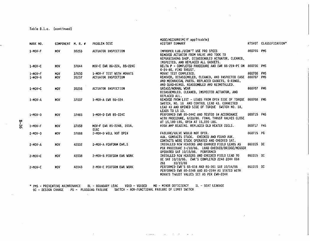
Table B.1.c. (continued)
MARK NO.
1-MOV-F
1-MOV-C
1-MOV-F1-MOV-B
1-MOV-C
1-MOV-A
COMPONENT
MOV
MOV
MOVMOV
MOV
MOV
MOV
MOV
MOV
MOV
MOV
MOV
M. R. f PROBLEM DESC
35253 ACTUATOR INSPECTION
37044 MOV-C EWR 86-224, 85-224C
37650 1-MOV-F TEST WITH MOVATS35257 ACTUATOR INSPECTION
35256 ACTUATOR INSPECTION
37037 1-MOV-A EWR 86-224
37465 1-MOV-D EWR 85-224C
37058 MOV-F EWR 85-224B, 261A,018C
37688 2-MOV-D WILL NOT OPEN
42032 2-MOV-A PERFORM EWR.S
42038 2-MOV-B PERFORM EWR WORK
42043 2-MOV-E PERFORM EWR WORK
MODE/MECHANISM(if applicable)HISTORY SUMMARY
IMPROPER LUB./DIDN'T USE PRO SPECSREMOVED ACTUATOR FROM VALVE AND TOOK TOREFURBISHING SHOP. DISASSEMBLED ACTUATOR, CLEANED,INSPECTED, AND REPLACED ALL GASKETS.DELTA P - COMPLETED PROCEDURE AND EWR 86-224-PI ON6-24-86. FIND THRUST.MOVAT TEST COMPLETED.REMOVED, DISASSEMBLED, CLEANED, AND INSPECTED CASEAND MECHANICAL PARTS. REPLACED GASKETS, O-RINGS,AND QUAD-RINGS. REASSEMBLED AND REINSTALLED.GREASE/NORMAL WEARDISASSEMBLED, CLEANED, INSPECTED ACTUATOR. ANDREPLACED ALL.REMOVED FROM LIST - LEADS FROM OPEN SIDE OF TORQUESWITCH, NO. 18 AND CONTROL LEAD 43. CONNECTEDLEAD 43 AND OPENED SIDE OF TORQUE SWITCH NO. 18,LEADS TO LS 13.PERFORMED EWR 85-244C AND TESTED IN ACCORDANCEWITH PROCEDURE. 6/23/86. FINAL THRUST VALVES CLOSEAT 15,180 LBS, OPEN AT 15,220 LBS.HIGH AMP READING. REPLACED OLD HEATER COILS.
FAILURE/VALVE WOULD NOT OPER.AUX. CONTACTS STUCK. CHECKED AND FOUND AUX.CONTACTS WERE STUCK OPERATED AND CHECKED SAT.INSTALLED NEW HEATERS AND CHANGED FIELD LEADS ASPER PROCEDURE 1-/10/86. LOAD CHECKED/BRIDGE/MEGGEROPERATED SAT 10/15/86. PERFORMEDINSTALLED NEW HEATERS AND CHECKED FIELD LEAD TOBE SAT 10/10/86. EWR'S COMPLETED 2248 224H 018261 10/15/86PERFORMED EWR'S 85-018 AND 85-261 SAT 10/14/86PERFORMED EWR 86-224B AND 85-224H AS STATED WITHMOVATS THRUST VALUES SET AS PER EWR-224H
RTSVDT CLASSIFICATION*
860705 PMS
ot0d
1-MOV-D
1-MOV-F
2-MOV-D
2-MOV-A
2-MOV-C
2-MOV-E
860706
860706860707
860707
860708
860715
860717
860715
861015
861015
861015
PMS
PMSPMS
PMS
PMS
PMS
PMS
PG
DC
DC
DC
* PMS - PREVENTIVE MAINTENANCE BL - BOUNDARY LEAK VOID - VOIDED MD - MINOR DEFICIENCY SL - SEAT LEAKAGEDC - DESIGN CHANGE PG - PLUGGING FAILURE SWITCH - NON-FUNCTIONAL FAILURE OF LIMIT SWITCH

Table B.1.c. (continued)
MARK NO.
2-MOV-D
2-MOV-F
2-MOV-A
2-MOV-B
2-MOV-A
COMPONENT M. R. # PROBLEM DESC
MOV 42040 2-MOV-D PERFORM EWR WORK
MOV 42050 2-MOV-F PERFORM EWR WORK
MOV 38409 ACTUATOR INSPECTION AND REPAIR
MOV 38410 ACTUATOR INSPECTION AND REPAIR
MOV 20987 REPAIR VLV 2-MOV-A
MODE/MECHANISM(if applicable)HISTORY SUMMARY
INSTALLED HEATERS AND CHANGED FIELD LEADS AS PERPROCEDURE 10/10/86 PERFORMED EWR 86-2248 85-224HIAW MOVATS AND EMP-C-MOV- 10/24/86PERFORMED EWR 85-018 + 85-261 + 86-224 AND TESTEDVALVES PER EWR-85-224H AND MOVATS 10/13/86NA/.BAD GREASE/IMPROPER GREASE INSTALLEDREMOVED ACTUATOR, TRASPORTED TO REFURB SHOP.DISASSEMBLED, CLEANED AND INSPECTED, REPLACEDALL SOFTWARE, REPLACEREMOVED ACTUATOR FROM VALVE & TRANSPORTED TOREFERB SHOP DISASSEMBLED CLEANED, INSPECTED,REPLACED ALL SOFTWARE & DEFECTIVE PARTS.REASSEMBLED USING EXXON NEBULA EP-O GREASEDISASSEMBLED VALVE IAW PROCEDURE & TAPED OPENINGIN SYSTEM SHUT & ALL PARTS IN BAS BY VALVE BODY.LAPPED SEAT & PLUG REINSTALLED BONNET WITH NEWGASKET TROQUED TO 150 FT LBS.REMOVED, DISASSEMBLED. CLEANED, INSPECTED,ASSEMBLED, LUBRICATED, & INSTALLED. BAD GREASE/.WRONG GREASE INSTALLED.UNPACKED AND REPACKED VALVE WITH GARLOCK 98.VOID TO 038413ASSISTED OPERATORS IN OPENING VALVE FULLY FROMMCC. VALVE WENT FULL OPEN, FULL CLOSE WITH PROPERINDICATION. WORK PERFORMED ON WO 047506, 1/8/87.BAD GREASE/WRONG GREASE INSTALLEDREMOVED DISASSEMBLED, CLEANED, INSPECTED,ASSEMBLED, LUBRICATED, INSTALLED. TOOLS-9/161/2 7/16 COMBINATION 5/16 3/8 ALLENREPAIRED PRONG ON MOV. NEEDED SMALL ADJUSTMENTCYCLED 5 TIMES. EVERYTHING RAN SAT.
RTSVDT CLASSIFICATION*
861025 DC
861025 DC
861101 PMS
861101 PMS
861119 MD
861119 PMS
-J
2-MOV-F
2-MOV-F2-MOV-E1-MOV-D
MOV 38414 -L-ACTUATOR INSPECTION/REPAIR
REPACK VALVEREPAIR VLV 2-MOV-EINVESTIGATE/REPAIR AS NEEDED
MOVMOVMOV
430662098845967
861119861120861123
PMSVOIDPG
2-MOV-C
2-MOV-B
MOV 38411 -L-ACTUATOR INSPECTION/REPAIR
MOV 45784 2-MOV-8 ADJUST LIMITS
861128 PMS
861204 SWITCH
* PMS - PREVENTIVE MAINTENANCE BL - BOUNDARY LEAK VOID - VOIDED MD - MINOR DEFICIENCY SL - SEAT LEAKAGEDC - DESIGN CHANGE PG - PLUGGING FAILURE SWITCH - NON-FUNCTIONAL FAILURE OF LIMIT SWITCH

Table B.1.c. (continued)
MARK NO.
1-MOV-D
1-MOV-C
1-MOV-D
1-MOV-F
1-MOV-E
tU 2-MOV-C
00
1-MOV-C
1-MO V-D
2-MOV-C
2-MOV-F
COMPONENT
MOV
MOV
MOV
MOV
MOV
M. R. #
47664
PROBLEM DESC
ACTUATOR GREASE REPLACEMENT
47314 P.E-OVERHAUL MOV
46491
49034
1-MOV-D ADJUST INDICATORSWITCH1-MOV-F INSPECT HOOK-UP
49801 INVESTIGATE MALFUNCTION
MODE/MECHANISM(if applicable)HISTORY SUMMARY
REPLACED GREASE/PMREMOVED TOP COVER AND CHECKED GREASE, PULLED SIDEPLUG AND CHECKED SAMPLE OF GREASE. DRAINED OUTGREASE AND FILLED TO LEVEL WITH NEW GREASE.CLEAN SPRING PAK./PMREMOVED MOTOR. REPLACED GREASE, REMOVEDWORM/TORQUE SPRING ASSEMBLY, CLEANED. GREASED, ANDREINSTALLED.VOID - TO BE COMPLETED ON 047506
MOTOR HEATER LEADS ARE NOT TERMINATED. 1/31/87.REMOVED LIMIT COVER. LEADS FOR MOTOR HEATERS ARETOO SHORT TO TERMINATE PROPERLY WITHOUT REMOVINGGEARBOXVALVE WOULEN'T OPEN/AUXILIARY OPENINTERLOCK STUCK ON OPENING CIRCUIT. REPLACEDCONTACTOR 2/18/87, CHECKED SATISFACTORY.TIMES. FLA 2.4 ACTUAL, T1 2.4, T2 2.4, AND T3 2.4OKAY.SPRING PACK DISASSEMBLED 12/30/86. S/N 347490.INSTALLED SPRING PACK ONLY. LEFT WITH MOVAT.WORK WAS PERFORMED BY MOVAT.VALVE WOULDN'T OPEN/INCORRECT WIRINGSTARTED TROUBLE SHOOTING. FOUND ONE AGASTAT WIREIN WRONG PLACE. RETURNED TO PROPER PLACE AS PERVALVE WOULDN'T OPEN/INCORRECT WIRINGFOUND X1 LANDED ON WRONG TERMINAL ON AGASTAT.RELANDED CORRECTLY AS ESK 6BY. FOUND IT ON NO. 1CONTACT.PERFORMED DELTA R. EVERYTHING WORKED FINE 3/6/87VALVE WAS CYCLED SATISFACTORY DURING ACTUAL FLOWCONDITION. THRUST VALVE RECORDED DURING CLOSEVOID TO 040444
RTSVDT
870106
CLASSIFICATION*
PMS
870109
870201
VOID
MD
870108 PMS
MOV 46218 REPAIR VALVE
MOV 49725 1-MOV-C CHECK LOGIC, CKT
MOV 49735 1-MOV-D CHECK LOGIC CKT
MOV 49525 2-MOV-B DELTA-R TESTING
MOV 45553 2-MOV-F HIGH AMP READING
870219 PG
870225 PG
870304 NAF
870304 NAF
870316 PMS
870501 VOID
* PMS - PREVENTIVE MAINTENANCE BL - BOUNDARY LEAK VOID - VOIDED MD - MINOR DEFICIENCY SL - SEAT LEAKAGEDC - DESIGN CHANGE PG - PLUGGING FAILURE SWITCH - NON-FUNCTIONAL FAILURE OF LIMIT SWITCH NAF - NOT AN AGING FAILURE (MAINTENANCE ERROR)

Table B.l.d. MAINTENANCE RECORDS FOR THE AUXILIARY FEEDWATER SYSTEM 6-INCH MOTOR OPERATED VALVES
MODE/MECHANISM(if applicable)HISTORY SUMMARYMARK NO. COMPONENT M. R. I PROBLEM DESC RTSVDT CLASSIFICATION*
2-MOV-I1-MOV-G1-MOV-H2-MOV-J2-MOV-J1-MOV-G1-MOV-H1-MOV-G2-MOV-I2-MOV-I2-MOV-I2-MOV-I2-MOV-J2-MOV-J2-MOV-J1-MOV-G1-MOV-G1-MOV-G1-MOV-G1-MOV-G1-MOV-G1-MOV-G2-MOV-I2-MOV-I2-MOV-J2-MOV-J2-MOV-J2-MOV-I2-MOV-I2-MOV-J2-MOV-I2-MOV-I2-MOV-J
MOVMOVMOVVALVEMOVMOVMOVMOVVALVEMOVMOVMOVMOVVALVEVALVEMOVMOVMOVVALVEMOVMOVVALVEVALVEVALVEVALVEVALVEVALVEVALVEMOVVALVEVALVEMOVMOV
20160580805091028805091029810030726812040631910230641
4262145909111345
73012097231425805092980508558122234
1011312001011312016120630
1121204201121503001070115371122412421122813441121322303041916353042315003041916373042314273082618353090514303083115043042317054080509560335220409
PERFORM EMP-P-MOV-45CLEAN AND INSPECTCLEAN AND INSPECTWILL NOT OPERATETHERMALS OUT WON'T OPENMOV WILL NOT OPENMANUAL ENGAGEMENT HANDLEVALVE BINDINGDISCONNECT FOR MECHANICSVALVE IS BINDING UPREPLACE LIMITORQUEDISCONNECT/RECONNECT FOR MECHSVALVE WILL NOT COME FULL OPENVALVE BINDS UNABLE TO CLOSEDISCONNECT/RECONNECT FOR MECHANICSVALVE WILL NOT OPENVALVE WILL NOT CYCLEVALVE DOES NOT TRAVELVALVE BINDS UPELECTRICAL DISC LIMIT ON 1-MOV-ADISCONNECT/RECONNECT MOVWILL NOT FULLY CLOSEVLV CYCLES HI AMPS ON MTR2-MOV-I WILL NOT OPENVLV CYCLES HI AMPS ON MTR2-MOV-J WILL NOT OPENLIMITORQUE GEARBOX LEAKINGVALVE NOT FULLY CLOSEDREPLACE OR REPAIR FLEXIBLE CONDUITVALVE WILL NOT OPENADJUST PACKING OR REPLACEADJUST PACKING OR REPLACE2-MOV-J TORQUE SWITCH
COMPLETEDVOIDVOIDMEG BRIDGED AND TESTED SATISFACTORYCLEANED, CHECKED MOTOR - TEST SATVOIDVALVE OPERATES OKVOIDCONNECTED - TESTED SATREPAIRED VALVEREPAIRED LIMITORQUE OPERATORCOMPLETED AS PER EMP-C-MOV-11NO PROBLEMS FOUNDCLEANED, STEM THREADSMOV TESTED SATISFACTORYCOMPLETEADJUSTED LIMITS ON MOV-MOV-A , SATVOIDVOID - COMPLETED UNDER MR 112132230RECONNECTED & TESTED SATISFACTORYVOIDVOID - UPDATING MRADJUSTED PACKINGCLEANED TORQUE SWITCHADJUSTED PACKINGADJUSTED TORQUE SWITCHFOUND NO GREASE LEAK ON MOVCLEANED CONTACTS, TESTED SATISFACTORYREPLACE FLEX COMPLETEVOIDADJUSTED GLANDVOID-NO PROBLEM EXITSCHECKED TORQUE SWITCH WITH PROCEDURE EMP-S-MOV-143
770928780718780718781006781204791024800429800522800801800801800807800808800814810120810214810423811212811215820128820205820211820217830423830423830423830423830912830913830913840130840808850301850610
PMSVOIDVOIDFCFCVOIDVOIDVOIDPMSFCFCPMSFCFCPMSFCFCVOIDVOIDPMSVOIDVOIDFCFCFCFCMDSWITCHMDVOIDMDVOIDPMS
wv
* PMS - PREVENTIVE MAINTENANCE BL - BOUNDARY LEAK VOID - VOIDED MD - MINOR DEFICIENCY SL - SEAT LEAKAGEDC - DESIGN CHANGE FC - CROSS-CONNECTING FAILURE SWITCH - NON-FUNCTIONAL FAILURE OF LIMIT SWITCH

Table B.1.d. (continued)
MODE/MECHANISM(if applicable)HISTORY SUMMARYMARK NO.
2-MOV-J
2-MOV-I1-MOV-G
1-MOV-G1-MOV-H
1-MOV-H
1-MOV-H
COMPONENT
MOV
MOVMOV
MOVMOV
MOV
M. R. f
43600
2040623350
1027410275
26527
PROBLEM DESC
2-MOV-J INSP GREASE
2-MOV-I TORQUE SWITCHINVESTIGATE/REPAIR1-MOV-G
1-MOV-G ADJUST TORQUE1-MOV-H ADJUST TORQUESWITCH1-MOV-H CHECK CONTROLS
RTSVDT CLASSIFICATION*
wlb.0D
1-MOV-H1-MOV-H
1-MOV-G
MOV 30387 1-MOV-H WILL NOT STROKE
MOV 32946 1-MOV-H REPAIR FLEXMOV 35735 PERFORM EWR-85-224-B
MOV 38638 ACTUATOR GREASE REPLACEMENT
MOV 38692 ACTUATOR GREASE REPLACEMENT
MOV 39300 1-MOV-H REPLACE BEARINGS
MOV 43599 2-MOV-I TNSP GREASE
CHECKED LUBRICANT FOUND IT NOT TO BE NEBULA ER-O 851128TOOLS 10- CRESENT WRENCHCHECK TORQUE SWITCH PROCEDURE EMP-C-3PL-143 850610REMOVED MOUNTING BOLTS FROM TORQUE SWITCH AND 850823REPLACED THEM WITH THE RIGHT LENGTH BOLTS.TIGHTENED SECURELY AND REQUESTED OPERATORS TOCYCLE VALVE. VALVE OPERATED UNSATISFACTORY ANDVOID - WORK TO BE DONE ON EW4 85-224A 851101VOID - WORK TO BE DONE ON EWR 85-224A. 851101
INVESTIGATED SWITCH, FOUND NO PROBLEM. CONTROL 851114ROOM - CYCLED VALVE, NO PROBLEM WAS FOUND,SATISFACTORY VALVE, 11/13/85.CYCLED VALVE SEVERAL TIMES. OPENED T1 2.4, T2 2.8, 860211AND T3 2.9;CLOSED T1 2.8, T2 2.6, T3 2.6, FOUND NO PROBLEM ATTHIS TIME.NO PROBLEM FOUND. 860421ADJUSTED RESET AND PROPORTIONAL BAND ON 860517CONTROLLER. CYCLING DAMPENED OUT, OPERATESGREASE CHANGEOUT/NEW TYPE GREASE 860730DISASSEMBLED MOV AND INSPECTED IAW PROCEDURE, ALLINTERNAL PARTS, SEALS, AND GASKETS. SEALS ANDGASKETS SATISFACTORY, INTERNAL PARTHARD TO OPERATE/DIRT ON STEM 860806DISASSEMBLED, CLEANED, REASSEMBLED, AND INSTALLEDNEBULA EP-O GREASE. VALVE TESTED SATISFACTORY ONOPERATION, WR 333665.MOTOR HOIST/BEARINGS BAD 860807DISCONNECTED MOTOR, REPLACED BEARINGS, RECONNECTEDAND CYCLED SATISFACTORY. RECONNECTED MOTOR TEST, RANSATISFACTORY.CHECKED LUBRICANT. FOUND THAT IT IS NOT NEBULA 861128EP-O TOOLS- 10- CRESENT.
PMS
PMSFC
VOIDVOID
VOID
BLPMS
PMS
FC
1-MOV-H
1-MOV-H
2-MOV-I
PMS
FC
PMS
* PMS - PREVENTIVE MAINTENANCE BL - BOUNDARY LEAK VOID - VOIDED MD - MINOR DEFICIENCY SL - SEAT LEAKAGEDC - DESIGN CHANGE FC - CROSS-CONNECTING FAILURE SWITCH - NON-FUNCTIONAL FAILURE OF LIMIT SWITCH

Table B.1.d. (continued)
MARK NO.
1-MOV-H1-MOV-H
2-MOV-J
2-MOV-I2-MOV-J2-MOV-I
1-MOV-G
2-MOV-J
COMPONENT M. R. I PROBLEM DESC
MOV 33601 1-MOV-H CHECK BEARINGSMOV 39313 INSTALL PIPE CAP
MOV 44510 REPLACE GREASE
MOV 10272 2-MOV-I RESET TORQUEMOV 10273 2-MOV-J ADJUST TORQUEMOV 44511 CHANGE OUT GREASE
MOV 35366 PE-INVESTIGATE/REPAIR NOV
MOV 45271 2-MOV-J HIGH AMPS
MODE/MECHANISM(if applicable)HISTORY SUMMARY
VOID - COMPLETED ON WO 039300.INSTALLED PIPE CAP.
BAD GREASE/WRONG GREASE INSTALLEDCHANGED GREASE TO EXXON NEBULA EPO. PARTS-EXXONNEBULA EPO 0214701 GASKET SET 4610484VOID TO 044985VOID TO 044986BAD GREASE/WRONG GREASE INSTALLEDDISASSEMBLED, CLEANED, REPLACE DEFECTED PARTSTIPPER FLANGE FINGER SPACER, UPPER RACE ANDUPPER BEARING.'VOID - VALVE TESTED OPEN AT 65 SEC - MAXIMUMALLOWABLE IS 90 SEC - IAW PT 18.6 AT STATICCONDITION WITH NO DELTA-P ACROSS VALVESATISFACTORY.VOID... IN REVIEWING MOVATS TEST REPORT #2B1-11-886THIS VALVE IS FULLY OPERABLE. A SLIGHT OVERCURRENTCONDITION CAN BE TOLERATED DUE TO IT BEING ANON CONTINUOUS DUTY MOTOR
RTSVDT CLASSIFICATION*
860815860902
861122
861124861124861128
VOIDMD
PMS
VOIDVOIDPMS
870115 VOID
870122 VOID
* PMS - PREVENTIVE MAINTENANCE VOID - VOIDED MD - MINOR DEFICIENCYFC - CROSS-CONNECTING FAILURE
SWITCH - NON-FUNCTIONAL FAILURE OF LIMIT SWITCH

Table B.1.e. MAINTENANCE RECORDS FOR THE AUXILIARY FEEDWATER SYSTEM 3-INCH CHECK VALVES
MODE/MECHANISM(if applicable)HISTORY SUMMARYMARK NO. COMPONENT M. R. I PROBLEM DESC RTSVDT CLASSIFICATION*
1-CV-J1-CV-H2-CV-J1-CV-I2-CV-I2-CV-H1-CV-H2-CV-12-CV-I2-CV-I1 -CV- I1-CV-H1-CV-J2-CV-I2-CV-HI-CV-I2-CV-H2-CV-I1 -CV- I1 -CV- I1-CV-I2-CV-J2-CV-J2-CV-J2-CV-J2-CV-J2-CV-J2-CV-I2-CV-H2-CV-H2-CV-I2-CV-J1-CV-H1-CV-H2-CV-H
VALVEVALVEVALVEVALVEVALVEVALVEVALVEVALVEVALVEVALVEVALVEVALVEVALVEVALVEVALVEVALVEVALVEVALVEVALVEVALVEVALVEVALVEVALVEVALVEVALVEVALVEVALVEVALVEVALVEVALVEVALVEVALVEVALVEVALVEVALVE
4102000415091641701364150915417013741701388041550
10115120110501074510731154010921081310921081110921081510091400
111190310111301340110290942110290938112071058112061045112031010110290941202230826203011630202260813205170805205070641205161150205161147312071039312071040312071041401011220312160902312301334
INSPECT VALVEINSPECT INTERNALS AND REPAIRPULL AND INSPECTINSPECT INTERNALS AND REPAIRPULL AND INSPECTPULL AND INSPECTCHECK VALVE LEAKINGNEEDS FURMANITE MATERIALBODY TO BONNET LEAKFURMANITE HAS BEEN BEFOREOVERHAUL VALVEOVERHAUL VALVEOVERHAUL VALVECHECK VALVEINSTALL CHECK VALVECHECK VALVE HAS BODY TO BONNET LEAKREPLACE VALVEREPLACE VALVEPLUG ON VALVE LEAKSCHECK VALVE LEAKSREPLACE GASKETREPLACE VALVEFURMANITEREPAIR FURMANITEREPAIR CAPWELD CHECK VALVE DISC SHAFT PLUGPLUGS ON BODY OF CHECK VALVEWELD DISC SHAFT PLUGSWELD DISC SHAFT PLUGSCHECK VALVE LEAKS THROUGHCHECK VALVE LEAKS THROUGHCHECK VALVE LEAKS THROUGHFURMANITELEAKS THROUGHBODY TO BONNET LEAK
REPAIRED VALVEREPAIRED VALVEINSPECTED SATINSPECTED AND REPAIRED VALVEINSPECTED SATCOMPLETEDWELDED PLUG AS PER REQUESTCOMPLETEDFURMANITE BONNET LEAKSEALED LEAKCOMPLETED AS ABOVECOMPLETED AS ABOVECOMPLETED AS ABOVEVOID - TO BE UPDATEDVOID - WORK DONE ON ANOTHER MRVOIDREPLACED CV CHECK VALVE 2-CV-HREPLACED CHECK VALVESEAL WELDED PLUGSFIXED PLUG ON VALVEREPLACED RINGREPLACED CHECK VALVE 2-CV-JCOMPLETED MR FOR REPAIRSINSTALLED NEW BONNET RING GASKETINSTALLED BONNET RINGSEAL WELDED PLUGVOIDSEAT WELDED PLUGSEAL WELDED PLUGLAPPED VALVE DISH TO SEATCUT OUT SEAL WELDLAPPED SEATSPEENED PLUG IN BODYCLEANED VALVE & LAP SETVOID - COMPLETED ON MR 312310920
800415800417800422800424800425800426801017810123810511810807810930810930810930811022811120811203811205811205811207811207811211811215820226820302820303820520820520820522820522831214831221831221840107840107840127
LKLKPMSLKPMSPMSBLBLBLBLLKLKLKVOIDVOIDVOIDLKLKBLBLBLLKBLBLBLBLVOIDBLBLLKLKLKBLLKVOID
w
* PMS - PREVENTIVE MAINTENANCE BL - BOUNDARY LEAK VOID - VOIDED LK - UNDETECTED LEAKAGE FAILURE

Table B.1.e. (continued)
MODE/MECHANISM(if applicable)HISTORY SUMMARYMARK NO. COMPONENT M. R. # PROBLEM DESC RTSVOT CLASSIFICATION*
1-CV-H1-CV-H2-CV-J2-CV-I2-CV-H1-CV-H2-CV-H1-CV-I1-CV- I
VALVEVALVEVALVEVALVEVALVEVALVEVALVEVALVEVALVE
401180631401031302403131437403131441401031301404080900312310920406120857
2385
NO ADJUSTMENT LEFT ON PACKING GLANDREPAIR TO ORIGINAL WELD PLUGSOPEN & INSPECT VALVEOPEN AND INSPECT VALVEREPAIR TO ORIGINAL FURMANITEDCHECK VALVE LEAKS THROUGHFURMANITE BODY TO BONNET LEAKCHECK VALVE LEAKS THROUGHOVERHAUL VALVE
VOID - THIS VALVE IS AN AUX FD CK VALVEWELDED PLUGSCUT OUT VALVE, SHIP TO CRANE FOR REPAIRCUT OUT VALVE, SHIP TO CRANE FOR REPAIRSHIPPED VALVE TO CRANE FOR REPAIRSOVERHAULED CHECK VALVEVOID - COMPLETED ON MR 2312371920VOID - NO PROBLEMDISASSEMBLED VALVE AND INSPECTED INTERNALS. LAPSEAT AND DISC GOT 100% BLUEING. REMOVED 2-PINRETAINIG PLUGS. INSTALLED PIN, RETAINING PLUGSAND WELDED.
840307840313840406840406840406840509840521840723841210
VOIDBLLKLKLKLKVOIDVOIDLK
* PMS - PREVENTIVE MAINTENANCE BL - BOUNDARY LEAK VOID - VOIDED LK - UNDETECTED LEAKAGE FAILURE

Table B.1.f. MAINTENANCE RECORDS FOR THE AUXILIARY FEEDWATER SYSTEM 4-INCH CHECK VALVES
MODE/MECHANISM(if applicable)HISTORY SUMMARYMARK NO. COMPONENT M. R. # PROBLEM DESC RTSVDT CLASSIFICATION*
1-CV-C1-CV-B2-CV-C2-CV-C2-CV-C2-CV-C2-CV-C2-CV-C2-CV-B2-CV-C2-CV-C
VALVEVALVEVALVEVALVEVALVEVALVEVALVEVALVEVALVEVALVEVALVE
3042914023042914003050405093111811373112013103112023304012709254030709334031313540174201799
LEAKS BACK THROUGHLEAKS BACK THROUGHCHECK VALVECHECK VALVE LEAKS BY2-CV-C IS LEAKING BYCHECK VALVE LEAKS BACKRESEAT VALVELEAKS THROUGH RESEATOPEN AND INSPECT VALVELEAKS THROUGH RESEATOVERHAUL VLV.
REPAIR VALVEREBUILT VALVELAPPED SEAT REPLACED NUTSPERFORMED CLEANLINESS INSPECTIONINSPECTED VALVE INTERNALSVOID - COMPLETED ON MR 311201310LAPPED SEAT AND DISCVALVE CHECKED 2-CV-CNOTHING FOUND 100%VOID--TO BE COMPLETED ON WO #01799.DISASSEMBLE VALVE LAPPED SEAT AND DISC, HAVE100% BLUEING.
830504830525830926831119831120831121840128840313840408841218841218
LK/OOLK/0OLK/00LK/00LK/OOVOIDLK/00LK/OOPMSVOIDLK/O0
* PMS - PREVENTIVE MAINTENANCE VOID - VOIDED LK - UNDETECTED LEAKAGE FAILURE 00 - BACKFLOW FAILURE

Table B.1.g. MAINTENANCE RECORDS FOR THE AUXILIARY FEEDWATER SYSTEM 6-INCH CHECK VALVES
MODE/MECHANISM(if applicable)HISTORY SUMMARY
MARK NO. COMPONENT M. R. # PROBLEM DESCRTSVDT CLASSIFICATION*
2-CV-D2-CV-F2-CV-E2-CV-G2-CV-F2-CV-A2-CV-A2-CV-F2-CV-G1-CV-A2-CV-O2-CV-F2-CV-E2-CV-A2-CV-A2-CV-F2-CV-D2-CV-G2-CV-D2-CV-D2-CV-E2-CV-G2-CV-F2-CV-F2-CV-F2-CV-F2-CV-F2-CV-F2-CV-A2-CV-E2-CV-E
VALVE 4141442 CHECK VALVEVALVE 4141441 CHECK VALVEVALVE 4141440 CHECK VALVE LEAKSVALVE 4141443 CHECK VALVEVALVE 203040635 REPAIR VALVE LEAKVALVE 301131830 LEAKS BY SEATVALVE 301131150 OVERHAUL LEAK THROUGH CHECK VALVEVALVE 304212311 LEAKS THRUVALVE 304212312 LEAKS THRUVALVE 304291401 LEAKS BACK THROUGHVALVE 301131002 OVERHAUL LEAKS THROUGHVALVE 301131004 OVERHAUL LEAKS THROUGHVALVE 309062204 VALVE LEAKINGVALVE 311202358 VALVE LEAKING BACKVALVE 311201520 CHECK VALVE LEAKING BACK THROUGHVALVE 312071055 CHECK VALVE LEAKS THROUGHVALVE 312071100 CHECK VALVE LEAKS THROUGHVALVE 312090840 INSPECT VALVE FOR LEAKAGEVALVE 403271000 OPEN & INSPECT VALVEVALVE 404031130 LEAKS THROUGHVALVE 403270840 OPEN AND INSPECT VALVEVALVE 403131346 OPEN AND INSPECT VALVEVALVE 404072152 VALVE LEAKS THROUGHVALVE 404031540 LEAKS THROUGHVALVE 404070928 VALVE LEAKS THROUGHVALVE 404081000 REMOVE BONNET & INSPECTVALVE 404021320 VALVE LEAKS BYVALVE 403131342 OPEN AND INSPECT VALVEVALVE 403131349 OPEN AND INSPECT VALVEVALVE 304212314 LEAKS THRUVALVE 01222 OVERHAUL VLV.
VALVE 25925 -PS- OVERHAUL VALVE
VOIDVOIDVOIDVOIDVOID - TO BE WORKED ON 2112111242VOID - NOT A PROBLEM AT THIS TIMEOVERHAULED VALVELAPPED SEAT + DISKLAPPED DISK + SEATREWORKED VALVELAPPED SEATSGROUND SEAT AND DISCONNECTEDSEAL WELDED PLUGS TO VALVE BODYVOID - TO BE DONE ON MR 311201520DISASSEMBLED VALVEINSPECTED VALVE INTERNALSNO LEAKS FOUNDREMOVED VALVE & BLUED TO 100%OPENED VALVE FOR INSPECTION, FOUNDREWORKED VALVEHAD DISC MACHINED, LAPPED DISC100% BLUE CHECKINSPECTED VALVE AND LAPPEDOVERHAULED INTERNALSRELAPPED & TESTED PRIOR TO ASSEMBLYOPENED AND INSPECTED VALVEMACHINED TEN FROM DISC 100%100% BLUE CHECK GOOD100% BLUE CHECK CHANGEDVOID-COMPLETED ON WK ORDER 001222DISASSEMBLE VALVE AND INSPECT INTERNALS LAP SEATAND DISC AS NECESSARY TO GET 100% BLUEINGVOID NOT REQUIRED
800610800610800610800610821213830117830117830426830426830520830815830926831006831121831129831213831214831214840406840406840406840406840408840408840408840408840408840408840408840810841114
861124
VOIDVOIDVOIDVOIDVOIDVOIDLK/OOLKLKLK/0OLKLKBLVOIDLK/OOLKPMSPMSLKLKLKPMSLKLKLKLKLKPMSPMSVOIDLK
VOID
tw
2-CV-F
* PMS - PREVENTIVE MAINTENANCE00 - BACKFLOW FAILURE
BL - BOUNDARY LEAK VOID - VOIDED LK - UNDETECTED LEAKAGE FAILURE

Table B.1.g.
MARK NO.
2-CV-D
2-CV-E
1-CV-A
I-CV-A
1-CV-A
(continued)
COMPONENT
VALVE
VALVE
VALVE
VALVE
VALVE
M. R. #
25924
30558
49606
49058
53704
PROBLEM DESC
-P,S- OVERHAUL VALVE
-P,S- INSPECT/REPAIR VALVE
REPAIR LEAK
P-REPAIR CHECK VALVE
P-INVESTIGATE, REPAIR CHECKVALVE
BL - BOUNDARY LEAK VOID - VOIDED LK
MODE/MECHANISM(if applicable)HISTORY SUMMARY
DISSASEMBLED VALVE GROUND SEAT ON FLAPPER BLUEDSEATING SURFACES. REASSEMBLED VALVE TORQUED TO368 FR LB. SEAL WELD PLUG INSIDE OF VALVE.REWORK VALVE/UNKTACK WELDS ON PIN PLUG TO BE GROUND OFFTHEN REWELDED AFTER VALVE WORK COMPLETE. OPENVALVE AND INSPECTED INTERNALS. FOUND 1/16-LEAKING THROUGH/NORMAL WEARAS FOUND - CHECK VALVE SUPPOSEDLY LEAKING BY.WATER RUNNING OUT OF DRAIN VALVE BETWEEN PUMPAND CHECK VALVE. REMOVED CAP ONLEAK BY SEAT/WORN DISCDISASSEMBLED VALVE BLUED SEAT. SEAT LOOKED OK.DISC WORN OUT AND PITTED. LAPPED DISC BLUED 100%.REASSEMBLED VALVE.LEAK/WEARAS FOUND - VALVE SEAT CORRODED AND SLIGHTLY PITTED,WORK PERFORMED. REMOVED BONNET PIN AND DISK,CLEANED VALVE PIN AND BONNET.
- UNDETECTED LEAKAGE FAILURE
RTSVDT
861202
870104
870214
870214
870528
CLASSIFICATION*
LK
LK
LK/OO
LK/OO
LK/OO
W
oz* PMS - PREVENTIVE MAINTENANCE00 - BACKFLOW FAILURE
I,\

Table B.I.h. MAINTENANCE RECORDS FOR THE AUXILIARY FEEDWATER SYSTEM 1-INCH CHECK VALVES
MODE/MECHANISM(if applicable)PROBLEM DESC HISTORY SUMMARYMARK NO. COMPONENT M. R. # RTSVDT CLASSIFICATION*
1-FW-1591-FW-1631-FW-159I-FW-1441-FW-1741-FW-1441-FW-1591-FW-144
1-FW-175
1-FW-144
1-FW-174
VALVEVALVEVALVEVALVEVALVEVALVEVALVEVALVE
91021230091021234010618092430501200230501200330429140130429140028174
LEAKS BYLEAKS BACK BYREPLACE HANDLE ON VALVECHECK VALVE LEAKCHECK VALVE LEAKLEAKS BACK THROUGHLEAKS BACK THROUGHOPEN AND INSPECT FOR BLOCKAGE
ADJUST PACKING
INSPECT VALVE AS REQUIRED
P-REPAIR VALVE
VOID - NO PROBLEM AT THIS TIMEVOID - NO PROBLEM AT THIS TIMEREPLACED HANDLE WITH NUTREWORKED VALVEREPAIR VALVEREBUILT VALVEREBUILT VALVEINSPECT/EWRDISASSEMBLED VALVE CLEANED, INSPECTED INTERNALS,BLUED SEAT, GOT 100% BLUE, REASSEMBLED VALVETORQUED BOLTS TO 45 FT LBS NO BLOCKAGELEAK/ADJUSTFOUND VALVE LEAKING, ADJUSTED 4 FLATS, LEAKSTOPPED. ROOM FOR MORE ADJUSTMENT.OPENED VALVE, INSPECTED INTERNALS AND FOUNDEVERYTHING SATISFACTORY. CLOSED OUT VALVE.METAL BROKEN/PISTON AND SEATAS FOUND 2/6/87 - VALVE SEATS BROKEN AWAY FROMPISTON, CUT OLD VALVE OUT OF SYSTEM, INSTALLEDNEW VALVE AND CLEANED FOR NDE.
810429 VOID810429 VOID810621 MD830524 NFF830524 NFF830525 NFF830525 NFF860221 PMS
860320 BL
860722 PMS
870219 NFF
VALVE 32186
VALVE 38576
VALVE 49059
w
*VOID - VOIDED MD - MINOR DEFICIENCY NFF - NON-FUNCTIONAL FAILURE

Table B.l i. MAINTENANCE RECORDS FOR THE AUXILIARY FEEDWATER SYSTEM 1-INCH CHECK VALVES
MODE/MECHANISM(if applicable)HISTORY SUMMARYMARK NO. COMPONENT M. R. # PROBLEM DESC RTSVDT CLASSIFICATION*
2-FW-1301-FW-3002-FW-134l-FW-911-FW-304FE-202AFE-202B
w
2-FW-2881-FW-301-FW-311-FW-611-FW-931-FW-601-FW-611-FW-301-FW-311-FW-921-FW-591-FW-621-FW-932-FW-1301-FW-922-FW-1302-FW-1352-FW-1341-FW-301-FW-291-FW-301-FW-1852-FW-1852-FW-134
VALVEVALVEVALVEVALVEVALVEVALVEVALVEVALVEVALVEVALVEVALVEVALVEVALVEVALVEVALVEVALVEVALVEVALVEVALVEVALVEVALVEVALVEVALVEVALVEVALVEVALVEVALVEVALVEVALVEVALVEVALVEVALVE
8071023418082018509111411474170340
101160931202230830202230825104201040112111243302131003302131108302141703302141125302141701302131113302131112302131002302131116302141702302131107302131106304220820306261210304211457304221001312010741312151155312160917312160916401040834401040820401191900
LEAKS THROUGH WHEN SHUTLEAKS BY SEATVALVE HANDLE BROKENAUX FEEDWATER FLOW ORIFICEVALVE NOT OPERABLE, STEM BROKENUPPER ISOLATION VALVE LEAKING FURMANITELOWER ISOLATION VALVE BLOWS FURMANITEREPAIR AUX FEEDWATER CHECK VALVEHANOWHEEL MISSINGVALVE HAS PACKING LEAKVALVE LEAKS BY WHEN SHUTPACKING LEAKPACKING LEAKPACKING LEAKVALVE LEAKSVALVE LEAKSVALVE HAS PACKING LEAKVALVE LEAKS BY WHEN SHUTPACKING LEAKVALVE LEAKSVALVE LEAKS BY WHEN SHUTVALVE STEM BROKENVALVE BODY TO BONNET LEAKVLV NEEDS NEW STEM AND HANDWHEELVALVE LEAKS BYHANDWHEEL SPINS FREEVALVE CASING LEAKWON'T OPERATEHOLE IN VALVE - WON'T OPERATECLEAN AND GREASE VALVE STEMCLEAN AND GREASE VALVE STEMPACKING GLAND FOLLOWER BLEW OUT
CLEANED INTERNALSVOIDREPLACED VALVE 2-CV-134REPAIRED PACKING LEAKDISASSEMBLE, MAKE NEW STEMCOMPLETED MR FOR REPAIRSCOMPLETEDREMOVED FURMANITE AND PLUGGED HOLESREPLACED MISSING HANDWHEELVOID COMP ON MR 302131112VOID WK DONE ON MR 302131002VOID DONE ON MR 302131113VOID DONE ON MR1302131106ADDED ONE RING GARLOCK 98COMPLETEDCOMPLETED LAPPED + REPACKEDCOMPLETED REPACKED + LAPCOMPLETED LAPPED + REPACKEDADDED PACKINGLAPPED GATE AND SEATLAPPED GATE AND SEATVOIDVOID WK TO DONE ON MR1306290246REPLACED VALVESREPLACED VALVE + NIPPLE CAPREPLACED HANDWHEELVOID - TO BE DONE ON MR 312160916TOOK VALVE OFF BACKLUBED STEMCLEANED & LUBRICATEDCLEANED & LUBRICATEDINSTALLED 7 RINGS OF PACKING
- MINOR DEFICIENCY** SL - SEAT LEAKAGE
780713781218791129800420
810119820226820226820422820522830215830215830223830223830314830314830315830315830315830317830322830322830422830628830806830922831209831219831221831221840109840109840111
SLVOIDMDBLMDBLBLBLMDVOIDVOIDVOIDVOIDBLSLSLSLSLBLSLSLVOIDVOIDMDSLMDVOIDMDMDPMSPMSBL
* PMS - PREVENTIVE MAINTENANCE BL - BOUNDARY LEAK VOID - VOIDED
** MANY OF THE MINOR DEFICIENCIES ARE MINOR BECAUSE THE FAILED COMPONENT HAS NO SIGNIFICANT SAFETY FUNCTION, FOR EXAMPLETHE FAILURE OF A STEM IN A 3/4 INCH DRAIN VALVE IS INSIGNIFICANT FROM A SAFETY STANDPOINT.

Table B.1.i. (continued)
MARK NO.
1-FW-611-FW-612-FW-1342-FW-612-FW-621-FW-931-FW-2861-FW-611-FW-611-FW-1301-FW-2992-FW-1301-FW-1302-FW-1301-FW-61
1-FW-61
COMPONENT M. R. # PROBLEM DESC
VALVE 401100540 ONE HALF GPM PACKING LEAKVALVE 401082321 BODY TO BONNET LEAKVALVE 403311445 VALVE LEAKS BYVALVE 308061204 REWORK VALVEVALVE 308061206 REPAIR VALVEVALVE 404080903 VALVE BINDS UP, FREE UPVALVE 404110401 VALVE STEM SHEARED OFFVALVE 406092115 NEEDS TO BE FURMANITEDVALVE 406120856 BODY TO BONNET LEAK, FURMANITEVALVE 407222111 VALVE LEAKS THROUGH WHEN SHUTVALVE 408011327 NEEDS 3/4 PIPE CAPVALVE 112111242 REPLACE HANDWHEELVALVE 407231629 REPLACE VALVEVALVE 803250015 WELD LEAKVALVE 2474 RETURN VALVE TO ORIGINAL
VALVE 10345 REPAIR B/B LEAK
VALVE 20212 2-FW-93 PACKING LEAKSVALVE 27653 REPAIR LEAK AT HINGE PINS
VALVE 28178 INSPECT FOR BLOCKAGE
MODE/MECHANISM(if applicable)HISTORY SUMMARY
VOID - COMPLETED ON MR 1401082321REPLACED GASKET AND REPACKEDREPLACED VALVE & SECTION OF PIPINGLAPPED IN VALVELAPPED IN DISK TO SEATVOID - AS PER EWELLREPLACED VALVE BONNET ONVOID - TO MR 1406180436INJECTED BODY TO BONNET LEAK WITHREPLACED PIPE CAPINSTALLED PIPE CAPVOID - COMPLETED ON WO 001017VOID - COMPLETED ON WO 002925REPLACED CORRODED LINEDISASSEMBLED VALVE AND INSPECTED INTERNALS, REPAIRAS NECESSARY. INSTALLED NEW SEAL RING, STUDS, ANDNUTS.LAPPED SEATING SURFACE. BLUE CHECKED VALVE 100%ONE SIDE, 90% OTHER. TORQUED BOLTS TO 167 FT/LBS.REPAIRED.PACKED VALVEREMOVED HINGE PIN PLUGS AND PUT THREAD COMPOUNDON PLUGS AND REINSTALLED.PULL TO INSPECT/NO BLOCKAGEREMOVED BONNET FROM BODY FOUND NOBLOCKAGE IN LINE ON EITHER SIDE OF VALVE. BLUEDSEATING SURFACE FOUND TO HAVE 100% CONTACT. CLEANED
RTSVDT
840130840313840408840408840408840412840417840625840627840730840810840810840811780329110284
CLASSIFICATION*
VOIDBLSLSLSLVOIDMDVOIDBLBLBLVOIDVOIDBLPMS
121584 BL
'.0 2-FW-932-FW-177
2-FW-145
060485020886
022186
BLBL
PMS
* PMS - PREVENTIVE MAINTENANCE BL - BOUNDARY LEAK VOID - VOIDED MD - MINOR DEFICIENCY** SL - SEAT LEAKAGE
** MANY OF THE MINOR DEFICIENCIES ARE MINOR BECAUSE THE FAILED COMPONENT HAS NO SIGNIFICANT SAFETY FUNCTION, FOR EXAMPLETHE FAILURE OF A STEM IN A 3/4 INCH DRAIN VALVE IS INSIGNIFICANT FROM A SAFETY STANDPOINT.

Table B.1.i. (continued)
MARK NO.
2-FW-147
1-FW-62
1-FW-93
1-FW-62
1-FW-611-FW-145
1-FW-147
2-FW-1462-FW-1681-FW-155
COMPONENT
VALVE
VALVE
VALVE
VALVE
VALVEVALVE
VALVE
VALVEVALVEVALVE
M. R. I
28176
16733
35289
37511
3751238600
38601
281774233833987
PROBLEM DESC
-I- INSPECT FOR BLOCKAGE
P-REPLACE B/B GASKET
REPACK VALVE
REPAIR AS REQUIRED
REPAIR AS REQUIREDINSPECT VALVE
INSPECT VALVE INTERNALS
-P- INSPECT VALVEREPAIR PACKING LEAKADJUST PACKING
MODE/MECHANISM(if applicable)HISTORY SUMMARY
OPENED VALVE ACCCORDING TO PROCEDURE, INSPECTEDINTERNAL. BLUED SEATS.SEAT LEAKAGE/NORMAL WEARDISASSEMBLED VALVE LAP SEAT AND GATE. 100%BLUEING. REPACKED AND REASSEMBLED.PACKING LEAK/NORMAL WEARREPACKED VALVE.PACKING LEAK/NORMAL WEARTIGHTENED PACKING TO STOP LEAK.TIGHTENED PACKING TO STOP LEAK.OPENED VALVE FOR OPERATORS. INSPECTED AND FOUNDSATISFACTORY. CLOSED OUT VALVE.OPENED VALVE FOR OPERATORS INSPECTION, ALL WASFOUND SATISFACTORY. CLOSED VALVE.VOID NOT REQUIRED PUMP OVERHAULEDVOID NOT REQUIRED.VALVE PACKING GLAND ADJUSTED.
RTSVDT
022186
052886
060986
062486
062486072286
072286
110586111886011187
CLASSIFICATION*
PMS
BL
BL
BL
BLPMS
PMS
VOIDVOIDPMS
tza * PMS - PREVENTIVE MAINTENANCE BL - BOUNDARY LEAK VOID - VOIDED MD - MINOR DEFICIENCY** SL - SEAT LEAKAGE
** MANY OF THE MINOR DEFICIENCIES ARE MINOR BECAUSE THE FAILED COMPONENT HAS NO SIGNIFICANT SAFETY FUNCTION, FOR EXAMPLETHE FAILURE OF A STEM IN A 3/4 INCH DRAIN VALVE IS INSIGNIFICANT FROM A SAFETY STANDPOINT.
.. I

Table B.1.j. MAINTENANCE RECORDS FOR THE AUXILIARY FEEDWATER SYSTEM PIPING
MARK NO. COMPONENT M. R. I PROBLEM DESC HISTORY SUMMARY RTSVDT CLASSIFICATION*
6-WAPD-46-WCMV-526-WCMV-536-WAPD-26-WCMU-66-WCMU-76-WCMU-66-WCMU-71-FW-2278-WCMU-58-WCMU-56-WCMU-86-WCMU-396-WAPD-506-WCMU-526-WCMU-526-WAPD-506-WCMU-46-WCMU-46-WCMU-46-WCMU-526-WCMU-526-WCMU-46-WCMU-46-WCMU-46-WCMU-46-WCMU-526-WAPD-1506-WCMU-396-WAPD-1506-WAPD-1506-WAPD-506-WCMU-1046-WCMU-1046-WCMU-104
PIPINGPIPINGPIPINGPIPINGPIPINGPIPINGPIPINGPIPINGPIPINGPIPINGPIPINGPIPINGPIPINGPIPINGPIPINGPIPINGPIPINGPIPINGPIPINGPIPINGPIPINGPIPINGPIPINGPIPINGPIPINGPIPINGPIPINGPIPINGPIPINGPIPINGPIPINGPIPINGPIPINGPIPINGPIPING
908131523908131543908131544908131039909171244909171224909171234909171237909121627909171317909171247
207134632512463211326321134632113474260812415073440810564081104506134650613474150733415073540811064150736506134842410497021422715131571513184230720908094190809409091002
SHIM PER ATTACHED SKETCHSHIM PER ATTACHED SKETCHSHIM PER ATTACHED SKETCHDC 79-S32A INSTALL CONSTRAINTD/C 79-S32B INSTALL SNUBBERD/C 79-S32B INSTALL SNUBBERD/C 79-S32B INSTALL SNUBBERDC 79-S32B INSTALL SNUBBERPIPING BENT AND BROKEN 3A AUX FD PMP0/C 79-S32B INSTALL SNUBBER0/C 79-S32B INSTALL SNUBBERDC 79-S32A REMOVE ROD HANGERDC 79-S32C REMOVE U-BOLTDC 79-S32C INSTALL STRAPDC 79-S32C INSTALL STRAPDC 79-S32 INSTALL STRUTD/C 79-S32C SUPPORT MOD.D/C 79-S32C INSTALL SUPPORTDC 79-S32C INSTALL CONSTRAINTDC 79-S32C INSTALL CONSTRAINTD/C 79-S32C MODIFY SUPPORTD/C 79-S32C MODIFY SUPPORTD/C 79-S32C INSTALL SUPPORTD/C 79-S32C INSTALL SUPPORTDC 79-S32C INSTALL CONSTRAINTD/C 79-S32C INSTALL SUPPORTD/C 79-S32C INSTALL SUPPORT MOD.D/C 79-S32C SUPPORT MOD.D/C 79-S32C INSTALL SUPPORT MOD.D/C 79-S32C INSTALL SHIMD/C 79-S32C INSTALL SHIMD/C 79-S32C SUPPORT MOD.D/C 79-S56A INSTALL SUPPORT MODD/C 79-S56A INSTALL SUPPORT MODD/C 79-S56A INSTALL SUPPORT MOD
COMPLETED AS PER ATTACHED SKETCHCOMPLETED AS PER ATTACHED SKETCHCOMPLETED AS PER ATTACHED SKETCHINSTALLED CONSTRAINTINSTALLED SNUBBER MOUNTINSTALLED SNUBBER MOUNTCOMPLETED AS PER ATTACHED SKETCHCOMPLETED AS PER ATTACHED SKETCHREPLACED TUBINGCOMPLETED AS PER ATTACHED SKETCHCOMPLETED AS PER ATTACHED SKETCHCOMPLETEDCOMPLETEDCOMPLETEDINSTALLED CONSTRAINT AS PER SKETCHCOMPLETEDCOMPLETEDCOMPLETEDCOMPLETEDCOMPLETEDCOMPLETEDCOMPLETEDCOMPLETEDCOMPLETEDCOMPLETEDCOMPLETEDCOMPLETEDCOMPLETEDCOMPLETEDCLOSEDCOMPLETEDVOID - NO WORK PERFORMEDBASE PLATE TUBES, ANCHOR BOLTS, WELDSBASE PLATE TUBES, ANCHOR BOLTS, WELDSBOXED IN PIPE AND INSTALLED BASE PLATE
790816790816790816790817790924790924790925790925790926790927791003800212800402800409800420800425800502800520800520800520800520800520800521800527800527800527800527800603800718800728800728800902800919800919800924
DCDCDCDCDCDCDCDCMDDCDCDCDCDCDCDCDCDCDCDCDCDCDCDCDCDCDCDCDCDCDCDCDCDCDC
* PMS - PREVENTIVE MAINTENANCE VOID - VOIDED MD - MINOR DEFICIENCY DC - DESIGN CHANGE

Table B.I.j. (continued)
MARK NO. COMPONENT M. R. # PROBLEM DESC HISTORY SUMMARY RTSVDT CLASSIFICATION*
6-WCMU-1046-WCMU-1046-WAPD-506-WCMU-1046-WCMU-1046-WCMU-1056-WAPD-506-WAPD-1506-WCMU-1506-WAPD-1506-WAPD-506-MCMU-1046-WAPD-1506-WAPD-506-WAPD-506-WAPD-26-WAPD-506-WAPD-1526-WAPD-506-WAPD-506-WAPD-506-WAPD-1506-WCMU-1506-WAPD6-WAPD-18-WCMU-56-WAPD-26-WCMU-46-WAPD-1506-WAPD-506-WCMU-1l6-WCMV-104-1516-WCMV-139-1516-WAPD-1021-FW-229
PIPINGPIPINGPIPINGPIPINGPIPINGPIPINGPIPINGPIPINGPIPINGPIPINGPIPINGPIPINGPIPINGPIPINGPIPINGPIPINGPIPINGPIPINGPIPINGPIPINGPIPINGPIPINGPIPINGPIPINGPIPINGPIPINGPIPINGPIPINGPIPINGPIPINGPIPINGPIPINGPIPINGPIPINGPIPING
909100390310044221422903100190910019091000422142443009099150939430090142214238260931922130410020736528130190910419021406926090290413014260811905071593009001203090091108479260816825100392608174241053
10413091050110399091040
105111259105111320106161203106091207
D/C 79-S56A INSTALL SUPPORT MODDC79-S56C INSTALL SUPPORTD/C 79-S32C INSTALL SUPPORT0C79-556C INSTALL SUPPORTD/C 79-S56A INSTALL SUPPORT MODD/C 79-S56A INSTALL SUPPORT MODD/C 79-S32C SUPPORT MOD.D/C 79-S32C SUPPORT MOD.D/C 79-S56A INSTALL SUPPORT MODD/C 79-S32C SUPPORT MOD.D/C 79-S32C SUPPORT MOD.DC 79-556A INSTALL SUPPORTD/C 79-S56A INSTALL SUPPORT MODD/C 79-S32C REMOVE PORTION OF SUPPORTD/C 79-532C INSTALL SUPPORT MOD.D/C 79-S32A REMOVE ROD HANGERDC79-S32C INSTALL SUPPORTD/C 79-S56A INSTALL SUPPORT MODD/C 79-S32A INSTALL SHIMS PERD/C 79-S32C SUPPORT MOD.D/C 79-S32A INSTALL SUPPORT MOD0/C 79-S56A INSTALL SUPPORT MODD/C 79-S56A INSTALL SUPPORT MODD/C 79-S32A INSTALL SPRING HANGERD/C 79-S32A INSTALL VERTICAL/LATERALINSTALL SUPPORTD/C 79-S32A INSTALL NEW SPRINGD/C 79-S32C INSTALL SUPPORTD/C 79-S56A INSTALL SUPPORT MODD/C 79-S32C INSTALL SUPPORTD/C 79-S32C REMOVE ROD HANGERD/C 79-S56A INSTALL SUPPORT MODD/C 79-S56A INSTALL SUPPORT MOD0/C 79-S56A INSTALL SUPPORT MODLEAK IN PIPING UPSTREAM 1-FW-229
COMPLETEINSTALLED SUPPORT AS PER SKETCHCOMPLETEBOXED IN PIPE AND INSTALLED BASEPLATENEW PIPE SUPPORTINSTALLED NEW PIPE SUPPORTINSTALLED PIPE CLAMPINSTALLING ANGLEINSTALLED TWO ANGLES WITH WELDSINSTALL SUPPORTINSTALL GUSSETS WITH WELDSCOMPLETEDBASE PLATES AND GUSSETS WITH WELDSCOMPLETED AS PER REVISION REQUESTCOMPLETEDREMOVED HANGERCOMPLETE PER PROCEDUREBASE PLATE TUBE STAINLESS STEAL BOXCOMPLETEINSTALLED SUPPORTCOMPLETEDINSTALLED SUPPORT MODINSTALL ANGLE AND SHIM PLATEINSTALLED SPRING HANGERJOB COMPLETED 12-9-80INSTALLED SUPPORTINSTALLED SPRING CAN PER SKETCHCOMPLETENEW SHIMVOIDVOIDCOMPLETECOMPLETECOMPLETETIGHTENED SWEDGELOCK FITTINGS
800925800925800926800929801001801001801004801006801009801010801015801017801021801022801102801107801109801110801111801113801117801126801203801205801216801216810202810312810421810506810506810602810602810618810927
DCDCDCDCDCDCDCDCDCDCDCDCDCDCDCDCDCDCDCDCDCDCDCDCDCDCDCDCDCDCDCDCDCDCMD
w
N)
* PMS - PREVENTIVE MAINTENANCE VOID - VOIDED MD - MINOR DEFICIENCY DC - DESIGN CHANGE
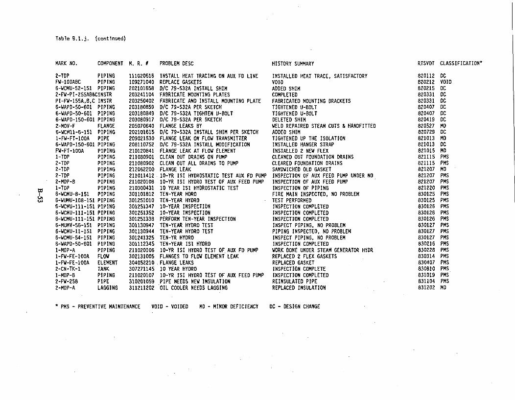
Table B.1.j. (continued)
MARK NO. COMPONENT M. R. # PROBLEM DESC HISTORY SUMMARY RTSVDT CLASSIFICATION*
2-TOP PIPINGFW-100ABC PIPING6-WCMU-52-151 PIPING2-FW-PI-255AB&CINSTRPI-FW-155AB,C INSTR6-WAPD-50-601 PIPING6-WAPD-50-601 PIPING6-WAPD-150-601 PIPING2-MOV-F FLANGE6-WCM11-5-151 PIPINGI-FW-FT-100A PIPE6-WAPD-150-601 PIPINGFW-FT-100A PIPING1-TDP PIPING2-TDP PIPING2-TDP PIPING2-TDP PIPING2-MDP-B PIPING1-TDP PIPING6-WCMU-8-151 PIPING6-WUMU-108-151 PIPING6-WCMU-111-151 PIPING6-WCMU-111-151 PIPING6-WCMU-111-151 PIPING6-MUMV-56-151 PIPING6-WCMU-11-151 PIPING6-WCMU-54-151 PIPING6-WAPD-50-601 PIPING1-MOP-A PIPINGl-FW-FE-100A FLOW1-FW-FE-lOOA ELEMENT2-CN-TK-1 TANK1-MDP-B PIPING2-FW-258 PIPE2-MDP-A LAGGING
111020616109271040202101658203241104203250402203180859203180849203080917205070640202101615209021530208110752210120841211080901211080902212062200211011412211020108210300431301101812301251010301251347301251352301251338301130947301130944301241325301112345211020106302131005304052210307271145211020107310201059311211202
INSTALL HEAT TRACING ON AUX FO LINEREPLACE GASKETSD/C 79-S32A INSTALL SHIMFABRICATE MOUNTING PLATESFABRICATE AND INSTALL MOUNTING PLATE0/C 79-532A PER SKETCHD/C 79-S32A TIGHTEN U-BOLTD/C 79-S32A PER SKETCHFLANGE LEAKS BYD/C 79-S32A INSTALL SHIM PER SKETCHFLANGE LEAK ON FLOW TRANSMITTERD/C 79-S32A INSTALL MODIFICATIONFLANGE LEAK AT FLOW ELEMENTCLEAN OUT DRAINS ON PUMPCLEAN OUT ALL DRAINS TO PUMPFLANGE LEAK10-YR ISI HYDROSTATIC TEST AUX FD PUMP10-YR ISI HYDRO TEST OF AUX FEED PUMP10 YEAR ISI HYDROSTATIC TESTTEN-YEAR HOROTEN-YEAR HYDRO10-YEAR INSPECTION10-YEAR INSPECTIONPERFORM TEN-YEAR INSPECTIONTEN-YEAR HYDRO TESTTEN-YEAR HYDRO TESTTEN-YR HYDROTEN-YEAR ISI HYDRO10-YR ISI HYDRO TEST OF AUX FD PUMPFLANGES TO FLOW ELEMENT LEAKFLANGE LEAKS10 YEAR HYDRO10-YR ISI HYDRO TEST OF AUX FEED PUMPPIPE NEEDS NEW INSULATIONOIL COOLER NEEDS LAGGING
INSTALLED HEAT TRACE, SATISFACTORYVOIDADDED SHIMCOMPLETEDFABRICATED MOUNTING BRACKETSTIGHTENED U-BOLTTIGHTENED U-BOLTDELETED SHIMWELD REPAIRED STEAM CUTS & HANDFITTEDADDED SHIMTIGHTENED UP THE ISOLATIONINSTALLED HANGER STRAPINSTALLED 2 NEW FLEXCLEANED OUT FOUNDATION DRAINSCLEARED FOUNDATION DRAINSSANDWICHED OLD GASKETINSPECTION OF AUX FEED PUMP UNDER NOINSPECTION OF AUX FEED PUMPINSPECTION OF PIPINGFIRE MAIN INSPECTED, NO PROBLEMTEST PERFORMEDINSPECTION COMPLETEDINSPECTION COMPLETEDINSPECTION COMPLETEDINSPECT PIPING, NO PROBLEMPIPING INSPECTED, NO PROBLEMINSPECT PIPING, NO PROBLEMINSPECTION COMPLETEDWORK DONE UNDER STEAM GENERATOR HYDRREPLACED 2 FLEX GASKETSREPLACED GASKETINSPECTION COMPLETEINSPECTION COMPLETEDREINSULATED PIPEREPLACED INSULATION
820112820212820215820331820331820407820407820419820527820729821013821013821015821115821115821207821207821207821220830125830125830126830126830126830127830127830127830216830228830314830407830810831019831104831202
DCVOIDDCDCDCDCDCDCMDDCMDDCMDPMSPMSMDPMSPMSPMSPMSPMSPMSPMSPMSPMSPMSPMSPMSPMSPMSPMSPMSPMSPMSMD
w
LA
* PMS - PREVENTIVE MAINTENANCE VOID - VOIDED MD - MINOR DEFICIENCY DC - DESIGN CHANGE

Table B.1.j. (continued)
MARK NO. COMPONENT M. R. I PROBLEM DESC HISTORY SUMMARY
FW-FT-lOOA PIPING 210130841 FLANGE LEAK VOID - TO BE DONE ON MR 13120815311-FW-FE-100A ELEMENT 312081531 FURMANITE STEAM LEAK SEAL WELDED PIPE PLUGS1-FW-153 BRACKET 403081501 TUBING TRAY BROKEN OFF REWELD SUPPORT2-FW-89 PIPE 403171638 REMOVE RESTRAINT AS NECESSARY REMOVED AND REPLACED RESTRAINT1-FW-FE-1O0A ELEMENT 404131324 BLANK CAVITATING VENTURI BLANKED VENTURI FOR HYDRO2-FW-PP-151 PIPE 406211048 REMOVE FURMANITE BOX, REPAIR VOID - TO BE COMPLETED ON WO 002510
* PMS - PREVENTIVE MAINTENANCE VOID - VOIDED MD - MINOR DEFICIENCY DC - DESIGN CHANGE
RTSVDT CLASSIFICATION*
831216 VOID831230 MD840313 MD840411 PMS840427 PMS840816 VOID

Table B.1.k. MAINTENANCE RECORDS FOR THE AUXILIARY FEEDWATER SYSTEM INSTRUMENTATION
MARK NO. COMPONENT M. R. # PROBLEM DESC HISTORY SUMMARY RTSVDT CLASSIFICATION*
1-FW-FE-IOOA INSTR1-FW-FE-100B INSTRI-FW-FT-IOOA INSTR1-FW-FT-IOOB INSTR1-FW-FT-1ODC INSTR2-FW-FT-200C INSTR1-FW-FE-100C INSTR1-FW-FE-IOOA INSTR1-FW-FE-200B INSTR1-FW-FE-200C INSTR1-FW-FE-200ABC INSTR1-FW-FE-100C INSTR1-FW-FE-200C INSTRI-FW-FE-IOOA INSTR1-FW-FT-IOOB TRANS1-FW-FE-200C INSTR1-FW-FE-IOOB INSTR2-FW-FT-200C TRANSMIT2-FW-FI-200C METER2-FW-FI-200B METER2-FW-FI-200C METER
10185490807061000
5050755505075650507574020800
105221547109300310112100548112100543202021305205191249212140636211240135308110249309062154308170805403191015402151134404011836404011840
CALIBRATE FLOW INDICATORINDICATES 175 GPM WITH PUMP OFFCALIBRATE TRANSMITTERCALIBRATE TRANSMITTERCALIBRATE TRANSMITTERREPLACE TRANSMITTERFLOW INDICATOR DOES NOT WORK-STUCKA STEAM GAUGE AUXILIARY FEED FLOWFLOW INDICATORFLOW INDICATORMETERS BOUNCINGMETER BOUNCING OFF ZEROFLANGE MISSING STUDCALIBRATE AS NECESSARYREPLACE TRANSMITTERERRATIC INDICATIONFEED FLOW SPIKES FI-FW-IOOBREDO THE ELECTRICAL SPLICESMETER INDICATES FLOWCHECK TRANSMITTER & METERCHECK TRANSMITTER & METER
CALIBRATED TRANSMITTERREPLACES TRANSMITTERCALIBRATED TRANSMITTERSCALIBRATED TRANSMITTERCALIBRATED TRANSMITTERREPLACED AND CALIBRATED TRANSMITTERWRONG VALVE LINE-UPCHECKED CALIBRATION, OPENED VALVEREPLACED INDICATORREPLACED INDICATORFILLED AND VENTED TRANSMITTERCALIBRATED TRANSMITTERINSTALLED STUD & NUTSCALIBRATED TRANSMITTERCHECKED LOOP AND XMTRTRANSMITTED, STABILIZEDREPLACED AND CALIBRATED TRANSMITTERVOID - NOT NEEDEDPERFORMED TRANSMITTER CALIBRATIONPERFORMED CALIBRATION 61PERFORMED CALIBRATION 62
780516780917800506800506800506800625810710811005820119820119820305821015821221830329830811830913830930840320840325840406840411
GAUGEGAUGEGAUGEGAUGEGAUGEGAUGEGAUGEGAUGEGAUGEGAUGEGAUGEGAUGEMDGAUGEGAUGEGAUGEGAUGEVOIDGAUGEGAUGEGAUGE
w
LA
* VOID - VOIDED MD - MINOR DEFICIENCY GAUGE - GAUGE REPLACEMENT OR CALIBRATION

Table B.2
Maintenance Records Broadly Classified as Failuresfor the Auxiliary Feedwater System
B-57 NUREG/CR-5378

Table B.2.a. MAINTENANCE RECORDS BROADLY CLASSIFIED AS FAILURES FOR THE AUXILIARY FEEDWATER SYSTEM TURBINE DRIVEN FEED PUMPS
MARK NO.
1-TDP1-TOPI-TDP1-TDP1-TDP1-TDP1-TDP2-TDP2-TDP1-TDP2-TDP2-TDP2-TOP2-TDP2-TOP2-TDP2-TDP1-TDP2-TDP1-TDP
2-TDP
COMPONENT
PUMPPUMPPUMPTURBPUMPPUMPINSTRPUMPPUMPPUMPGOVERNORPUMPPUMPPUMPPUMPBEARINGPUMPPMP GOVSWITCHPUMP
PUMP
M. R. # PROBLEM DESC
801010430 GROSS OIL-LOW DISCHARGE PRESSURE803030420 EXCESSIVE DISCHARGE PREE-PT15901030450 GOV VALVE WILL NOT CONTROL PUMP SPEED810040500 VARIOUS REPAIRS912172125 OUTBOARD PUMP BEARING THROWING OIL
1240708 OIL SEAL PACKING LEAK4131129 BROKEN CASE SWITCH11170730 OVERSPEED TRIP VALVE TRIPS
205081945 GOVERNOR SET AT 4060 RPM208132145 REPAIR OIL LEAK212061305 REPAIR FEEDBACK ARM302111050 PUMP TRIPS303101430 SET SCREW MISSING303181232 OVERSPEED TRIP304250400 OIL SEAL LEAKING306200726 REPLACE BEARING309271700 HIGH BEARING VIBRATIONS312311328 REPAIR GOVERNOR402240947 PUMP WILL NOT CUT OFF IN AUTO
14061 MECHANICAL LINKAGE BROKEN
23379 PUMP INOPERABLE, REPAIR
27017 P-REPAIR OIL LEAKS
4170 INVESTIGATE PUMP BEARING LEAK
40487 SPRING REPLACEMENT
MODE/MECHANISM(if applicable)HISTORY SUMMARY
RENEWED THRUST BEARING LININGSREDUCED SPEED OF PUMP AT GOVERNORFIXED SATISFACTORYREPAIRED AND TESTED GOVERNOR TRIP VALVERENEWED THRUST BEARINGRENEWED THRUST SHOEINSTALLED NEW SWITCHSTRAIGHTENED LINKAGERESET RPM TO 3880CHANGED THRUSTED SHAFT COLLAR JOURNALREINSTALLED SETSCREWADJUSTED OVERSPEED TRIPADJUSTED, DAMPERPUT SPRING BACK ON HOOKREPLACED BEARING AND THREAD SLOESREPLACED BEARING AND SHOESADJUSTED LINKAGEINSTALLED NEW SEATCHECKED SWITCHREINSERTED ROD AND CLOSED SOCKET ENDS AROUND BALLTIP.REMOVED INBOARD AND OUTBOARD BEARING CAPS-FOUND BOTH JOURNAL BEARINGS IN GOOD CONDITION-OUTBOARD THRUST BEARING -THRUST SHOES- WIPED ANDROLLED OVER WITH BABBITT. ALIGNMENTBAD BEARINGS/INSUFF. OIL FLOWREPLACED BEARINGS, THRUST BEARINGS, AND REPACKEDPUMP.BROKEN SLINGER/THRUSTINGREPLACED SLINGER, BEARINGS, WEAR RINGS, BALANCEGOVERNOR VALVE NOT OPEN ALL THE WAY, SUSPECT BADSPRING. REMOVED OLD SPRING AND REPLACED WITH NEWSPRING. OPS DID AN OPERABILITY TEST AND GOVERNORVALVE IS STILL NOT OPENING.
RTSVDT
780111780303790204790420791223800210800429801118820513820824821207830216830314830321830429830927831013840111840330850214
850819
CLASSSIFICATION*
FRFRFRFRFRFRFRFRFRFRFRFRFRFRFRFRFRFRFRFR
FR
U'
1-TDP
1-TDP
1-TDP
PUMP 860509 FR
PUMP
PUMP
860820
860907
FR
FR
* FR- POTENTIAL FAILURE TO RUN

Table B.2.a.
MARK NO.
1-TOP
I-TDP
1-TDP
1-TDP
(continued)
COMPONENT
PUMP
PUMP
PUMP
PUMP
M. R. #
41325
40454
40488
40491
PROBLEM DESC
OPEN,INSPECT,REPAIR GOV VALVE
ADJUST GOVERNOR VALVE LINKAGE
REPAIR OVERSPEED TRIP
VALVE LINKAGE ADJUSTMENT
MODE/MECHANISM(if applicable)HISTORY SUMMARY
VALVE GOV LEAK THRU/STEAM CUT SEATSREMOVE LINKAGE AND VALVE FORM SYSTEM. FOUND BODYTO BE STEAM CUT ON SEATS. AS WE REMOVED BUSHINGLINKAGE/IMPROPER SETDISCONNECTED LINKAGE L2 AND LI, REMOVED PIN FROMSHAFT LI, SET STEAM GOVERNOR VALVE, LOOSENEDFISHER REGULATING SPRING AND SET AT 3/8.VALVE CHECKED FOR FREEDOM OF MOVEMENT, FOUND TO BESTICKING APPROXIMATELY 50X IN THE CLOSED POSITION.VALVE DISASSEMBLY REVEALED HEAVY WEAR AND SOMESTEAM CUTS TO GUIDE.WE FOUND THE LINKAGE OUT OF ADJUSTMENT ANDGOVERNOR LEVER HAD EXCESS WEAR. WE REMOVED THE OLDLINKAGE AND GOVERNOR LEVERS,REPLACING SAME WITHNEW LEVERS. THE NEW LEVERS HAD
RTSVDT CLASSSIFICATION*
860927 FR
860930 FR
860930 FR
860930 FR
w'0

Table B.2.b. MAINTENANCE RECORDS BROADLY CLASSIFIED AS FAILURES FOR THE AUXILIARY FEEDWATER SYSTEM MOTOR DRIVEN FEED PUMPS
MODE/MECHANISM(if applicable)HISTORY SUMMARYMARK NO. COMPONENT M. R. # PROBLEM DESC RTSVDT CLASSIFICATION*
2-MOP-B2-MDP-A2-MDP-A2-MDP-A2-MDP-B1-MDP-A2-MDP-B1-MDP-A1-MDP-A1-MDP-B1-MDP-A1-MDP-A1-MDP-B2-MDP-B1-MDP-B1-MDP-A1-MDP-A1-MDP-A1-MOP-A2-MOP-A2-MDP-A2-MDP-B
PUMPPUMPPUMPPMP MTRHXHXPUMPPUMPHXHT EXCHPUMPINSTRINSTRPUMPPUMPMOTORPUMPPUMPBREAKERMOTORELAYPUMP
PUMP
PUMPPUMP
902050137902050130902131327902111545901081400912211400
722215512270930
101130847101130846101291401105220735105220737
418073111111034020320051920326130021005052830607212530921150031006010515531
PUMP START NOT SATISFACTORYPUMP START NOT SATISFACTORYOIL COOLER END BELL CRACKEDMOTOR HEATER NOT WORKINGREPAIR HEATERSTUBE LEAKPUMP WILL NOT AUTO STARTDAMAGE WAS CAUSED BY FREEZINGREPAIR BROKEN LUBE OIL COOLERHEAD-ON COOLER BROKENLUBE OIL COOLER BROKENPUMP STARTED IN 62PUMP STARTED IN 66NO OIL PRESSUREBEARING VIBRATION PUMPMOTOR WAS SPRAYED WITH STEAMDETERMINE FAILURE OF PUMPFW LEAK UPSTREAM OF LUBE OIL COOLERRELAY DROP ON A PHSE INSTREPAIR OR REPLACE MOTOR HEATERREPLACE 2-MDP-A RELAY2-MOP-B CHECK HEATERS
TIME DELAY TESTED SATISFACTORYTIME DELAY TESTED SATISFACTORYREPAIRED COOLERINSTALLED NEW HEATERS - TESTED SATINSTALLED NEW HEATERS - TESTED SATCOMPLETED REPAIRSTESTED SATISFACTORYFIXED SPLIT CASINGREPLACED GASKET AT HEADREMOVED HEAD, BRAZED TOGETHERREPAIRED LUBE OIL COOLER HEADERRESET AGASTATSRESET AGASTATSPACKED STUDS CHECKED OIL PRESSUREREPLACED INBOARD BEARINGPERFORMED PI CURVEBREAKER CLOSED SATISFACTORYREPAIRED LEAK ON 3/4 PIPEMOTOR BRIDGED + MEGGEREDREPLACED HEATERREPLACED RELAY COIL FAILEDREMOVED BAD HEATER FROM MOTOR -NO STOCK ITEM-HEATER ORDERED 3/25/85. REPLACED DEFECTIVEHEATER, TEST SAT.PERFORM PI CURVE ON MOTOR WINDINGS. TESTEDSATISFACTORY.PERFORMED PI CURVE ON MOTOR WINDING.LEAK/OIL IN WATER/WATER IN OIL.REMOVED LUBE OIL COOLER AND HYDRO WITH 100 PSISERVICE AIR. NO LEAKAGE EVIDENT.
790207790209790324790910790910791223800725810101810114810114810201810522810522810616820309820320820330821014830611831006831012850712
FSFSFRFSFSFRFSFRFRFRFRFSFSFRFRFSFSFRFSFSFSFS
to
I-MDP-A
1-MDP-B2-MOP-A
39854 1-FW-M-3A MOTOR WET
39853 1-FW-M-3B MOTOR WET51214 REPLACE/REPAIR LUBE OIL COOLER
860826 FS
860826 FS870331 FR
* FR- FAILURE TO RUN FS - IYNCIPIENT FAILURE TO START

Table B.2.b. (continued)
MARK NO.
1-MDP-B
2-MDP-B
COMPONENT M. R. #
PUMP 49509
PROBLEM DESC
P-REPLACE MOTOR HEATERS
-P- REPLACE LO COOLER
MODE/MECHANISM(if applicable)HISTORY SUMMARY
HEATERS BAD/AGE, REPLACED HTRSMEGGERED 14 MEGOHMS AMPS .8 1.1 WORKED SAT.CHANGED OVERLOADS INSTALLED 1018L.LEAKING OIL/INSTALL NEW COOLER. AS FOUND- COOLER LEAKING.WORK PERFORMED-INSTALLED NEW OIL COOLER. ASLEFT-TEST SAT.
RTSVDT CLASSIFICATION*
870522 FS
870807 FRPUMP 52414
* FR- FAILURE TO RUN FS - IYNCIPIENT FAILURE TO START
w
61

Table B.2.c. MAINTENANCE RECORDS BROADLY CLASSIFIED AS FAILURES FOR THE AUXILIARY FEEDWATER SYSTEM 3-INCH MOTOR OPERATED VALVES
MODE/MECHANISM(if applicable)HISTORY SUMMARYMARK NO. COMPONENT M. R. I PROBLEM DESC RTSVDT CLASSIFICATION*
2-MOV-D1-MOV-F1-MOV-B2-MOV-A1-MOV-E1-MOV-E2-MOV-E2-MOV-F2-MOV-D2-MOV-D2-MOV-B2-MOV-B1-MOV-F1-MOV-E1-MOV-A1-MOV-F2-MOV-C1-MOV-F1-MOV-F1-MOV-F1-MOV-F2-MOV-BDF1-MOV-E1-MOV-D1-MOV-C2-MOV-F2-MOV-C1-MOV-D2-MOV-F2-MOV-F1-MOV-D1-MOV-D1-MOV-D1-MOV-F2-MOV-B
MOVMOVMOVMOVMOVMOVMOVVALVEVALVEMOVMOVMOVMOVMOVMOVMOVVALVEMOVMOVNOVMOVCONTROLMOVVALVEMOVVALVEVALVEMOVMOVVALVEVALVEVALVEVALVEMOVMOV
804061950806022200806302330810110135
106191010618251062046429123042114295281601823094011011730
9061808421061004201031108401100117501111215192081407002081201352101306022101401012121720113031002153040720303042305213042401453042306593051118303070506104011316054061403004061911354061904081389302140
WON'T STAY CLOSEDTORQUE SWITCH BADBREAKER WILL NOT RESET AND VALVEDID NOT AUTO OPENMOTOR HOUSING SHATTEREDDISCONNECT AND RECONNECT POWERREMOVE MOV FOR USE ON UNIT 1DISASSEMBLE LIMITORQUE FOR INSPECTIONVALVE OPEN WHEN SHOULD BE SHUTMOV IS SHUT BREAKER IS OPENTORQUE SWITCH PROBLEMMOV WILL NOT OPERATELEAKS THRUCHECK CONTROL CIRCUIT FOR POSS GROUNDVALVE STIFFMOV INDICATE CLOSED LOCALLYREPAIR GEAR BOXCHANGE LIMITORQUEVALVE WILL NOT OPERATE BREAKER THERMVALVE WILL NOT FULLY CLOSEMOV WILL NOT CLOSEWHEN LO-LO S/G LEVEL WAS RECEIVEDAGASTAT CONTACT IS STICKINGVALVE OPENS BUT WILL NOT CLOSEVALVE MOTOR IS LOOSEVLV WHEN CLOSED CAME BACK OPENDRIVE MECHANISM BROKENVALVE CLOSESMOV WONT STAY CLOSEDVALVE OPENSLIMITS NOT WORKINGREPAIR/REPLACE GEAR ASSEMBLYVALVE WON'T CLOSE OR OPEN1-MOV-F BREAKER TRIPPEDEXCESSIVE STROKE TIME
ADJUSTED SWITCHREPLACED TORQUE SWITCHREPAIRED - TESTED SATISFACTORYCHECKED OUT CONTROL CIRCUIT - OKREPLACED WITH LIMTORQUE FROM MOV 251MOV REPLACED ON UNIT ICOMPLETEDUNSTUCKVALVE OPERATES AS DESIGNEDADJUSTED SWITCHREPAIRED BROKEN WIREREPAIRED LEADS, TEST SWITCH SATISFACTORYNEEDED TO BE WIRED UPCOMPLETED AS PER EMP-C-MOV-63COMPLETEDCOMPLETED - VALVE DOES NOT WORK SATRENEWED BEVEL GEARINSTALLED NEW LIMITORQUEDISCONNECTED/RECONNECTED SATISFACTORYDISCONNECTED/RECONNECTED MOV, SATREMACHINED SEAT RINGREWIRED BREAKERS ASADJUSTED MICROSWITCHADJUSTED LIMITSDISCONNECTED ANDVALVE CYCLED SATREPLACED DESTROYED MOV WITH NEW MOVCYCLED VALVECYCLED SATAGASTAT STICKINGREPLACED LIMIT SWITCH, GEAR WORNINSPECTED, FOUND LIMITOROUE SATREPLACED LIMITS, DISCONNECTEDBRIDGED AND MEGGERED SATISFACTORY, CYCLED SEVERALDISASSEMBLE VALVE AND INSPECT PARTS
780407780605780706781015800107800219800323800509800513800602800826801104810325810611810618811001811207820814820814821014821018821218830313830411830423830424830426830520830819840412840614840620840620850213850620
PGPGPGPGPGPGPGPGPGPGPGPGPGPGPGPGPGPGPGPGPGPGPGPGPGPGPGPGPGPGPGPGPGPGPG
w
* PG - PLUGGING FAILURE

Table B.2.c. (continued)
MARK NO.
2-MOV-D
2-MOV-F
1-MOV-D
2-MOV-A1-MOV-D
1-MOV-D
2-MOV-D
1-MOV-D
1-MOV-E
2-MOV-C
COMPONENT
MOV
MOV
MOV
MOVMOV
MOV
MOV
MOV
MOV
M. R. I
02382
02333
22962
2054029885
PROBLEM DESC
INVESTIGATE STROKE TIME
INVESTIGATE STROKE TIME
1-MOV-D INVESTIGATE TRIP
2-MOV-A WONT XFER CONTRINVESTIGATE/REPAIR MOV
29920 E-INVESTIGATE/REPAIR ASREQUIRED
37688 2-MOV-D WILL NOT OPEN
45967 INVESTIGATE/REPAIR AS NEEDED
49801 INVESTIGATE MALFUNCTION
MODE/MECHANISM(if applicable)HISTORY SUMMARY
DISASSEMBLED VALVE CLEAN AND INSPECTED INTERNALSREASSEMBLED VALVE WITH NEW BONNET GASKET. STEM,PLUG AND ROTATE REPACKED VALVEDISASSEMBLED VALVE REPLACED STEM, DISC TORQUE KEY,GASKET DISC WASHER-100 PERCENT BLUE CHECKREASSEMBLED VALVEWORKED WITH OPERATORS AND CYCLED VALVE;SATISFACTORY,NO PROBLEMS FOUND (OPEN 2.5 AMPS,CLOSED 2.5 AMPS).REPLACED COIL ON LATCHING RELAY OLD COIL BURNT UPRESET THERMO OVERLOADS, TURNED BREAKER ON ANDVALVE AUTOMATICALLY WENT OPEN DRAWING 2.7 AMPS.DREW 2.7 ALL THE WAY CLOSED, THEN DREW 11.3 AMPS.WE THINK THE TORQUE SWITCH IS BROKEN.AS FOUND - DISASSEMBLED LIMITORQUE, FOUND NOINTERNAL DAMAGE OF COMPONENTS. GREASE WAS VERYHARD, CLEANED ALL PARTS AND HOUSING,CHANGED OUTGREASE WITH EP-O, AND REASSEMBLED.FAILURE/VALVE WOULD NOT OPER.AUX. CONTACTS STUCK. CHECKED AND FOUND AUX.CONTACTS WERE STUCK OPERATED AND CHECKED SAT.ASSISTED OPERATORS IN OPENING VALVE FULLY FROMMCC. VALVE WENT FULL OPEN, FULL CLOSE WITH PROPERINDICATION. WORK PERFORMED ON WO 047506, 1/8/87.VALVE WOULEN'T OPEN/AUXILIARY OPENINTERLOCK STUCK ON OPENING CIRCUIT. REPLACEDCONTACTOR 2/18/87, CHECKED SATISFACTORY.TIMES. FLA 2.4 ACTUAL, Ti 2.4, T2 2.4, AND T3 2.4OKAY.SPRING PACK DISASSEMBLED 12/30/86. S/N 347490.INSTALLED SPRING PACK ONLY. LEFT WITH MOVAT.WORK WAS PERFORMED BY MOVAT.
RTSVDT
850620
850620
850814
851029860128
CLASSIFICATION*
PG
PG
PG
PGPG
860131 PG
860715
861123
870219
PG
PG
PG
MOV 46218 REPAIR VALVE 870225 PG
* PG - PLUGGING FAILURE

Table B.2.d. MAINTENANCE RECORDS BROADLY CLASSIFIED AS FAILURES FOR THE AUXILIARY FEEDWATER SYSTEM 6-INCH MOTOR OPERATED VALVES
MODE/MECHANISM(if applicable)HISTORY SUMMARYMARK NO. COMPONENT M. R. # PROBLEM DESC RTSVDT CLASSIFICATION*
2-MOV-J2-MOV-J2-MOV-I2-MOV-I2-MOV-J2-MOV-J1-MOV-G1-MOV-G2-MOV-I2-MOV-I2-MOV-J2-MOV-J1-MOV-G1-MOV-H
1-MOV-H
VALVENOVNOVNOVNOVVALVENOVNOVVALVEVALVEVALVEVALVENOVMOV
810030726812040631
723142580509298122234
1011312006120630
1121204203041916353042315003041916373042314272335030387
WILL NOT OPERATETHERMALS OUT WON'T OPENVALVE IS BINDING UPREPLACE LIMITORQUEVALVE WILL NOT COME FULL OPENVALVE BINDS UNABLE TO CLOSEVALVE WILL NOT OPENVALVE WILL NOT CYCLEVLV CYCLES HI AMPS ON MTRMOV-I WILL NOT OPENVLV CYCLES HI AMPS ON MTRMOV-J WILL NOT OPENINVESTIGATE/REPAIRMOV-H WILL NOT STROKE
MEG BRIDGED AND TESTED SATISFACTORY 781006 FCCLEANED, CHECKED MOTOR - TEST SAT 781204 FCREPAIRED VALVE 800801 FCREPAIRED LIMITORQUE OPERATOR 800807 FCNO PROBLEMS FOUND 800814 FCCLEANED STEM THREADS 810120 FCCOMPLETE 810423 FCADJUSTED LIMITS ON MOV-FW-160A, SAT 811212 FCADJUSTED PACKING 830423 FCCLEANED TORQUE SWITCH 830423 FCADJUSTED PACKING 830423 FCADJUSTED TORQUE SWITCH 830423 FCREMOVED MOUNTING BOLTS FROM TORQUE SWITCH AND 850823 FCCYCLED VALVE SEVERAL TIMES, OPENED TI 2.4, T2 2.8, 860211 FCAND T3 2.9;CLOSED Ti 2.8, T2 2.6, T3 2.6, FOUND NO PROBLEM ATTHIS TIME.MOTOR HOIST/BEARINGS BAD 860807 FCDISCONNECTED MOTOR, REPLACED BEARINGS, RECONNECTEDAND CYCLED SATISFACTORY. RECONNECTED MOTOR TEST, RANSATISFACTORY.
MOV 39300 1-MOV-H REPLACE BEARINGS
* FC - CROSS-CONNECTING FAILURE

Table B.2.e MAINTENANCE RECORDS BROADLY CLASSIFIED AS FAILURES FOR THE AUXILIARY FEEDWATER SYSTEM 3-INCH CHECK VALVES
MODE/MECHANISM(if applicable)HISTORY SUMMARYMARK NO. COMPONENT M. R. # PROBLEM DESC RTSVDT CLASSIFICATION*
1-CV-J1-CV-H1-CV-I1-CV-I1-CV-H1-CV-J2-CV-H2-CV-I2-CV-J2-CV-H2-CV-I2-CV-J1-CV-H2-CV-J2-CV-I2-CV-H1-CV-H1-CV-I
VALVEVALVEVALVEVALVEVALVEVALVEVALVEVALVEVALVEVALVEVALVEVALVEVALVEVALVEVALVEVALVEVALVEVALVE
410200041509164150915
109210813109210811109210815110290942110290938110290941312071039312071040312071041312160902403131437403131441401031301404080900
2385
INSPECT VALVEINSPECT INTERNALS AND REPAIRINSPECT INTERNALS AND REPAIROVERHAUL VALVEOVERHAUL VALVEOVERHAUL VALVEREPLACE VALVEREPLACE VALVEREPLACE VALVECHECK VALVE LEAKS THROUGHCHECK VALVE LEAKS THROUGHCHECK VALVE LEAKS THROUGHLEAKS THROUGHOPEN & INSPECT VALVEOPEN AND INSPECT VALVEREPAIR TO ORIGINAL FURMANITEDCHECK VALVE LEAKS THROUGHOVERHAUL VALVE
REPAIRED VALVEREPAIRED VALVEINSPECTED AND REPAIRED VALVECOMPLETED AS ABOVECOMPLETED AS ABOVECOMPLETED AS ABOVEREPLACED FW CHECK VALVE 2-CV-HREPLACED CHECK VALVEREPLACED CHECK VALVE 2-CV-JLAPPED VALVE DISH TO SEATCUT OUT SEAL WELDLAPPED SEATSCLEANED VALVE & LAP SETCUT OUT VALVE, SHIP TO CRANE FOR REPAIRCUT OUT VALVE, SHIP TO CRANE FOR REPAIRSHIPPED VALVE TO CRANE FOR REPAIRSOVERHAULED CHECK VALVEDISASSEMBLED VALVE AND INSPECTED INTERNALS. LAP
800415800417800424810930810930810930811205811205811215831214831221831221840107840406840406840406840509841210
LKLKLKLKLKLKLKLKLKLKLKLKLKLKLKLKLKLK
SEAT AND DISC GOT 100% BLUEING. REMOVED 2-PINRETAINIG PLUGS. INSTALLED PIN, RETAINING PLUGSAND WELDED.
* LK - UNDETECTED LEAKAGE FAILURE

Table B.2.f. MAINTENANCE RECORDS BROADLY CLASSIFIED AS FAILURES FOR THE AUXILIARY FEEDWATER SYSTEM 4-INCH CHECK VALVES
MODE/MECHANISM(lf applicable)HISTORY SUMMARYMARK NO. COMPONENT M. R. I PROBLEM DESC RTSVDT CLASSIFICATION*
1-CV-C1-CV-B2-CV-C2-CV-C2-CV-C2-CV-C2-CV-C2-CV-C
VALVEVALVEVALVEVALVEVALVEVALVEVALVEVALVE
30429140230429140030504050931118113731120131040127092540307093301799
LEAKS BACK THROUGHLEAKS BACK THROUGHCHECK VALVECHECK VALVE LEAKS BY2-CV-C IS LEAKING BYRESEAT VALVELEAKS THROUGH RESEATOVERHAUL VLV.
REPAIR VALVEREBUILT VALVELAPPED SEAT REPLACED NUTSPERFORMED CLEANLINESS INSPECTIONINSPECTED VALVE INTERNALSLAPPED SEAT AND DISCVALVE CHECKED 2-CV-CDISASSEMBLE VALVE LAPPED SEAT AND DISC, HAVE100% BLUEING.
830504830525830926831119831120840128840313841218
LK/00LK/00LK/00LK/OOLK/OOLK/OOLK/00LK/0O
* LK - UNDETECTED LEAKAGE FAILURE 00 - BACKFLOW FAILURE

Table B.2.g. MAINTENANCE RECORDS BROADLY CLASSIFIED AS FAILURES FOR THE AUXILIARY FEEDWATER SYSTEM 6-INCH CHECK VALVES
MODE/MECHANISM(if applicable)HISTORY SUMMARYMARK NO.
2-CV-A2-CV-F2-CV-G1-CV-A2-CV-D2-CV-F2-CV-A2-CV-F2-CV-D2-CV-D2-CV-E2-CV-F2-CV-F2-CV-F2-CV-F2-CV-F2-CV-E
2-CV-D
2-CV-E
I-CV-A
1-CV-A
1-CV-A
COMPONENT M. R. # PROBLEM DESC RTSVDT CLASSIFICATION*
VALVEVALVEVALVEVALVEVALVEVALVEVALVEVALVEVALVEVALVEVALVEVALVEVALVEVALVEVALVEVALVEVALVE
30113115030421231130421231230429140130113100230113100431120152031207105540327100040403113040327084040407215240403154040407092840408100040402132001222
OVERHAUL LEAK THROUGH CHECK VALVELEAKS THRULEAKS THRULEAKS BACK THROUGHOVERHAUL LEAKS THROUGHOVERHAUL LEAKS THROUGHCHECK VALVE LEAKING BACK THROUGHCHECK VALVE LEAKS THROUGHOPEN & INSPECT VALVELEAKS THROUGHOPEN AND INSPECT VALVEVALVE LEAKS THROUGHLEAKS THROUGHVALVE LEAKS THROUGHREMOVE BONNET & INSPECTVALVE LEAKS BYOVERHAUL VLV.
VALVE 25924 -PS- OVERHAUL VALVE
VALVE 30558 -P,S- INSPECT/REPAIR VALVE
VALVE 49606 REPAIR LEAK
VALVE 49058 P-REPAIR CHECK VALVE
VALVE 53704 P-INVESTIGATE, REPAIR CHECKVALVE
OVERHAULED VALVELAPPED SEAT + DISKLAPPED DISK + SEATREWORKED VALVELAPPED SEATSGROUND SEAT AND DISCONNECTEDDISASSEMBLED VALVEINSPECTED VALVE INTERNALSOPENED VALVE FOR INSPECTION, FOUNDREWORKED VALVEHAD DISC MACHINED, LAPPED DISCINSPECTED VALVE AND LAPPEDOVERHAULED INTERNALSRELAPPED' & TESTED PRIOR TO ASSEMBLYOPENED AND INSPECTED VALVEMACHINED TEN FROM DISC 100%DISASSEMBLE VALVE AND INSPECT INTERNALS LAP SEATAND DISC AS NECESSARY TO GET 100% BLUEINGDISSASEMBLED VALVE GROUND SEAT ON FLAPPER BLUEDSEATING SURFACES. REASSEMBLED VALVE TORQUED TO368 FR LB. SEAL WELD PLUG INSIDE OF VALVE.REWORK VALVE/UNKTACK WELDS ON PIN PLUG TO BE GROUND OFFTHEN REWELDED AFTER VALVE WORK COMPLETE. OPENVALVE AND INSPECTED INTERNALS. FOUND 1/16-LEAKING THROUGH/NORMAL WEARAS FOUND - CHECK VALVE SUPPOSEDLY LEAKING BY.WATER RUNNING OUT OF DRAIN VALVE BETWEEN PUMPAND CHECK VALVE. REMOVED CAP ONLEAK BY SEAT/WORN DISCDISASSEMBLED VALVE BLUED SEAT. SEAT LOOKED OK.DISC WORN OUT AND PITTED. LAPPED DISC BLUED 100%.REASSEMBLED VALVE.LEAK/WEARAS FOUND - VALVE SEAT CORRODED AND SLIGHTLY PITTED,WORK PERFORMED. REMOVED BONNET PIN AND DISK,CLEANED VALVE PIN AND BONNET.
830117830426830426830520830815830926831129831213840406840406840406840408840408840408840408840408841114
LK/O0LKLKLK/DOLKLKLK/OOLKLKLKLKLKLKLKLKLKLK
861202 LK
870104 LK
870214 LK/OO
870214 LK/O0
870528 LK/DO
* LK - UNDETECTED LEAKAGE FAILURE 00 - BACKFLOW FAILURE

Table B.3
Maintenance Records Broadly Classifiedas Failures for the Auxiliary Feedwater System,
Rewritten Format
B-69 B-69 ~~~NUREG/CR-5378

Table B.3.a. MAINTENANCE RECORDS BROADLY CLASSIFIED AS FAILURES FOR THE AUXILIARY FEEDWATER SYSTEM TURBINE DRIVEN FEED PUMPS, REWRITTEN FORMAT
MARK NO. COMPONENT M. R. I PROBLEM/REPAIR SUMMARY RTSVDT CLASS*
1-TOP PUMP 801010430 THE LUBRICATING OIL PRESSURE FAILED LOW RESULTING IN BEARING DAMAGE, REPLACED THRUST BEARING LINING. 780111 FR
1-TDP PUMP 803030420 THE PUMP DISCHARGE PRESSURE WAS HIGH, ADJUSTED THE GOVERNOR TO REDUCE THE PUMP SPEED AND THUS 780303 FRDISCHARGE PRESSURE.
1-TDP PUMP 901030450 THE GOVERNOR VALVE WAS NOT CONTROLLING PUMP SPEED, GOVERNOR WAS REPAIRED IN SOME MANNER. 790204 FR
1-TOP TURB 810040500 VARIOUS NON-SPECIFIED REPAIRS WERE MADE TO THE PUMP, THE PUMP WAS RETURNED TO SERVICE. 790420 FR
1-TDP PUMP 912172125 THE OUTBOARD PUMP BEARING WAS THROWING ENOUGH OIL THAT IT WAS NECESSARY TO RENEW THE THRUST BEARING. 791223 FR
1-TDP PUMP 1240708 AN OIL SEAL PACKING LEAK WAS LARGE ENOUGH THAT IT WAS NECESSARY TO RENEW THE THRUST BEARING SHOE. 800210 FR
1-TDP INSTR 4131129 A BROKEN CASE SWITCH ASSOCIATED WITH THE DISCHARGE PRESSURE TRIP WAS FOUND AND REPLACED. 800429 FR
2-TOP PUMP 11170730 DEFICIENCIES IN THE OVERSPEED TRIP VALVE CAUSED A PUMP:TRIP, THE LINKAGE WAS STRAIGHTENED. 801118 FR
2-TOP PUMP 205081945 THE GOVERNOR WAS CONTROLLING PUMP SPEED HIGH AT 4060 RPM. IT WAS RESET TO CONTROL AT AN RPM OF 3880. 820513 FR
1-TOP PUMP 208132145 AN OIL LEAK WAS LARGE ENOUGH THAT IT WAS NECESSARY TO REPLACE SOME BEARINGS. 820824 FR
2-TDP GOVERNOR 212061305 THE FEEDBACK ARM OF THE GOVERNOR WAS NOT WORKING CORRECTLY, A SETSCREW WAS INSTALLED. 821207 FR
2-TDP PUMP 302111050 THE OVERSPEED TRIP CAUSED CAUSED INAPPROPRIATE PUMP TRIPS.. THE OVERSPEED TRIP WAS CORRECTLY ADJUSTED. 830216 FR
2-TOP PUMP 303101430 THE SET SCREW WAS FOUND MISSING FROM THE FEEDBACK ARM. IT WAS REPLACED AND THE ARM ADJUSTED CORRECTLY. 830314 FR
2-TOP PUMP 303181232 FAILURE OF THE OVERSPEED TRIP SPRING TO STAY ENGAGED LED TO A PUMP TRIP, THE SPRING WAS REINSTALLED. 830321 FR
2-TOP PUMP 304250400 AN OIL SEAL LEAK WAS LARGE ENOUGH THAT IT WAS NECESSARY TO REPLACE SOME BEARINGS AND THRUST SHOES. 830429 FR
2-TDP BEARING 306200726 IT WAS NECESSARY, FOR SOME UNSPECIFIED REASON. TO REPLACE THE BEARINGS AND SHOES. 830927 FR
* FR - FAILURE TO RUN

Table B.3.a. (continued)
MARK NO. COMPONENT M. R. # PROBLEM/REPAIR SUMMARY RTSVDT CLASS*
2-TDP PUMP 309271700 HIGH BEARING VIBRATIONS REQUIRED THE ADJUSTMENT OF THE PUMP TO MOTOR COUPLING. 831013 FR
1-TDP PMP GOV 312311328 THE GOVERNOR WAS FOUND TO BE DAMAGED AND THE SEAT WAS REPLACED. 840111 FR
2-TDP SWITCH 402240947 THE DISCHARGE PRESSURE SWITCH WAS NOT AUTOMATICALLY TRIPPING THE PUMP. THE SWITCH WAS REPAIRED. 840330 FR
1-TOP PUMP 14061 THE MECHANICAL LINKAGE WAS FOUND TO BE BROKEN AND WAS REPAIRED. 850214 FR
2-TDP PUMP 23379 PUMP WAS SAID TO BE INOPERABLE, OUTBOARD THRUST SHOE WAS FOUND WIPED. IT WAS REPLACED. 850819 FR
1-TDP PUMP 27017 INSUFFICIENT OIL FLOW RESULTED IN BEARING DAMAGE, THE BEARINGS WERE REPLACED. 860509 FR
1-TDP PUMP 4170 THE BEARINGS WERE DAMAGED AS A RESULT OF A BAD SLINGER, THE SLINGER AND BEARINGS WERE REPLACED. 860820 FR
1-TOP PUMP 40487 THE GOVERNOR VALVE WOULD NOT OPEN, SPRING WAS REPLACED BUT THIS DID NOT HELP. 860907 FR
1-TDP PUMP 41325 GOVERNOR WAS REMOVED AND OVERHAULED BECAUSE POOR OPERATION. 860927 FR
(THIS EVENT SHOULD WAS COMBINED WITH RECORD 40487)
t 1-TOP PUMP 40450 ADDITIONAL GOVERNOR WORK COMBINED WITH RECORD 40487. 860930 FR
1-TOP PUMP 40488 ADDITIONAL GOVERNOR WORK COMBINED WITH RECORD 40487. 860930 FR
1-TDP PUMP 40491 ADDITIONAL GOVERNOR WORK COMBINED WITH RECORD 40487. 860930 FR
* FR - FAILURE TO RUN FS - FAILURE TO START
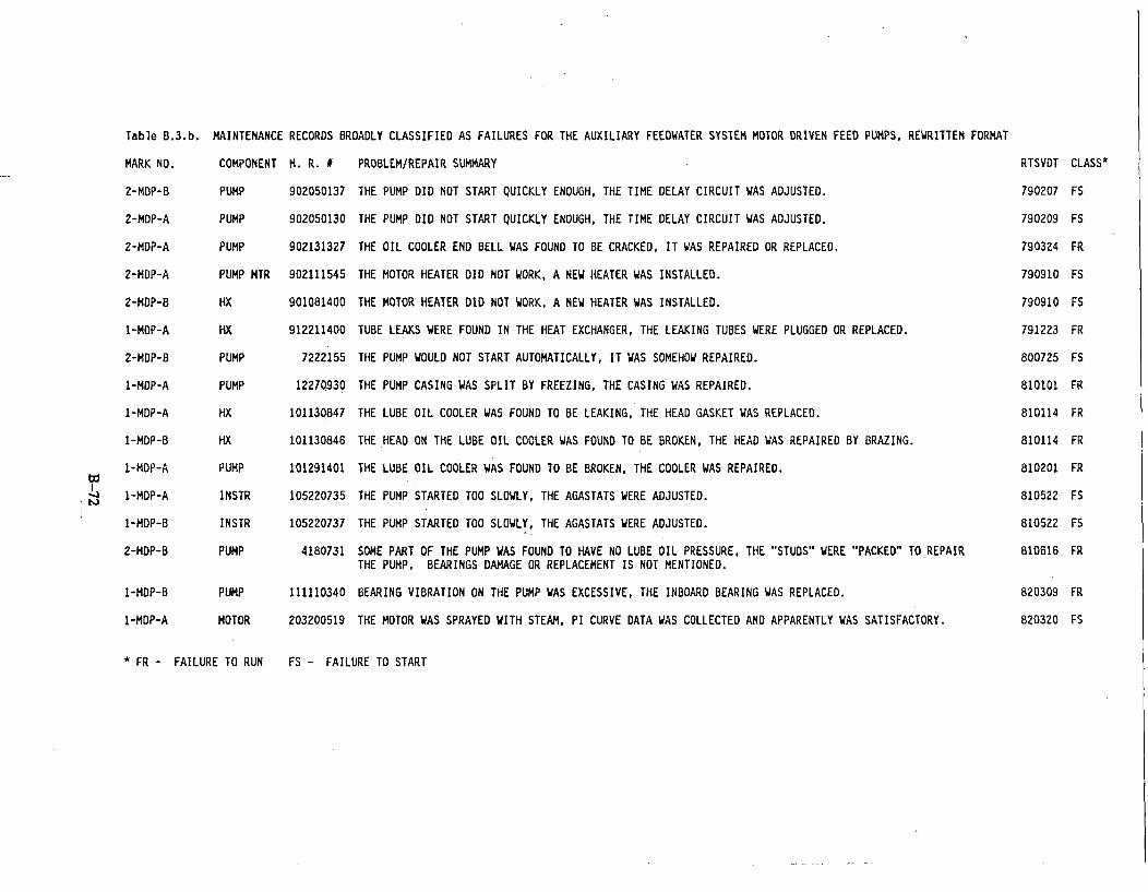
Table B.3.b. MAINTENANCE RECORDS BROADLY CLASSIFIED AS FAILURES FOR THE AUXILIARY FEEDWATER SYSTEM MOTOR DRIVEN FEED PUMPS, REWRITTEN FORMAT
MARK NO.
2-MOP-B
2-MOP-A
2-MDP-A
2-MDP-A
2-MDP-B
1-MOP-A
2-MDP-B
1-MDP-A
1-MDP-A
1-MDP-B
1-MOP-Awt 1-MDP-A
1-MDP-B
2-MDP-B
1-MDP-B
1-MDP-A
COMPONENT
PUMP
PUMP
PUMP
PUMP MTR
HX
HX
PUMP
PUMP
HX
HX
PUMP
INSTR
INSTR
PUMP
PUMP
MOTOR
M. R. #
902050137
902050130
902131327
902111545
901081400
912211400
7222155
12270930
101130847
101130846
101291401
105220735
105220737
4180731
111110340
203200519
PROBLEM/REPAIR SUMMARY
THE PUMP DID NOT START QUICKLY ENOUGH, THE TIME DELAY CIRCUIT WAS ADJUSTED.
THE PUMP DID NOT START QUICKLY ENOUGH, THE TIME DELAY CIRCUIT WAS ADJUSTED.
THE OIL COOLER END BELL WAS FOUND TO BE CRACKED, IT WAS REPAIRED OR REPLACED.
THE MOTOR HEATER DID NOT WORK, A NEW HEATER WAS INSTALLED.
THE MOTOR HEATER DID NOT WORK, A NEW HEATER WAS INSTALLED.
TUBE LEAKS WERE FOUND IN THE HEAT EXCHANGER, THE LEAKING TUBES WERE PLUGGED OR REPLACED.
THE PUMP WOULD NOT START AUTOMATICALLY, IT WAS SOMEHOW REPAIRED.
THE PUMP CASING WAS SPLIT BY FREEZING, THE CASING WAS REPAIRED.
THE LUBE OIL COOLER WAS FOUND TO BE LEAKING, THE HEAD GASKET WAS REPLACED.
THE HEAD ON THE. LUBE OIL COOLER WAS FOUND TO BE BROKEN, THE HEAD WAS REPAIRED BY BRAZING.
THE LUBE OIL COOLER WAS FOUND TO BE BROKEN, THE COOLER WAS REPAIRED.
THE PUMP STARTED TOO SLOWLY, THE AGASTATS WERE ADJUSTED.
THE PUMP STARTED TOO SLOWLY, THE AGASTATS WERE ADJUSTED.
SOME PART OF THE PUMP WAS FOUND TO HAVE NO LUBE OIL PRESSURE, THE "STUDS" WERE "PACKED" TO REPAIRTHE PUMP, BEARINGS DAMAGE OR REPLACEMENT IS NOT MENTIONED.
BEARING VIBRATION ON THE PUMP WAS EXCESSIVE, THE INBOARD BEARING WAS REPLACED.
THE MOTOR WAS SPRAYED WITH STEAM, PI CURVE DATA WAS COLLECTED AND APPARENTLY WAS SATISFACTORY.
RTSVOT
790207
790209
790324
790910
790910
791223
800725
810101
810114
810114
810201
810522
810522
810616
820309
820320
CLASS*
FS
FS
FR
FS
FS
FR
FS
FR
FR
FR
FR
FS
FS
FR
FR
FS
* FR - FAILURE TO RUN FS - FAILURE TO START

Table B.3.b. (continued)
MARK NO. COMPONENT M. R. # PROBLEM/REPAIR SUMMARY RTSVDT CLASS*
1-MDP-A PUMP 203261300 THE PUMP FAILED BECAUSE THE BREAKER TRIPPED OPEN, BREAKER SHUT SATISFACTORILY AFTER REPAIR. 820330 FSIT WAS ASSUMED THAT THE BREAKER TRIPPED ON PUMP START.
1-MOP-A PUMP 210050528 A FEED WATER LEAK WAS FOUND UPSTREAM OF LUBE OIL COOLER. THE LEAKING 3/4" PIPE WAS REPAIRED. 821014 FR
1-MDP-A BREAKER 306072125 A PHASE A RELAY DROPPED OUT, IT IS ASSUMED THAT THE PUMP TRIPPED SINCE A MEGGER WAS REQUIRED DURING 830611 FSREPAIR.
2-MDP-A MOTOR 309211500 THE MOTOR HEATERS REQUIRED REPLACEMENT. THEY WERE REPLACED. 831006 FS
2-MDP-A RELAY 310060105 A RELAY COIL FAILED IN THE START OR POWER CIRCUIT AND IT IS ASSUMED THAT THE PUMP FAILED TO START, 831012 FSTHE RELAY WAS REPLACED.
2-MDP-B PUMP 15531 THE MOTOR HEATER WAS BAD. IT WAS REPLACED. 850712 FS
1-MDP-A PUMP 39854 THE MOTOR GOT WET, IT WAS DIRED AND CHECKED. 860826 FS
1-MOP-B PUMP 39853 THE MOTOR GOT WET, IT WAS DIRED AND CHECKED. 860826 FS
5 2-MDP-A PUMP 51214 LUBE OIL COOLER HAD A WATER TO OIL LEAK, IT WAS CHECKED OUT. 870331 FR
1-MDP-B PUMP 49509 THE MOTOR HEATER WAS BAD, IT WAS REPLACED. 870522 FS
2-MDP-B PUMP 52414 LUBE OIL COOLER WAS LEAKING, IT WAS REPLACED. 870807 FR
* FR - FAILURE TO RUN FS - FAILURE TO START

Table B.3.c. MAINTENANCE RECORDS BROADLY CLASSIFIED AS FAILURES FOR THE AUXILIARY FEEDWATER SYSTEM 3-INCH MOTOR OPERATED VALVES, REWRITTEN FORMAT
MARK NO. COMPONENT M. R. # PROBLEM/REPAIR SUMMARY RTSVDT CLASS*
2-MOV-D MOV 804061950 THE VALVE WOULD NOT STAY CLOSED, A SWITCH WAS ADJUSTED. 780407 PG
1-MOV-F MOV 806022200 THE TORQUE SWITCH WAS FOUND TO BE BAD. IT WAS REPLACED. 780605 PG
1-MOV-B MOV 806302330 THE SUPPLY BREAKER TRIPPED OPEN AND COULD NOT BE RESET, THE BREAKER WAS REPAIRED. 780706 PG
2-MOV-A MOV 810110135 THE VALVE DID NOT OPEN AUTOMATICALLY. THE CONTROL CIRCUIT WAS REPAIRED. 781015 PG
1-MOV-E MOV 1061910 THE MOTOR HOUSING FOR THE VALVE SHATTERED AND HAD TO BE REPLACED, IT WAS REPLACED WITH 251E MOTOR. 800107 PG
1-MOV-E MOV 1061825 POWER WAS DISCONNECTED AND RECONNECTED TO FACILITATE MOTOR REPLACEMENT. COMBINE WITH 1061910. 800219 PG
2-MOV-E MOV 1062046 THE MOTOR (AND MAYBE THE VALVE?) WAS REMOVED FOR USE ON UNIT 1. COMBINE WITH 1061910. 800323 PG
2-MOV-F VALVE 4291230 THE MOTOR WAS DISASSEMBLED FOR INSPECTION AND FOUND TO BE STUCK, IT WAS REPAIRED. 800509 PG
2-MOV-D VALVE 4211429 THE VALVE CONTROL CIRCUIT DID NOT OPERATE CORRECTLY AS THE VALVE WAS OPEN WHEN IT SHOULD HAVE BEEN 800513 PGSHUT, THE CONTROL CIRCUIT WAS REPAIRED.
W 2-MOV-D MOV 5281601 THE SUPPLY BREAKER TRIPPED OPEN APPARENTLY ON OVERLOAD, A (TORQUE?) SWITCH WAS ADJUSTED TO FIX THE MOV. 800602 PG
2-MOV-B MOV 8230940 A BROKEN WIRE WAS FOUND IN THE TORQUE SWITCH CIRCUIT, THE WIRE WAS REPAIRED. 800826 PG
2-MOV-B MOV 11011730 THE MOV WOULD NOT OPERATE AND BAD LEADS WERE FOUND, THE LEADS WERE REPAIRED. 801104 PG
1-MOV-F MOV 906180842 THE VALVE WAS LEAKING THROUGH DUE TO IMPROPER WIRING, THE CIRCUIT WAS REWIRED. 810325 PG
1-MOV-E MOV 106100420 THE CONTROL CIRCUIT WAS CHECKED FOR A SUSPECTED GROUND, THE RESULTS ARE NOT INCLUDED IN THE SUMMARY. 810611 PG
1-MOV-A MOV 103110840 THE VALVE WAS FOUND TO BE STIFF IN ITS OPERATION, IT WAS REPAIRED SOMEHOW. 810618 PG
1-MOV-F MOV 110011750 THE MOV INDICATED CLOSED LOCALLY, THE VALVE WAS FOUND NOT TO OPERATE SATISFACTORILY. 811001 PG
2-MOV-C VALVE 111121519 THE BEVEL GEAR IN THE OPERATOR WAS WORN AND HAD TO BE REPLACED. 811207 PG
* PG - PLUGGING FAILURE
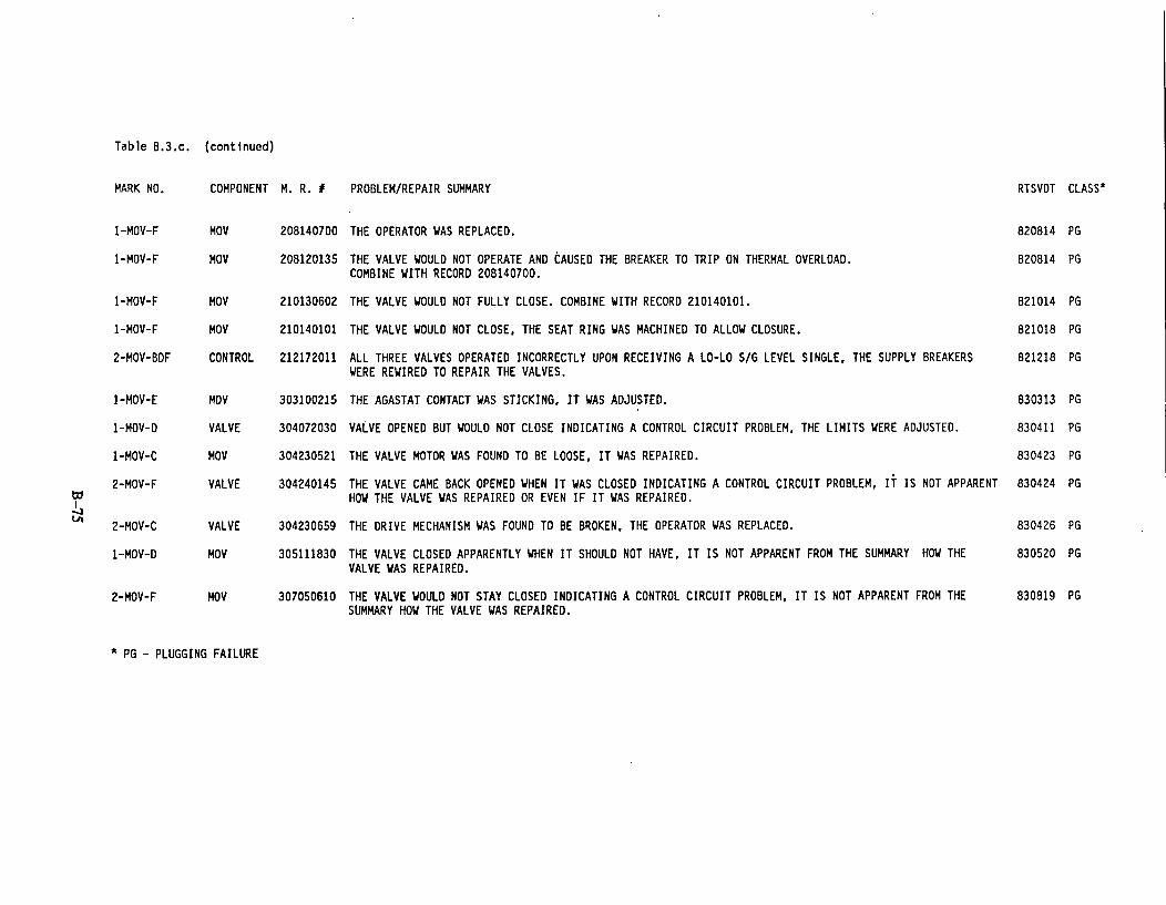
Table B.3.c. (continued)
MARK NO. COMPONENT M. R. # PROBLEM/REPAIR SUMMARY RTSVDT CLASS*
I-MOV-F MOV 208140700 THE OPERATOR WAS REPLACED. 820814 PG
1-MOV-F MOV 208120135 THE VALVE WOULD NOT OPERATE AND CAUSED THE BREAKER TO TRIP ON THERMAL OVERLOAD. 820814 PGCOMBINE WITH RECORD 208140700.
1-MOV-F MOV 210130602 THE VALVE WOULD NOT FULLY CLOSE. COMBINE WITH RECORD 210140101. 821014 PG
1-MOV-F MOV 210140101 THE VALVE WOULD NOT CLOSE, THE SEAT RING WAS MACHINED TO ALLOW CLOSURE. 821018 PG
2-MOV-BDF CONTROL 212172011 ALL THREE VALVES OPERATED INCORRECTLY UPON RECEIVING A LO-LO S/G LEVEL SINGLE, THE SUPPLY BREAKERS 821218 PGWERE REWIRED TO REPAIR THE VALVES.
1-MOV-E MOV 303100215 THE AGASTAT CONTACT WAS STICKING, IT WAS ADJUSTED. 830313 PG
1-MOV-D VALVE 304072030 VALVE OPENED BUT WOULD NOT CLOSE INDICATING A CONTROL CIRCUIT PROBLEM, THE LIMITS WERE ADJUSTED. 830411 PG
1-MOV-C MOV 304230521 THE VALVE MOTOR WAS FOUND TO BE LOOSE. IT WAS REPAIRED. 830423 PG
2-MOV-F VALVE 304240145 THE VALVE CAME BACK OPENED WHEN IT WAS CLOSED INDICATING A CONTROL CIRCUIT PROBLEM, IT IS NOT APPARENT 830424 PG5'd HOW THE VALVE WAS REPAIRED OR EVEN IF IT WAS REPAIRED.
2-MOV-C VALVE 304230659 THE DRIVE MECHANISM WAS FOUND TO BE BROKEN, THE OPERATOR WAS REPLACED. 830426 PG
1-MOV-D MOV 305111830 THE VALVE CLOSED APPARENTLY WHEN IT SHOULD NOT HAVE, IT IS NOT APPARENT FROM THE SUMMARY HOW THE 830520 PGVALVE WAS REPAIRED.
2-MOV-F MOV 307050610 THE VALVE WOULD NOT STAY CLOSED INDICATING A CONTROL CIRCUIT PROBLEM, IT IS NOT APPARENT FROM THE 830819 PGSUMMARY HOW THE VALVE WAS REPAIRED.
* PG - PLUGGING FAILURE

Table B.3.c. (continued)
MARK NO. COMPONENT M. R. # PROBLEM/REPAIR SUMMARY RTSVDT CLASS*
2-MOV-F VALVE 401131605 THE VALVE OPENED WHEN IT SHOULD NOT HAVE INDICATING A CONTROL CIRCUIT PROBLEM, THE AGASTAT WAS FOUND 840412 PGTO BE STICKING AND WAS REPAIRED.
1-MOV-D VALVE 406140300 LIMIT SWITCH GEAR WAS WORN AND WAS REPLACED, COMBINED WITH RECORD 406190408. 840614 PG
1-MOV-D VALVE 406191135 THE GEAR ASSEMBLY WAS REPLACED, COMBINED WITH RECORDS 406190408. 840620 PG
1-MOV-D VALVE 406190408 THE VALVE WOULD NOT CLOSE OR OPEN. THE LIMITS WERE REPLACED. 840620 PG
1-MOV-F MOV 13893 THE SUPPLY BREAKER TRIPPED, IT WAS CHECKED. 850213 PG
2-MOV-B MOV 02140 THE VALVE WAS REPAIRED DUE TO EXCESSIVE STROKE TIME. 850620 PG
2-MOV-D MOV 02382 THE VALVE WAS REPAIRED DUE TO EXCESSIVE STROKE TIME. 850620 PG
2-MOV-F MOV 02333 THE VALVE WAS REPAIRED DUE TO EXCESSIVE STROKE TIME. 850620 PG
1-MOV-D MOV 22962 THE SUPPLY BREAKER TRIPPED, IT WAS CHECKED. 850814 PG
2-MOV-A MOV 20540 COIL IN LATCHING RELAY FAILED, IT WAS REPLACED. 851029 PGW~4 1-MOV-0 MOV 29885 BREAKER TRIPPED ON THEMAL OVERLOAD, OVERLOADS RESET, NO FURTHER FAILURES. 860128 PG
1-MOV-D MOV 29920 VALVE MALFUNCTION, RECORD UNCLEAR. 860131 PG
2-MOV-D MOV 37688 VALVE DID NOT OPERATE BECAUSE AUXILIARY CONTACTS WERE STUCK, CONTACTS REPAIRED. 860715 PG
1-MOV-D MOV 45967 VALVE MALFUNCTION, RECORD UNCLEAR. 861123 PG
1-MOV-E MOV 29920 VALVE DID NOT OPEN DUE TO A STUCK INTERLOCK IN OPENING CIRCUIT. CONTACTOR REPLACED. 870219 PG
1-MOV-C MOV 46218 SPRING PACK HAD TO BE REPAIRED, APPARENTLY THE VALVE WOULD NOT WORK. 870225 PG
* PG - PLUGGING FAILURE

Table B.3.d. MAINTENANCE RECORDS BROADLY CLASSIFIED AS FAILURES FOR THE AUXILIARY FEEDWATER SYSTEM 6-INCH MOTOR OPERATED VALVES, REWRITTEN FORMAT
MARK NO. COMPONENT M. R. # PROBLEM/REPAIR SUMMARY RTSVDT CLASS*
2-MOV-J VALVE 810030726 THE VALVE WOULD NOT OPERATE, UNSPECIFIED REPAIRS WERE MADE AND THE VALVE WAS TESTED. 781006 FC
2-MOV-J MOV 812040631 THE SUPPLY BREAKER TRIPPED ON THERMAL OVERLOAD, THE VALVE WAS CLEANED AND THEN TESTED. 781204 FC
2-MOV-1 MOV 7231425 THE VALVE WAS BINDING UP, UNSPECIFIED REPAIRS WERE MADE. COMBINE WITH 8050929. 800801 FC
2-MOV-I MOV 8050929 THE LIMITORQUE OPERATOR WAS REPLACED OR REPAIRED. 800807 FC
2-MOV-J MOV 8122234 THE VALVE WOULD NOT COME FULLY OPEN. IT WAS CHECKED AND NO PROBLEMS WERE FOUND. 800814 FC
2-MOV-J VALVE 101131200 THE VALVE WAS BINDING AND WOULD NOT CLOSE, THE STEM THREADS WERE CLEANED. 810120 FC
1-MOV-G MOV 6120630 THE VALVE WOULD NOT OPEN, UNSPECIFIED REPAIRS WERE MADE. 810423 FC
1-MOV-G MOV 112120420 THE VALVE WOULD NOT CYCLE, THE LIMITS WERE ADJUSTED. 811212 FC
2-MOV-1 VALVE 304191635 THE MOTOR WAS DRAWING HIGH CURRENT DURING VALVE CYCLING, THE PACKING WAS ADJUSTED. 830423 FC
2-MOV-I VALVE 304231500 THE VALVE WOULD NOT OPEN, THE TORQUE SWITCH WAS CLEANED. COMBINE WITH 3014191635. 830423 FC
5 2-MOV-i VALVE 304191637 THE MOTOR WAS DRAWING HIGH CURRENT DURING VALVE CYCLING, THE PACKING WAS ADJUSTED. 830423 FC
2-MOV-J VALVE 304231427 THE VALVE WOULD NOT OPEN. THE TORQUE SWITCH WAS ADJUSTED. COMBINE WITH 3014191637. 830423 FC
1-MOV-G MOV 23350 REPIARED THE TORQUE SWITCH. 850823 FC
1-MOV-H MOV 30387 VALVE WOULD NOT STROKE, IT WAS CHECKED. 860211 FC
1-MOV-H MOV 39300 IT WAS NECESSARY TO REPLACE THE VALVE BEARINGS. 860807 FC
* FC - CROSS-CONNECTING FAILURE

Table B.3.e. MAINTENANCE RECORDS BROADLY CLASSIFIED AS FAILURES FOR THE AUXILIARY FEEDWATER SYSTEM 3-INCH CHECK VALVES, REWRITTEN FORMAT
MARK NO. COMPONENT M. R. # PROBLEM/REPAIR SUMMARY RTSVDT CLASS*
1-CV-J VALVE 4102000 THE WAS INSPECTED AND UNSPECIFIED REPAIRS WERE PERFORMED. 800415 LK
1-CV-H VALVE 4150916 THE WAS INSPECTED AND UNSPECIFIED REPAIRS WERE PERFORMED. 800417 LK
1-CV-I VALVE 4150915 THE WAS INSPECTED AND UNSPECIFIED-REPAIRS WERE PERFORMED. 800424 LK
1-CV-I VALVE 109210813 THE VALVE WAS OVERHAULED FOR SOME UNSPECIFIED REASON. 810930 LK
1-CV-H VALVE 109210811 THE VALVE WAS OVERHAULED FOR SOME UNSPECIFIED REASON. 810930 LK
1-CV-J VALVE 109210815 THE VALVE WAS OVERHAULED FOR SOME UNSPECIFIED REASON. 810930 LK
2-CV-H VALVE 110290942 THE VALVE WAS REPLACED FOR SOME UNSPECIFIED REASON. 811205 LK
2-CV-I VALVE 110290938 THE VALVE WAS REPLACED FOR SOME UNSPECIFIED REASON. IT HAD BEEN FURMANITED PREVIOUSLY. 811205 LK
2-CV-J VALVE 110290941 THE VALVE WAS REPLACED FOR SOME UNSPECIFIED REASON. 811215 LK
2-CV-H VALVE 312071039 THE CHECK VALVE SEAT WAS LEAKING, THE SEAT WAS REPAIRED. 831214 LK
2-CV-I VALVE 312071040 THE CHECK VALVE SEAT WAS LEAKING, THE SEAT WAS REPAIRED. 831221 LK00
2-CV-J VALVE 312071041 THE CHECK VALVE SEAT WAS LEAKING, THE SEAT WAS REPAIRED. 831221 LK
1-CV-H VALVE 312160902 THE CHECK VALVE SEAT WAS LEAKING, THE SEAT WAS REPAIRED. 840107 LK
2-CV-J VALVE 403131437 THE VALVE WAS INSPECTED FOR SOME REASON. IT WAS CUT OUT AND SENT TO CRANE FOR REPAIR. IT HAD BEEN 840406 LKFURMANITED SINCE IT WAS LAST REPLACED.
2-CV-I VALVE 403131441 THE VALVE WAS INSPECTED FOR SOME REASON, IT WAS CUT OUT AND SENT TO CRANE FOR REPAIR. 840406 LK
* LK - UNDETECTED LEAKAGE FAILURE
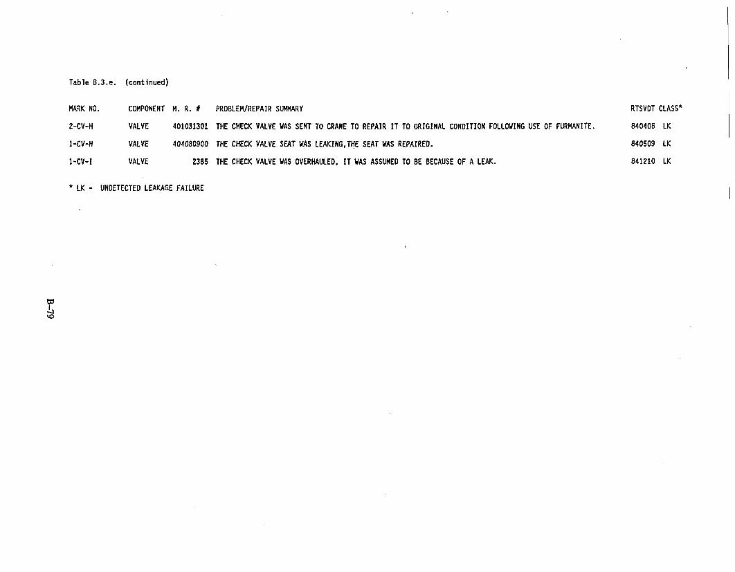
Table B.3.e. (continued)
MARK NO.
2-CV-H
1-CV-H
'-CV-'
COMPONENT
VALVE
VALVE
VALVE
M. R. # PROBLEM/REPAIR SUMMARY
401031301 THE CHECK VALVE WAS SENT TO CRANE TO REPAIR IT TO ORIGINAL CONDITION FOLLOWING USE OF FURMANITE.
404080900 THE CHECK VALVE SEAT WAS LEAKINGTHE SEAT WAS REPAIRED.
2385 THE CHECK VALVE WAS OVERHAULED. IT WAS ASSUMED TO BE BECAUSE OF A LEAK.
RTSVDT CLASS*
840406 LK
840509 LK
841210 LK
* LK - UNDETECTED LEAKAGE FAILURE
-4

Table B.3.f. MAINTENANCE RECORDS BROADLY CLASSIFIED AS FAILURES FOR THE AUXILIARY FEEDWATER SYSTEM 4-INCH CHECK VALVES, REWRITTEN FORMAT
MARK NO.
1-CV-C
1-CV-B
2-CV-C
2-CV-C
2-CV-C
2-CV-C
2-CV-C
2-CV-C
COMPONENT
VALVE
VALVE
VALVE
VALVE
VALVE
VALVE
VALVE
VALVE
M. R. #
304291402
304291400
305040509
311181137
311201310
401270925
403070933
1799
PROBLEM/REPAIR SUMMARY
THE CHECK VALVE SEAT WAS
THE CHECK VALVE SEAT WAS
THE CHECK VALVE SEAT WAS
THE CHECK VALVE SEAT WAS
THE CHECK VALVE SEAT WAS
THE CHECK VALVE SEAT WAS
THE CHECK VALVE SEAT WAS
THE CHECK VALVE SEAT WAS
LEAKING, THE SEAT WAS REPAIRED.
LEAKING, THE SEAT WAS REPAIRED.
LEAKING, THE SEAT WAS REPAIRED.
LEAKING, THE SEAT WAS INSPECTED.
LEAKING, THE SEAT WAS INSPECTED. COMBINE WITH 311181137.
LEAKING. THE SEAT WAS REPAIRED.
LEAKING, THE VALVE WAS CHECKED.
LAPPED. IT WAS ASSUMED TO HAVE BEEN LEAKING.
RTSVDT
830504
830525
830926
831119
831120
840128
840313
841218
CLASS*
LK/OO
LK/00
LK/OO
LK/O0
LK/OO
LK/OO
LK/OO
LK/OO
* LK - INCIPIENT UNDETECTED LEAKAGE FAILURE 00 - BACKFLOW FAILURE
000
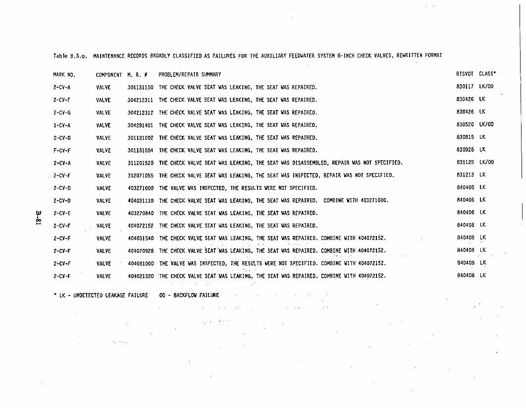
Table B.3.g. MAINTENANCE RECORDS BROADLY CLASSIFIED AS FAILURES FOR THE AUXILIARY FEEDWATER SYSTEM 6-INCH CHECK VALVES, REWRITTEN FORMAT
MARK NO. COMPONENT M. R. # PROBLEM/REPAIR SUMMARY RTSVDT CLASS*
2-CV-A VALVE 301131150 THE CHECK VALVE SEAT WAS LEAKING, THE SEAT WAS REPAIRED. 830117 LK/OO
2-CV-F VALVE 304212311 THE CHECK VALVE SEAT WAS LEAKING. THE SEAT WAS REPAIRED. 830426 LK
2-CV-G VALVE 304212312 THE CHECK VALVE SEAT WAS LEAKING, THE SEAT WAS REPAIRED. 830426 LK
1-CV-A VALVE 304291401 THE CHECK VALVE SEAT WAS LEAKING, THE SEAT WAS REPAIRED. 830520 LK/OO
2-CV-D VALVE 301131002 THE CHECK VALVE SEAT WAS LEAKING, THE SEAT WAS REPAIRED. 830815 LK
F-CV-F VALVE 301131004 THE CHECK VALVE SEAT WAS LEAKING, THE SEAT WAS REPAIRED. 830926 LK
2-CV-A VALVE 311201520 THE CHECK VALVE SEAT WAS LEAKING, THE SEAT WAS DISASSEMBLED, REPAIR WAS NOT SPECIFIED. 831129 LK/OO
2-CV-F VALVE 312071055 THE CHECK VALVE SEAT WAS LEAKING, THE SEAT WAS INSPECTED, REPAIR WAS NOT SPECIFIED. 831213 LK
2-CV-D VALVE 403271000 THE VALVE WAS INSPECTED, THE RESULTS WERE NOT SPECIFIED. 840406 LK
2-CV-D VALVE 404031130 THE CHECK VALVE SEAT WAS LEAKING, THE SEAT WAS REPAIRED. COMBINE WITH 403271000. 840406 LK
W 2-CV-E VALVE 403270840 THE CHECK VALVE SEAT WAS LEAKING, THE SEAT WAS REPAIRED. 840406 LK
Jo 2-CV-F VALVE 404072152 THE CHECK VALVE SEAT WAS-LEAKING, THE SEAT WAS REPAIRED. 840408 LK
2-CV-F VALVE 404031540 THE CHECK VALVE SEAT WAS LEAKING, THE SEAT WAS REPAIRED. COMBINE WITH 404072152. 840408 LK2-CV-F VALVE 404031540 THE CHECK VALVE SEAT WAS LEAK IING. THE SEAT WAS REPAIRED. COMBINE WITH 404072152. 840408 LK2-CV-F VALVE 404070928 THE CHECK VALVE SEAT'WAS LEAKING. THE SEAT WAS REPAIRED. COMBINE WITH 404072152. 840408 LK
2-CV-F VALVE 404081000 THE VALVE WAS INSPECTED, THE RESULTS WERE NOT SPECIFIED. COMBINE WITH 404072152. 840408 LK
2-CV-F VALVE 404021320 THE CHECK VALVE SEAT WAS LEAKING, THE SEAT WAS REPAIRED. COMBINE WITH 404072152. 840408 LK
* LK - UNDETECTED LEAKAGE FAILURE 00 - BACKFLOW FAILURE

Table B.3.g. (continued)
MARK NO. COMPONENT M. R. f PROBLEM/REPAIR SUMMARY RTSVDT CLASS*
2-CV-E VALVE 1222 THE CHECK VALVE SEAT WAS LEAKING. THE SEAT WAS REPAIRED. 841114 LK
2-CV-D VALVE 25924 THE CHECK VALVE SEAT WAS LEAKING. THE SEAT WAS REPAIRED. 861202 LK
2-CV-E VALVE 30558 IT WAS NECESSARY TO INSPECT AND REPAIR THE VALVE, IT IS ASSUMED THAT IT WAS LEAKING. 870104 LK
1-CV-A VALVE 49606 THE CHECK VALVE SEAT WAS LEAKING, THE SEAT WAS REPAIRED. 870214 LK/O0
1-CV-A VALVE 49048 THE CHECK VALVE SEAT WAS LEAKING. THE SEAT WAS REPAIRED. COMBINED WITH RECORD 49606. 870214 LK/OO
1-CV-A VALVE 53704 THE CHECK VALVE SEAT WAS LEAKING, THE SEAT WAS REPAIRED. 870528 1K/OO
* LK - UNDETECTED LEAKAGE FAILURE 00 - BACKFLOW FAILURE
w

Table B.4
Maintenance Records Narrowly Classifiedas Failures for the Auxiliary Feedwater System,
Rewritten Format
B-83 NUREG/CR-5378

Table B.4.a. MAINTENANCE RECORDS NARROWLY CLASSIFIED AS FAILURES FOR THE AUXILIARY FEEDWATER SYSTEM TURBINE DRIVEN FEED PUMPS, REWRITTEN FORMAT
MARK NO. COMPONENT M. R. # PROBLEM/REPAIR SUMMARY RTSVDT CLASS*
1-TDP PUMP 801010430 THE LUBRICATING OIL PRESSURE FAILED LOW RESULTING IN BEARING DAMAGE, REPLACED THRUST BEARING LINING. 780111 FR
2-TDP PUMP 11170730 DEFICIENCIES IN THE OVERSPEED TRIP VALVE CAUSED A PUMP TRIP, THE LINKAGE WAS STRAIGHTENED. 801118 FR
2-TDP PUMP 302111050 THE OVERSPEED TRIP CAUSED CAUSED INAPPROPRIATE PUMP TRIPS, THE OVERSPEED TRIP WAS CORRECTLY ADJUSTED. 830216 FR
2-TDP PUMP 303181232 FAILURE OF THE OVERSPEED TRIP SPRING TO STAY ENGAGED LED TO A PUMP TRIP, THE SPRING WAS REINSTALLED. 830321 FR
1-TOP PUMP 40487 THE GOVERNOR VALVE WOULD NOT OPEN, SPRING WAS REPLACED BUT THIS DID NOT HELP. 860907 FR
1-TDP PUMP 41325 GOVERNOR WAS REMOVED AND OVERHAULED BECAUSE POOR OPERATION. 860927 FR(THIS EVENT SHOULD WAS COMBINED WITH RECORD 40487)
1-TDP PUMP 40450 ADDITIONAL GOVERNOR WORK COMBINED WITH RECORD 40487. 860930 FR
1-TDP PUMP 40488 ADDITIONAL GOVERNOR WORK COMBINED WITH RECORD 40487. 860930 FR
1-TDP PUMP 40491 ADDITIONAL GOVERNOR WORK COMBINED WITH RECORD 40487. 860930 FR
* FR - FAILURE TO RUN FS - FAILURE TO START

Table 8.4.b.
MARK NO.
2-MOP-B
1-MOP-A
1-MDP-A
2-MDP-A
MAINTENANCE
COMPONENT
PUMP
PUMP
BREAKER
RELAY
RECORDS NARROWLY CLASSIFIED AS FAILURES FOR THE AUXILIARY FEEDWATER SYSTEM MOTOR DRIVEN PUMPS, REWRITTEN FORMAT
M. R. # PROBLEM/REPAIR SUMMARY
7222155 THE PUMP WOULD NOT START AUTOMATICALLY, IT WAS SOMEHOW REPAIRED.
203261300 THE PUMP FAILED BECAUSE THE BREAKER TRIPPED OPEN, BREAKER SHUT SATISFACTORILY AFTER REPAIR.IT WAS ASSUMED THAT THE BREAKER TRIPPED ON PUMP START.
306072125 A PHASE A RELAY DROPPED OUT, IT IS ASSUMED THAT THE PUMP TRIPPED SINCE A MEGGER WAS REQUIRED DURINGREPAIR.
310060105 A RELAY COIL FAILED IN THE START OR POWER CIRCUIT AND IT IS ASSUMED THAT THE PUMP FAILED TO START,THE RELAY WAS REPLACED.
RTSVDT CLASS*
800725 FS
820330 FS
830611 FS
831012 FS
* FR - FAILURE TO RUN FS - FAILURE TO START
ox

Table B.4.c. MAINTENANCE RECORDS NARROWLY CLASSIFIED AS FAILURES FOR THE AUXILIARY FEEDWATER SYSTEM 3-INCH MOTOR OPERATED VALVES, REWRITTEN FORMAT
MARK NO. COMPONENT M. R. # PROBLEM/REPAIR SUMMARY RTSVDT CLASS*
1-MOV-B MOV 806302330 THE SUPPLY BREAKER TRIPPED OPEN AND COULD NOT BE RESET, THE BREAKER WAS REPAIRED. 780706 PG
2-MOV-A MOV 810110135 THE VALVE DID NOT OPEN AUTOMATICALLY, THE CONTROL CIRCUIT WAS REPAIRED. 781015 PG
1-MOV-E MOV 1061910 THE MOTOR HOUSING FOR THE VALVE SHATTERED AND HAD TO BE REPLACED, IT WAS REPLACED WITH 251E MOTOR. 800107 PG1-MOV-E MOV 1061825 POWER WAS DISCONNECTED AND RECONNECTED TO FACILITATE MOTOR REPLACEMENT. COMBINE WITH 1061910. 800219 PG
2-MOV-E MOV 1062046 THE MOTOR (AND MAYBE THE VALVE?) WAS REMOVED FOR USE ON UNIT 1. COMBINE WITH 106190. 800323 PG2-MOV-F VALVE 4291230 THE MOTOR WAS DISASSEMBLED FOR INSPECTION AND FOUND TO BE STUCK, IT WAS REPAIRED. 800509 PG2-MOV-D MOV 5281601 THE SUPPLY BREAKER TRIPPED OPEN APPARENTLY ON OVERLOAD, A (TORQUE?) SWITCH WAS ADJUSTED TO FIX THE MOV. 800602 PG2-MOV-B MOV 11011730 THE MOV WOULD NOT OPERATE AND BAD LEADS WERE FOUND, THE LEADS WERE REPAIRED. 801104 PG1-MOV-F MOV 110011750 THE MOV INDICATED CLOSED LOCALLY, THE VALVE WAS FOUND NOT TO OPERATE SATISFACTORILY. 811001 PG1-MOV-F MOV 208140700 THE OPERATOR WAS REPLACED. 820814 PG1-MOV-F MOV 208120135 THE VALVE WOULD NOT OPERATE AND CAUSED THE BREAKER TO TRIP ON THERMAL OVERLOAD. 820814 PGCOMBINE WITH RECORD 208140700.
2-MOV-C VALVE 304230659 THE DRIVE MECHANISM WAS FOUND TO BE BROKEN, THE OPERATOR WAS REPLACED. 830426 PG1-MOV-D MOV 305111830 THE VALVE CLOSED APPARENTLY WHEN IT SHOULD NOT HAVE, IT IS NOT APPARENT FROM THE SUMMARY HOW THE 830520 PGVALVE WAS REPAIRED.
* PG - PLUGGING FAILURE

Table B.4.c. (continued)
MARK NO. COMPONENT M. R. # PROBLEM/REPAIR SUMMARY RTSVDT CLASS*1-MOV-D VALVE 406140300 LIMIT SWITCH GEAR WAS WORN AND WAS REPLACED, COMBINED WITH RECORD 406190408. 840614 PG1-MOV-D VALVE 406191135 THE GEAR ASSEMBLY WAS REPLACED, COMBINED WITH RECORDS 406190408. 840620 PG1-MOV-D VALVE 406190408 THE VALVE WOULD NOT CLOSE OR OPEN, THE LIMITS WERE REPLACED. 840620 PG1-MOV-D MOV 13893 THE SUPPLY BREAKER TRIPPED, IT WAS CHECKED. 850213 PG1-MOV-D MOV 22962 THE SUPPLY BREAKER TRIPPED, IT WAS CHECKED. 850814 PG2-MOV-A MOV 20540 COIL IN LATCHING RELAY FAILED, IT WAS REPLACED. 851029 PG1-MOV-D MOV 29885 BREAKER TRIPPED ON THEMAL OVERLOAD, OVERLOADS RESET, NO FURTHER FAILURES. 860128 PG2-MOV-D MOV 37688 VALVE DID NOT OPERATE BECAUSE AUXILIARY CONTACTS WERE STUCK, CONTACTS REPAIRED. 860715 PG1-MOV-E MOV 29920 VALVE DID NOT OPEN DUE TO A STUCK INTERLOCK IN OPENING CIRCUIT. CONTACTOR REPLACED. 870219 PG
* PG - PLUGGING FAILUREtz0000

Table B.4.d MAINTENANCE RECORDS NARROWLY CLASSIFIED AS FAILURES FOR THE AUXILIARY FEEDWATER SYSTEM 6-INCH MOTOR OPERATED VALVES, REWRITTEN FORMAT
MARK NO. COMPONENT M. R. I PROBLEM/REPAIR SUMMARY RTSVDT CLASS*
2-MOV-J VALVE 810030726 THE VALVE WOULD NOT OPERATE, UNSPECIFIED REPAIRS WERE MADE AND THE VALVE WAS TESTED. 781006 FC
2-MOV-J MOV 812040631 THE SUPPLY BREAKER TRIPPED ON THERMAL OVERLOAD. THE VALVE WAS CLEANED AND THEN TESTED. 781204 FC
2-MOV-1 MOV 7231425 THE VALVE WAS BINDING UP, UNSPECIFIED REPAIRS WERE MADE. COMBINE WITH 8050929. 800801 FC
2-MOV-1 MOV 8050929 THE LIMITORQUE OPERATOR WAS REPLACED OR REPAIRED. 800807 FC
2-MOV-J VALVE 101131200 THE VALVE WAS BINDING AND WOULD NOT CLOSE, THE STEM THREADS WERE CLEANED. 810120 FC
1-MOV-G NOV 112120420 THE VALVE WOULD NOT CYCLE, THE LIMITS WERE ADJUSTED. 811212 FC
1-MOV-H MOV 30387 VALVE WOULD NOT STROKE. IT WAS CHECKED. 860211 FC
* FC - CROSS-CONNECTING FAILURE

Table B.4.e. MAINTENANCE RECORDS NARROWLY CLASSIFIED AS FAILURES FOR THE AUXILIARY FEEDWATER SYSTEM 3-INCH CHECK VALVES, REWRITTEN FORMAT
MARK NO.
2-CV-H
2-CV-I
2-CV-J
1-CV-H
COMPONENT
VALVE
VALVE
VALVE
VALVE
M. R. I PROBLEM/REPAIR SUMMARY
312071039 THE CHECK VALVE SEAT WAS LEAKING, THE SEAT WAS REPAIRED.
312071040 THE CHECK VALVE SEAT WAS LEAKING, THE SEAT WAS REPAIRED.
312071041 THE CHECK VALVE SEAT WAS LEAKING, THE SEAT WAS REPAIRED.
312160902 THE CHECK VALVE SEAT WAS LEAKING, THE SEAT WAS REPAIRED.
RTSVDT CLASS*
831214 LK
831221 LK
831221 LK
840107 LK
* LK - UNDETECTED LEAKAGE FAILURE
w
0

Table B.4.f. MAINTENANCE RECORDS NARROWLY CLASSIFIED AS FAILURES FOR THE AUXILIARY FEEDWATER SYSTEM 4-INCH CHECK VALVES, REWRITTEN FORMAT
MARK NO. COMPONENT M. R. I PROBLEM/REPAIR SUMMARY RTSVDT CLASS*
1-CV-C VALVE 304291402 THE CHECK VALVE SEAT WAS LEAKING, THE SEAT WAS REPAIRED. 830504 LK
1-CV-B VALVE 304291400 THE CHECK VALVE SEAT WAS LEAKING, THE SEAT WAS REPAIRED. 830525 LK
2-CV-C VALVE 305040509 THE CHECK VALVE SEAT WAS LEAKING, THE SEAT WAS REPAIRED. 830926 LK
2-CV-C VALVE 311181137 THE CHECK VALVE SEAT WAS LEAKING, THE SEAT WAS INSPECTED. 831119 LK
2-CV-C VALVE 311201310 THE CHECK VALVE SEAT WAS LEAKING, THE SEAT WAS INSPECTED. COMBINE WITH 311181137. 831120 LK
2-CV-C VALVE 401270925 THE CHECK VALVE SEAT WAS LEAKING, THE SEAT WAS REPAIRED. 840128 LK
2-CV-C VALVE 403070933 THE CHECK VALVE SEAT WAS LEAKING, THE VALVE WAS CHECKED. 840313 LK
* LK - INCIPIENT UNDETECTED LEAKAGE FAILURE

Table B.4.g. MAINTENANCE RECORDS NARROWLY CLASSIFIED AS FAILURES FOR THE AUXILIARY FEEDWATER SYSTEM 6-INCH CHECK VALVES, REWRITTEN FORMAT
MARK NO. COMPONENT M. R. # PROBLEM/REPAIR SUMMARY RTSVDT CLASS*
2-CV-A VALVE 301131150 THE CHECK VALVE SEAT WAS LEAKING, THE SEAT WAS REPAIRED. 830117 LK
2-CV-F VALVE 304212311 THE CHECK VALVE SEAT WAS LEAKING, THE SEAT WAS REPAIRED. 830426 LK
2-CV-G VALVE 304212312 THE CHECK VALVE SEAT WAS LEAKING, THE SEAT WAS REPAIRED. 830426 LK
1-CV-A VALVE 304291401 THE CHECK VALVE SEAT WAS LEAKING, THE SEAT WAS REPAIRED. 830520 LK
2-CV-D VALVE 301131002 THE CHECK VALVE SEAT WAS LEAKING. THE SEAT WAS REPAIRED. 830815 LK
2-CV-F VALVE 301131004 THE CHECK VALVE SEAT WAS LEAKING, THE SEAT WAS REPAIRED. 830926 LK
2-CV-A VALVE 311201520 THE CHECK VALVE SEAT WAS LEAKING, THE SEAT WAS DISASSEMBLED, REPAIR WAS NOT SPECIFIED. 831129 LK
2-CV-F VALVE 312071055 THE CHECK VALVE SEAT WAS LEAKING, THE SEAT WAS INSPECTED, REPAIR WAS NOT SPECIFIED. 831213 LK
2-CV-D VALVE 404031130 THE CHECK VALVE SEAT WAS LEAKING, THE SEAT WAS REPAIRED. COMBINE WITH 403271000. 840406 LK
2-CV-E VALVE 403270840 THE CHECK VALVE SEAT WAS LEAKING, THE SEAT WAS REPAIRED. 840406 LK
to 2-CV-F VALVE 404072152 THE CHECK VALVE SEAT WAS LEAKING, THE SEAT WAS REPAIRED. 840408 LK
2-CV-F VALVE 404031540 THE CHECK VALVE SEAT WAS LEAKING, THE SEAT WAS REPAIRED. COMBINE WITH 404072152. 840408 LK
2-CV-F VALVE 404070928 THE CHECK VALVE SEAT WAS LEAKING, THE SEAT WAS REPAIRED. COMBINE WITH 404072152. 840408 LK
2-CV-F VALVE 404021320 THE CHECK VALVE SEAT WAS LEAKING, THE SEAT WAS REPAIRED. COMBINE WITH 404072152. 840408 LK
2-CV-E VALVE 1222 THE CHECK VALVE SEAT WAS LEAKING, THE SEAT WAS REPAIRED. 841114 LK
2-CV-D VALVE 25924 THE CHECK VALVE SEAT WAS LEAKING, THE SEAT WAS REPAIRED. 861202 LK
1-CV-A VALVE 49606 THE CHECK VALVE SEAT WAS LEAKING, THE SEAT WAS REPAIRED. 870214 LK
1-CV-A VALVE 49048 THE CHECK VALVE SEAT WAS LEAKING, THE SEAT WAS REPAIRED. COMBINED WITH RECORD 49606. 870214 LK
1-CV-A VALVE 53704 THE CHECK VALVE SEAT WAS LEAKING, THE SEAT WAS REPAIRED. 870528 LK
* LK - UNDETECTED LEAKAGE FAILURE.

NRC FORM 335 U.S. NUCLEAR REGULATORY COMMISSION 1. REPORT NUMBER12-89) 4IAa.Ignd by NRC. Add Vol., Spp.. R._NRCM 1102. ed Addendum Numbes, If mny.)3201,3202 BIBLIOGRAPHIC DATA SHEET
(See instructions on the reverse) NUREG CR6 53782. TITLE AND SUBTITLE-2567
Aging Data Analysis and Risk Assessment--Development 3. DATE REPORT PUBLISHED
and Demonstration Study MONTH i YEAR
August 19924. FIN OR GRANT NUMBER
A63895. AUTHORIS) 6. TYPE OF REPORT
A. J. Wolford*, C. L. Atwood, W. S. Roesener Technical
7. PERIOD COVERED Itnclusive Dares)
B. PE RFO RM ING ORGAN IZATION -NAM E AND ADD RESS (If NRC.prrwide Divisio~n, Office Or ®ion, U.S.Nucb e Regu/arory Co-.isio and mailingaddress if ontroctof, providenate and mailing address I
Idaho National Engineering Laboratory *DNV TechnicaEG&G Idaho, Inc. 355 East Campus View Blvd.Idaho Falls, ID 83415 Suite 710
Columbus, OH 43235
9. SPONSOR ING ORGAN IZATI ON -NAME AND ADDR ESSl WNRC, type S~ax sJ bove-; icontrrctofprovide NRC Division, Office or fegio~n, U.1 Nuclear Regulatory Commission,and mailing address.)
Division of EngineeringOffice of Nuclear Regulatory ResearchU.S. Nuclear Regulatory CommissionWashington, DC 20555
10. SUPPLEMENTARY NOTES
11. ABSTRACT 200 words or kae
This work develops and demonstrates a probabilistic risk assessment (PRA) approach to assess the effect of agingand degradation of active components on plant risk. The work (a) develops a way to identify and quantify age-depen-dent failure rates of active components, and to incorporate them into PRA; (b) demonstrates the approach by applyingit to a fluid-mechanical system, using the key elements of a NUREG-1 150 PRA; and (c) presents it as a step-by-stepapproach, to be used for evaluating the risk significance of aging phenomena in systems of interest.
The approach uses statistical tests to detect increasing failure rates and for testing data-pooling assumptions and modeladequacy. The component failure rates are assumed to change over time, with several forms used to model the agedependence-exponential, Weibull, and linear. Confidence intervals for the age-dependent failure rates are found andused to develop inputs to a PRA model in order to determine the plant core damage frequency. The approach was usedwith plant-specific data, obtained from maintenance work requests for the auxiliary feedwater system of an older pressur-ized water reactor. The approach can be used for extrapolating present trends into the near future and for supporting risk-based aging management decisions.
12. KEY WORDS/DESCR!PTORS (List words orpihrases that willassist researchers in locating the report.) 13. AVAILABILITY STATEMENT
Management of Aging ~~~~~~~~~UnlimitedManagement of Aging 14. SECURITY CLASSIFICATION
Probabilistic Risk Assessment (This PageI
Unclassified(This Report)
Unclassified15. NUMBER OF PAGES
16. PRICE
NRC FORM 335 12891

THIS DOCUMENT WAS PRINTED USING RECYCLED PAPER

NUCLEAR REGULATORY COMMISSIONWASHINGTON, D.C. 20555-0001
OFFICIAL BUSINESSPENALTY FOR PRIVATE USE, $300
. _ _ _ _
( _ _ ,_ ,_ _._...__ .. .. .. ..
POSTAGE AND FEES PAIDUSNRC
PERMIT NO. G-67