nureg/cr-6421, 'a proposed acceptance process for commercial
TRANSCRIPT

NUREG/CR-6421UCRL-ID-122526
A Proposed AcceptanceProcess forCommercial Off-the-Shelf (COTS)Software in Reactor Applications
Prepared byG. G. Preckshot, J. A. Scott
Lawrence Livermore National Laboratory
Prepared forU.S. Nuclear Regulatory Commission

AVAILABILITY NOTICE
Availability of Reference Materials Cited in NRC Publications
Most documents cited In NRC publications will be available from one of the following sources:
1. The NRC Public Document Room, 2120 L Street, NW., Lower Level. Washington, DC 20555-0001
2. The Superintendent of Documents, U.S. Government Printing Office, P. 0. Box 37082, Washington, DC
20402-9328
3. The National Technical Information Service, Springfield, VA 22161-0002
Although the listing that follows represents the majority of documents cited in NRC publications, it is not in-tended to be exhaustive.
Referenced documents available for Inspection and copying for a fee from the NRC Public Document Roominclude NRC correspondence and internal NRC memoranda; NRC bulletins, circulars, information notices, in-spection and investigation notices; licensee event reports; vendor reports and correspondence; Commissionpapers; and applicant and licensee documents and correspondence.
The following documents In the NUREG series are available for purchase from the Government Printing Office:formal NRC staff and contractor reports, NRC-sponsored conference proceedings, international agreementreports, grantee reports, and NRC booklets and brochures. Also available are regulatory guides, NRC regula-tions In the Code of Federal Regulations, and Nuclear Regulatory Commission Issuances.
Documents available from the National Technical Information Service Include NUREG-series reports and tech-nical reports prepared by other Federal agencies and reports prepared by the Atomic Energy Commission,forerunner agency to the Nuclear Regulatory Commission.
Documents available from public and special technical libraries include all open literature items, such as books.journal articles, and transactions. Federal Register notices. Federal and State legislation, and congressionalreports can usually be obtained from these libraries.
Documents such as theses, dissertations, foreign reports and translations, and non-NRC conference pro-ceedings are available for purchase from the organization sponsoring the publication cited.
Single copies of NRC draft reports are available free. to the extent of supply, upon written request to the Officeof Administration, Distribution and Mail Services Section, U.S. Nuclear Regulatory Commission, Washington,DC 20555-0001.
Copies of Industry codes and standards used in a substantive manner in the NRC regulatory process are main-tained at the NRC Library, Two White Flint North. 11545 Rockville Pike, Rockville, MD 20852-2738. for use bythe public. Codes and standards are usually copyrighted and may be purchased from the originating organiza-tion or, if they are American National Standards, from the American National Standards Institute, 1430 Broad-way, New York, NY 10018-3308.
DISCLAIMER NOTICE
This report was prepared as an account of work sponsored by an agency of the United States Government.Neitherthe United States Government norany agencythereof, norany of theiremployees, makes any warranty,expressed or implied, or assumes any legal liability or responsibility for any third party's use, or the results ofsuch use, of any information, apparatus, product, or process disclosed in this report, or represents that its useby such third party would not infringe privately owned rights.
NUREG/CR-6421UCRL-ID-122526
A Proposed AcceptanceProcess forCommercial Off-the-Shelf (COTS)Software in Reactor Applications
Manuscript Completed: September 1995Date Published: March 1996
Prepared byG. G. Preckshot, J. A. Scott
Lawrence Livermore National LaboratoryLivermore, CA 94551
I. Gallagher, NRC Technical Monitor
Prepared forDivision of Reactor Controls and Human FactorsOffice of Nuclear Reactor RegulationU.S. Nuclear Regulatory CommissionWashington, DC 20555-0001NRC Job Code L1857


ABSTRACTThis paper proposes a process for acceptance of commercial off-the-shelf (COTS) software products for use inreactor systems important to safety. An initial set of four criteria establishes COTS software product identificationand its safety category. Based on safety category, three sets of additional criteria, graded in rigor, are applied toapprove (or disapprove) the product. These criteria fall roughly into three areas: product assurance, verification ofsafety function and safety impact, and examination of usage experience of the COTS product in circumstancessimilar to the proposed application. A report addressing the testing of existing software is included as an appendix.
i°i NUREG/CR-6421


CONTENTS
A cknow ledgm ent ......................................................................................................................................................... vii
Executive Sum m ary ...................................................................................................................................................... ix
1.0 Introduction ............................................................................................................................................................. 11.1 Scope ....................................................................................................................... ......................................... 11.2 Purpose ............................................................................................................................................................. 11.3 D efinitions ........................................................................................................................................................ 11.4 Backgrounnd ................................................................................................................. I ..................................... 2
1.4.1 CO TS Background and Feasibility ................................................................................. .............. . 21.4.1.1 Commercial-Off-the-Shelf Software and its Acceptability ................................................ 21.4.1.2 Feasibility Issues ...................................................................................................................... 31.4.1.3 Perspectives on A cceptability Evaluations ......................................................................... 3
1.4.2 Background on the Proposed Acceptance Process .......................................................................... 51.4.2.1 Classification ................. I .......................................................................................................... 51.4.2.2 Basis for the A cceptance Criteria ....................................................................................... 51.4.2.3 Acceptance Process, Criteria, and Conclusions .................................................................. 6
2.0 Safety Categories ..................................................................................................................................................... 72.1 IEC 1226 Categories ........................................................................................................................................ 72.2 CO TS U sage Categories ........................................ I ......................................................................................... 72.3 Special Note on Compilers, Linkers, and Operating Systems .................................................................... 7
3.0 O verview of Standards Review ed ........................................................................................................................... 93.1 IEEE 730 (N ow 730.1) ..................................................................................................................................... 93.2 IEEE 983 (P730.2, D raft 5) ............................................................................................................................. 93.3 IEEE 828 .......................................................................................................................................................... 93.4 IEEE 1042 ........................................................................................................................................................ 93.5 IS0 9000-3 ...................................................................................................................................................... 93.6 A N SI/AN S-10.4 ............................................................................................................................................... 93.7 AN SIIIEEE 1012 ........................................................................................................................................... 103.8 IEC 880 .......................................................................................................................................................... 103.9 IEC 987 .......................................................................................................................................................... 103.10 IEC 880, First Supplem ent to IEC 880 (Draft) ...................................................................................... 103.11 IEEE-74 .3.2-1993 ....................................................................................................................................... 103.12 IEC 1226 ...................................................................................................................................................... 11
4.0 Proposed A cceptance Process ............................................................................................................................... 134.1 Commercial-Grade Dedication for Class-of-Service ............................................................................... 134.2 Preliminary Phase of the Proposed Acceptance Process ............................................................................ 14
4.2.1 Acceptance Criterion 1-Risk and Hazards Analyses .................................................................. 14
4.2.2 Acceptance Criterion 2-Identification of Safety Functions ........................................................ 144.2.3 Acceptance Criterion 3--Configuration Management ................................................................ 144.2.4 Acceptance Criterion 4-Determination of Safety Category ..................................................... 15
4.3 D etailed A cceptance Criteria for Category A ........................................................................................... 154.3.1 Acceptance Criterion A5-Product Assurance ............................................................................ 154.3.2 Acceptance Criterion A6-Product Documentation ..................................................................... 164.3.3 Acceptance Criterion A7-Product Safety Requirements ........................................................... 164.3.4 A cceptance Criterion A -- System Safety ................................................................ .......... 164.3.5 Acceptance Criterion A9-Interface Requirements .................................... 174.3.6 A cceptance Criterion A 10- Experience D atabase ............................................................................ 17
v NNUREG/CR-6421

4.3.7 Acceptance Criterion A .1- Error Reporting Requirem ent .......................................................... 174.3.8 Acceptance Criterion A12-Additional V&V Requirement ........................................................ 17
4.4 Detailed Acceptance Criteria for Category B ................................................ ............................................ 174.4.1 Acceptance Criterion B5W - Product Assurance ............................................................................ 174.4.2 Acceptance Criterion B6- Product Documentation .................................................................... 174.4.3 Acceptance Criterion B7- Product Safety Requirements ............................................................ 174.4.4 Acceptance Criterion B --System Safety ................................................................................... 184.4.5 Acceptance Criterion B9- Experience Database ......................................................................... 184.4.6 Acceptance Criterion B 10- Error Reporting Requirement .......................................................... 18
4.5 Detailed Acceptance Criteria for Category C .......................................................................................... 184.5.1 Acceptance Criterion C5- Product Assurance .................................................................................. 184.5.2 Acceptance Criterion C6- Product Documentation .................................................................... 184.5.3 Acceptance Criterion C7-Product Safety Requirements ........................... 184.5.4 Acceptance Criterion C8- System Safety ................................................................................... 194.5.5 Acceptance Criterion C9- Experience Database ......................................................................... 194.5.6 Acceptance Criterion C10-Error Reporting Requirement .......................................................... 19
5.0 Conclusions ........................................................................................................................................................... 21
References .................................................................................................................................................................... 23
Appendix A- Preliminary List of Factors ............................................................................................................ 25
Appendix B-Testing Existing Software for Safety-Related Applications .......................................................... 35
TABLES
Table 1. Safety Categories ............................................................................................................................................ 8Table 2. COTS Usage Categories ................................................................................................................................. 8Table 3. COTS Safety Category Criteria ....................................................................................................................... 8Table 4. Preliminary COTS Acceptance Criteria ................................................................................................... 13Table 5. Category A COTS Acceptance Criteria .................................................................................................. 15Table 6. Category B COTS Acceptance Criteria .................................................................................................. 18Table 7. Category C COTS Acceptance Criteria .................................................................................................. 19Table A-1. Failure Consequence Criteria ................................................................................................... ..... 25Table A-2. Plan Existence Criteria .............................................................................................................................. 25Table A-3. SQA Criteria ............................................................................................................................................. 26Table A-4. Software Configuration M anagement Criteria ................................................................................... 27Table A-5. Software V&V Criteria .............................................................................................................................. 28Table A-6. Actions to Take W hen Data is M issing ............................................................................................... 29Table A-7. M inimum SQA Docum entation .......................................................................................................... 29
Table A-8. M inimum Required SQA Reviews and Audits ................................................................................... 29
Table A-9. SQA, SCM, and V&V for Other Software Suppliers ................................ 30
Table A-10. Suggested Additional Docum entation ............................................................................................... 30Table A-11. Suggested Areas of Standardization .................................................................................................. 30Table A-12. M inim um V&V Tasks ............................................................................................................................ 31Table A-13. M inim um Docum entation Needed for a Posteriori V&V .................................................................. 32Table A-14. Typical Policies and Directives of a Configuration Management Operation .................................... 33
NUREG/CR-6421 vi

ACKNOWLEDGMENT
The authors thank and acknowledge the efforts of Nuclear Regulatory Commission staff members, Leo Beltracchi,Robert Brill, John Gallagher, Joe Joyce, Joel Kramer, and James Stewart, who reviewed this work and provided theirinsights and comments.
vii NUREG/CR-6421

EXECUTIVE SUMMARY
The approval process for commercial off-the-shelf (COTS) software to be used in reactor safety systems (Class IE)has been termed "commercial dedication," although this term also implies defect reporting responsibilities (for thededicator) under 10 CFR 21. Since this document addresses only the investigation of the acceptability of suchsoftware for use in systems important to safety, the term "acceptance process" is used. The purpose of this work is toreview current and draft standards to create a set of "acceptance criteria" and incorporate them into a proposedacceptance process. The resulting acceptance criteria are assessed with regard to NRC practices and regulatorypurview to arrive at an ordered set of criteria related to safety that comprises a proposed process for accepting COTSsoftware for use in reactor safety applications. Prior to discussing the acceptance process, summary information isprovided regarding the nature of the problem of acceptance and the feasibility of using COTS software in reactorsafety applications. The latter describes some cost-related considerations, other than purchase price, that areassociated with using COTS software in systems important to safety.
In keeping with NRC practices, wherein reactor equipment is regulated primarily in proportion to its importance toreactor safety, it is proposed that COTS products should be reviewed with a stringency proportional to the safetyfunctions they are intended to provide. An initial set of four criteria, comprising the preliminary phase of theacceptance process, establishes COTS product identification and its safety category. Based on safety category, oneof three sets of additional criteria, graded in rigor, is applied to approve (or disapprove) the product. These criteriafall roughly into three areas: product assurance, verification of safety function and safety impact, and examination ofusage experience of the COTS product in circumstances similar to the proposed application.
Several conclusions are drawn. First, it is feasible to design an acceptance process based on a classification ofsoftware with respect to its importance to safety. Second, the rank order of acceptance criteria is dictated by datadependencies. The exercise of satisfying first-ranked criteria produces data that are necessary for the remainingcriteria. Thus, no basis for satisfying subsequent criteria exists if "upstream" criteria are not satisfied. Finally, nosingle standard extant at this writing completely addresses the acceptance problem. Taken in combination, however,a usable set of criteria for determining the acceptability of a COTS software item can be derived from IEC, IEEE,and ISO standards. Based on the results, it appears that acceptable COTS software items can be produced by vendorswho are generally aware of the risks associated with systems important to safety and who employ accepted softwareengineering practice to produce high-integrity software.
ix NUREG/CR-6421


Section 1. Introduction
A PROPOSED ACCEPTANCE PROCESSFOR COMMERCIAL OFF-THE-SHELF (COTS)
SOFTWARE IN REACTOR APPLICATIONS
1.0 INTRODUCTION
1.1 Scope
This report addresses the use of commercial off-the-shelf (COTS) software in those nuclear power plant(NPP) systems that have some relationship to safety.The report proposes a process for determining theacceptability of COTS software using a classificationscheme based on the importance to safety of the systemin which the COTS product will be used. Sincesoftware testing is related to the acceptance process,the report, Testing Existing Software for Safety-RelatedApplications, has been included as Appendix B of thisreport.
1.2 Purpose
The purpose of this report is to present a proposedacceptance process, based on a review of current anddraft standards, for the use of COTS software items inNPP systems important to safety. The process iscentered on suitable "acceptance criteria" that aresupported by inclusion in a majority of standardspublications or work-in-progress and that areconsistent with NRC practices and regulatory purview.
1.3 Definitions
Key terms used in the report are defined below.
Class 1E
The safety classification of the electric equipment andsystems that are essential to emergency reactorshutdown, containment isolation, reactor core cooling,and containment and reactor heat removal, or areotherwise essential in preventing significant release ofradioactive material to the environment.
Commercial-grade dedication
An acceptance process undertaken to providereasonable assurance that a commercial-grade item tobe used as a basic component will perform its intendedsafety function and, in this respect, will be deemedequivalent to an item designed and manufactured undera 10 CFR Part 50, Appendix B, quality assuranceprogram.2
Critical software
Software that is part of, or could affect, the safetyfunction of a basic component or a commercial-gradesoftware item that undergoes commercial-gradededication.
Important to safety
A structure, system, or component:
a whose failure could lead to a significant radiationhazard,
b. that prevents anticipated operational occurrencesfrom leading to accident conditions, or
c. that is provided to mitigate consequences of failureof other structures, systems or components.
This encompasses both safety and safety-relatedsystems.
Safety-related
Pertaining to systems important to safety but that arenot safety systems.
Safety systems
Commercial-grade item
A structure, system, or component, or part thereof thatis used in the design of a nuclear power plant andwhich could affect the safety function of the plant, butwas not designed and manufactured as a basiccomponent. I
I This definition is sufficient for this report; see 10 CFR Part 21 (inthe revision process as of this writing) for the complete currentdefinition.
Those systems that are relied upon to remain functionalduring and following design basis events to ensure (a)the integrity of the reactor coolant pressure boundary,(b) the capability to shut down the reactor and maintainit in a safe shutdown condition, or (c) the capability toprevent or mitigate the consequences of accidents that
2Since this report is concerned with the specifics of gainingreasonable assurance, and not with the aspects of 10 CFR that willapply following the actual acceptance of a commercial-grade itmn,the process of gaining assurance is called an "acceptance process"rather than a 'commercial dedication process."
1 SNUREG/CR-6421
Section 1. Introduction
could result in potential offsite exposures comparableto the 10 CFR Part 100 guidelines.
Statistical certainty
An assertion made within calculated confidence limitssupported by data samples and an underlyingdistribution theory.
Statistical validity
An assertion is statistically valid if the attributes of thedata supporting the statistical certainty of the assertionare consistent with the inference to be made.
(The term, statistical validity, is used in several placesin this report to refer to operating experience of acommercial-grade software item. The connotations ofthis usage are:
" for each datum in the operating experiencedatabase, the version and release numbers of theinvolved software item are identified and match thetarget commercial-grade software item; and,
* for each datum, the operating environment,configuration, and usage are reported and match theintended environment, configuration, and usage ofthe target commercial-grade software item; and,
" all received reports and incident details are recordedin the database, regardless of initial diagnosis; and,
* an estimate3 is made of the expected number ofunreported, unique incidents, 4 with confidencelimits; and,
" the number of reports in the database, theconfidence interval, and the expected number ofunreported severe errors are consistent with theintended use of the commercial-grade softwareitem.)
1.4 Background
Considerable interest exists in the nuclear powercommunity in the potential use of commercial off-the-shelf software in nuclear power plant systems. Forsafety-related systems, it is necessary to evaluate theacceptability of the COTS software for use in thesystem and then to formally designate the COTSsoftware as a "basic component" of a system essentialto reactor safety. This is referred to as "dedication of acommercial-grade item" by 10 CFR Part 21, althoughthe term "commercial dedication" was sometimes alsoused to signify only the formal acceptance of the
3An estimate can be made from the frequency distribution of reportsof unique incidents, or direct sampling of the software user datasource4 A unique incident is one that, after root-cause analysis, has adifferent root cause from all previously reported incidents.
product and assumption of 10 CFR 21 defect-reportingresponsibilities. Since this report addresses only theevaluation and acceptance of COTS software in bothsafety-related systems and in other systems importantto safety, the process is referred to herein as an"acceptance process."
The acceptance process used to determine theacceptability of a COTS software item is currently thesubject of much debate. This section of the reportdiscusses key issues related to the feasibility of usingCOTS software in systems important to safety, a briefdiscussion of the varying perspectives of typicalparticipants, and background information regarding thedevelopment of the proposed acceptance process. Thefollowing sections of this report address theclassification of software to be used in NPP systems,discuss how various standards influenced the proposedacceptance process, and describe the proposedacceptance process itself.
1.4.1 COTS Background and Feasibility
1.4.1.1 Commercial-Off-the-Shelf Software and itsAcceptability
COTS software has the potential to yield large costsavings if it can be used in safety systems and othersystems important to safety in nuclear power plants.The COTS software of interest typically includescompilers, operating systems, software supplied inProgrammable Logic Controllers (PLCs), and softwarein commercial industrial digital control systems. Theproblem faced by the nuclear reactor industry is toshow that a particular COTS product, which may beuseful in a nuclear reactor instrumentation and controlsystem, has sufficient reliability for the application.The best solution to the problem is that the softwareengineering group that produced the product did itswork using the necessary processes for producing high-quality software, and that evidence of this (includingdocumentation, tests, inspections, qualityassurance/control, verification and validation, andvarious other quality-related activities) is available forinspection by the prospective buyer. Lacking thisfavorable situation, some minimum standards by whicha COTS product is judged should be available. Thecentral issue in establishing these minimum standardsis that the COTS product must be shown to havesufficient quality for its intended application. Afundamental concern for regulators in approving anacceptance process is that if the process is significantlyless rigorous than normal regulatory review of softwaredeveloped in-house, it may become a conduit forescaping necessary scrutiny.
To date, this process has been rather informal.Recently, a number of standards committees have beenaddressing the problem of formalizing the process.Various techniques have been proposed for dealing
NUIREG/CR-6421 2
Section 1. Introduction
with specific technical problems frequentlyencountered in applying acceptance processes;however, considerable controversy still surroundsmany of these.
1.4.1.2 Feasibility Issues
The primary motivation for considering the use ofCOTS software as an alternative to a new softwaredevelopment is to avoid unnecessary developmentcosts. Although the cost savings appear obvious at firstglance, there are important issues affecting costs thatrequire careful consideration. Many of these issuesrelate to the fact that the potential COTS softwareproduct must be demonstrated to be of sufficientquality for its intended application in a systemimportant to safety.
One such issue is the existence, availability, andrelevance of information needed to demonstratequality. Discussions regarding the demonstration ofconfidence in COTS software products (Gallagher,1994) indicate that there are basically three potentialsources for pertinent information: an examination ofthe development process and the associated productdocumentation, testing of the COTS software product,and an examination of the operational historyassociated with the product. The workshop participantsspeculate that information from these sources might beused in varying mixtures depending on context; butthey provide no details on how this might be donewhile ensuring that the appropriate quality isdemonstrated. There is a danger that such alternativescould be used to avoid the scrutiny attached to newsoftware development efforts.
Relevant standards indicate that information from allthree sources is needed and that possibilities arelimited regarding recourse to one source wheninformation is not available from another. The coreinformation is provided by product documentation,records, and details of the development process appliedto the product. Testing of a COTS software productcan be used for several purposes, including
" augmenting the testing effort conducted duringdevelopment
" addressing requirements specific to the proposedapplication of the COTS item in a system importantto safety
*verifying of the intended functions of the product,and
*assessing the quality of testing activities carried outduring development (see Appendix B of this reportfor information on testing with an emphasis onCOTS products).
Operational history provides supplementaryinformation that can complement testing. The draftsupplement to IEC 880 states that "for safety critical(Category A) systems, the feedback of experienceshould never prevent a careful analysis of the productitself, of its architecture, of how it has been developedand of the validation of all the functionalities intendedto be used in the design." IBEE-7-4.3.2-1993, in itsdiscussion of qualification of existing commercialcomputers, states that "exceptions to the developmentsteps required by this standard or referenceddocuments may be taken as long as there are othercompensating factors that serve to provide equivalentresults." For an information source to provide"equivalent results," the subject of the compensationmust be tightly focused on a particular technicalquestion, and it must be shown how the compensatinginformation is equivalent to the missing information.For safety-essential systems, the necessarydemonstration of quality will require extensiveinformation about the product and a rigorous analysisof that information. Options for dealing with missinginformation are limited and require carefulconsideration and documentation. The activitiesrequired for demonstrating quality may be quite costly.
Another consideration associated with demonstratingconfidence in a COTS software product is the potentialimpact of functions contained in the COTS softwarethat are not required for its proposed application, suchas undocumented functions or unused residentfunctions (called "unintended functions" and "unusedfunctions" in this report) The commitment to useCOTS software requires that the potential impact ofunintended functions and inadvertent actuation ofunused functions be assessed in the process ofdetermining acceptability. The activities required tomake this assessment can represent significantadditional costs.
In addition to the costs described above, the problemsassociated with maintaining and tracking COTSsoftware status should be considered carefully,especially defect reporting as detailed in 10 CFR Part21. The downstream costs associated with effectingthis maintenance and tracking capability may becomparable to those associated with softwaredeveloped directly for the NPP environment. This areaincludes configuration management and the vendor'slong-term role, obsolescence and the potential' cost ofsystem redesign, bug tracking and reportingcommitments, and the implementation andrequalification of bug fixes.
1.4.1.3 Perspectives on Acceptability Evaluations
New software developed for the NPP environ 'ment canbe controlled from inception to address a wide varietyof assurance and safety considerations. This is not thecase for COTS software, which has already been
3 3 NJRIEG/CR-6421

Section 1. Introduction
developed, and whose developers may be responsive toa number of commercial objectives unrelated to NPPsafety. In particular, the COTS product is unlikely tohave been the result of development processesspecifically attuned to safety and hazards analyses ofNPPs.
This is economically important because COTSsoftware products may supply needed functions whereit is impractical to implement those functions bydeveloping new software. For this approach to be safe,questions that need to answered are
1. What assurance and safety considerations should beaddressed?
2. Is the COTS item fully consistent with thoseconsiderations?
The rigor of these questions is affected by the relativeimportance to safety of the proposed COTS softwareitem. The first issue to address in evaluatingacceptability is importance grading (classification)with respect to safety role. Given the proposed safetyclassification of an identified COTS item, the nextproblem is verification of its properties and quality.
If the COTS item was produced by a vendor withsystematic and well-controlled software processes,many of the documentary products necessary to makethe product and process determinations will exist andbe verifiable, and therefore determination of propertiesand quality would be fairly straightforward. If theCOTS item was produced in a less maturedevelopment environment, the issue is complicated bythe fact that quality assurance processes may not havebeen employed, or may have been employed in aninconsistent fashion. In this case, the COTS itemperformance of its functions is suspect, and assuranceinvestigations to address this question are hampered bythe lack of--or poor quality of-the associatedmaterials that would have been generated by a maturesoftware process.
The problems of identification of safety role andverification of-properties and quality are complicatedby the fact that there are three perspectives on theevaluation of acceptability:
* the producer of the COTS item, i.e., the COTSsoftware vendor
* the user (customer) of the COTS item, i.e., a reactorvendor or an owner/operator doing a retrofit
the regulator responsible for approving the use ofthe COTS item. The regulator has the legalresponsibility of certifying that the NPP in whichthe COTS item will be used is safe.
The effect of these perspectives can be demonstratedby considering various scenarios for the evaluation of aparticular COTS product.
Scenario 1: A COTS software vendor wants todedicate a product for specific uses.
In this case, the COTS software vendor would bedirectly concerned with regulator needs and user needsduring the acceptance process, implying a cooperativeCOTS software vendor that probably has relativelymature software development processes. The vendor ismotivated by business advantage, possibly with respectto meeting similar standards in other fields (e.g.,environmental), and takes responsibility for generic,but not specific, safety analyses.
Scenario 2: A COTS software user-for example, areactor vendor--dedicates a COTS product for use in areactor design.
The COTS software vendor may not be stronglymotivated, in which case a good reactor vendorrelationship with COTS software vendor would beinstrumental in the acceptance process. The reactorvendor would be responsible for coordinating activitieswith the COTS software vendor and with the regulator,and for specific safety analyses.
Scenario 3: A COTS software user-for example, anowner/operator-dedicates a COTS item for use in aretrofit.
An owner/operator will have a long-standingrelationship with the regulator, but perhaps not withrespect to software development issues. Anowner/operator is somewhat removed from the originalreactor vendor and may not have the sameunderstanding of the design subtleties of reactorsystems important to safety. The owner/operator wouldprobably use the reactor vendor's existingthermal/hydraulic safety analyses, but would beresponsible for determining the COTS product safetyfunctions. An owner/operator may also be moreremoved from the COTS software vendor than thereactor vendor.
Scenario 4: A regulator permits use of a previouslyqualified COTS item for a certain class of service.
This scenario would be a generalization of an existingqualification of the COTS item by an applicant. Theregulator would need to have high confidence in theCOTS item. There would be possible standardizationbenefits, but these would depend upon the acceptabilityto the regulator of safety analyses regarding class ofservice, as opposed to plant-specific analyses.Dedication for generic class of service would notabsolve the designer using the COTS item fromperforming specific, use-related safety analyses.
NUREG/CR-6421 4

Section 1. Introduction
1.4.2 Background on the Proposed AcceptanceProcess
1.4.2.1 Classification
While it is necessary to demonstrate that a COTS itemhas sufficient reliability for its intended application, itis also important that the demonstration becommensurate with the importance to safety of theCOTS item. That is, the acceptance process mustensure sufficient quality but should not requireunnecessary effort. Just as reactor subsystems andequipment are regulated primarily in proportion to theirimportance to reactor safety, COTS products should bereviewed with a stringency proportional to the safetyfunction they are intended to provide. This allowsregulatory resources to be applied efficiently and doesnot burden reactor vendors with unnecessaryrequirements.
1.42.2 Basis for the Acceptance Criteria
Current Standards
Standards for software quality assurance (SQA),software configuration management (SCM), softwareverification and validation (SVV), and software criteriafor use in nuclear power plants were reviewed forcriteria appropriate to COTS products. In many cases,no explicit provision is made for adapting existingsoftware to a critical application; the standards assumethat such software will be developed as new softwareproducts. There are provisions for qualifying softwareproducts for use in producing the final product, but inmost cases, these provisions amount to ensuring thatthe standard itself was employed by the softwaresubcontractor. The following standards were reviewedto determine criteria either explicitly required forCOTS products or implicitly required because theCOTS product was required to conform to thestandard:
" IEEE 730 (Now 730.1), "IEEE Standard forSoftware Quality Assurance Plans"
" IEEE 983 (P730.2, Draft 4), "IEEE Guide forSoftware Quality Assurance Planning"
" IEEE 828, "IEEE Standard for SoftwareConfiguration Management Plans"
" IEEE 1042, "IEEE Guide to SoftwareConfiguration Management"
" IEEE 7-4.3.2, "Standard Criteria for DigitalComputers in Safety Systems of Nuclear PowerGenerating Stations"
* ISO 9000-3, "Guidelines for the Application of ISO9000-1 to the Development, Supply, andMaintenance of Software"
" ANSI/ANS-10.4, "Guidelines for the Verificationand Validation of Scientific and EngineeringComputer Programs for the Nuclear Industry"
" ANSI/IEEE 1012, "IEEE Standard for SoftwareVerification and Validation Plans"
" IEC 880, "Software for Computers in the SafetySystems of Nuclear Power Stations"
" IEC 987, "Programmed Digital ComputersImportant to Safety for Nuclear Power Stations"
An overview of the pertinent aspects of each of thelisted standards is given in Section 3, and a detailedmulti-tabular list of criteria abstracted from thestandards may be found in Appendix A.
New Standards Activity
New work is being performed on acceptance criteriafor COTS products by the IEC, driven by the potentialeconomic advantage of being able to use existingsoftware products. A draft addition to IEC 880 wasused to review the criteria extracted from existingstandards for completeness and applicability. This isdiscussed in overview in Section 3.10. IEC 1226provides a de facto safety categorization, which isdiscussed in detail in Section 2.1. The followingemerging or new standards were reviewed:
• First Supplement to IEC 880 (Draft), "Software forComputers in the Safety Systems of Nuclear PowerStations"
• IEC 1226, "The Classification of Instrumentationand Control Systems Important to Safety forNuclear Power Plants."
Design Factors
Previous work on vendor assessment (Lawrence &Preckshot, 1994, Lawrence et al., 1994) was applied tocheck the reasonableness of the COTS assessmentcriteria derived as described above. It became clear thatthe design factors primarily address product assuranceissues, which for COTS products is only part of theproblem. The vendor assessment work also providesthe approach and rationale for judging the COTSassessment criteria against NRC needs.
NRC Review
A preliminary version of this report was presented tothe NRC. The comments received at that meeting havebeen incorporated into this version of the report.
Expert Peer Review Meeting on High-IntegritySoftware
This meeting was conducted by Mitre Corporation forthe NRC Office of Nuclear Regulatory Research, and
5 NUREG/CR-6421

Section 1. Introduction
substantial discussions on COTS issues ensued.Material from the NRC was provided by an NRCrepresentative. Excerpts from these discussions wereanalyzed and considered in completing this version ofthe report.
1.4.2.3 Acceptance Process, Criteria, and Conclusions
While it is not possible to completely eliminatesubjectivity and the consequent variability of results,the acceptance process presented in Section 4 has beendeveloped to a sufficient level of detail to promotereasonable uniformity of results on each key element.The process consists of preliminary activities thatapply regardless of safety category, followed by a setof activities tailored to the particular safety categoryestablished for the COTS item in its intended usage. Aset of ranked criteria is listed for three safety categories
based on review of the criteria listed in Appendix A.The acceptance process is compatible with IEEE-7-4.3.2-1993, with detail supplied from other standardsin places where IEEE-7-4.3.2 requires "engineeringjudgment." This level of stringency is consistent withthe body of IEEE-7-4.3.2, which addresses softwaredevelopment in general. The systems-orientedapproach of the IEC standards has had a significantinfluence on the resulting list of acceptance criteria,adding a risk assessment step that the other standardslack. An interesting and possibly surprising conclusionis that the rank order is the result of simple datadependencies. The achievement of a particular criterionis dependent upon satisfaction of preceding criteria, sothat from a practical viewpoint, the importance ofindividual criteria cannot be decided in isolation.
NUREG/CR-6421 6

Section 2. Safety Categories
2.0 SAFETY CATEGORIES
Safety categorization fulfills its intended purpose ifsufficient categories exist to enable efficientapplication of regulatory resources, but not so manythat efforts are fr-agmented. The appropriate numberappears to be more than two (safety and non-safety)and less than five. The categorization problem hasthree parts. The first is to define categories, for whichthis paper has recourse to EEC 1226. The second is todeduce to which category a COTS product belongs,which is discussed below. The third part is to decidewhat rigor of acceptance process is appropriate to eachcategory, which is considered in Section 4.
2.1 EEC 1226 Categories
EEC 1226 proposes, by implication, four categories-A, B, C, and unclassified-which in this context means"has no safety impact." Rather than repeat EEC 1226definitions, Table 1 shows by example some familiarreactor systems and where they would be placed in theJEC 1226 scheme (IEC 1226 2/6/93, Annex A). IEC1226 category A is very similar to IEEE Class IE. Anapproximate equivalence to Regulatory Guide 1.97signal categories is also shown.
2.2 COTS Usage Categories
Unfortunately, many COTS products do not fit neatlyinto EEC 1226 categories. This is because COTSproducts, although there may be extant examples ofcategory A, B, or C usage, are also used in supportingroles that may affect software in categories A, B, or C.Table 2 below summarizes the possibilities.
Table 3 formializes the decision process detailed above.The operative principles are that if an error in COTSsoftware can occur in operation important to safety orcan embed an error in other software important tosafety, then the COTS software takes on the categoryof the software in which the error can occur. If theCOTS software can only challenge software importantto safety, possibly exposing existing errors, then theCOTS software takes on the next lower safetycategory. Since category C has relatively lowreliability requirements, software that producescategory C software may be of standard commercialquality (unclassified).
2.3 Special Note on Compilers, Linkers,and Operating Systems
Compilers, linkers, operating systems used fordevelopment, and similar COTS software are among
those COTS products that have potentials forembedding errors in software that is essential orimportant to safety, but are not themselves executingwhen the error causes a challenge. Most standards aresilent or say very little about qualifying such software,because the dilemma is a difficult one to resolve. Ingeneral, there is a trade-off; is it safer to use or not touse such a product? If the answer were a simple "don'tuse it," safety software would still be written inmachine language, an obvious absurdity. Even with thesuccess of modem software tools, however, trustingacceptance of such tools is not recommended. Toolsshould be rated for safety impact as detailed in Tables1-3, and assurance methods used for similar tools usedfor hazardous applications should be applied.
For example, the draft supplement to MEC 880 notesthat it can be quite difficult to demonstrate that acompiler works correctly. The draft supplement statesthat "Even validated compilers have been found tocontain serious errors." This was illustrated by theexperience with Ada compilers; there was aconsiderable delay before qualified Ada compilersbecame generally available. An "Ada qualificationsuite" of programs that an Ada compiler shouldsuccessfully compile or detect errors in now hashundreds of thousands of programs and is still growingas compiler writers discover newer and subtler ways tointroduce bugs in Ada compilers.
Because of the difficulties associated validatingcompilers, linkers, and operating systems, theevaluation should be based on best availableinformation and should be continuous while the tool isin use. Where qualification tests exist (such as the Adaqualification suite), only products that pass such testsshould be accepted. In addition, extensive statisticallyvalid operational experience is important in these casesbecause the validation effort is beyond the skills ofmost unspecialized software developers. Sometimesthis may mean using a product version that has aknown bug list as opposed to the latest version on themarket. There may be less risk in using an olderversion and avoiding well-known bugs than in usingthe latest version with a high expected level ofunreported, severe errors. These considerations alsoapply, to a lesser extent, in the category B and categoryC processes described in Sections.4.3 and 4.4 below.
7 7 NURBG/CR-6421

Section 2. Safety Categories
Table 1. Safety Categories
IEC 1226 Example Systems RG 1.97Category Equivalent
Category
A Reactor Protection System (RPS) A,BEngineered Safety Features Actuation System (ESFAS) A,BInstrumentation essential for operator action AB,CD
B Reactor automatic control systemControl room data processing systemFire suppression systemRefueling system interlocks and circuits E
C Alarms, annunciators B,C,D,ERadwaste and area monitoring CEAccess control systemEmergency communications system
Table 2. COTS Usage Categories
Usage Description EquivalentCategory IEC 1226
Direct Directly used in an A, B, or C application. A, B, or C
Indirect Directly produces executable modules that are used in A, B, or Capplications (software tools such as compilers, linkers, automaticconfiguration managers, or the like).
Produces A modules A or B5
Produces B modules B or C6
Produces C modules unclassified
Support CASE systems, or other support systems that indirectly assist in unclassifiedthe production of A, B, or C applications, or software that runsas an independent background surveillance system of A, B, or Capplications.
Unrelated Software that has no impact on A, B, or C applications, unclassified
Table 3. COTS Safety Category Criteria
1 If the COTS product is used directly in a system important to safety, the COTS safety categoryis determined by the criteria of IEC 1226.
2 If the COTS product directly produces or controls the configuration of an executable softwareproduct that is used in a system important to safety, and no method exists to validate the outputof the COTS product, the COTS safety category is the same as that of its output, except thatcategory C software may be produced by COTS products of the unclassified category. COTSsoftware that directly produces category A or B software that is validated by other means iscategory B or C, respectively.
3 If the COTS product supports production of category A, B, or C software, but does not directlyproduce or control the configuration of such software modules, it falls under the safety category"unclassified."
4 If the COTS product has no impact on category A, B, or C software or systems, it falls underthe safety category "unclassified."
5 The choice of A or B category depends upon whether the A module has diverse alternatives or whether there is another software tool, treated ascategory A, that verifies the output of the subject tool.6 The choice of B or C category depends upon whether the B module has diverse alternatives or whether there is another software tool, treated as
category B. that verifies the output of the subject tool.
NUREG/CR-6421 8

Section 3. Overview of Standards Reviewed
3.0 OVERVIEW OF STANDARDS REVIEWED
If there is a general philosophical difference betweenstandards, it may be the tendency to take a pro formaapproach versus the tendency to be prescriptive.Predominantly pro forma standards, such as IEEE andISO software standards, require developers to producedocuments and perform certain activities, but do notprescribe many details or pass/fail criteria. Abstractingcriteria from such standards requires judgment andunderstanding of the underlying software productionand validation processes, an endeavor that may besubject to differing opinions. Standards that tend to beprescriptive, of which the three IEC standards areexamples, are more detailed and leave less toprofessional judgment, although they do not eliminatethe potential for differing viewpoints. A detailedstandard may lose current applicability, requiringprofessional judgment to apply its strictures toevolving technology. In the following, our estimate ofthe approach taken in each standard is mentioned.
3.1 IEEE 730 (Now 730.1)
MEEE 730.1 is a pro forma standard that describes theactivities and documentation required for softwarequality assurance (SQA) plans. By implication, thisstandard addresses only two formal categories ofsoftware (critical and non-critical). Some or all of thestandard may be applied to non-critical software, butthe degree of application is optional. The standard actsas an umbrella standard in the sense that it requiressome sort of software configuration management(SCM) and some sort of software verification andvalidation (SWV). Other IEEE standards on SCM andSWV are referenced by this standard. Table A-37 liststhe activities and documentation required, which arepresumed to extend to safety-critical COTS productsby Table A-3, entry 9 and Table A-9, entry 1.
3.2 IEEE 983 (P730.2, Draft 5)
This standard is a guidance standard for applying IEEE730. 1. As such, it does not supersede the requirementsof that standard or impose additional requirements. Itprovides clarification, as in Table A-3, entry 6, and allentries in Table A-il1.
3.3 -IEEE 828
MEEE 828 presents pro forma requirements foractivities and documentation in software configurationmanagement plans for all criticality levels of software;the standard makes no distinction between levels.Table A-4 lists the detailed requirements for
7 Tables marked with an A- may be found in Appendix A.
configuration management plans. Entry 8 in this tablelists the crucial points with regard to configurationmanagement maintained by'a supplier. IEEE 828requires a description of how acquired software will bereceived, tested, and placed under SCM; how changesto the supplier's software are to be processed, andwhether and how the supplier will participate in theproject's change management process. IEEE 828 doesnot address COTS software explicitly, or specifycriteria that software configuration managementsystems of a COTS software vendor should meet.
3.4 IEEE 1042
IEEE 1042 provides guidance by example for applyingIEEE 828. As a guidance standard, this document doesnot contradict or add to the requirements stipulated byIEEE 828.
3.5 ISO 9000-3
The ISO 9000 standards apply to quality assuranceprograms in general, and are not limited to software.ISO 9000-3 interprets the general standards as appliedto software, and fulfills somewhat the same role asIEEE 730.1; that is, it is a pro forma standard that acts,in part, as an umbrella standard, mentioning otheraspects of software quality such as SCM and SVV. TheISO standards are more contractually oriented than theIEEE standards, and somewhat more generally writtenas far as criteria for standard adherence are concerned.Tables A-3, line 9, Table A-4, line 8, and Table A-9,line I reflect the ISO view of subcontracted or existingsoftware products.
3.6 ANSI/ANS-10.4
This standard regards verification and validation ofscientific and engineering programs for use in thenuclear industry, and typical programs used forsimulation or design of reactors or reactor subsystems.It is the only standard, of all reviewed, that considersthe question of verification and validation of existingcomputer programs for which there is little or nodocumentation. This probably reflects the actualsituation extant with this type of software; little or noformal software engineering method is applied duringsoftware development, leaving a software product ofunknown reliability. ANSI/ANS-10.4 suggested manyof the entries in Tables A-6, A-12, and A-13, and wasuseful in expanding the functional requirements ofANSI/IEEE 1012.
9 9 NUREG/CR-6421

Section 3. Overview of Standards Reviewed
3.7 ANSI/IEEE 1012
This is a pro forma standard that describes theactivities and documentation required for verificationand validation of critical software. An example of thedifference between the pro forma and prescriptiveapproach can be seen in Table A-12, whereinANSI/ANS-10.4 is used to expand the minimum V&Vtasks specified by IEEE 1012 with criteria forperformance. V&V tasks are construed to apply toCOTS products by virtue of the requirements in IEEE730.1, as expressed in Table A-9. ANSI/IEEE 1012 issummarized in Table A-5 and auxiliary tables thatexpand detailed V&V requirements.
3.8 IEC 880
IEC 880 is a prescriptive standard which offersdetailed criteria that software under its purview mustsatisfy. The relatively poor organization of thisstandard may detract from its effectiveness, but it isconsistently better than the IEEE standards in its"systems" approach. Risk-related requirements areemphasized, as are interfaces with and relations toother systems and hardware, which differs significantlyfrom the IEEE and ISO standards. The following five-point summation of Section 5 of IEC 880 illustrates therisk-based approach:
" Safety relevance of software parts should bedetermined;
" More limiting recommendations apply to riskyparts;
" High-safety-impact software modules should beeasily identifiable from system structure and datalayout;
" Available testing and validation procedures shouldbe considered when doing the design;
" If difficulties arise, a retrospective change of stylemay be required.
"Self supervision" is required, meaning that thesoftware includes code to detect hardware errors anderrors committed by software. Self supervision is onlyregarded in the literature as effective for detectinghardware errors; considerable controversy still existson whether effective means exist to detect softwareerrors with more software.
3.9 IEC 987
IEC 987 is a systems and hardware prescriptivestandard that defers to IEC 880 on specific softwareissues. The "systems" slant of IEC 880 is discussedabove.
3.10 IEC 880, First Supplement to IEC880 (Draft)
1EC 880 provided a strong connection between risks orsafety and software (or system) requirements, and thisconnection is continued and enhanced in the draftsupplement. This document places strong emphasis ondetermining the safety functions that a COTS productwill perform before deciding on the rigor of theacceptance process to be followed. This is combinedwith a strict view of experience data; for importantsafety functions, COTS experience data must berelevant and statistically valid. The draft addition had asignificant effect on the review of candidate acceptancecriteria compiled from the IEEE and ISO standards.With the exception of entry 3, all other entries in Table4, below, were motivated by the IEC 880 supplementLikewise, items 7-9 of Table 5, and items 7 and 8 ofTables 6 and 7 can be specifically attributed to IEC880's strong requirement for risk coverage. (Thesetables may be found in Section 4.) The EEC 880supplement also had particular criteria for judgingexperience databases, and this is reflected in entries 10and 11 of Table 5, and entries 9 and 10 of Tables 6and 7.
3.11 IEEE-7-4.3.2-1993
While the proposed acceptance process presented inthis report draws heavily on IEC 880, it is alsogenerally consistent with IEEE-7-4.3.2-1993. Thisstandard addresses testing for COTS items as well asconsideration of software development methods andoperating experience. The standard has a subjectivenature, however, as evidenced by the following-
"Exceptions to the development steps requiredby this standard or referenced documents maybe taken as long as there are othercompensating factors that serve to provideequivalent results."
"Acceptance shall be based upon anengineering judgment that the availableevidence provides adequate confidence thatthe existing commercial computer, includinghardware, software, firmware, and interfaces,can perform its intended functions."
While the general intent of these passages is clear,there is room for a varying strictness of interpretation.In interpreting these passages with respect to theacceptance process proposed in this report, it wasassumed that it must be explicitly and convincinglyshown how information from a compensating factorprovides equivalent results and, when engineeringjudgment is used, that it be applied to specific,narrowly defined questions and that its basis beconvincing and documented. This standard was
NUREG/CR-6421 10

reviewed in this context for possible omissions in thecandidate list of COTS acceptance criteria.
3.12 IEC 1226
IEC 1226 provides the missing link that the otherstandards discussed herein lack: a consistent definition
Section 3. Overview of Standards Reviewed
of safety categories. This standard uses terms familiarto those involved in nuclear power plant safety:redundancy, diversity, defense-in-depth, and reliability.While other choices of safety category could be made,the categories in this standard are credible and usable.
11 NUREG/CR-6421

Section 4. Proposed Acceptance Process
4.0 PROPOSED ACCEPTANCE PROCESS
The proposed acceptance process is based on theclassification scheme described in Section 2 and on aset of acceptance criteria derived from the standardsdescribed in Section 3. It is broken into two phases: apreliminary qualification phase, and a detailedqualification phase. The preliminary qualificationphase applies to all COTS products, regardless of theultimate safety categorization. This phase is concernedwith understanding system safety requirements,understanding the COTS product's proposed role in asystem important to safety, unambiguously identifyingthe COTS product, and determining the rigor ofsubsequent qualification procedures. The detailedqualification phase activities vary in rigor and contentdepending upon the result of the preliminary phase.Successful completion of the appropriate detailedphase qualifies (pending formal acceptance/dedication)the COTS item for the specific intended use that wasanalyzed and documented in the preliminary phase.
The proposed COTS acceptance criteria are presentedin Table 4 in dependency order in tabular form. A shortdiscussion of each criterion and the reason fordependency on previous criteria or why subsequentcriteria are dependent follows. As with an earlierassessment of software design factors (Lawrence &Preckshot 1994), COTS acceptance criteria werereviewed for potential effect of each criterion,observability, and pertinence to NRC practices andprocedures. The product quality of greatest pertinenceto NRC concerns is the product's potential safetyimpact or safety category. For this reason, safetycategory determines differences in the rigor of theacceptance criteria. The criteria presented below areorganized into four tables, with the latter threecorresponding to acceptance process requirementsspecific to each of the three safety categories. The firsttable corresponds to the preliminary phase of theprocess and directs the reviewer to the applicable tableof the latter three. In a number of cases, recourse is
taken to the Appendix for detailed requirements. Thisdoes not imply that these requirements are lessimportant, but only that the level of detail may obscurethe instant discussion.
4.1 Commercial-Grade Dedication forClass-of-Service
When a COTS item is accepted for a generic class ofservice, a distinction must be made between theresponsibilities of the dedicator and the designer whoapplies the product to a specific safety application. Thededicator is responsible for generic safety issues, suchas defining the service class, the criteria for deciding ifa particular application falls within that service class,defect reporting responsibilities that must be assumedby the prospective user, and the design verificationtechniques that must be used by the designer applyingthe generic COTS item to a particular safetyapplication. The commercial dedication processverifies that the COTS item is of sufficient quality andhas the required functions to meet class-of-servicefunctional requirements. Equally important, thededicator's review of product software requirementsand software quality assurance provides confidencethat unintended functions are unlikely and that reliablemeans exist to prevent the activation of unusedfunctions.
Commercial-grade dedidation for a generic class-of-service cannot absolve the application designer of theresponsibility for making a safety case for specificapplications of the dedicated COTS item. In thisrespect, COTS software is no different than a dedicatedcommercial-grade hardware item, such as a relay; theproduct received must still be shown to be the productspecified, and the design using the item or the methodof application must still be shown to be correct andconsistent with the terms of the dedication underdesign control and quality assurance measures requiredby 10 CFR Part 50, Appendix B.
Table 4. Preliminary COTS Acceptance Criteria
1 Risk and hazards analyses shall be used to identify system-level safety functions required.
2 The safety functions (if any) that the COTS product will perform shall be identified.
3 The COTS product shall be under configuration and change control. See Table A-4 for detailedSCM criteria.
4 The safety category of the COTS product shall be determined. Proceed to Table 5, 6, or 7depending upon category A, B, or C, respectively.
13 NUREG/R-6421

Section 4. Proposed Acceptance Process
4.2 Preliminary Phase of the ProposedAcceptance Process
The preliminary criteria should be applied to all COTSproducts, recognizing that some of these criteria(criterion 1, for instance) will likely be reviewed forother reasons. The ranking of these criteria (developedbelow) is determined by data dependencies; that is,satisfaction of earlier-ranked criteria (lower numberrank) produces information that is required todetermine if later-ranked criteria are satisfied.
4.2.1 AcceptanceCriterion 1-Risk and HazardsAnalyses
System-level risk and hazard analyses must becomplete, as they provide the basis for determining therequired system safety functions, some of which maybe performed by the COTS item under review. Forgeneric class-of-service dedications, the system-levelrisk and hazard analyses must define the plant andsafety environment in which the generic COTS item isexpected to function. Since this analysis is thefoundation upon which a safety determination is madeabout COTS item usage, an incomplete analysis orincomplete review of existing analyses may result in anunreviewed safety question. Typically, such system-level analyses are done for nuclear reactors as part ofthe licensing process, but the analyses may requireupdating to accommodate plant modifications inexisting plants.
By implication, all of the IEEE and ISO standardsassume that the risk category is already known. TheIEC standards make the requirement for understandingrisks explicit.
Rationale for ranking:
Risk and hazards analyses were taken as the criterionrequired before any COTS product can be consideredbecause, if the system risks and hazards are unknown,it is not possible to determine what risks and hazardsare incurred by introducing a COTS product.
4.2.2 Acceptance Criterion 2-Identification ofSafety Functions
Once the system risks are known, determining how theCOTS product will fit into a risk management schemeis next. The intended use of the COTS item should becompletely described and documented, all the safetyfunctions of the COTS item should be fully described,and the intended relationship of the COTS item toother systems essential or important to safety should beclearly stated. Any omitted usage, function, orrelationship is construed to be unintended, and mayresult in an unreviewed safety question. A COTS itemis acceptable only for usage and functions that aredocumented during the acceptance evaluation. A
COTS item that is being dedicated for generic class-of-service is acceptable only for service within thefunctional and performance limits established in this*step. This-does not relieve an engineer applying ageneric class-of-service COTS item of theresponsibility for making a safety case for theparticular functions the COTS item will perform; thegeneric dedication only supplies an acceptable way ofperforming those functions provided terms andconditions of the dedication are met.
IEC 880 makes this process explicit as "identifying thesafety functions" of the software product1 whether it isCOTS or to-be-developed software. IEEE-7-4.3.2-1993refers to this criterion as "identifying the safetyfunctions the computer must perform."
Rationale for ranking:
This step is not possible until the system-level risks-'and hazards have been analyzed.
4.2.3 Acceptance Criterion 3-ConfigurationManagement
A mechanism for software configuration managementmust exist, and the COTS product under review mustbe clearly identified and under management control asa configuration item. If a COTS product falls withinregulatory purview, regardless of potential safetycategorization, it should be identified as aconfiguration item and be under configurationmanagement control, either by the COTS supplier, theowner/operator, or the reactor system vendor. ForCOTS products in nuclear reactor systems essential orimportant to safety, the rigor of configurationmanagement should be independent of safety category.The goal at this point in the process is to ensure thatthe COTS product in question is a mature product thathas been completely and clearly identified to all partiesin the process. The configuration identification cannotbe a "moving target." The configuration managementsystem will be important in later steps because ofancillary items such as documentation and testingmaterials, status reporting mechanisms, problemreporting, change control, and release mechanisms.
Rationale for ranking:
Configuration management is ranked third because notonly do most standards and the design factors mentionthis as a crucial criterion (Lawrence & Preckshot,1994), but because a poorly identified and uncontrolledCOTS product does not meet the intent of CriterionVIII, "Identification and Control of Materials, Parts,and Components," of Appendix B, "Quality AssuranceCriteria for Nuclear Power Plants and FuelReprocessing Plants," of 10 CFR Part 50. The COTSproduct that is installed must be the same COTSproduct that was accepted.
NUREG/CR-6421 14

Section 4. Proposed Acceptance Process
4.2.4 Acceptance Criterion 4-Determination ofSafety Category
The safety category of the COTS item in its intendeduse, as evaluated in Acceptance Criterion 2, should bedetermined according to IEC 1226 using the guidancegiven in Section 2. This determines the rigor of theremaining criteria.
Raionale for ranking:
The product cannot be placed in a safety category untilthe COTS product and its safety functions have beenidentified.
4.3 Detailed Acceptance Criteria forCategory A
Detailed acceptance criteria for category A software islisted below in Table 5.
4.3.1 Acceptance Criterion AS---Product Assurance
For this category, the applicable standards requireCOTS products to be developed to the same rigor thatwould have been required were the product producedas a new software development for the intended safetyapplication. A COTS product that was not developedunder a plan that included software requirements, asoftware design, coding to internal or externalstandards, testing, V&V, and quality assurance auditswould not be acceptable. An assessment of the COTSsoftware vendor's development, validation andverification, and quality assurance processes should bemade. Ideally, the COTS software vendor will makeavailable the internal documents that can prove this. Ata minimum, for this software safety category, COTSvendor development, testing, V&V, and qualityassurance policies and procedures should bedocumented and the documents should be available.This is an appropriate place to apply the design factorsdescribed in Lawrence & Preckshot 1994, as a validitycheck on this assessment.
Table 5. Category A COTS Acceptance Criteria
A5 The COTS product shall have been developed under a rigorous Software Quality AssurancePlan as defined by IEEE 730.1, ISO 9000-3, or IEC 880. This shall include full V&V.See Table A-3 for detailed SQA criteria. See Table A-5 for detailed V&V criteria. See Table A-12 for minimum required V&V tasks.
A6 Documentation shall be available for review that demonstrates both Criterion A5 and that goodsoftware engineering practices were used, as detailed in Table A-7. Evidence shall be availablethat the minimum required reviews of Table A-8 were conducted.
A7 It shall be demonstrated that the COTS product meets the requirements identified in Criterion 2(Table 4).
A8 It shall be demonstrated that the COTS product does not violate system safety requirements orconstraints.
A9 The interfaces between the COTS product and other systems or software shall be identified,clearly defined, and under configuration management.
A10 The COTS product shall have significant (greater than 1 year) operating time, 8 with severe-error-free operating experience. At least two independent operating locations shall have used aproduct of identical version, release, and operating platform encompassing the same or nearlythe same usage as the proposed usage. Any adverse reports, regardless of operating location,shall be considered. The configuration of the products in the experience data base shall closelymatch that of the proposed COTS product.9
All All errors, severe or otherwise, shall be reported to and analyzed by the COTS supplier.Procedures and incentives shall be in place to ensure a high level of demonstrated compliance,or the COTS supplier shall demonstrate with statistical certainty '0 that the error reportingsystem achieves this compliance. An error tracking, documentation, and resolution procedureshall document each error from report to resolution.
A12 Additional validation and testing shall be performed if needed to compensate for a smallamount of missing documentation or alterations in configuration.
8Me red as in-service execution time concurrently at two or more customer sites.
9 See the definition of statistical validity in Section 1.3.
lOSee the definition of statistical certainty in Section 1.3.
15 - NUREG/CR-6421

Section 4. Proposed Acceptance Process
Satisfaction of this acceptance criterion by a genericclass-of-service COTS item does not absolve the userof such an item of the responsibility for qualityassurance measures in the application of the item. Forexample, a programmable logic controller (PLC) mustbe programmed in a ladder-logic or other programminglanguage. Users of such devices would still beresponsible for a 10 CFR Part 50, Appendix B qualityassurance program, or whatever quality assuranceprograms were required by their license basis, appliedto the design work the user does to incorporate theclass-of-service COTS item in basic components.
Rationale for ranking:
Product assurance activities are ranked fifth inimportance because this is the first time that the rigorrequired, the system safety requirements, and theCOTS product safety requirements are all known.
4.3.2 Acceptance Criterion A6--ProductDocumentation
The reality of COTS products is that documentation islikely to be sparse and the COTS software dedicatormay have difficulty gaining access to proprietaryinformation related to software development.Nevertheless, sufficient documentation must exist tosupport the activities of following acceptance criteria,i.e., the satisfactory performance of these activitiesmust not be prevented by missing documentation, suchas missing source code. At a minimum, productdocumentation should include quality assurancecertification that the COTS product I 1 has met thevendor's own criteria identified in step A5--completeproduct user documentation that describes in detailhow to apply and use the product, known bug lists, anderror recovery procedures. Availability of source codeis preferable; however, source code is not included inthis minimum documentation unless questionsassociated with the other acceptance criteria can onlybe reasonably answered with approaches that includeanalyses or testing based on the source code. Forexample, questions about the adequacy of testing orV&V procedures examined in step AS, or questionsraised based on the examination of operatingexperience and error reporting in steps A10 and All,might indicate the need for additional static analyses orstructural tests. The demonstration in step A8 toconfirm that unintended functions will not impairsystem safety or questions about interfaces raised instep A9 could also indicate a need for static analyses.
The product documentation should describe all of theattributes identified in step 2 as necessary forperformance of the safety functions assigned to theproduct. No undocumented feature can be used toperform a safety function, or is acceptable for this
1 1 dentified by exact version and release designation.
purpose. The user documentation should be testable;that is, product operation should be describedunambiguously so that testing could determine if theproduct were defective. Additional testing to establishconfidence in the product may be necessary.Information on specific considerations for testingCOTS software can be found in Scott and Lawrence,1995 (included as Appendix B). A product that doesnot match the performance specifications in productdocumentation is unacceptable.
Rationale for ranking:
Product documentation goes hand-in-hand withproduct assurance and is a necessary item for theevaluation of product and system safety.
4.3.3 Acceptance Criterion A7-Product SafetyRequirements
Assuming that product assurance and documentationgive confidence in knowledge of the COTS product'sattributes, then it is appropriate to ask if these attributessatisfy the safety functions expected of the product.
Rationale for ranking:
Product safety requirements are ranked seventhbecause product attributes cannot be known withreasonable certainty without product assurance andsufficient detail without product documentation.
4.3.4 Acceptance Criterion AS-System Safety
Other attributes or qualities of the COTS productshould not impair system safety. COTS products,because they must be commercially viable, often havefunctions or options beyond those required to satisfythe identified safety functions of the previous criterion.They may also have undocumented functions, or"bugs." These are the unused and the unintendedfunction problems, respectively, and they may be moresevere with COTS products because of extra functionsor configurations these products may have.
For unintended or unused functions, the role of thededicator, whether for generic class-of-service usage oruse in a specific basic component, is the same.Confidence that unintended functions are unlikely isobtained through applying Criteria AS and A6. It mustbe possible for a designer to prevent inadvertentactivation of unused functions so that unused functionscannot be activated by unauthorized personnel orforeseeable operator errors.
Additional system-level requirements fall upon thededicator for class-of-service. Criteria for whendefense-in-depth or diversity may be required must beestablished. These criteria describe the allowablefraction or enumerations of safety functions that maybe entrusted to the generic class-of-service COTS item,
NUREG/CR-6421 16
Section 4. Proposed Acceptance Process
after which defense-in-depth and diversityconsiderations may require a different approach.
Rationale for ranking:
Just as product assurance was a necessary prerequisitefor determining if a COTS product satisfies its requiredsafety functions, it is also a prerequisite forinvestigating whether other known attributes or optionscould defeat system safety goals. This is also notpossible without detailed product information availablein product documentation.
4.3.5 Acceptance Criterion A9-InterfaceRequirements
Due to the requirement on category A subsystems forsingle-failure robustness, the interfaces betweencategory A COTS products and other systems must beknown and investigated.
Rationale for ranking:
Interface requirements are ninth in sequence andimportance, all previous criteria being prerequisites.
4.3.6 Acceptance Criterion A10-ExperienceDatabase
Category A products require the most rigorous andstatistically valid 12 experience data. These data mustbe for the same version of the COTS product in thesame or nearly the same environment and usage.
Rationale for ranking:
If any of the previous criteria are violated, the COTSproduct is inappropriate for the application envisionedand encouraging reports of good performance areirrelevant. Consequently, product experience is rankedtenth.
4.3.7 Acceptance Criterion All-Error ReportingRequirement
The choice of a COTS product only begins its odysseyas part of a system important to safety. In theOperations & Maintenance phase of the software lifecycle, complete information on errors must be madeavailable so that evaluations can be made andappropriate subsequent actions taken. This informationmust be maintained since the severity of past errorsmay be determinable only in retrospect. While theCOTS software vendor is not responsible for errorreporting under 10 CFR Part 21, the existence ofvendor-supported defect databases is a positive factor.
Rationale for ranking:
The error-reporting requirement follows experiencedatabase in rank since future error reports may lead toa retrospective re-evaluation of some reports in theexperience database.
4.3.8 Acceptance Criterion A12-Additional V&VRequirement
If, after reviewing a COTS product with respect to theprevious criteria, some questions remain unanswered,additional validation may be required for theapplication in question.
Rationale for ranking:
The additional V&V requirement is ranked last sinceall previous criteria must have been satisfied to reachthis conclusion.
4.4 Detailed Acceptance Criteria forCategory BDetailed acceptance criteria for category B software islisted below in Table 6.
4.4.1 Acceptance Criterion BS--Product Assurance
A subset of the rigorous category A product assuranceactivities is appropriate for category B COTS products.The COTS software vendor should have documentedpolicies and procedures in place that meet therequirements stated in Table 6, item B5. Interfaceanalysis of category A products or systems has alreadylimited the extent to which category B products canaffect category A systems.
4.4.2 Acceptance Criterion B6-ProductDocumentation
Provision of appropriate documentation will facilitatethe appraisal process, but recourse to design factors isacceptable to a greater extent than with category Aproducts. Note that this still requires justification.
4.4.3 Acceptance Criterion B7-Product SafetyRequirements
Category B safety requirements typically consist of anoperator assistance function and automatic control thatprevents excursions into operating regimes that requiresafety functions provided by category A systems. Inthe U.S., the NRC also permits category B systems toback up category A systems in the event of rarecommon-mode failures of those systems. As withcategory A COTS products, product assurance anddocumentation are necessary before product functionsare known with sufficient certainty to determine if theCOTS product fulfills its expected safety functions.
12Se the definition of statistical validity.
17 NUREG/CR-6421

Section 4. Proposed Acceptance Process
Table 6. Category B COTS Acceptance Criteria
B5 The COTS product shall have been developed under a quality assurance plan and a systematicsoftware development process. See Table A-3, entries 5 through 10 for SQA criteria. See TableA-5, entries 3 through 7 for V&V criteria.
B6 Documentation shall demonstrate Criterion B5. See Table A-7 for minimum requireddocumentation.
B7 It shall be demonstrated that the COTS product will fulfill its safety functions as identified inCriterion 2 (Table 4), and that its reliability is sufficiently high that it does not present a highfrequency of challenges to category A systems.
B8 The COTS product shall be consistent with system safety requirements.
B9 The COTS product shall have operated satisfactorily in similar applications. The version andrelease of reported experience may not be identical to the proposed COTS product, but aconsistent configuration management program and well-managed update program providetraceability and change control.
B1O Error reporting, tracking, and resolution shall be consistent and correctly attributable to versionand release, and procedures and incentives are in place that ensure demonstrated complianceduring the first year after a version is released. The version and release proposed have no majorunresolved problems. A current bug list shall be available to COTS purchasers as a supportoption.
4.4.4 Acceptance Criterion B8--System Safety
Equipment and software of category B is allowed morelatitude so that it can achieve significantly greaterfunction. Consequently, the COTS product should beconsistent with system safety requirements. This meansthat the product may not necessarily take a safe actionduring a system excursion, but it should not cause asystem excursion when operating as specified. Withoutproduct assurance, this cannot be determined withsufficient certainty.
4.4.5 Acceptance Criterion B9-ExperienceDatabase
If the foregoing criteria are violated, the COTS productis inappropriate for the intended application andoperational experience is irrelevant. Provided that theprevious criteria are satisfied, relaxed statisticalvalidity requirements, such as variations in usage,environment, configuration, and confidence limits, areacceptable. These relaxations should be justified basedon expected increase in risk.
4.4.6 Acceptance Criterion B10-Error ReportingRequirement
The error reporting requirements, which are relaxedfrom category A, are appropriate for good-quality,well-supported, commercial-grade software products.Typically, such products experience a significantreduction in error reports after the initial period of freesoftware support service terminates.
4.5 Detailed Acceptance Criteria forCategory CDetailed acceptance criteria for category C software is
listed below in Table 7.
4.5.1 Acceptance Criterion CS-Product Assurance
Product assurance activities are limited to determiningthat good software engineering practices were followedand that crucial V&V was performed. The term "goodsoftware engineering practice" is used to mean thatstandards for software development are usedsystematically, that configuration management iseffectively employed, and that software developmentpractices are defined, documented, and implemented. Itmust encompass the documentation and V&V referredto by Table 7, C5.
4.5.2 Acceptance Criterion C6-ProductDocumentation
The required documentation is limited, and missingdocumentation may be reconstructed or compensatedin part by design factor assessment. Productdocumentation, while not required to be complete,should be consistent with the intended application. Theproduct documentation should at least describe productfeatures, and it may cover several versions of theproduct.
4.5.3 Acceptance Criterion C7-Product SafetyRequirements
The ability of the COTS product to perform its(limited) safety functions should be demonstrated. In
NUREG/CR-6421 18

Section 4. Proposed Acceptance Process
view of the possibly limited product documentation,testing may be required to demonstrate this criterion.Information on specific considerations for testingCOTS software can be found in Scott and Lawrence,1995 (included as Appendix B).
4.5.4 Acceptance Criterion CS-System Safety
The lack of adverse effect on and coordination withother system safety functions should be demonstrated.Since this demonstration depends upon knowingproduct attributes, product assurance to the extent thatattributes are known is a prerequisite.
4.5.5 Acceptance Criterion C9-ExperienceDatabase
Experience with product operation is irrelevant unlessthe previous criteria are satisfied. Relaxed reliabilityconstraints allow reliable operation in the proposedapplication to serve as an experience base, althoughother applications may have experienced difficulties.
4.5.6 Acceptance Criterion CIO-Error ReportingRequirement
Error reporting requirements, since they concern thefuture, are ranked last as an acceptance criterion. Anerror reporting scheme managed by the dedicator andcovering only applications known to the dedicator issufficient for this category.
Table 7. Category C COTS Acceptance Criteria
C5 The COTS product shall have been developed according to good software engineeringpractices. Minimum documentation, such as in Table A-13, shall be available orreconstructable. Minimum V&V tasks, as in Table A-12, entries 2, 4, 8, 9, and 19-22, shallhave been performed.
(46 Minimum documentation described in Criterion C5, including V&V task documentation, shallbe available for inspection.
C7 The COTS product may enhance safety by improving surveillance, improving operators' graspof plant conditions, assisting in maintenance activities, reducing demands on category A or Bsystems, monitoring or reducing the effects of radiation releases, or similar purposes. Theproduct's performance of its intended effect shall be verified.
C8 It shall be demonstrated that the COTS product cannot adversely affect the safety functions ofcategory A or B systems or software and that it will not seriously mislead operators.
C9 The COTS product must be shown to operate without serious malfunction in the instantapplication.
CIO An error reporting scheme shall be planned or in place that tracks malfunctions of this COTSproduct in applications controlled by this applicant. Documentation and records retention allowerror histories of 5 years or length of service, whichever is shorter.
19 NUREG/CR-6421


Section 5. Conclusions
5.0 CONCLUSIONSBased on guidance provided by MEC 1226, it is possibleto classify software for use in nuclear power plants.Using this classification and guidance from currentstandards, an acceptance process for COTS softwareitems can be defined to a reasonable level of detail.This process is based on a preliminary set of criteriaapplying to all classifications, coupled with a detailedset of criteria that are relaxed as the importance tosafety of the COTS software item decreases.
Acceptance criteria for COTS products are easilyranked by the dependence of some criteria on theinformation produced by meeting other criteria. COTSacceptance criteria fall into rank order because of thedata dependencies mentioned in earlier discussion.This rank ordering is not necessarily the same as wouldbe used by a software developer to select a COTSproduct; rather, it represents an order in which aregulatory agency would expect a safety basis to beconstructed.
Review of standards from multiple sources reveals thatEEC standards provide the risk-based approach andextra detail on which the pro forma EEEE and ISOstandards are implicitly based, but never addressdirectly. Apparently, diversity is a useful concept evenwhen applied to standards activities, as no single groupof standards was adequate to address the COTSacceptability problem.
Based on the analyses supporting this report, it appearsthat the use of COTS software in the safety systems ofnuclear power plants will be limited to well-definedconditions and to COTS software products for which
the acceptability of the product can be clearlyestablished. Acceptability can be established through acombination of (1) examination of the product andrecords of its development indicating that a completeand rigorous software engineering process was applied,(2) sufficient evidence of satisfactory operationalexperience and error reporting history, (3) additionaltesting, and (4) vendor assessment as necessary. Thedevelopment of such COTS software items willprobably require developer knowledge that the productwill be used in systems with medium to high risks, aswell as the use of software processes that have beendesigned to produce high-integrity software. Suchsoftware developers will be generally aware of thetypes of hazards associated with the systems in whichtheir products will be used, and those hazards will havebeen considered in their designs.
If generic, class-of-service commercial-grade itemdedications are possible under the Commission'sregulations, the dedicator is responsible for resolvinggeneric acceptability questions, setting criteria forapplication of the dedicated item, resolving defectreporting responsibilities, and defining acceptabledesign and design verification methods for theapplication of the item to specific nuclear power plantsafety problems. The designer applying such a class-of-service item is still responsible for resolving specificsafety questions, using the item within the terms andconditions of the dedication, and performing such workunder the requirements of 10 CFR Part 50, AppendixB, or the applicable licensing basis.
21 21 NLJREG/CR-6421

References
REFERENCES
Gallagher, John, (ed.), "Discussions Related to COTS Obtained from Expert Peer Review Meeting on High IntegritySoftware for MPPs Conducted by MITRE for NRC Research." May 24-26, 1994.
Lawrence, J. Dennis, Warren L. Persons, G. Gary Preckshot, and John Gallagher, "Evaluating Software for SafetySystems in Nuclear Power Plants." Submitted to 9th Annual Conference on Computer Assurance, Gaithersburg,MD, June 27-30, 1994. UCRL-JC- 116038, Rev. 1, Lawrence Livermore National Laboratory, 1994.
Lawrence, J. D., and G. G. Preckshot, "Design Factors for Safety-Critical Software." Lawrence Livermore NationalLaboratory, NUREG/CR-6294, December 1994.
Scott, J. A., and J. D.Lawrence, "Testing Existing Software for Safety-Related Applications," Lawrence LivermoreNational Laboratory, UCRL-ID-1 17224, September 1995.
U.S. Nuclear Regulatory Commission, "Instrumentation for Light-Water-Cooled Nuclear Power Plants to AssessPlant and Environs Conditions During and Following an Accident." In Regulatory Guide 1.97, Rev. 3, May1983.
Other Applicable Documents:
"Guidelines for the Application of ISO 9000-1 to the Development, Supply, and Maintenance of Software."International Organization for Standardization (ISO), ISO 9000-3, 1987.
"Guidelines for the Verification and Validation of Scientific and Engineering Computer Programs for the NuclearIndustry." ANSI/ANS-10A, May 13, 1987.
"IEEE Standard for Software Quality Assurance Plans." IEEE 730 (Now 730.1), August 17, 1989.
"IEEE Guide for Software Quality Assurance Planning." IEEE 983 (Draft 730.2), Draft 4, October 1992.
"IEEE Standard for Software Configuration Management Plans." IEEE 828, June 23, 1983.
"IEEE Guide to Software Configuration Management." IEEE 1042, September 10, 1987.
"IEEE Standard for Software Verification and Validation Plans." ANSI/IEEE 1012, September 18, 1986.
"IEEE Standard Criteria for Digital Computers in Safety Systems of Nuclear Power Generating Stations." IEEE-7-4.3.2-1993.
"Programmed Digital Computers Important to Safety for Nuclear Power Stations." IEC 987, First Edition, 1989.
"Software for Computers in the Safety Systems of Nuclear Power Stations." IEC 880,13 First Edition, 1986.
Software for Computers in the Safety Systems of Nuclear Power Stations, First Supplement to IEC 880 (Draft), Draftsupplied by member of SC45A.
"The Classification of Instrumentation and Control Systems Important to Safety for Nuclear Power Plants." IEC1226, February 6, 1993.
13COTS products are called pre-emisting software products (PESPs) in IEC publications.
23 NUREG/CR-6421

Appendix A
APPENDIX A-PRELIMINARY LIST OF FACTORS
A preliminary list of acceptance criteria for COTS products was identified from
" IEEE 730 (now 730.1) SQA Plans
" IEEE 983 (now 730.2 draft) SQA Plan Guidance
" IEEE 828 Software Configuration Management Plans
* IEEE 1042 SCM Plan Guidance
" ISO 9000 as applied to software.
Subsequently, the limited scope of these standards was widened by including
. ANSI/ANS-10.4-1987---Guidelines for the verification and validation of scientific and engineering computerprograms for the Nuclear Industry
. ANSI/IEEE 1012-1986--Software Verification & Validation Plans.
With the exception of ANSI/ANS-10.4-1987, none of these standards takes significant note of existing software.Consequently, appropriate acceptance criteria can only be inferred from those requirements stated for softwaredeveloped under purview of the standards. A general requirement present in each standard-that software bedeveloped under the aegis of that particular standard-is impractical for most COTS products. It would be a happyfinding indeed to discover well-done documentation and complete records ready for review.
A set of potential COTS acceptance criteria, or at least subjects to investigate, are listed in the following tables. Thetables are organized from the general to the particular. The general table points to particular tables of additionalcriteria to be investigated if the general criterion is true.
Table A-1. Failure Consequence Criteria
1 Are consequences of failure unacceptable? See Table A-2
2 Are consequences of failure acceptable? Terminate
Table A-2. Plan Existence Criteria
1 An SQA plan and documentation exist See Table A-3
2 A configuration management plan exists See Table A-43 A software V&V plan exists See Table A-54 Some of the above do not exist See Table A-6
25 NUREG/CR-6421

Appendix A
Table A-3. SQA Criteria
1 Does the SQA plan cover the minimum required subjects in the Format and subject matter isrequired format? standard-dependent, but most
standards specify similarapproaches
See IEEE 730.1
2 Does the plan describe responsibilities, authority, and relations IEEE 730.1between SQA units and software development units?
3 Is minimum documentation available? See Table A-7 for requireddocumentation. See Table A-10for optional documentation.
4' Were the minimum SQA reviews and audits performed? See Table A-8 for minimumrequired reviews and audits
5 Are standards, practices, conventions, and metrics that were used, See Table A-1i for suggesteddescribed? areas of standardization
6 Were procedures for problem reporting, tracking, and resolving IEEE 730.1described?
Problems documented & not forgotten IEEE P730.2
Problem reports validated IEEE P730.2
Feedback to developer & user IEEE P730.2
Data collected for metrics & SQA IEEE P730.2
7 Were configuration management practices followed? See Table A-4
8 Were V&V tasks performed? See Table A-5
9 Did other software suppliers contribute to the product? See Table A-9. "The supplier isresponsible for the validation ofsubcontracted work."
ISO 9000-3
10 What records were generated, maintained, and retained? IEEE 730.1
11 What methods or procedures were used to identify, assess, monitor, IEEE 730.1and control risk during development of the COTS product?
NUREG/CR-6421 26

Appendix A
Table A-4. Software Configuration Management Criteria
Does the configuration management plan cover the minimum Format and subject matter isrequired subjects in the required format? standard-dependent, but most
standards specify similarapproaches.See IEEE 828
2 Does the plan describe responsibilities, authority, and relations IEEE 828between configuration management units and software developmentunits?
3 At least one configuration control board (CCB) is required. Does the IEEE 828plan describe the duties and responsibilities of the CCB and relationsbetween the CCB, SQA, and software developers? e.g.,
Authority & responsibilityRolePersonnelHow appointedRelation of developers & users
4 Does the configuration management operation provide the following IEEE 828required functions?
Configuration ID (baselines)Configuration controlConfiguration status accounting & reportingConfiguration audits & reviews
5 Configuration management is founded upon the establishment of IEEE 828"configuration baselines" for each version of each product. Is eachproduct or version uniquely identified and "baselined"?
6 Is the level of authority required for change (i.e., change control) IEEE 828described? Appropriate subjects include:
Change approval routing listsLibrary controlAccess controlR/w protectionMember protectionMember identificationArchive maintenanceChange historyDisaster recoveryAuthority of each CCB over listed configuration items
7 Does status accounting include IEEE 828
Data collectionIdentified reportsProblem investigation authorityMaintaining and reportingStatus of specificationsStatus of changesStatus of product versionsStatus of software updatesStatus of client-furnished items
27 NUREG/CR-6421

Appendix A
Table A-4. Software Configuration Management Criteria (cont.)
8 Are suppliers of software products (e.g., COTS) under control? Foreach supplier...
Is the SCM capability known?How is SCM performance monitored?
For each product...
Is the version in use archived?Is the version ID'd & baselined?Is the product under change control?Are product interfaces under control?Are suppliers CM audits "visible"?Is there valid problem tracking?
Regarding supplier records...
What records are kept?Can reviewers obtain access to them?How good are they?What security does the supplier have?
IEEE 828 and IEEE 1042. ISO9000-3
9 Are the records to be maintained identified and are there retention IEEE 828periods specified for each type of record?
10 What additional policies and directives govern the configuration See Table A-14 for a list ofmanagement? typical policies and directives.
Table A-5. Software V&V Criteria
1 Does the V&V plan cover the minimum required subjects in the Format and subject matter isrequired format? standard-dependent, but most
standards specify similarapproaches.
See IEEE 1012
2 Is the organizational structure of the V&V function described, IEEE 1012including the independence (or lack thereof) of the V&Vorganization from the software development organization?
3 Have the minimum required V&V tasks been accomplished? See Table A-12 for minimumtasks
4 Does the V&V function detect errors as early in the development IEEE 1012process as possible?
5 Can software changes and their consequences be assessed quickly? IEEE 1012
6 Are V&V functions coordinated with the software development life IEEE 1012cycle? I
7 Are significant portions of V&V data missing? See Table A-6
NUREG/CR-6421 28

Appendix A
Table A-6. Actions to Take When Data is Missing
1 Can missing data be reconstructed from other available data? Reconstruct data (see Table A-13) and proceed to Table A-5.
ANSI/ANS-10.4
2 Can missing data be reverse-engineered from existing software Reverse-engineer data (seeproducts? Table A-13) and proceed to
Table A-5.
ANSI/ANS-10.4
3 Is recovered data and/or usage experience and configuration control See Table A-13 for minimuminsufficient to justify intended usage? data. If insufficient, terminate
with prejudice.ANSI/ANS-10.4 and IEEE 828
4 Is sufficient test data available to support intended usage? Reconstruct tests and proceed toTable A-5.
ANSJ/ANS-10.4
Table A-7. Minimum SQA Documentation
I Software Quality Assurance Plan IEEE 730.1
2 Software Requirements Specification IEEE 730.1
3 Software Design Description IEEE 730.1
4 Software V&V Plan IEEE 730.1
5 Software V&V Report IEEE 730.1
6 User Documentation (Manuals) IEEE 730.1
7 Software Configuration Management Plan IEEE 730.1
Table A-8. Minimum Required SQA Reviews and Audits
1 Software Requirements Review IEEE 730.1
2 Preliminary Design Review IEEE 730.1
3 Conceptual Design Review IEEE 730.1
4 Software V&V Plan Review IEEE 730.1
5 Functional Audits (e.g., validations) IEEE 730.1
6 Physical Audits (e.g., physical deliverables) IEEE 730.1
7 In-Process Audits (e.g., life cycle stage verification audits) IEEE 730.1
8 Managerial Reviews IEEE 730.1
29 29 NUREG/CR-6421
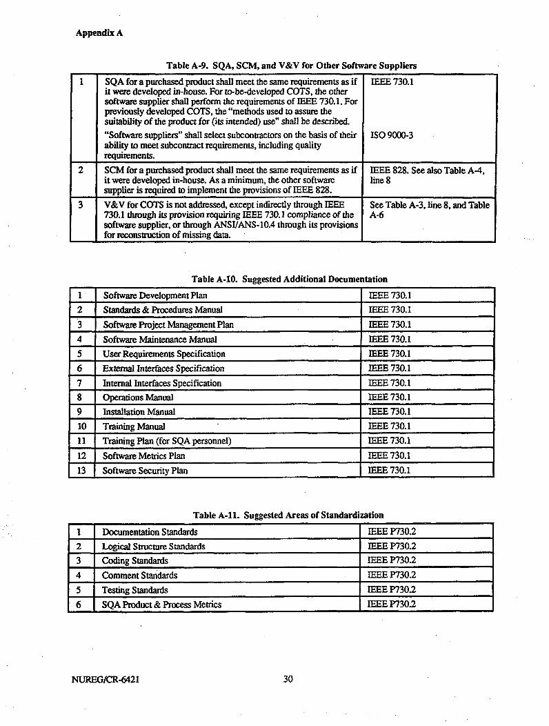
Appendix A
Table A-9. SQA, SCM, and V&V for Other Software Suppliers
I SQA for a purchased product shall meet the same requirements as if IEEE 730.1it were developed in-house. For to-be-developed COTS, the othersoftware supplier shall perform the requirements of IEEE 730.1. Forpreviously developed COTS, the "methods used to assure thesuitability of the product for (its intended) use" shall be described.
"Software suppliers" shall select subcontractors on the basis of their ISO 9000-3ability to meet subcontract requirements, including qualityrequirements.
2 SCM for a purchased product shall meet the same requirements as if IEEE 828. See also Table A-4,it were developed in-house. As a minimum, the other software line 8supplier is required to implement the provisions of IEEE 828.
3 V&V for COTS is not addressed, except indirectly through IEEE See Table A-3, line 8, and Table730.1 through its provision requiring IEEE 730.1 compliance of the A-6software supplier, or through ANSI/ANS-10.4 through its provisionsfor reconstruction of missing data.
Table A-10. Suggested Additional Documentation
1 Software Development Plan IEEE 730.1
2 Standards & Procedures Manual IEEE 730.1
3 Software Project Management Plan IEEE 730.1
4 Software Maintenance Manual IEEE 730.1
5 User Requirements Specification IEEE 730.1
6 External Interfaces Specification IEEE 730.1
7 Internal Interfaces Specification IEEE 730.18 Operations Manual IEEE 730.1
9 Installation Manual IEEE 730.1
10 Training Manual IEEE 730.1
II Training Plan (for SQA personnel) IEEE 730.1
12 Software Metrics Plan IEEE 730.1
13 Software Security Plan IEEE 730.1
Table A-11. Suggested Areas of Standardization
I Documentation Standards IEEE P730.2
2 Logical Structure Standards IEEE P730.2
3 Coding Standards IEEE P730.2
4 Comment Standards IEEE P730.25 Testing Standards IEEE P730.2
6 SQA Product & Process Metrics IEEE P730.2
NUREG/CR-6421 30
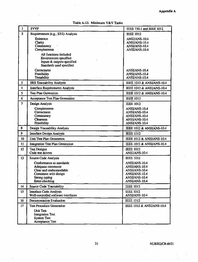
Appendix A
Table A-12. Minimum V&V Tasks
I SVVP IEEE 730.1 and IEEE 1012
2 Requirements (e.g., SRS) Analysis IEEE 1012
Existence ANSI/ANS-10.4Clarity ANSI/ANS-10.4Consistency ANSI/ANS-10.4Completeness ANSI/ANS-10.4
All functions includedEnvironment specifiedInputs & outputs specifiedStandards used specified
Correctness ANSI/ANS-10.4Feasibility ANSI/ANS-10.4Testability ANST/ANS-10.4
3 SRS Traceability Analysis IEEE 1012 & ANSI/ANS-10.4
4 Interface Requirements Analysis IEEE 1012 & ANSI/ANS-10.4
5 Test Plan Generation IEEE 1012 & ANSI/ANS-10.4
6 Acceptance Test Plan Generation IEEE 1012
7 Design Analysis IEEE 1012
Completeness ANSI/ANS-10.4Correctness ANSI/ANS-10.4Consistency ANSJ/ANS-10.4Clearness ANSIIANS-10.4Feasibility ANSI/ANS-10.4
8 Design Traceability Analysis IEEE 1012 & ANSI/ANS-10A
9 Interface Design Analysis IEEE 1012
10 Unit Test Plan Generation IEEE 1012& ANSI/ANS-10.4
11 Integration Test Plan Generation IEEE 1012 & ANSI/ANS-10.4
12 Test Designs IEEE 1012Code test drivers ANSI/ANS-10.4
13 Source Code Analysis IEEE 1012
Conformance to standards ANSI/ANS-10.4Adequate comments ANSI/ANS-10.4Clear and understandable ANSI/ANS-10.4Consistent with design ANSI/ANS-10.4Strong typing ANSI/ANS-10.4Error-checking ANSI/ANS-10.4
14 Source Code Traceability IEEE 1012
15 Interface Code Analysis IEEE 1012Well-controlled software interfaces ANSI/ANS-10.4
16 Documentation Evaluation IEEE 1012
17 Test Procedure Generation IEEE 1012 &ANSI/ANS-10.4
Unit TestIntegration TestSystem TestAcceptance Test
31 NUREG/CR-6421
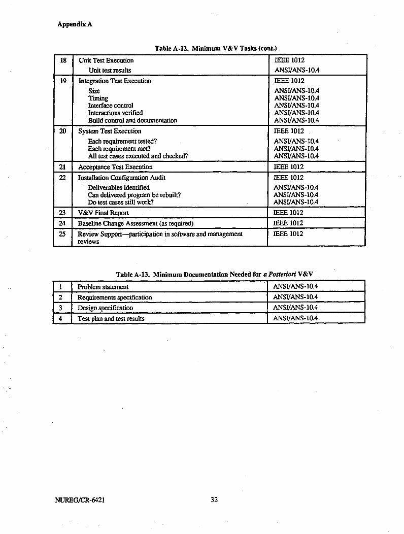
Appendix A
Table A.12. Minimum V&V Tasks (cont.)
18 Unit Test Execution IEEE 1012
Unit test results ANSI/ANS-10.4
19 Integration Test Execution IEEE 1012
Size ANSIWANS-10.4Timing ANSI/ANS-10.4Interface control ANSI/ANS-10.4Interactions verified ANSI/ANS-10.4Build control and documentation ANSIIANS-10.4
20 System Test Execution IEEE 1012
Each requirement tested? ANSI/ANS-10.4Each requirement met? ANSI/ANS-10.4All test cases executed and checked? ANSI/ANS-10.4
21 Acceptance Test Execution IEEE 1012
22 Installation Configuration Audit IEEE 1012
Deliverables identified ANSI/ANS-10.4Can delivered program be rebuilt? ANSI/ANS-10.4Do test cases still work? ANSI/ANS-10.4
23 V&V Final Report IEEE 1012
24 Baseline Change Assessment (as required) IEEE 1012
25 Review Support-participation in software and management IEEE 1012reviews
Table A-13. Minimum Documentation Needed for a Posteriori V&V
1 Problem statement j ANSI/ANS-10.4
2 Requirements specification ANSI/ANS-10.4
3 Design specification ANSI/ANS-10.4
4 Test plan and test results ANSI/ANS-10.4
NUREG/CR-6421 332

Appendix A
Table A-14. Typical Policies and Directives of a Configuration Management Operation
1 Definition of software levels or classes IEEE 828
2 Naming conventions IEEE 828
3 Version ID conventions IEEE 828
4 Product ID policy IEEE 828
5 IDs of specifications, test plans, manuals & documents IEEE 828
6 Media ID and file management IEEE 828
7 Documentation release process IEEE 828
8 Software release to general library IEEE 828
9 Problem reports, change requests and orders IEEE 828
10 Structure & operation of CCBs IEEE 828
11 Acceptance or release of software products IEEE 828
12 Operating rules for the software library IEEE 828
13 Audit policy IEEE 828
14 Methods for CCB assessment of change impact IEEE 828
15 Level of testing or assurance required before an item is accepted for IEEE 828CM--may be related to software classes
16 Level of SQA or V&V required before an item is accepted for IEEE 828CM-may be related to software classes
33 NUREG/CR-6421


Appendix B: Testing Existing Softwarefor Safety-Related Applications
Prepared byJohn A. ScottJ. Dennis Lawrence
Lawrence Livermore National Laboratory7000 East AvenueLivermore, CA 94550
Prepared forU.S. Nuclear Regulatory Commission


Appendix B
ABSTRACT
The increasing use of commercial off-the-shelf (COTS) software products in digital safety-critical applications israising concerns about the safety, reliability, and quality of these products. One of the factors involved in addressingthese concerns is product testing. A tester's knowledge of the software product will vary, depending on theinformation available from the product vendor. In some cases, complete source listings, program structures, andother information from the software development may be available. In other cases, only the completehardware/software package may exist, with the tester having no knowledge of the internal structure of the software.
The type of testing that can be used will depend on the information available to the tester. This report describes sixdifferent types of testing, which differ in the information used to create the tests, the results that may be obtained,and the limitations of the test types. An Annex contains background information on types of faults encountered intesting, and a Glossary of pertinent terms is also included.
37 37 NUREG/CR-6421


Appendix B
CONTENTS
1. Inltroductionf....................................................................o................................................... 451.1. Purpose ............................................................................................................ 451.2. Scope, Assumptions and Limitations......................................................45.
1.3. Reort Oranizatin................................................. 45
1.4. Definitions......................................................................................................... 461.5. General Comments on Testing................................................................................... 46
1.5.1. Testing Goals and Software Qualities ................................................................... 461.5.2. Software Objects ......................................................................................... 461.5.3. Testers..................................... ............... 491.5.4. The Testing Life Cycle .................................................................................. 49
1.6. Faults, Errors, Failures ........................................................................................... 511.6.1 Definitions..................................................................................... e............ 511.6.2 Relationship of Faults, Errors, and Failures ............................................................. 51
1.7. Selection of Testing Strategies and Techniques ................................................................ 521.7.1. Context for Selecting Testing Strategies ................................................................ 521.7.2. Considerations for Selecting Testing Strategies........................................................ 52
2. Static Source Code Analysis............................................................................................. 592.1. Purpose of Static Source Code Analysis ......................................................................... 592.2. Benefits and Limitations of Static Source Code Analysis...................................................... 59
2.2. 1. Benefits ................................................................................................... 592.2.2. Limitations................................................................................................. 59
2.3. Information Required to Perform Static Source Code Analysis ............................................... 602.4. Methods of Performing Static Source Code Analysis .......................................................... 60
2.4.1. Static Analysis Planning and Requirements ............................................................ 6(02.4.2. Analysis Design and Implementation ................................................................... 602.4.3. Execution and Evaluation of the Analyses .............................................................. 61
2.5. Discussion of Static Source Code Analysis ..................................................................... 612.5. 1. Inspection.................................................................................................. 612.5.2. Desk Checking............................................................................................ 632.5.3. Automated Structural Analysis .......................................................................... 642.5.4. Other Methods ............................................................................................ 64
3. Structural Testing ........................................................................................................ 673.1. Purpose of StructuralTesting .................................................................................... 673.2. Benefits and Limitations of Structural Testing.................................................................. 67
3.2.1. Benefits ................................................................................................... 673.2.2. Limitations................................................................................................ 67
3.3. Information Required to Perform Structural Testing ........................................................... 673.4. Methods of Performing Structural Testing...................................................................... 67
3.4.1. Test Planning and Test Requirements................................................................... 673.4.2. Test Design and Test Implementation................................................................... 683.4.3. Test Execution and Test Evaluation..................................................................... 68
3.5. Discussion of Structural Testing................................................................................. 693.5. 1. Control Flowgraphs ...................................................................................... 693.5.2. Control Flow (Path) Testing............................................................................. 703.5.3. Loop Testing.............................................................................................. 713.*5.4. Data Flow Testing........................................................................................ 71
4. Functional Testing........................................................................................................ 754.1. Purpose of Functional Testing ................................................................................... 75
.39 NUREG/CR-6421

Appendix B
4.2. Benefits and Limitations of Functional Testing................................................................. 754.2.1. Benefits ................................................................................................... 754.2.2. Limitations................................................................................................ 75
4.3. Information Required to Perform Functional Testing........................................................... 754.4. Methods of Performing Functional Testing ..................................................................... 75
4A.4.. Test Planning and Test Requirements ................................................................... 754.4.2. Test Design and Test Implementation................................................................... 764.4.3. Test Execution and Test Evaluation ..................................................................... 76
4.5. Discussion of Functional Testing ................................................................................ 774.5. 1. Transaction Testing....................................................................................... 774.5.2. Domain Testing........................................................................................... 784.5.3. Syntax Testing ............................................................................................ 794.5A4. Logic-Based Testing ..................................................................................... 804.5.5. State Testing .............................................................................................. 81
5. Statistical Testing ........................................................................................................ 835.1. Purpose of Statistical Testing..................................................................................... 835.2. Benefits and Limitations of Statistical Testing.................................................................. 83
5.2.1. Benefits ................................................................................................... 835.2.2. Limitations................................................................................................ 83
5.3. Information Required to Perform Statistical Testing ........................................................... 835.4. Methods of Performing Statistical Testing...................................................................... 84
5.4.1. Test Planning and Test Requirements ................................................................... 845.4.2. Test Design and Test Implementation................................................................... 845.4.3. Test Execution and Test Evaluation ..................................................................... 86
5.5. Discussion of Statistical Testing................................................................................. 866. Stress Testing...........................................................I.................................................. 89
6.1. Purpose of Stress Testing ......................................................................................... 896.2. Benefits and Limitations of Stress Testing...................................................................... 89
6.2.1. Benefits ................................................................................................... 896.2...2. ittLimitations ................................................................... 89*****"**'*... *"**** 8
6.3. Information Required to Perform Stress Testing................................................................ 896.4. Methods of Performing Stress Testing .......................................................................... 90
6A.4.. Test Planning and Test Requirements................................................................... 906.4.2. Test Design and Test Implementation ......... ........................................................ 906.4.3. Test Execution and Test Evaluation ..................................................................... 91
6.5. Discussion of Stress Testing ..................................................................................... 927. Regression Testing....................................................................................................... 95
7.1. Purpose of Regression Testing................................................................................... 957.2. Benefits and Limitations of Regression Testing................................................................. 95
7.2.1. Benefits ................................................................................................... 957.2.2. Limitations................................................................................................ 95
7.3. Informnation Required to Perform Regression Testing.......................................................... 957.4. Methods of Performing Regression Testing....................... ........... 95
7A.4.. Test Planning and Test Requirements................................................................... 957.4.2. Test Design and Test Implementation................................................................... 957.4.3. Test Execution and Test Evaluation ..................................................................... 96
7.5. Discussion of Regression Testing................................................................................ 968. References................................................................................................................. 97Annex-Taxonomy of Software Bugs ..................................................................................... 99G losossary ...... ............................................................................................................ 1090
NUREG/CR-6421 40
Appendix B
TABLES
Table 1-1. Safety Impact of Software Qualities from a Regulator Viewpoint........................................... 47Table 1-2. Testing Strategies Appropriate to Software Qualities........................................................ 48Table 1-3. Test Strategies Appropriate for Software Objects............................................................. 50Table 1-4. Expected Pattern of Testers and Software Objects ........................................................... 50Table 1-5. Strategies Used by Testers ..................................................................................... 50Table 1-6. Sample Prerequisites for and Extent of Testing............................................................... 53Table 1-7. Typical Testing Strategies for Investigating Software Qualities ............................................ 55Table 3-1. Data Flow Testing Symbols and Meanings ................................................................... 73Table 5-1. Required Number of Test Cases to Achieve Stated Levels of Failure Rate and Confidence............... 85Table 5-2. Expected Test Duration as a Function of Test Case Duration ............................................... 85
FIGURES
Figure 2-1. Conceptual Platform for Automated Static Analysis........................................................ 62Figure 2-2. Software Development Activities, Products, and Inspections .......................................... ....63Figure 3-1. Typical Test Station Components for Structural Testing ................................................... 69Figure 3-2. Example of a Program......................................................................................... 70Figure 3-3. Flowgraph Corresponding to the Module in Figure 3-2..................................................... 71Figure 3-4. Examples of Loops in Flowgraphs ........................................................................... 72Figure 3-5. Test Cases in Loop Testing.................................................................................... 72Figure 3-6. Control Flowgraph Augmented to Show Data Flow ........................................................ 74Figure 4- 1. Typical Test Station Components for Functional Testing................................................... 77Figure 4-2. Example of a Transaction Flowgraph......................................................................... 78Figure 4-3. Example of Domains .......................................................................................... 79Figure 4-4. Examples of Two-Dimensional Domains with Examples of Test Values ................................. 80Figure 4-5. Example of a Syntax Graph................................................................................... 80Figure 4-6. Example of a Decision Table ................................................................................. 81Figure 4-7. Example of a State Transition Diagram...................................................................... 82Figure 5-1. Typical Test Station Components for Statistical Testing ................................................... 86Figure 6- 1. Typical Test Station Components ............................................................................ 91
41 4 NUIREG/CR-6421

Appendix B
ACKNOWLEDGMENT
The authors thank and acknowledge Professor Richard Hamlet for reviewing this report and providing helpfulinsights and comments.
43 NUREG/CR-6421


Appendix B
TESTING EXISTING SOFTWARE FORSAFETY-RELATED APPLICATIONS
1. INTRODUCTION
1.1. Purpose
The increasing use of commercial off-the-shelf(COTS) software products in digital safety-criticalapplications is raising concerns about the safety,reliability, and quality of these products. One of thefactors involved in addressing these concerns isproduct testing. A tester's knowledge of the softwareproduct will vary, depending on the informationavailable from the product vendor. In some cases,complete source listings, program structures, and otherinformation from the software development may beavailable. In other cases, only the completehardware/software package may exist, with the testerhaving no knowledge of the internal structure of thesoftware.
The type of testing that can be used will depend on theinformation available to the tester. This reportdescribes six different types of testing, which differ inthe information used to create the tests, the results thatmay be obtained, and the limitations of the test types.An annex contains background information on types offaults encountered in testing, and a Glossary ofpertinent terms is also included.
1.2. Scope, Assumptions and Limitations
This report specifically addresses testing of existing,commercial off-the-shelf software for safety-relatedapplications and, therefore, makes no assumptions as tothe adequacy of the software process under which thesoftware was developed or of the capabilities of thesoftware developer. These and other questions must beconsidered by whatever process determines theacceptability of the COTS software product for aparticular use. Testing is only one aspect of anacceptance process for a COTS software product.Other aspects include a system design that carefullyallocates responsibilities to the computer system, ahazard analysis of the system (including computerhardware and software), an investigation of thecapabilities of the software developer, a maturedevelopment process, and favorable experience data.These aspects are discussed in the main report in thisNUREG/CR, and related information is found inLawrence (1993), Lawrence and Preckshot (1994), andPreckshot and Scott (1995). Results obtained from
applying testing strategies discussed in this report will,therefore, be used in combination with data from theother information sources used in the acceptanceprocess.
This report provides an overview of key testingtechniques and their relationship to COTS software.The quoted references should be consulted for moredetail. In particular, Beizer (1990) and Marick (1995)provide detailed, practical information on carrying outtesting activities.
1.3. Report Organization
The body of the report consists of six sections,numbered 2-7, which describe six different testingstrategies. Within each testing strategy, a numberspecific testing techniques are described. The testingstrategies are:
* Static Source Code Analysis
* Structural Testing
* Functional Testing
* Statistical Testing
* Stress Testing
* Regression Testing.
Each of these sections is organized in a similar fashion:
" Purpose of the testing strategy
" Benefits and limitations of the testing strategy
" Information required to perform the tests
" Methods of performing the tests
" Discussion of the test techniques belonging to thetesting strategy.
The sections are meant to be read independently, sosome repetition of material occurs throughout sections2-7.
An Annex has been included to provide additionalinformation regarding the types of faults discovered
45 NUREG/CR-6421

Appendix B
during testing, as well as a Glossary of software qualityterms.
1.4. Definitions
Several terms used in this report are defined here. TheGlossary provides a more complete listing ofapplicable terminology.
Commercial Off-the-Shelf (COTS) software.COTS software is developed for generalcommercial use and, as such, is usually developedwithout knowledge of the unique requirements ofparticular applications. The term COTS, as usedhere, does not denote an acceptance process nordoes it have any connotations regarding theavailability of source code or development processrecords.
Operational Profile. The operational profile of aprogram is the statistical distribution function ofthe inputs which will be encountered by theprogram under actual operating conditions.
" Oracle. Any (often automated) means of judgingthe correctness of a test execution. 1
• Software Object. The software module, package,program, subsystem, or system which is beingtested.
" Testing. "(1)The process of operating a system orcomponent under specified conditions, observingor recording the results, and making an evaluationof some aspect of the system or component. (2)The process of analyzing a software item to detectthe differences between existing and requiredconditions (that is, bugs) and to evaluate thefeatures of the software items." (IEEE 610.12-1990) In this report, the word "testing" is used inboth meanings.
1.5. General Comments on Testing
This section contains brief comments on softwaretesting that apply generally to the remainder of thereport. Note that the tables of Section 1 should not beread as absolutes, but as general guidance. In particularcases, some connections indicated in the tables may notbe relevant, and some connections that are notindicated in the tables may be important. Nevertheless,in most cases, the tables provide general guidance fortesting safety-related COTS software.
'A more resuictive definition is given by Beizer (1990) who states,"An oracle is any program, process, or body of data that specifies theexpected outcome of a set of tests as applied to a tested object...The most common oracle is an input/outcome oracle-an oracle thatspecifies the expected outcome for a specified input." This is moredifficult to create and is not necessary to this report.
1S..1. Testing Goals and Software Qualities
To be effective, testing should be directed at measuringsome quality of the software. The various testingstrategies address different sets of software qualities.For this reason, a comprehensive testing program willincorporate as many strategies as possible in an attemptto assess the overall soundness of the software. Withinthis context, special emphasis can be placed on thosestrategies that are related to quality attributes ofparticular concern.
Hetzel (1984) divides software qualities into three sets:external, internal, and future. External qualitiesdescribe the functionality of the software; internalqualities describe the engineering aspects of thesoftware; and future qualities describe the adaptabilityof the software. Many possible software qualities havebeen described in the software engineering literature. Alist of qualities collected by Hetzel (1984) and byCharette (1989) has been arranged by the likely impactof the qualities on safety in Table 1-1. Definitions ofthese qualities are given in the Glossary.
The six different testing strategies are not equallysuited to all of the software qualities. Table 1-2suggests which strategies to use for the qualities thatare of primary and secondary interest in safety-relatedreactor applications. The table provides a crossreference between software qualities and strategiesused to test for these qualities. These linkages can beuseful to both developers and evaluators of COTSsoftware. Regression testing attempts to ensure thatchanges made to the software, either duringdevelopment or after installation, do not affect asoftware object in unplanned areas. It consists of re-execution of previous testing and, therefore, addressesthe qualities previously demonstrated with other formsof testing.
1.5.2. Software Objects
Software objects subject to testing range fromprogramming language statements to completesystems, and the type and amount of testing willgenerally vary across this range. To provide someconsistency within this report, five classes of objectsare defined. In particular instances, some classes maycoalesce. For example, in the simplest case of a systemconsisting of a single module, all five classes arecompressed into one. Most classes will be distinct insafety-critical systems.
Software object terminology is defined forconventional third-generation programming languagessuch as Ada, C, C++, Pascal, and FORTRAN.Extensions to fourth-generation languages and visualprogramming environments should be straightforward.
NUREG/CR-6421 46
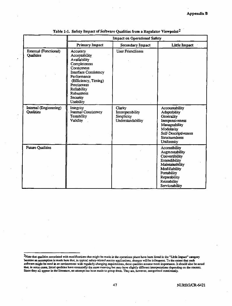
Appendix B
Table 1-1. Safety Impact of Software Qualities from a Regulator Viewpoint 2
Impact on Operational Safety
Primary Impact Secondary Impact Little Impact
External (Functional) Accuracy User FriendlinessQualities Acceptability
AvailabilityCompletenessCorrectnessInterface ConsistencyPerformance(Efficiency, Timing)
PrecisenessReliabilityRobustnessSecurityUsability
Internal (Engineering) Integrity Clarity AccountabilityQualities Internal Consistency Interoperability Adaptability
Testability Simplicity GeneralityValidity Understandability Inexpensiveness
ManageabilityModularitySelf-DescriptivenessStructurednessUniformity
Future Qualities AccessibilityAugmentabilityConvertibilityExtendibilityMaintainabilityModifiabilityPortabilityReparabilityReusabilityServiceability
2 Note that qualities associated with modifications that might be made in the operations phase have been listed in the "Little Impact" categorybecause an assumption is made here that, in typical safety-related reactor applications, changes will be infrequent. To the extent that suchsoftware might be used in an environment with regularly changing requirements, these qualities assume more importance. It should also be notedthat, in some cases, listed qualities have essentially the same meaning but may have slightly different interpretations depending on the context.Since they all appear in the literature, no attempt has been made to group them. They arc, however, categorized consistently.
47 47 NUREG/CR-6421

Appendix B
Table 1-2. Testing Strategies Appropriate to Software Qualities
Software Quality Static I Structural Functional Statistical Stress Testing__ Analysis Testing Testing Testing
Acceptability X 0Accuracy 0 X X
Availability X X
Clarity X
Completeness X X 0
Correctness X X X X
Integrity 0 X X
Interface Consistency X X
Internal Consistency X X 0
Interoperability X X
Performance (efficiency 0 X X& timing) I
Preciseness 0 X X
Reliability X
Robustness 0 X X
Security 0 X XSimplicity X
Testability X
Understandability X
Usability X X
User Friendliness X
Validity X X
Regression Testing _ _ _ 0 X 0 X
X = Strategy should be used for the specified quality0 = Strategy may be used for the specified quality
A module is a named collection of programminglanguage statements. Alternate names aresubroutine, procedure, or unit.
A package is a collection of one or more moduleswhich relate to a common topic. Packages are akey feature of object-oriented programminglanguages such as Ada and C++. For example, aset of modules that processes dates could becombined into a calendar package. A set ofmodules that manages sensor information (read,check status, convert data) could be combined intoa sensor device-driver package.
A program is a set of one or more packages andmodules which can be executed on a computer.
Programs are created by means of a linker orloader and can be stored in a file or PROM 3 forfuture use.
A subsystem consists of one or more modules,packages and programs which are devoted to oneor more related functions, or which must executetogether to achieve a desired task, or whichexecute concurrently on the same processor.Examples include a set of programs whichperforms various kinds of report production, and aset of programs which reads and processes sensor
3 Programmable read-only memory.
NUREG/CR-6421 48

Appendix B
data on one computer and sends the results to bedisplayed on another computer.
• A system is the entire set of subsystems whichmanages a complete application.
Table 1-3 shows a different perspective. It matchesdifferent test strategies to different classes of softwareobjects. The checked entries show which testingstrategies are primarily recommended for each class ofobject. Note that any strategy could apply to any classof object under specific circumstances. The tablemerely provides general guidance.
Objects are classified here according to structure, andthis classification is used throughout the report.Another method of classification relates to structuralcomplexity. This might yield a series such as batchprocessing, interactive time-sharing, transactionprocessing, real-time process control, and real timevehicle control. However, this report is limited to realtime process control systems.
A further classification dimension involves theinteraction of processes and ranges from single processsystems to multiple-process shared-memory concurrentsystems. This dimension affects primarily the amountof testing required and the difficulty of creating andjudging the tests. In particular, stress testing is veryimportant as the amount of interaction increases.
1.5.3. Testers
Testing is frequently carried out by different categoriesof personnel. A primary concern when safety is anissue is independence of testing from development.4
4 lndependent V&V is used when it is necessary to have an impartial,objective analysis and test conducted of the software/system. Thenotion is that difficult-to-discover errors which may reside in thesoftware due to assumptions or technical biases inadvertentlyintroduced by the development team would have a higher probabilityof being detected by an impartial, objective V&V team who wouldapply a fresh viewpoint to the software. IV&V is used for high -criticality software, which demands the integrity of critical functionsdue to life-threatening consequences of failure, unrecoverablemission completion (e.g., space probes), safety or securitycompromises, financial loss, or unacceptable social consequences.Independence is defined by three parameters: technical, managerial,and financial The degree of independence of the V&V effort isdefined by the extent that each of the three independence parametersis vested in the V&V organization. The ideal IV&V contains allthree independence parameters. Technical independence requires thatthe IV&V team (organization or group) utilize personnel who are notinvolved in the development of the software. An effective IV&Vteam has personnel who have some knowledge about the system orwhose related experience and engineering background gives themthe ability to quickly learn the system. In all instances, the IV&Vteam must formulate its own understanding of the problem and howthe proposed system is solving the problem. This technicalindependence ("fresh viewpoint") is crucial to the IV&V team'sability to detect the subtle errors that escape detection bydevelopment testing and quality assurance reviewers. (Personalcommunication on work being done on the update of IEEE 1012).
During development, the software engineer whodevelops code may be involved in some of the testing.Some independence can be achieved by using othersoftware engineers from the developing organization.Greater independence can be achieved if the customeror an IV&V organization performs testing activities. Inthese cases, testing could be subcontracted. Forexample, the customer might hire a company to carryout testing on its behalf or it might do the testing itself.When COTS software is to be tested by the customer,it is unlikely that parties from the developingorganization will be involved in the testing effort, soindependence would generally be assured. In any case,note that it is essential that the testers be well-qualifiedand knowledgeable of the application.
Table 14 shows which categories of tester are mostlikely to carry out testing on the different types ofsoftware objects. As with the previous tables,exceptions do occur. For example, a programmer couldcarry out all testing strategies.
Table 1-5 similarly shows which categories of testersare likely to use the different testing strategies. Again,these are recommendations, not absolutes.
1.5.4. The Testing Life Cycle
Software testing has a life cycle of its own that issimilar to the software development life cycle. Testinglife cycle phases generally include planning,requirements, design, implementation, and operation(execution). Note that V&V activities apply to testinglife cycle products (reviews of test plans & designs,etc.) in addition to software development life cycleproducts.
If testing is carried out by or on behalf of thedevelopment organization, the testing life cycle phasesshould occur concurrently with the development lifecycle phases. This is not likely to be possible withcustomer testing of COTS software. However, thetesting life cycle should still exist and be carried out.
Testing life cycle activities are described in detail inIEEE Software Engineering Standards 829 and 1074and are not discussed here. The following list providesa brief synopsis of the activities based on thesestandards, assuming that the testing will be carried outby (or on behalf of) the customer.* Test planning activities
- Prepare test plan
* Test requirements activitiesDetermine the software qualities for whichtesting is required
- Determine the software objects to be tested
- Obtain needed resources: budget, time, andassignment of personnel
49 NUREG/CR-6421
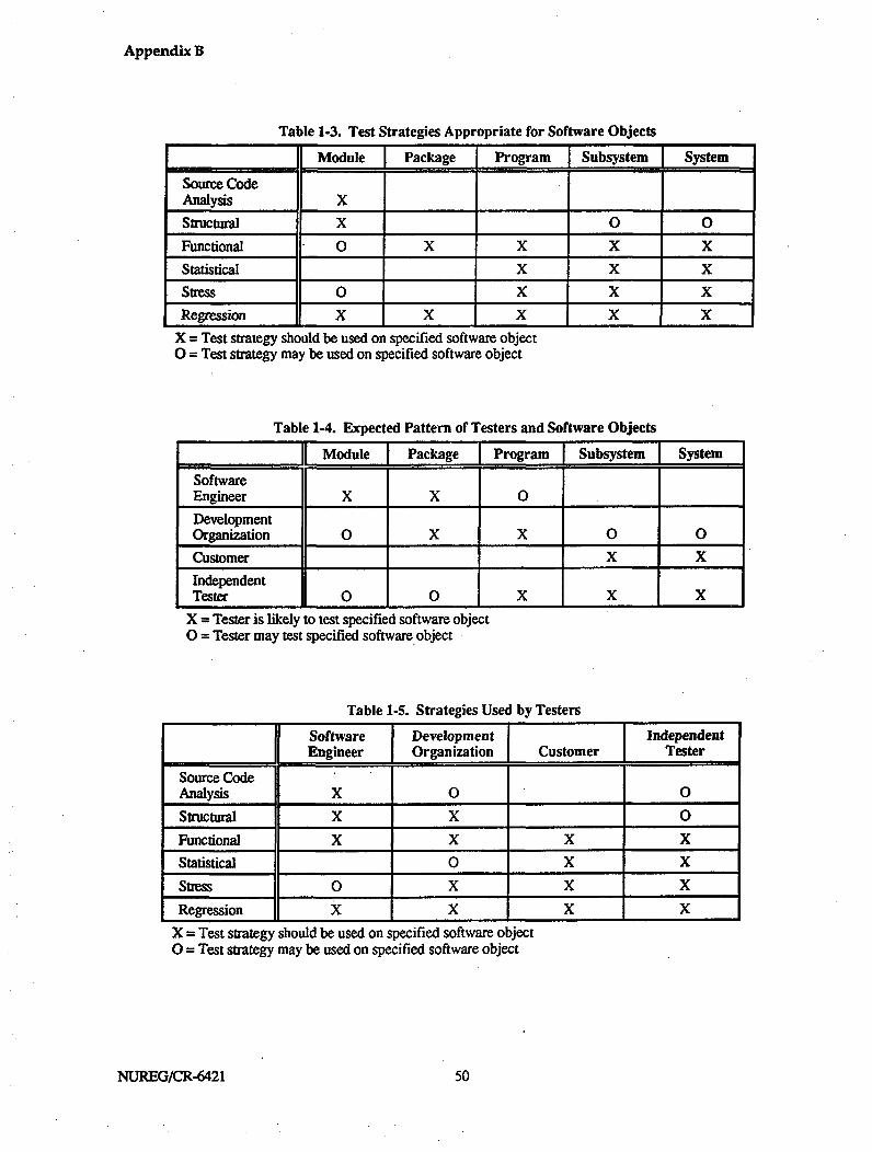
Appendix B
Table 1-3. Test Strategies Appropriate for Software Objects
_ _ Module I Package I Program Subsystem System
Source CodeAnalysis X
Structural X 0 0
Functional 0 X X X X
Statistical X X X
Stress 0 X X X
Regression X X X X X
X = Test strategy should be used on specified software object0 = Test strategy may be used on specified software object
Table 1-4. Expected Pattern of Testers and Software Objects
Module Package Program Subsystem System
SoftwareEngineer X X 0
DevelopmentOrganization 0 X X 0 0
Customer X X
IndependentTester 0 0 X X X
X = Tester is likely to test specified software object0 = Tester may test specified software object
Table 1-5. Strategies Used by Testers
II Software jDevelopment 11 IndependentEngineer Organization Customer Tester
Source CodeAnalysis X 0 0
Structural X X 0
Functional X X X X
Statistical 0 X X
Stress 0 X X X
Regression X X X X
X = Test strategy should be used on specified software objectO = Test strategy may be used on specified software object
NUREG/CR-6421 550
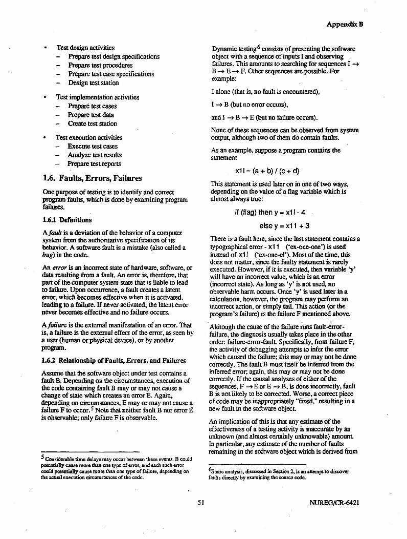
Appendix B
* Test design activities- Prepare test design specifications- Prepare test procedures- Prepare test case specifications- Design test station
" Test implementation activities- Prepare test cases- Prepare test data- Create test station
" Test execution activities- Execute test cases- Analyze test results- Prepare test reports
1.6. Faults, Errors, Failures
One purpose of testing is to identify and correctprogram faults, which is done by examining programfailures.
1.6.1 Definitions
A fault is a deviation of the behavior of a computersystem from the authoritative specification of itsbehavior. A software fault is a mistake (also called abug) in the code.
An error is an incorrect state of hardware, software, ordata resulting from a fault. An error is, therefore, thatpart of the computer system state that is liable to leadto failure. Upon occurrence, a fault creates a latenterror, which becomes effective when it is activated,leading to a failure. If never activated, the latent errornever becomes effective and no failure occurs.
A failure is the external manifestation of an error. Thatis, a failure is the external effect of the error, as seen bya user (human or physical device), or by anotherprogram.
1.6.2 Relationship of Faults, Errors, and Failures
Assume that the software object under test contains afault B. Depending on the circumstances, execution ofthe code containing fault B may or may not cause achange of state which creates an error E. Again,depending on circumstances, E may or may not cause afailure F to occur. 5 Note that neither fault B nor error Eis observable; only failure F is observable.
Considerable time delays may occur between these events. B couldpotentially cause more than one type of error, and each such errorcould potentially cause more than one type of failure, depending onthe actual execution circumstances of the code.
Dynamic testing 6 consists of presenting the softwareobject with a sequence of inputs I and observingfailures. This amounts to searching for sequences I --B -- E -- F. Other sequences are possible. Forexample:
I alone (that is, no fault is encountered),
I -ý B (but no error occurs),
and I -> B -o E (but no failure occurs).
None of these sequences can be observed from systemoutput, although two of them do contain faults.
As an example, suppose a program contains thestatement
xlI = (a + b) / (c + d)
This statement is used later on in one of two ways,depending on the value of a flag variable which isalmost always true:
if (flag) then y = xl I - 4
elsey=xll +3
There is a fault here, since the last statement contains atypographical error - xl 1 ('ex-one-one') is usedinstead of xl I ('ex-one-el'). Most of the time, thisdoes not matter, since the faulty statement is rarelyexecuted. However, if it is executed, then variable 'y'will have an incorrect value, which is an error(incorrect state). As long as 'y' is not used, noobservable harm occurs. Once 'y' is used later in acalculation, however, the program may perform anincorrect action, or simply fail. This action (or theprogram's failure) is the failure F mentioned above.
Although the cause of the failure runs fault-error-failure, the diagnosis usually takes place in the otherorder: failure-error-fault. Specifically, from failure F,the activity of debugging attempts to infer the errorwhich caused the failure; this may or may not be donecorrectly. The fault B must itself be inferred from theinferred error; again, this may or may not be donecorrectly. If the causal analyses of either of thesequences, F --- E or E -> B, is done incorrectly, faultB is not likely to be corrected. Worse, a correct pieceof code may be inappropriately "fixed," resulting in anew fault in the software object.
An implication of this is that any estimate of theeffectiveness of a testing activity is inaccurate by anunknown (and almost certainly unknowable) amount.In particular, any estimate of the number of faultsremaining in the software object which is derived from
6 Static analysis, discussed in Section 2, is an attempt to discoverfaults directly by examining the source code.
51 NUREG/CR-6421

Appendix B
testing is imprecise by an unknown amount. Thisshould not be surprising-similar effects can beobserved in science anytime inductive reasoning isused.
It is widely believed by software engineers that aproperly designed test program can reduce theuncertainties in testing effectiveness sufficiently thatthey can be acceptably ignored. The operative wordsare "properly" and "believed." The first word is itselfill-defined, while "belief' lacks the confidence thatcomes with scientific or mathematical proof. A finalpoint is that extending a general belief (that appliesgenerally to testing) to a specific software object undertest adds an additional inference of unknowableuncertainty.
These observations apply to all dynamic testingstrategies discussed below except statistical testing.The latter is inherently interested in failures rather thanfaults,, so the argument does not apply. This argumenthelps explain, however, why testing can never beperfect.
1.7. Selection of Testing Strategies andTechniques
This section discusses the context and goals associatedwith the testing of COTS software and providesguidelines for applying the various testing strategiesdiscussed in the following sections.
1.7.1. Context for Selecting Testing Strategies
The testing of a COTS software item is normally donewithin the context of a larger process whose goal is~todetermine the acceptability or non-acceptability of theCOTS software for use in a particular application.Consequently, this report does not address the issue ofdetermining acceptance criteria for the use of a COTSsoftware item in a particular application. It is assumedthat the acceptance process will identify specific needsto be addressed with testing, that this report will serveas a reference for planning and conducting thenecessary testing, and that the results will be evaluated,with other information, within the context of theacceptance process.
A COTS software item might be tested in order to gainadditional information about the product itself or toexamine the behavior of the product in the plannedapplication. In general, the more important a COTSsoftware item is to safety, the less one would expect toneed after-the-fact COTS software testing to augmentother information in order to demonstrate acceptability.In other words, the COTS software item should alreadybe demonstrably well-qualified for its intended role. Inthis case, testing activities will probably be narrowlyfocused on particular qualities or attributes of thesoftware. For items less important to safety, it may be
appropriate (depending on the specifics of theacceptance process) to rely to a larger degree on after-the-fact testing, and a more comprehensive testingeffort might be appropriate. Regardless of the scope ofany potential testing effort, it will be useful to obtaininformation about past and current faults as well asconfiguration and operating parameters, reliability andavailability, and comments about other qualities basedon the experience of users of the COTS software item.
In addition to augmenting the testing effort conductedduring software development, there might also be newrequirements specific to the intended use of the COTSsoftware item that should be addressed with testing.These might be related to particular safety functions tobe performed, special performance constraints,adaptation to new hardware platforms, particularstandards adopted for the application, or a need fordemonstrating high confidence in particular softwarequalities. In these cases, the appropriate strategies mustbe selected to address the areas of concern. This testingeffort could be quite extensive. For example, functionaltesting might be used to verify that certain functionsare handled correctly, stress testing might be used toexamine performance in the target environment, andstatistical testing could be applied to assess reliability.
1.7.2. Considerations for Selecting TestingStrategies
This subsection provides assistance in selecting testingstrategies and techniques to meet the needs defined bya COTS acceptance process. Since there may bemultiple techniques that will address a particulartesting question, and since it is not possible toanticipate all types of questions that might arise invarious situations, the information provided must beconsidered as guidance rather thani as a prescriptiveformula. It should also be noted that this section refersto traditional third-generation languages (e.g., Ada, C,C++, Fortran, and Pascal) and does not necessarilyapply specialized or developing technologies such asartificial intelligence systems.
The process of selecting testing strategies for a COTSsoftware item is constrained by the informationavailable. Table 1-6 presents a summary of theminimum information required for the various testingstrategies. Representative information is also providedregarding the extent of testing to be applied when usinga particular testing strategy; refer to the appropriatesection for more detail. Table 1-6 provides a first-orderestimate of the prerequisites and scope of a testingeffort. Each situation is unique and the reviewer shouldrefer to the text and other references to makedeterminations regarding the nature and extent aspecific testing effort. The terminology used in Table1-6 is explained in later sections of this report.
NUREG/CR-6421 552

Appendix B
Table 1-7 presents a set of questions about softwarequalities that can be addressed by selected testingstrategies. The table is not exhaustive. However, itprovides useful examples for selecting testingstrategies to meet specific testing requirements. The
taxonomy of faults presented in the Annex is alsohelpful in selecting testing strategies. The terminologyused in Table 1-7 is explained in later sections of thisreport.
Table 1-6. Sample Prerequisites for and Extent of Testing
Strategy: Minimum Information Suggested Extent ofTechnique Goal Required Testing/Analysis
Static:Inspection(10)
Examine architectural designwith requirements as reference
Examine detailed design witharchitectural design asreference
Inspection(I1)
Inspection Examine source code with(12) detailed design as reference
Inspection Check code for specific(other) qualities, properties, or
standards adherence (can bepart of 12)
Inspection Verify allocation of software(other) requirements
Inspection Check application-specific(other) safety requirements
Software requirements;architectural design
Architectural &detailed design
Source code & detaileddesign
Source code
System requirements &software requirements
System & softwaresafety requirements;hazard/risk analysesSource code
Source code
Source code
Source code
One or more inspections. Groupdecision on re-inspection based oninspection results.One or more inspections. Groupdecision on re-inspection based oninspection results.One or more inspections. Groupdecision on re-inspection based oninspection results.One or more inspections. Groupdecision on re-inspection based oninspection results.
One or more inspections. Groupdecision on re-inspection based oninspection results.One or more inspections. Groupdecision on re-inspection based oninspection results.One pass per revision; continueuntil no new faults are found.One pass per revision
One pass per revision; continueuntil no new faults are found.
One pass per revision; continueuntil no new faults are found.
DeskcheckingAutomatedstructuralanalysisAutomatedstructuralanalysisAutomatedstructuralanalysis
Verify key algorithms &constructs
Produce general/descriptiveinformation; compute metricsvaluesFault detection
Standards violations
53 NUREG/CR-6421
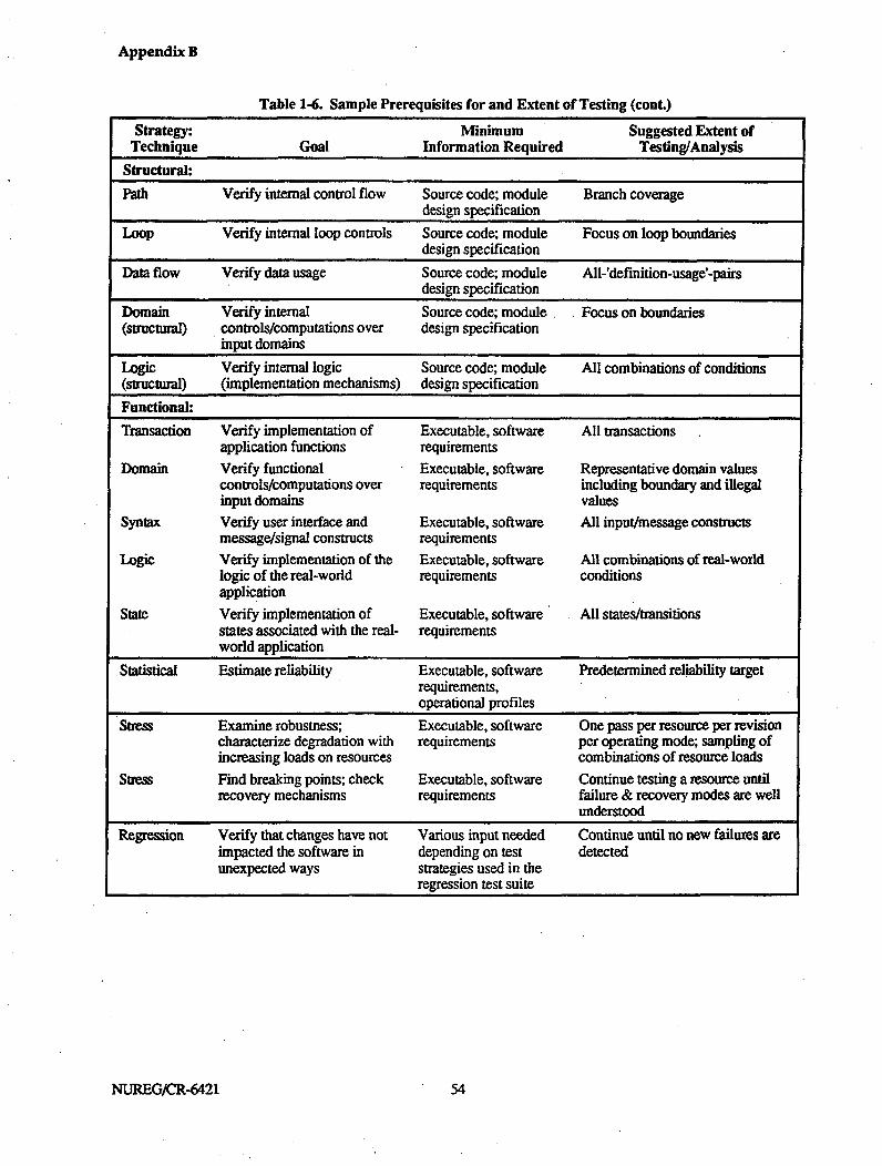
Appendix B
Table 1-6. Sample Prerequisites for and Extent of Testing (cont.)
Strategy: Minimum Suggested Extent ofTechnique Goal Information Required Testing/Analysis
Structural:
Path Verify internal control flow Source code; module Branch coveragedesign specification
Loop Verify internal loop controls Source code; module Focus on loop boundariesdesign specification
Data flow Verify data usage Source code; module All-'definition-usage'-pairsdesign specification
Domain Verify internal Source code; module Focus on boundaries(structural) controls/computations over design specification
input domains
Logic Verify internal logic Source code; module All combinations of conditions(structural) (implementation mechanisms) design specification
Functional:
Transaction Verify implementation of Executable, software All transactionsapplication functions requirements
Domain Verify functional Executable, software Representative domain valuescontrols/computations over requirements including boundary and illegalinput domains values
Syntax Verify user interface and Executable, software All input/message constructsmessage/signal constructs requirements
Logic Verify implementation of the Executable, software All combinations of real-worldlogic of the real-world requirements conditionsapplication
State Verify implementation of Executable, software All states/transitionsstates associated with the real- requirementsworld application
Statistical Estimate reliability Executable, software Predetermined reliability targetrequirements,operational profiles
Stress Examine robustness; Executable, software One pass per resource per revisioncharacterize degradation with requirements per operating mode; sampling ofincreasing loads on resources combinations of resource loads
Stress Find breaking points; check Executable, software Continue testing a resource untilrecovery mechanisms requirements failure & recovery modes are well
understoodRegression Verify that changes have not Various input needed Continue until no new failures are
impacted the software in depending on test detectedunexpected ways strategies used in the
regression test suite
NUREG/CR-6421 54

Appendix B
Table 1-7. Typical Testing Strategies for Investigating Software Qualities
Software Applicable TestingQuality Also see: Question to be Answered Strategies
Acceptability Validity Are real-world events handled properly? Functional (T,D,L,Se)How does the product perform in realistic, Stressheavy load situations?
Accuracy Preciseness Are internal calculations accurate? Structural (DF)Are results accurate? Functional (M)Is there confidence that important calculations Static analysis (I,DC)are accurate?
Availability Reliability Will the software be unavailable due to poor Statisticalreliability?Will functions be available during heavy load Stresssituations?
Clarity Understand- Is the implementation sufficiently clear to a Static analysis (I,DC)ability knowledgeable reviewer?
Completeness Are all requirements expressed in the design? Static analysis (I)Are all design elements implemented in the Static analysis (I)code?Are internals complete? (no missing logic, Static analysis (ASA,1)undefined variables, etc.)Are all aspects of real-world transactions Functional (Mimplemented?Are boundary values and all combinations of Functional (Dj,,Se)conditions accounted for?Are recovery mechanisms implemented? Stress
Correctness Does the product have statically detectable Static analysis (All)faults?Is the implementation/modification structurally Structural (All)correct?Is the implementation/modification functionally Functional (All)correct?Does the product perform correctly in heavy Stressload situations?
Have modifications had unintended effects on Regressionthe behavior of the software?
Integrity Security Are access control schemes appropriate? Static analysis (I)Are access controls and internal protections Structural (All)correctly implemented?Is end-user access management correct? Functional (T)Are access-related boundary values, logic, Functional (D,Sx,L,Se)states, & syntax correctly implemented?
Legend:ASA Automated Structural AnalysisD Domain TestingDC Desk CheckingEF Data Flow Testing
ILLpP
InspectionLogic TestingLoop TestingPath Testing
Se State Testing& Syntax TestingT Transaction Testing
55 NUREG/CR-6421

Appendix B
Table 1-7. Typical Testing Strategies for Investigating Software Qualities (cont.)
Software Applicable TestingQuality Also see: Question to be Answered Strategies
Interface Internal Have interface standards & style been followed? Static analysis (ASAI)Consistency Consistency
Is parameter & variable usage consistent across Static analysis (ASA,I)interfaces?Is transaction data handled consistently among Functional (T)modules?Are boundary conditions treated consistently? Functional (D)Is message syntax consistent? Functional (Sx)Is decision logic consistent among modules? Functional (L)Are system states consistently treated among Functional (Se)modules?
Internal Interface Have standards & style been followed? Static analysis (ASA,I)Consistency Consistency
Is parameter & variable usage consistent? Static analysis (ASA,I)Are conditions handled consistently with respect Structural (P, Lp,D,L)to control flows?Are there inconsistencies in data handling? Structural (DF)(typing, mixed mode, I/O compatibilities, etc.)Are real-world events and logic handled Functional (L, Se)consistently?
Inter- Does the architecture facilitate interoperability? Static analysis (I)operability
Do modules used in transactions exchange & Functional (TD,Se)use information properly?
Performance Is intra-module timing within specification? Structural (PLp)Are transactions performed within required Functional (T)times?Are timing requirements met when boundary Functional (D)values are input?
Is system performance adequate under heavy Stressload conditions?
Preciseness Accuracy Will internal representations yield required Static analysis (DC)precision?Are internal calculations sufficiently exact? Structural (DF)Are real-world transaction results sufficiently Functional MT)exact?
Reliability Availability What is the probability of running without Statisticalfailure for a given amount of time?
Legend:ASA Automated Structral AnalysisD Domain TestingDC Desk CheckingEF Data Flow Testing
NUREG/CR-6421
ILLPP
InspectionLogic TestingLoop TestingPath Testing
Se State TestingSx Syntax TestingT Transaction Testing
56

Appendix B
Table 1.7. Typical Testing Strategies for Investigating Software Qualities (cont.)
Software Applicable TestingQuality Also see: Question to be Answered Strategies
Robustness Has appropriate recovery logic been Static analysis (I)implemented?Are poorly specified/invalid transactions Functional (T,Sx)handled correctly?Are marginal/illegal inputs handled correctly? Functional (D,Sx)Are unexpected combinations of Functional (L,Se)conditions/states handled correctly?Can the system continue operating outside of Samssnormal operating parameters?
Security Integrity Are access controls properly Static analysis (I)designed/implemented?Are access controls consistent with the operating Static analysis (I)environment?Are the structural aspects of access control Structural (All)mechanisms correct?
Security Do access management functions work. Functional (T)(continued) correctly?
Do access management functions work correctly Functional (D,SxL,Se)in the presence of marginal or illegal values andconstructs?
Simplicity Are implementation solutions overly complex? Static analysis (I)Are complexity-related metric values reasonable Static analysis (ASA,I)for a given situation?
Testability How can aspects of the software be tested? Static analysis (DC,I)Understand- Clarity Is the designer/implementer intent clear? Static analysis (DC,I)ability
Does information characterizing the software Static analysis (ASA,I)make sense?
Usability User Can the user correctly form, conduct, & Functional (T,D,Sx)friendliness interpret results of transactions?
Does the user interface design support Static analysis (I)operational procedures?
User Usability Is the user comfortable in forming, conducting, Functional (TSx)friendliness and interpreting results of transactions?Validity Acceptability Are requirements traceable? Static analysis (1)
Are implementation solutions appropriate? Static analysis (DC,I)Is the real world appropriately represented? Functional (All)Is the implementation/modification structurally Structural (All)correct?
Is the implementation/modification functionally Functional (All)correct?
Legend:ASA Automated Structural AnalysisD Domain TestingDC Desk CheckingEF Data Flow Testing
ILLpP
InspectionLogic TestingLoop TestingPath Testing
Se
T
State TestingSyntax TestingTransaction Testing
57 57 NUREG/CR-6421


Appendix B
2. STATIC SOURCE CODE ANALYSIS
2.1. Purpose of Static Source CodeAnalysis
Static source code analysis is the examination of codeby means other than execution, either manual orautomated, with the intent of (1) producing general,metric-related, or statistical information about asoftware object, (2) detecting specific types of faults ina software object, (3) detecting violations of standards,or (4) verifying the correctness of a software object.Static analysis pertains to certain categories of faultsand should be considered complementary to dynamictesting in the overall testing effort. The qualitiesaddressed by static analysis, summarized in Table 1-2,are discussed below.
The section is primarily focused on static source codeanalysis; however, some techniques, such asinspection, have broader applicability. Some of theseextensions are discussed below.
2.2. Benefits and Limitations of StaticSource Code Analysis
Static analysis is code examination without codeexecution. This approach provides a different way ofthinking about fault detection and, therefore, staticanalysis techniques are best applied as part of anoverall testing (or verification and validation) programthat also includes extensive dynamic testing. Theadvent of automated, interactive softwareenvironments and testing tools is blurring thedistinction between dynamic testing and static analysissomewhat. In some of these tools, results are availablefrom static examinations carried out in support ofdynamic, structural testing. The use of interpreters ascode is being examined can automate the deskchecking technique of stepping through lines of codeand, therefore, can produce information about run-timestates (although this information may also be related tothe use of the interpreter).
2.2.1. Benefits
There are a number of f eatures of static analysistechniques that make them an effective complement todynamic techniques. The inspection or review-orientedtechniques have the advantage of combining thedifferent perspectives of the participants and canproduce fault information that may be overlooked by asingle examiner. Inspections have been found to bevery effective in detecting the types of faults that canbe found with static techniques. In addition, manualstatic analysis techniques can easily incorporate
project-specific standards adopted for the applicationof a COTS item to a particular use. Automatedstructural analyzers can perform large numbers ofstatic checks that could not be performed manually,and may detect structural faults that might goundetected in dynamic testing since all possible pathscannot be covered by test cases. Static analysistechniques that provide general information aboutsoftware objects can produce information that will bevaluable in developing test cases for dynamic testing.
Regarding the assessment of software qualities, staticanalysis techniques are effective in examining softwarefor possible faults related to completeness, consistency,and validity. For example, information about thecompleteness of a software item can be gained fromautomated structural analyses that discover missinglogic, unreachable logic, or unused variables.Inspections can provide information about thetraceability of requirements. Both inspections andautomated structural analyses provide a means forevaluating the consistency of application of standardsand style guidelines, as well as for checking parameterand variable usage from a static perspective. Deskchecking can provide information about the accuracyand precision of algorithm implementations.
Static analyses also provide information about othersoftware qualities that may be important to theintended use of a COTS software item, includingtestability, usability, interoperability, clarity,understandability, robustness, and simplicity. Thesetend to be areas where judgment is required makingthe manual techniques particularly effective. Thequalities are addressed with the manual techniques byincluding the appropriate con 'siderations in inspectionchecklists or desk-checking tasks. For example, thenumber of questions about intent raised during aninspection is an indicator of understandability. Inaddition, automated structural analyses can providemetrics and structural information that is useful inassessing these software qualities.
2.2.2. Limitations
Static analysis techniques, in general, do not providemuch information about run-time conditions. Inaddition, many of these techniques are labor-intensiveand, therefore, can be quite expensive to carry out. Incases where there are project-specific considerationsthat need examination by an automated tool, automatedanalyzers must be developed, which is also a costlyendeavor.
59 59 NUREG/CR-6421

Appendix B
2.3. Information Required to PerformStatic Source Code Analysis
As a minimum, the source code must be available. Formost static analysis techniques to be effective, it is alsonecessary to have information on the context (intendedusage), requirements, and design of the software objectbeing examined. To select effective approaches forstatic analysis, it is useful to know what static analysiscapabilities were applied in the developmentenvironment. In particular, most compilers performvarious types of automatic static checking. In manycases, this checking is limited to those checks thatsupport the compiler's primary goal of detectingsyntactic faults before translating statements to objectcode. Compiler results such as syntactic correctness,uninitialized variables, cross reference listings andsimilar matters are a very useful part of static analysis,but should be considered as the first step in staticanalysis, not the totality. Information on the compilerchecks performed is useful in determining the relativeemphasis to place on the various other techniques thatmight be applied.
Since one goal of static source code analysis is todetect violations of standards, it is necessary to haveinformation regarding the standards applied during thedevelopment effort. This information may be difficultto obtain for COTS software; however, someinformation, such as language standards or thecompiler used, should be available. Perhaps a moreimportant application of standards checking is thedevelopment (by the testing or customer organization)of required standards regarding what is acceptable forthe particular COTS software application. Forexample, if certain language constructs are permittedby the language standard but are known to betroublesome in past practice, a safety-criticalapplication might require a local practice standard thatprohibits their use.
2.4. Methods of Performing Static Source.Code Analysis
The static analysis of source code for a software objectmust be planned, designed, created, executed,evaluated, and documented.
2A.4.. Static Analysis Planning and Requirements
The following actions are required to plan and generaterequirements for static analysis of software objects.-
1. Determine the software qualities to be evaluatedwith static techniques. Qualities typicallyexamined in static source code analysis are shownin Table 1-2. For the static analysis of safety -related COTS software, the primary quality ofinterest is correctness, particularly as it is relatedto the qualities of completeness, consistency, and
validity. Other qualities, that may be of interest,depending on the intended role of the COTSsoftware item, can be assessed with static analysis.These incl ude testability, usability,interoperability, clarity, understandability, andsimplicity.
2. Determine which static analysis techniques will berequired. Code inspections and automatedstructural analyzers are recommended as aminimum.
3. Determine what resources will be required in orderto carry out the analyses. Resources includebudget, schedule, personnel, equipment, analysistools, and the platform for automated structuralanalyses.
4. Determine the criteria to be used to decide howmuch static analysis will be required. This is astopping criterion-how much analysis is enough?
5. Determine the software objects to be examined.
2.4.2. Analysis Design and Implementation
The following actions are required to design andimplement static analyses.
1. Create procedures for carrying out the analyses.For techniques such as code inspection, thisinvolves tailoring the technique to the particularproject environment. For other static source codeanalyses, the procedures will specify analyses tobe applied.
2. Prepare for the orderly and controlled applicationof the individual analyses. The followinginformation should be prepared for each analysis:
a Analysis identification. Each analysis musthave a unique identifier.
b. Purpose. Each analysis must have a specificreason for existing. Examples include theapplication of an automated standards auditorto a block of code or the examination of ablock of code to determine whether aparticular error-prone construct has beenused.
c. Input data. The precise data if any, requiredin order to initiate the analysis must bespecified. This should include any parametervalues needed by automated analyzers (thisinformation may also be appropriate as part ofthe procedures).
d. Initial state. In order to reproduce an analysis,the initial state of the automated analyzer mayneed to be specified.
NUREGYCR-6421 660

Appendix B
e, Results. The expected results of the analysismust be known and specified. This couldinclude the absence of a detection of the faultbeing targeted or the specific value range of ametric.
3. Create the platform to support the automatedstructural analyses. This is a mechanism forselecting, executing, evaluating, and recording theresults of analyses carried out by automated staticanalyzers on the software object.7 An automatedstructural analyzer might perform a pre -programmed set of checks or might require inputto select specific checks (as with an interactivetool). Platform components, illustrated in Figure 2-1, include:
a Analysis case selection. A means of selectinganalysis cases (checks) to be executed isrequired. This information may be kept in afile or database, and the selection may simplyconsist of "get next analysis case."
b. Analyzer program. A means of setting theanalyzer's initial state (if necessary),providing input to the analyzer, and recordingthe output from the analyzer is required.
c. Results database. A means of recording theresults for future analysis and evaluation isneeded. Typical data to be captured includethe analysis identifier, date, version ofmodule, analysis output, and an indication ofthe acceptability of the results.
2.43. Execution and Evaluation of the Analywe
The procedures must be carried out and analyzed. If afault is indicated in the software object and thedevelopment organization is performing the analysis,the software engineer is expected to correct the fault.The pattern of test-fix-test-fix continues until alldiscrepancies have been resolved.
In the case of COTS, obtaining corrections may bevery difficult. Suppose the analysis is being performedby (or on behalf of) the customer. If the software wasdeveloped for the customer under contract, thereshould be considerable leverage for obtainingcorrections. If the software is a consumer product (forexample, a library accompanying a compiler used fordevelopment), experience shows that many developershave little interest in expensive repairs that satisfy alimited marketplace. In this case, the options of thecustomer may be simply to reject the software or toevaluate each fault detected and determine, its effects
77eprocess of selecting and initiating analyses and evaluating theresults might be a manual activity; in this case the platform describedis largely conceptual, although the databases should exist and becontrolled.
on safety. If more than one fault exists, the cumulativeeffect of all the faults on safety must also bedetermined.
The nature of the faults encountered must also beconsidered. The discovered faults might be related tonew requirements or standards arising from thespecific, intended application of the COTS product.They might also be minor faults that might haveescaped detection during product development. Inthese cases, the significance of the faults should beevaluated and the options for obtaining correctionsmight be pursued. However, if one or more seriousfaults pertaining to the product itself are discovered,confidence decreases rapidly regarding the suitabilityof the product for use in a safety-related application.
2.5. Discussion of Static Source CodeAnalysis
Static source code analyses, whether done totallymanually or supported by automated techniques, aretypically manpower-intensive processes. Manualprocesses such as inspections require team efforts.Many of the computer-aided methodologies require theinvolvement of the development team, thedevelopment of project-specific tools, or on-line use ofinteractive tools.
It should be noted that, although these techniquesinvolve high manpower costs, static analysistechniques are effective in detecting faults. Onecontrolled experiment (Basili and Selby, 1987) foundthat code reading detected more software faults andhad a higher fault detection rate thani did functional orstructur-al testing. Since static analysis and dynamictesting detect different classes of faults, acomprehensive effort should employ as many staticand dynamic techniques as are practical for the specificproject. The remainder of this section discusses variousstatic analysis techniques.
2.5.1. Inspection
Among the manual techniques, code inspection, peerreviews, and walkthroughs are effective methods forstatically examining code. The techniques areessentially similar in that teams of programmersperform in-depth examinations of the source code;however, code inspections are distinguished by the useof checklists and highly structured teams. One of theimportant benefits common to thes techniques is thatthe different perspectives and backgrounds of theparticipants help uncover problems that the originalsoftware engineer overlooked. All three techniquesbenefit from the participation of development teammembers and probably lose some effectiveness if these
61 61 NUREG/eZR-6421
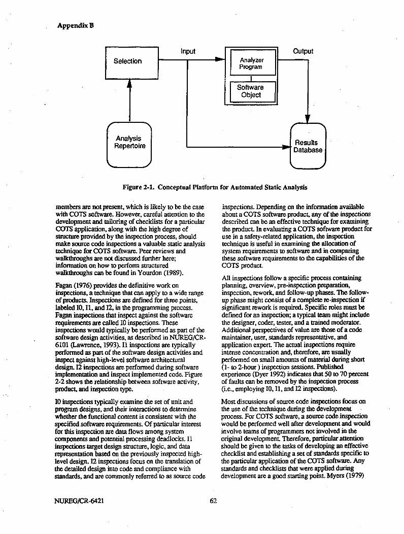
Appendix B
Figure 2-1. Conceptual Platform for Automated Static Analysis
members are not present, which is likely to be the casewith COTS software. However, careful attention to thedevelopment and tailoring of checklists for a particularCOTS application, along with the high degree ofstructure provided by the inspection process, shouldmake source code inspections a valuable static analysistechnique for COTS software. Peer reviews andwalkthroughs are not discussed further here;information on how to perform structuredwalkthroughs can be found in Yourdon (1989).
Fagan (1976) provides the definitive work oninspections, a technique that can apply to a wide rangeof products. Inspections are defined for three points,labeled 10, 11, and 12, in the programming process.Fagan inspections that inspect against the softwarerequirements are called 10 inspections. Theseinspections would typically be performed as part of thesoftware design activities, as described in NURLEG/CR-6101 (Lawrence, 1993). 11 inspections are typicallyperformed as part of the software design activities andinspect against high-level software architecturaldesign. 12 inspections are performed during softwareimplementation and inspect implemented code. Figure2-2 shows the relationship between software activity,product, and inspection type.
10 inspections typically examine the set of unit andprogram designs, and their interactions to determinewhether the functional content is consistent with thespecified software requirements. Of particular interestfor this inspection are data flows among systemcomponents and potential processing deadlocks. 11inspections target design structure, logic, and datarepresentation based on the previously inspected high-level design. 12 inspections focus on the translation ofthe detailed design into code and compliance withstandards, and are commonly referred to as source code
inspections. Depending on the information availableabout a COTS software product, any of the inspectionsdescribed can be an effective technique for examiningthe product. In evaluating a COTS software product foruse in a safety-related application, the inspectiontechnique is useful in examining the allocation ofsystem requirements to software and in comparingthese software requirements to the capabilities of theCOTS product.
All inspections follow a specific process containingplanning, overview, pre-inspection preparation,inspection, rework, and follow-up phases. The follow-up phase might consist of a complete re-inspection ifsignificant rework is required. Specific roles must bedefined for an inspection; a typical team might includethe designer, coder, tester, and a trained moderator.Additional perspectives of value are those of a codemaintainer, user, standards representative, andapplication expert. The actual inspections requireintense concentration and, therefore, are usuallyperformed on small amounts of material during short(I- to 2-hour ) inspection sessions. Publishedexperience (Dyer 1992) indicates that 50 to 70 percentof faults can be removed by the inspection process(i.e., employing 10, I1, and 12 inspections).
Most discussions of source code inspections focus onthe use of the technique during the developmentprocess. For COTS software, a source code inspectionwould be performed well after development and wouldinvolve teams of programmers not involved in theoriginal development. Therefore, particular attentionshould be given to the tasks of developing an effectivechecklist and establishing a set of standards specific tothe particular application of the COTS software. Anystandards and checklists that were applied duringdevelopment are a good starting point. Myers (1979)
NUREG/CR-6421 662

Appendix B
ISoftware Activity
SoftwareRequirements
SoftwareDesign
Implementation
Product Inspection Type
SoftwareRequirementsSpecification
Software Design-Description(Architecture)
Software DesignDescription(Detailed) .
10 inspection
11 inspection
I 12 inspectionCode
Figure 2-2. Software Development Activities, Products, and Inspections
gives a set of typical checklist items grouped by datareference faults, data declaration faults, computationfaults, comparison faults, control flow faults, interfacefaults, and input/output faults. This serves as a startingpoint; the list should then be enhanced by specificknowledge about the product and application inquestion.
The purposes of performing after-the-developmentsource code inspections on COTS software are todetect previously undetected faults, to ensure thatdangerous practices have not been used, to discoverwhether undocumented features are present, and tofocus on anything special pertaining to the use of theCOTS application in a specific environment. Inplanning for static analysis, strategies should bedeveloped for applying techniques efficiently givenproject resources and constraints (subject to therequirements of the commercial dedication process).The entire COTS item should be inspected if possible.If not, the focus should be directed toward keyfunctional areas with some additional randominspections. A powerful practice with any testing orevaluation technique is to attempt to classify detectedfaults or observed failures (such as might have beenseen in other uses of the COTS item) and then to re-examine the code, searching specifically for otherinstances of the fault class.
Establishing standards for a source code inspection of aCOTS item is particularly important. Depending on thecriticality of the particular use of the COTS item, it
may be useful to start with a typical set of standards forthe computer language in question and then to augmentthis set with additional standards based on what isknown about the application in which the COTS itemwill be used. For example, a code unit might have beenproduced according to an established languagestandard. It might also be known that certain legitimateconstructs are prone to errors. For the purposes of theCOTS inspection, taking into account the intended useof the item, a requirement preventing the use of theconstruct might be added to the set of codingstandards. In this case, the particular COTS item mightbe found unsuitable for the particular intended use. Asan alternative, the discovery of the usage of theconstruct might trigger separate static analyses ordynamic tests focused on that area.
2.5.2. Desk Checking
Desk checking is a proven, primarily manual, staticanalysis technique. It typically involves oneprogrammer examining code listings for faults (codereading), checking computations by independentmeans, and stepping through lines of code. To theextent possible, desk checking should not consist ofmanually performed activities that could be automated.For example, an automated standards checker could berun and desk checking could be used to confirm orjustify violations. Desk checking tends to concentrateon special problems or considerations posed by theapplication and involves techniques appropriate tothose problems or considerations. This process can be
63 63 NUREG/CR-6421
Appendix B
aided with the use of interactive debuggers, interactiveanalysis tools, or interactive analysis features ofsoftware development environments. Regardless ofwhich tools are used to aid the process, strategy andprocedures must be developed for the systematicevaluation of the code. In addition to the discovery ofspecific faults, the results obtained in desk checkingshould also be used to help tailor the standards andchecklists used in future source code inspections.
2.5.3. Automated Structural Analysis
Automated structural analysis is the use of anautomated checker to examine source code for faultsoccurring in data and logic structures. An automatedstructural analyzer can be focused to detect specificfaults in dhe code, or can produce general informationabout the code, such as cross-reference maps of.identifiers, calling sequences, and various softwarequality metrics. Information in the general category isuseful as reference data in the inspection and deskchecking analyses discussed above. An automatedstructural analyzer looks for faults such as those listedbelow (Glass 1992):
" Undeclared or improperly declared variables (e.g.,variable typing discrepancies)
* Reference anomalies (e.g., uninitialized orinitialized but unused variables)
" Violations of standards (language and projectstandards)
* Complex or error-prone constructs
" Expression faults (e.g., division by zero)
" Argument checking on module invocations(number of arguments, mismatched types,uninitialized inputs, etc.)
" Inconsistent handling of global data
" Unreachable or missing logic.
Automated structural analyzers are typically language-specific and possibly project-specific. Discussions ofsome of the techniques used by structural analyzers arecontained in Section 3.4 of this report. Price (1992)provides information on static analysis tools. Typicalautomated tools include:
" Code auditors (standards and portability)
* Control structure analyzers (calling graphs, branchand path analysis)
" Cross-reference generators
" Data flow analyzers (variable usage)
* Interface checkers
* Syntax and semantic analyzers
* Complexity measurement analyzers.
An appro ach for performing automated structuralanalysis on COTS software would be as follows:
* Determine which software qualities are to beinvestigated.
* Determine, if possible, what static analysiscapabilities were applied in the development of thecode (e.g., compiler checks).
* Determine what COTS structural analysis tools areavailable for the language used (and particularlanguage standard if more than one exists) by thetarget COTS software.
* Select and apply the appropriate language-specifictools.
* Determine whether there are project-specificconsiderations that should be checked using anautomated structural analyzer.
* Develop and apply the project-specific analyzer (itmay be possible to structure the use of thecapabilities of an interactive analysis tool to get atthese issues).
2.5.4. Other Methods
Various other methods for static source code analysishave been researched. Some are mentioned briefly herebut are not felt to be practical for the static analysis ofCOTS software at this time, either because the methodsare integrated into the development process or becauseextensive development work would be required toimplement the method.
Proof of correctness is a process of applying theorem-proving concepts to a code unit to demonstrateconsistency with its specification. The code is brokeninto segments, assertions are made about the inputs andoutputs for each segment, and it is demonstrated that, ifthe input assertions are true, the code will cause theoutput assertions to be true. Glass (1992) states that themethodology is not yet developed enough to be ofpractical use, estimating that practical value forsignificant programs is about 10 years away.Advantages, if the method is practical, include the useof a formal process, documentation of dependencies,and documentation of state assumptions made duringdesign and coding. Proof of correctness is a complexprocess that could require more effort than thedevelopment itself.
Symbolic evaluation is a technique that allowsvariables to take on symbolic values as well as numeric
NLIREG/CR-6421 664

Appendix B
values (Howden 1981). Code is symbolically executedthrough a program execution system that supportssymbolic evaluation of expressions. Passing symbolicinformation through statements and operatingsymbolically on the information provides insights intowhat a unit is actually doing. This technique requires aprogram execution system that includes symbolicevaluation of expressions and path selection. Oneapplication of this technique would be an attempt todetermine if a formula or algorithm was correctlyimplemented.
Automated structural analyzers are usually based onpre-defined sequences of operations. An extension toautomated structure analyzer capabilities would be todevelop mechanisms whereby user-specifiablesequences could be defined for subsequent analysis.Olender (1990) discusses work to define a sequencingconstraint language for automatic static analysis andpredicts its value when embedded in a flexible,adaptable software environment
65 NUREG/CR-6421


Appendix B
3. STRUCTURAL TESTING
3.1. Purpose of Structural Testing
Structural testing (also known as "white box" or "glassbox" testing) is conducted to evaluate the internalstructure of a software object. The primary concerns ofstructural testing are control flow, data flow, and thedetailed correctness of individual calculations.Structural testing is traditionally applied only tomodules, although extensions to subsystems andsystems are conceivable. It is generally carried out bythe software engineer who created the module, or bysome other person within the developmentorganization. For COTS software, personnel from thedevelopment organization will probably not beavailable; however, structural testing can be carried outby an independent test group. The qualities addressedby structural testing, summarized in Table 1-2, arediscussed below.
3.2. Benefits and Limitations of StructuralTesting
Both the benefits and the limitations of structuraltesting are effects of the concentration on internalmodule structure. Structural testing is the only methodcapable of ensuring that all branches and loops in themodule have been tested. There are important classesof faults that are unlikely to be discovered if structuraltesting is omitted, so no combination of the other testmethods can replace structural testing.
3.2.1. Benefits
Beizer (1990) states that path testing can detect aboutone-third of the faults in a module. Many of the faultsdetected by path testing are unlikely to be detected byother methods. Thus path testing is a necessary but notsufficient component of structural testing. Acombination of path and loop testing can uncover 50 to60% of the intra-modular faults. Adding data flowtesting results, on average, in finding nearly 90% ofintra-module faults. (It is assumed here that a thoroughtesting effort is performed with respect to eachtechnique.) Some modules, of course, are worse thanaverage, and the remaining faults are likely to beparticularly subtle.
Structural testing is focused on examining thecorrectness of the internals of a module, i.e., on faultsrelating to the manner in which the module wasimplemented. This includes faults related to accuracy,precision, and internal consistency. Control flow faultsbased on inconsistent handling of conditions can befound, as well as data inconsistencies related to typing,
file I/O, and construction of expressions. Someinformation, such as algorithm timing, can be gainedregarding software performance. Finally, emphasis ontesting proper referencing and data handling as well ason the implementation of access controls providesinformation about integrity and security.
3.2.2. Limitations
Structural testing is impossible if the source codesis notavailable. The modules must be well understood fortest cases to be designed and for correct results of thetest cases to be predictable. Even moderately largecollections of well-designed modules benefit from theassistance of reverse engineering tools, test generators,and test coverage analysis tools. Generating anadequate set of structural test cases is likely to be quitetime-consuming and expensive.
Structural testing is almost always restricted to testingmodules. Given further research, it might be possibleto extend structural testing to subsystems and systems,which would be useful for a distributed control system(DCS). Here, the analogy to the flow of control amongthe statements of a module is the flow of control thattakes place as messages are passed among theprocesses making up the DCS. When concurrentcommunicating processes are executing on a networkof different computers, subtle errors involving timingcan occur, and structural testing might be extended tohelp detect these.
3.3. Information Required to PerformStructural Testing
Structural testing requires detailed knowledge of thepurpose and internal structure of the module: modulespecification (including inputs, outputs and function),module design, and the source code.
A test station is recommended. This station would havethe ability to select pre-defined test cases, apply thetest cases to the module, and evaluate the results of thetest against pre-defined criteria.
3.4. Methods of Performing StructuralTestingThe structural test must be planned, designed, created,executed, evaluated, and documented.
3.4.1. Test Planning and Test Requirements
The following actions are required to plan and generaterequirements for structural testing.
67 NUREG/CR-6421
Appendix B
1. Determine the software qualities that are beingevaluated. For the structural testing of safety -related COTS software, the primary quality ofinterest is correctness, particularly in the sense ofaccuracy, precision, robustness, and internalconsistency.
2. Determine which structural testing techniques willbe required. Control flow (path) and data flowtesting are the minimum requirements. Additionaltechniques may be required in some cases.
3. Determine what resources will be required in orderto carry out the testing. Resources include budget,schedule, personnel, equipment, test tools, teststation, and test data.
4. Determine the criteria to be used to decide howmuch testing will be required. This is a stoppingcriterion-how much testing is enough? Forexample, "95% of all paths in the module shall becovered by control flow testing."
5. Determine which modules will be tested.
3.4.2. Test Design and Test Implementation
The following actions are required to design andimplement structural testing.
1. Create procedures for executing the structural testcases. This is typically done within the contextcreated by test plan and test design documents(IEEE 829). Additional guidance for the testingprocess for modules is given in IEEE 1008.
2. Create individual test cases. Each test case shouldcontain the following information:a. Test identifi cation. Each test case must have a
unique identifier.
b. Purpose. Each test case should have a specificreason for existing. Examples includeexecuting a specific path through the module,manipulating a specific data object, orchecking for a specific type of fault. For thelatter, see headings 3 and 4 of the BugTaxonomy in the Annex.
c. Input data. The precise data required in orderto initiate the test must be specified.
d. Initial state. In order to reproduce a test case,the initial state of the module (before the testbegins) may need to be specified. Thisinformation is not necessary if the module isintended to execute correctly and identicallyin all initial states. For example, a square rootmodule should return the square root of theinput value no matter what has gone before.
ea Test results. The expected results of the testmust be known and specified. These caninclude values of data objects external to themodule (such as actuator values and databasevalues) and values of output parametersreturned through the module calling interface.
f Final state. In some cases, the final state ofthe module must be specified as part of thetest case information. This can occur, forexample, if the final state after a call is usedto modify the execution of the module thenext time it is called.
3. Create the test station. This is a mechanism forselecting, executing, evaluating, and recording theresults of tests carried out on the module. Teststation components, illustrated in Figure 3-1,include:a Test case selection. A means of selecting test
cases to be executed. Test case information istypically kept in a file or database, and theselection may simply consist of "get next testcase."
b. Test program. A means of setting themodule's initial state (if necessary), providinginput to the module, recording the outputfrom the module and (if necessary) recordingthe final state of the module.
c. Test oracle. A means of determining thecorrectness of the actual output and modulestate.
d. Results database. A means of recording thetest results- for future analysis and evaluation.Typical data are: test identifier, date, versionof module being tested, test output and state,and an indication of correctness or failure ofthe test.
3.4.3. Test Execution and Test Evaluation
The test procedures must be carried out and the resultsanalyzed. If discrepancies between the actual andexpected results occur, there are two possibilities:either the test case has a fault or the module has a fault.In the first case, the test case should be corrected andthe entire test procedure rerun.
If the module has a fault and the developmentorganization is performing the test, the programmer isexpected to correct the fault. The pattern of test-fix-test-fix continues until all discrepancies have beenresolved.
NUREG/CR-6421 668
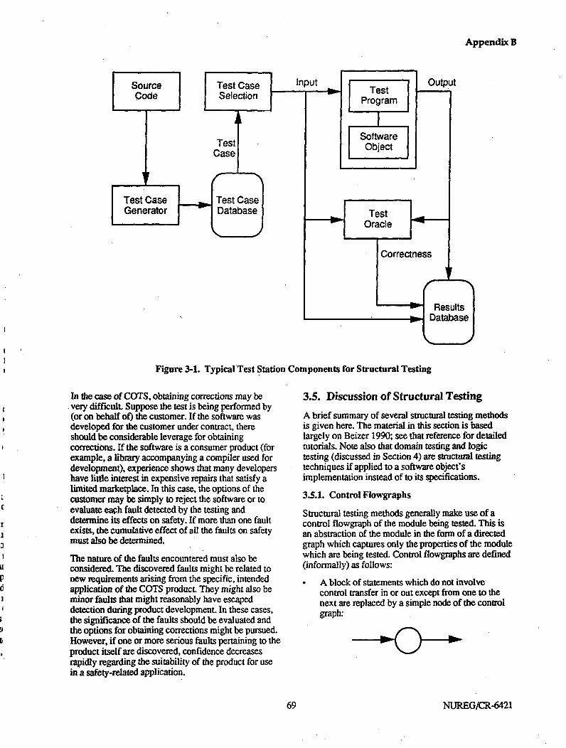
Appendix B
Figure 3-1. TypicalTest Station Components for Structural Testing
In the case of COTS, obtaining corrections may bevery difficult. Suppose the test is being performed by(or on behalf of) the customer. If the software wasdeveloped for the customer under contract, thereshould be considerable leverage for obtainingcorrections. If the software is a consumer product (forexample, a library accompanying a compiler used fordevelopment), experience shows that many developershave little interest in expensive repairs that satisfy alimited marketplace. In this case, the options of thecustomer may be simply to reject the software or toevaluate each fault detected by the testing anddetermine its effects on safety. If more than one faultexists, the cumulative effect of all the faults on safetymust also be determined.
The nature of the faults encountered must also beconsidered. The discovered faults might be related tonew requirements arising from the specific, intendedapplication of the COTS product. They might also beminor faults that might reasonably have escapeddetection during product development. In these cases,the significance of the faults should be evaluated andthe options for obtaining corrections might be pursued.However, if one or more serious faults pertaining to theproduct itself are discovered, confidence decreasesrapidly regarding the suitability of the product for usein a safety-related application.
3.5. Discussion of Structural Testing
A brief summary of several structural testing methodsis given here. The material in this section is basedlargely on Beizer 1990; see that reference for detailedtutorials. Note also that domain testing and logictesting (discussed in Section 4) are structural testingtechniques if applied to a software object'simplementation instead of to its specifications.
3.5.1. Control Flowgraphs
Structural testing methods generally make use of acontrol flowgraph of the module being tested. This isan abstraction of the module in the form of a directedgraph which captures only the properties of the modulewhich are being tested. Control flowgraphs are defined(informally) as follows:
A block of statements which do not involvecontrol transfer in or out except from one to thenext are replaced by a simple node of the controlgraph:
69 NUREG/CR-6421

Appendix B
Figure 3-6. Control Flowgraph Augmented to Show Data Flow
NUREG/CR-6421 774

Appendix B
4. FUNCTIONAL TESTING
4.1. Purpose of Functional Testing
Functional testing (also known as "black box" testing)consists of testing the functions to be performed by asoftware element as defined in requirements, designspecifications and user documentation. It is focused oncomparing actual and specified behavior, independentof the structural characteristics of the software. Theprimary concerns are functional and timingrequirements. Programs, subsystems and systems aretested in large part with functional tests, however,functional tests also apply to packages and modules.Although, structural testing and static analyses are thedominant testing strategies for at these levels, thedesign specifications for packages and modules shouldcontain information on which to base functional tests.This is particularly true for software elements such ascommunications packages, device drivers, andmathematical subroutines. For COTS software,functional testing is likely to be applied to programs,subsystems and systems, and will normally be carriedout by or on behalf of the customer. The qualitiesaddressed by functional testing, summarized in Table1-2, are discussed below.
4.2. Benefits and Limitations of FunctionalTesting
Both the benefits and limitations of functional testingare a result of the fact that the execution of functions isexamined rather than the internal structure of thesoftware object. The focus is on verifying thatrequirements and user needs have been met. Functionaltesting can be applied at any level but is usuallyassociated with programs, subsystems, and systems.
4.2.1. Benefits
Since the focus is not on internal software structure, itis easier for functional testing to be performed byindependent parties. Test cases may originate with thecustomer, user, or regulator. For COTS software, testcases might also originate from information gatheredfrom the experience of other users of the item. Finally,functional testing techniques do not require theavailability of source code, which, for COTS software,may not be available.
Functional testing techniques can address a wide rangeof software qualities. Test cases for functional testingtechniques address technical correctness by allowingverification of the accuracy and precision of results aswell as verification of the consistency, interoperability,and performance of the software item. Consistency and
interoperability are addressed by examining theinteractions among modules as transactions areprocessed. Performance is addressed via test casesfocused on timing requirements for real-worldtransactions. Regarding the correctness of a softwareitem in the sense of its being complete, acceptable, andvalid, test cases can focus on missing or partiallyimplemented transactions, improper handling of real -world conditions and. states, and incorrectrepresentations of user needs and the real-worldenvironment. Functional test cases can also bedesigned to test security and integrity mechanisms,user interfaces, and robustness in the presence ofinvalid inputs.
4.2.2. Limitations
Functional testing usually does not detectundocumented features or functions such asdevelopment aids left in the software. Since testershave no visibility into internals, functional subtletiesmay be overlooked, particularly if structural testing hasnot been performed.
4.3. Information Required to PerformFunctional Testing
Functional testing requires a software requirementsspecification, user instructions, detailed knowledge ofexternal interfaces (to sensors, actuators, operators, andother software), and the software object being tested.
A test station is recommended for testing by customers.This includes the ability to select pre-defined testcases, apply the test cases to the software object, andevaluate the results of the test against pre-definedcriteria. The ability to reproduce functional testing willgenerally be necessary, and a test station is the mosteffective tool to accomplish this.
4.4. Methods of Performing FunctionalTesting
The functional testing must be planned, designed,created, executed, evaluated, and documented.
4.4.1. Test Planning and Test Requirements
The following actions are required to plan and generaterequirements for functional testing.
1. Determine the software qualities that are beingevaluated. For safety-related COTS software, theprimary quality of interest is correctness. In atechnical sense, this encompasses accuracy,
75 75 NUREG/CR-6421

Appendix B
precision, consistency, interoperability, andperformance. From a product perspective,correctness includes acceptability, completeness,and validity. Other qualities that can be addressedare integrity, security, robustness, usability, anduser friendliness.
2. Determine which functional testing techniqueswill be required. Transaction testing and domaintesting are minimal requirements. Additionaltechniques should be employed if the goal of thetechnique is applicable to the software object.
3. Determine what resources will be required in orderto carry out the testing. Resources include budget,schedule, personnel, equipment, test tools, teststation, and test data.
4. Determine the criteria to be used to decide howmuch testing will be required. This is a stoppingcriterion-how much testing is enough?
5. Determine which software objects will be tested.
4.4.2. Test Design and Test Implementation
The following actions are required to design andimplement functional testing.
1. Create procedures for executing the functional test-cases.
2. Create individual test cases. Each test case shouldcontain the following information:a. Test identification. Each test case must have a
unique identifier.
b. Purpose. Each test case should have a spe cificreason for existing. Examples includeverifying that a particular timing constraintcan be met, that a particular function isperformed correctly, or checking for aspecific type of failure. For the latter, seeheadings 1 and 2 of the Bug Taxonomy in theAnnex.
c. Input data. The precise data required in orderto initiate the test must be specified.
d. Initial state. In order to reproduce a test case,the initial state of the software object (beforethe test begins) may need to be specified. Thisinformation is not necessary if the object isintended to execute correctly and identicallyin all initial states. For example, a transactionprocessing program should correctly handleany transaction no matter what has gonebefore.
e. Test results. The expected results of the testmust be known and specified. These are the
values of data objects external to the softwareobject under test (such as actuator values,display screen values, and database values).
f Final state. In some cases, the final state ofthe object must be specified as part of the testcase information.
3. Create the test station. This is a mechanism forselecting, executing, evaluating, and recording theresults of tests carried out on the object. Teststation components, illustrated in Figure 4-1,include:a Test case selection. A means of selecting test
cases to be executed. Test case information istypically kept in a file or database, and theselection may simply consist of "get next testcase."
b. Test program. A means of setting the object'sinitial state (if necessary), providing input tothe object, recording the output from theobject, and (if necessary) recording the finalstate of the object.
a. Test oracle. A means of determining thecorrectness of the actual test output and objectstate.
d. Results database. A means of recording thetest results for future analysis and evaluation.Typical data include the test identifier, date,version of object being tested, test output andstate, and an indication of correctness orfailure of the test.
4.43. Test Execution and Test Evaluation
The test procedures must be carried out and the resultsanalyzed. If discrepancies between actual and expectedresults occur, there are two possibilities: either the testcase has a fault or the object has a fault. In the firstcase, the test case should be corrected and the entire*test procedure rerun.
If the object has a fault and the developmentorganization is performing the test, the programmer isexpected to correct the fault. The pattern of test-fix-test-fix continues until all discrepancies have beenresolved.
In the case of COTS software, obtaining correctionsmay be very difficult. Suppose the test is beingperformed by (or on behalf of) the customer. If thesoftware was developed for the customer undercontract, there may be considerable leverage for,obtaining corrections. If the software is a consumerproduct (for example, a library accompanying a
NTJREG/CR-6421 776

Appendix B
Figure 4-1. Typical Test Station Components for Functional Testing
compiler used for development), experience shows thatmany developers have little interest in expensiverepairs that satisfy a limited marketplace. In this case,the options of the customer may be simply to reject thesoftware or to evaluate each fault detected by thetesting and determine its effects on safety. If more thanone fault exists, the cumulative effect of all the faultson safety must also be determined.
The nature of the faults encountered must also beconsidered. The discovered faults might be related tonew requirements arising from the specific, intendedapplication of the COTS product. They might also beminor faults that might reasonably have escapeddetection during product development. In these cases,the significance of the faults should be evaluated andthe options for obtaining corrections might be pursued.However, if one or more serious faults pertaining to theproduct itself are discovered, confidence decreasesrapidly regarding the suitability of the product for usein a safety-related application.
4.5. Discussion of Functional Testing
There are a number of techniques for developingfunctional tests. A summary of several of these is givenbelow and is based largely on Beizer (1990); see thatreference and Howden (1987) for detailed information.
4.5.1. Transaction Testing
A transaction is a complete unit of work as seen by theoperators of the computer system. An example ischanging the value of a set point. The operatornormally views this as a simple action--entering avalue on a display screen causes the value to change,resulting in a change to some other portion of thescreen. In fact, many processes may be invoked onmultiple computers to carry out the action, but none ofthe details are of interest to the operator.
Transaction testing is similar to control flow testing(Section 3.4.2) in that it is based on a flowgraph. Itdiffers from control flow testing in that the flows intransaction testing are derived from the requirementsspecification, while the flows in control flow-testingare derived from the program internal structure.Transaction testing is carried out at the program,subsystem, or system level instead of the module level.Nodes on the flowgraph represent processes that act onthe transaction, while the links on the graph representthe movement of transaction data from one process toanother. Note that a transaction flowgraph does notnecessarily match program control flow. An example isshown in Figure 4-2.
77 NUREG/CR-6421

Appendix B
Figure 4-2. Example of a Transaction Flowgraph
Transactions typically are born (created) as a result ofsome triggering action, exist for some period of time,and then die. Each transaction can be modeled by atransaction flowgraph, and there is a separate graph foreach transaction. Some computer systems involvehundreds of transactions, resulting in a large supply ofgraphs. Alternative flows on the graph may exist tohandle errors and peculiar conditions. Transactionsmay "spawn" additional transactions, and multipletransactions may collapse into a single one. Theresulting flow can be quite complex.
Transaction testing assumes that the processing withineach node of the flowgraph is correct, but that theremay be errors in routing transactions from one node toanother. A test must be created for every path fromtransaction birth to transaction death. Particularattention must be devoted to paths caused by errors,anomalous data or timing, or other strange events.
4.S.2. Domain Testing
A progrmi can frequently be viewed as a functiontransforming input values to output values. Programsgenerally operate on more than one input variable, andeach adds a dimension to the input space. Thecollection of all input variables determines a vector,known as the input vector. An example might be
(temperature, pressure, ne utron flux, on/off switch,valve position)
where the first three are assumed to be read fromsensors and the last two read from an operator console.Domain testing divides the input vector values intosets, called domains, where the program behaves thesame for all values in the set.
An example of a specification for a control functionbased on a single variable, temperature, might take thefollowing form (the errors are deliberately included forillustrative purposes):
if temp < 0if 0 < temp < 50if 50•5 temp < 80if 75 < temp < 150
if 150 < temp
errorturn on heaterturn off both heater and cooler
turn on cooler (this is assumedto be a specification error, i~e.,assume the requirements callfor shutdown at 120)
emergency shutdown (this isassumed to be a specificationerror, i.e., assume therequirements call for shutdownat 120)
In this example (illustrated in Figure 4.3), there arefive domains, with boundaries at 0, 50, 80, and 120.The boundaries are typically points in the input spaceat which a new rule applies. The calculations areassumed to be correct for all values in each set, andfaults are sought at or near the boundaries of thedomain. Several errors are shown in the example:
* It is not known how the program should respondfor temp = 0 and temp = 150.
*There are inconsistent requirements for 75 < temp< 80 since the domains overlap.
* The problem statement requires (it is assumedhere) emergency shutdown at 120, not 150.
NLJREG/CR-642l 778

Appendix B
Figure 4-3. Example of Domains
Domains can be drawn and analyzed manually for oneor two variables. Real-time control system softwaregenerally requires more than two sensors and operatorsignals, so the application of domain testing can beimpractical unless automated tools can be found. 11
Test cases for domain testing are concentrated at orvery near the boundaries of each domain. Figure 4-4shows hypothetical two-dimensional input spaces,where the shaded areas represent anticipated inputvalues. The asterisks show a few of the possible testinput values. If test cases are based on codeimplementation rather than specifications, domaintesting is considered to be a structural technique.
Howden,(1981) points out that techniques forexamining classes of input data can also be applied tothe, examination of classes of output data. In caseswhere classes of output data are related to classes ofinput data, selecting input data to produce output at theboundaries of the output classes can yield usefulresults. In addition, it is also useful to consider invalidoutput data and to attempt to generate this output withselected inputs. This approach is closely related to theuse of fault tree analysis.
4-5.3. Syntax Testing
The syntax of external inputs, such as operator orsensor inputs, and internal inputs, such as data crossinginterfaces between subsystems, must be validated. Inaddition to the well-documented input syntax that maybe described in the requirements and design
IIA reviewer pointed out that he was unaware of the use of domaintesting in real-time systems.
specifications, it is also necessary to examine thesoftware object for implicit, undeclared languages.These may be found in areas such as user and operatorcommand sets, decision logic relating to transactionflows, and communications protocols. Sources for thisinformation include requirements and designdocumentation, manuals, help screens, and developerinterviews. Items relating to hidden languages shouldbe included on code inspection checklists (see Section2). For defined or hidden languages, the syntax must bedefined with a tool such as BNF and a set of syntaxgraphs must be created on which to base test cases forvarious syntactic constructions. Figure 4-5 shows atrivial example of a syntax graph. A sentence would beformed based on the syntax graph by following a pathindicated by the arrows, making legitimatesubstitutions when rectangles are encountered, andinserting literally the contents of the circles. Thus,PAUSE; and PAUSE [{5); would be legitimateconstructions.
Testing consists of supplying a combination of validand invalid constructions as inputs. Types of faultsdiscovered with syntax testing relate to cases wherevalid constructions are not accepted, invalidconstructions are accepted, or where the handlingmechanisms for valid or invalid inputs break down.Beizer (1990) notes that the invalid constructions leadto the biggest payoffs in this type of testing. Fairlysimple syntax rules can lead to very large numbers ofpossible test cases, so automated means must be usedto accomplish the testing.
79 79 NUREG/CR-6421

Appendix B
Figure 4-4. Examples of Two-Dimensional Domains with Examples of Test Values
Figure 4-5. Example of a Syntax Graph
4.5.4. Logic-Based Testing
Some applications or implementations must deal withsituations in which the values of a number ofconditions must be evaluated and appropriate actionstaken depending on the particular mix of conditionvalues. If these situations are derived from systemrequirements, they are functional issues; if they are theresult of the design approach, they are structural issues.Functional logic-based testing consists of testing thesoftware system's logic for handling these mixes ofconditions. In addition to the correctness of the logic,software quality factors of completeness and internalconsistency are also addressed.
Decision tables can be an effective means fordesigning test cases to examine software logic. Thislogic might be explicitly documented using techniquessuch as decision tables or decision trees, or might beimplicit in the software requirements or designspecifications. In the latter case, the sources forobtaining information are the same as for syntaxtesting. The cause--effect graphing technique can beapplied to transform this information into decision
table format; an example is provided in Pressman(1987).
An example of a limited entry (conditions and actionsare binary valued) decision table is shown in Figure 4-6. A detailed discussion of decision tables can be foundin Hurley (1983). A rule consists of the actions to befollowed when the specified conditions hold. Note thatthe rule corresponding to conditions (Y,Y,Y) ismissing, possibly corresponding to an impossiblephysical situation. The dash in rule 4 means that thevalue of condition 3 is immaterial for this rule (i.e.,rule 4 represents two cases, N,Y,Y and N,Y,N).
Testing based on this decision table should begin witha verifying the completeness and consistency of thetable (see Hurley, 1983). Then test cases should bedeveloped to ensure that the software performs thecorrect actions for the specified rules. It should beverified, by attempting to design a test case, that a(Y,Y,Y) situation is indeed impossible, and bothoptions for rule 4 should be tested to ensure that thesame action is taken.
NUREG/CR-6421 80

Appendix B
RULES1 2 3 4 5 6
Conditioni1 Y Y Y N N NCondition 2 Y N N Y N NCondition 3 N Y N - Y N
Actioni1 XAction 2 X X XAction 3 X XAction 4 X X X X
Figure 4-6. Example of a Decision Table
The use of a decision table model for designing tests isappropriate when the following requirements hold(Beizer 1990):
" The specification consists of, or is amenable to, adecision table.
" Thbe order of condition evaluation does not affectrule interpretation or resulting actions.
" The order of rule evaluation does not affectresulting actions.
" Once a rule is satisfied, no other rule need beconsidered.
" If multiple actions can result from a given rule, theorder in which the actions are executed does notmatter.
4.5.5. State Testing
Testing based on state-transition models is effective inexamining a number of areas including communicationprotocols, failure and recovery sequences, andconcurrent processing. Figure 4-7 illustrates a statetransition diagram with three states indicated by boxesand three transitions indicated by arrows. The triggerfor the state change (input or event) is shown in the toppart of the transition label and the action or outputassociated with the transition is shown in the bottompart of the label. (Note that state-transition models canbe depicted with other notation, such as state tables.)For each input to a state, there must be exactly onetransition specified; if the state doesn't change, atransition is shown to and from the same state.
Faults can be associated with an incorrect structure fora state-transition model or with a structurally correctmodel that does not accurately represent the modeledphenomena. In the former category, faults can berelated to conditions such as states that cannot bereached or exited or the failure to specify exactly onetransition for each input.- These types of faults can bedetected from a structural analysis of the model. In thelatter category, faults can be related to conditions suchas states missing from the model, errors in thespecification of triggering events, or incorrecttransitions. Detection of these errors involves theanalysis of, or testing against, specifications. Missingstates can arise from incorrect developer assumptionsabout possible system states or real world events.Errors in modeling triggering events or associatedoutputs can easily arise from ambiguities contained insystem or software requirements. For embedded COTSsoftware, states of the software itself or states related tothe interface of the software to the larger system mayneed to be modeled as a basis for analysis and testing.
To perform state testing, it is first necessary to developcorrect state-transition diagrams for the phenomenabeing investigated. An analysis should be made toverify that the state-tansition model is consistent withthe design and that the model to be used is structurallycorrect. Design errors might be indicated by thisanalysis. Following this analysis, a set of test casesshould be developed that, as a minimum, covers allnodes and links of the diagrams. Test cases shouldspecify input sequences, transitions and next states, andoutput sequences.
81 81 NUREG/CR-6421
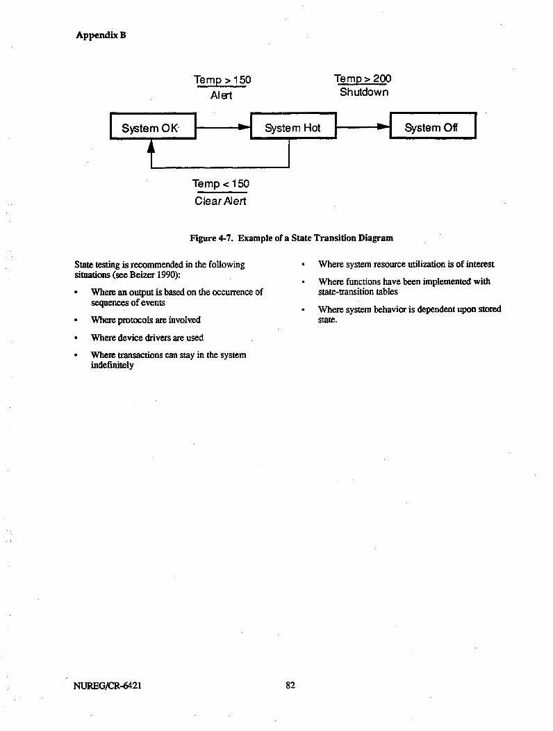
Appendix B
Temp >150Alert
Temp > 200Shutdown
Temp < 150
Clear Aiert
Figure 4-7. Example of a State Transition Diagram
State testing is recommended in the followingsituations (see Beizer 1990):" Where an output is based on the occurrence of
sequences of events
" Where protocols are involved
" Where device drivers are used
" Where transactions can stay in the systemindefinitely
Where system resource utilization is of interest
Where functions have been implemented withstate-transition tables
Where system behavior is dependent upon storedstate.
NUREG/CR-6421 882

Appendix B
5. STATISTICAL TESTING
5.1. Purpose of Statistical Testing
Statistical testing is conducted to measure thereliability of a software object or to predict itsprobability of failure, rather than to discover softwarefaults. It consists of randomly choosing a sample ofinput values for the software object and thendetermining the correctness of the outputs generatedfrom those inputs. Obtaining a statistically validreliability measure using this testing strategy requiresthat the following assumptions hold:
1. The test runs are independent.
2. For each input, the chance of failure is constant.That is, the probability of failure is independent ofthe order in which samples are presented to thesoftware object, and of the number of samples thatprecede the specific input.
3. The number of test runs is large.
4. All failures during testing are detected.
5. The distribution of the inputs under real operatingconditions is known.
The qualities addressed by statistical testing areavailability and reliability.
It is possible to use statistical testing for the goal offinding failures (random testing). That is, one runsrandomly selected tests in the hopes of finding failures.This is likely to be less efficient than the other, moredirected, forms of testing. Of course, if failures dohappen during statistical testing, the faults should befound and corrected. See Hamlet (1994) for adiscussion of random testing.
5.2. Benefits and Limitations of StatisticalTesting
5.2.1. Benefits
Statistical testing does not rely on any knowledge ofthe internal composition of the software object, so itcan be carried out whether or not such knowledgeexists. It is the only way to provide assurance that aspecified reliability level has been achieved. Statisticaltesting (as discussed here) is less prone to human biaserrors than other forms of testing. It is a practicalmethod in many cases when moderate-to-highreliability (in the range of 1 04A to 10O- failures perdemand) is required.
Statistical testing addresses the reliability quality byestimating probabilities based on large numbers oftests. Reliability information also provides informationregarding potential availability, although it does notaddress external factors, such as system loads oradministrative procedures, that may affect accessibilitywhen a particular capability is needed.
5.2.2. Limitations
A number of practical issues with statistical testinglimit its usefulness in some instances. The first set ofissues relates to the test planning and test station (seebelow). The most difficult of these issues arefrequently the construction and verification of the testoracle. Determining the operational profile may benearly as difficult.
The second set of issues involves the length of timenecessary for testing. Testing to the level of reliabilityrequired for a typical safety-critical process controlsystem should be feasible, but testing to much higherlevels of reliability is not. (See the discussion ofexpected test duration in section 5.4.2.)
The third set of issues concerns the relationshipbetween safety and reliability. Statistical testingprovides *a reliability number, not a safety number.Since inputs with safety implications should be a verysmall percentage of all possible inputs, it is not likelythat random testing will include many safety-criticalinput cases. In such cases, it may be possible to carryout two series of tests: one based on all possible inputcases, and one based only on safety-critical input cases.This would result in two numbers--an overallreliability figure and a safety-related reliability figure.The latter could be reasonably termed a safetyreliability number. This approach does, however,require that the set of safety-critical input events becompletely understood so that the safety-critical inputspace can be completely and accurately characterized.This may be difficult to accomplish.
5.3. Information Required to PerformStatistical Testing
Statistical testing requires no knowledge of the internalcomposition or structure of the software object beingtested. It does require a good understanding of 'thestatistical distribution of inputs which can be expectedto appear during actual operating conditions (theoperational profile). A test platform is required, whichincludes the ability to generate random tests using theoperational profile, the ability to carry out each test onthe software object, and the ability to evaluate the
83 83 NUREGJCR-6421

Appendix B
results for correctness. Since many thousands of testsare required in order to obtain a valid reliabilitynumber, the test platform must be automated.
5.4. Methods of Performing StatisticalTesting
The statistical test must be planned, designed,implemented, executed, evaluated, and documented.The following steps (or their equivalent) must becarried out,
5.4.1. Test Planning and Test Requirements
The following actions are required to plan and generaterequirements for statistical testing. Statistical testingfocuses on the reliability quality of software. Forsafety-related COTS software, the goal of statisticaltesting is to provide a measure of the item's reliabilitygiven its anticipated operational profile (i.e., given thespecific role that the COTS item will play in the safety -related system). Thbe software qualities of interest forstatistical testing are reliability and availability.
1. Determine the level of reliability to be achieved.This is generally given in terms of the maximumacceptable failure rate-for example, that thefailure rate cannot exceed 10-5 per demand.
2. Determine if faiures will be tolerated. A statisticaltest will be carried out for some period of time,recording all failures. At some point, the numberof failures may be so large that the test will bestopped and the software object rejected. If the testis to be statistically valid, this point must bedetermined during test planning. For reactorprotection systems, the objective should be tocarry out the test without failure. In this case, anyfailure will cause the test to stop, the fault to becorrected, and the test to be completely rerun.When a statistical test is re-run, it is crucial thatthe random numbers selected be independent ofsequences previously used.
3. Determine the degree of statistical confidencewhich will be required in the test results. This willbe given as a percentage-for example, .99.
4. Determine what resources will be required in orderto carry out the testing. Resources include budget,schedule, personnel, equipment, test tools, teststation, and test data.
5. Determine which software objects will be tested.
5A.42. Test Design and Test Implementation
The following actions are required to design andimplement statistical testing.
1. Calculate the number of test cases which must becarried out without failure to achieve the specifiedreliability with the specified confidence level.
The number of test cases, n, is given by the followingformula, where f is the failure rate and C is theconfidence level (Poore, Mills, and Mutchler 1993):
[Ioga - c)1log(1-f7)
Table 5-1 shows approximate values of n for variousvalues of c and f . In this table, WM stands forI'million.' This table shows that increasing the requiredlevel of confidence in the test results can be obtainedwith relatively little extra effort. However increasingthe required level of reliability (decreasing the failurerate) that must be demonstrated requires considerablymore test cases to be executed and consequentlyincreases test time.
Given a required number of test cases and anassumption about the average number of test cases thatcan be carried out per unit time, estimates can be madeof the total time that will be required for test execution.Table 5-2 shows the approximate amount of executiontime required to achieve specified failure rates at the.99 confidence level under two assumptions of the rateof testing: one test per second and one test per minute.In the first case, testing is impractical for failure ratesunder 10-7; in the latter, under 10-5. Note that this tableassumes that tests are carried out 24 hours per day,seven days per week, and that no failures areencountered during the test. Determining the expectedamount of calendar (elapsed) time for the test will belonger if the assumptions are not valid. The timesgiven in the table are examples; if test cases requiremore (or less) time, then the table can be adjusted. Forexample, if a test case requires five minutes to execute,then nearly six years will be required for a failure rateof 05
NUREG/CR-6421 884
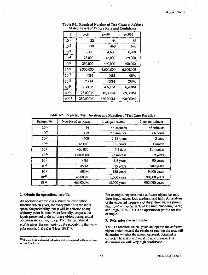
Appendix B
Table 5-1. Required Number of Test Cases to AchieveStated Levels of Failure Rate and Confidence
f c=.9 c=.99 c=.999
10-1 22 44 6610-2 230 460 69010-3 2,300 4,600 6,900
10-4 23,000 46,000 69,000
10.5 230,000 460,000 690,000
10-6 2,300,000 4,600,000 6,900,00010-7 23M 46M 69M10-8 230M 460M 690M
10-9 2,300M 4,600M 6,900M
10-10 23,000M 46,00GM 69,000M10-11 230,000M 460,00GM 690,000M
Table 5-2. Expected Test Duration as a Function of Test Case Duration
Failure rate Number of test cases 1 test per second 1 test per minute
10-1 44 44 seconds 45 minutes10-2 459 7.5 minutes 7.6 hours10"3 4600 1.25 hours 3 days10-4 46,000 13 hours 1 month
10-5 460,000 5.5 days 11 months10-6 4,600,000 1.75 months 9 years10-7 46M 1.5 years 90 years
108 460M 15 years 900 years10-9 4,600M 150 years 9,000 years
10"10 46,000M 1,500 years 90,000 years10-11 460,00GM 15,000 years 900,000 years
2. Obtain the operational profile.
An operational profile is a statistical distributionfunction which gives, for every point p in the inputspace, the probability that p will be selected at anyarbitrary point in time. More formally, suppose theinputs presented to the software object during actualoperation are v 1, v2, ..., vn. Then the operationalprofile gives, for each point p, the probability that vk =p for each k, 1 -<k_5 n (Musa 1992)12.
12 Some additional statistical assumptions discussed in the reference
am not listed here.
For example, suppose that a software object has onlythree input values: low, medium, and high. An analysisof the expected frequency of these three values showsthat 'low' will occur 70% of the time; 'medium,' 20%;and 'high,' 10%. This is an operational profile for thisexample.
3. Determine the test oracle.
This is a function which, given an input to the softwareobject under test and the results of running the test, willdetermine whether the actual test result obtained iscorrect. The test oracle must be able to make thisdetermination with very high confidence.
85 NUREG/CR-6421

Appendix B
4. Create the test station.
A test station is a mechanism for creating, executing,evaluating, and recording tests performed on thesoftware object and the results of the tests. It must beable to run with minimal supervision for very longperiods of time. Typical test station components areshown in Figure 5-1.
A brief description of each component of a test stationfollows:
a. Input Generator. A means o f generating input testcases in such a way that the probabilitydistribution function of the- test cases is equivalentto dhe probability distribution function determinedby the operational profile.
b. Test Programt. A means by which the softwareobject can be executed using the generated testcases as input to produce test results as output. Asa general rule, the object must be placed in thesame initial state before each test is carried out.
ca Test Oracle. A means of determining thecorrectness of the output produced by the softwareobject under test.
d. Test Database. A means of recording the testinput, test output, and correctness for futureanalysis and evaluation.
5.4.3. Test Execution and Test Evaluation
The following actions are required to execute andevaluate statistical testing.
1. Execute the tests. Carry out the test procedure untilthe predetermined number of test cases have beenexecuted without failure. The number of test caseswhich-will be required can be determined fromTable 5-1.
2. Assess the tests. Evaluate the results to be sure thatthe test was successfully executed, and provideassurance of this fact. This may require a formalcertification.
5.5. Discussion of Statistical Testing
Statistical testing is the primary way to calculate afailure rate for a software object. When the conditionsdiscussed above can be met, statistical testing can bevery effective. It can be used for nearly any type ofsoftware object.
Figure 5-1. Typical Test Station Components for Statistical Testing
NUREG/CR-6421 886
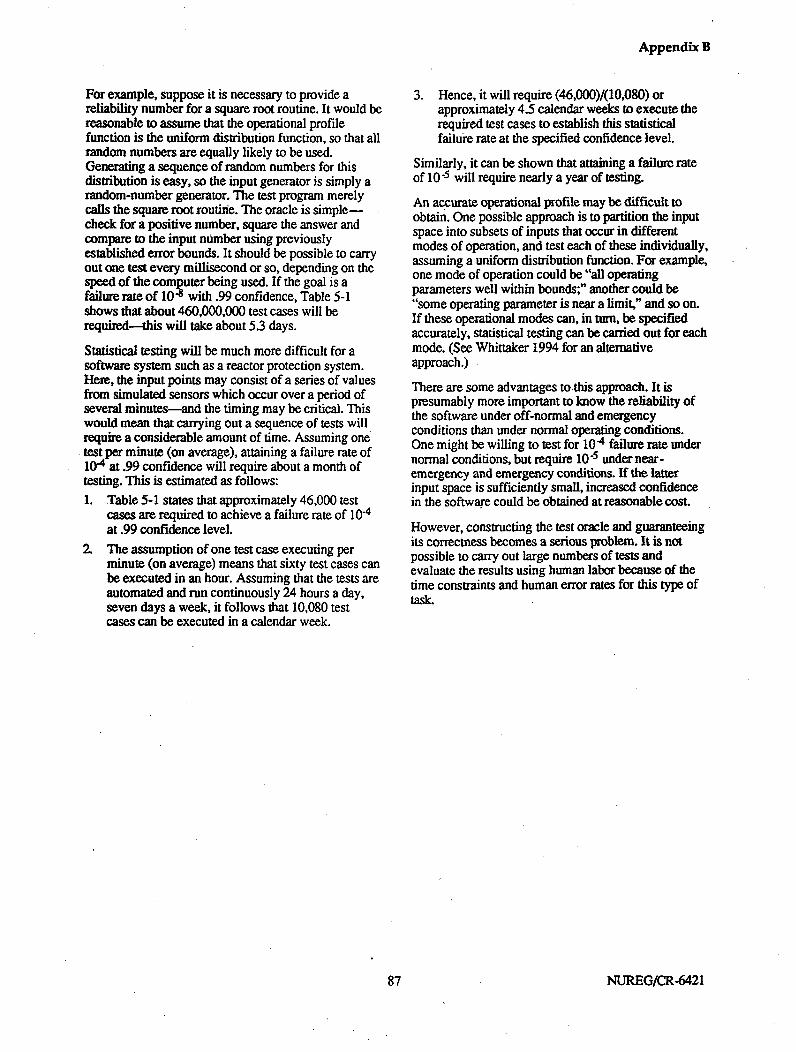
Appendix B
For example, suppose it is necessary to provide areliability number for a square root routine. It would bereasonable to assume that the operational profilefunction is the uniform distribution function, so that allrandom numbers are equally likely to be used.Generating a sequence of random numbers for thisdistribution is easy, so the input generator is simply arandom-number generator. The test program merelycalls the square root routine. The oracle is simple-check for a positive number, square the answer andcompare to the input number using previouslyestablished error bounds. It should be possible to carryout one test every millisecond or so, depending on thespeed of the computer being used. If the goal is afailure rate of 10-8 with .99 confidence, Table 5-1shows that about 460,000,000 test cases will berequired-this will take about 5.3 days.
Statistical testing will be much more difficult for asoftware system such as a reactor protection system.Here, the input points may consist of a series of valuesfrom simulated sensors which occur over a period ofseveral minutes-and the timing may be critical. Thiswould mean that carrying out a sequence of tests willrequire a considerable amount of time. Assuming onetest per minute (on average), attaining a failure rate of10-4 at .99 confidence will require about a month oftesting. This is estimated as follows:1. Table 5-1 states that approximately 46,000 test
cases are required to achieve a failure rate of 10-4at .99 confidence level.
2. The assumption of one test case executing perminute (on average) means that sixty test cases canbe executed in an hour. Assuming that the tests areautomated and run continuously 24 hours a day,seven days a week, it follows that 10,080 testcases can be executed in a calendar week.
3. Hence, it will require (46,000)/(10,080) orapproximately 4.5 calendar weeks to execute therequired test cases to establish this statisticalfailure rate at the specified confidence level.
Similarly, it can be shown that attaining a failure rateof 10-5 will require nearly a year of testing.
An accurate operational profile may be difficult toobtain. One possible approach is to partition the inputspace into subsets of inputs that occur in differentmodes of operation, and test each of these individually,assuming a uniform distribution function. For example,one mode of operation could be "all operatingparameters well within bounds;" another could be"some operating parameter is near a limit," and so on.If these operational modes can, in turn, be specifiedaccurately, statistical testing can be carried out for eachmode. (See Whittaker 1994 for an alternativeapproach.)
There are some advantages to this approach. It ispresumably more important to know the reliability ofthe software under off-normal and emergencyconditions than under normal operating conditions.One might be willing to test for 104 failure rate undernormal conditions, but require 10-5 under near-emergency and emergency conditions. If the latterinput space is sufficiently small, increased confidencein the software could be obtained at reasonable cost.
However, constructing the test oracle and guaranteeingits correctness becomes a serious problem. It is notpossible to carry out large numbers of tests andevaluate the results using human labor because of thetime constraints and human error rates for this type oftaskL
87 NUREG/CR-6421


Appendix B
6. STRESS TESTING
6.1. Purpose of Stress Testing
Stress testing is a process of subjecting a system toabnormal loads on resources in order to discoverwhether the system can function outside anticipatednormal ranges, to determine the usage limits beyondwhich the system will fail as a result of the overloadedresource, and to gain information that will help tocharacterize the behavior of a system when it isoperating near its usage limits. The process ofdiscovering "breaking points" also provides theopportunity to examine recovery mechanisms andprocedures.
If a system can function adequately with loads outsidethe anticipated real-life application domain levels, theassumption is that it will perform properly with normalloads (Perry 1988). Background testing (testing in thepresence of loads within normal ranges) should beperformed to help validate this assumption. Abackground test verifies that the system will performadequately within the normal mix of loads andresources and provides the basis with which tocompare stress test results.
Stress testing is parti cularly important for COTSsoftware items since those items may not have beendeveloped with the particular safety-related applicationin mind. This type of testing provides an opportunity toexamine the COTS software performance with respectto the intended application.
The qualities addressed by stress testing, summarizedin Table 1-2, are discussed below.
6.2. Benefits and Limitations of StressTesting
6.2.1. Benefits
Stres testing forces a system to operate in unusualcircumstances not typically created in other forms oftesting and, therefore, is complementary to otherelements of the overall testing effort. It is particularlyimportant for safety-related software since it is atesting strategy that creates high-stress, off-normalscenarios in which the software is likely to fail. Forreactor protection systems, these scenarios might berelated to sensor input streams of interrupt-type orbuffer loading signals or to output streams generated inemergency situations. Stress testing uncoversinformation about software faults and provides anunderstanding of limits on system resources. The latteris useful in validating the intended use of the COTS
item, in establishing system monitoring routines, and in,tuning the system for installed operations.
Stress testing provides information about robustnessand performance by creating scenarios in which normaloperating ranges are exceeded and examining howperformance degrades. Stress testing at the boundariesof these ranges also allows one to confirm thatperformance requirements have been met. The actualfailures encountered in stress testing may lead to thediscovery of software faults and provide opportunitiesto examine the completeness of the recoverymechanisms incorporated into the software.
6.2.2. Limitations
Stress testing must be performed in an actual orsimulated installed environment and requires completeinformation about operating and user procedures.Stress testing can be expensive because of manpowercosts or because of the need to develop automatedelements of the test station. In addition, specificinternal states can be difficult to reproduce, and rootcauses of failures can be difficult to find.
6.3. Information Required to PerformStress Testing
Stress testing must be performed in an actual orsimulated production (installed) environment.Therefore, complete information about thisenvironment must be available, including anunderstanding of operating and user procedures. Sincestress testing must provide abnormal loads, there mustbe a definition of the types of loads to be placed on thesystem as well as an understanding of what the normaloperating ranges will be for each load. Typical loadtypes of interest are as follows (the first four being ofparticular interest for reactor protection systems):
* High volumes and arrival rates of transactions
* Saturation of communications and processorcapacities
* Situations stressing internal table sizes
* Situations stressing internal sequencing orscheduling operations
* Heavy use of disk storage space and swappingcapability
* Operating with a very large database size
. Many simultaneous users.
89 89 NUREG/CR-6421

Appendix B
Finally, if available, design information is valuable inorder to understand how to design specific stress teststhat will focus on internals.
6.4. Methods of Performing Stress Testing
The stress tests must be planned, designed, created,coordinated, executed, evaluated, and documented.
6.4.1. Test Planning and Test Requirements
The following actions are required to plan and generaterequirements for stress testing.
1. Determine the software qualities to be addressedwith stress testing. The primary quality of interestfor safety-related COTS software is robustness inthe intended role;, however, availability,completeness, correctness, and performance arealso addressed.
2. Determine the load situations under which thesoftware system is to be tested. For safety-relatedCOTS software, these will be determined based onknowledge of the role that the COTS product willplay in the system and vendor-suppliedinformation regarding product functions andperformance. Information derived from the usageexperience of other users of the COTS softwareitem or from fault tree analyses of the system isalso valuable. in this process.
3. Determine whether the stress testing environmentwill be an actual or simulated productionenvironment.
4. Determine the resources required to carry out thetesting. Resources include budget, schedule,personnel, equipment, test tools, test station, andtest data.
5. Determine the criteria to be used to decide howmuch testing will be required. This is a stoppingcriterion-how much testing is enough? Forexample, "stres testing of a particular softwareresource might continue until adequateinformation has been gathered regarding all threegoals of stress testing."
6.4.2. Test Design and Test Implementation
The following actions are required to design andimplement stress testing.
1. Establish the testing environment for the stresstests.
In most cases, a simulated production environment willbe required. Since the results of stress testing willreflect the performance of the software in the testenvironment rather than the real-life environment, the
simulated production environment should be as closeas possible to the actual production environment.
2. Create procedures for executing the stress tests.
Since this testing will take place in an actual orsimulated production environment, the test proceduresshould make use of system operating procedures andusage procedures or user guides. The stress testprocedures specify how the system loads will begenerated, the roles of all participants, the sequences ofoperations (scripts) each participant will perform, thetest cases to be performed, and how the test results willbe logged.
3. Create individual test cases.
Each test case should contain the followinginformation:
a Test identification. Each test case must have aunique identifier.
b. Purpose. Each test case should have a specificreason for existing. Examples include verifyingthe proper operation of a system function,verifying response times, and verifying thehandling of exception conditions during situationsof high system loads.
c. Input data. The precise data required in order toinitiate the test case must be specified.
d. Initial state. The initial state for the test case isessentially specified in the test procedures andscripts; however, there may be initial stateinformation specific to a given test case.
e. Test results. The expected results of the test mustbe known and specified. Expected performancestatistics, counts of operations, etc., should bedetermined from the planned load and test caseinput data.
f Final state. In some cases, the final state isimportant and must be specified as part of the testcase information.
4. Create the test station.
The test station is a mechanism for specifying andgenerating loads as well as selecting, executing,evaluating, and recording the results of other testscarried out on the software. Note that, depending onthe goal of a particular stress (or background) test,input may consist solely of transactions in the inputload or may be augmented by rest cases from othertypes of testing. Test station components (patternedafter Beizer 1984) are illustrated in Figure 6-1 andinclude:
NUREG/CR-6421 990

Appendix B
Figure 6-1. Typical Test Station Components
a. Load data generator. A means of acceptingspecifications for the loading of resources andgenerating scenarios needed for the input loadgenerator to produce the required load during thestress test rum.
b. Test case selection. A means of selecting, ifappropriate, additional test cases to be executed.Test case information is typically kept in a file ordatabase, and the selection may simply consist of"get next test case."
cQ Input load generation. A means of accepting inputdata for loading and generating the desired systemloads with the desired statistical characteristics.
d. Test Oracle. A means of determining thecorrectness of the output (of the optional testcases) produced by the software object under test.
e. Data Logger. A means of logging pertinentinformation about system performance during theStress test.
f Test evaluation. A means of analyzing the resultsof the stress test, including specific test caseresults as well as scanning software system outputfor anomalies created during the stress test.
g. Results database. A means of recording the testresults for future analysis and evaluation.
6.4.3. Test Execution and Test Evaluation
The test procedures must be carried out and the testresults must be analyzed. The logged system outputs,produced in response to the input load or anyadditional test cases, must be examined to verifycorrect operation of the system. This is done bycomparing. inputs and outputs relating to specific testcases or transactions to determine if information was
91 91 NUREG/CR-6421

Appendix B
lost or improperly processed. In addition, the loggedoutput must be analyzed to determine if timing,sequencing, counts, error recovery, etc. match whatwas input to the system by the load generator and testcase selector. If appropriate, database integritychecking routines should be run. If a particular loadcauses the system to fail, the logged information isused to search for the circumstances of the failure andto quantify the load level at which the failure occurred.These evaluations can be quite difficult to performsince they can require the careful examination ofvoluminous data..
The results of stress testing may indicate that thesystem performs acceptably within the planned loadranges of the tested resources. In this case, the stresstesting results provide operating information aboutresource limits that can then be embedded into systemmonitoring routines or used for system tuningpurposes.
The performance profile and the nature of faultsencountered must also be considered. The performanceinformation must be verified against the requirementsand constraints of the system in which the COTSsoftware will operate. The significance of the faultsdiscovered should be evaluated and, if appropriate, theoptions for obtaining corrections might be pursued. Ifthe performance of the software is not within therequirements of the application or if one or moreserious faults are discovered, confidence decreasesrapidly regarding the suitability of the product for usein a safety-related application.
6.5. Discussion of Stress Testing
Stress testing is a process of subjecting a system toabnormal loads with the intention of breaking thesystem. By investigating why the system breaks and atwhat load level the system breaks, information isgained about possible software faults, operating loadlimits, system behavior near the load limits, and errorrecovery behavior. Typical software faults discoveredare faults associated with sequencing, contention forresources, scheduling priorities, error or time-outrecovery paths, and simultaneous activities. Thesefaults tend to be subtle and frequently indicate designproblems rather than simple coding mistakes (Beizer1984).
For COTS software, there are a number of approachesto identifying specific load situations to test. The roleof COTS software in the overall system must becharacterized with respect to functions provided,performance requirements, and interfaces to otherelements of the system--essentially a black-boxcharacterization. Additional information can be addedbased on any available vendor data regarding productspecification and target performance levels. If sourcecode is available, the source code inspection process
(see Section 2) could have, as one of its goals, a focuson identifying structural properties that should be stresstested. Information can also be gathered from otherusers of the COTS software item regarding usageexperience and load ranges. This information mightsuggest suspect areas or provide additional confidencethat some areas are robust. Finally, if fault tree analysistechniques, are applied to the overall system, any rootcauses possibly relating to the COTS software rolemust be examined to see if load-related failures mightbe possible.
With respect to the task of diagnosing software faultsbased on stress test results, it should be noted that theexact reproduction of internal states resulting fromstress test scenarios is difficult, if not impossible. Thisis because the simultaneous activities of testparticipants and the various internal timing andscheduling situations are usually not exactlyrepeatable. Therefore, the process of identifyingsoftware faults based on stress test results is not asdeterministic as it is for other types of test resultsanalysis. However, if the goal is to examine generalbehavior at various load levels, the stored scenarios canbe re-mun as needed. Discovered software failures thatare reproducible without active system loads can befurther investigated with other test techniques. It ismore difficult to diagnose software failures that occuronly under high system loads or that cannot bereproduced in subsequent stres tests. For this reason, itis important to have full knowledge of test inputs andto log as much information as possible during the stresstest execution for subsequent analysis. For COTSsoftware items, knowledge of the experience of otherusers and a characterization of their normal operatingloads is useful ancillary information for analysis of testresults.
Creating mechanisms for generating the required loads,logging test data, and analyzing results is a difficulttask. For small systems with minimal real-timerequirements or in cases in which only generalinformation such as user response time is desired, it ispossible to do the data generation manually and tocreate the system load via interactive user inputsaugmented by other system functions such as runningreports and performing intense data searches. Datalogging would be done manually or automaticallyusing existing logging features, and test results analysiswould be manual. Even though there might not be aneed for developing automated load generators in thesecases, there will still be a signifi cant effort to use andcoordinate manpower and system resources for stresstesting.
For most situations, it is necessary to developautomated means for generating the input loads,logging data, and analyzing results. See Beizer 1984for a detailed discussion of load generation techniques.
NUREG/CR-642I 992
Appendix B
The load generation process comprises two pans,which can be combined or separated depending on thedemands of the stress testing operations. First, theinformation characterizing a particular load is used togenerate typical test data according to statisticaldistributions of desired input parameters. Second, anautomated means for using this data to generate loads
in real time during the test must be created. Loggingfacilities might already exist in the system platform; ifnot, they have to be created. Finally, the analysis ofresults will require specialized routines to organize andsummarize the data, scan the results for possibleanomalies, and compare system performance statisticswith those anticipated from the input load statistics.
93 NUREGICR-6421


Appendix B
7. REGRESSION TESTING
7.1. Purpose of Regression Testing
Regression testing consists of re-running a standard setof test cases following the implementation of a set ofone or more changes to previously tested software. Itspurpose is to provide confidence that modificationshave not had unintended effects on the behavior of thesoftware. It is assumed that the appropriate testingtechniques (see the other sections of this report) havebeen applied to test whether the modified softwareelements perform as specified in the changedocumentation. In addition to regression testing itself,it is necessary to verify that all system documentation,such as requirements, design, and operatingprocedures, have been updated to reflect the softwaremodifications. Regression testing addresses the qualityof software correctness and, indirectly, the qualitiesassociated with the test strategies that are being re-applied.
7.2. Benefits and Limitations of RegressionTesting
7.2.1. Beniefits
In addition to the direct testing of softwaremodifications, regression testing is required to provideassurance that, except for the modified portion, thesoftware performs in the same way that it did prior tothe changes. Since the regression testing processrepeats previous testing, no additional "start-up" costsare associated with establishing test mechanisms. Inaddition, since the regression testing effort is largelythe same for each software change, there is benefit incombining changes into one release. For COTSsoftware, this is equivalent to determining when toupgrade to a new release.
The primary software quality of interest in regressiontesting is correctness since the goal is to verify thatnew faults have not been inadvertently introduced intothe software. Since regression testing consists of re-rnning test cases from appropriate test techniques, thequalities associated with those techniques are also re-examined during regression testing.
7a2. Limitations
There are significant maintenance costs forconfiguration management of the test cases, test data,and test procedures as well as for keeping the testingenvironment(s) current. Regression testing will involvere-running large numbers of test cases in a variety oftypes of testing and will, therefore, be expensive toperform-
7.3. Information Required to PerformRegression Testing
Since regression testing is a re-use of exist ing testcases, 13 the information required to perform thistesting depends upon the specific types of test cases tobe re-run. This information is described in the sectionsof this report dealing with the test types of interest. It isessential that configuration control be maintained onall test documentation and related test materials topermit regression testing to be performed effectivelyand efficiently.
7.4. Methods of Performing RegressionTestingThe regression tests must be planned, designed,coordinated, executed, evaluated, and documented.
7.4.1. Test Planning and Test Requirements
The following actions are required to pla and generaterequirements for regression testing.
1. Establish and maintain the standard set of tests(test cases, data, and procedures) to be repeated asregression tests. For COTS software used in asafety-related context, it is recommended that thefull set of functional and stress testing initiallyconducted be repeated.
2. Determine what resources will be required in orderto carry out the testing. Resources include budget,schedule, personnel, equipment, test tools, teststation(s), and test data. The test tools, teststation(s), and test data should already be in placefrom previous testing activity, and should bedirectly usable provided that configurationmanagement procedures have been continuouslyapplied to these items.
3. Determine the criteria to be used to decide howmuch testing will be required. This is a stoppingcriterion-how much testing is enough? Forexample, "the regression testing process willcontinue until the entire standard set of test casesruns without incident."
7.4.2. Test Design and Test Implementation
The following actions are required to design andimplement regression testing.
U3 As a system evolves, the suite of test cases used for regressiontesting must also evolve.
95 95 NUREG/CR-6421

Appendix B
1. Ensure that the testing environments used inprevious testing have been maintained and areready for regression testing.
2. Ensure that the modified software elements havebeen tested according to the same testing plansused on the original software.
3. Review the standard set of regression test cases,data, and procedures to discover whether any havebeen invalidated as a result of the desiredmodifications. Update the test cases andprocedures as appropriate.
7.4.3. Test Execution and Test Evaluation
Thbe test procedures must be carried out and the testresults analyzed. Since the modified software elementshave already been tested to verify' correct operation, theregression test results should indicate that the areas ofthe.COTS software thought to have been unaffected bythe modifications are indeed unaffected by thechanges. The results should exactly match the resultsof previous, successful tests.
7.5. Discussion of Regression Testing
The primary focus of regression testing is to provideassurance that implemented changes do not, in somesubtle way, ripple through the system and causeunintended effects. In addition to software function andperformance, there must be a verification thatconventions, standards, access rules, etc., were adheredto in the change implementation. One source ofproblems occurring in software maintenance is that
undocumented assumptions made by the developmentteam are not carried over into the maintenance phase(Hetzel 1984). For these reasons, it is recommendedthat the full complement of functional and stresstesting activities originally performed be repeated totest the modified safety-related software system. (It isassumed that appropriate tests and. analyses willalready have been run on the modified code.)Depending on the role of the modified softwareelement and the criticality of its function (and of theoverall software system), it may be possible to justify areduced set of test cases for regression testing based ona change impact assessment and knowledge ofpotential fault consequences derived from a softwarerisk assessment. This requires a careful assessment ofthe modified software element and its interfaces(logical and data) to other parts of the system, as wellas a complete understanding of the likelihood andmagnitudes of potential loss.
The methods used for regression testing are the samemethods used for the various types of testing carriedout previously. Test plans, test cases, and testprocedures, as well as test stations and automated testsupport mechanisms, already exist, and it is assumedthat they have been maintained under configurationcontrol for future use in regression testing. Whenevermodifications are made to the software object,, it isnecessary to review the standard set of test cases (aswell as test data and test procedures) to ensure thatnone have been invalidated by the modifications and toupdate the set based on the specifications for the newlymodified object.
NUREG/CR-6421 996

Appendix B
8. REFERENCES
Basili, Victor R. and Richard W. Selby, "Comparing the Effectiveness, of Software Testing Strategies," IEEETransactions on Software Engineering Vol. 12, No. 12 (December 1987), 1278-1296.
Beizer, Boris, Software System Testing and Quality Assurance, Van Nostrand Reinhold (1984).Beizer, Boris, Software Testing Techniques, Van Nostrand Reinhold (1990).Charette, Robert N., Software Engineering Risk Analysis and Management, McGraw-Hill (1989).Dyer, Michael, The Cleanroom Approach to Quality Software Development, John Wiley & Sons (1992).Fagan, M. E., "Design and Code Inspections to Reduce Errors in Program Development," IBM Systems Journal,
Vol. 15, No. 3, 1976, 182-211.
Glass, Robert L., Building Quality Software, Prentice-Hall (1992).Hamlet, Richard, "Random Testing," in Encyclopedia of Software Engineering, John Wiley & Sons, 1994.Hetzel, William, The Complete Guide to Software Testing, QED Information Sciences, Inc. (1984).
Howden, William E., "A Survey of Static Analysis Methods," in Tutorial: Software Testing & ValidationTechniques, Institute of Electrical and Electronics Engineers, 1981.
Howden, William E., "A Survey of Dynamic Analysis Methods," in Tutorial: Software Testing & ValidationTechniques, Institute of Electrical and Electronics Engineers, 1981.
Howden, William E., Functional Program Testing and Analysis; McGraw-Hill (1987).Hurley, Richard B., Decision Tables in Software Engineering, Van Nostrand Reinhold, (1983).IEEE 610.12. IEEE Standard Glossary of Software Engineering Terminology, Institute of Electrical and Electronics
Engineers, 1991.IEEE 829. IEEE Standard for Software Test Documentation, Institute of Electrical and Electronics Engineers, 1983.IEEE 1008. IEEE Standard for Software Unit Testing, Institute of Electrical and Electronics Engineers, 1986.MEEE 1074. IEEE Standard for Developing Software Life Cycle Processes, Institute of Electrical and Electronics
Engineers, 1992.
Lawrence, J. Dennis, Software Reliability and Safety in Nuclear Reactor Protection Systems, NUREG/CR-6101,Lawrence Livermore National Laboratory, Livermore, CA (1993).
Lawrence, J. Dennis and Preckshot, G. G., Design Factors for Safety-Critical Software, NUREG/CR-6294,Lawrence Livermore National Laboratory, Livermore, CA (1994).
Marick, Brian, The Craft of Software Testing; Prentice-Hall (1995).Miller, Edward and William E. Howden, Tutorial: Software Testing and Validation Techniques, Second Edition,
IEEE Computer Society Press (1981).McCall, Jim A. et al., "Factors in Software Quality," Concept and Definitions of Software Quality, General Electric
Company, 1977.
Musa, John D., "The Operational Profile in Software Reliability Engineering: An Overview," Third Int'l Symp. onSoft. Rel. Eng. (October 1992), 140-154.
Olender, Kurt M. and Leon J. Osterweil, "Cecil: A Sequencing Constraint Language for Automatic Static AnalysisGeneration," IEEE Transactions on Software Engineering, Vol. 16, No. 3, March 1990, 268-280.
Perry, William E., A Structured Approach to Systems Testing, QED Information Sciences (1988).Pressman, Roger S., Software Engineering, A Practitioner's Approach, McGraw-Hill, (1987).Price, Source Code Static Analysis Tools Report, Software Technology Support Center, 1992.Poore, J. H., Harlan D. Mills, and David Mutchler, "Planning and Certifying Software System Reliability," IEEE
Software 10, 1 (January 1993), 88-99.Preckshot, G. G. and Scott, J. A., Vendor Assessment and Software Plans, UCRL-ID-122243, Lawrence Livermore
National Laboratory, Livermore, CA (1995).Whittaker, James A., and Michael G. Thomason, "A Markov chain model for statistical software testing," IEEE
Transactions on Software Engineering, Vol. 20, No. 10 (October 1994), 812-824.Yourdon, Edward, Structured Walkthroughs, Prentice-Hall (1989).
97 NUREG/CR-6421


Appendix B
ANNEX: TAXONOMY OF SOFTWARE BUGS
This Annex* provides a taxonomy for program faults (bugs). Faults are categorized by a four-digit number, perhapswith sub-numbers using the point system: e.g., "1234.5.6." The "x" that appears is a place holder for possible futurefilling in of numbers as the taxonomy is expanded. For example,
3xxx-structural bugs in the implemented software
32xx-processing bugs322x-expression evaluation
3222--arithmetic expressions3222.1-wrong operator
Ixxx: FUNCTIONAL BUGS: REQUIREMENTS AND FEATURES: Bugs having to do with requirements asspecified or as implemented.
11xx: REQUIREMENTS INCORRECT: the requirement or a part of it is incorrect.111x: Incorrect: requirement is wrong.112x: Undesirable: requirement is correct as stated but it is not desirable.113x: Not needed: requirement is not needed.
12xx: LOGIC: the requirement is illogical or unreasonable.121x: Illogical: illogical, usually because of a self-contradiction which can be exposed by a logical analysis
of cases.122x: Unreasonable: logical and consistent but unreasonable with respect to the environment and/or
budgetary and time constraints.123x: Unachievable: requirement fundamentally impossible or cannot be achieved under existing
constraints.124x: Inconsistent, incompatible: requirement is inconsistent with other requirements or with the
environment.1242: Internal: the inconsistency is evident within the specified component.1244: External: the inconsistency is with external (to the component) components or the environment.1248: Configuration sensitivity: the incompatibility is with one or more configurations (hardware,
software, operating system) in which the component is expected to work.
13xx: COMPLETENESS: the requirement as specified is either ambiguous, incomplete, or overly specified.131x: Incomplete: the specification is incomplete; cases, features, variations or attributes are not
specified and therefore riot implemented.132x: Missing, unspecified: the entire requirement is missing.,133x: Duplicated, overlapped: specified requirement totally or partially overlaps another requirement
either already implemented or specified elsewhere.134x: Overly generalized: requirement as specified is correct and consistent but is overly generalized
(e.g., too powerful) for the application.137x: Not downward compatible: requirement as specified will mean that objects created or
manipulated by prior versions can either not be processed by this version or will be incorrectlyprocessed.
138x: Insufficiently extendible: requirement as specified cannot be expanded in ways that are likelyto be needed-important hooks are left out of specification.
This Annex is based on "Bug Taxonomy and Statistics," Appendix. Sofi ware Testing Techniques, second edition, by Boris Beizer. Copyright ©
1990 by Boris Beizer. Reprinted with permission of Van Nostrand Reinhold, New York.
99 NUREG/CR-6421

Appendix B
14xx: VERIFIABILITY: specification bugs having to do with verifying that the requirement was correctly orincorrectly implemented.
141x: Unverifiable: the requirement, if implemented, cannot be verified by any means or withinavailable time and budget. For example, it is possible to design a test, but the outcome of the testcannot be verified as correct or incorrect.
142x: Untestable: it is not possible to design and/or execute tests that will verify the requirement.Untestable is stronger than unverifiable.
lSxx: PRESENTATION: bugs in the presentation or documentation of requirements. The requirements arepresumed to be correct, but the form in which they are presented is not. This can be important for testdesign automation systems, which demand specific formats.
152x: Presentation, documentation: general presentation, documentation, format, media, etc.
153x: Standards: presentation violates standards for requirements.
16xx: REQUIREMENT CHANGES: requirements, whether or not correct, have been changed between thetime programming started and testing ended.162x Features: requirement changes concerned with features.
1621: Feature added: a new feature has been added.1632: Feature deleted: previously required feature deleted.1633: Feature changed: significant changes to feature, other than changes in cases.
163x: Cases: cases within a feature have been changed. Feature itself is not significantly modified exceptfor cases.1631: Cases added.1632: Cases deleted.1633: Cases changed: processing or treatment of specific case(s) changed.
164x: Domain changes: input data domain modified: e.g., boundary changes, closure, treatment.165x: User messages and diagnostics: changes in text, content, or conditions under which user prompts,
warning, error messages, etc. are produced.166x: Internal interfaces: direct interfaces (e.g., via data structures) have been changed.167x: External interfaces: external interfaces, such as device drivers, protocols, etc. have been changed.168x: Performance and timing: changes to performance requirements (e.g., throughput) and/or timings.
2xxx: FUNCTIONALITY AS IMPLEMENTED: requirement known or assumed to be correct, implementable,
and testable, but implement is wrong.
21xx: CORRECTNESS: having to do with the correctness of the implementation.211x: Feature misunderstood, wrong: feature as implemented is not correct-not as specified.218x: Feature interactions: feature is correctly implemented by itself, but has incorrect interactions with
other features, or specified or implied interaction is incorrectly handled.
22xx: COMPLETENESS, FEATURES: having to do with the completeness with which features areimplemented.221x: Missing feature: an entire feature is missing.222x: Unspecified feature: a feature not specified has been implemented.223x: Duplicated, overlapped feature: feature as implemented supplicates or overlaps features
implemented by other parts of the software.
23xx: COMPLETENESS, CASES: having to do with the completeness of cases within features.
231x: Missing case.232x: Extra case: cases that should not have been handled are handled.233x: Duplicated, overlapped case: duplicated handling of cases or partial overlap with other cases.234x: Extraneous output data: data not required are output
24xx: DOMAINS: processing case or feature depends on a combination of input values. A domain bug exists ifthe wrong processing is executed for the selected input-value combination.
NUREG/CR-6421 100
Appendix B
241x: Domain misunderstood, wrong: misunderstanding of the size, shape, boundaries, or othercharacteristics of the specified input domain for the feature or case. Most bugs related to handlingextreme cases are domain bugs.
242x: Boundary locations: the values or expressions that define a domain boundary are wrong: e.g.,"X>=6" instead of "X>=3."
243x: Boundary closures: end points and boundaries of the domain are incorrectly associated with anadjacent domain: e.g., "X>=O" instead of "X>O".
244x: Boundary intersections: domain boundaries are defined by a relation between domain controlvariables. That relation, as implemented, is incorrect: e.g., "IF X>O AND Y>O..." instead of "IF X>OOR Y>0...".
25xx: USER MESSAGES AND DIAGNOSTICS: user prompt or printout or the form of communication isincorrect. Processing is assumed to be correct: e.g., false warning, failure to warn, wrong message, spelling,formats.
26xx: EXCEPTION CONDITIONS MISHANDLED: exception conditions such as illogical, resourceproblems, failure modes, which require special handling, are not correctly handled or the wrong exception -handling mechanisms are used.
3xxx: STUCTURAL BUGS: bugs related to the component's structure: i.e., the code.
31xx: CONTROL FLOW AND SEQUENCING: bugs specifically related to the control flow of the programor the order and extent to which things are done, as distinct from what is done.311x: General structure: general bugs related to component structure.
3112: Unachievable path: a functionally meaningful processing path in the code for which there is nocombination of input values that will force the path to be executed. Do not confuse withunreachable code. The code in question might be reached by some other path.
3114: Unreachable code: code for which there is no combination of input values that will cause thatcode to be executed.
3116: Dead-end code: code segments that once entered cannot be exited, even though it was intendedthat an exit be possible.
312x: Control logic and predicates: the path taken through a program is directed by control flowpredicates (e.g., Boolean expressions). This category addresses the implementation of such predicates.3122: Duplicated logic: control logic that should appear only once is inadvertently duplicated in
whole or in part.3124: Don't care: improper handling of cases for which what is to be done does not matter either
because the case is impossible or because it really does not matter: e.g., incorrectly assuming thatthe case is a don't-care case, failure to do case validation, not invoking the correct exceptionhandler, improper logic simplification to take advantage of such cases.
3126: Illogicals: improper identification of, or processing of, illogical or impossible conditions. Anillogical is stronger than a don't care. Illogicals usually mean that something bad has happenedand that recovery is needed. Examples of bugs include: illogical not really so, failure to recognizeillogical, invoking wrong handler, improper simplification of control logic to take advantage of thecase.
3128: Other control-flow predicate bugs: control-flow problems that can be directly attributed to theincorrect formulation of a control flow predicate: e.g., "IF A>B THEN ..." instead of "IF A<BTH BEN ... ".
313x: Case selection bug: simple bugs in case selections, such as improperly formulated case selectionexpression. GOTO list, or bug in assigned GOTO.
314x: Loops and iteration: bugs having to do with the control of loops.3141: Initial value: iteration value wrong: e.g., "FOR 13 TO 17 ..." instead of "FOR 1=8 TO 17."3142: Terminal value or condition: value, variable, or expression used to control loop termination is
incorrect: e.g., "FOR I = I TO 7 ..." instead of "FOR I = 1 TO 8."3143: Increment value: value, variable, or expression used to control loop increment value is
incorrect: e.g., "FOR I = 1 TO 7 STEP 2 ..." instead of "FOR I = 1 TO 7 STEP 5 ...".
101 NUREG/CR-6421

Appendix B
3144: Iteration variable processing: where end points and/or increments are controlled by valuescalculated within the loop's scope, a bug in such calculations.
3148: Exception exit condition: where specified values or conditions or relations between variablesforce an abnormal exit to the loop, either incorrect processing of such conditions or incorrect exitmechanism invoked.
315k: Control initialization and/or state: bugs having to do with how the program's control flow isinitialized and changes of state that affect the control flow: e.g., switches.3152: Control initialization: initializing to the wrong state or failure to initialize.3154: Control state: for state-determined control flows, incorrect transition to a new state from the
current state: e.g., input condition X requires a transition to state B, given that the program is instate A; instead, the transition is to state C. Most incorrect GOTOs are included in this category.
316x: Incorrect exception handling: any incorrect invocation of a control-flow exception handler notpreviously categorized.
32xx: PROCESSING: bug related to processing under the assumption that the control flow is correct.321x: Algorithmic, fundamental: inappropriate or incorrect algorithm selected, but implemented
correctly: e.g., using an incorrect approximation, using a shortcut string search algorithm that assumesstring characteristics that may not apply.
322x: Expression evaluation: bugs having to do with the way arithmetic, Boolean, string, and otherexpressions are evaluated.3222: Arithmetic: bugs related to evaluated of arithmetic expression.
3222.1: Operator: wrong arithmetic operator or function used.3222.2: Parentheses: syntactically correct bug in placement of parentheses or other
arithmetic delimiters.3222.3: Sign: bug in use of sign.
3224: Logical or Boolean, not control: bug in the manipulation or evaluation of Boolean expressionthat are not (directly) part of control-flow predicates: e.g.. using wrong mask, AND instead of OR,incorrect simplification of Boolean function.
3226: String manipulation: bug in string manipulation.3226.1: Beheading: the beginning of a string is cut off when it should not have been, or
not cut off when it should have been.3226.2: Curtailing: as for beheading but for string end.3226.3: Concatenation order: strings are concatenated in wrong order or concatenated
when they should not be.3326.3.1: Append instead of precede.3226.3.2: Precede instead of append.
3226.4: Inserting: having to do with the insertion of one string into another.3226.5: Converting case: case conversion (upper to lower, say) is incorrect.3226.6: Code conversion: string is converted to another code incorrectly or not
converted when it should be.3226.7: Packing, unpacking: strings are incorrectly packed or unpacked.
3228: Symbolic, algebraic: bugs in symbolic processing of algebraic expressions.323x: Initialization: bugs in initialization of variables, expressions, functions, etc. used in processing,
excluding initialization bugs associated with declarations and data statements and loop initialization.324x: Cleanup: incorrect handling of cleanup of temporary data areas, registers, states, etc. associated with
processing.325x: Precision, accuracy: insufficient or excessive precision, insufficient accuracy, and other bugs
related to number representation system used.326x: Execution time: excessive (usually) execution time for processing component.
4mx: DATA: bugs in the definition, structure, or use of data.
NUREG/CR-642110 102
Appendix B
41xx: DATA DEFINITION, STRUCTURE, DECLARATION: bugs in this definition, structure, andinitialization of data: e.g., in DATA statements. This category applies whether the object is declaredstatically in source code or created dynamically.411x: Type: the data object type, as declared, is incorrect: e.g., integer instead of floating, short instead of
long, pointer instead of integer, array instead of scalar, incorrect user-defined type.412x: Dimension: for arrays and other objects that have a dimension (e.g., arrays, records, files) by which
component objects can be indexed, a bug in the dimension, in the minimum or maximum dimensions,or in redimensioning statements.
413x: Initial, default values: bugs in the assigned initial values of the object (e.g., in DATA statements),selection of incorrect default values, or failure to supply a default value if needed.
414x: Duplication and aliases: bugs related to the incorrect duplication or failure to create a duplicatedobject.4142: Duplicated: duplicated definition of an object where allowed by the syntax.4144: Aliases: object is known by one or more aliases but specified alias is incorrect: object not
aliased when it should have been.415x: Scope: the scope, partition, or components to which the object applies is incorrectly specified.
4152: Local should be global: a locally defined object (e.g., within the scope of a specific component)should have been specified more globally (e.g., in COMMON)
4154: Global should be local: the scope of an object is too global: it should have been declared morelocally.
4156: Global/local inconsistency or conflict: a syntactically acceptable conflict between a localand/or global declaration of an object (e.g., incorrect COMMON).
416x: Static/dynamic resources: related to the declaration of static and dynamically allocated resources.4162: Should be static resource: resource is defined as a dynamically allocated object but should
have been static (e.g., permanent).4164: Should be dynamic resource: resource is defined as static but should have been declared as
dynamic.4166: Insufficient resources, space: number of specified resources is insufficient or there is
insufficient space (e.g., main memory, cache, registers, disc) to hold the declared resources.4168: Data overlay bug: data objects are to be overlaid but there is a bug in the specification of the
overlay areas.
42xx: DATA ACCESS AND HANDLING: having to do with access and manipulation of data objects that arepresumed to be correctly defined.421x: Type: bugs having to do with the object type.
4212: Wrong type: object type is incorrect for required processing: e.g., multiplying two strings.4314: Type transformation: object undergoes incorrect type transformation: e.g., integer to floating,
pointer to integer, specified type transformation is not allowed, required type transformation notdone. Note: type transformation bugs can exist in any language, whether or not it is strongly typed,whether or not there are user-defined types.
4216: Scaling, units: scaling or units (semantic) associated with objects is incorrect, incorrectlytransformed or not transformed: e.g., FOOT-POUNDS to STONE-FURLONGS.
422x: Dimension: for dynamically variable dimensions of a dimensioned object, a bug in the dimension:e.g., dynamic redimension of arrays, exceeding maximum file length, removing one or more than theminimum number of records.
423x: Value: having to do with the value of data objects or parts thereof.4232: Initialization: initialization or default value of object is incorrect. Not to be confused with
initialization and default bugs in declarations. This is a dynamic initialization bug.4234: Constant value: incorrect constant value for an object: e.g., a constant in an expression.
424x: Duplication and aliases: bugs in dynamic (run time) duplication and aliasing of objects.4242: Object already exists: Attempt to create an object that already exists.4244: No such object: attempted reference to an object that does not exist.
103 NUREG/CR-6421
Appendix B
426x: Resources: having to do with dynamically allocated resources and resource pools, in whatevermemory media they exist: main, cache, disc, bulk RAM. Included are queue blocks, control blocks,buffer blocks, heaps, files.4262: No such resource: reference resource does not exist.4264: Wrong resource type: wrong resource type reference.
428x: Access: having to do with access of objects as distinct from the manipulation of objects. In thiscontext, accesses include read, write, modify, and (in some instances) create and destroy.4281: Wrong object accessed: incorrect object accessed: e.g., "X:=ABC33" instead of "X:=ABD33".4282: Access rights violation: access rights are controlled by attributes associated with the caller and
the object. For example, some callers can only read the object, others can read and modify.Violations of object access rights are included in this category whether or not a formal accessrights mechanism exits: that is, access rights could be specified by programming conventionsrather than by software.
4283: Data-flow anomaly: data-flow anomalies involve the sequence of accesses to an object: e.g.,reading or initializing an object before it has been created, or creating and than not using.
4284: Interlock bug: where objects are in simultaneous use by more than one caller, interlocks andsynchronization mechanisms may be used to ensure that all data are current and changed by onlyone caller at a time. These are not bugs in the interlock or synchronization mechanism but in theuse of that mechanism.
4285: Saving or protecting bug: application requires that the object be saved or otherwise protectedin different program states or, alternatively, not protected. These bugs are related to the incorrectusage of such protection mechanisms or procedures.
4286: Restoration bug: application requires that a previously saved object be restored prior toprocessing: e.g., POP the stack, restore registers after interrupt. This category includes bugs in theincorrect restoration of data objects and not bugs in the implementation of the restoration of dataobjects and not bugs in the implementation of the restoration mechanism.
4287: Access mode, direct/indirect: object is accessed by wrong means: e.g., direct access of anobject for which indirect access is required: call by value instead of name, or vice versa: indexedinstead of sequential, or vice versa.
4288: Object boundary or structure: access to object is partly correct, but the object structure and itsboundaries are handled incorrectly: e.g., fetching 8 characters of a string instead of 7, mishandlingword boundaries, getting too much or too little of an object.
Sxxx: IMPLEMENTATION: bugs having to do with the implementation of the software. Some of these, such asstandards and documentation, may not affect the actual workings of the software. They are included in the bugtaxonomy because of their impact on maintenance.
Slxx: CODING AND TYPOGRAPHICAL: bugs that can be clearly attributed to simple coding, as well astypographical bugs. Classification of a bug into this category is subjective. If a programmer believed thatthe correct variable, say, was "ABCD" instead of "ABCE", than it would be classified as a 4281 bug(wrong object accessed). Conversely, if E was changed to D because of a typewriting bug, then it belongshere.511x: Coding wild card, typographical: all bugs that can be reasonably attributed to typing and other
typographical bugs.512x: Instruction, construct misunderstood: all bugs that can be reasonably attributed to a
misunderstanding of an instruction's operation or HOL statement's action.
S2xx: STANDARDS VIOLATION: bugs having to do with violating or misunderstanding the applicableprogramming standards and conventions. The software is assumed to work properly.521x: Structure violations: violations concerning control-flow structure, organization of the software, etc.
5212: Control flow: violations of control-flow structure conventions: e.g., excessive IF-THEN-ELSEnesting, not using CASE statements where required, not following dictated processing order,jumping into or out of loops, jumping into or out of decisions.
5214: Complexity: violation of maximum (usually) or minimum (rare) complexity guidelines asmeasured by some specified complexity metric: e.g., too many lines of code in module, cyclomaticcomplexity greater than 200, excessive Halstead length, too many tokens.
NUREG/CR-6421 104
Appendix B
5215: Call nesting depth: violations of component (e.g., subroutine, subprogram, function) maximumnesting depth, or insufficient depth where dictated.
S216: Modularity and partition: Modularity and partition rules not followed: e.g., minimum andmaximum size, object scope, functionally dictated partitions.
5217: Call nesting depth: violations of component (e.g., subroutine, subprogram, function) maximumnesting depth, or insufficient depth where dictated.
S22x: Data definition, declarations: the form and/or location of data object declaration is not according tostandards.
523x: Data access: violations of conventions governing how data objects of different kinds are to beaccessed, wrong kind of object used: e.g., not using field-access macros, direct access instead ofindirect, absolute reference instead of symbolic, access via register, etc.
524x: Calling and invoking: bugs in the manner in which other processing components are called,invoked, or communicated with: e.g., a direct subroutine call that should be indirect, violation of calland return sequence conventions.
526x: Mnemonics, label conventions: violations of the rules by which names are assigned to objects: e.g.,program labels, subroutine and program names, data object names, file names.
527x: Format: violations of conventions governing the overall format and appearance of the source code:indentation rules, pagination, headers, ID block, special markers.
528x: Comments: violations of conventions governing the use, placement, density, and format ofcomments. The content of comments is covered by 53xx, documentation.
$3xx: DOCUMENTATION: bugs in the documentation associated with the code or the content of commentscontained in the code.531x: Incorrect: documentation statement is wrong.532x: Inconsistent: documentation statement is inconsistent with itself or with other statements.$33x: Incomprehensible: documentation cannot be understood by a qualified reader.534x: Incomplete: documentation is correct but important facts are missing.535x: Missing: major parts of documentation are missing.
6xxx: INTEGRATION: bugs having to do with the integration of, and interfaces between, components. Thecomponents themselves are assumed to be correct.
61xx: INTERNAL INTERFACES: bugs related to the interfaces between communicating components withthe program under test. The components are assumed to have passed their component level tests. In thiscontext, direct or indirect transfer of data or control information via a memory object such as tables,dynamically allocated resources, or files, constitute an internal interface.611x: Component invocation: bugs having to do with how software components are invoked. In this
sense, a "component" can be a subroutine, function, macro, program, program segment, or any othersensible processing component. Note the use of "invoke" rather than "call" because there may be noactual call as such: e.g., a task order placed on a processing queue is an invocation in our sense, though(typically) not a call.6111: No such component: invoked component does not exist.6112: Wrong component: incorrect component invoked.
612x: Interface parameter, invocation: having to do with the parameter of the invocation, their number,order, type, location, values, etc.6121: Wrong parameter: parameter of the invocation are incorrectly specified.6122: Parameter type: incorrect invocation parameter type used.6124: Parameter structure: structural details of parameter type used.6125: Parameter value: value (numerical, Boolean, string) of the parameter is wrong.6126: Parameter sequence: parameters of the invocation sequence in the wrong order, too many
parameters, too few parameters.613x: Component invocation return: having to do with the interpretation of parameters provided by the
invoked component on return to the invoking component or on release of control to some othercomponent. In this context, a record, a subroutine return sequence, or a file can qualify for this
105 NUREG/CR-6421

Appendix B
category of bug. Note that the bugs included here are not bugs in the component that created the returndata but in the receiving component's subsequent manipulation and -interpretation of that data.6131: Parameter identity: wrong return parameter accessed.6132: Parameter type: wrong return parameter type used: that is, the component using the return data
interprets a return parameter incorrectly as to type.6134: Parameter structure: return parameter structure misinterpreted.6136: Return sequence: sequence assumed for return parameter is incorrect.
614x: Initialization, state: invoked component not initialized or initialized to the wrong state or withincorrect data.
615x: Invocation in wrong place: the place or state in the invoking component at which the invokedcomponent was invoked is wrong.
616x: Duplicate or spurious invocation: component should not have been invoked or has been invokedmore often than necessary.
62xx: EXTERNAL INTERFACES AND TIMING: having to do with external interfaces, such as I/O devicesand/or drivers, or other software not operating under the same control structure. Data passage by files ormessages qualify for this bug category.621x: Interrupts: bugs related to incorrect interrupt handling or setting up for interrupts: e.g., wrong
handler invoked, failure to block or unblock interrupts.622x: Devices and drivers: incorrect interface with devices or device drivers or incorrect interpretation of
return status data.6222: Device, driver, initialization or state: incorrect initialization of device or driver, failure to
initialize, setting device to the wrong state.6224: Device, driver, command bug: bug in the command issued to a device or driver.6226: Device, driver, return/status misinterpretation: return status data from device or driver
misinterpreted or ignored.623x: I/O timing or throughput: bugs having to do with timing and data rates for external devices such
as: not meeting specified timing requirements (too long or too short), forcing too much throughput, notaccepting incoming data rates.
7mx: SYSTEM AND SOFTWARE ARCHITECTURE: bugs that are not attributable to a component or to theinterface between components but affect the entire software system or stem from architectural errors in thesystem.
7lxx: OS bug: bugs related to the use of operating system facilities. Not to be confused with bugs in theoperating system itself.711x: Invocation, command: erroneous command given to operating system or OS facility incorrectly. invoked.712x: Return data, status misinterpretation: data returned from operating system or status information
ignored or misinterpreted.714x: Space: required memory (cache, disc, RAM) resource not available or requested in the wrong way.
72xx: Software architecture: architecture problems not elsewhere defined.721x: Interlocks and semaphores: bugs in the use of interlock mechanisms and interprocess
communication facilities. Not to be confused with bugs in these mechanisms themselves: e.g., failureto lock, failure to unlock, failure to set or reset semaphore, duplicate locking.
722x: Priority: bugs related to task priority: e.g., priority too low or too high, priority selected not allowed,priority con flicts.
723x: Transaction-flow control: where the path taken by a transaction through the system is controlled byan implicit or explicit transaction flow-control mechanism, these are bugs related to the definition ofsuch flows. Note that all components and their interfaces could be correct but this kind of bug couldstill exist.
724x: Resource management and control: bugs related to the management of dynamically allocatedshared resource objects: e.g., not returning a buffer block after use, not getting an object, failure toclean up an object after use, getting wrong kind of object, returning object to wrong pool.
NUREG/CR-642110 106

Appendix B
725x: Recursive calls: bugs in the use of recursive invocation of software components or incorrectrecursive invocation.
726x: Reentrance: bugs related to reentrance of program components: e.g., a reentrant component thatshould not be, a reentrant call that should be nonreentrant.
73xx: RECOVERY ACCOUNTABILITY: bugs related to the recovery of objects after the failure and to theaccountability for objects despite failures.
74xx: PERFORMANCE: bugs related to the throughput-delay behavior of software under the assumption thatall other aspects are correct.741x: Throughput inadequate.742x: Response time, delay: response time to incoming events too long at specified load or too short(rare), delay between outgoing events too long or too short.743x: Insufficient users: maximum specified number of simultaneous users or task cannot be
accommodated at specified transaction delays.748x: Performance parasites: any bug whose primary or only symptom is a performance degradation:
e.g., the harmless but needless repetition of operations, fetching and returning more dynamic resourcesthan needed.
75xx: INCORRECT DIAGNOSTIC, EXCEPTION: diagnostic or error message incorrect or misleading.Exception handler invoked is wrong.
76xx: PARTITIONS AND OVERLAYS: memory or virtual memory is incorrectly partitioned, overlay towrong area, overlay or partition conflicts.
77xx: SYSGEN OR ENVIRONMENT: wrong operating system version, incorrect system generation, or otherhost environment problem.
8xxx: TEST DEFINTION OR EXCUTION BUGS: bugs in the definition, design, execution of tests or the dataused in tests. These are as important as "real" bugs.
81xx: DESIGN BUGS: bugs in the design of tests.81Ux: Requirements misunderstood: test and component are mismatched because test designer did not
understand requirements.812x: Incorrect outcome predicted: predicted outcome of test does not match required or actual outcome.813x: Incorrect path predicted: outcome is correct but was achieved by the wrong predicted path. The
test is only coincidentally correct.814x: Test initialization: specified initial conditions for test are wrong.815x: Test data structure or value: data objects used in tests or their values are wrong.816x: Sequencing bug: the sequence in which tests are to be executed, relative to other tests or to test
initialization, is wrong.817x: Configuration: the hardware and/or software configuration and/or environment specified for the test
is wrong.818x: Verification method criteria: the method by which the outcome will be verified is incorrect or
impossible.
82xx: EXECUTION BUGS: bugs in the execution of tests as contrasted with bugs in their design.821x: Initialization: tested component not initialized to the right state or values.822x: Keystroke or command: simple keystroke or button hit error.823x: Database: database used to support the test was wrong.824x: Configuration: configuration and/or environment specified for the test was not used during the run.828x: Verification act: the act of verifying the outcome was incorrectly executed.
83xx: TEST DOCUMENTATION: documentation of test case or verification criteria is incorrect ormisleading.
84xx: TEST CASE COMPLETENESS: cases required to achieve specified coverage criteria are missing.
107 NUREG/CR-6421


Appendix B
GLOSSARY
Definitions for many of the technical terms used in the report are given below. An abbreviated indication of thereference from which the definition was taken is provided in square brackets.
610 IEEE 610-12
882C MIL-STD-882C
1028 IEEE 1028
1058 IEEE 1058
1074 IEEE 1074
RADC RADC 1977
Acceptability-A measure of how closely the computer program meets the true needs of the user [RADC].
Accessibility-the extent that software facilitates the selective use of its components [RADC].
Augmentability-the extent that software easily accommodates expansions in data storage requirements orcomponent computational functions [RADC].
Accountability-the extent that code usage can be measured [RADC].
Accuracy--(1) A qualitative assessment of correctness, or freedom from error [6101. (2) A quantitative measure ofthe magnitude of error [610]. (3) A measure of the quality of freedom from error, degree of exactness possessedby an approximation or measurement [RADC].
Activity-(1) A group of related tasks [IEEE 1074]. (2) A major unit of work to be completed in achieving theobjectives of a software project. An activity has precise starting and ending dates, incorporates a set of tasks tobe completed, consumes resources and results in work products [1058].
Adaptability--The ease with which a system or component can be modified for use in applications or environmentsother than those for which it was specifically designed [610].
Availability-(1) The degree to which a system or component is operational and accessible when required for use[610]. (2) The fraction of total time during which the system can support critical functions [RADC]. (3) Theprobability that a system is operating satisfactorily arany point in time, when used under stated conditions[ADC].
Clarity--(1) The ease with which the program (and its documentation) can be understood by humans [RADC]. (2)The extent to which a document contains enough information for a reader to determine its objectives,assumptions, constraints, inputs, outputs, components, and status [RADC].
Completeness-(l) The attributes of software that provide full implementation of the functions required [RADC].(2) The extent to which software fulfills overall mission satisfaction [RADC]. (3) The extent that all of thesoftware's parts are present and each of its parts are fully developed [RADC].
Consistency-The degree of uniformity, standardization, and freedom from contradiction among the documents orparts of a system or component [610].
Convertibility-The degree of success anticipated in readying people, machines, and procedures to support thesystem [RADC].
Cost-Includes not only development cost, but also the costs of maintenance, training, documentation, etc., on theentire life cycle of the program [RADC].
Correctness-(1) The degree to which a system or component is free from faults in its specification, design andimplementation [610]. (2) The degree to which software, documentation, or other items meet specifiedrequirements [610]. (3) The degree to which software, documentation or other items meet user needs andexpectations, whether specified or not [6101.
Extendibility-The ease with which a system or component can be modified to increase its storage or functionalcapacity [610].
109 NUREG/CR-6421

Appendix B
Generality--a measure of the scope of the functions that a program performs [RADC].Inexpensiveness-see Cost.Integrity-(1) The degree to which a system or component prevents unauthorized access to, or modification of,
computer programs or data [610]. (2) A measure of the degree of protection the computer program offersagainst unauthorized access and loss due to controllable events [RADC]. (3) The ability of software to preventpurposeful or accidental damage to the data or software [RADC].
Interface-(1) A shared boundary across which information is passed [610]. (2) A hardware or software componentthat connects two or more components for the purpose of passing information from one to the other [610].
Interoperability-how quickly and easily one software system can be coupled to another [RADC].
Maintainability-(1) The ease with which a software system or component can be modified to correct faults,improve performance or other attributes, or adapt to a changed environment [6101. (2) The probability that afailed system will be restored to operable conditions within a specified time [RADC].
Manageability--4he degree to which a system lends itself to efficient administration of its components [RADC].Modifiability--(1) A measure of the cost of changing or extending a program [RADC]. (2) The extent to which a
program facilitates the incorporation of changes, once the nature of the desired change has been determined[RADC].
Modularity-(1) The degree to which a system or computer program is composed of discrete components such that achange to one component has minimal impact on other components [610]. (2) The ability to combine arbitraryprogram modules into larger modules without knowledge of the construction of the modules [RADC]. (3) Aformal way of dividing a program into a number of sub-units each having a well defined function andrelationship to the rest of the program [RADC].
Non-complexity-see Simplicity.Performance--(1) The degree to which a system or component accomplishes its designated functions within given
constraints, such as speed, accuracy, or memory usage [610]. (2) The effectiveness with which resources of thehost system are utilized toward meeting the objective of the software system [RADC].
Portability-The ease with which a system or component can be transferred from one hardware or softwareenvironment to another [610].
Precision-(1) The degree of exactness or discrimination with which a quantity is stated [610]. (2) The degree towhich calculated results reflect theoretical values [RADC].
Reliability--1) The ability of a system or component to perform its required functions under stated conditions for aspecified period of time [610]. (2) The probability that a software system will operate without failure for at leasta given period of time when used under stated conditions [RADC]. (3) The probability that a software fault doesnot occur during a specified time interval (or specified number of software operational cycles) which causesdeviation from required output by more than specified tolerances, in a specific environment [RADC].
Repambility-The probability that a failed system will be restored to operable condition within a specified activerepair time when maintenance is done under specified conditions [RADC].
Requirement-(-) A condition or capability needed by a user to solve a problem or achieve an objective [610]. (2) Acondition or capability that must be met or possessed by a system or system component to satisfy a contract,standard, specification or other formally imposed documents [610].
Reusability-The degree to which a software module or other work product can be used in more than one computerprogram or software system [610].
Review-An evaluation of software elements or project status to ascertain discrepancies from planned results and torecommend improvement [1028].
Robustness--(1) The degree to which a system or component can function correctly in the presence of invalid inputsor stressful environmental conditions [610]. (2) The quality of a program that determines its ability to continueto perform despite some violation of the assumptions in its specification [RADC].
Safety-Freedom from those conditions that can cause death, injury, occupational illness or damage to or loss ofequipment or property, or damage to the environment [882C].
Security-(1) A measure of the probability that one system user can accidentally or intentionally reference ordestroy data that is the property of another user or interfere with the operation of the system [RADC]. (2) Theextent to which access to software, data and facilities can be controlled [RADC].
NUREG/CR-6421 110

Appendix B
Self-Descriptiveness-The degree to which a system or component contains enough information to explain itsobjectives and properties [610].
Serviceability-Tbe degree of ease or difficulty with which a system can be repaired [RADC].Simplicity-The degree to which a system or component has a design and implementation that is straightforward
and easy to understand [610].Software products-(1) The complete set of computer programs, procedures and possibly associated documentation
and data designated for delivery to a user [610]. (2) Any of the individual items in (1) [610].
Structuredness--(l) The ability to combine arbitrary program modules into larger modules without knowledge ofthe construction of the modules [RADC]. (2) The extent to which a system possesses a definite pattern oforganization of its independent parts [RADC]. (3) A formal way of dividing a program into a number of sub-units each having a well defined function and relationship to the rest of the program [RADC].
Task-MThe smallest unit of work subject to management accountability. A task is a well-defined work assignmentfor one or more project members. [1074]
Testability-(1) The degree to which a requirement is stated in terms that permit establishment of test criteria andperformance of tests to determine whether those criteria have been met [610]. (2) The degree to which a systemor component facilitates the establishment of test criteria and the performance of tests to determine whetherthose criteria have been met [610].
Understandability-(1) The extent to which the purpose of the product is clear to the evaluator [RADC]. (2) Theease with which an implementation can be understood [RADC].
Uniformity-a module should be usable uniformly [RADC].
Usability-.-(1) The ease with which a user can learn to operate, prepare inputs for, and interpret outputs of a systemor component [610]. (2) The ease of operation from the human viewpoint, covering both human engineering andease of transition from current operation [RADC].
User Friendliness-the degree of ease of use of a computer system, device, program, or document. See UserFriendly in [610].
Validation-The process of evaluating a system or component during or at the end of the development process todetermine whether it satisfies specified requirements [610].
Validity-The degree to which software implements the user's specifications [RADC].
Verification-The process of evaluating a system or component to determine whether the products of a givendevelopment phase satisfy the conditions imposed at the start of that phase [610].
Verification and Validation-The process of determining whether the requirements for a system or component arecomplete and correct, the products of each development phase fulfill the requirements or conditions imposed bythe previous phase, and the final system or component complies with specified requirements [610].
III NUREG/CR-6421

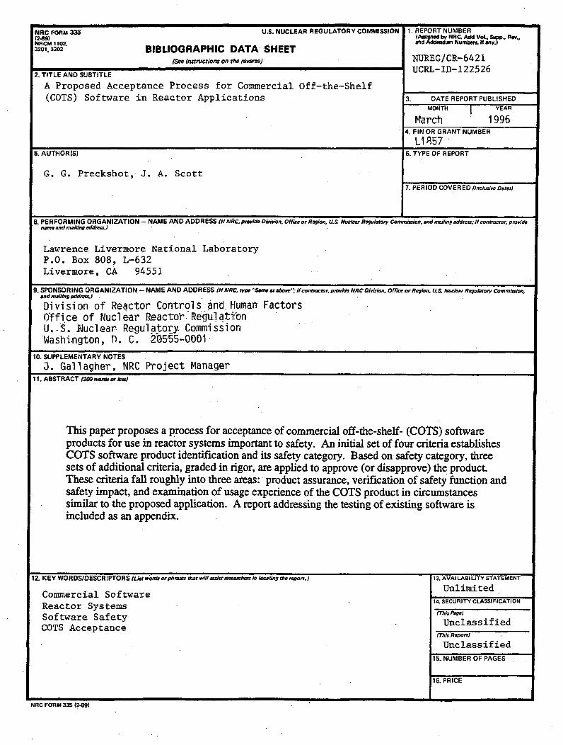
NRC FORM 335 U.S. NUCLEAR REGULATORY COMMISSION 1. REPORT NUMBER(2-89) (AuslPed by NRC. Add Vol., Supp., Rev.,NRCM 1102, and Addendum Numbemi If any.3201,3202 BIBLIOGRAPHIC DATA SHEET
(See instructions on the revw) NUREG/CR-6421
2. TITLE AND SUBTITLE UCRL-ID-122526
A Proposed Acceptance Process for Commercial Off-the-Shelf
(COTS) Software in Reactor Applications 3. DATE REPORT PUBLISHEDMONTH j YEAR
March 19964. FIN OR GRANT NUMBER
L18575. AUTHOR(S) 6. TYPE OF REPORT
G. G. Preckshot, J. A. Scott7. PERIOD COVERED linclusive Dates)
8. PERFORMING ORGANIZATION - NAME AND ADDRESS (If NRC, provide Division, OfficeorRegion, U.S NVuclear Regulatory Commission, and mailing address; If contractor, providename and mailing address)
Lawrence Livermore N~ational LaboratoryP.O. Box 808, L-632Livermore, CA 94551
9. SPONSORING ORGANIZATION - NAME AND ADDRESS (If NRC. *vpe 'Same as at e", if contractor, provide NRC Division. Office or RegIon, U.S Nuclear Regulatory Commission.9. SPONSO R ING ORGAN IZATI ON -- NAM E AND ADDR ESS Oif NRC, type "Seine as above"; if contractor, provide NRC Division, Office or Region, Q&- Nuclear Regulatory Commoission,
and mailing addes)s..
Division of Reactor Controls and Human: FactorsOffice of Nuclear Reactor- Regulat-.-onU.-$. Nuclear Regulatory CommissionWashi.ngton, T. C. 2.05-55-0001
10. SUPPLEMENTARY NOTES
J. Gallagher, NRC Project Manager11. ABSTRACT (2o wafor e1m)
This paper proposes a process for acceptance of commercial off-the-shelf- (COTS) softwareproducts for use in reactor systems important to safety. An initial set of four criteria establishesCOTS software product identification and its safety category. Based on safety category, threesets of additional criteria, graded in rigor, are applied to approve (or disapprove) the product.These criteria fall roughly into three areas: product assurance, verification of safety function andsafety impact, and examination of usage experience of the COTS product in circumstancessimilar to the proposed application. A report addressing the testing of existing software isincluded as an appendix.
12. KEY WORDS/DESCR!PTORS (List wowd orphrows that will assist researches In locating the report.) 13. AVAI LABI LITY STATEMENT
Commercial Software UnlimitedReactor Systems 14. SECURITY CLASSIFICATION
Software Safety (This Paee
COTS Acceptance Unclassified(This Report)
Unclassified15. NUMBER OF PAGES
16. PRICE
NRC FORM 335 (2-89)

Federal Recycling Program

qNw
UNITED STATESNUCLEAR REGULATORY COMMISSION
WASHINGTON, DC 20555-0001
SPECIAL FOURTH-CLASS MAILPOSTAGE AND FEES PAID
USNRCPERMIT NO. G-67
OFFICIAL BUSINESSPENALTY FOR PRIVATE USE, $300