nureg/ia-0140, 'developmental assessment of … of the low mass-flux groeneveld chf look-up...
TRANSCRIPT
NUREG/IA-0140
InternationalAgreement Report
Developmental Assessment ofRELAP5/MOD3.1 withSeparate-Effect and Integral TestExperiments: Model Changesand OptionsPrepared byG. Th. Analytis
Laboratory for Thermal HydraulicsPaul Scherrer InstituteCH-5232 Villigen PSISwitzerland
Office of Nuclear Regulatory ResearchU.S. Nuclear Regulatory CommissionWashington, DC 20555-0001
October 1998
Prepared as part ofThe Agreement on Research Participation and Technical Exchangeunder the International Code Application and Maintenance Program (CAMP)
Published byU.S. Nuclear Regulatory Commission

AVAILABILITY NOTICE
Availability of Reference Materials Cited in NRC Publications
NRC publications in the NUREG series, NRC regu-lations, and Title 10, Energy, of the Code of FederalRegulations, may be purchased from one of the fol-lowing sources:
1. The Superintendent of DocumentsU.S. Government Printing OfficeRO. Box 37082Washington, DC 20402-9328<http://www.access.gpo.gov/sudocs>202-512-1800
2. The National Technical Information ServiceSpringfield, VA 22181-0002<http:I/www.ntis.gov/ordemow>703-487-4650
The NUREG series comprises (1) technical and ad-ministrative reports, including those prepared forInternational agreements, (2) brochures, (3) pro-ceedings ofconferences and workshops, (4) adju-dications and other Issuances of the Commissionand Atomic Safety and Ucensing Boards, and(5) books.
A single copy of each NRC draft report is availablefree, to the extent of supply, upon written requestas follows:
Address: Office of the Chief Information OfficerReproduction and Distribution
Services SectionU.S. Nuclear Regulatory CommissionWashington, DC 20555-0001
E-mail: <[email protected]>Facsimile: 301-415-2289
A portion of NRC regulatory and technical informa-tion is available at NRC's World Wide Web site:
<http://www.nrc.gov>
All NRC documents released to the public are avail-able for Inspection or copying for a fee, in paper,microfiche, or, in some cases, diskette, from thePublic Document Room (PDR):
NRC Public Document Room2121 L Street, N.W., Lower LevelWashington, DC 20555-0001<http://www.nrc.gov/NRC/PDR/pdrl .htm>1-800-397-4209 or locally 202-634-3273
Microfiche of most NRC documents made publiclyavailable since January 1981 may be found in theLocal Public Document Rooms (LPDRs) located inthe vicinity of nuclear power plants. The locationsof the LPDRs may be obtained from the PDR (seeprevious paragraph) or through:
<http://www.nrc.gov/NRC/NUREGS/SR1350N9/lpdr/html>
Publicly released documents include, to name afew, NUREG-sedes reports; Federal Register no-tices; applicant, licensee, and vendor documentsand correspondence; NRC correspondence andinternal memoranda; bulletins and information no-tices; inspection and investigation reports; licens-ee event reports; and Commission papers andtheir attachments.
Documents available from public and special tech-nical libraries include all open literature items, suchas books, journal articles, and transactions, Feder-al Register notices, Federal and State legislation,and congressional reports. Such documents astheses, dissertations, foreign reports and transla-tions, and non-NRC conference proceedings maybe purchased from their sponsoring organization.
Copies of Industry codes and standards used in asubstantive manner In the NRC regulatory processare maintained at the NRC Library, Two White FlintvNorth, 11545 Rockville Pike, Rockville, MD20852-2738. These standards are available in thelibrary for reference use by the public. Codes andstandards are usually copyrighted and may bepurchased from the originating organization or, ifthey are American National Standards, from-
American National Standards Institute11 West 42nd StreetNew York, NY 10036-8002<http://www.ansi.org>212-842-4900
DISCLAIMERThis report was prepared wider an irtearronal cooperativeagreemera for the echarig of techrka kdomwalon Neithetho Urfd St~ts Goverrmait nor any agency thereo, nor anysof the emp~loes, make any warrarity expressed or imptedor assmes anyi legal 11ab*Ut or responsibifty for arry twd
perty's use, or fhe resudts of such use, of any hbifto appa-rab^J, product or process dbdosed In this report or represefttha fts use by such turd party would riot infrte privatelycavne rkjht
NUREG/IA-0140
InternationalAgreement Report
Developmental Assessment ofRELAP5/MOD3.1 withSeparate-Effect and Integral TestExperiments: Model Changesand OptionsPrepared byG. Th. Analytis
Laboratory for Thermal HydraulicsPaul Scherrer InstituteCH-5232 Villigen PSISwitzerland
Office of Nuclear Regulatory ResearchU.S. Nuclear Regulatory CommissionWashington, DC 20555-0001
October 1998
Prepared as part ofThe Agreement on Research Participation and Technical Exchangeunder the International Code Application and Maintenance Program (CAMP)
Published byU.S. Nuclear Regulatory Commission

ABSTRACT
A summary of modifications and options introduced in RELAP5/MOD3.1(R5M3.1) is presented and is shown that the predicting capabilities of the mod-ified version of the code are greatly improved, while the general philosophy wefollowed in arriving at these modifications is also outlined. These changes whichare the same ones we implemented in the past in the version 7j of the code, include2 different heat transfer packages (one of them activated during reflooding), mod-ification of the low mass-flux Groeneveld CHF look-up table and of the dispersedflow interfacial area (and shear) as well as of the criterion for transition into andout from this regime, almost complete elimination of the under-relaxation schemesof the interfacial closure coefficients etc. The modified R5M3.1 code is assessedagainst a number of separate-effect and integral test experiments and in contrastto the frozen version, is shown to result in physically sound predictions which aremuch closer to the measurements, while almost all the predicted variables are freeof unphysical spurious oscillations. The modifications introduced solve a numberof problems associated with the frozen version of the code and result in a versionwhich can be confidently used both for SB-LOCA and LB-LOCA analyses.
iii

CONTENTS
1 INTRODUCTION ............................................... 1
2 MODIFICATIONS AND OPTIONS IN R5M3.I ....................... 5
3 ASSESSMENT OF THE MODIFIED CODE AND COMPARISON
WITH THE FROZEN VERSION .................................. 22
3.1 The NEPTUN and FLECHT-SEASET bottom flooding tests .......... 22
3.2 The THTF 3.08.6C test ...................................... 24
3.3 The LOFT LP-LB test .................................. 25
3.4 A hypothetical LB-LOCA in a two-loop 1130 MWth commercial PWR.. 26
3.5 The LOBI SB-LOCA BL34 test ............................... 26
4 CONCLUSIONS AND DISCUSSIONS ............................. 27
V

1 INTRODUCTION
During the last decade, under the ICAP (International Code Assessment and Ap-plications Program) and lately the CAMP (Code Assessment and MaintenanceProgram), there has been an International effort directed towards assessing andimproving different thermal-hydraulics reactor transient analysis codes. The aimof this effort is to end up with transient analysis computer codes for PWRs andBWRs (and also for advanced reactors) which can be used for licensing as well asfor analyzing different reactor transients. In this effort, the data from a large num-ber of separate-effect and integral test experiments has been utilized for assessingeither individual physical models in these codes, or the performance of the codesas integral entities. Clearly, in many situations of interest, the fine details of aphysical model are not very important to the over-all predicting capability of thecode, and the latter may be determined by other factors like node size, interpola-tion schemes, finite-differencing scheme etc; as a matter of fact, the line separatingthe physically faithful and detailed modeling from the practically useful one withinthe framework of a code is always rather vague and mostly difficult to define andquantify. Nevertheless, the employment of physically sound and realistic models isa necessary requirement for having a physically robust code (as opposed to nu-merically robust; though, the two items can sometimes be closely inter-related!) which can be technically defended. Though, the improvement efforts should notonly be restricted to the implementation of physically defendable models, but alsoto other "numerics" related areas like interpolation schemes, old-time averaging(under-relaxation) used to smooth the interfacial closure coefficients between twosuccessive time-steps etc.
During the last few years, extensive assessment [1-4] of the transient thermalhydraulics code RELAP5/MOD3 versions 5m5 and 7j [5,6] (henceforth to bereferred to as R5M3) has been pursued and a number of deficiencies (particularlyin relation to physical modeling) and problem areas have been identified, the moststriking one being the inability of the code to even remotely capture the physicsof reflooding [1,2,4], something which makes the code totally inadequate for LB-LOCA calculations. The main reason for this is the inappropriateness of the post-CHF wall-to-liquid heat transfer logic of the code; in fact, we have shown in thepast [1,2] that this logic can be problematic, independently of whether the physicalprocess is reflooding or not. Saying this, we should clearly state at this point thatsince the policy of the NRC has been during the last few years that R5M3 shouldnot be used for LB-LOCAs (TRAC-PF1 was supposed to be the code for analyzingthese transients), it is inevitable that neither a systematic effort was spent by thecode developers to implement in the code models which would be appropriate forreflooding, nor extensive studies and assessments of the present capabilities of thecode in this area were undertaken. Nevertheless, a number of CAMP membercountries using the code have been rightly insisting that R5M3 should be able tomodel reflooding and that one should be able to use it for analyzing hypotheticalLB-LOCA transients.
I
As a result of this situation, a broad developmental program has been under-
taken, and a number of improvements covering a rather extensive area have been
made [1,2]. Here, we should add that a number of workers from different countrieshave also demonstrated that as far as LB-LOCAs are concerned, R5M3 is suffer-
ing from a number of shortcomings, the result of this being that they abandoned
using the code in favour of RELAP5/MOD2.5, whose ability to model reflood-
ing although by no means perfect, was nevertheless much better than the one of
R5M3. This is clearly not an acceptable situation since one could actually try
to improve R5M3 by implementing models which would enhance and improve the
capabilities of the code in modeling a much wider range of transients rather than
reversing back to its predecessor which, admittedly, did perform better than R5M3
for some cases. Though, it is now becoming clear that before moving into applica-
tions of the code to advanced reactors, a number of problems with which the code
is plagued should be tackled and, if possible, resolved in a clear and satisfactory
manner. Although as far as advanced reactors are concerned, these problems are
mainly related to modeling heat transfer in the presence of non-condensible rather
than the post-CHF heat transfer, ideally, one should have a code whose predictionsare reliable independently of whether one analyzes transients in conventional or
advanced reactors.
The improvement of the predicting capabilities of a code (which, let us notforget, is supposed to be able to capture a wide variety of phenomena in a verycomplex system) and the subsequent assessment of a resulting "new version" is
not at all a straight-forward or easy task and a systematic and coordinated effortis required if this is to be accomplished in an efficient and scientifically defendable
fashion. In particular, it is not only the individual physical models that have
to be sound and realistic, but the way they are connected with each other overtransition regimes must be consistent and free of discontinuities which, in turn,
may excite unwanted oscillations which can adversely affect the final predictions,to the extent that they are no longer representative of the physical models in the
code. Hence, there is a host of different problems which have to be addressed and
resolved during the development and assessment of a particular code version, some
of them (and sometimes, most of them) not being directly related to the way that
the code is attempting to model a particular physical process. As far as R5M3.1 is
concerned, our task is simplified and our assessment efforts (at least as far as the
deficiencies in the heat-transfer related models are concerned) are actually guided
by the corresponding efforts we made for improving the version 7j of the code, the
reason being that no physical models have been changed between the two versions.
In our general effort to improve R5M3, the following steps were taken when
we were developing and testing our modifications:
(a) Assess specific models of the fixed code version by analyzing rather simpleseparate-effect tests in which these models are dominant. As an example, a
boil-off test under no-flow conditions would reveal the appropriateness (or
not) of the bubbly/slug interfacial shear model while a bundle reflooding
2
experiment would test the appropriateness of the post-CHF wall-to-liquidheat transfer, dispersed flow interfacial shear (and area) etc. Though, inthe latter example, the task is really more complicated since there will be anumber of competing effects influencing the final code predictions of interest.
(b) Whenever there are large deviations from the measurements (eg in the rodsurface temperature (RST) histories) and it is clear that the code predictionsare qualitatively wrong, try to understand the reason(s) that this is hap-pening and propose a solution to the problem. We believe that should thisbe the case, it makes no sense whatsoever to try to use the code for a reactorcalculation; any code predictions would be of no use and any conclusionsdrawn would be unsubstantiated. Furthermore, it could be that althoughcertain variables are "correctly" predicted, this is clearly coincidental andthere are probably large deviations in other variables. Generally, the reasonof the deviations may be due to the inappropriateness of a specific physicalmodel but it is also possible (and this is usually the case) that the deviationsare due to more than one reasons; in this case, a greater effort is requiredto understand and resolve the problem and the action to be taken may bemore complex.
(c) Having changed the specific model (or models), re-analyze with the new ver-sion the series of simple tests and note any resulting improvement. Subse-quently, perform with this version integral test calculations (eg LOFT) forwhich data exists as well as possible hypothetical transients (eg different LB-LOCAs) and examine the code's performance by comparing the predictionsof the new and the fixed version. In most cases, improved code performancefor a separate-effect test will, one way or an other, also show up in a largesystem calculation.
(d) Should additional modifications in relation to other physical models are in-troduced and yet a different code version is created, it is possible that thegood predictions of the integral test transients evaluated with the previouscode version are adversely affected by the new changes. Hence, the previ-ously evaluated transients should be re-analyzed with the latest code version.Should the new model changes are physical and realistic and not "contradic-tory" to the other models, the latest code version should also produce resultsequally good (ideally, even better) as the previous one and this has indeedbeen the case for almost all modifications we have introduced in the code.Should this not be the case, one should tr, to understand the reason (orreasons) why this is not so and try to correct it; this is a rather complicatedbut inescapable step in our approach. In any case, one should certainly notfall into the trap of avoiding making a physically sound change just becausethe results of other "good" calculations are affected: Sooner or later, onewill have to pay the penalty of such an approach.
(e) In our effort of improving the code, one may frequently come across problemsand difficulties arising not from the actual physical models, but from the
3
interpolations used between two different correlations, the error bounds set
for advancing the solution, the old-time averaging schemes of the interfacial
constitutive coefficients etc. These are the most difficult and challengingproblems to deal with and sometimes they even require some compromise
between the physics and the "numerics". Though, we have noted a number of
cases in which, for example, the implementation of a more physically sound
model may result in suppression of unphysical oscillations.
One must certainly admit that the aforementioned procedure can be rather
complex and time-consuming. Though, we believe that it is the only realistic path
to follow if one is to end up with a code which is reliable, physically robust, easily
defendable and can predict complicated transients. Additionally, we strongly be-
lieve that code users reporting on generic code deficiencies, should be in a position
to further investigate the reason(s) for it and if possible, suggest ways of resolving
the problems. This may not always be a straight-forward task since a particular
code deficiency may require changes in a number of models; this brings us back to
the above tedious step-by-step procedure.
It is the aim of this work to show that with some relatively modest effort and
by following the aforementioned approach which we have been closely following in
the past, one can successfully solve a number of important problems associated
with the code, most of which are of a rather generic nature, have been frequently
reported in the literature, are the main reasons against employing R5M3 for LB-LOCA calculations and, most important, are shared by all versions of R5M3.
In this work, we shall summarize the model changes and code modifications
we implemented in R5M3.1 (henceforth to be referred to as frozen version), trying
at the same time to explain the reason(s) why it was necessary to make them.Most of these reasons we have already discussed in the past and although when-
ever possible, we shall refer the reader to the literature, since we want to make this
work self-contained, we shall spend some time discussing the different problems
and model-changes to some detail. Most of the modifications to be reported here
are identical to the ones we have implemented in the version 7j of R5M3 and have
been extensively discussed in a number of previous works and CAMP presenta-
tions; though, there is a small number of new ones which are not actually related
to new physical models. These changes which we shall discuss in some detail in
section 2, include the implementation of two different wall-to-liquid heat transfer
packages and complete removal of the package of the frozen version (which has
been shown to be unphysical and problematic, due to the peculiar behaviour of
the Chen transition/film boiling heat transfer correlation as a function of the total
mass-flux), modification of the low mass-flux limit of the Groeneveld CHF look-up table, modification of the minimum allowed droplet diameter (and hence, the
interfacial shear) in dispersed flow and the criterion for transition to this regime,
re-activation of the modified Bestion bubbly/slug interfacial shear correlation for
low pressures and almost complete elimination of the under-relaxation schemes
of the interfacial closure coefficients. In particular, a special wall-to-liquid heat
4
transfer package is implemented and activated when reflooding is being modelled.In this package, the wall-to-liquid heat transfer coefficient is expressed as a func-tion of the distance from the bottom QF, and as an option, the heat transferas a function of the distance from the top QF can also be computed, resultingin a downwards propagating top QF. Though, the constants appearing in thislatter option are still not set with confidence, awaiting comparison with experi-mental data. In section 3, we shall compare the predictions of the modified codewith the ones of the frozen version as well as with measurements from a numberof separate-effect and integral test experiments and wherever possible, we shallbriefly comment on the origin of the differences in predictions between the twocode versions. The tests we shall be analyzing both with the frozen and modifiedversions of the code are bottom-flooding experiments in the NEPTUN half-lengthheater rod bundle at PSI and at the FLECHT-SEASET heater full-length bundle,the Oak Ridge THTF low power film boiling experiment Nr. 3.08.6C, the LOFTLP-LB-1 test (for which case we shall also demonstrate the effect of changing theannular flow interfacial shear model everywhere except the core) and the LOBISB-LOCA BL34 experiment. Additionally, for the sake of completeness, we shallanalyze a hypothetical LB-LOCA in a commercial two-loop 1130 MWth PWR.
Although this work represents a rather extensive summary of work pursuedduring the last 3 - 4 years, we are in no way claiming that all problems associatedwith this code are solved, that our proposed solutions are "unique" or that thereare no other areas than the ones addressed in this work that attention is required.Additionally, a much wider assessment basis of our modified version of the code isneeded; though, the physically sound and consistent results obtained up to now forthe cases analyzed show that provided the right physical models are implementedin the code, R5M3 can confidently be used both for LB-LOCA and SB-LOCA anal-yses. Hence, with the exception of perhaps the ability to model with some codesmore geometrical details than with others due to eg their 3-dimensional capabili-ties (capabilities which one could in principle dispute due to the large volumes oneusually employs for the 3-dimensional components), the classification of differentcodes into "SB-LOCA codes" and "LB-LOCA codes" is, to say the least, concep-tually erroneous and misleading and should be abandoned: The actual physicalmodels are invariant to the code in which they are implemented andapart from possible geometrical limitations, all codes should be able tomodel the same phenomena and transients. Finally, we shall conclude insection 4 with some recommendations.
2 MODIFICATIONS AND OPTIONS IN R5M3.1
We shall now very briefly outline the code modifications and model changes wehave implemented in R5M3.1; most of them are identical to the ones we haveimplemented in the version 7j of the code. These are:
5
(a) The modified Bestion interfacial shear correlation for bubbly/slug flow was
re-activated and used for pressures less than 10 bar. It reads [7-9]
6 65 a (1 - a) 3 pg (CV - CoV)2 (2.1)
DH
where p. and DH are the steam density and hydraulic diameter, respectively,
while the value of the distribution parameter C. is set equal to 1.2. For pres-
sures greater than 20 bar, the EPRI interfacial shear correlation [5] already
in the code is used, and a linear interpolation is used between these two pres-
sures. There is a number of reasons for re-activating the modified Bestion
correlation, one of them being that as has already been shown in Ref. 5,
it results in very good predictions for low pressures. Additionally, recentwork has shown that the highly complex EPRI correlation, due to its depen-
dence on a large number of local variables which are usually oscillating in
a transient calculation, may induce a number of undesirable side-problems,one of them being an unacceptably high mass-error. Hence, although the
EPRI correlation (which is only one part of the very complex bubbly/sluginterfacial shear package of the frozen version of RSM3), due to the fact that
it is actually a fit to a large number of data points, is bound to result, ingeneral, in better predictions than other correlations, we would generally
recommend employing simpler bubbly/slug interfacial shear correlations like
the aforementioned modified Bestion correlation for bundles and for pipes,
the one used in codes like TRAC-BF1 [101 (see item (k) below).
(b) In order to avoid vapour de-superheating (the interfacial heat transfer fromthe vapour to the droplets is proportional to the interfacial area per unit
volume Sd, and hence, inversely proportional to the "average" droplet di-
ameter D,), the average droplet diameter D'o defined via the Weber number
(We) was increased in R5M3 by the code developers by increasing (We) to
12 (in RELAP5/MOD2.5, it had the value of 3). Additionally, the minimum
allowed droplet diameter D' in the post-dryout regime is defined (ad-hoc)
as a function of the pressure p as follows:
D'm = 0.0025 for _ 0.025,
D' = 0.0025 -
4.444 (0.0025 - 0.0002) (3 - 0.025), (2.2)for 0.025 < Pi < 0.25,
D' = 0.0002 for P > 0.25
P= p/p,,., p is the pressure and p, is the critical pressure. The final averagedroplet diameter Do used is defined by
D0 = min {DH, max (D',D)} (2.3)
where D' is defined by eq.(2.2) (with (We) = 12). Hence, as can be seenfrom eq. (2.3), for p < 5.4 bar, the average droplet diameter is not allowed
6
to be less than 0.0025 m. Subsequently, the droplet interfacial area per unitvolume Sd, is defined by [5,6]
Sdr - 3.6 (1 (2.4)Do
In R5M3, the interfacial shear is proportional to Sdr and since the dropletsare large (small interfacial area), in a number of situations, the droplets can-not be "lifted" by the vapour. Hence, we re-set the Weber number to 3 andassumed a minimum average droplet diameter of 0.0015m. In actual fact, theminimum average droplet diameter observed during the FLECHT-SEASETtests was in the range of 0.0008 m. Though, there is no explicit spacer modelin the code (and spacers do certainly play a very important role in the amountof liquid carry-over in bundles particularly during low-flooding rate bottomflooding). Furthermore, we believe that there are geometry-effects contribut-ing to the lower liquid carry-over in rod bundles (as compared to tubes) andthese effects cannot be qualified. Finally, in a 2-fluid model code one can-not "rigorously" define an average droplet diameter since there is only oneliquid field. Consequently, assuming a smaller minimum average droplet di-ameter would lead (through the resulting higher interfacial shear) in a liquidcarry-over higher than the measurements show. Hence, the assumed value of0.0015m is based on a compromise and engineering judgement rather thanon a rigorous argument.
(c) The logic for selecting the pre- or the post-CHF interfacial closure laws inR5M3 are as follows: One defines
P > 1 (2.5)
whereP = max (0, min (1, P' (0.4 - aB)10)). (2.6a)
Now P' is defined by
P1 = min (1, Pwi,nd Tgs) (2.6b)
where
Pid = 0.06666667 for P:< 0.025,
Pwind = 0.016666667 for P > 0.25, j (2.6c)
Pui•nd = Interp. for 0.025 < P < 0.25,
andTg=T T, - 1. (2.6d)
OB is the void fraction for transition from bubbly to slug flow and T. and T.are the vapour and saturation temperatures, respectively. If (2.5) is satisfied,the code selects the post-dry out closure laws. The reason for this "indirect"
7
selection logic is that the interfacial closure laws subroutines are not actually"communicating" with the ones for the wall heat transfer and one would like
to have some consistency between the two (which, by the aforementionedindirect procedure, is not always possible). We found that the definition of
P' given by (2.6b) with Pind given by (2.6c) is too restrictive. Hence, wemodified equation (2.6b) to read (as it was defined in RELAPS/MOD2.5
[8])PI = 1.0000454 (1 - e-0 Tgs) (2.7a)
where now (as we modified it in the past in RELAP5/MOD2.5 [8]),if the component in question is a bundle,
Tga = Tg - T. - 29 (2.7b)
otherwise, T.o is given by eq. (2.6d). This modification has a surprisinglylarge effect on a number of important predictions, and this can be easily
understood if one realizes that it changes the "points" of transition from wetto dry-wall interfacial shear correlations (and vice versa), which are largelydifferent in magnitude. Here, we should say that the selection of the value 29in the above equation was made based on inspection of a number of predictedvoid fraction profiles during reflooding which with the original formulation,were exhibiting discontinuities near the quench front (QF) as in the case of
RELAP5/MOD2.5 [8]. Conceptually, decrease (resp. increase) of this valueresults in employing the post-CHF interfacial closure laws at a lower (resp.
higher) vapour temperature.
(d) We have completely removed the post-CHF wall-to-liquid heat transfer pack-age of the code and in its place, we implemented two different packages, one
when the physical process is reflooding and the other when it is not; hence,we reversed back to the RELAP5/MOD2 philosophy, but the packages we
implemented are different to the ones in RELAP5/MOD2. The reasons forwhich we believe that the post-CHF heat transfer package of RSM3 is inap-
propriate and physically erroneous have already been extensively discussedin a series of previous works [1-31; here, we shall briefly outline the logic of
this package.
If the wall temperature T. is greater than T. + 75 and less than T, + 600, thewall-to-liquid heat transfer coefficient is computed in the code as the maxi-
mum between the one given by the Chen transition/film boiling correlation
(which has the form qcHF exp(-1.34164 min (15, V/T, -To ) 0) / (TfI- T-),where qCHF is the critical heat flux and 0 = E(IGI, a) a complicated func-tion of a and the total mass-flux IGI ), and the modified Bromley correlation
(supplemented by a void-fraction dependence), while if Tw > To + 600,is computed by the latter. As we have previously discussed on a numberof different occasions [1,3], this approach is problematic, due to the factthat the Chen transition/film boiling correlation (which is a function of the
a
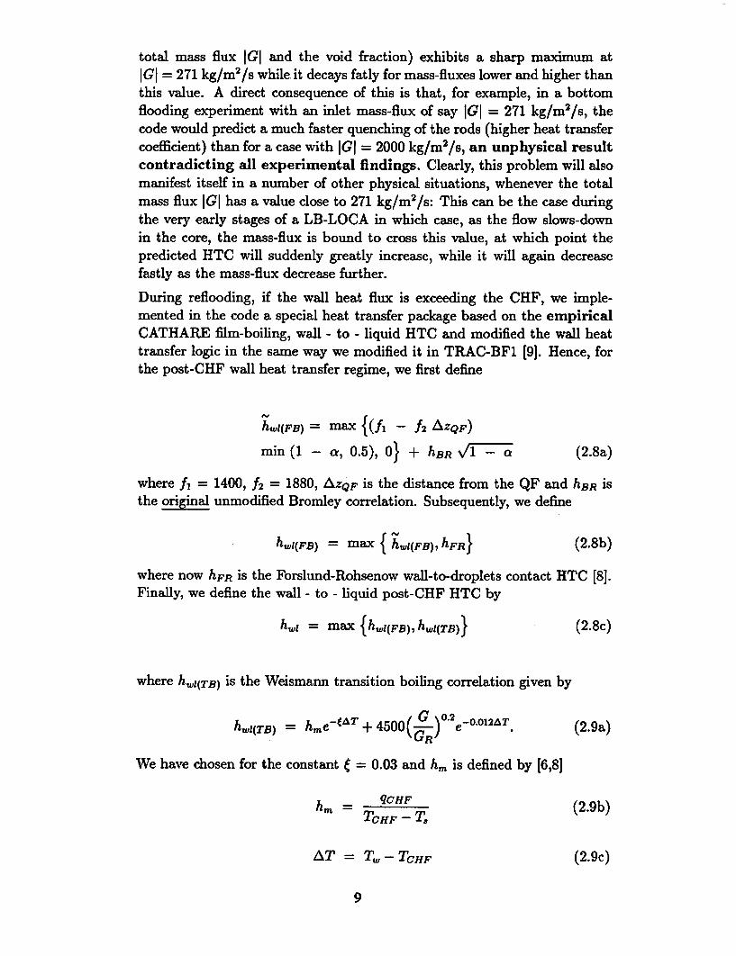
total mass flux IGI and the void fraction) exhibits a sharp maximum atIGI = 271 kg/m 2 /s while, it decays fatly for mass-fluxes lower and higher thanthis value. A direct consequence of this is that, for example, in a bottomflooding experiment with an inlet mass-flux of say IGI = 271 kg/m 2 /s, thecode would predict a much faster quenching of the rods (higher heat transfercoefficient) than for a case with IGI = 2000 kg/m 2/s, an unphysical resultcontradicting all experimental findings. Clearly, this problem will alsomanifest itself in a number of other physical situations, whenever the totalmass flux IGI has a value close to 271 kg/m 2/s: This can be the case duringthe very early stages of a LB-LOCA in which case, as the flow slows-downin the core, the mass-flux is bound to cross this value, at which point thepredicted HTC will suddenly greatly increase, while it will again decreasefastly as the mass-flux decrease further.
During reflooding, if the wall heat flux is exceeding the CHF, we imple-mented in the code a special heat transfer package based on the empiricalCATHARE film-boiling, wall - to - liquid HTC and modified the wall heattransfer logic in the same way we modified it in TRAC-BF1 [9]. Hence, forthe post-CHF wall heat transfer regime, we first define
htLi(FB) =Max {(fh - f2 AZQF)
min (1 - a, 0.5), 0} + hBRVr1 -- a (2.8a)
where f, = 1400, f2 = 1880, AZQ•F is the distance from the QF and hBR isthe original unmodified Bromley correlation. Subsequently, we define
hw1(FB) = max {h.1(FB) 7 hFR} (2.8b)
where now hFR is the Forslund-Rohsenow wall-to-droplets contact HTC [8].Finally, we define the wall - to - liquid post-CHF HTC by
h,= maxc {hwq(FB), hwi(TB)} (2.8c)
where hwi(TB) is the Weismann transition boiling correlation given by
h1 01(TB) = hme--AT + 4 500(G )_2&e.12AT. (2.9a)
We have chosen for the constant • = 0.03 and h.. is defined by [6,8]
hm - qCHF (2.9b)TCHF - T,
AT =T - TCHF (2.9c)
9
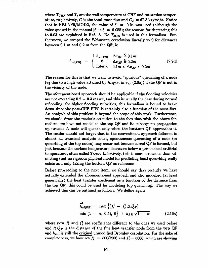
where TCHF and To are the wall temperature at CHF and saturation temper-ature, respectively, G is the total mass-flux and GR = 67.8 kg/m 2 /s. Notice
that in RELAP5/MOD2, the value of ý = 0.04 was used (although the
value quoted in the manual [6] is ý = 0.055); the reasons for decreasing this
to 0.03 are explained in Ref. 8. No TMIN is used in this formalism. Fur-
thermore, we ramped the Weismann correlation linearly to 0 for distances
between 0.1 m and 0.2 m from the QF, ie
hwl(TB) AZQF < 0.1mh,1(TB) = 0 AZQF > 0.2m (2.9d)
Interp. 0.lm < AZQF < 0.2m.
The reason for this is that we want to avoid "spurious" quenching of a node(eg due to a high value attained by h,,(TB) in eq. (2.9a)) if the QF is not in
thc vicinity of the node.
The aforementioned approach should be applicable if the flooding velocities
are not exceeding 0.2 - 0.3 m/sec, and this is usually the case during normalreflooding; for higher flooding velocities, this formalism is bound to brake
down since the post-CHF HTC is certainly also a function of the mass-flux.An analysis of this problem is beyond the scope of this work. Furthermore,we should draw the reader's attention to the fact that with the above for-
malism, we have not modelled the top QF and its subsequent propagationup-stream: A node will quench only when the bottom QF approaches it.
The reader should not forget that in the conventional approach followed inalmost all transient analysis codes, spontaneous quenching of a node (or
quenching of the top nodes) may occur not because a real QF is formed, but
just because the surface temperature decreases below a pre-defined artificialtemperature, often called TMIN. Effectively, this is more erroneous than ad-
mitting that no rigorous physical model for predicting local quenching reallyexists and only taking the bottom QF as reference.
Before proceeding to the next item, we should say that recently we have
actually extended the aforementioned approach and also modelled (at leastgenerically) the heat transfer coefficient as a function of the distance from
the top QF; this could be used for modeling top quenching. The way we
achieved this can be outlined as follows: We define again
hwi(FB) =max {(fI - A~ LZQF)
min (1 - 0.5), 0} + hBR vF--Q (2.10a)
where now f' and ft are coefficients different to the ones we used before
and Azt, is the distance of the fine heat transfer node from the top QF
and hER is still the original unmodified Bromley correlation. For the sake ofcompleteness, we have set ft = 500(200) and f2 = 5000, which are showing
10
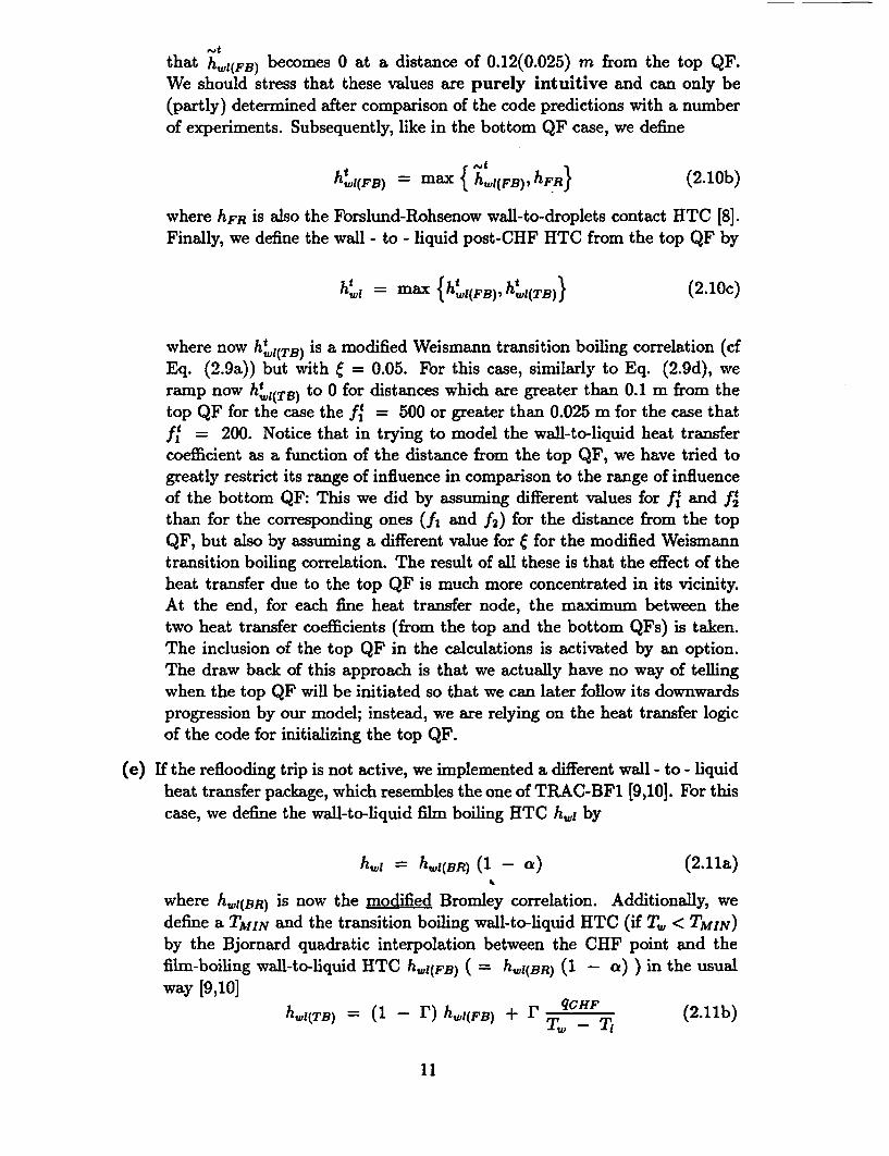
that hwi(FB) becomes 0 at a distance of 0.12(0.025) m from the top QF.We should stress that these values are purely intuitive and can only be(partly) determined after comparison of the code predictions with a numberof experiments. Subsequently, like in the bottom QF case, we define
h~t1 (FB) = max { hwl(FB),hFR} (2.10b)
where hFR is also the Forslund-Rohsenow wall-to-droplets contact HTC [8].Finally, we define the wall - to - liquid post-CHF HTC from the top QF by
ht, = max {h,(Bh,(tB (2.10c)
where now hli(TB) is a modified Weismann transition boiling correlation (cfEq. (2.9a)) but with • = 0.05. For this case, similarly to Eq. (2.9d), weramp now htw(TB) to 0 for distances which are greater than 0.1 m from thetop QF for the case the ft = 500 or greater than 0.025 m for the case thatft = 200. Notice that in trying to model the wall-to-liquid heat transfercoefficient as a function of the distance from the top QF, we have tried togreatly restrict its range of influence in comparison to the range of influenceof the bottom QF: This we did by assuming different values for R and ftthan for the corresponding ones (f, and f2) for the distance from the topQF, but also by assuming a different value for e for the modified Weismanntransition boiling correlation. The result of all these is that the effect of theheat transfer due to the top QF is much more concentrated in its vicinity.At the end, for each fine heat transfer node, the maximum between thetwo heat transfer coefficients (from the top and the bottom QFs) is taken.The inclusion of the top QF in the calculations is activated by an option.The draw back of this approach is that we actually have no way of tellingwhen the top QF will be initiated so that we can later follow its downwardsprogression by our model; instead, we are relying on the heat transfer logicof the code for initializing the top QF.
(e) If the reflooding trip is not active, we implemented a different wall - to - liquidheat transfer package, which resembles the one of TRAC-BF1 [9,101. For thiscase, we define the wall-to-liquid film boiling HTC h,,t by
h, = hI,1(BR) (1 - a) (2.11a)
where hwl(BR) is now the modified Bromley correlation. Additionally, wedefine a TAfIN and the transition boiling wall-to-liquid HTC (if T, < TMIN)by the Bjornard quadratic interpolation between the CHF point and thefilm-boiling wall-to-liquid HTC hw,(FB) ( = hI(BR) (1 -I ) ) in the usualway [9,10]
qCHF (2.11b)hwj(TB) r)(1 -- h(FB) + I T T(
11
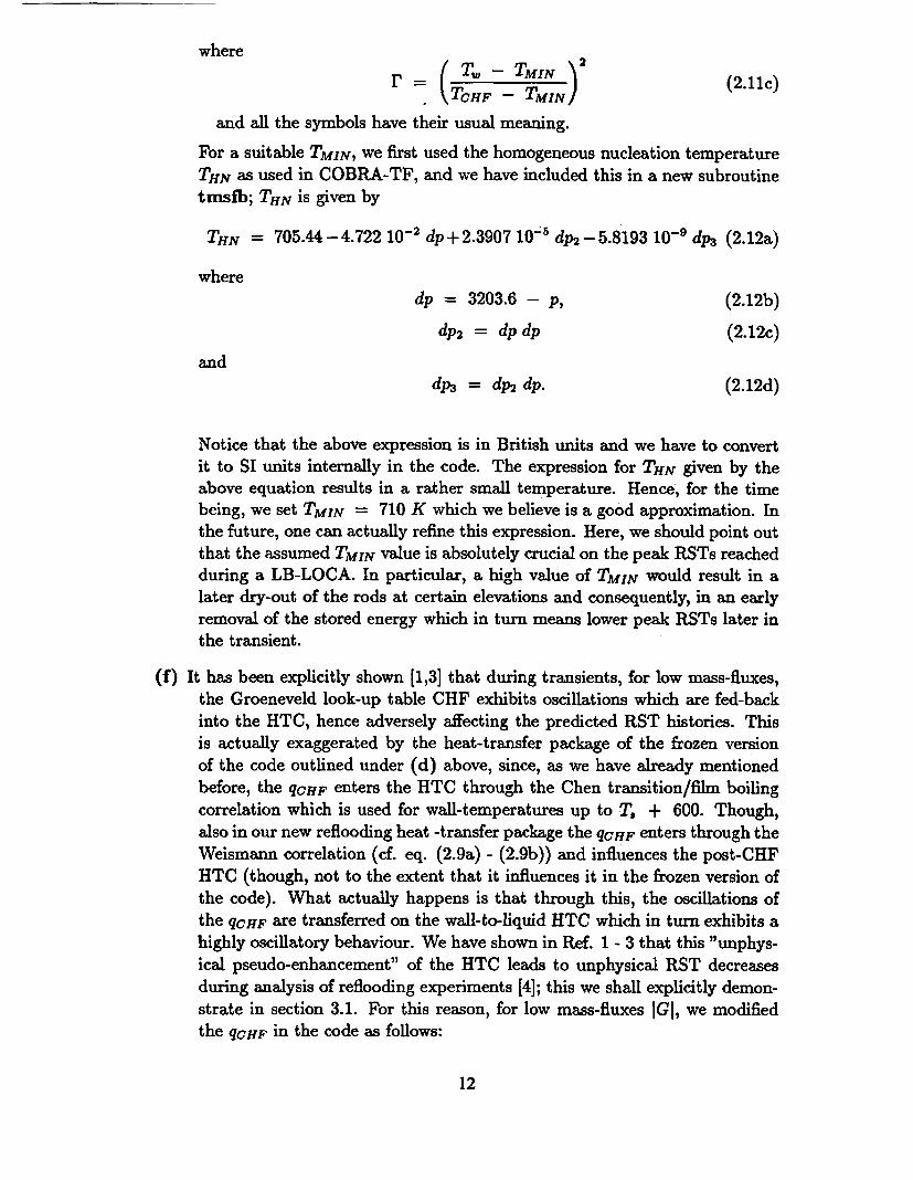
whereS= -TMIN (2.11c)
r = •TCHF - TMIN)
and all the symbols have their usual meaning.
For a suitable TMIN, we first used the homogeneous nucleation temperature
THN as used in COBRA-TF, and we have included this in a new subroutine
tmsfb; THN is given by
THN = 705.44 - 4.722 10-2 dp + 2.3907 10iý dp2 - 5.8193 10'- dp3 (2.12a)
wheredp = 3203.6 - p, (2.12b)
dp2 = dp dp (2.12c)
anddP3 = dP2 dp. (2.12d)
Notice that the above expression is in British units and we have to convert
it to SI units internally in the code. The expression for THN given by theabove equation results in a rather small temperature. Hence, for the time
being, we set TMIN = 710 K which we believe is a good approximation. In
the future, one can actually refine this expression. Here, we should point out
that the assumed TMIN value is absolutely crucial on the peak RSTs reached
during a LB-LOCA. In particular, a high value of TMIN would result in a
later dry-out of the rods at certain elevations and consequently, in an early
removal of the stored energy which in turn means lower peak RSTs later in
the transient.
(f) It has been explicitly shown [1,3] that during transients, for low mass-fluxes,
the Groeneveld look-up table CHF exhibits oscillations which are fed-back
into the HTC, hence adversely affecting the predicted RST histories. This
is actually exaggerated by the heat-transfer package of the frozen version
of the code outlined under (d) above, since, as we have already mentionedbefore, the qCHF enters the HTC through the Chen transition/film boiling
correlation which is used for wall-temperatures up to T. + 600. Though,
also in our new reflooding heat -transfer package the qCHF enters through the
Weismann correlation (cf. eq. (2.9a) - (2.9b)) and influences the post-CHF
HTC (though, not to the extent that it influences it in the frozen version of
the code). What actually happens is that through this, the oscillations of
the qCHF are transferred on the wall-to-liquid HTC which in turn exhibits a
highly oscillatory behaviour. We have shown in Ref. 1 - 3 that this "unphys-
ical pseudo-enhancement" of the HTC leads to unphysical RST decreases
during analysis of reflooding experiments [4]; this we shall explicitly demon-
strate in section 3.1. For this reason, for low mass-fluxes IGI, we modified
the qcHF in the code as follows:
12
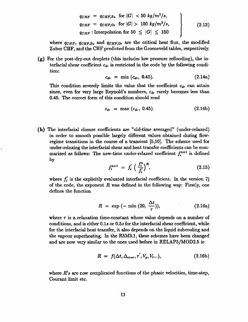
qCHF = qcHF,z. for IGI < 50 kg/M 2Is,
qCHF = qcHF,Gv for IGI > 150 kg/m 2/8, (2.13)
qcHF: Interpolation for 50 < IGI < 150
where qCHF, qCHF,Zu and qcHFG, are the critical heat flux, the modifiedZuber CHF, and the CHF predicted from the Groeneveld tables, respectively.
(g) For the post-dry-out droplets (this includes low pressure reflooding), the in-terfacial shear coefficient Cd, is restricted in the code by the following condi-tion:
cd, = min (cdr, 0.45). (2.14a)
This condition severely limits the value that the coefficient Cdv can attainsince, even for very large Reynold's numbers, cd,. rarely becomes less than0.45. The correct form of this condition should read
Cdr = max (Cd,, 0.45). (2.14b)
(h) The interfacial closure coefficients are "old-time averaged" (under-relaxed)in order to smooth possible largely different values obtained during flow-regime transitions in the course of a transient [5,10]. The scheme used forunder-relaxing the interfacial shear and heat transfer coefficients can be sum-marized as follows: The new-time under-relaxed coefficient fi+1 is definedby
by li =fi( Ai)_ (2.15)
where f is the explicitly evaluated interfacial coefficient. In the version 7jof the code, the exponent R was defined in the following way: Firstly, onedefines the function
At,R = exp (- min (20, t-)) (2.16a)
where r is a relaxation time-constant whose value depends on a number ofconditions, and is either 0.Us or 0.5s for the interfacial shear coefficient, whilefor the interfacial heat transfer, it also depends on the liquid subcooling andthe vapour superheating. In the R5M3.1, these schemes have been changedand are now very similar to the ones used before in RELAP5/MOD2.5 ie
R = f(AtAcou,,r', Vg, V1...), (2.16b)
where RMs are now complicated functions of the phasic velocities, time-step,Courant limit etc.
13
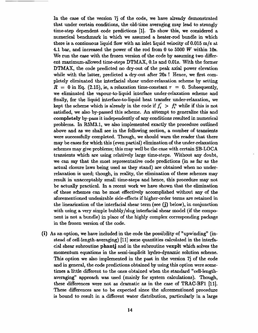
In the case of the version 7j of the code, we have already demonstratedthat under certain conditions, the old-time averaging may lead to stronglytime-step dependent code predictions [1]. To show this, we considered a
numerical benchmark in which we assumed a heater-rod bundle in which
there is a continuous liquid flow with an inlet liquid velocity of 0.015 m/s at
4.1 bar, and increased the power of the rod from 0 to 5500 W within 10s.
We run the case with the frozen version of the code by assuming two differ-
ent maximum-allowed time-steps DTMAX, 0.Us and 0.01s. With the former
DTMAX, the code predicted no dry-out of the peak axial power elevation
while with the latter, predicted a dry-out after 20s ! Hence, we first com-
pletely eliminated the interfacial shear under-relaxation scheme by setting
R = 0 in Eq. (2.15), ie, a relaxation time-constant r = 0. Subsequently,we eliminated the vapour-to-liquid interface under-relaxation scheme and
finally, for the liquid interface-to-liquid heat transfer under-relaxation, we
kept the scheme which is already in the code if f, > fi while if this is not
satisfied, we also by-passed this scheme. An attempt to generalize this andcompletely by-pass it independently of any conditions resulted in numericalproblems. In R5M3.1, we also implemented exactly the procedure outlined
above and as we shall see in the following section, a number of transientswere successfully completed. Though, we should warn the reader that theremay be cases for which this (even partial) elimination of the under-relaxationschemes may give problems; this may well be the case with certain SB-LOCAtransients which are using relatively large time-steps. Without any doubt,
we can say that the most representative code predictions (in as far as the
actual closure laws being used as they stand) are obtained when no under-relaxation is used; though, in reality, the elimination of these schemes may
result in unacceptably small time-steps and hence, this procedure may notbe actually practical. In a recent work we have shown that the eliminationof these schemes can be most effectively accomplished without any of the
aforementioned undesirable side-effects if higher-order terms are retained in
the linearization of the interfacial shear term (see (j) below), in conjunctionwith using a very simple bubbly/slug interfacial shear model (if the compo-
nent is not a bundle) in place of the highly complex corresponding package
in the frozen version of the code.
(i) As an option, we have included in the code the possibility of "upwinding" (in-
stead of cell-length-averaging) [11] some quantities calculated in the interfa-
cial shear subroutine phantj and in the subroutine vexplt which solves the
momentum equations in the semi-implicit hydro-dynamic solution scheme.
This option we also implemented in the past in the version 7j of the code
and in general, the code predictions obtained by using this option were some-times a little different to the ones obtained when the standard "cell-length-
averaging" approach was used (mainly for system calculations). Though,
these differences were not as dramatic as in the case of TRAC-BF1 [11].
These differences are to be expected since the aforementioned procedure
is bound to result in a different water distribution, particularly in a large
14
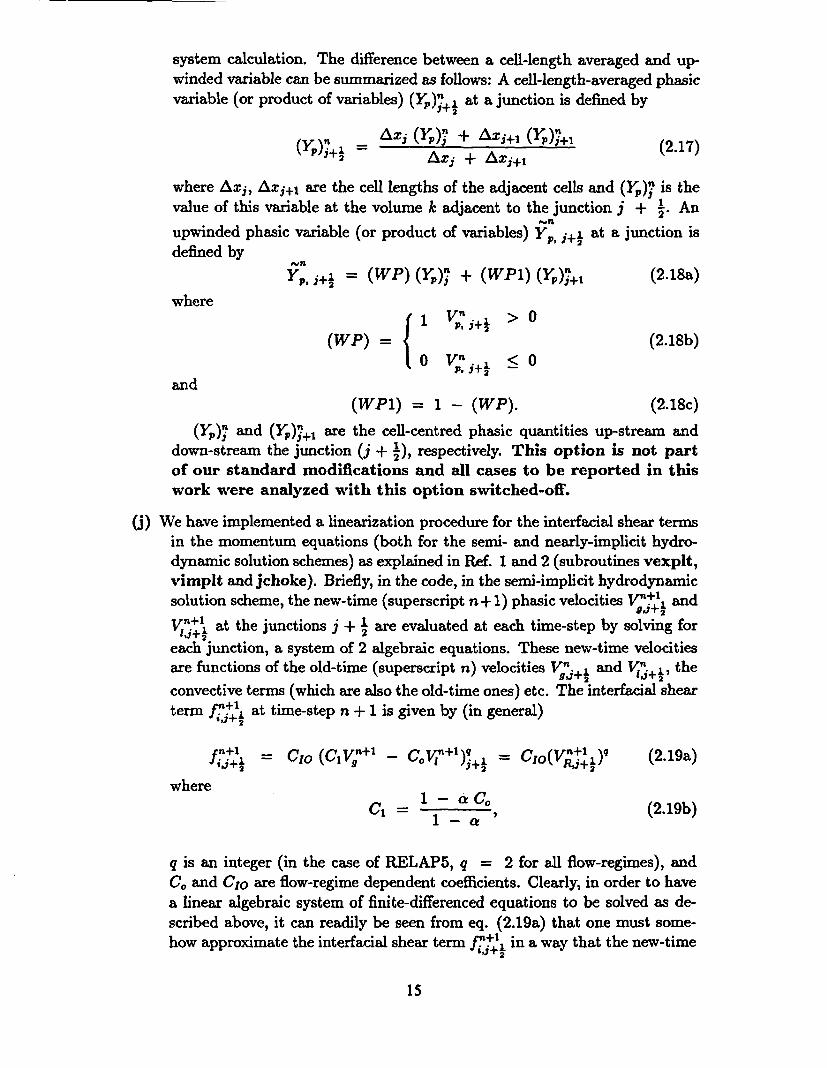
system calculation. The difference between a cell-length averaged and up-
winded variable can be summarized as follows: A cell-length-averaged phasic
variable (or product of variables) (Yp)>n+½ at a junction is defined by
= ax, (yr) 1 + Ax, ( (2.17)
Axi + AXj+1
where Axi, Axj+l are the cell lengths of the adjacent cells and (Y.)7 is the
value of this variable at the volume k adjacent to the junction j + 1. An
upwinded phasic variable (or product of variables) Y,, j+1 at a junction is
defined byýn
= (WP) (y•)l + (WPl) (YP)n+1 (2.18a)
where 1 T;,j++½ > 0
(WP) = V 0 (2.18b)
PP < 2and
(WP1) = 1 - (WP). (2.18c)
(Yp)•' and (P)+1 are the cell-centred phasic quantities up-stream and
down-stream the junction (j + 1), respectively. This option is not part
of our standard modifications and all cases to be reported in this
work were analyzed with this option switched-off.
(j) We have implemented a linearization procedure for the interfacial shear terms
in the momentum equations (both for the semi- and nearly-implicit hydro-
dynamic solution schemes) as explained in Ref. I and 2 (subroutines vexpIt,
vimplt and jchoke). Briefly, in the code, in the semi-implicit hydrodynamic
solution scheme, the new-time (superscript n+ 1) phasic velocities "+½ and•S/n2l
'+' at the junctions j + 1 are evaluated at each time-step by solving for
each junction, a system of 2 algebraic equations. These new-time velocities
are functions of the old-time (superscript n) velocities Vn+ and V"•+½ the
convective terms (which are also the old-time ones) etc. The interfacial shear
term f•,t+ at time-step n + 1 is given by (in general)2
=fi+ CIO (CV -Cl ,Vn",)1 C1 ,(V,+'i)' (2.19a)
where wC,- 1 - a C. (2.19b)
q is an integer (in the case of RELAP5, q = 2 for all flow-regimes), and
C. and CIO are flow-regime dependent coefficients. Clearly, in order to have
a linear algebraic system of finite-differenced equations to be solved as de-
scribed above, it can readily be seen from eq. (2.19a) that one must some-
how approximate the interfacial shear term f+t½ in a way that the new-timed J+ 2
15
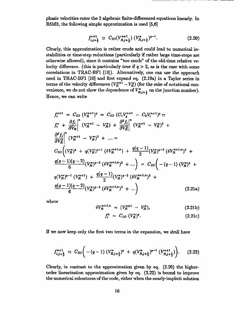
phasic velocities enter the 2 algebraic finite-differenced equations linearly. InR5M3, the following simple approximation is used [5,6]
i'+ -_ C1o(V +) (V;+½),9-. (2.20)
Clearly, this approximation is rather crude and could lead to numerical in-stabilities or time-step reductions (particularly if rather large time-steps areotherwise allowed), since it contains "too much" of the old-time relative ve-locity difference. (this is particularly true if q > 2, as is the case with somecorrelations in TRAC-BF1 [10]). Alternatively, one can use the approachused in TRAC-BF1 [101 and first expand eq. (2.19a) in a Taylor series interms of the velocity differences (V;+1 - VR) (for the sake of notational con-venience, we do not show the dependence of V;,+½ on the junction number).Hence, we can write
fil+, = CIO (V•Y+l) = C1 0 (Cv-+ - COY?1 )• -
Aq( + V)Vnl _OV;) -+ ;+1)2 +ir (V•+;+ _? -V; ) 3 + ..
CIOR((V + 2(V;+I'n) + q(q V)q- 2 (6V;+1 'n) 2 +
q(q - 1)(q - 2)(vN)9-3 (6V;+l1 ') 3 + =(q 1)(v;)q +6
q(v6)-) (+) + q(q- 1) M ( t
q(q- 1)(q- 2)(V;)q_3 (6V+,;l,) 3 + ) (2.21a)
where-6V;+l" = (V;+1 - Vn), (2.21b)
fn = CIO (V;)q. (2.21c)
If we now keep only the first two terms in the expansion, we shall have
CtIO(q( - 1) (V,+1½ 1 + q(V;,i)ql (V1~}.) (2.22)
Clearly, in contrast to the approximation given by eq. (2.20) the higher-order linearization approximation given by eq. (2.22) is bound to improvethe numerical robustness of the code, either when the nearly-implicit solution
16
scheme is used (which allows the code to take time-steps greater than theCourant limit), or when the semi-implicit method is used with relatively largeallowed time-steps: Much larger changes of the phasic velocities betweentwo successive time-steps can be tolerated without the danger of excitingnumerical instabilities [5]. Notice that if we want to keep even higher orderterms in the Taylor expansion given by eq. (2.21a), one introduces again non-linearities due to the (bV;+11P)2 terms. Here, there are two very interestingpoints on which the reader should be informed:
(a) In a recent unpublished work, we have actually shown that if the simplebubbly/slug interfacial shear correlation for pipes outlined under (k)below is used instead of the complex one already in the code, for sometransients, if the interfacial shear linearization shown in eq. (2.22) isused instead of the simple approach used in R5M3 (eq. (2.20)), onecan actually obtain completely different code predictions during somesystem calculations, particularly if eg the RSTs are very sensitive to theactual liquid fraction in the core (as is indeed the case for high-pressuretransients at axial elevations where the liquid fraction is very small).No significant differences were observed during the analysis of simple,separate-effect tests like the bottom-flooding tests we shall analyze inthe following section.
(b) The retention of higher-order non-linear terms in eq. (2.21a) can beachieved by a simple iteration procedure of the 2 finite-differenced al-gebraic phasic momentum equations in subroutine vexplt: Withoutgetting into any detail, the 2 algebraic equations are first solved for thenew-time phasic velocities with the linear interfacial shear in the formof eq. (2.22); subsequently, the expression
ffl.(k+l)' = cio (q(q - 1) (V•)-2 (bV;+l1,,(k+l))2 +
q(q - 1)(q - 2 ) (V)q-3 (bV;+l"n(k+l))3 +(2.23a)6 .. )
where6V;+l,'n(k+l) = (V- +l,(k+l) - V;,k) (2.23b)
(k is the iteration-index) is evaluated with the newly computed phasicvelocities and the 2 algebraic equations are solved again with the extraterm ff,(k+l)' added on the RHIS and with the new-time phasic velocitiesin the place of the old-time ones. The number of iterations is definedby the index k. We have shown that retaining higher-order terms in thelinearization of the interfacial shear terms in the way outlined above canalso significantly alter the code predictions as compared to the ones ob-tained when the linearization shown in eq (2.21) is used. The retention
17
of higher-order terms results in an even more numerically robust code
which runs without problems even for cases in which eg it was stopping
if the under-relaxation schemes were by-passed as explained under item
(h) above. Surprisingly enough, the simple iteration scheme mentioned
above only marginally increases the running time of the code; though,
for many cases, it has the effect of further reducing the mass-error of
the code. We have only implemented this iteration procedure in the
semi-implicit solution scheme.
In the analysis of transients on which we shall report in the following section,
we have only used in our modified code version the linearization as shown in
eq. (2.22).
The following 3 items are included in the code as options and are
not part of our standard modification package. A preliminary assess-
ment of these options has been performed with very encouraging conclusions
about their validity. Though, in this work, we shall only present selected
results obtained and conclusions drawn by activating these options whichwill clearly demonstrate some of their advantages when compared to the
ones already in the code. These options are assumed to be valid only if the
component is not a bundle.
(k) We implemented in the code the Ishii/Andersen's drift-flux based bubbly/slug
(new subroutine fldisbu) interfacial shear correlation as in TRAC-BF1 if the
component is not a bundle. We shall have
C PO ei a (1- a)s (2.24a)4o"
while the interfacial shear per unit volume will be
Pi -o ( a)5 (c 1 V - cOI1)4 , (2.24b)4a
whereCo = C. - (C. - 1) I U/7p, (2.24c)
Q,. = 1 + 0.2 (9.81 pi DH f• GI + 0.0001))"'° (2.24d)
and all the symbols have their usual meaning. For bundles, the modified
Bestion correlation is used as described before. Notice that in contrast to
the bubbly/slug interfacial shear package in the frozen version of the code(of which the EPRI correlation is a part) which depends on a large number
of local variables (which are bound to oscillate in the course of a transient
calculation) and conditions, the aforementioned correlation is a very simple
and straight-forward expression. Recently, we have shown that this very
complexity of the bubbly/slug interfacial shear package in RhM3 is mainly
responsible for the creation of an unacceptably high (more than the initial
18
liquid inventory of the system) mass-error in the analysis of a long (over10 hours real time) SB-LOCA transient. Furthermore, we showed that byremoving the original package and using the above correlation for pipes andthe modified Bestion correlation for bundles, the mass-error was reduced toonly a very small percentage of the initial liquid inventory of the system; formore details on this work, the interested reader is referred to Ref. 12 and13. Our whole set of modifications related to the mass-error reduction havealso been implemented in the RELAP5 part of the SCDAP code with whicha long SB-LOCA transient was also analyzed, with a very small mass-error;in contrast, the same large mass-error problem was encountered when thefrozen version of SCDAP was used [14]. Here, we should clearly state thatalthough our modification reduced the mass-error by more than an orderof magnitude, the problem is not really solved and the mass-error increasesagain if pressures lower than 3 bar are considered. We believe that a drasticmodification of the solution scheme in the code by introducing iterations isrequired before the excessive mass-error problem is properly addressed andsolved.
(1) As an option, we have implemented the drift-flux based annular flow interfacialshear correlation of TRAC-BF1 [10]. (subroutine fidisan). One defines
C 1 + (1- a) (1 - ) (2.25a)(a + a)
where
a I1 + 75 (1 - a) */ (2.25b)
e is the fraction of the entrained liquid and is calculated as in TRAC-BF1in the following way:
e = max( (xe - 0.03),0.0)/ 1 + (0.1 + xe) 2 (2.25c)
where
xe 105 ( ri 1 D 5 Rei) . (2.25d)
Rel - IGiI DH / Py, (2.25e)
G = (1 - a)p, Vj, (2.25f)
D* = D. r9.81 (P, - p,) / 0, (2.25g)
- IJ,! /V/ov 9.81 (p! - p,) (p, / (p1 - p,)).6- 6 / pg, (2.25h)
and= a V . (2.25i)
Then, we shall have
C = 0.015 pi a (a + a) 2 (2.26a)DH
19
and the interfacial shear per unit volume will be
0.015 p' a (a + a) 2 (C,• - C0 Vi) 2. (2.26b)DH
Notice that the aforementioned annular flow interfacial shear correlation as-sumes that the continuous phase is the liquid and hence, the liquid densitypi appears as multiplier. This makes it up to two orders of magnitude higherthan the ones of Wallis which is in the code and is based on the assumptionthat the continuous phase is the vapour [9]. Finally, the following values ofCio are used in the phasic momentum equations:
Ifl - a < 0.1,CIO = 10 CIO (1 - a). (2.27a)
If1 - e < 0.1,CIO = 10 CIO. (2.27b)
Ifl - e > 0.1, C'0c1o = 1 -ce (2.27c)
This formulation is identical to the one in TRAC-BF1 and all the symbolsare self-explanatory. Notice that also this formulation avoids a strong de-pendence on local variables (with the exception of the distribution coefficientCQ (and hence, also C1) which, in any case, is bounded both from below by1 and from above) and that the interfacial shear coefficient CIO is mainly afunction of the void fraction. Though, the corresponding model in R5M3 isalso relatively simple. Here, we should mention that the employment of theaforementioned two options (if the component is not a bundle) has resultedin large reductions of the code mass-error (sometimes by more than an or-der of magnitude) for long SB-LOCA transients, most probably due to thesimple mathematical form of these correlations and their lack of dependenceon a number of local variables [12,13].
(m) The Ishii dispersed flow interfacial shear correlation (as in TRAC-BF1) wasimplemented as an option (subroutine fldishi). For this flow regime, CIo isdefined by
C = a(1 - a)(pl -Pq)g (2.28)
and the interfacial shear per unit volume is
S= a4(1 - a)1(p - Pg)g(CV _ Co1) 4 ; (C. = C1 = 1) (2.29)
where g is the gravity constant and V,. is the equilibrium relative velocity ofthe droplets calculated in the following way: First, one defines the dropletradius rdish calculated from Ishii's equation
20
rd~.,h 0.006 (a (pi'" p2 " (2.30)
Pg (a Vg) 'Pg1 RP ).3
where V. is the steam velocity and Reg the steam Reynold's number. Nextthe Ishii's critical drop size is given by
rcrt=2( 2o os NO (p 0.33=7 d,c = 2 g (pi - pg) () (P . ))0.)0.5 " (2.31)
We now define two equilibrium relative velocities V, for the droplets, onein the "wake" region and one for the "distorted" drops, V,(,) and V1 (d)
respectively
Vr(W) = 0.5 rd a (((p, - pg) g)2)03 (2.32a)
P9 P9
and
V,(d) = vF a.15 (" g (P1 - pg))o.25 (2.32b)pg2
where
= max (min (rdih,, 2 g (p, - p)), 0.0001). (2.32c)
Finally, if rd,.ih > rd, V,(d) is used as the relative velocity of the dropletsin eq. (2.28) otherwise, V,(,) is used. In eq. (2.19a), q = 4. Preliminaryassessment of this option resulted in over-estimation of the liquid carry-over during low flooding rate bottom flooding experiments: Clearly, theaforementioned correlation over-estimates the interfacial shear. This in itselfagrees with the statements we made at the end of item (b) above, ie, for anumber of reasons, one has to assume in bundles a lower interfacial shearthan in tubes in order to avoid excessive liquid carry-over. Effectively, bydoing this, we are somehow compensating for effects like wetting of spacers(and hence, decrease of the liquid carry-over) or geometry-effects which arenot accounted for in the codes.
(n) Similarly to our work on the version 7j of the code, a number of additionaloptions have been implemented in R5M3.1 like the first upwind scheme inthe convective terms of the momentum equations and the inclusion of thespatial derivatives in the virtual mass term which read [5]
F = - k,, ckgkp O Oz O z) (2.33)
(where p = ag pg + a, pg) for the steam momentum equation (and similarlyfor the liquid, with the subscripts g and I interchanged). With the version 7jof the code, we have tried to assess a number of these options and comparethe code predictions with the option(s) switched on and off. Though, weshall not comment on these side efforts in this work.
21
3 ASSESSMENT OF THE MODIFIED CODEAND COMPARISON WITH THE FROZEN
VERSION
We shall now assess the modified code by comparing its predictions with measure-
ments from a number of separate-effect and integral test experiments, as well as
with the predictions of the frozen version. For all the case analyzed, the top QF
option was not activated; though, activation of this option has shown that the
model indeed works properly and predicts (for some cases) a gradual quenching of
the nodes from the top due to a downwards propagating QF.
We shall present and discuss the following cases: A constant inlet liquid
velocity bottom flooding experiments in the heater rod bundle NEPTUN at PSI,
as well as a similar FLECHT-SEASET test, the Oak Ridge THTF low power film
boiling experiment Nr. 3.08.6C, the LOFT LP-LB-1 experiment, a hypothetical
200% LB-LOCA calculation in a two loop 1130 MWth commercial PWR and
the LOBI SB-LOCA BL34 experiment. Finally, we shall demonstrate that in
principle, our top QF logic is functioning and we shall show how it affects the
RSTs in the upper regions of NEPTUN and the LOFT when compared to thecorresponding cases in which the top QF logic is not activated. A number of
boil-off tests in NEPTUN [15] were also analyzed [1,16] but we shall not show or
discuss the results here other than saying that although the frozen version of the
code over-predicted the amount of water expelled and hence, predicted an earlier
dry-out of all axial rod positions, our modified code with the modified Bestion
correlation [7] re-activated resulted in excellent agreement between measurements
and predictions, a result which is not surprising.
3.1 The NEPTUN and FLECHT-SEASET bottom flood-
ing tests
We shall start by briefly discussing the set of NEPTUN [15] and FLECHT-SEASETbottom flooding experiments. The nodalizations used in both of these tests are the
same with the ones reported in Ref. 8. Whenever possible, the code predictions
will be compared to the measurements.
The initial conditions of the bottom flooding NEPTUN experiment on which
we shall report are [1,4]
Nr. 5036 (P = 4.1 bar, AT, = 10 K, VIN = 0.015 m/s),
while the initial conditions of the FLECHT Test Nr. 31701 are
FLECHT Test Nr. 31701 (P = 2.7 bar, AT. = 79 K, VIN = 0.15
22
m/s)
In Fig. 1, we show the measured and predicted RSTs and predicted totalHTCs at axial elevations of 0.714 m and 0.946 in both by the frozen [1,2,4] andmodified versions of the code for the NEPTUN bottom flooding experiment (themeasured HTCs axe not shown in the figures; they axe very close to the onespredicted by the modified code). Clearly, the unphysical modeling of the HTCin the code and, primarily, the low mass-flux CHF behaviour of the Groeneveldlook-up tables as explained under (f) in the previous section, result in a highlyoscillatory total HTC and hence, to unphysical code predictions for the RSTs:This "pseudo-enhancement" of the HTC leads to the unphysical fast decrease ofthe RSTs which decrease to saturation in an almost continuous fashion (Fig. 1A); in contrast, at the higher axial elevation (Fig. 1 B), after the initial decrease,the RST stays constant. Not surprisingly, other variables like void fraction andsteam velocities also exhibited a highly oscillatory behaviour when calculated bythe frozen version [1,4]. On the other hand, the modified code predicts the RSThistories well and the predicted HTC are very smooth. indeed. This is also thecase for other variables like void fraction and steam velocities. In particular, asone can see in Fig.2, both the void fractions at different axial elevations and thecollapsed liquid level in the core computed by the modified version were very closeto the experimental measurements. The elimination of the unphysical oscillationsis primarily the result modifying the low-mass flux behaviour of the qcHF obtainedby the Groeneveld tables and not of the new heat transfer package used duringreflooding; the merits of the new heat transfer package is that it actually takes intoaccount (empirically) the experimentally observed dependence of the heat transferas a function of the distance from the QF; this is bound to result in simulations inwhich the predicted RSTs exhibit the right trends, particularly in the vicinity ofthe QF. Although not shown in this work, a number of other (five of them) bottomflooding experiments in the NEPTUN facility were analyzed with both versionsof the code and while the frozen version was always resulting in unphysical anderroneous predictions [1-4], the modified code predicted the measured variables(RSTs, Collapsed Liquid Levels etc) very well indeed.
In Fig. 3, we show the measured and predicted RST histories at axial eleva-tions of 2.01 m and 2.56 in for the FLECHT-SEASET test. Also here, one can seethat the predictions obtained by the modified version axe closer to the measure-ments and are more physically sound; generally, the inclusion in the code of anempirical wall-to-liquid heat transfer correlation similar to the one in CATHAREHTC with its explicit dependence on the distance from the QF is primarily respon-sible for this good agreement between measurements and predictions obtained bythe modified code. Two more FLECHT-SEASET bottom flooding experimentswere also analyzed with both versions and there was always good agreement be-tween measurements and predictions of the modified code; in contrast, the pre-dictions obtained by the frozen version were always plagued by the problems wediscussed in the previous section. Hence, we can safely say that as far as re-flooding is concerned, the improvements brought about by our new wall-to-liquid
23
heat-transfer package as well as by the other modifications which are of importance
during this process seem to be of general validity.
3.2 The THTF 3.08.6C test
The Oak Ridge THTF test Nr. 3.08.6C is a low-power film-boiling experiment
with an imposed inlet mass flow. From t = 0 s to t = 50 s the bundle power
is 2.4 MW while from 50 s to 80 s, the time-power (in MW) pairs are (51.7,8.1),
(52.4, 8.0), (71.0,8.0), (74.8,3.2) and (80.0, 3.1). The imposed liquid mass flowat the inlet was 7.0 kg/s from t = 0 s to t = 50. s, and gradually decreased
to 0.77 kg/s at t = 80 s. The inlet pressure and liquid temperatures were at
t = 0 s 128 bar and 537.5 K, respectively, while at t = 80 s were 63.7 bar and
541 K. The facility was modelled by 45 volumes of length varying from 0.104 m
to 0.04 m [17].
The case was analyzed both with the frozen [17] and our modified version ofthe code, and by using both the semi- and nearly-implicit hydrodynamic solution
schemes. No reflooding heat transfer package is activated in these runs; hence,
one can partly utilize this case for assessing the new wall-to-liquid heat transfer
package used when there is no reflooding. Furthermore, we shall show that ourmodifications (and, most probably, the higher-order linearization scheme of theinterfacial shear term in the phasic momentum equations) have a "smoothing"
effect on the predictions obtained by using the Courant-violating nearly-implicit
numerics.
In Fig. 4A and 4B, we show the measured RST histories at two different axial
elevations and compare them to the ones predicted by the frozen and modifiedversions of the code, when the standard semi-implicit scheme is used. At level
F, both versions predict an earlier CHF [17] and under-estimate the RSTs later
in the transient; though, the RSTs predicted by the modified code are for almost
the whole time "parallel" to the measured ones, while the frozen version, under-
estimates the HTC after approximately 60 s. At the higher axial elevation (Fig.
4B), both versions predict very similar RSTs. The situation is basically much
different when the nearly-implicit solution scheme is used: One can see from Fig.
4C and 4D that although the RSTs predicted by the modified version of the code
are less close to the measured ones than the ones obtained when the semi-implicit
scheme was used, the ones obtained by using the frozen version of the code areexhibiting a totally unphysical behaviour, indicating that some auxiliary variables
are oscillating and are inducing RST oscillations.
Generally, we can say that the modified code predicts the RSTs of this testa little better than the frozen version and hence, our new heat transfer package
used when the reflooding is not activated seems to perform well; though, when the
nearly-implicit scheme is used, the predictions of the modified code are certainly
much better and more physically sound. The reason that there are relatively large
24
differences between the predictions obtained when the two different hydro-dynamicsolution schemes are used is a subject on its own and we shall not elaborate onit in this work. Concluding this sub-section, we should say that we have alsoanalyzed the THTF test 3.03.6AR with both versions of the code: In contrast tothe measurements which show at different axial positions a dry-out, a subsequentRST increase and a subsequent decrease of the RSTs at a very slow rate (up tothe time of 20 s, the RSTs are between 750 K and 850 K), the frozen version ofthe code predicts that the temperatures start decreasing fastly at approximately10 s, probably due to the Chen transition/film boiling correlation. In contrast,the RSTs predicted by the modified code follow the experimental RSTs (for mostaxial elevations) very closely.
3.3 The LOFT LP-LB-1 test
We shall continue in this and the following sub-sections our comparison of thepredictions obtained by the two versions of the code by considering integral testexperiments as well as a hypothetical LB-LOCA in a two-loop commercial PWR.Firstly, in Fig. 5, we present 2 sets of measured and predicted RSTs for the LOFTLP-LB-1 test at axial elevations of 27 and 31 inches; the test was analyzed usingthe input deck of Ref. 18. Here, apart from the analysis performed with the frozenversion of the code, we analyzed it with our modified version but also with theversion in which the options described under (k) and (1) above were activated ifthe component was not a bundle. From these figures, the following conclusionscan readily be drawn:
(a) The frozen version of the code is not capable of capturing the trends of themeasured RSTs even qualitatively.
(b) The modified code predicts the measured RSTs better than the frozen ver-sion; though, even the modified version under-predicts the peak RSTs, byapproximately 200 K. Clearly, this is most probably due to the fact thatthe amount of liquid in the core at the beginning of the reflooding phase isover-predicted.
(c) When the options (k) and (1) of the previous section are switched-on, the pre-dicted RSTs are now higher than before and hence, closer to the measuredones. In fact, the differences between measured and predicted peak RSTsare now in the range of 50 K. We have actually verified that this differencecan be almost exclusively attributed to using a different annular flow inter-facial shear in the pipes (item (1)). This is an indication that the differencesbetween the measured and predicted RSTs by our modified version are mostprobably due to hydraulic (liquid-distribution) rather than heat-transfer rea-sons. Additionally, these differences demonstrate in a very clear fashion thesensitivity of the code predictions during system calculations to the selection
25
of a particular interfacial shear correlation in one flow regime even in regions
other than the core.
3.4 A hypothetical LB-LOCA in a two-loop 1130 MWthcommercial PWR
As a next test of the way that our model changes affect the predicting capabili-
ties of the code during the analysis of a LB-LOCAs, we analyzed a two-loop 1130
MWth commercial PWR hypothetical 200 % LB-LOCA transient with the input
deck also supplied to us by Liibbesmeyer [19]. Since our main aim here is to
present and discuss the differences in predicted RST histories between the frozen
and our modified version of the code, we shall avoid any discussion in relation to
plant modeling and nodalization other than saying that the core was divided into
a low, medium and high power regions while in the latter, a hot rod was assumed.
In Fig. 6, we compare the RST predictions of the modified and frozen versions for
the hot rod in the high power region at the peak-power axial elevation. One can
clearly see that the predictions of the frozen version exhibit a sharp RST decrease
at approximately 7.5s after the break opens, due to the problematic Chen transi-
tion/film boiling correlation which attains a very high value at IGI = 271 kg/m 2 /s
and when later IGI decreases, the RSTs start increasing again. A consequence of
this is that the peak RSTs predicted by the frozen version of the code are much
lower than the ones predicted by the modified version since with the former, a
large amount of stored energy is removed during the first 12s of the transient, due
to the high value attained by the Chen transition/film boiling wall-to-liquid heat
transfer correlation. Sensitivity studies have also shown the dependence of the
peak clad temperature at certain elevations on the assumed value of TMIN which
is used on the heat transfer package activated when there is no reflooding (see
item (e) in section 2).
3.5 The LOBI SB-LOCA BL34 test
Concluding this section, we shall present some results from the analysis of the
LOBI SB-LOCA BL34 experiment [20] for which the reflooding option is not acti-
vated. By doing this, we shall try to assess the way (if any) that our modifications
(and in particular, the new heat transfer package used when the reflooding is not
activated) affects the code predictions for a SB-LOCA calculation. Though, we
must stress once more that a much wider assessment of the modified code with a
number of SB-LOCA tests is needed before we can say that we are confident that
our version of the code performs better than the frozen version also for SB-LOCA
transients; this is a necessary procedure for further qualifying our modifications.
In Fig. 7, we show the measured and predicted RST histories at two axial
elevations, as well as the collapsed level in the core. Notice that neither the
26
modified code nor the frozen version predict the first dry-out observed in themeasurements. Both at level 5 and level 8, the modified code predicts the RSTssignificantly better than the frozen version: In particular, at level 5, the dry-outtime is predicted better by the modified code but the peak RST is under-estimated.At level 8, the modified code predicts an earlier dry-out but the RST history iscloser to the measurements than the one predicted by the frozen version. Finally,the collapsed core level is predicted much better by the modified code, althoughboth versions are over-predicting the initial level collapse. Hence, also for thiscase, our modified code performs better than the frozen version and our new wall-to-liquid heat transfer package used when the reflooding is not active seems towork well and without any problems.
Finally, in Fig. 8, we demonstrate the ability of the modified code to modeltop quenching should this option is activated. In particular, in (A) and (B), weshow the predicted RSTs for the 2 top nodes at elevations of 1.41 m and 1.642m, respectively, for the NEPTUN experiment Nr. 5050 by the version in whichthe the top quench model is activated and compare them to the case for which itis not. Similar plots are shown in (C) for the axial elevation of 49 inches in theLOFT for the LP-LB-1 test. For the NEPTUN case, the measurements actuallyshow that the nodes in (A) and (B) are quenching at approximately 43 s and 21s, respectively. Hence, our top QF model which, as we already mentioned before,cannot predict the time that the top QF is initiated, predicts an earlier quenchingof these two elevations. Finally, for the LOFT test, the earlier quenching of thiselevation when the model is activated is also evident. The measurements actuallyshow a quenching at approximately 16 s followed by a new heat-up at 20 s, anew RST drop at 40 s and a final quenching at approximately 52 s. Clearly, ourmodel (or any other model) cannot reproduce this behaviour. Hence, both for theNEPTUN separate-effect test and for the LOFT integral test, the activation ofthe top quench option in the code results in predicting a downwards propagatingQF. We should make clear here once more that we are assessing the capabilityof the modified code to generally predict the top quenching rather than claimingthat we can achieve quantitative agreement with measurements: For this, as wehave already mentioned before, one has to adjust the coefficients of the model byutilizing a large number of experiments.
4 CONCLUDING DISCUSSIONS
In this work, we have outlined a number of modifications, model changes andoptions introduced in R5M3.1 which result in better and more physically soundcode predictions. These modifications include items like modeling of the wall-to-liquid heat transfer, interfacial shear, transition criteria from the pre- to the post-dry out interfacial closure laws (and vice versa), modification of the low mass-fluxlimit of the CHF predicted by the Groeneveld look-up table, partial removal ofthe under-relaxation schemes of the interfacial closure coefficients etc. Clearly,
27
most of these modifications are generic, since they are altering some of the basic
physical models in the code. Additionally, a number of options were introduced
in the code, like the possibility of using the same interfacial shear correlations as
in TRAC-BF1. Without any doubt, there is a number of other areas on which
attention must be paid and a careful assessment and validation of other models
along the lines summarized in the Introduction should be pursued; this, as we
have already mentioned, is not only restricted to the actual physical correlations,
but also to "numerics-related" items like under-relaxation schemes, flow-regime
transition smoothing etc. which as far as code predictions are concerned, they
may overwhelm the physical models.
In relation to our particular fields of interest and as far as physical model-
ing is concerned, the main code deficiencies we identified were in the modeling
of the wall-to-liquid heat transfer coefficient in the post-CHF wall heat transfer
regime (this being the case independently of whether one is modeling reflooding
or not), the adverse effects of the oscillatory behaviour of the CHF predicted from
the Groeneveld look-up table (mainly for low mass-fluxes), the unphysically small
dispersed flow interfacial shear at lower pressures arising from the assumed unphys-ically large minimum average droplet diameter and the false condition imposed on
the interfacial shear coefficient (both of which greatly affect the code predictions
during reflooding), the effect of the under-relaxation schemes of the interfacial clo-
sure coefficients (particularly in the presence of "numerical" oscillations), as wellas a number of other minor points which, nevertheless, can show-up and become
important under certain conditions.
A number of separate-effect and integral test experiments were analyzed with
the modified version of the code, and the predictions were compared with the
ones obtained by the frozen version and (when possible) with the measurements.
Through the course of our work, we closely monitored not only the "observable"variables like RSTs or liquid levels, but also the "non-observable" ones like liquid
velocities, steam velocities etc, and looked carefully at possible unphysical large-
amplitude oscillations in these quantities; this could indicate a possible modeling
deficiency and is bound to affect the predictions of the variables of interest (eg
RSTs).
Without any exception, the predictions of the modified code were much closer
to the measurements, in most cases free of unphysical oscillations, and always
more physically and conceptually sound than the ones of the frozen version. We
attribute these improvements to the more realistic and physically sound modeling
of a number of processes and constitutive relations in the modified version of the
code. The tests analyzed by both code versions included bottom reflooding in a
heater rod bundle at PSI and in the FLECHT-SEASET bundle, the Oak Ridge
THTF low power film boiling experiment Nr. 3.08.6C, the LOFT LB-LOCA LP-
LB-1, a hypothetical 200% LB-LOCA in a two-loop 1130 MWth commercial PWRand the LOBI BL34 SB-LOCA test. Furthermore, we demonstrated that our newly
implemented "top QF model" performs as expected, although we have actually no
28
way of initializing it and for this, we can only rely on the internal logic of the code.Clearly, although we feel confident that at least as far as reflooding is concerned,our modifications really capture the physics of the process and as such we canconsider them as being of quite general validity, a much wider assessment witha large number of different transients is required before one can make generaland definite statements about the capability of our modified code to correctlycapture (and predict) the phenomena in system calculations not only during LB-LOCA's (an ability which we have already clearly demonstrated and on which wehave spent considerable effort), but also during other transients. In particular, itwould be of interest if cases analyzed with the frozen version of the code for whichunphysical predictions have been obtained and reported, could be re-analyzed withour modified version. Though, since our physical model changes are mainly relatedto wall heat-transfer and interfacial shear (out of which the former is predominantlyaffecting the core response), we do not think that will have any pronounced effectin the analysis on Chapter 15 transients (malfunction of components etc).
An area which we also discussed in this work (though admittedly not toa great extent) is the effect of the very complex bubbly/slug interfacial shearpackage of the frozen version of the code on the unacceptably high large mass-errorobserved in the analysis of long SB-LOCA transients: We have shown that thecomplexity of this package is mainly responsible for this and the implementationin the code of the simple Ishii/Andersen model of TRAC-BF1 (if the componentis not a bundle; in the bundle, the modified Bestion correlation is used) solvesthis problem not only in RSM3 but also in SCDAP. Clearly, the important lessonfrom this is that one should as much as possible avoid introducing very complexmodels and correlations in these codes, even if outside the code environment, theyare proved to be superior to other, simpler models: In the complex environmentof the code, the complexity of a model may excite local oscillations which caneventually adversely affect the final code predictions. Finally, we touched uponthe influence of the degree of linearization of the interfacial shear term on thecode predictions; although we did not actually show any concrete examples, westated that our recent investigations have shown that under certain conditions,this effect can be quite profound. Saying this, we should stress once more that adrastic modification of the solution scheme in the code by introducing iterations isrequired before the excessive mass-error problem is properly addressed and solved.
Concluding, we should repeat that as we stated in the Introduction, we arenot claiming that all problems associated with R5M3 are solved or that there areno other areas than the ones addressed in this work that attention is required.We believe that the process of improving the codes in general and in particular,R5M3, may actually have "never-ending tendencies", since there will always betransients which will exhibit some "unforseen peculiarity" which, somehow, wouldbe desirable to "include" in the code in the form of a special model. In this respect,the effort to improve the predicting capabilities of the code is limited to doing one'sbest to correctly model the well-understood physical processes in a consistent andclear fashion, and in trying to avoid "numerics-related" problems like excitement
29
of unwanted oscillations or large mass-errors which may not only adversely affect
the code predictions, but may also result in termination of a particular run dueto bad convergence of the numerical solution or to water property error. Clearly,
the former goal can be more easily achieved than the latter, since in a complicated
entity like a transient thermal-hydraulics code, there may be a large number of
competing effects which may excite unwanted oscillations. Independently of the
various difficulties which may be encountered in the process of improving R5M3, we
hope that we have clearly demonstrated in this work that with some systematic and
co-ordinated effort and by following the procedure outlined in the Introduction,
R5M3 can indeed be greatly improved (not only from the point of view of physicalmodeling) and confidently used also for LB-LOCAs. We certainly hope that in the
future we shall be able to test (and hopefully, further qualify) our modified version
of R5M3.1 with transients which were not successfully calculated with the frozen
version of the code and assess the extent to which our modifications are improving
its general predicting capability. Clearly, this is the only sensible way to realizethe goal of gradually and systematically improving R5M3.1 in accordance with the
philosophy outlined in the Introduction.
Acknowledgements
We would like to thank Dirk Liibbesmeyer for making available to us his LOFTLP-LB-1 and commercial PWR input decks, and for communicating to us and
discussing the large mass-error problem in his SB-LOCA calculation with R5M3.
A number of interesting discussions on the mass-error problem of SCDAP with
Jonathan Birtchley are greatly acknowledged. We are grateful to the University of
Pisa, Italy, and in particular, to F. D'Auria for making available to us the LOBIinput deck used in this work. Finally, we are grateful to V. Faluomi and S. N.
Aksan for providing us with their THTF input deck.
References
[1] G. TH. ANALYTIS, A summary of model changes and options in RE-
LAP5/MOD3. Paper presented at the 2nd CAMP Meeting, May 10 - 13,
1993, Brussels, Belgium.
[2] G. TH. ANALYTIS, Development and assessment of a modified version of
RELAP5/MOD3: A search for excellence, Invited paper presented at the
RELAP5 International User's Seminar, Baltimore, Maryland, USA, August
29 - September 1, 1994
[3] G.TH. ANALYTIS, The effect of CHF modeling on some numerical oscilla-tions of RELAP5/MOD3 during reflooding, paper presented at the Interna-
30
tional Working Group Meeting on CHF Fundamentals, March 3 - 4, 1993,University of Braunschweig, Germany.
[4] M. SENCAR and S.N.AKSAN, Evaluation and Assessment of RefloodingModels in RELAP5/MOD2.5 and RELAP5/MOD3 Codes using Lehigh Uni-versity and PSI-NEPTUN Bundle Experimental Data, NURETH-7 Confer-ence, NUREG/CP-0142, Vol. 3, pp 2280 - 2289 (1995).
[5] K.E. CARLSON et al., RELAP5/MOD3 Code Manual Volume IV: Modelsand correlations (Draft), June 1990.
[6] V.H. RANSOM et.al., RELAP5/MOD2 Code Manual Volume 1: Code Struc-ture, System Models and Solution Methods, NUREG/CR- 4312, (1985).
[71 G.TH. ANALYTIS and M. RICHNER, Trans. Amer. NucL Soc., 53, 540(1986).
[8] M. RICHNER, G. TH. ANALYTIS and S. N. AKSAN, Assessment ofRELAP5/MOD2/36 Cycle 36.02, using NEPTUN Reflooding ExperimentalData. NUREG/IA-0054, 1992.
[9] G. TH. ANALYTIS, Developmental Assessment of TRAC-BF1 with Separate-Effect and Integral Reflooding Experiments. NURETH-5 Conference, 21-24/9/1992, Salt-Lake City, Utah, U.S.A, Vol. I, pp 287 - 293.
[10] D.D. TAYLOR et al., TRAC-BD1: An Advanced Best-Estimate ComputerProgram for Boiling Water Reactor Transient Analysis, NUREG/CR-3633(1984).
[11] G. TH. ANALYTIS and P. CODDINGTON, The effect of donor cell differ-encing of some terms of the momentum equations of TRAC-BF1 on code pre-dictions, NURETH-5 Conference, 21-24/9/1992, Salt-Lake City, Utah, U.S.A,Vol. II, pp 287 - 293.
[12] G. TH. ANALYTIS, A note on the effect of the wet-wall interfacial shearcorrelations on the mass-error of RELAP5/MOD3.1: A SB-LOCA transientcalculation, PSI Internal report, TM-42-94-15 (1994).
[131 G. TH. ANALYTIS, The effect of the wet-wall interfacial shear correlationson the mass-error of RELAP5/MOD3.1, Trans. Amer. Nucl. Soc., 73, 513(1995).
[14] This was communicated to us by J. BIRTCHLEY who was running a SB-LOCA with SCDAP (1994).
[15] H. GRUTER, F. STIERLI, S.N. AKSAN and G. VARADI, NEPTUN Bundlereflooding experiments: Test Facility description, EIR Report Nr.386 (1980).
[16] F.D'AURIA, V. FALUOMI and S.N.AKSAN, "New Trends in Nuclear SystemThermohydraulics", Proceedings, Vol.1, "Primary and Secondary Thermohy-draulics", pp 479 - 489, Pisa, Italy, May 30th - JUne 2nd, 1994.
31
[171 V. FALUOMI, F. D'AURIA, M. LEONARDI and S. N. AKSAN, Extrapola-
tion of experimental and calculated CHF data, DMCN-NT 218, Pisa Univer-
rity, Italy, October 1993.
[18] D. LUBBESMEYER, Post-Test-Analysis and Nodalization Studies of OECD
LOFT Experiment LP-LB-1 with RELAP5/MOD2/CY36.02, PSI Report
Nr.91 (1991).
[19] The input deck of this commercial PWR plant was put together and supplied
to us by D. LOBBESMEYER (1994).
[20] F. D'AURIA and G.M. GALASSI, Assessment of RELAP5/MOD2 code on
the Basis of Experiments performed in LOBI Facility, Nuclear Technology,
Vol 90, Nr. 3 (1990)
32
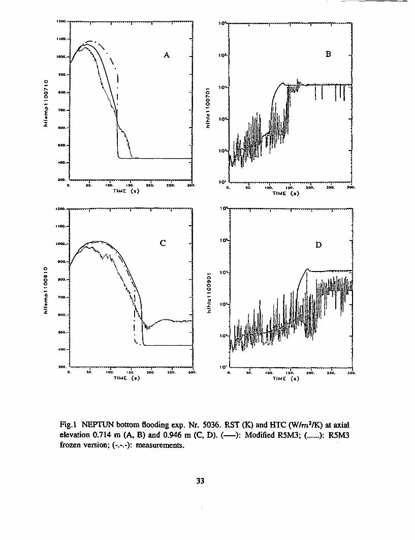
0 oI~ ......0 8oo.- 00
700.-
10• ..-
400.-
TIME (s) TIM 50(0s)5. 0. 25.TIME s)TIME: Cs)
11000.
,OM.- C 10* D
too.-
010-
0 600-0
0 70.-i 101 ' '" •I R • i "
N.N500.
•! .- . - I .-
0. 50. 10.. 15O. 200. 250. "0. 0. S0. t1[ o , I 200 250. 3C
TIME (s) TIME (s)
Fig.I NEPTUN bottom flooding exp. Nr. 5036. RST (K) and HTC (WM 2 IK) at axialelevation 0.714 m (A, B) and 0.946 m (C, D). (-): Modified R5M3; ( ....): R5M,3frozen version; (---:measurements.
33
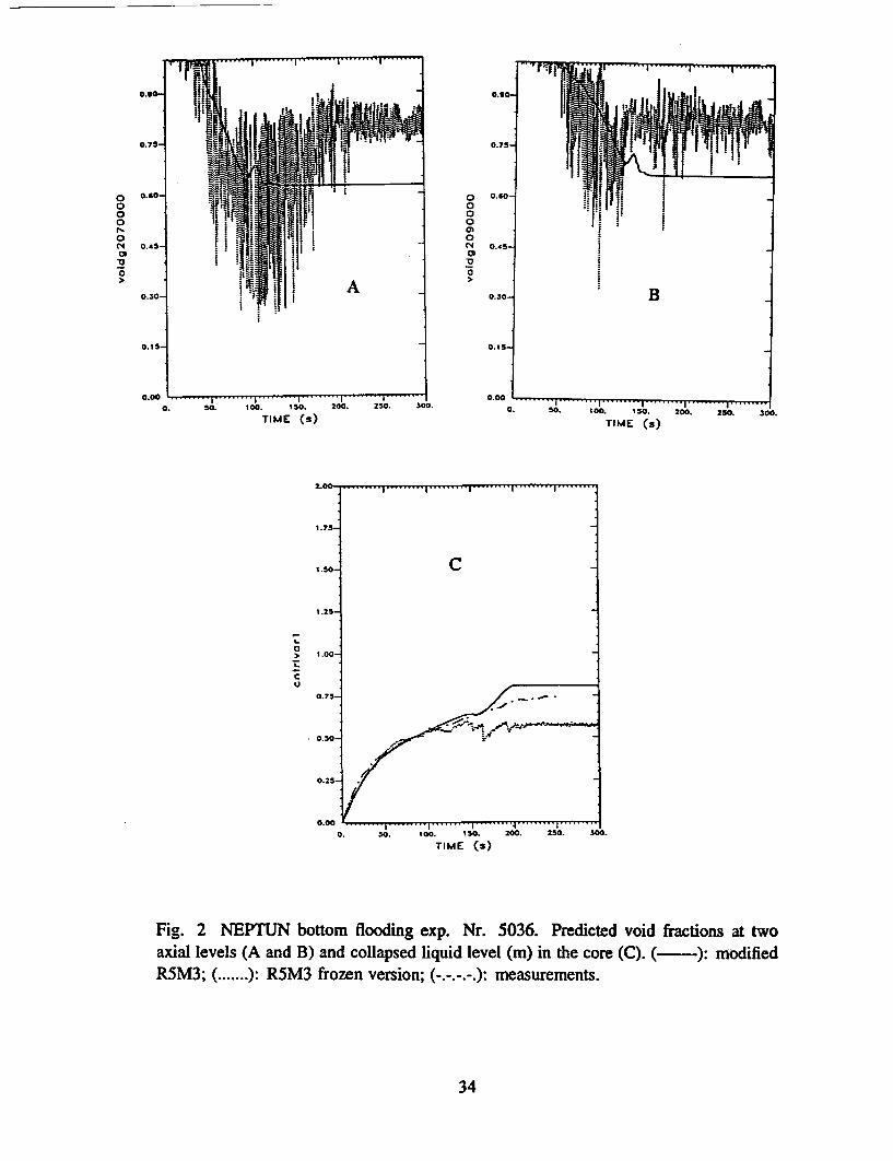
I " I ...... ..... -.- -- ...
0000N0N0
'0
0.75-
0.60-
0.45-
0.30-
0.15-
0.00
!ii
I
mm-:
I I
III-
I I
iiii
00000(C40N30,Il
Il
A
.... ... .... ... .. . ....... .... .. .. .....-. I I . I
0. 50. 100. 10.
TIME (s)200. 250. 300.
TIME (s)
a
CI,
2.00- .--- ---------
1.75-
1.50- C
1.25-
1.00-
0.75-
0.2S- '
0."' . . . . . . . I "4 I
50. 100. $SO. 200. 250.
TIME (s)3w0.
Fig. 2 NEPTUN bottom flooding exp. Nr. 5036. Predicted void fractions at twoaxial levels (A and B) and collapsed liquid level (m) in the core (C). (-): modifiedR5M3; ( ....... ): R5M3 frozen version; (-.-.-.-.): measurements.
34
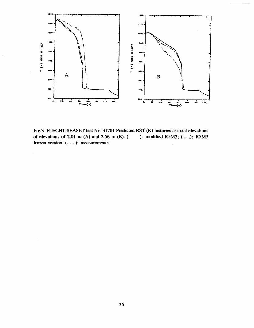
SOO-
0 0
0
30 0
4). to. -0. 40. W1. 100. 120. 1"4. 0. 20. 4,0. 00. M•. AGO. 120, d.Timro(s) Time(s)
Fig.3 FLECHT-SEASET test Nr. 31701 Predicted RST (K) histories at axial elevationsof elevations of 2.01 m (A) and 2.56 m (B3). ( ):modified R5M3; ( ...... ): R5M3frozen version; (.-):measurements.
35
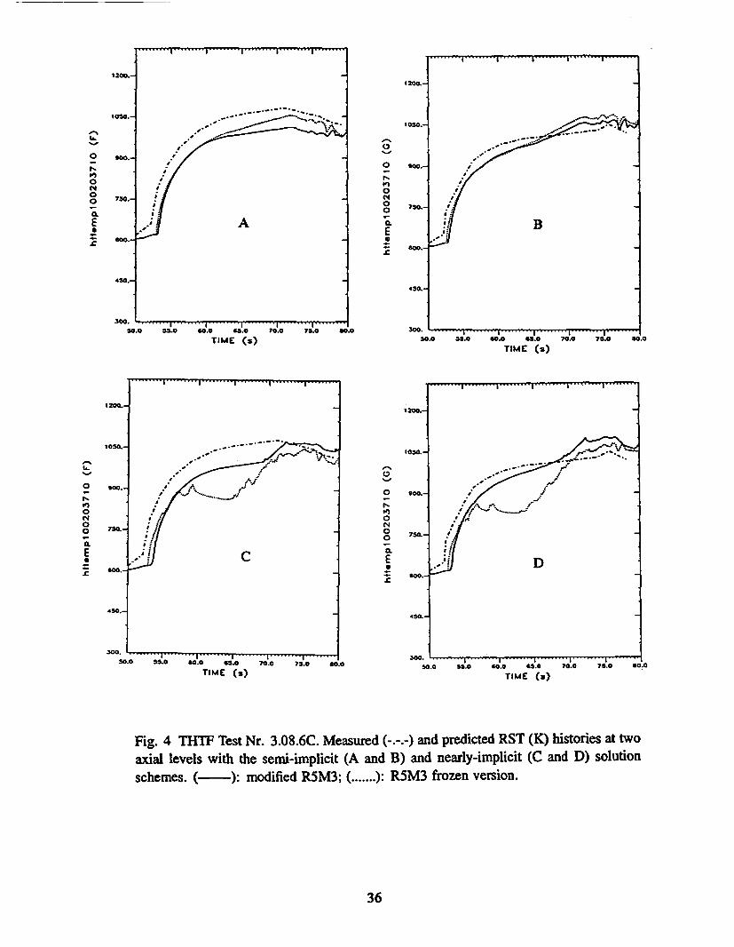
........ ] ......... I ......... d ......... i-I ....... & .........
tOSO.-
200.-0
00
a.ESr
00
0
N
00
0.EU
B
600.-
4 50.j
S0.0 SS.0 60.0 65.0 70.0 75.0 8
TIME (s)TIME (s).0
0N'00
0.EU=
0
0
0
00
0.E
TIME (3)
Fig. 4 THTF Test Nr. 3.08.6C. Measured (-.-.-) and predicted RST (K) histories at two
axial levels with the semi-implicit (A and B) and nearly-implicit (C and D) solution
schemes. (- ): modified R5M3; ( ....... ): R5M3 frozen version.
36
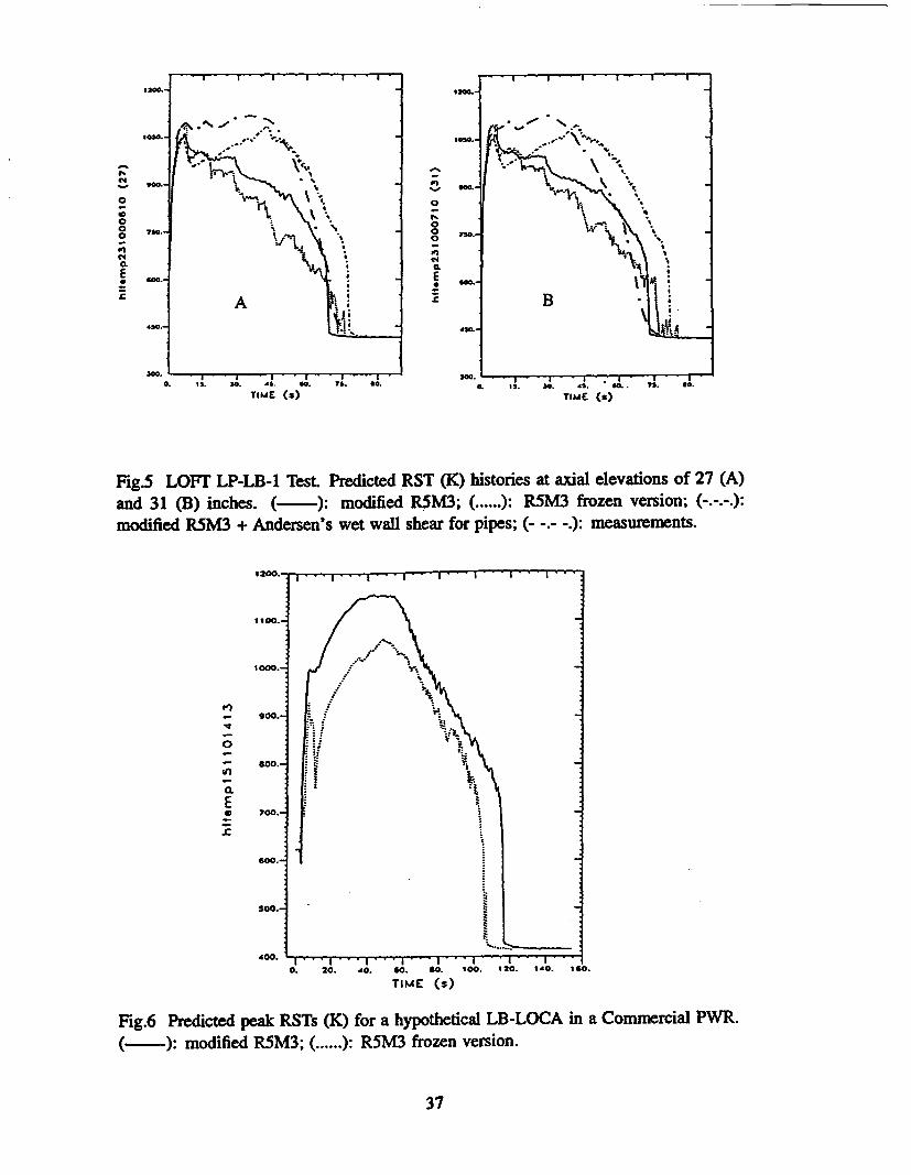
-" ,, -.
o '4 . 0- \4'1.4 g 0U
AA B3
30.. 3W
0. -,I.s . , . , . ,. ,,.TiME (s) TIME (s)
Fig.5 LOFT LP-LB-1 Test. Predicted RST (K) histories at axial elevations of 27 (A)and 31 (B) inches. (- ): modified R5M3; ( ...... ): R5M3 frozen version; (-.-.-.):modified R5M3 + Andersen's wet wall shear for pipes; (- -.- -.): measurements.
1200. , . - I . II * " " I - " - I I i , • •
1100.-
1000.-
GOO.-
700.-
0
U,
a.
E
600.-
SOO.-
I I I4000. 20. 40. 60. 80.
TIME (s)
I 1 I100, 120. 140. 140.
Fig.6 Predicted peak RSTs (K) for a hypothetical LB-LOCA in a Commercial PWR.(- ): modified RSM3; ( ...... ): R5M3 frozen version.
37
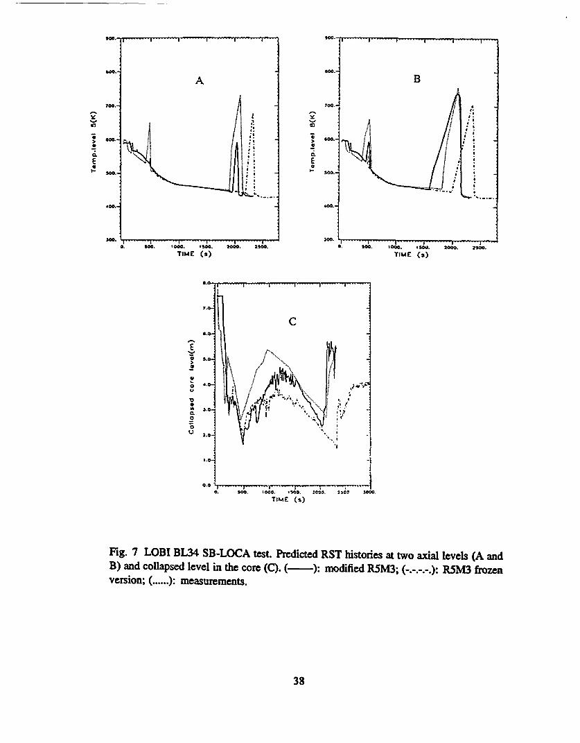
700.-
Fn
E
- I I -
A
A
0
U
0.
ECI-
600. -
5010.!
ADD.-
. .300. i .. . .I . . . . . . -. . . I . . . . . I . . . . . ! . .
0. S0M '000. SO. 2000. 2500.
TIME (s)
+
S0M. 1000. 1500. 2000. 2SO0.
TIME (s)
n ý
a.0 .
0.
0U)
6.0-
5.0-.
3.0-
2.0--
1.0-
0.0 I0. S00- 100. 1500. 2C00 2502 3000.
TIME Cs)
Fig. 7 LOBI BL34 SB-LOCA test. Predicted RST histories at two axial levels (A andB) and collapsed level in the core (C). (): modified R5M3; (-.-.-.-.): R5M3 frozenversion; ( ...... ): measurements.
38
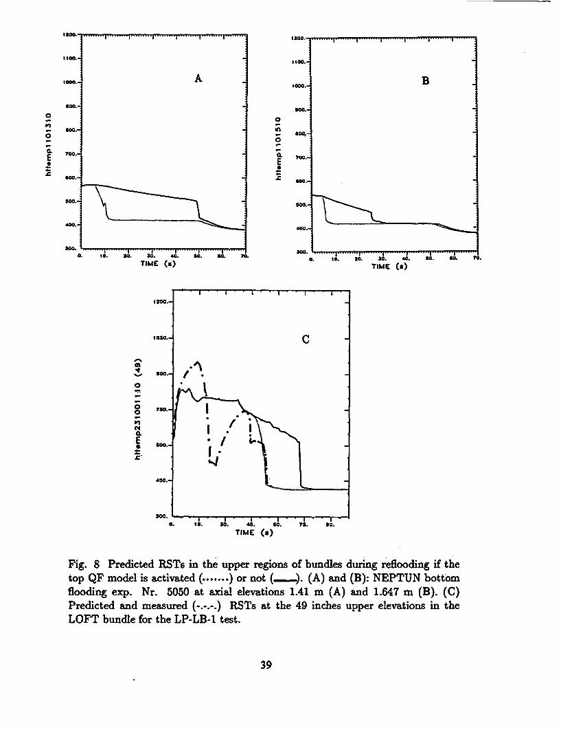
i'W . ......... | ......... | ......... | ......... | ......... | ......... I ........
0
I',
0
a.ES
£
t000o
£00.-
@W0.
700.
600.-
400.
30....... I ......... i ..... I0. 1O. 20. 30. 40.
TIME (a)
1050.
to00.-
0
S 750.0
C4E * 00.
A
0
0
a.E
1000 B
M O0.-
tOO.- T
300o
£100,
o00.-
I I S S S,O 60 i0. to. 30. 30. 40. 99. £0. 10.
TIME (S)
Fig. 8 Predicted RSTs in the upper regions of bundles during reflooding if thetop QF model is activated (.+....... ) or not (_ ). (A) and (B): NEPTUN bottomflooding exp. Nr. 5050 at axial elevations 1.41 m (A) and 1.647 m (B). (C)Predicted and measured (-.-.-.) RSTs at the 49 inches upper elevations in theLOFT bundle for the LP-LB-1 test.
39


NRC FORM 335 U.S. NUCLEAR REGULATORY COMMISSION 1. REPORT NUMBER
(2419) (Assigned by NRC. Add Vol., Supp., Rev.NRCM 110Z, and Addendum Numbers. If any.)
M. 3 BIBUOGRAPHIC DATA SHEET(See h•abwctona a• #~e ,,v-ae)
2. TITLE AND suTTrnLE NUREG/AA-0140
Development Assessment of RELAP5/MOD3.1 withSeparate-Effect and Integral Test Experiments: 3. DATE REPORT PUBLISHED
Model Changes and Options MONTH Y
October 19984. FIN OR GRANT NUMBER
W62385. AUTHOR(S) 6. TYPE OF REPORT
G. Th. Anelytis Technical
7. PERIOD COVERED enousive Dates)
8. PERFORMING ORGANIZATION -NAME AND ADDRESS (AfWr, pwve Diviokn OfcerRegicn. U.S. McM Re g&yCommias~wi an maing •9 lna•.a•r.
pmvide, name and nmain oddfesa
Laboratory for Thermal HydraulicsPaul Scherrer InstituteCH-5232 Villigen PSISwitzerland
O. SPONSORING ORGANIZATION - NAME AND ADDRESS pr Nm_, "Smame s •ove; X • b.provide •Div;si oirce a Regko U.S. kc• ftue1*y/ornaomsi~iand maing addess.)
Office of Nuclear Regulatory ResearchU.S. Nuclear Regulatory CommissionWashington, DC 20555-0001
10. SUPPLEMENTARY NOTES
J. Uhle, NRC Project Manager11. ABSTRACT = wrds orins)
A summary of modifications and options introduced in RELAP5/MOD3.1 (R5M3.1) is presented and is shown that the predictingcapabilities of the modified version of the code are greatly Improved, while the general philosophy we followed In arriving at thesemodifications Is also outlined. These changes which are the same ones we implemented In the past version 7j of the code,include 2 different heat transfer packages (one of them activated during reflooding), modification of the low mass-flux GroeneveldCHF look-up table and of the dispersed flow interfacial area (and shear) as well as of the criterion for transition Into and out fromthis regime, almost complete elimination of the under-relaxation schemes of the interfacial closure coefficients etc. The modifiedR5M3.1 code is assessed against a number of separate-effect and Integral test experiments and in contrast to the frozen version, isshown to result In physically sound predictions which are much closer to the measurements, while almost all the predicted variablesare free of unphysical spurious oscillations. The modifications Introduced solve a number of problems associated with the frozenversion of the code and result in a version which can be confidently used for both SB-LOCA and LB-LOCA analyses.
12. KEY WORDOSDESCRIPTORS #Ast words orphraaas £ft wE assst rosewrhars l hft e 13. AVAILABILITY STATEMENT
RELAP5/MOD3.1 unlimitedSB-LOCA 14. SECURITY CLASSIFRCATION
LB-LOCA (1 P,,)unclassified
(TIs Repo-l
unclassified15. NUMBER OF PAGES
16. PRICE
NRC FORM 335 (2-9)

Federal Recycling Program


NUREGIIA-0140 DEVELOPMENTAL ASSESSMENT OF RELAP5/MOD3.1 WITHSEPARATE-EFFECT AND INTEGRAL TEST EXPERIMENTS: MODEL CHANGES AND OPTIONS
OCTOBER 1998
UNITED STATESNUCLEAR REGULATORY COMMISSION
WASHINGTON, DC 20555-0001
MRST CLASS MAILPOSTAGE AND FEES PAID
USNRCPERMIT NO. G-7
OFFICIAL BUSINESSPENALTY FOR PRVATE USE, $300