nutrient delivery system - hydrobuilder.com
TRANSCRIPT

Chat at www.dilutionsolutions.com
Nutrient Delivery System
Need Help?Call 1-800-451-6628
LO-FLO SERIES
3/4” Kits Assembly Instructions

Need help? Call 1-800-451-6628
Nutrient Delivery SystemCongratulations on your Dilution Solutions
NOTE: Installation illustrations are to be used as a reference guide only.
NDS Quick Start-Up Guide
The Nutrient Delivery System (NDS) is a simplistic system made up of four main panel sections which can be arranged to accommodate a wide variety of fertigation programs. With total control in mind, customizing the entire panel is easy based on your personal nutrient program. It provides increased quality, along with making the process of blending and dispensing nutrients easier and more accurate!
Tools required for installation of Kit or Pre-Plumbed Assembled System:l Drilll Level
l Screwdriversl Plumbing wrench
l Mounting fasteners (panels)l Pipe hangers (kits)

Chat at www.dilutionsolutions.com
Panels or Kits Order Part NumberBooster Pump Starter Kit HYKSTART-DAB
Unit Expansion Kit (Dosatron) Varies depending on dilution rates
Mixing Chamber Kit HYKMC34
Unit Expansion Kit (Dosatron) Varies depending on dilution rates
Nutrient Monitor with Mixing Chamber Kit HYKMON
Water Hammer Arrestor Kit WHA34-SS-KIT
NDS Quick Start-Up Guide
1
Installation TipsThe Pre-Plumbed System or Kit must be mounted securely to a wall that can hold up to 100 pounds. If your setup has a nutrient monitor component, a power outlet must be nearby. Remember that water and power don’t mix well; be sure the outlet will not get wet. Mount the outlet above doser panel.Choose appropriate mounting fasteners and pipe hangers based on the wall material and follow the manufacturer’s instructions for use.It will take two people to hold, level the Panels or Kits, and mount them to the wall.Prior to mounting the Panels or Kits, lay them out in your desired order (example):
Mount the Panels or Kits 4 to 5 feet above the floor.Never mount Dosatron’s inlet and outlet below the top of the concentrate barrel.If you have a pre-plumbed system, you will have to unwrap the unitsand snap the Dosatron Dosers into the brackets on the panel.Connect the Dosatron Dosers and unions to each other.Place the concentrate containers directly below the panels.Each Dosatron Doser includes a 6’ suction tube, but you can special order up to 13’ per Doser if necessary.

Need help? Call 1-800-451-6628
NDS Quick Start-Up Guide
Assembly is required for Nutrient Delivery System Kits:
Refer to assembly instructions starting on page 6.l DAB Starter Kit (page 6)l Standard Starter Kit (page 9)l Mixing Chamber Kit (page 12)l Monitor Kit (page 13) l Water Hammer Arrestor Kit (page 17)
2
Connection Start-Up & TipsIf you have a monitor, make sure you calibrate the pH probe before you install into the line (refer to the manual for calibration of the monitor).Connect the water supply to the system’s inlet and connect the system’s discharge to your irrigation system. Make sure to use Teflon® tape on the threads to prevent leaks. DO NOT USE PIPE DOPE.Connect the suction tubes to each Dosatron Doser.Slide the strainer on each tube and drop into the concentrate containers.Prior to turning the water on, double check that all of the gray unions are tight and the clear water and flush port ball valves are closed.Slowly turn on the water — DO NOT turn valve on quickly.The Dosatron dosers will begin to make a clicking sound. This is normal while the system is filling with water.The Dosatron dosers will click-clack when the system is in use.The nutrient monitor may take a little time to stabilize. There will be odd readings on the EC until the system is primed.Use the last “test port” on the system for measuring the final solution or as you fill the system and prime the dosers.By using a hose or bucket under the port, you can keep the area dry and it is a good way of capturing the product as you prime.When priming the system, set the Dosatrons to the highest dilution to speed up the process. Then utilize the bypass switches to turn off each unit when the concentrate reaches the injection stem in order to minimize waste.
Chat at www.dilutionsolutions.com
NDS Quick Start-Up Guide
3
Use the conversion chart (located on page 21) and dial in each Dosatron to the desired injection rate.Using % is the most effective way to convert mL/tsp to % or ratio.The bypass switch on the top of each Dosatron Doser allows you to turn the injection on and off for each unit.The test port after the monitor allows you to take a sample and manually check your EC/pH, to make sure your monitor is properly functioning, to perform volumetric tests, flush the system out, etc.(Find links in Resources page 21.)Do not leave probes dry for long periods of time. Store in KCL Solution if the system goes out of commission.
Usage Tips
Dosatron’s are designed to dose accurately with repeatable results, like most mechanical devices they need regular maintenance.If you notice a lag in performance, it is as simple as replacing a few wear parts.Over a period of time and use, the dynamic seals will wear, causing low injection.Typical wear pattern is 6 to 12 months of continual use, maintenance is suggested on a yearly schedule or when the product is not functioning properly.(Please see references on page 20, for further details.)
Maintenance Tips
Turn the system off, then go back to each Dosatron and set the injection stem to the proper amount to be dispensed.After all Dosatrons are set and primed, turn on the bypass switch to each unit and let the system run. Within a short period of time, the final solution will be ready to use and the monitor will display the desired output.

Need help? Call 1-800-451-6628
Nutrient Delivery System
Standard Starter Kit
Mixing Chamber Kit
2
4
Booster Pump Starter Kit
NOTE: Installation
illustrations are to be used
as a reference guide only.
1
Option A Option B
LO-FLO Series - 3/4” Kits
Part #: HYKSTART
Part #: HYKSTART-DAB
Part #:HYKMC34
1
1
2
Chat at www.dilutionsolutions.com
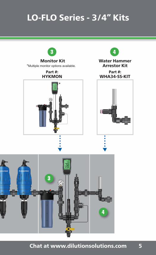
Monitor Kit Water HammerArrestor Kit
3 4
5
LO-FLO Series - 3/4” Kits
Part #: HYKMON
Part #: WHA34-SS-KIT
3
4
*
*Multiple monitor options available.

Need help? Call 1-800-451-66286
1 Option A
Part #: HYKSTART-DAB(Does not include the
Pressure Boosting Pump)
3/4” Booster Pump Starter Kit
Wrap 5 to 6 turns of Teflon® tape on all threads, except on the Pressure Gauge (2-3 turns only). Make sure to wrap tape clockwise to prevent from unravelling.
With the arrow pointing down, attach the Y Filter to the other end of the Banjo® Ball Valve.
Attach an Elbow to one of the Banjo® Ball Valves.
1
2
3
NOTE: Installation illustrations are to be used as a reference guide only.
HYKSTART-DAB Kit is to be used with any Booster Pump that regulates the pressure (not to exceed 85 psi). If the pump being
installed does not regulate the pressure to the system specifications, a regulator is necesary.
3/4” Booster Pump Starter Kit Step-by-Step Assembly Instructions

Chat at www.dilutionsolutions.com 7
3/4” Booster Pump Starter Kit Step-by-Step Assembly Instructions
Connect the Cross to the other end of the Filter.
Insert the 3/4” to 1/4” Reducer Nipple and the Pressure Gauge to the opening on the left of the Cross.
Attach one Nipple on each of the openings left on the Cross.
Connect the remaining Banjo® Ball Valve to the Nipple at the bottom of the Cross.
Attach the Hose Adapter to the Banjo® Ball Valve.
Connect a second Elbow to the Nipple on the right of the Cross.
4
6
8
5
7
9

Need help? Call 1-800-451-66288
Attach the Check Valve to the Elbow, make sure the arrow points up.
Connect the third Elbow to the Check Valve.
Attach the Union to the Nipple. This completes the HYKSTART-DAB Kit.
Attach the last Nipple to the Elbow.
Part Number Qty Part Number QtyHS34SE-FPXMP 3 NIP075-2 3BV34-SCH80 2 E34-BR 1AKF5AP11-A 1 CV34-PH 1CRO75 1 BK034-U 1RB75-25T 1 TEF12 1PG100 1
HYKSTART-DAB Kit Includes:
Pressure Booster Starter Kit includes parts listed. Dosatron doser and pressure boosting pump sold separately.
10
12
11
13
Don’t forget to wrap the connectors on the Dosatron with Teflon® tape.

Chat at www.dilutionsolutions.com 9
1 Option B
3/4” Standard Starter Kit Step-by-Step Assembly Instructions
Wrap 5 to 6 turns of Teflon® tape on all threads. Make sure to wrap tape clockwise to prevent from unravelling.
Connect a Nipple to each side of the Pressure Regulator and set aside.
Pick up one of the Elbows and connect it to a Banjo® Ball Valve. With the arrow
facing down, connect the Y Filter to the Banjo® Ball Valve.
1
3
2
4
3/4” Standard Starter Kit
Part #: HYKSTART(Includes Pressure Regulating Valve)
NOTE: Installation illustrations are to be used as a reference guide only.
Attach the Check Valve to the Elbow, make sure the arrow points up.
Connect the third Elbow to the Check Valve.
Attach the Union to the Nipple. This completes the HYKSTART-DAB Kit.
Attach the last Nipple to the Elbow.

Need help? Call 1-800-451-662810
Add the Female Coupler to the other end of the Y Filter.
Attach the Pressure Regulator assembly to the Female Coupler, make sure the arrow faces down.
Connect the Tee to the other end of the Pressure Regulator assembly.
Insert a Nipple on each of the two openings left on the Tee.
Attach the Banjo® Ball Valve to the bottom Nipple and connect the Hose Adapter to the Banjo® Ball Valve.
Attach an Elbow to the Nipple in the center of the Tee.
5
7
9
6
8
10

Chat at www.dilutionsolutions.com
With the arrow facing up, connect the Check Valve to the Elbow.
Attach the last Elbow to the top of the Check Valve.
Now attach your Dosatron Doser to the Union.
Insert a Nipple into the Elbow and attach the Union to the Nipple.
11
11
13
12
14
Part Number Qty Part Number QtyHS34SE-FPXMP 3 TT34 1BV34-SCH80 2 E34-BR 1AKF5AP11-A 1 CV34-PH 1FC34 1 BK034-U 1NIP075-2 5 TEF12 1PR34-NPT 1
HYKSTART Kit Includes:
Standard Starter Kit includes parts listed. Dosatron doser sold separately.
Add the Female Coupler to the other end of the Y Filter.
Attach the Pressure Regulator assembly to the Female Coupler, make sure the arrow faces down.
Connect the Tee to the other end of the Pressure Regulator assembly.
Insert a Nipple on each of the two openings left on the Tee.
Attach the Banjo® Ball Valve to the bottom Nipple and connect the Hose Adapter to the Banjo® Ball Valve.
Attach an Elbow to the Nipple in the center of the Tee.
Don’t forget to wrap the connectors on the Dosatron with Teflon® tape.

Need help? Call 1-800-451-6628
3/4” Mixing Chamber Kit Step-by-Step Assembly Instructions
Wrap 5 to 6 turns of Teflon® tape on all threads. Make sure to wrap tape clockwise to prevent from unravelling.
With the arrow on the Mixing Chamber pointing in the direction of the water flow, install the Union onto the Nipple in the outlet.
Insert one Nipple on each side of the Mixing Chamber.
1
2
3
Part Number QtyNIP075-2 2MC34 1BK034-U 1TEF12 1
HYKMC34 Kit Includes:
Mixing Chamber Kit includes parts listed.
Dosatron dosersold separately.
3/4” Mixing Chamber KitPart #: HYKMC34
12
NOTE: Installation illustrations are to be used as a reference guide only.
2

Chat at www.dilutionsolutions.com
3/4” Monitor KitPart #: HYKMON
3/4” Monitor Kit Step-by-Step Assembly Instructions
Wrap 5 to 6 turns of Teflon® tape on all threads, except on the Pressure Gauge (2-3 turns only). Make sure to wrap tape clockwise to prevent from unravelling.
Attach a Close Nipple to each side of the Mixing Chamber.
1
2
13
NOTE: Installation illustrations are to be used as a reference guide only.
3
*
*Multiple monitor options available.
Need help? Call 1-800-451-6628
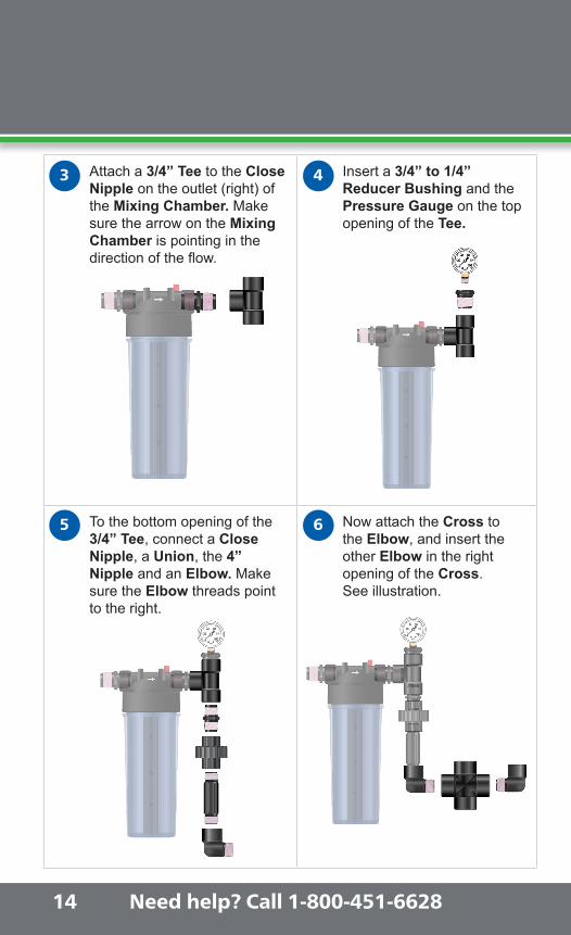
Attach a 3/4” Tee to the Close Nipple on the outlet (right) of the Mixing Chamber. Make sure the arrow on the Mixing Chamber is pointing in the direction of the flow.
Insert a 3/4” to 1/4” Reducer Bushing and the Pressure Gauge on the top opening of the Tee.
To the bottom opening of the 3/4” Tee, connect a Close Nipple, a Union, the 4” Nipple and an Elbow. Make sure the Elbow threads point to the right.
Now attach the Cross to the Elbow, and insert the other Elbow in the right opening of the Cross.See illustration.
3 4
14
5 6

Chat at www.dilutionsolutions.com
To the bottom of the Cross, attach a Close Nipple, the Banjo® Ball Valve, and the Hose Adapter.
To the Elbow on the right, attach a Reducer Nipple, the 1” Tee, and the other Reducer Nipple, in that particular order.
Connect the 3/4” Tee, a Close Nipple, the Check Valve (make sure arrow points down), and the Barb Fitting to the Reducer Nipple.
Attach the last Close Nipple and the Union to the middle opening of the 3/4” Tee.
8
109
7
15

Need help? Call 1-800-451-6628
Now, remove the plastic casing** from Monitor pH probe and follow calibration instructions provided with the monitor. Attach both probes to the Probe Holder Assembly as shown.For more details see the Monitor instructions.
Part Number Qty Part Number QtyMC34 1 CV34-PH 1BV34-SCH80 1 BARB037-075MP 1HS34SE-FPXMP 2 BK034-U 2X500-105 1 CR075 1NIP075-2 6 TEF12 1PG100 1 E34-BR 1TT34 2 RN100-75 2NIP75-4 1 TT100 1RB75-25T 1
HYKMON Kit Includes:
Monitor Kit includes parts listed. Dosatron doser sold separately.
11
NOTE: Regular cleaning and calibration, of the probes, is recomended to obtain accurate readings. Probes are maintenance items and would require replacing from time to time.
16
**Casing keeps probe wet, maintaining calibration until installation.
*Multiple monitor options available.
*
Chat at www.dilutionsolutions.com
Now, remove the plastic casing** from Monitor pH probe and follow calibration instructions provided with the monitor. Attach both probes to the Probe Holder Assembly as shown.For more details see the Monitor instructions.
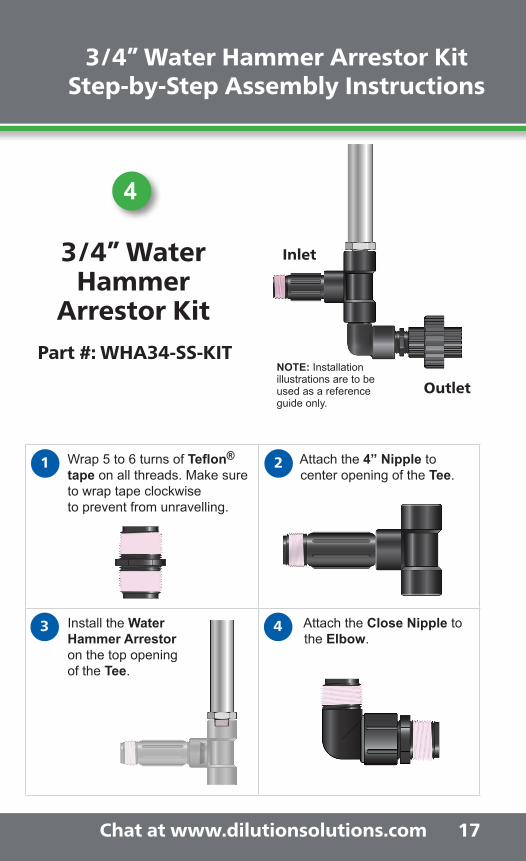
Wrap 5 to 6 turns of Teflon® tape on all threads. Make sure to wrap tape clockwise to prevent from unravelling.
Attach the 4” Nipple to center opening of the Tee.
Install the Water Hammer Arrestor on the top opening of the Tee.
Attach the Close Nipple to the Elbow.
3/4” Water Hammer Arrestor Kit Step-by-Step Assembly Instructions
Inlet
Outlet
1
3
2
4
3/4” Water Hammer
Arrestor KitPart #: WHA34-SS-KIT
17
NOTE: Installation illustrations are to be used as a reference guide only.
4
Need help? Call 1-800-451-6628
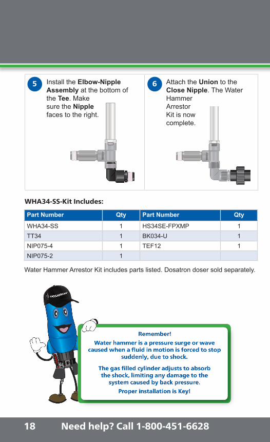
Install the Elbow-Nipple Assembly at the bottom ofthe Tee. Make sure the Nipple faces to the right.
Attach the Union to the Close Nipple. The Water Hammer Arrestor Kit is now complete.
5 6
Part Number Qty Part Number Qty
WHA34-SS 1 HS34SE-FPXMP 1TT34 1 BK034-U 1NIP075-4 1 TEF12 1NIP075-2 1
WHA34-SS-Kit Includes:
Water Hammer Arrestor Kit includes parts listed. Dosatron doser sold separately.
18
Recommended Dosatron Dosers For the 3/4” NDS Kits

Chat at www.dilutionsolutions.com
Install the Elbow-Nipple Assembly at the bottom ofthe Tee. Make sure the Nipple faces to the right.
Attach the Union to the Close Nipple. The Water Hammer Arrestor Kit is now complete.
19
Nutrient Delivery System 3/4” Kits Dosatron Dosers
D14MZ2VFBPHY D14MZ3000VFBPHY(*D14MZ3000VFBPHY-M)
D14MZ10VFBPHY D25RE09VFBPHY(*D25RE09VFBPHY-M)
Recommended Dosatron Dosers For the 3/4” NDS Kits
NOTE: Each unit comes with a single union to connect to the next unit or kit. Dosatron dosers sold separately.
14 GPM1:500 - 1:50
14 GPM1:3000 - 1:333
14 GPM1:100 - 1:10
11 GPM1:1000 - 1:112
*Units available with metric system scale.

Need help? Call 1-800-451-6628
DIY - Do-It-Yourself Maintenance Kits Resources
We make it easy to keep your Dosatron running smoothly year after year with our Seal Kits and Mini Maintenance Kits. Recommended maintenance parts are included in the Kits, along with easy-to-follow instructions. To order call 1-800-523-8499.
Mini Maintenance Kits - A simple and cost effective way to keep your Dosatrons running smooth and accurately.
Description Part #
D25RE09 - 11 GPM PJ127MINI-H
D14MZ2 - 14 GPM PJDI116MINI-H
D14MZ10 - 14 GPM PJDI122MINI-H
D14MZ3000 - 14 GPM PJDI139MINI
D8RE3000 - 40 GPM PJDI139MINI
D8RE2 - 40 GPM PJDI120VMINI-H
Part PJ127MINI-H:D25RE09 - 11 GPM Mini Maintenance Kit
This kit contains:
(1) JDI106 Dosing seal
(1) PJDI063Upper check valve assembly
(1) DOSA-LUBE Silicone
(1) CLEANSER ALL Dosa-Klean
2090 Sunnydale Blvd.Clearwater, FL 33765
1-800-523-8499 1-727-443-5404
www.dosatronusa.com
20
Seal Kits - If your Dosatron hasn’t been serviced in a few years, or it is leaking, it’s time for a full seal kit maintenance.
Description Part #
D25RE09 - 11 GPM PJ127
D14MZ2 - 14 GPM PJDI116
D14MZ10 - 14 GPM PJDI122
D14MZ3000 - 14 GPM PJDI139
D8RE2 - 40 GPM PJDI120
D8RE5 - 40 GPM PJDI122V
D8RE3000 - 40 GPM 8PJ075
Part PJDI116:D14MZ2 - 14 GPM Injection Seal Kit
(1) J009 Plunger seal(1) JDI120 Injection stem
o-ring
(1) JDI100 Injection sleeve o-ring
(1) PJDI115 Check valve assembly
This kit contains:
2090 Sunnydale Blvd.Clearwater, FL 33765
1-800-523-8499 1-727-443-5404
www.dosatronusa.com
1
2

Chat at www.dilutionsolutions.com
DIY - Do-It-Yourself Maintenance Kits Resources
MILLILITERS (mL) CONVERSION CHART
Milliliters (mL)
Teaspoons (tsp)
Ounces (oz)
Percentage (%)
Ratio (1:)
34 7 1.1 0.9 112
30 6 1.0 0.79 128
25 5 0.83 0.66 150
20 4 0.67 0.53 190
15 3 0.50 0.40 250
10 2 0.33 0.26 375
5 1 0.17 0.13 750
4 0.8 0.133 0.11 950
3 0.6 0.100 0.08 1250
2.5 0.5 0.09 0.07 1500
2 0.4 0.067 0.05 2000
1.5 0.3 0.05 0.04 2500
1.25 0.25 0.042 0.03 3000
1 0.2 0.033 0.026 3875
Questions?1. Call 1-800-523-84992. Chat with a customer service representative @ www.dosatronusa.com3. Looking for technical help, click charts, volumetric tests, seal kits, unit
schematics, or warranty information? www.dosatronusa.com/technical4. Need more resources? www.dosatronusa.com/nds5. For all videos, from troubleshooting to installing a seal kit, check out our
YouTube channel: www.youtube.com/users/DosatronIntl
Do you want an easy Preventive Maintenance Reminder?• Sign up for free at: www.dosatronusa.com/technical
21

Need help? Call 1-800-451-6628Need help? Call 1-800-451-6628
2090 Sunnydale Blvd. • Clearwater, FL 337651-800-451-6628
www.dilutionsolutions.com