nva-1117-deploy-microsoft exchange 2016, sharepoint …this document focuses on vmware vsphere 6.5,...
TRANSCRIPT

Reviewed by
NetApp Verified Architecture
FlexPod Datacenter with Microsoft Exchange 2016, SharePoint 2016, and NetApp AFF A300 NVA Deployment Glenn Sizemore, Bhavin Shah, NetApp
October 2017 | NVA-1117-DEPLOY | Version 1.0
2 FlexPod Datacenter with Microsof t Exchange 2016, SharePoint 2016,
and NetApp AFF A300 © 2017 NetApp, Inc. All rights reserv ed.
TABLE OF CONTENTS
1 Program Summary ......................................................................................................................5
2 Solution Overview .......................................................................................................................5
2.1 Solution Technology........................................................................................................................................................6
2.2 Use Case Summary ........................................................................................................................................................6
3 Technology Requirements ..........................................................................................................7
3.1 Hardware Requirements.................................................................................................................................................7
3.2 Software Requirements ..................................................................................................................................................8
4 FlexPod Cabling on ONTAP ........................................................................................................8
5 Deployment Procedures ............................................................................................................ 12
5.1 NetApp Storage Configuration.................................................................................................................................... 13
5.2 Cisco UCS Server Configuration................................................................................................................................ 31
5.3 Cisco Nexus Storage Networking Configuration ..................................................................................................... 55
5.4 VMware vSphere Configuration ................................................................................................................................. 62
5.5 VMware vCenter 6.5a Configuration ......................................................................................................................... 69
5.6 NetApp VSC 6.2.1 Deployment Procedure .............................................................................................................. 75
5.7 Service Accounts Creation .......................................................................................................................................... 79
5.8 SQL Server 2016 Installation and Configuration ..................................................................................................... 80
5.9 Microsoft SharePoint 2016 Installation and Configuration ..................................................................................... 97
5.10 DocAve 6 Installation ................................................................................................................................................. 115
5.11 Microsoft Exchange 2016 Installation and Configuration ..................................................................................... 126
5.12 SnapManager for Exchange Installation and Configuration ................................................................................ 157
6 Solution Verification................................................................................................................ 160
6.1 Exchange 2016 Verification ...................................................................................................................................... 160
6.2 SharePoint 2016 Verification .................................................................................................................................... 167
7 Conclusion .............................................................................................................................. 175
Appendix A: LoadGen Configuration ............................................................................................ 176
Configure Outlook Anywhere for LoadGen 2013 Clients...............................................................................................176
Appendix B: SharePoint Load Testing Tools ................................................................................ 177
Sample Tool to Create Large Number of Random Documents ....................................................................................177
Sample Tool to Load Documents into SharePoint ..........................................................................................................177
Sample Code for SharePoint Performance Testing .......................................................................................................178

3 FlexPod Datacenter with Microsof t Exchange 2016, SharePoint 2016,
and NetApp AFF A300 © 2017 NetApp, Inc. All rights reserv ed.
Where to Find Additional Information ........................................................................................... 178
Cisco UCS .............................................................................................................................................................................178
Cisco Nexus Networking .....................................................................................................................................................178
NetApp AFF Storage............................................................................................................................................................178
VMware vSphere ..................................................................................................................................................................178
Interoperability Matrixes ......................................................................................................................................................179
Version History ............................................................................................................................. 179
LIST OF TABLES
Table 1) Hardware requirements....................................................................................................................................................7
Table 2) Software requirements. ....................................................................................................................................................8
Table 3) Cisco Nexus 9396PX A cabling information. ................................................................................................................9
Table 4) Cisco Nexus 9396PX B cabling information. ............................................................................................................. 10
Table 5) NetApp controller A cabling information. .................................................................................................................... 11
Table 6) NetApp controller B cabling information. .................................................................................................................... 11
Table 7) Cisco UCS fabric interconnect A cabling information............................................................................................... 11
Table 8) Cisco UCS fabric interconnect B cabling information............................................................................................... 12
Table 9) Cluster details for the ONTAP software configuration. ............................................................................................ 14
Table 10) Cluster details for the cluster-join operation. ........................................................................................................... 18
Table 11) iSCSI LIFs for iSCSI IQN............................................................................................................................................ 55
Table 12) vNIC iSCSI IQNs for fabric A and fabric B. .............................................................................................................. 55
Table 13 ) Service user accounts................................................................................................................................................ 79
Table 14) Service user groups..................................................................................................................................................... 80
Table 15) SQL Server 2016: VM configuration parameters.................................................................................................... 80
Table 16) SQL primary site storage. ........................................................................................................................................... 83
Table 17) SharePoint 2016: VM configuration parameters..................................................................................................... 98
Table 18) DocAve 6: VM configuration parameters. .............................................................................................................. 115
Table 19) SQL primary site storage. ......................................................................................................................................... 119
Table 20) Database distribution................................................................................................................................................. 126
Table 21) Microsoft Exchange 2016: VM configuration parameters. .................................................................................. 128
Table 22) Exchange LUN reference. ........................................................................................................................................ 131
Table 23) External URL configuration information. ................................................................................................................ 143
Table 24) Databases on Exchange mailbox servers. ............................................................................................................ 152
Table 25) Exchange performance results. .............................................................................................................................. 166
Table 26) Workload characteristics........................................................................................................................................... 167
Table 27) Applied workload (100 RPH) on the created SharePoint farm. .......................................................................... 169

4 FlexPod Datacenter with Microsof t Exchange 2016, SharePoint 2016,
and NetApp AFF A300 © 2017 NetApp, Inc. All rights reserv ed.
LIST OF FIGURES
Figure 1) FlexPod component families..........................................................................................................................................5
Figure 2) FlexPod Datacenter for Microsoft Exchange 2016 and Microsoft SharePoint 2016 solution topology. ............7
Figure 3) FlexPod cabling diagram for use case on ONTAP. ....................................................................................................9
Figure 4) Cabling diagram for NetApp storage with NetApp disk shelves............................................................................ 14
Figure 5) Exchange LoadGen 2013 configuration summary. ............................................................................................... 161
Figure 6) Results for LoadGen host 1. ..................................................................................................................................... 162
Figure 7) Results for LoadGen host 2. ..................................................................................................................................... 162
Figure 8) Results for LoadGen host 3. ..................................................................................................................................... 163
Figure 9) Results for LoadGen host 4. ..................................................................................................................................... 163
Figure 10) Results for LoadGen host 5. ................................................................................................................................... 164
Figure 11) Results for LoadGen host 6. ................................................................................................................................... 164
Figure 12) Results for LoadGen host 7. ................................................................................................................................... 165
Figure 13) Results for LoadGen host 8. ................................................................................................................................... 165
Figure 14) Processor utilization. ................................................................................................................................................ 166
Figure 15) Memory utilization..................................................................................................................................................... 167
Figure 16) HTTP throttling: off mode. ....................................................................................................................................... 168
Figure 17) SharePoint web front-end processor utilization. .................................................................................................. 170
Figure 18) SharePoint application server processor utilization. ........................................................................................... 170
Figure 19) SharePoint search server processor utilization. .................................................................................................. 171
Figure 20) SQL Server processor utilization. .......................................................................................................................... 171
Figure 21) Network utilization. ................................................................................................................................................... 172
Figure 22) Memory utilization..................................................................................................................................................... 172
Figure 23) Average read latency. .............................................................................................................................................. 173
Figure 24) Average write latency............................................................................................................................................... 174
Figure 25) Average CPU utilization........................................................................................................................................... 174
Figure 26) Total storage operations.......................................................................................................................................... 175
Figure 27) Average latency. ....................................................................................................................................................... 175
5 FlexPod Datacenter with Microsof t Exchange 2016, SharePoint 2016,
and NetApp AFF A300 © 2017 NetApp, Inc. All rights reserv ed.
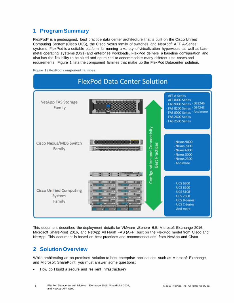
1 Program Summary
FlexPod® is a predesigned, best practice data center architecture that is built on the Cisco Unified
Computing System (Cisco UCS), the Cisco Nexus family of switches, and NetApp® AFF A-Series
systems. FlexPod is a suitable platform for running a variety of virtualization hypervisors as well as bare-
metal operating systems (OSs) and enterprise workloads. FlexPod delivers a baseline configuration and
also has the flexibility to be sized and optimized to accommodate many different use cases and
requirements. Figure 1 lists the component families that make up the FlexPod Datacenter solution.
Figure 1) FlexPod component families.
This document describes the deployment details for VMware vSphere 6.5, Microsoft Exchange 2016,
Microsoft SharePoint 2016, and NetApp All Flash FAS (AFF) built on the FlexPod model from Cisco and
NetApp. This document is based on best practices and recommendations from NetApp and Cisco.
2 Solution Overview
While architecting an on-premises solution to host enterprise applications such as Microsoft Exchange
and Microsoft SharePoint, you must answer some questions:
• How do I build a secure and resilient infrastructure?

6 FlexPod Datacenter with Microsof t Exchange 2016, SharePoint 2016,
and NetApp AFF A300 © 2017 NetApp, Inc. All rights reserv ed.
• How do I make sure of the highest level of availability?
• What return on investment (ROI) can I expect?
• How can I build a future-proof infrastructure?
• How do I reduce the complexity of my infrastructure?
The FlexPod architecture is designed to help you answer all these questions. By introducing
standardization, FlexPod helps you mitigate the risks and uncertainty involved in planning, designing, and
implementing a next-generation data center architecture.
This document focuses on VMware vSphere 6.5, Microsoft Exchange 2016, Microsoft SharePoint 2016,
and NetApp ONTAP® 9.1 built on the FlexPod Datacenter architecture. This document also discusses
design choices and best practices for this shared infrastructure platform. These design considerations
and recommendations are not limited to the specific releases of the components described in this
document but are also applicable to other versions.
2.1 Solution Technology
FlexPod is a best practice data center architecture that includes three core components:
• Cisco UCS
• Cisco Nexus switches
• NetApp AFF or FAS systems
These components are connected and configured according to the best practices of both Cisco and
NetApp and provide the ideal platform for running a variety of enterprise workloads with confidence.
FlexPod can scale up for greater performance and capacity (adding compute, network, or storage
resources individually as needed). It can also scale out for environments that need multiple consistent
deployments (rolling out additional FlexPod stacks). FlexPod delivers a baseline configuration, and it can
also be sized and optimized to accommodate many different use cases.
Typically, the more scalable and flexible a solution is, the more difficult it becomes to maintain a single
unified architecture capable of offering the same features and functionality across implementations. This
is one of the key benefits of the FlexPod architecture. Each of the component families shown in Figure 1
offers platform and resource options to scale the infrastructure up or down while supporting the same
features and functionality that are required under the configuration and connectivity best practices of the
FlexPod solution.
The FlexPod solution addresses four primary design principles: availability, scalability, flexibility, and
manageability, as follows:
• Application availability. Services are accessible and ready to use.
• Scalability. Increasing demands are addressed with appropriate resources.
• Flexibility. New services are provided and resources are recovered without infrastructure
modification requirements.
• Manageability. Efficient infrastructure operations are facilitated through open standards and
application programming interfaces (APIs).
2.2 Use Case Summary
The FlexPod Datacenter with Microsoft Exchange 2016 and Microsoft SharePoint 2016 solution
architecture provides a flexible framework for the following use cases:
• Deploying a solution to run Exchange and SharePoint on a single FlexPod platform
• Architecting a SharePoint farm for 10,000 active users
• Architecting an Exchange environment for 10,000 active users with 5GB mailboxes
7 FlexPod Datacenter with Microsof t Exchange 2016, SharePoint 2016,
and NetApp AFF A300 © 2017 NetApp, Inc. All rights reserv ed.
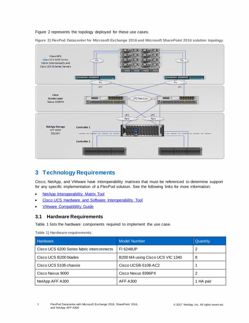
Figure 2 represents the topology deployed for these use cases.
Figure 2) FlexPod Datacenter for Microsoft Exchange 2016 and Microsoft SharePoint 2016 solution topology.
3 Technology Requirements
Cisco, NetApp, and VMware have interoperability matrixes that must be referenced to determine support
for any specific implementation of a FlexPod solution. See the following links for more information:
• NetApp Interoperability Matrix Tool
• Cisco UCS Hardware and Software Interoperability Tool
• VMware Compatibility Guide
3.1 Hardware Requirements
Table 1 lists the hardware components required to implement the use case.
Table 1) Hardware requirements.
Hardware Model Number Quantity
Cisco UCS 6200 Series fabric interconnects FI 6248UP 2
Cisco UCS B200 blades B200 M4 using Cisco UCS VIC 1340 8
Cisco UCS 5108 chassis Cisco UCSB-5108-AC2 1
Cisco Nexus 9000 Cisco Nexus 9396PX 2
NetApp AFF A300 AFF A300 1 HA pair

8 FlexPod Datacenter with Microsof t Exchange 2016, SharePoint 2016,
and NetApp AFF A300 © 2017 NetApp, Inc. All rights reserv ed.
Hardware Model Number Quantity
NetApp DS224C disk shelves Disk shelves populated with 3.8TB SSDs 2 shelves with 24 drives each
3.2 Software Requirements
Table 2 lists the software components required to implement the use case.
Table 2) Software requirements.
Software/Firmware Version
Compute
Cisco UCS Manager 3.1(3a)
Networking
Cisco NX-OS 7.0(3)I4(6)
Storage
NetApp ONTAP 9.1
NetApp VSC 6.2.1
VMware vSphere
VMware ESXi 6.5.0, 4887370
VMware vCenter Server 6.5.0, 4944578
Microsoft SQL Server
Microsoft SQL Server 2016
Microsoft SQL Server Management Studio 16.5.3
Microsoft Apps
Microsoft SharePoint 2016
Microsoft Exchange 2016
Backup and Recovery
DocAve Backup and Restore Version 6 SF9
NetApp SnapDrive® 7.1.4
NetApp SnapManager® for Exchange 7.2
NetApp Single Mailbox Recovery 7.2
4 FlexPod Cabling on ONTAP
Figure 3 illustrates the cabling diagram for this FlexPod use case on ONTAP.

9 FlexPod Datacenter with Microsof t Exchange 2016, SharePoint 2016,
and NetApp AFF A300 © 2017 NetApp, Inc. All rights reserv ed.
Figure 3) FlexPod cabling diagram for use case on ONTAP.
The information provided in Table 3 through Table 8 corresponds to the connections shown in Figure 2.
Table 3) Cisco Nexus 9396PX A cabling information.
Local Device Local Port Connection Remote Device Remote Port Cabling Code
Cisco Nexus 9396PX A
Eth1/1 10GbE Cisco UCS fabric interconnect A
Eth1/31 1

10 FlexPod Datacenter with Microsof t Exchange 2016, SharePoint 2016,
and NetApp AFF A300 © 2017 NetApp, Inc. All rights reserv ed.
Local Device Local Port Connection Remote Device Remote Port Cabling Code
Eth1/2 10GbE Cisco UCS fabric interconnect B
Eth1/31 2
Eth1/3 10GbE Cisco UCS fabric
interconnect A Eth1/29 3
Eth1/4 10GbE Cisco UCS fabric
interconnect B Eth1/29 4
Eth1/5 10GbE NetApp controller A e0e 5
Eth1/6 10GbE NetApp controller B e0e 7
Eth1/7 10GbE NetApp controller A e0g 6
Eth1/8 10GbE NetApp controller B e0g 8
Eth1/47 10GbE Cisco Nexus 9396PX B Eth1/47 17
Eth1/48 10GbE Cisco Nexus 9693PX B Eth1/48 18
MGMT0 1GbE GbE management switch
Any 29
Table 4) Cisco Nexus 9396PX B cabling information.
Local Device Local Port Connection Remote Device Remote Port Cabling Code
Cisco Nexus 9396PX B
Eth1/1 10GbE Cisco UCS fabric interconnect A
Eth1/32 9
Eth1/2 10GbE Cisco UCS fabric interconnect B
Eth1/32 10
Eth1/3 10GbE Cisco UCS fabric interconnect A
Eth1/30 11
Eth1/4 10GbE Cisco UCS fabric interconnect B
Eth1/30 12
Eth1/5 10GbE NetApp controller A e0f 13
Eth1/6 10GbE NetApp controller B e0f 15
Eth1/7 10GbE NetApp controller A e0h 14
Eth1/8 10GbE NetApp controller B e0h 16
Eth1/47 10GbE Cisco Nexus 9396PX A Eth1/47 17
Eth1/48 10GbE Cisco Nexus 9693PX A Eth1/48 18
MGMT0 1GbE GbE management
switch Any 30

11 FlexPod Datacenter with Microsof t Exchange 2016, SharePoint 2016,
and NetApp AFF A300 © 2017 NetApp, Inc. All rights reserv ed.
Table 5) NetApp controller A cabling information.
Local Device Local Port Connection Remote Device Remote Port Cabling Code
NetApp controller A
e0M 1GbE GbE management switch
Any 32
e0c 1GbE GbE management switch
Any 31
e0a 10GbE NetApp controller B e0a 27
e0b 10GbE NetApp controller B e0b 28
e0e 10GbE Cisco Nexus 9396PX A Eth1/5 5
e0f 10GbE Cisco Nexus 9396PX B Eth1/5 13
e0g 10GbE Cisco Nexus 9396PX A Eth1/7 6
e0h 10GbE Cisco Nexus 9396PX B Eth1/7 14
Note: The term e0M refers to the physical Ethernet port labeled with a wrench icon on the rear of the chassis.
Table 6) NetApp controller B cabling information.
Local Device Local Port Connection Remote Device Remote Port Cabling Code
NetApp controller B
e0M 1GbE GbE management switch
Any 34
e0c 1GbE GbE management switch
Any 33
e0a 10GbE NetApp controller A e0a 27
e0b 10GbE NetApp controller A e0b 28
e0e 10GbE Cisco Nexus 9396PX A Eth1/6 7
e0f 10GbE Cisco Nexus 9396PX B Eth1/6 15
e0g 10GbE Cisco Nexus 9396PX A Eth1/8 8
e0h 10GbE Cisco Nexus 9396PX B Eth1/8 16
Note: The term e0M refers to the physical Ethernet port labeled with a wrench icon on the rear of the chassis.
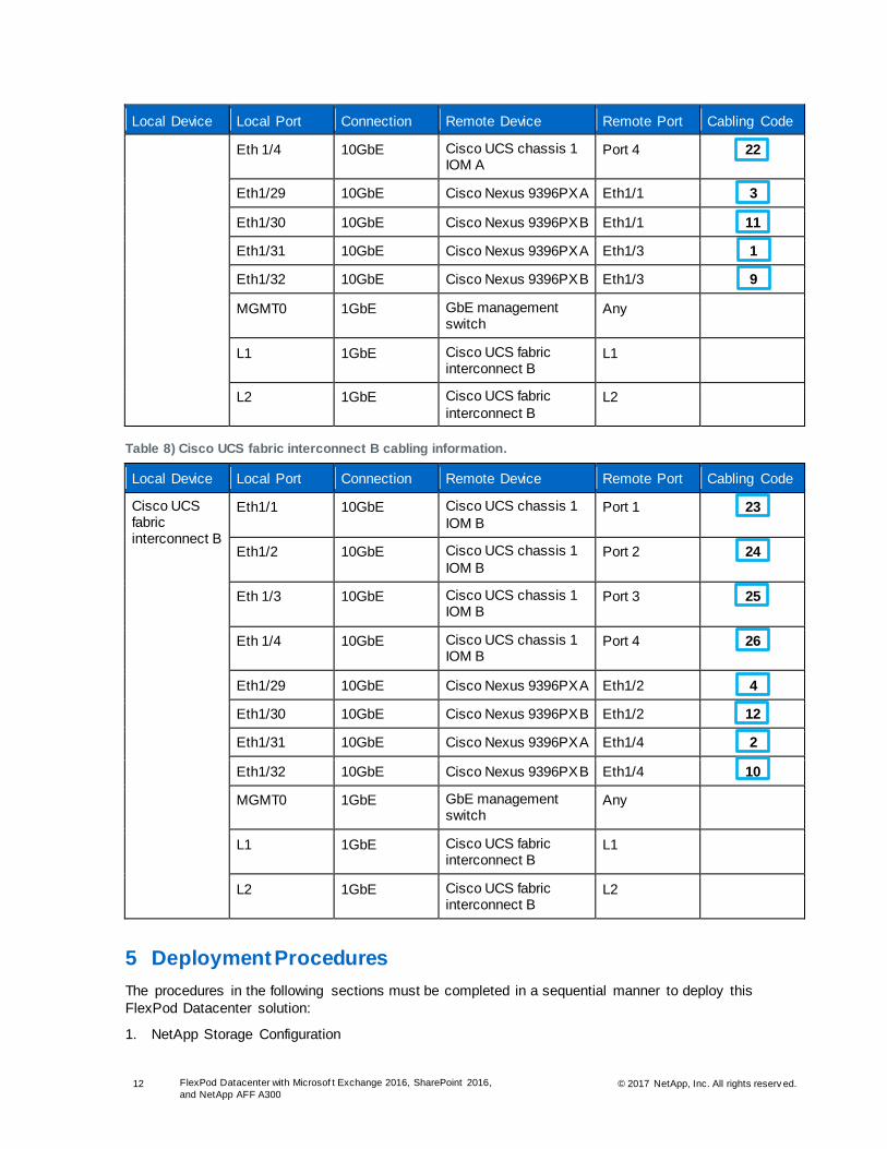
Table 7) Cisco UCS fabric interconnect A cabling information.
Local Device Local Port Connection Remote Device Remote Port Cabling Code
Cisco UCS fabric interconnect A
Eth1/1 10GbE Cisco UCS chassis 1 IOM A
Port 1 19
Eth1/2 10GbE Cisco UCS chassis 1 IOM A
Port 2 20
Eth 1/3 10GbE Cisco UCS chassis 1 IOM A
Port 3 21
12 FlexPod Datacenter with Microsof t Exchange 2016, SharePoint 2016,
and NetApp AFF A300 © 2017 NetApp, Inc. All rights reserv ed.
Local Device Local Port Connection Remote Device Remote Port Cabling Code
Eth 1/4 10GbE Cisco UCS chassis 1 IOM A
Port 4 22
Eth1/29 10GbE Cisco Nexus 9396PX A Eth1/1 3
Eth1/30 10GbE Cisco Nexus 9396PX B Eth1/1 11
Eth1/31 10GbE Cisco Nexus 9396PX A Eth1/3 1
Eth1/32 10GbE Cisco Nexus 9396PX B Eth1/3 9
MGMT0 1GbE GbE management switch
Any
L1 1GbE Cisco UCS fabric interconnect B
L1
L2 1GbE Cisco UCS fabric
interconnect B L2
Table 8) Cisco UCS fabric interconnect B cabling information.
Local Device Local Port Connection Remote Device Remote Port Cabling Code
Cisco UCS fabric interconnect B
Eth1/1 10GbE Cisco UCS chassis 1
IOM B Port 1 23
Eth1/2 10GbE Cisco UCS chassis 1
IOM B Port 2 24
Eth 1/3 10GbE Cisco UCS chassis 1 IOM B
Port 3 25
Eth 1/4 10GbE Cisco UCS chassis 1 IOM B
Port 4 26
Eth1/29 10GbE Cisco Nexus 9396PX A Eth1/2 4
Eth1/30 10GbE Cisco Nexus 9396PX B Eth1/2 12
Eth1/31 10GbE Cisco Nexus 9396PX A Eth1/4 2
Eth1/32 10GbE Cisco Nexus 9396PX B Eth1/4 10
MGMT0 1GbE GbE management switch
Any
L1 1GbE Cisco UCS fabric interconnect B
L1
L2 1GbE Cisco UCS fabric interconnect B
L2
5 Deployment Procedures
The procedures in the following sections must be completed in a sequential manner to deploy this
FlexPod Datacenter solution:
1. NetApp Storage Configuration

13 FlexPod Datacenter with Microsof t Exchange 2016, SharePoint 2016,
and NetApp AFF A300 © 2017 NetApp, Inc. All rights reserv ed.
2. Cisco UCS Server Configuration
3. Cisco Nexus Storage Networking Configuration
4. VMware vSphere Configuration
5. VMware vCenter 6.5a Configuration
6. NetApp Virtual Storage Console (VSC) 6.2.1 deployment
7. Service account creation
8. SQL Server 2016 Installation and Configuration
9. Microsoft SharePoint 2016 Installation and Configuration
10. DocAve 6 Installation
11. Microsoft Exchange 2016 Installation and Configuration
12. SnapManager for Exchange Installation and Configuration
5.1 NetApp Storage Configuration
AFF Series Controller
For instructions on the physical installation of AFF controllers, follow the procedures in the AFF Series
documentation on the NetApp Support site. When planning the physical location of the storage systems,
refer to the Hardware Universe.
NetApp Hardware Universe
The NetApp Hardware Universe is an online application that provides information about supported
hardware and software components for specific ONTAP versions. This tool provides configuration
information for all NetApp storage appliances that are currently supported by the ONTAP software. It can
also compare component compatibilities.
To verify configuration information in the Hardware Universe, complete the following steps:
1. Access the Hardware Universe site to verify that the hardware and software components are
supported with the version of ONTAP that you plan to install.
2. Click the Platforms tab to view the compatibility between ONTAP software versions and NetApp
storage appliances with the desired specifications.
3. Alternatively, click the Compare Storage Systems tab to compare components by storage appliance.
Disk Shelves
NetApp storage systems support a wide variety of disk shelves and disk drives. Visit the NetApp Support
site to view a complete list of supported disk shelves. This solution is built on DS224C disk shelves with
SSDs. These disks provide the highest level of performance available.
When using SAS disk shelves with NetApp storage controllers, refer to the SAS Disk Shelves Universal
SAS and ACP Cabling Guide for information about cabling guidelines.
Figure 4 illustrates the cabling diagram for this FlexPod use case on ONTAP.

14 FlexPod Datacenter with Microsof t Exchange 2016, SharePoint 2016,
and NetApp AFF A300 © 2017 NetApp, Inc. All rights reserv ed.
Figure 4) Cabling diagram for NetApp storage with NetApp disk shelves.
ONTAP
This procedure assumes that the storage system has been installed and cabled and is ready for setup.
For detailed information about storage system installation, see the preceding resources.
Configure ONTAP Nodes
Before running the setup script, review the configuration worksheets in the ONTAP 9.1 Software Setup
Guide to learn about the information required to configure ONTAP. Table 9 lists the information that you
need to configure two ONTAP nodes. You should customize the cluster detail values with the information
that is applicable to your deployment.
Table 9) Cluster details for the ONTAP software configuration.
Cluster Detail Cluster Detail Value
Cluster name <<var_clustername>>
ONTAP base license <<var_cluster_base_license_key>>
Cluster management IP address <<var_clustermgmt_ip>>
Cluster management netmask <<var_clustermgmt_mask>>
Cluster management port <<var_clustermgmt_port>>
Cluster management gateway <<var_clustermgmt_gateway>>
Cluster node 01 IP address <<var_node01_mgmt_ip>>

15 FlexPod Datacenter with Microsof t Exchange 2016, SharePoint 2016,
and NetApp AFF A300 © 2017 NetApp, Inc. All rights reserv ed.
Cluster Detail Cluster Detail Value
Cluster node 01 netmask <<var_node01_mgmt_mask>>
Cluster node 01 gateway <<var_node01_mgmt_gateway>>
Cluster node 01 service processor IP address <<var_node01_sp_ip>>
Cluster node 01 service processor netmask <<var_node01_sp_netmask>>
Cluster node 01 service processor gateway <<var_node01_sp_gateway>>
Cluster node 02 IP address <<var_node02_mgmt_ip>>
Cluster node 02 netmask <<var_node02_mgmt_mask>>
Cluster node 02 gateway <<var_node02_mgmt_gateway>>
Cluster node 02 service processor IP address <<var_node02_sp_ip>>
Cluster node 02 service processor netmask <<var_node02_sp_netmask>>
Cluster node 02 service processor gateway <<var_node02_sp_gateway>>
Cluster password <<var_password>>
Cluster DNS domain name <<var_dns_domain_name>>
Nameserver IP <<var_nameserver_ip>>
Controller location <<var_node_location>>
Cluster node 01 name <<var_node01>>
Cluster node 02 name <<var_node02>>
Cluster node 01 aggregate name <<var_node01_rootaggrname>>
Node Setup
Before you start the process of creating a storage cluster, you need to set up the individual nodes, which
involves enabling the NetApp AutoSupport® remote support diagnostics system, assigning the node
management IP addresses, and so on.
1. To perform the node setup, connect to the storage cluster node 01 console port. Console settings
are:
Baud rate: 115200
Data bits: 8
Parity: none
Stop bit: 1
Flow control: none
2. Enable AutoSupport on the node.
Welcome to node setup.
You can enter the following commands at any time:
"help" or "?" - if you want to have a question clarified,
"back" - if you want to change previously answered questions, and
"exit" or "quit" - if you want to quit the setup wizard.
Any changes you made before quitting will be saved.

16 FlexPod Datacenter with Microsof t Exchange 2016, SharePoint 2016,
and NetApp AFF A300 © 2017 NetApp, Inc. All rights reserv ed.
To accept a default or omit a question, do not enter a value.
This system will send event messages and weekly reports to NetApp Technical
Support.
To disable this feature, enter "autosupport modify -support disable" within 24
hours.
Enabling AutoSupport can significantly speed problem determination and
resolution should a problem occur on your system.
For further information on AutoSupport, see:
http://support.netapp.com/autosupport/
Type yes to confirm and continue {yes}: yes
3. Assign the node management IP address, netmask, and gateway.
Enter the node management interface port [e0M]: e0M
Enter the node management interface IP address: <<var_node01_mgmt_ip>>
Enter the node management interface netmask: <<var_node01_mgmt_mask>>
Enter the node management interface default gateway: <<var_node01_mgmt_gateway>>
4. After the node management IP is assigned, press Ctrl+C to get out of the cluster setup, log in to the
shell, and set the storage failover mode to HA.
login: admin
******************************************************
* This is a serial console session. Output from this *
* session is mirrored on the SP console session. *
******************************************************
::> storage failover modify -mode ha
Mode is already set to HA.
::> system node reboot
Warning: Are you sure you want to reboot node "localhost"? {y|n}: y
5. After the node reboots, set up the node with the preassigned values.
Welcome to node setup.
You can enter the following commands at any time:
"help" or "?" - if you want to have a question clarified,
"back" - if you want to change previously answered questions, and
"exit" or "quit" - if you want to quit the setup wizard.
Any changes you made before quitting will be saved.
To accept a default or omit a question, do not enter a value.
Enter the node management interface port [e0M]: Enter
Enter the node management interface IP address [10.61.184.218]: Enter
Enter the node management interface netmask [255.255.255.0]: Enter
Enter the node management interface default gateway [10.61.184.1]: Enter
This node has its management address assigned and is ready for cluster setup.
To complete cluster setup after all nodes are ready, download and run the System Setup utility
from the NetApp Support Site and use it to discover the configured nodes.
For System Setup, this node's management address is: 10.61.184.218.
Alternatively, you can use the "cluster setup" command to configure the cluster.
Wed Jul 13 13:10:49 UTC 2016
login:
6. Repeat this procedure for storage cluster node 02.

17 FlexPod Datacenter with Microsof t Exchange 2016, SharePoint 2016,
and NetApp AFF A300 © 2017 NetApp, Inc. All rights reserv ed.
Create Cluster on Node 01
In the ONTAP data management software, the first node in a cluster performs the cluster-create
operation. All other nodes perform a cluster-join operation. The first node in the cluster is considered
node 01. Use the values from Table 9 to complete the configuration of the cluster and each node.
To create a cluster on node 01, complete the following steps:
1. Keep using the console connection that you have connected to the storage cluster node 01.
2. At the login prompt, enter admin and run the following command:
login: admin
******************************************************
* This is a serial console session. Output from this *
* session is mirrored on the SP console session. *
******************************************************
::> cluster setup
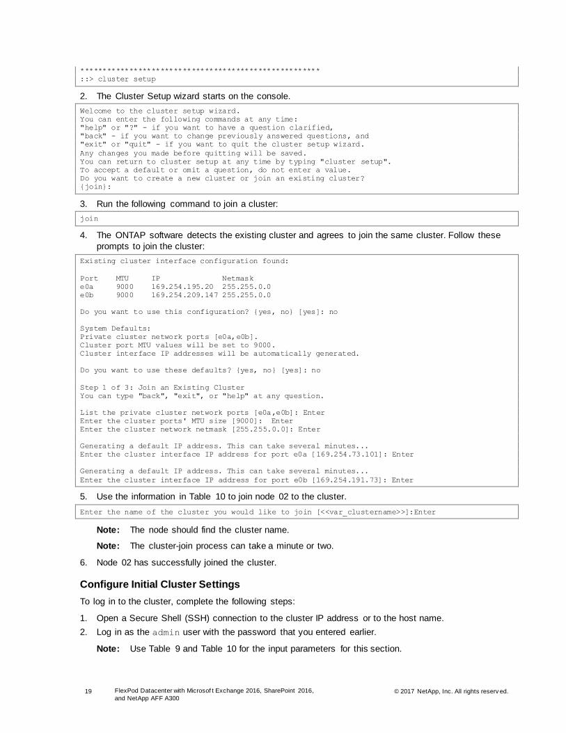
3. The Cluster Setup wizard starts on the console.
Welcome to the cluster setup wizard.
You can enter the following commands at any time:
"help" or "?" - if you want to have a question clarified,
"back" - if you want to change previously answered questions, and
"exit" or "quit" - if you want to quit the cluster setup wizard.
Any changes you made before quitting will be saved.
You can return to cluster setup at any time by typing "cluster setup".
To accept a default or omit a question, do not enter a value.
Do you want to create a new cluster or join an existing cluster? {create, join}:
4. Run the following command to create a new cluster:
create
5. Enter no for the single-node cluster option.
Do you intend for this node to be used as a single node cluster? {yes, no} [no]: no
6. Enter no for the option to use network switches for the cluster network.
Will the cluster network be configured to use network switches? [yes]:no
7. The system defaults are displayed. Enter no for the option to use the system defaults. Follow these
prompts to configure the cluster ports:
Existing cluster interface configuration found:
Port MTU IP Netmask
e0a 9000 169.254.122.114 255.255.0.0
e0b 9000 169.254.124.58 255.255.0.0
Do you want to use this configuration? {yes, no} [yes]:no
System Defaults:
Private cluster network ports [e0a,e0b].
Cluster port MTU values will be set to 9000.
Cluster interface IP addresses will be automatically generated.
Do you want to use these defaults? {yes, no} [yes]: no
Enter the cluster administrator's (username "admin") password: <<var_password>>
Retype the password: <<var_password>>
List the private cluster network ports [e0a,e0b]: Enter
Enter the cluster ports' MTU size [9000]: Enter
Enter the cluster network netmask [255.255.0.0]: Enter
Generating a default IP address. This can take several minutes...
Enter the cluster interface IP address for port e0a [169.254.28.157]: Enter

18 FlexPod Datacenter with Microsof t Exchange 2016, SharePoint 2016,
and NetApp AFF A300 © 2017 NetApp, Inc. All rights reserv ed.
Generating a default IP address. This can take several minutes...
Enter the cluster interface IP address for port e0b [169.254.32.222]: Enter
8. Use the information in Table 9 to create a cluster.
Enter the cluster name: <<var_clustername>>
Enter the cluster base license key: <<var_cluster_base_license_key>>
Creating cluster <<var_clustername>>
Enter an additional license key []:<<var_nfs_license>>
Enter an additional license key []:<<var_iscsi_license>>
Note: The cluster-create process can take a minute or two.
Note: For this design, we need to provide additional licenses for NetApp SnapRestore® data recovery software, NetApp FlexClone® data replication software, and the NetApp SnapManager suite.
Enter the cluster management interface port [e0c]: e0c
Enter the cluster management interface IP address: <<var_clustermgmt_ip>>
Enter the cluster management interface netmask: <<var_clustermgmt_mask>>
Enter the cluster management interface default gateway: <<var_clustermgmt_gateway>>
9. Enter the DNS domain name.
Enter the DNS domain names:<<var_dns_domain_name>>
Enter the name server IP addresses:<<var_nameserver_ip>>
Note: If you have more than one server IP address, separate them with commas.
10. The cluster-create operation is done. Follow the steps in the next subsection to join node 02 to the
cluster that we just created.
Join Node 02 to Cluster
The first node in the cluster performs the cluster-create operation. All other nodes perform a cluster-join
operation. The first node in the cluster is considered node 01, and the node joining the cluster in this
example is node 02. Table 10 lists the cluster network information required for joining node 02 to the
existing cluster. You should customize the cluster detail values with the information that is applicable to
your deployment.
Table 10) Cluster details for the cluster-join operation.
Cluster Details Cluster Detail Value
Cluster node 02 IP address <<var_node02_mgmt_ip>>
Cluster node 02 netmask <<var_node02_mgmt_mask>>
Cluster node 02 gateway <<var_node02_mgmt_gateway>>
Cluster node 02 service processor IP address <<var_node02_sp_ip>>
Cluster node 02 service processor netmask <<var_node02_sp_netmask>>
Cluster node 02 service processor gateway <<var_node02_sp_gateway>>
To join node 02 to the existing cluster, complete the following steps:
1. At the login prompt, enter admin and run the following command:
login: admin
******************************************************
* This is a serial console session. Output from this *
* session is mirrored on the SP console session. *
19 FlexPod Datacenter with Microsof t Exchange 2016, SharePoint 2016,
and NetApp AFF A300 © 2017 NetApp, Inc. All rights reserv ed.
******************************************************
::> cluster setup
2. The Cluster Setup wizard starts on the console.
Welcome to the cluster setup wizard.
You can enter the following commands at any time:
"help" or "?" - if you want to have a question clarified,
"back" - if you want to change previously answered questions, and
"exit" or "quit" - if you want to quit the cluster setup wizard.
Any changes you made before quitting will be saved.
You can return to cluster setup at any time by typing "cluster setup".
To accept a default or omit a question, do not enter a value.
Do you want to create a new cluster or join an existing cluster?
{join}:
3. Run the following command to join a cluster:
join
4. The ONTAP software detects the existing cluster and agrees to join the same cluster. Follow these
prompts to join the cluster:
Existing cluster interface configuration found:
Port MTU IP Netmask
e0a 9000 169.254.195.20 255.255.0.0
e0b 9000 169.254.209.147 255.255.0.0
Do you want to use this configuration? {yes, no} [yes]: no
System Defaults:
Private cluster network ports [e0a,e0b].
Cluster port MTU values will be set to 9000.
Cluster interface IP addresses will be automatically generated.
Do you want to use these defaults? {yes, no} [yes]: no
Step 1 of 3: Join an Existing Cluster
You can type "back", "exit", or "help" at any question.
List the private cluster network ports [e0a,e0b]: Enter
Enter the cluster ports' MTU size [9000]: Enter
Enter the cluster network netmask [255.255.0.0]: Enter
Generating a default IP address. This can take several minutes...
Enter the cluster interface IP address for port e0a [169.254.73.101]: Enter
Generating a default IP address. This can take several minutes...
Enter the cluster interface IP address for port e0b [169.254.191.73]: Enter
5. Use the information in Table 10 to join node 02 to the cluster.
Enter the name of the cluster you would like to join [<<var_clustername>>]:Enter
Note: The node should find the cluster name.
Note: The cluster-join process can take a minute or two.
6. Node 02 has successfully joined the cluster.
Configure Initial Cluster Settings
To log in to the cluster, complete the following steps:
1. Open a Secure Shell (SSH) connection to the cluster IP address or to the host name.
2. Log in as the admin user with the password that you entered earlier.
Note: Use Table 9 and Table 10 for the input parameters for this section.
20 FlexPod Datacenter with Microsof t Exchange 2016, SharePoint 2016,
and NetApp AFF A300 © 2017 NetApp, Inc. All rights reserv ed.
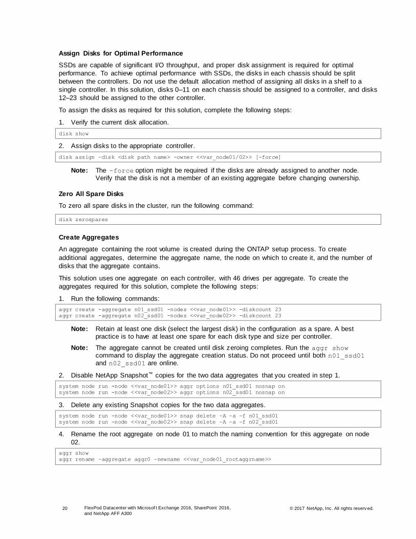
Assign Disks for Optimal Performance
SSDs are capable of significant I/O throughput, and proper disk assignment is required for optimal
performance. To achieve optimal performance with SSDs, the disks in each chassis should be split
between the controllers. Do not use the default allocation method of assigning all disks in a shelf to a
single controller. In this solution, disks 0–11 on each chassis should be assigned to a controller, and disks
12–23 should be assigned to the other controller.
To assign the disks as required for this solution, complete the following steps:
1. Verify the current disk allocation.
disk show
2. Assign disks to the appropriate controller.
disk assign –disk <disk path name> -owner <<var_node01/02>> [-force]
Note: The –force option might be required if the disks are already assigned to another node. Verify that the disk is not a member of an existing aggregate before changing ownership.
Zero All Spare Disks
To zero all spare disks in the cluster, run the following command:
disk zerospares
Create Aggregates
An aggregate containing the root volume is created during the ONTAP setup process. To create
additional aggregates, determine the aggregate name, the node on which to create it, and the number of
disks that the aggregate contains.
This solution uses one aggregate on each controller, with 46 drives per aggregate. To create the
aggregates required for this solution, complete the following steps:
1. Run the following commands:
aggr create -aggregate n01_ssd01 -nodes <<var_node01>> -diskcount 23
aggr create -aggregate n02_ssd01 -nodes <<var_node02>> -diskcount 23
Note: Retain at least one disk (select the largest disk) in the configuration as a spare. A best practice is to have at least one spare for each disk type and size per controller.
Note: The aggregate cannot be created until disk zeroing completes. Run the aggr show command to display the aggregate creation status. Do not proceed until both n01_ssd01 and n02_ssd01 are online.
2. Disable NetApp Snapshot™ copies for the two data aggregates that you created in step 1.
system node run -node <<var_node01>> aggr options n01_ssd01 nosnap on
system node run -node <<var_node02>> aggr options n02_ssd01 nosnap on
3. Delete any existing Snapshot copies for the two data aggregates.
system node run -node <<var_node01>> snap delete –A –a –f n01_ssd01
system node run -node <<var_node02>> snap delete –A –a –f n02_ssd01
4. Rename the root aggregate on node 01 to match the naming convention for this aggregate on node
02.
aggr show
aggr rename –aggregate aggr0 –newname <<var_node01_rootaggrname>>

21 FlexPod Datacenter with Microsof t Exchange 2016, SharePoint 2016,
and NetApp AFF A300 © 2017 NetApp, Inc. All rights reserv ed.
Verify Storage Failover
To confirm that storage failover is enabled, complete the following steps for a failover pair:
1. Verify the status of storage failover.
storage failover show
2. Both nodes, <<var_node01>> and <<var_node02>>, must be capable of performing a takeover. If
the nodes are capable of performing a takeover, go to step 4.
3. Enable failover on one of the two nodes.
storage failover modify -node <<var_node01>> -enabled true
Note: Enabling failover on one node enables it for both nodes.
4. Verify the HA status for the two-node cluster.
Note: This step is not applicable for clusters with more than two nodes.
cluster ha show
5. If HA is configured, go to step 7.
6. Enable the HA mode only for the two-node cluster.
Note: Do not run this command for clusters with more than two nodes because doing so causes problems with failover.
cluster ha modify -configured true
Do you want to continue? {y|n}: y
7. Verify that the hardware-assisted failover feature is correctly configured and, if needed, modify the
partner IP address.
storage failover hwassist show
storage failover modify –hwassist-partner-ip <<var_node02_mgmt_ip>> -node <<var_node01>>
storage failover modify –hwassist-partner-ip <<var_node01_mgmt_ip>> -node <<var_node02>>
Set Onboard UTA2 Ports Personality
To set the personality of the onboard unified target adapter 2 (UTA2) ports, complete the following steps:
1. Run the ucadmin show command to verify the current mode and current type of the ports.
Barsoom::> ucadmin show
Current Current Pending Pending Admin
Node Adapter Mode Type Mode Type Status
------------ ------- ------- --------- ------- --------- -----------
Barsoom-01 0e cna target - - online
Barsoom-01 0f cna target - - online
Barsoom-01 0g cna target - - online
Barsoom-01 0h cna target - - online
Barsoom-02 0e cna target - - online
Barsoom-02 0f cna target - - online
Barsoom-02 0g cna target - - online
Barsoom-02 0h cna target - - online
8 entries were displayed.
2. Verify that the current mode of the ports in use is cna and the current type is target. If this is not the
case, change the port personality by running the following command:
ucadmin modify -node <home node of the port> -adapter <port name> -mode cna -type target
Note: The ports must be offline in order to run this command:
network fcp adapter modify -node Colts-stcl-1-02 -adapter 0h -status-admin down

22 FlexPod Datacenter with Microsof t Exchange 2016, SharePoint 2016,
and NetApp AFF A300 © 2017 NetApp, Inc. All rights reserv ed.
Disable Flow Control on 10GbE and UTA2 Ports
A NetApp best practice is to disable flow control on all of the 10GbE and UTA2 ports that are connected
to external devices. To disable flow control, run the following command:
network port modify -node * -port e0e..e0h -flowcontrol-admin none
Warning: Changing the network port settings will cause a several second interruption in carrier.
Do you want to continue? {y|n}: y
Note: The –node and –port parameters in this example take advantage of the range operator available in the ONTAP shell.
Set Auto-Revert on Cluster Management Interface
To set the auto-revert parameter on the cluster management interface, run the following command:
network interface modify –vserver <<var_clustername>> -lif cluster_mgmt –auto-revert true
Set Up Management Broadcast Domain
To set up the default broadcast domain for the management network interfaces, run the following
commands:
broadcast-domain remove-ports -broadcast-domain Default -ports <<var_node01>>:e0e,
<<var_node01>>:e0f, <<var_node01>>:e0g, <<var_node01>>:e0h, <<var_node02>>:e0e,
<<var_node02>>:e0f, <<var_node02>>:e0g, <<var_node02>>:e0h
broadcast-domain show
Set Up Service Processor Network Interface
To assign a static IPv4 address to the service processor on each node, run the following commands:
system service-processor network modify -node <<var_node01>> -address-family IPv4 -enable true -
dhcp none -ip-address <<var_node01_sp_ip>> -netmask <<var_node01_sp_netmask>> -gateway
<<var_node01_sp_gateway>>
system service-processor network modify -node <<var_node02>> -address-family IPv4 -enable true -
dhcp none -ip-address <<var_node02_sp_ip>> -netmask <<var_node02_sp_netmask>> -gateway
<<var_node02_sp_gateway>>
Note: The service processor IP addresses should be in the same subnet as the node management IP addresses.
Create Jumbo Frame MTU Broadcast Domains in ONTAP
To create a data broadcast domain with an MTU of 9000, run the following commands:
broadcast-domain create -broadcast-domain Infra_NFS -mtu 9000
broadcast-domain create -broadcast-domain Infra_iSCSI-A -mtu 9000
broadcast-domain create -broadcast-domain Infra_iSCSI-B -mtu 9000
Create LACP Interface Groups
The LACP interface group (ifgrp) requires two or more Ethernet interfaces and a switch that supports the
Link Aggregation Control Protocol (LACP). Therefore, confirm that the switch is configured properly.
To create interface groups, run the following commands:
ifgrp create -node <<var_node01>> -ifgrp a0a -distr-func port -mode multimode_lacp
ifgrp add-port -node <<var_node01>> -ifgrp a0a -port e0e
ifgrp add-port -node <<var_node01>> -ifgrp a0a -port e0f
ifgrp add-port -node <<var_node01>> -ifgrp a0a -port e0g
ifgrp add-port -node <<var_node01>> -ifgrp a0a -port e0h

23 FlexPod Datacenter with Microsof t Exchange 2016, SharePoint 2016,
and NetApp AFF A300 © 2017 NetApp, Inc. All rights reserv ed.
ifgrp create -node <<var_node02>> -ifgrp a0a -distr-func port -mode multimode_lacp
ifgrp add-port -node <<var_node02>> -ifgrp a0a -port e0e
ifgrp add-port -node <<var_node02>> -ifgrp a0a -port e0f
ifgrp add-port -node <<var_node02>> -ifgrp a0a -port e0g
ifgrp add-port -node <<var_node02>> -ifgrp a0a -port e0h
ifgrp show
Note: All interfaces must be in the down status before being added to an interface group.
Note: The interface group name must follow the standard naming convention of <number><letter>, where:
<number> is an integer in the range of 0 to 999 without leading zeros.
<letter> is a lowercase letter.
Configure Jumbo Frames
To configure an ONTAP network port to use jumbo frames (which usually have an MTU of 9,000 bytes),
run the following command from the cluster shell:
network port modify -node * -port a0a -mtu 9000
WARNING: Changing the network port settings will cause a serveral second interruption in carrier.
Do you want to continue? {y|n}: y
Note: Modifications to an interface group cause the underlying physical ports to inherit the same configuration. If the ports are later removed from the interface group, they retain these same settings. However, the inverse is not true; modifying the individual ports does not modify the interface group of which the ports are a member.
Note: After the MTU for the interface group is set to 9,000, all new VLAN interfaces created on that interface group also have an MTU of 9,000 bytes. Existing VLAN interfaces retain their original MTU after the ifgroup is changed.
Create VLANs
To create NFS and iSCSI VLANs and add them to their respective broadcast domains, run the following
commands:
network port vlan create –node <<var_node01>> -vlan-name a0a-<<var_NFS_vlan_id>>
network port vlan create –node <<var_node02>> -vlan-name a0a-<<var_NFS_vlan_id>>
broadcast-domain add-ports -broadcast-domain <<var_NFS_broadcast_domain>> -ports
<<var_node01>>:a0a-<<var_NFS_vlan_id>>, <<var_node02>>:a0a-<<var_NFS_vlan_id>>
network port vlan create -node <<var_node01>> -vlan-name a0a-<<var_iSCSI-A_vlan_id>>
network port vlan create -node <<var_node01>> -vlan-name a0a-<<var_iSCSI-B_vlan_id>>
network port vlan create -node <<var_node02>> -vlan-name a0a-<<var_iSCSI-A_vlan_id>>
network port vlan create -node <<var_node02>> -vlan-name a0a-<<var_iSCSI-B_vlan_id>>
broadcast-domain add-ports -broadcast-domain <<var_iSCSI-A_broadcast_domain>> -ports
<<var_node01>>:a0a-<<var_iSCSI-A_vlan_id>>, <<var_node02>>:a0a-<<var_iSCSI-A_vlan_id>>
broadcast-domain add-ports -broadcast-domain <<var_iSCSI-B_broadcast_domain>> -ports
<<var_node01>>:a0a-<<var_iSCSI-B_vlan_id>>, <<var_node02>>:a0a-<<var_iSCSI-B_vlan_id>>
Enable Cisco Discovery Protocol
To enable the Cisco Discovery Protocol (CDP) on the NetApp storage controllers, run the following
command:
system node run -node * options cdpd.enable on
To be effective, CDP must also be enabled on directly connected networking equipment such as switches
and routers.
24 FlexPod Datacenter with Microsof t Exchange 2016, SharePoint 2016,
and NetApp AFF A300 © 2017 NetApp, Inc. All rights reserv ed.
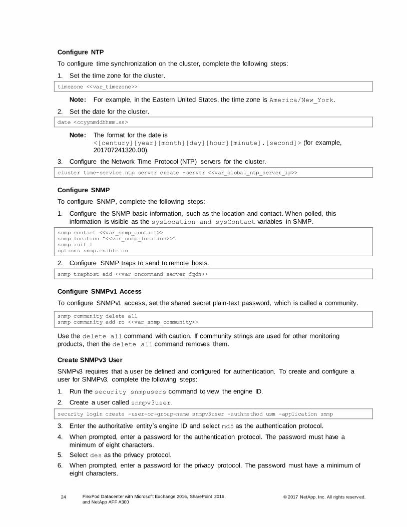
Configure NTP
To configure time synchronization on the cluster, complete the following steps:
1. Set the time zone for the cluster.
timezone <<var_timezone>>
Note: For example, in the Eastern United States, the time zone is America/New_York.
2. Set the date for the cluster.
date <ccyymmddhhmm.ss>
Note: The format for the date is <[century][year][month][day][hour][minute].[second]> (for example, 201707241320.00).
3. Configure the Network Time Protocol (NTP) servers for the cluster.
cluster time-service ntp server create -server <<var_global_ntp_server_ip>>
Configure SNMP
To configure SNMP, complete the following steps:
1. Configure the SNMP basic information, such as the location and contact. When polled, this
information is visible as the sysLocation and sysContact variables in SNMP.
snmp contact <<var_snmp_contact>>
snmp location “<<var_snmp_location>>”
snmp init 1
options snmp.enable on
2. Configure SNMP traps to send to remote hosts.
snmp traphost add <<var_oncommand_server_fqdn>>
Configure SNMPv1 Access
To configure SNMPv1 access, set the shared secret plain-text password, which is called a community.
snmp community delete all
snmp community add ro <<var_snmp_community>>
Use the delete all command with caution. If community strings are used for other monitoring
products, then the delete all command removes them.
Create SNMPv3 User
SNMPv3 requires that a user be defined and configured for authentication. To create and configure a
user for SNMPv3, complete the following steps:
1. Run the security snmpusers command to view the engine ID.
2. Create a user called snmpv3user.
security login create -user-or-group-name snmpv3user -authmethod usm -application snmp
3. Enter the authoritative entity ’s engine ID and select md5 as the authentication protocol.
4. When prompted, enter a password for the authentication protocol. The password must have a
minimum of eight characters.
5. Select des as the privacy protocol.
6. When prompted, enter a password for the privacy protocol. The password must have a minimum of
eight characters.

25 FlexPod Datacenter with Microsof t Exchange 2016, SharePoint 2016,
and NetApp AFF A300 © 2017 NetApp, Inc. All rights reserv ed.
Configure AutoSupport HTTPS
AutoSupport sends support summary information to NetApp through HTTPS. To configure AutoSupport,
run the following command:
system node autosupport modify -node * -state enable –mail-hosts <<var_mailhost>> -transport
https -support enable -to <<var_storage_admin_email>>
Note: To enable AutoSupport to send messages using SMTP, change the –transport value in the preceding command to smtp. When configuring AutoSupport to use SMTP, be sure to enable mail relay on the mail server for the cluster management and node management IP addresses.
Configure HTTPS Access
Secure access to the storage controller is configured by default with self-signed certificates.
Set Up Storage VM
Create Storage VM
To create an infrastructure storage virtual machine (SVM), complete the following steps:
Note: The SVM is referred to as a Vserver in the ONTAP command-line interface (CLI).
1. Run the vserver create command.
vserver create -vserver Infra-SVM -rootvolume rootvol -aggregate n01_ssd01 -rootvolume-security-
style unix
2. Select the SVM data protocols to configure.
vserver remove-protocols –vserver Infra-SVM -protocols fcp,cifs,ndmp
3. Add the two data aggregates to the infra-SVM aggregate list for the VSC.
vserver modify -vserver Infra-SVM -aggr-list n01_ssd01, n02_ssd01
4. Enable and run the NFS protocol in the infra-SVM.
nfs create -vserver Infra-SVM -udp disabled
5. Turn on the SVM vstorage parameter for the NetApp NFS VAAI plug-in.
vserver nfs modify –vserver Infra-SVM –vstorage enabled
vserver nfs show
Create Load-Sharing Mirror of SVM Root Volume
To create a load-sharing mirror of an SVM root volume, complete the following steps:
1. Create a volume to be the load-sharing mirror of the root volume of the infrastructure SVM on each
node.
volume create –vserver Infra-SVM –volume rootvol_m01 –aggregate n01_ssd01 –size 1GB –type DP
volume create –vserver Infra-SVM –volume rootvol_m02 –aggregate n02_ssd01 –size 1GB –type DP
2. Create a job schedule to update the root volume mirror relationships every 15 minutes.
job schedule interval create -name 15min -minutes 15
3. Create the mirroring relationships.
snapmirror create –source-path Infra-SVM:rootvol –destination-path Infra-SVM:rootvol_m01 –type LS
-schedule 15min
snapmirror create –source-path Infra-SVM:rootvol –destination-path Infra-SVM:rootvol_m02 –type LS
-schedule 15min

26 FlexPod Datacenter with Microsof t Exchange 2016, SharePoint 2016,
and NetApp AFF A300 © 2017 NetApp, Inc. All rights reserv ed.
4. Initialize the mirroring relationship.
snapmirror initialize-ls-set –source-path Infra-SVM:rootvol
Create iSCSI Service
Create the iSCSI service on each SVM.
Note: This command also starts the iSCSI service and sets the iSCSI IQN for the SVM.
iscsi create -vserver Infra-SVM
iscsi show
Configure HTTPS Access
Secure access to the storage controller is configured by default with self-signed certificates.
Configure NFSv3
To configure NFSv3 on the SVM, complete the following steps:
1. Create a new rule for each ESXi host in the default export policy. Assign a rule for each ESXi host created so that each host has its own rule index. For example, the first ESXi host has rule index 1,
the second ESXi host has rule index 2, and so on.
vserver export-policy rule create -vserver Infra-SVM -policyname default -ruleindex 1 -
clientmatch <<var_esxi_host1_nfs_ip>> -rorule sys -rwrule sys -superuser sys -allow-suid false
…
vserver export-policy rule create -vserver Infra-SVM -policyname default -ruleindex 8 -
clientmatch <<var_esxi_host8_nfs_ip>> -rorule sys -rwrule sys -superuser sys -allow-suid false
2. Assign the default export policy to the infrastructure SVM root volume.
volume modify -vserver Infra-SVM -volume rootvol -policy default
Create FlexVol Volumes
To create a NetApp FlexVol® volume, run the following commands:
volume create -vserver Infra-SVM -volume infra_datastore_1 -aggregate n01_ssd01 -size 1TB -state
online -policy default -junction-path /infra_datastore_1 -space-guarantee none -percent-snapshot-
space 0
volume create -vserver Infra-SVM -volume infra_swap -aggregate n02_ssd01 -size 100GB -state
online -policy default -junction-path /infra_swap -space-guarantee none -percent-snapshot-space 0
-snapshot-policy none
volume create -vserver Infra-SVM -volume esxi_boot -aggregate n02_ssd01 -size 500GB -state online
-policy default -space-guarantee none -percent-snapshot-space 0
snapmirror update-ls-set -source-path Infra-SVM:rootvol
Create Boot LUNs for ESXi Hosts
The following procedure describes the process for configuring boot LUNs on the SSD aggregates, but it
could be used on any ONTAP storage system. To create boot LUNs for ESXi hosts, complete the
following steps:
1. Turn off automatic Snapshot copies on the volume.
volume modify –vserver Infra-SVM –volume esxi_boot –snapshot-policy none
2. Enable deduplication on the volume.
volume efficiency on –vserver Infra-SVM –volume esxi_boot

27 FlexPod Datacenter with Microsof t Exchange 2016, SharePoint 2016,
and NetApp AFF A300 © 2017 NetApp, Inc. All rights reserv ed.
3. Create LUNs for ESXi boot partitions for infrastructure hosts.
lun create -vserver Infra-SVM -volume esxi_boot -lun VM-Host-Infra-01 -size 15GB -ostype vmware -
space-reserve disabled
…
lun create -vserver Infra-SVM -volume esxi_boot -lun VM-Host-Infra-08 -size 15GB -ostype vmware -
space-reserve disabled
Create iSCSI LIFs
To create four iSCSI LIFs (two on each node), run the following commands:
network interface create -vserver Infra-SVM -lif iscsi_lif01a -role data -data-protocol iscsi -
home-node <<var_node01>> -home-port a0a-<<var_iSCSI-A_vlan_id>> -address
<<var_node01_iscsi_lif01a_ip>> -netmask <<var_node01_iscsi_lif01a_mask>> -status-admin up -
failover-policy disabled -firewall-policy data -auto-revert false
network interface create -vserver Infra-SVM -lif iscsi_lif01b -role data -data-protocol iscsi -
home-node <<var_node01>> -home-port a0a-<<var_iSCSI-B_vlan_id>> -address
<<var_node01_iscsi_lif01b_ip>> -netmask <<var_node01_iscsi_lif01b_mask>> -status-admin up -
failover-policy disabled -firewall-policy data -auto-revert false
network interface create -vserver Infra-SVM -lif iscsi_lif02a -role data -data-protocol iscsi -
home-node <<var_node02>> -home-port a0a-<<var_iSCSI-A_vlan_id>> -address
<<var_node02_iscsi_lif02a_ip>> -netmask <<var_node02_iscsi_lif02a_mask>> -status-admin up -
failover-policy disabled -firewall-policy data -auto-revert false
network interface create -vserver Infra-SVM -lif iscsi_lif02b -role data -data-protocol iscsi -
home-node <<var_node02>> -home-port a0a-<<var_iSCSI-B_vlan_id>> -address
<<var_node02_iscsi_lif02b_ip>> -netmask <<var_node02_iscsi_lif02b_mask>> -status-admin up -
failover-policy disabled -firewall-policy data -auto-revert false
network interface show
Create NFS LIFs
To create an NFS LIF, run the following commands:
network interface create -vserver Infra-SVM -lif nfs_infra_node_1 -role data -data-protocol nfs -
home-node <<var_node01>> -home-port a0a-<<var_nfs_vlan_id>> -address <<var_node01_nfs_ip>> -
netmask <<var_node01_nfs_mask>> -status-admin up -failover-policy broadcast-domain-wide -
firewall-policy data -auto-revert true
network interface create -vserver Infra-SVM -lif nfs_infra_node_2 -role data -data-protocol nfs -
home-node <<var_node02>> -home-port a0a-<<var_nfs_vlan_id>> -address <<var_node02_nfs_ip>> -
netmask <<var_node02_nfs_mask>> -status-admin up -failover-policy broadcast-domain-wide -
firewall-policy data -auto-revert true
Add Infrastructure SVM Administrator
To add the infrastructure SVM administrator and SVM administration LIF in the out-of-band management
network, complete the following steps:
1. Run the following commands:
network interface create -vserver Infra-SVM -lif vsmgmt -role data -data-protocol none -home-node
<<var_node02>> -home-port e0M -address <<var_svm_mgmt_ip>> -netmask <<var_svm_mgmt_mask>> -
status-admin up -failover-policy broadcast-domain-wide -firewall-policy mgmt -auto-revert true
Note: The SVM management IP in this step should be in the same subnet as the storage cluster management IP.
2. Create a default route to allow the SVM management interface to reach the outside world.
network route create -vserver Infra-SVM -destination 0.0.0.0/0 -gateway <<var_svm_mgmt_gateway>>
network route show
3. Set a password for the SVM vsadmin user and unlock the user.

28 FlexPod Datacenter with Microsof t Exchange 2016, SharePoint 2016,
and NetApp AFF A300 © 2017 NetApp, Inc. All rights reserv ed.
security login password -username vsadmin -vserver Infra-SVM
Enter a new password: <<var_password>>
Enter it again: <<var_password>>
security login unlock -username vsadmin -vserver Infra-SVM
Configure iSCSI Boot
The iSCSI IQN values required for this step are not available until the Cisco UCS service profile has been
configured. Complete the steps in the section “Create Service Profile Templates” and then run the
following commands using the IQN variables listed in Table 12.
1. Create igroups for LUN mapping.
igroup create –vserver Infra-SVM –igroup VM-Host-Infra-01 –protocol iscsi –ostype vmware –
initiator <<var_vm_host_infra_01_iqn>>
igroup create –vserver Infra-SVM –igroup VM-Host-Infra-02 –protocol iscsi –ostype vmware –
initiator <<var_vm_host_infra_02_iqn>>
…
igroup create –vserver Infra-SVM –igroup VM-Host-Infra-08 –protocol iscsi –ostype vmware –
initiator <<var_vm_host_infra_08_iqn>>
2. Map boot LUNs to hosts.
lun map –vserver Infra-SVM –volume esxi_boot –lun VM-Host-Infra-01 –igroup VM-Host-Infra-01 –lun-
id 0
lun map –vserver Infra-SVM –volume esxi_boot –lun VM-Host-Infra-02 –igroup VM-Host-Infra-02 –lun-
id 0
…
lun map –vserver Infra-SVM –volume esxi_boot –lun VM-Host-Infra-08 –igroup VM-Host-Infra-08 –lun-
id 0
Set Up SVM for Exchange and SharePoint Workload
Create SVM
To create an SVM for Exchange and SharePoint, complete the following steps:
Note: The SVM is referred to as a Vserver in the ONTAP CLI.
1. Run the vserver create command.
vserver create -vserver Work-SVM -rootvolume rootvol -aggregate n02_ssd01 -rootvolume-security-
style unix
2. Select the SVM data protocols to configure.
vserver remove-protocols –vserver Work-SVM -protocols fcp,cifs,ndmp
3. Add the two data aggregates to the Work-SVM aggregate list for the VSC.
vserver modify -vserver Work-SVM -aggr-list n01_ssd01, n02_ssd01
4. Enable and run the NFS protocol in the Work-SVM.
nfs create -vserver Work-SVM -udp disabled
5. Turn on the SVM vstorage parameter for the NetApp NFS VAAI plug-in.
vserver nfs modify –vserver Work-SVM –vstorage enabled
vserver nfs show
Create Load-Sharing Mirror of SVM Root Volume
To create a load-sharing mirror of an SVM root volume, complete the following steps:
1. Create a volume to be the load-sharing mirror of the root volume of the infrastructure SVM on each
node.

29 FlexPod Datacenter with Microsof t Exchange 2016, SharePoint 2016,
and NetApp AFF A300 © 2017 NetApp, Inc. All rights reserv ed.
volume create –vserver Work-SVM –volume rootvol_m01 –aggregate n01_ssd01 –size 1GB –type DP
volume create –vserver Work-SVM –volume rootvol_m02 –aggregate n02_ssd01 –size 1GB –type DP
2. Create the mirroring relationships.
snapmirror create –source-path Work-SVM:rootvol –destination-path Work-SVM:rootvol_m01 –type LS -
schedule 15min
snapmirror create –source-path Work-SVM:rootvol –destination-path Work-SVM:rootvol_m02 –type LS -
schedule 15min
3. Initialize the mirroring relationship.
snapmirror initialize-ls-set –source-path Work-SVM:rootvol
Create iSCSI Service
Create the iSCSI service on each SVM. This command also starts the iSCSI service and sets the iSCSI
IQN for the SVM.
iscsi create -vserver Work-SVM
iscsi show
Configure HTTPS Access
Secure access to the storage controller is configured by default with self-signed certificates.
Configure NFSv3
To configure NFSv3 on the SVM, complete the following steps:
1. Create a new rule for each ESXi host in the default export policy. Ass ign a rule for each ESXi host
created so that each host has its own rule index. For example, the first ESXi host has rule index 1,
the second ESXi host has rule index 2, and so on.
vserver export-policy rule create -vserver Work-SVM -policyname default -ruleindex 9 -clientmatch
<<var_esxi_host1_nfs_ip>> -rorule sys -rwrule sys -superuser sys -allow-suid false
…
vserver export-policy rule create -vserver Work-SVM -policyname default -ruleindex 16 -
clientmatch <<var_esxi_host8_nfs_ip>> -rorule sys -rwrule sys -superuser sys -allow-suid false
2. Assign the default export policy to the infrastructure SVM root volume.
volume modify -vserver Work-SVM -volume rootvol -policy default
Create FlexVol Volumes
To create NetApp FlexVol volumes for SQL databases and SharePoint VMs, run the following
commands:
volume create -vserver Work-SVM -volume VM_datastore_1 -aggregate n01_ssd01 -size 1TB -state
online -policy default -junction-path /VM_datastore_1 -space-guarantee none -percent-snapshot-
space 0
volume create -vserver Work-SVM -volume SQL1_Data -aggregate n01_ssd01 -size 1TB -state online -
policy default -space-guarantee none -percent-snapshot-space 0
volume create -vserver Work-SVM -volume SQL1_SharePoint -aggregate n01_ssd01 -size 8TB -state
online -policy default -space-guarantee none -percent-snapshot-space 0
volume create -vserver Work-SVM -volume SQL1_Log -aggregate n01_ssd01 -size 2TB -state online -
policy default -space-guarantee none -percent-snapshot-space 0
volume create -vserver Work-SVM -volume SQL1_Snapinfo -aggregate n01_ssd01 -size 2TB -state
online -policy default -space-guarantee none -percent-snapshot-space 0
volume create -vserver Work-SVM -volume SQL2_Data -aggregate n02_ssd01 -size 1TB -state online -
policy default -space-guarantee none -percent-snapshot-space 0

30 FlexPod Datacenter with Microsof t Exchange 2016, SharePoint 2016,
and NetApp AFF A300 © 2017 NetApp, Inc. All rights reserv ed.
volume create -vserver Work-SVM -volume SQL2_SharePoint -aggregate n02_ssd01 -size 8TB -state
online -policy default -space-guarantee none -percent-snapshot-space 0
volume create -vserver Work-SVM -volume SQL2_Log -aggregate n02_ssd01 -size 2TB -state online -
policy default -space-guarantee none -percent-snapshot-space 0
volume create -vserver Work-SVM -volume SQL2_Snapinfo -aggregate n02_ssd01 -size 2TB -state
online -policy default -space-guarantee none -percent-snapshot-space 0
volume create -vserver Work-SVM -volume DocAve1_Media -aggregate n01_ssd01 -size 1.2TB -state
online -policy default -space-guarantee none -percent-snapshot-space 0
snapmirror update-ls-set -source-path Work-SVM:rootvol
Note: The Exchange volumes are created later due to their number and specificity.
Create iSCSI LIFs
To create four iSCSI LIFs (two on each node), run the following commands:
network interface create -vserver Work-SVM -lif iscsi_lif01a -role data -data-protocol iscsi -
home-node <<var_node01>> -home-port a0a-<<var_iSCSI-A_vlan_id>> -address
<<var_node01_iscsi_lif01a_ip>> -netmask <<var_node01_iscsi_lif01a_mask>> -status-admin up -
failover-policy disabled -firewall-policy data -auto-revert false
network interface create -vserver Work-SVM -lif iscsi_lif01b -role data -data-protocol iscsi -
home-node <<var_node01>> -home-port a0a-<<var_iSCSI-B_vlan_id>> -address
<<var_node01_iscsi_lif01b_ip>> -netmask <<var_node01_iscsi_lif01b_mask>> -status-admin up -
failover-policy disabled -firewall-policy data -auto-revert false
network interface create -vserver Work-SVM -lif iscsi_lif02a -role data -data-protocol iscsi -
home-node <<var_node02>> -home-port a0a-<<var_iSCSI-A_vlan_id>> -address
<<var_node02_iscsi_lif02a_ip>> -netmask <<var_node02_iscsi_lif02a_mask>> -status-admin up -
failover-policy disabled -firewall-policy data -auto-revert false
network interface create -vserver Work-SVM -lif iscsi_lif02b -role data -data-protocol iscsi -
home-node <<var_node02>> -home-port a0a-<<var_iSCSI-B_vlan_id>> -address
<<var_node02_iscsi_lif02b_ip>> -netmask <<var_node02_iscsi_lif02b_mask>> -status-admin up -
failover-policy disabled -firewall-policy data -auto-revert false
network interface show
Create NFS LIFs
To create an NFS LIF, run the following commands:
network interface create -vserver Work-SVM -lif nfs_work_node_1 -role data -data-protocol nfs -
home-node <<var_node01>> -home-port a0a-<<var_nfs_vlan_id>> -address <<var_nfs_work_1>> -netmask
<<var_nfs_work_1_mask>> -status-admin up -failover-policy broadcast-domain-wide -firewall-policy
data -auto-revert true
network interface create -vserver Work-SVM -lif nfs_work_node_2 -role data -data-protocol nfs -
home-node <<var_node02>> -home-port a0a-<<var_nfs_vlan_id>> -address <<var_nfs_work_2>> -netmask
<<var_nfs_work_2_mask>> -status-admin up -failover-policy broadcast-domain-wide -firewall-policy
data -auto-revert true
Add Infrastructure SVM Administrator
To add the work SVM administrator and SVM administration LIF in the out-of-band management network,
complete the following steps:
1. Run the following commands:
network interface create -vserver Work-SVM -lif vsmgmt -role data -data-protocol none -home-node
<<var_node02>> -home-port e0M -address <<var_svm_mgmt_ip>> -netmask <<var_svm_mgmt_mask>> -
status-admin up -failover-policy broadcast-domain-wide -firewall-policy mgmt -auto-revert true

31 FlexPod Datacenter with Microsof t Exchange 2016, SharePoint 2016,
and NetApp AFF A300 © 2017 NetApp, Inc. All rights reserv ed.
Note: The SVM management IP in this step should be in the same subnet as the storage cluster management IP.
2. Create a default route to allow the SVM management interface to reach the outside world.
network route create -vserver Work-SVM -destination 0.0.0.0/0 -gateway <<var_svm_mgmt_gateway>>
network route show
3. Set a password for the SVM vsadmin user and unlock the user.
security login password -username vsadmin -vserver Work-SVM
Enter a new password: <<var_password>>
Enter it again: <<var_password>>
security login unlock -username vsadmin -vserver Work-SVM
5.2 Cisco UCS Server Configuration
This section provides the complete configuration of the Cisco UCS server environment.
FlexPod Cisco UCS Base
Set Up Cisco UCS 6248 Fabric Interconnect for FlexPod Environments
This section provides detailed procedures for configuring the Cisco UCS for use in a FlexPod
environment. The steps explain how to provision the Cisco UCS B-Series servers and should be followed
precisely to avoid improper configuration.
Cisco UCS 6248 Fabric Interconnect A
To configure Cisco UCS for use in a FlexPod environment, complete the following steps:
1. Connect to the console port on the first Cisco UCS 6248 fabric interconnect.
Enter the configuration method. (console/gui) ? console
Enter the setup mode; setup newly or restore from backup.(setup/restore)? setup
You have chosen to setup a new Fabric interconnect. Continue? (y/n): y
Enforce strong password? (y/n) [y]: y
Enter the password for "admin": <<var_password>>
Confirm the password for "admin": <<var_password>>
Is this fabric interconnect part of a cluster (select 'no' for standalone)? (yes/no) [n]: y
Enter the switch fabric (A/B) []:A
Enter the system name: <<var_ucs_clustername>>
Physical switch Mgmt0 IPv4 address: <<var_ucsa_mgmt_ip>>
Physical switch Mgmt0 IPv4 netmask: <<var_ucsa_mgmt_mask>>
IPv4 address of the default gateway: <<var_ucsa_mgmt_gateway>>
Cluster IPv4 address: <<var_ucs_cluster_ip>>
Configure the DNS Server IPv4 address? (yes/no) [n]: y
DNS IPv4 address: <<var_nameserver_ip>>
Configure the default domain name? (yes/no) [n]: y
Default domain name: <<var_dns_domain_name>>
Join centralized management environment (UCS Central)? (yes/no) [n]: Enter
2. Review the settings displayed on the console. If they are correct, answer yes to apply and save the
configuration.
3. Wait for the login prompt to verify that the configuration has been saved.
Cisco UCS 6248 Fabric Interconnect B
To configure Cisco UCS for use in a FlexPod environment, complete the following steps:
1. Connect to the console port on the second Cisco UCS 6248 fabric interconnect.
Enter the configuration method. (console/gui) ? console
Installer has detected the presence of a peer Fabric interconnect. This Fabric interconnect will
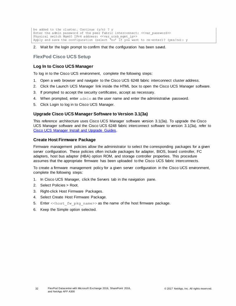
32 FlexPod Datacenter with Microsof t Exchange 2016, SharePoint 2016,
and NetApp AFF A300 © 2017 NetApp, Inc. All rights reserv ed.
be added to the cluster. Continue (y/n) ? y
Enter the admin password of the peer Fabric interconnect: <<var_password>>
Physical switch Mgmt0 IPv4 address: <<var_ucsb_mgmt_ip>>
Apply and save the configuration (select ‘no’ if you want to re-enter)? (yes/no): y
2. Wait for the login prompt to confirm that the configuration has been saved.
FlexPod Cisco UCS Setup
Log In to Cisco UCS Manager
To log in to the Cisco UCS environment, complete the following steps:
1. Open a web browser and navigate to the Cisco UCS 6248 fabric interconnect cluster address.
2. Click the Launch UCS Manager link inside the HTML box to open the Cisco UCS Manager software.
3. If prompted to accept the security certificates, accept as necessary.
4. When prompted, enter admin as the user name and enter the administrative password.
5. Click Login to log in to Cisco UCS Manager.
Upgrade Cisco UCS Manager Software to Version 3.1(3a)
This reference architecture uses Cisco UCS Manager software version 3.1(3a). To upgrade the Cisco
UCS Manager software and the Cisco UCS 6248 fabric interconnect software to version 3.1(3a), refer to
Cisco UCS Manager Install and Upgrade Guides.
Create Host Firmware Package
Firmware management policies allow the administrator to select the corresponding packages for a given
server configuration. These policies often include packages for adapter, BIOS, board controller, FC
adapters, host bus adapter (HBA) option ROM, and storage controller properties. This procedure
assumes that the appropriate firmware has been uploaded to the Cisco UCS fabric interconnects.
To create a firmware management policy for a given server configuration in the Cisco UCS environment,
complete the following steps:
1. In Cisco UCS Manager, click the Servers tab in the navigation pane.
2. Select Policies > Root.
3. Right-click Host Firmware Packages.
4. Select Create Host Firmware Package.
5. Enter <<host_fw_pkg_name>> as the name of the host firmware package.
6. Keep the Simple option selected.

33 FlexPod Datacenter with Microsof t Exchange 2016, SharePoint 2016,
and NetApp AFF A300 © 2017 NetApp, Inc. All rights reserv ed.
7. Select version 3.1(3a)B for the blade package.
8. Click OK to create the host firmware package.
9. Click OK.
Add Block of IP Addresses for Out-of-Band KVM Access
To create a block of IP addresses for server keyboard, video, and mouse (KVM) access in the Cisco UCS
environment, complete the following steps:
Note: This block of IP addresses should be in the same subnet as the management IP addresses for the Cisco UCS Manager. IP address blocks cannot be modified after they are created. If changes are required, the range of addresses must be deleted and then recreated.
1. In Cisco UCS Manager, click the LAN tab in the navigation pane.
2. Select Pools > Root > IP Pools.
3. Right-click IP Pools and select Create IP Pool.
4. Name the pool in-band-mgmt.
5. Click Next.
6. Click Add.
7. Enter the starting IP address of the block, the number of IP addresses required, and the subnet and
gateway information.

34 FlexPod Datacenter with Microsof t Exchange 2016, SharePoint 2016,
and NetApp AFF A300 © 2017 NetApp, Inc. All rights reserv ed.
8. Click Finish to create the IP block.
9. Click OK in the confirmation message.
Synchronize Cisco UCS to NTP
To synchronize the Cisco UCS environment to the NTP server, complete the following steps:
1. In the Cisco UCS Manager, click the Admin tab in the navigation pane.
2. Select All > Timezone Management.
3. In the Properties pane, select the appropriate time zone in the Timezone menu.
4. Click Save Changes and then click OK.
5. Click Add NTP Server.
6. Enter <<var_global_ntp_server_ip>> and click OK.
7. Click OK.
Edit Chassis Discovery Policy
Setting the discovery policy simplifies the addition of Cisco UCS B-Series chassis and Cisco UCS C-
Series servers.
To modify the chassis discovery policy, complete the following steps:
1. In Cisco UCS Manager, click the Equipment tab in the navigation pane and select Equipment from
the tree on the left.
2. In the right pane, click the Policies tab.

35 FlexPod Datacenter with Microsof t Exchange 2016, SharePoint 2016,
and NetApp AFF A300 © 2017 NetApp, Inc. All rights reserv ed.
3. Under Global Policies, set Chassis/FEX Discovery Policy to 4 Link or set it to match the number of
uplink ports that are cabled between the chassis and the fabric interconnects.
4. Set the Link Grouping Preference option to Port Channel.
5. Click Save Changes.
6. Click OK.
Enable Server and Uplink Ports
To enable server and uplink ports, complete the following steps:
1. In Cisco UCS Manager, click the Equipment tab in the navigation pane.
2. Select Equipment > Fabric Interconnects > Fabric Interconnect A (Primary) > Fixed Module.
3. Expand Ethernet Ports.
4. Select the ports that are connected to the chassis. Right-click the ports and select Configure as
Server Port.
5. Click Yes to confirm the server ports and click OK.
6. Select ports 29, 30, 31, and 32, which are connected to the Cisco Nexus 9396PX switches. Right-
click the ports and select Configure as Uplink Port.
7. Click Yes to confirm the uplink ports and click OK.
8. In the left pane, navigate to fabric interconnect A. In the right pane, navigate to Physical Ports >
Ethernet Ports. Confirm that the ports are configured correctly in the If Role column.
9. Select Equipment > Fabric Interconnects > Fabric Interconnect B (Subordinate) > Fixed Module.
10. Expand Ethernet Ports.
11. Select the ports that are connected to the chassis. Right-click the ports and select Configure as
Server Port.
12. Click Yes to confirm server ports and click OK.

36 FlexPod Datacenter with Microsof t Exchange 2016, SharePoint 2016,
and NetApp AFF A300 © 2017 NetApp, Inc. All rights reserv ed.
13. Select ports 29, 30, 31, and 32, which are connected to the Cisco Nexus 9396 switches. Right-click
the ports and select Configure as Uplink Port.
14. Click Yes to confirm the uplink ports and click OK.
15. In the left pane, navigate to fabric interconnect B. In the right pane, navigate to Physical Ports >
Ethernet Ports. Confirm that the ports are configured correctly in the If Role column.
Acknowledge Cisco UCS Chassis
To acknowledge all Cisco UCS chassis, complete the following steps:
1. In Cisco UCS Manager, click the Equipment tab in the Navigation pane.
2. Expand Chassis and select the chassis that is listed.
3. Right-click the chassis and select Acknowledge Chassis.
4. Click Yes and then click OK to complete chassis acknowledgement.
Create Uplink Port Channels to Cisco Nexus 9396PX Switches
To configure the necessary port channels in the Cisco UCS environment, complete the following steps:
1. In Cisco UCS Manager, click the LAN tab in the navigation pane.
Note: This procedure creates two port channels: one from fabric A to both Cisco Nexus 9396PX switches and one from fabric B to both Cisco Nexus 9396PX switches.
2. Under LAN > LAN Cloud, expand the fabric A node.
3. Right-click Port Channels.
4. Select Create Port Channel.
5. Enter <<var_fabric_A_Portchannel_ID>> as the unique ID of the port channel.
6. Enter <<var_fabric_A_Portchannel_name>> as the name of the port channel.
7. Click Next.
8. Select the following ports to be added to the port channel:
Slot ID 1 and port 29
Slot ID 1 and port 30

37 FlexPod Datacenter with Microsof t Exchange 2016, SharePoint 2016,
and NetApp AFF A300 © 2017 NetApp, Inc. All rights reserv ed.
Slot ID 1 and port 31
Slot ID 1 and port 32
9. Click >> to add the ports to the port channel.
10. Click Finish to create the port channel.
11. Click OK.
12. In the navigation pane, under LAN > LAN Cloud, expand the fabric B node.
13. Right-click Port Channels.
14. Select Create Port Channel.
15. Enter <<var_fabric_B_Portchannel_ID>> as the unique ID of the port channel.
16. Enter <<var_fabric_B_Portchannel_name>> as the name of the port channel.
17. Click Next.
18. Select the following ports to be added to the port channel:
Slot ID 1 and port 29
Slot ID 1 and port 30
Slot ID 1 and port 31
Slot ID 1 and port 32
19. Click >> to add the ports to the port channel.
20. Click Finish to create the port channel.
21. Click OK.
Create Organization (Optional)
Organizations are used to organize resources and restrict access to various groups within the IT
organization, thereby enabling multitenancy of the compute resources.
Note: Although the use of organizations is not assumed in this document, this section covers the process of creating an organization.
To configure an organization in the Cisco UCS environment, complete the following steps:
1. In Cisco UCS Manager, from the menu in the toolbar at the top of the window, select Create
Organization.

38 FlexPod Datacenter with Microsof t Exchange 2016, SharePoint 2016,
and NetApp AFF A300 © 2017 NetApp, Inc. All rights reserv ed.
2. Enter a name for the organization.
3. Optional: Enter a description for the organization.
4. Click OK.
5. Click OK in the confirmation message.
Create MAC Address Pools
To configure the necessary MAC address pools for the Cisco UCS environment, complete the following
steps:
1. In Cisco UCS Manager, click the LAN tab in the navigation pane.
2. Select Pools > Root.
Note: This procedure creates two MAC address pools, one for each switching fabric.
3. Right-click MAC Pools under the root organization.
4. Select Create MAC Pool to create the MAC address pool.
5. Enter MAC_Pool_A as the name of the MAC pool.
6. Optional: Enter a description for the MAC pool.
7. Keep the assignment order setting at Default.
8. Click Next.
9. Click Add to add a block of MAC addresses to the pool.
10. Specify the starting MAC address in the block for fabric A.
Note: For the FlexPod solution, the recommendation is to place 0A in the next-to-last octet of the starting MAC address to identify all MAC addresses in this pool as fabric A addresses.
11. Specify a size for the MAC address pool that is sufficient to support the available blade or server
resources.
12. Click OK.
13. Click Finish.
14. In the confirmation message, click OK.

39 FlexPod Datacenter with Microsof t Exchange 2016, SharePoint 2016,
and NetApp AFF A300 © 2017 NetApp, Inc. All rights reserv ed.
15. Right-click MAC Pools under the root organization.
16. Select Create MAC Pool to create the MAC address pool.
17. Enter MAC_Pool_B as the name of the MAC pool.
18. Optional: Enter a description for the MAC pool.
19. Keep the assignment order setting at Default.
20. Click Next.
21. Click Add to add a block of MAC addresses to the pool.
22. Specify the starting MAC address in the block for fabric B.
Note: For the FlexPod solution, the recommendation is to place 0B in the next-to-last octet of the starting MAC address to identify all MAC addresses in this pool as fabric B addresses.
23. Specify a size for the MAC address pool that is sufficient to support the available blade or server
resources.
24. Click OK.
25. Click Finish.
26. In the confirmation message, click OK.
Create IQN Pools for iSCSI Boot
To configure the necessary IQN pools for the Cisco UCS environment, complete the following steps:
1. In the Cisco UCS Manager, select the SAN tab on the left.
2. Select Pools > Root.
3. Right-click IQN Pools under the root organization.
4. Select Create IQN Suffix Pool to create the IQN pool.
5. Enter IQN_Pool for the name of the IQN pool.
6. Optional: Enter a description for the IQN pool.
7. Enter iqn.1992-08.com.cisco as the prefix.
8. Select Sequential for Assignment Order.
9. Click Next.
10. Click Add.
11. Enter ucs-host as the suffix.
12. Enter 1 in the From field.
13. Specify a size of the IQN block sufficient to support the available server resources.
14. Click OK.
40 FlexPod Datacenter with Microsof t Exchange 2016, SharePoint 2016,
and NetApp AFF A300 © 2017 NetApp, Inc. All rights reserv ed.
15. Click Finish.
16. In the message box that displays, click OK.
Create IP Pools for iSCSI Boot
These steps provide details for configuring the necessary IP pools iSCSI boot for the Cisco UCS
environment.
1. In the Cisco UCS Manager, select the LAN tab on the left.
2. Select Pools > Root.
3. Two IP pools are created, one for each switching fabric.
4. Right-click IP Pools under the root organization.
5. Select Create IP Pool to create the IP pool.
6. Enter iSCSI_IP_Pool_A for the name of the IP pool.
7. Optional: Enter a description of the IP pool.
8. Select Sequential for Assignment Order.
9. Click Next.
10. Click Add.
11. In the From field, enter the beginning of the range to assign as iSCSI IP addresses.
12. Set the size to enough addresses to accommodate the servers.
13. Click OK.
14. Click Finish.
15. Right-click IP Pools under the root organization.
16. Select Create IP Pool to create the IP pool.
17. Enter iSCSI_IP_Pool_B for the name of the IP pool.
18. Optional: Enter a description of the IP pool.
19. Select Sequential for Assignment Order.
20. Click Next.
21. Click Add.
22. In the From field, enter the beginning of the range to assign as iSCSI IP addresses.
23. Set the size to enough addresses to accommodate the servers.
24. Click OK.
25. Click Finish.
Create UUID Suffix Pool
To configure the necessary universally unique identifier (UUID) suffix pool for the Cisco UCS
environment, complete the following steps:
1. In Cisco UCS Manager, click the Servers tab in the navigation pane.
2. Select Pools > Root.
3. Right-click UUID Suffix Pools.
4. Select Create UUID Suffix Pool.
5. Enter UUID_Pool as the name of the UUID suffix pool.
6. Optional: Enter a description for the UUID suffix pool.
7. Keep the Prefix setting as Derived.

41 FlexPod Datacenter with Microsof t Exchange 2016, SharePoint 2016,
and NetApp AFF A300 © 2017 NetApp, Inc. All rights reserv ed.
8. Keep the Assignment Order setting at Default.
9. Click Next.
10. Click Add to add a block of UUIDs to the pool.
11. Keep the From field at the default setting.
12. Specify a size for the UUID block that is sufficient to support the available blade or server resources.
13. Click OK.
14. Click Finish.
15. Click OK.
Create Server Pool (Optional)
To configure the necessary server pools for the Cisco UCS environment, complete the following steps:
Note: Consider creating unique server pools to achieve the granularity that is required in your environment.
1. In Cisco UCS Manager, click the Servers tab in the navigation pane.
2. Select Pools > Root.
3. Right-click Server Pools.
4. Select Create Server Pool.
5. Enter Host_Pool as the name of the server pool.
6. Optional: Enter a description for the server pool.
7. Click Next.
8. Select the servers to be used for the pool and click >> to add them to the Host_Pool server pool.
9. Click Finish.
10. Click OK.
Create VLANs
To configure the necessary virtual local area networks (VLANs) for the Cisco UCS environment, complete
the following steps:
1. In Cisco UCS Manager, click the LAN tab in the navigation pane.
2. Select LAN > LAN Cloud.

42 FlexPod Datacenter with Microsof t Exchange 2016, SharePoint 2016,
and NetApp AFF A300 © 2017 NetApp, Inc. All rights reserv ed.
3. Right-click VLANs.
4. Select Create VLANs.
5. Enter Native-VLAN as the name of the VLAN to be used as the native VLAN.
6. Keep the Common/Global option selected for the scope of the VLAN.
7. Enter the native VLAN ID.
8. Keep the Sharing Type as None.
9. Click OK and then click OK again.
10. Expand the list of VLANs in the navigation pane, right-click the newly created Native VLAN, and
select Set as Native VLAN.
11. Click Yes and then click OK.
12. Right-click VLANs.
13. Select Create VLANs.
14. Enter iSCSI-A-VLAN as the name of the VLAN to be used for the first iSCSI VLAN.
15. Keep the Common/Global option selected for the scope of the VLAN.
16. Enter the VLAN ID for the first iSCSI VLAN.
17. Click OK and then OK again.
18. Right-click VLANs.
19. Select Create VLANs.
20. Enter iSCSI-B-VLAN as the name of the VLAN to be used for the second iSCSI VLAN.
21. Keep the Common/Global option selected for the scope of the VLAN.
22. Enter the VLAN ID for the second iSCSI VLAN.
23. Click OK and then OK again.
24. Right-click VLANs.
25. Select Create VLANs.
26. Enter Mgmt-VLAN as the name of the VLAN to be used for management traffic.
27. Keep the Common/Global option selected for the scope of the VLAN.
28. Enter the in-band management VLAN ID.
29. Keep the Sharing Type as None.
30. Click OK and then click OK again.
31. Right-click VLANs.
32. Select Create VLANs.
33. Enter NFS-VLAN as the name of the VLAN to be used for NFS.
34. Keep the Common/Global option selected for the scope of the VLAN.
35. Enter the NFS VLAN ID.
36. Keep the Sharing Type as None.
37. Click OK and then click OK again.
38. Right-click VLANs.
39. Select Create VLANs.
40. Enter vMotion as the name of the VLAN to be used for vMotion.
41. Keep the Common/Global option selected for the scope of the VLAN.
42. Enter the vMotion VLAN ID.
43. Keep the Sharing Type as None.
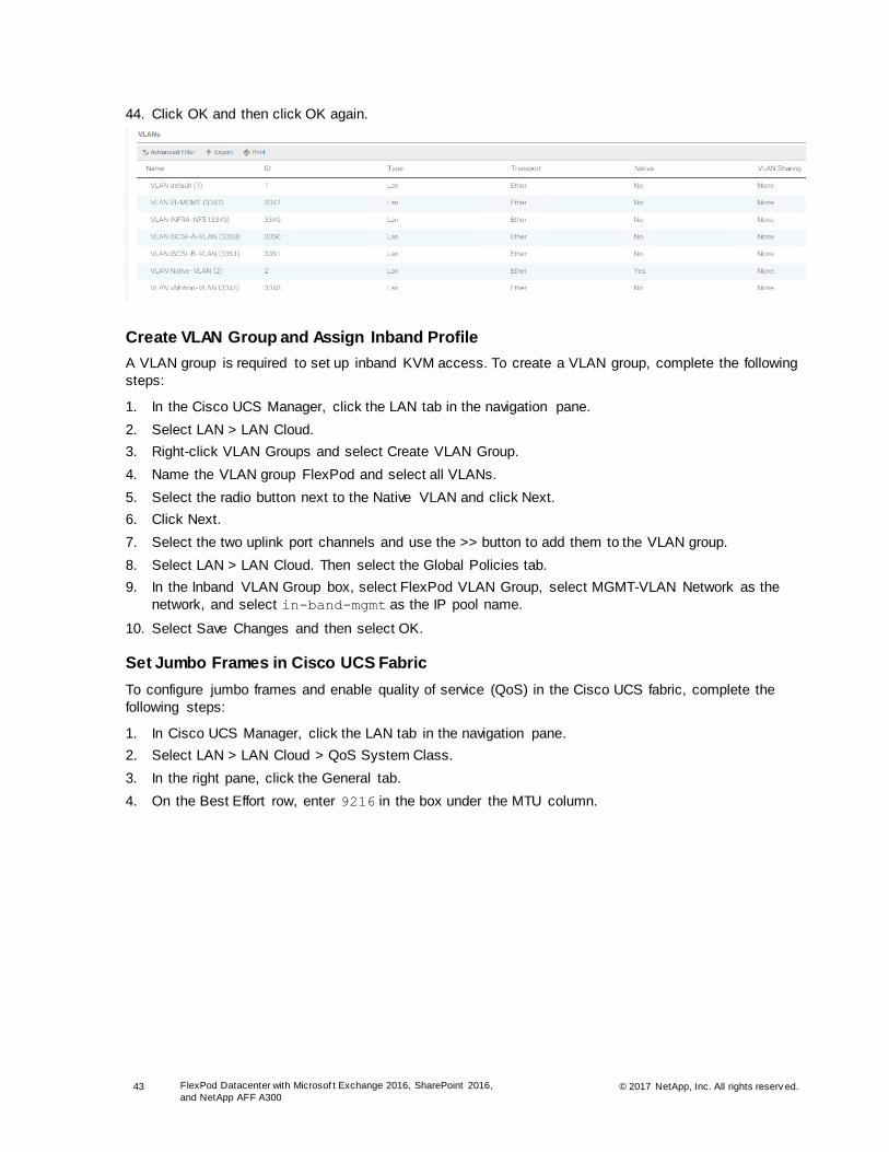
43 FlexPod Datacenter with Microsof t Exchange 2016, SharePoint 2016,
and NetApp AFF A300 © 2017 NetApp, Inc. All rights reserv ed.
44. Click OK and then click OK again.
Create VLAN Group and Assign Inband Profile
A VLAN group is required to set up inband KVM access. To create a VLAN group, complete the following
steps:
1. In the Cisco UCS Manager, click the LAN tab in the navigation pane.
2. Select LAN > LAN Cloud.
3. Right-click VLAN Groups and select Create VLAN Group.
4. Name the VLAN group FlexPod and select all VLANs.
5. Select the radio button next to the Native VLAN and click Next.
6. Click Next.
7. Select the two uplink port channels and use the >> button to add them to the VLAN group.
8. Select LAN > LAN Cloud. Then select the Global Policies tab.
9. In the Inband VLAN Group box, select FlexPod VLAN Group, select MGMT-VLAN Network as the
network, and select in-band-mgmt as the IP pool name.
10. Select Save Changes and then select OK.
Set Jumbo Frames in Cisco UCS Fabric
To configure jumbo frames and enable quality of service (QoS) in the Cisco UCS fabric, complete the
following steps:
1. In Cisco UCS Manager, click the LAN tab in the navigation pane.
2. Select LAN > LAN Cloud > QoS System Class.
3. In the right pane, click the General tab.
4. On the Best Effort row, enter 9216 in the box under the MTU column.
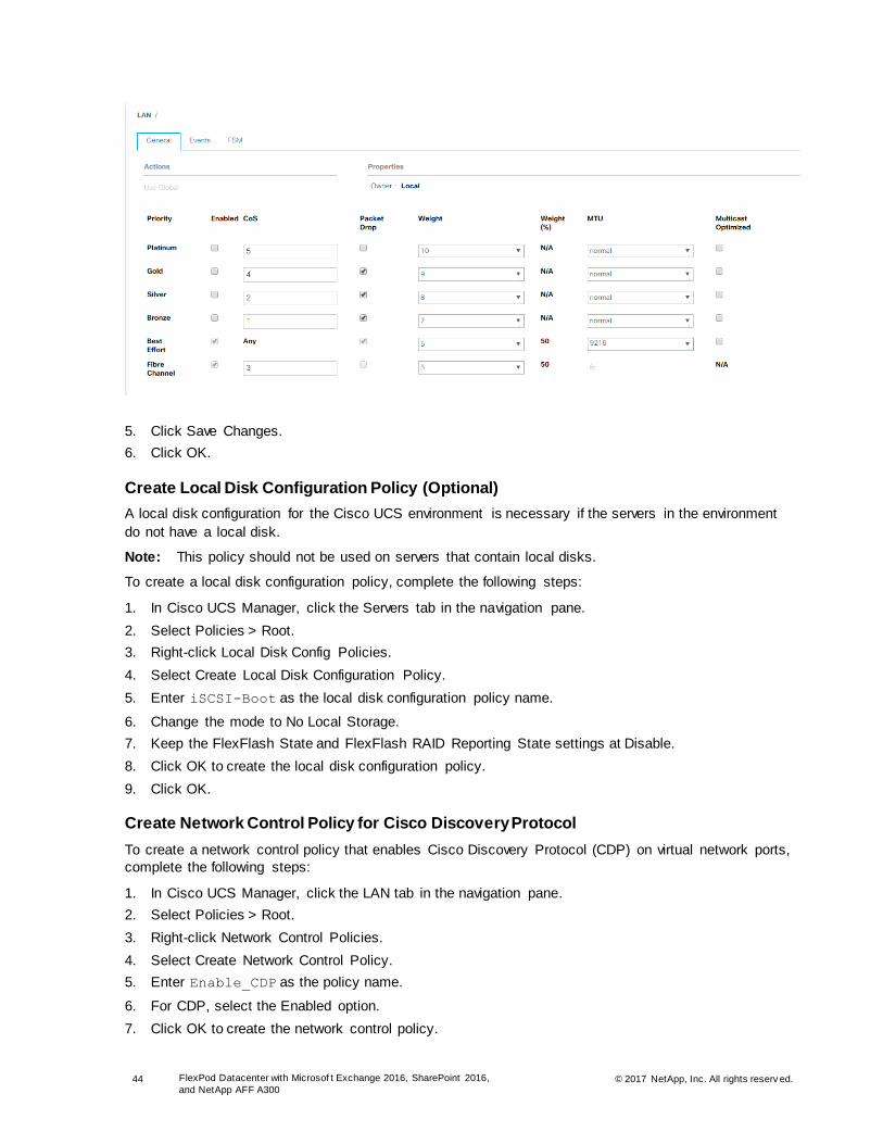
44 FlexPod Datacenter with Microsof t Exchange 2016, SharePoint 2016,
and NetApp AFF A300 © 2017 NetApp, Inc. All rights reserv ed.
5. Click Save Changes.
6. Click OK.
Create Local Disk Configuration Policy (Optional)
A local disk configuration for the Cisco UCS environment is necessary if the servers in the environment
do not have a local disk.
Note: This policy should not be used on servers that contain local disks.
To create a local disk configuration policy, complete the following steps:
1. In Cisco UCS Manager, click the Servers tab in the navigation pane.
2. Select Policies > Root.
3. Right-click Local Disk Config Policies.
4. Select Create Local Disk Configuration Policy.
5. Enter iSCSI-Boot as the local disk configuration policy name.
6. Change the mode to No Local Storage.
7. Keep the FlexFlash State and FlexFlash RAID Reporting State settings at Disable.
8. Click OK to create the local disk configuration policy.
9. Click OK.
Create Network Control Policy for Cisco Discovery Protocol
To create a network control policy that enables Cisco Discovery Protocol (CDP) on virtual network ports,
complete the following steps:
1. In Cisco UCS Manager, click the LAN tab in the navigation pane.
2. Select Policies > Root.
3. Right-click Network Control Policies.
4. Select Create Network Control Policy.
5. Enter Enable_CDP as the policy name.
6. For CDP, select the Enabled option.
7. Click OK to create the network control policy.

45 FlexPod Datacenter with Microsof t Exchange 2016, SharePoint 2016,
and NetApp AFF A300 © 2017 NetApp, Inc. All rights reserv ed.
8. Click OK.
Create Power Control Policy
To create a power control policy for the Cisco UCS environment, complete the following steps:
1. In Cisco UCS Manager, click the Servers tab in the navigation pane.
2. Select Policies > Root.
3. Right-click Power Control Policies.
4. Select Create Power Control Policy.
5. Enter No-Power-Cap as the power control policy name.
6. Change the power capping setting to No Cap.
7. Click OK to create the power control policy.
8. Click OK.
Create vNIC/vHBA Placement Policy for VM Infrastructure Hosts
To create a virtual network interface card/virtual host bus adapter (vNIC/vHBA) placement policy for the
infrastructure hosts, complete the following steps:
1. In Cisco UCS Manager, click the Servers tab in the navigation pane.
2. Select Policies > Root.
3. Right-click vNIC/vHBA Placement Policies.
4. Select Create Placement Policy.

46 FlexPod Datacenter with Microsof t Exchange 2016, SharePoint 2016,
and NetApp AFF A300 © 2017 NetApp, Inc. All rights reserv ed.
5. Enter Colts-Host as the name of the placement policy.
6. Click 1 and select Assigned Only under the Selection Preference column.
7. Click OK and then click OK again.
Update Default Maintenance Policy
To update the default maintenance policy, complete the following steps:
1. In Cisco UCS Manager, click the Servers tab in the navigation pane.
2. Select Policies > Root.
3. Select Maintenance Policies > Default.
4. Change the reboot policy setting to User Ack.
5. Click Save Changes.
6. Click OK to acknowledge the change.
Create vNIC Templates
This section describes how to create the required vNICs.

47 FlexPod Datacenter with Microsof t Exchange 2016, SharePoint 2016,
and NetApp AFF A300 © 2017 NetApp, Inc. All rights reserv ed.
Create Data vNICs
To create multiple vNIC templates for the Cisco UCS environment, complete the following steps:
1. In Cisco UCS Manager, click the LAN tab in the navigation pane.
2. Select Policies > Root.
3. Right-click vNIC Templates.
4. Select Create vNIC Template.
5. Enter vNIC_Template_A as the vNIC template name.
6. For fabric ID, select Fabric A.
Note: Do not select the Enable Failover checkbox.
Note: Under Target, do not select the VM checkbox.
7. Select Updating Template as the template type.
8. Under VLANs, select the checkboxes for the following VLANs:
MGMT-VLAN
Native-VLAN
vMotion-VLAN
NFS-VLAN
9. Set Native-VLAN as the native VLAN.
10. For MTU, enter 9000.
11. In the MAC Pool list, select MAC_Pool_A.
12. In the Network Control Policy list, select Enable_CDP.
13. Click OK to create the vNIC template.
14. Click OK.
15. In the navigation pane, click the LAN tab.

48 FlexPod Datacenter with Microsof t Exchange 2016, SharePoint 2016,
and NetApp AFF A300 © 2017 NetApp, Inc. All rights reserv ed.
16. Select Policies > Root.
17. Right-click vNIC Templates.
18. Select Create vNIC Template.
19. Enter vNIC_Template_B as the vNIC template name.
20. Select Fabric B.
Note: Do not select the Enable Failover checkbox.
Note: Under Target, do not select the VM checkbox.
21. Select Updating Template as the template type.
22. Under VLANs, select the checkboxes for the following VLANs:
MGMT-VLAN
Native-VLAN
vMotion-VLAN
NFS-VLAN
23. Set Native-VLAN as the native VLAN.
24. For MTU, enter 9000.
25. In the MAC Pool list, select MAC_Pool_B.
26. In the Network Control Policy list, select Enable_CDP.
27. Click OK to create the vNIC template.
28. Click OK.
Create iSCSI vNICs
To create iSCSI vNICs, complete the following steps:
1. Select the LAN tab on the left.
2. Select Policies > Root.
3. Right-click vNIC Templates.
4. Select Create vNIC Template.
5. Enter iSCSI_Template_A as the vNIC template name.
6. Leave Fabric A selected. Do not select the Enable Failover checkbox.
7. Under Target, make sure that the VM checkbox is not selected.
8. Select Updating Template for Template Type.
9. Under VLANs, select iSCSI-A-VLAN.
10. Set iSCSI-A-VLAN as the native VLAN.
11. Under MTU, enter 9000.
12. From the MAC Pool list, select MAC_Pool_A.
13. From the Network Control Policy list, select Enable_CDP.
14. Click OK to complete creating the vNIC template.
15. Click OK.
16. Select the LAN tab on the left.
17. Select Policies > Root.
18. Right-click vNIC Templates.
19. Select Create vNIC Template.

49 FlexPod Datacenter with Microsof t Exchange 2016, SharePoint 2016,
and NetApp AFF A300 © 2017 NetApp, Inc. All rights reserv ed.
20. Enter iSCSI_Template_B as the vNIC template name.
21. Select Fabric B. Do not select the Enable Failover checkbox.
22. Under Target, make sure that the VM checkbox is not selected.
23. Select Updating Template for Template Type.
24. Under VLANs, select iSCSI-B-VLAN.
25. Set iSCSI-B-VLAN as the native VLAN.
26. Under MTU, enter 9000.
27. From the MAC Pool list, select MAC_Pool_B.
28. From the Network Control Policy list, select Enable_CDP.
29. Click OK to complete creating the vNIC template.
30. Click OK.
Create Boot Policy
This procedure applies to a Cisco UCS environment in which two iSCSI logical interfaces (LIFs) are on
cluster node 1 (iscsi_lif01a and iscsi_lif01b) and two iSCSI LIFs are on cluster node 2 (iscsi
lif02a and iscsi lif02b). One boot policy is configured in this procedure. This policy configures the
primary target to be iscsi_lif01a.
To create boot policies for the Cisco UCS environment, complete the following steps:
1. In Cisco UCS Manager, click the Servers tab in the navigation pane.
2. Select Policies > Root.
3. Right-click Boot Policies.
4. Select Create Boot Policy.
5. Enter Boot-Fabric-A as the name of the boot policy.
6. Optional: Enter a description for the boot policy.
7. Keep the Reboot on Boot Order Change option cleared.
8. Expand the Local Devices drop-down menu and select Add Remote CD/DVD.
9. Expand the iSCSI vNICs section and select Add iSCSI Boot.
10. In the Add iSCSI Boot dialog box, enter iSCSI-A-vNIC.
11. Click OK.
12. Select Add iSCSI Boot.
13. In the Add iSCSI Boot dialog box, enter iSCSI-B-vNIC.
14. Click OK.
15. Click OK to save the boot policy. Click OK to close the Boot Policy window.

50 FlexPod Datacenter with Microsof t Exchange 2016, SharePoint 2016,
and NetApp AFF A300 © 2017 NetApp, Inc. All rights reserv ed.
Create Service Profile Templates
In this procedure, one service profile template for ESXi hosts is created for fabric A boot.
To create the service profile template, complete the following steps:
1. In Cisco UCS Manager, click the Servers tab in the navigation pane.
2. Select Service Profile Templates > Root.
3. Right-click Root.
4. Select Create Service Profile Template to open the Create Service Profile Template wizard.
5. Identify the service profile template.
6. Enter VM-Host-Infra-Fabric-A as the name of the service profile template. This service profile
template is configured to boot from node 1 on fabric A.
7. Select the Updating Template option.
8. Under UUID, select UUID_Pool as the UUID pool.
9. Click Next.
Configure Storage Provisioning
To configure the storage policy, complete the following steps:
1. If you have servers with no physical disks, select the iSCSI-Boot Local Storage Policy. Otherwise,
select the default local storage policy.
2. Click Next.
Configure Networking Options
To configure the networking options, complete the following steps:
1. Keep the default setting for Dynamic vNIC Connection Policy.
2. Select the Expert option to configure LAN connectivity.

51 FlexPod Datacenter with Microsof t Exchange 2016, SharePoint 2016,
and NetApp AFF A300 © 2017 NetApp, Inc. All rights reserv ed.
3. Click the upper Add button to add a vNIC to the template.
4. In the Create vNIC dialog box, enter vNIC-A as the name of the vNIC.
5. Select the Use vNIC Template checkbox.
6. In the vNIC Template list, select vNIC_Template_A.
7. In the Adapter Policy list, select VMware.
8. Click OK to add this vNIC to the template.
9. On the Networking page of the wizard, click the upper Add button to add another vNIC to the
template.
10. In the Create vNIC box, enter vNIC-B as the name of the vNIC.
11. Select the Use vNIC Template checkbox.
12. In the vNIC Template list, select vNIC_Template_B.
13. In the Adapter Policy list, select VMware.
14. Click OK to add the vNIC to the template.
15. Click the upper Add button to add a vNIC to the template.
16. In the Create vNIC dialog box, enter iSCSI-A-vNIC as the name of the vNIC.
17. Select the Use vNIC Template checkbox. In the vNIC Template list, select iSCSI_Template_A.
18. In the Adapter Policy list, select VMware.
19. Click OK to add this vNIC to the template.
20. Click the upper Add button to add a vNIC to the template.
21. In the Create vNIC dialog box, enter iSCSI-B-vNIC as the name of the vNIC.
22. Select the Use vNIC Template checkbox.
23. In the vNIC Template list, select iSCSI_Template_B.
24. In the Adapter Policy list, select VMware.
25. Click OK to add this vNIC to the template.
26. Expand the iSCSI vNICs section (if it is not already expanded).
27. Select iqn-pool under Initiator Name Assignment.
28. Click the lower Add button in the iSCSI vNIC section to define a vNIC.
29. Enter iSCSI-A-vNIC as the name of the vNIC.
30. Select iSCSI-A-vNIC for Overlay vNIC.
31. Set the iSCSI Adapter Policy to default.
32. Set the VLAN to iSCSI-A-VLAN.
33. Leave the MAC Address set to None.
34. Click OK.
35. Click the lower Add button in the iSCSI vNIC section to define a vNIC.
36. Enter iSCSI-B-vNIC as the name of the vNIC.
37. Set the Overlay vNIC to iSCSI-B-vNIC.
38. Set the iSCSI Adapter Policy to default.
39. Set the VLAN to iSCSI-B-VLAN.
40. Leave the MAC Address set to None.
41. Click OK.
42. Click OK.

52 FlexPod Datacenter with Microsof t Exchange 2016, SharePoint 2016,
and NetApp AFF A300 © 2017 NetApp, Inc. All rights reserv ed.
43. Review the table in the Networking page to make sure that all vNICs were created.
44. Click Next.
Configure Storage Options
To configure the storage options, complete the following steps:
1. Select the No vHBAs option for the How Would You Like to Configure SAN Connectivity? field.
2. Click Next.
Configure Zoning Options
To configure the zoning options, complete the following step:
1. Set no zoning options and click Next.
Configure vNIC/HBA Placement
To configure vNIC/HBA placement, complete the following steps:
1. Set the vNIC/vHBA placement options.
2. In the Select Placement list, select the Colts-Host placement policy.
3. Select vCon1 and assign the vHBAs/vNICs to the virtual network interfaces policy in the following
order:
a. vNIC-A
b. vNIC-B
c. iSCSI-vNIC-A
d. iSCSI-vNIC-B
4. Review the table to verify that all vNICs and vHBAs were assigned to the policy in the appropriate
order.

53 FlexPod Datacenter with Microsof t Exchange 2016, SharePoint 2016,
and NetApp AFF A300 © 2017 NetApp, Inc. All rights reserv ed.
5. Click Next.
Configure vMedia Policy
To configure the vMedia policy, complete the following step:
1. Click Next.
Configure Server Boot Order
To configure the server boot order, complete the following steps:
1. Select Boot-Fabric-A for Boot Policy.
2. In the Boot Order pane, select iSCSI-A-vNIC.
3. Click the Set iSCSI Boot Parameters button.
4. Leave the Set iSCSI Boot Parameters dialog box <not set> to use the single Service Profile
Initiator Name defined in the previous steps.
5. Set iSCSI_IP_Pool_A as the Initiator IP address policy.
6. Keep the iSCSI Static Target Interface button selected and click the Add button.
7. Log in to the storage cluster management interface and run the iscsi show command.
8. Note or copy the iSCSI target name for infra-SVM.
9. In the Create iSCSI Static Target dialog box, paste the iSCSI target node name from infra-SVM.
10. Enter the IP address of iSCSI_lif02a for the IPv4 Address field.
11. Click OK to add the iSCSI static target.
12. Keep the iSCSI Static Target Interface option selected and click the Add button.
13. In the Create iSCSI Static Target window, paste the iSCSI target node name from infra-SVM into the
iSCSI Target Name field.
14. Enter the IP address of iscsi_lif01a in the IPv4 Address field.
15. Click OK.
16. Click OK.

54 FlexPod Datacenter with Microsof t Exchange 2016, SharePoint 2016,
and NetApp AFF A300 © 2017 NetApp, Inc. All rights reserv ed.
17. In the Boot Order pane, select iSCSI-vNIC-B.
18. Click the Set iSCSI Boot Parameters button.
19. In the Set iSCSI Boot Parameters dialog box, set the Initiator Name Assignment to <not set>.
20. In the Set iSCSI Boot Parameters dialog box, set the initiator IP address policy to
iSCSI_IP_Pool_B.
21. Keep the iSCSI Static Target Interface option selected and click the Add button.
22. In the Create iSCSI Static Target window, paste the iSCSI target node name from infra-SVM into the
iSCSI Target Name field (same target name as earlier).
23. Enter the IP address of iscsi_lif02b in the IPv4 address field.
24. Click OK to add the iSCSI static target.
25. Keep the iSCSI Static Target Interface option selected and click the Add button.
26. In the Create iSCSI Static Target dialog box, paste the iSCSI target node name from infra-SVM into
the iSCSI Target Name field.
27. Enter the IP address of iscsi_lif01b in the IPv4 Address field.
28. Click OK.
29. Click OK.
30. Review the table to make sure that all boot devices were created and identified. Verify that the boot
devices are in the correct boot sequence.
31. Click Next to continue to the next section.
Configure Maintenance Policy
To configure the maintenance policy, complete the following steps:
1. Select the default Maintenance Policy.
2. Click Next.
Configure Server Assignment
To configure the server assignment, complete the following steps:
1. In the Pool Assignment list, select Host_Pool.
2. Select Down as the power state to be applied when the profile is associated with the server.
3. Expand Firmware Management at the bottom of the page and select Colts-Host from the Host
Firmware list.
4. Click Next.
Configure Operational Policies
To configure the operational policies, complete the following steps:
1. Expand Power Control Policy Configuration and select No-Power-Cap in the Power Control Policy list.
2. Click Finish to create the service profile template.
3. Click OK in the confirmation message.
Create Service Profiles
To create service profiles from the service profile template, complete the following steps:
1. In Cisco UCS Manager, click the Servers tab in the navigation pane.
2. Select Service Profile Templates > Root > Service Template VM-Host-Infra-Fabric-A.

55 FlexPod Datacenter with Microsof t Exchange 2016, SharePoint 2016,
and NetApp AFF A300 © 2017 NetApp, Inc. All rights reserv ed.
3. Right-click VM-Host-Infra-Fabric-A and select Create Service Profiles from Template.
4. Enter VM-Host-Infra-0 as the service profile prefix.
5. Enter 1 in the Name Suffix Starting Number field.
6. Enter 8 as the number of instances to create.
7. Click OK to create the service profiles for infrastructure hosts.
8. Click OK in the confirmation message.
Gather Necessary Information
After the Cisco UCS service profiles have been created, each infrastructure blade in the environment
must have a unique configuration. To proceed with the FlexPod deployment, specific information must be
gathered from each Cisco UCS blade and from the NetApp controllers. Insert the required information into
the following tables.
Table 11) iSCSI LIFs for iSCSI IQN.
SVM iSCSI Target IQN
Infra-SVM
Note: To gather the iSCSI IQN, run the iscsi show command on the storage cluster management interface.
Table 12) vNIC iSCSI IQNs for fabric A and fabric B.
Cisco UCS Service Profile Name iSCSI IQN Variables
VM-Host-Infra-01 << var_vm_host_infra_01_iqn>>
VM-Host-Infra-02 << var_vm_host_infra_02_iqn>>
VM-Host-Infra-08 << var_vm_host_infra_08_iqn>>
Note: To gather the vNIC IQN information, launch the Cisco UCS Manager GUI. In the navigation pane, click the Servers tab. Expand Servers > Service Profiles > Root. Click each service profile and then click the iSCSI vNICs tab on the right. Note the initiator name displayed at the top of the page under Service Profile Initiator Name.
5.3 Cisco Nexus Storage Networking Configuration
This section describes how to configure the Cisco Nexus switches for use in the FlexPod environment.
FlexPod Cisco Nexus Base
The following procedures describe how to configure the Cisco Nexus switches for use in a base FlexPod
environment. Before configuring the switches, make sure that they are running Cisco Nexus NX-OS
7.0(3)I4(6) or later.
Set Up Initial Configuration
Cisco Nexus 9396PX A
To set up the initial configuration for the Cisco Nexus A switch on <<var_nexus_A_hostname>>,
complete the following steps:
1. Configure the switch.
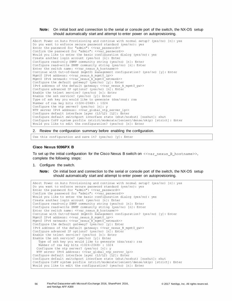
56 FlexPod Datacenter with Microsof t Exchange 2016, SharePoint 2016,
and NetApp AFF A300 © 2017 NetApp, Inc. All rights reserv ed.
Note: On initial boot and connection to the serial or console port of the switch, the NX-OS setup should automatically start and attempt to enter power on autoprovisioning.
Abort Power on Auto Provisioning and continue with normal setup? (yes/no) [n]: yes
Do you want to enforce secure password standard (yes/no): yes
Enter the password for "admin": <<var_password>>
Confirm the password for "admin": <<var_password>>
Would you like to enter the basic configuration dialog (yes/no): yes
Create another login account (yes/no) [n]: Enter
Configure read-only SNMP community string (yes/no) [n]: Enter
Configure read-write SNMP community string (yes/no) [n]: Enter
Enter the switch name: <<var_nexus_A_hostname>>
Continue with Out-of-band (mgmt0) management configuration? (yes/no) [y]: Enter
Mgmt0 IPv4 address: <<var_nexus_A_mgmt0_ip>>
Mgmt0 IPv4 netmask: <<var_nexus_A_mgmt0_netmask>>
Configure the default gateway? (yes/no) [y]: Enter
IPv4 address of the default gateway: <<var_nexus_A_mgmt0_gw>>
Configure advanced IP options? (yes/no) [n]: Enter
Enable the telnet service? (yes/no) [n]: Enter
Enable the ssh service? (yes/no) [y]: Enter
Type of ssh key you would like to generate (dsa/rsa): rsa
Number of rsa key bits <1024-2048> : 1024
Configure the ntp server? (yes/no) [n]: y
NTP server IPv4 address: <<var_global_ntp_server_ip>>
Configure default interface layer (L3/L2) [L2]: Enter
Configure default switchport interface state (shut/noshut) [noshut]: shut
Configure CoPP system profile (strict/moderate/lenient/dense/skip) [strict]: Enter
Would you like to edit the configuration? (yes/no) [n]: Enter
2. Review the configuration summary before enabling the configuration.
Use this configuration and save it? (yes/no) [y]: Enter
Cisco Nexus 9396PX B
To set up the initial configuration for the Cisco Nexus B switch on <<var_nexus_B_hostname>>,
complete the following steps:
1. Configure the switch.
Note: On initial boot and connection to the serial or console port of the switch, the NX-OS setup should automatically start and attempt to enter power on autoprovisioning.
Abort Power on Auto Provisioning and continue with normal setup? (yes/no) [n]: yes
Do you want to enforce secure password standard (yes/no): yes
Enter the password for "admin": <<var_password>>
Confirm the password for "admin": <<var_password>>
Would you like to enter the basic configuration dialog (yes/no): yes
Create another login account (yes/no) [n]: Enter
Configure read-only SNMP community string (yes/no) [n]: Enter
Configure read-write SNMP community string (yes/no) [n]: Enter
Enter the switch name: <<var_nexus_B_hostname>>
Continue with Out-of-band (mgmt0) management configuration? (yes/no) [y]: Enter
Mgmt0 IPv4 address: <<var_nexus_B_mgmt0_ip>>
Mgmt0 IPv4 netmask: <<var_nexus_B_mgmt0_netmask>>
Configure the default gateway? (yes/no) [y]: Enter
IPv4 address of the default gateway: <<var_nexus_B_mgmt0_gw>>
Configure advanced IP options? (yes/no) [n]: Enter
Enable the telnet service? (yes/no) [n]: Enter
Enable the ssh service? (yes/no) [y]: Enter
Type of ssh key you would like to generate (dsa/rsa): rsa
Number of rsa key bits <1024-2048> : 1024
Configure the ntp server? (yes/no) [n]: y
NTP server IPv4 address: <<var_global_ntp_server_ip>>
Configure default interface layer (L3/L2) [L2]: Enter
Configure default switchport interface state (shut/noshut) [noshut]: shut
Configure CoPP system profile (strict/moderate/lenient/dense/skip) [strict]: Enter
Would you like to edit the configuration? (yes/no) [n]: Enter

57 FlexPod Datacenter with Microsof t Exchange 2016, SharePoint 2016,
and NetApp AFF A300 © 2017 NetApp, Inc. All rights reserv ed.
2. Review the configuration summary before enabling the configuration.
Use this configuration and save it? (yes/no) [y]: Enter
FlexPod Cisco Nexus iSCSI Storage vSphere on ONTAP
This section describes how to configure the FlexPod environment for iSCSI.
Enable Licenses
Cisco Nexus 9396PX A and Cisco Nexus 9396PX B
To license the Cisco Nexus switches, complete the following steps on both switches:
1. Log in as an administrator.
2. Run the following commands:
config t
feature interface-vlan
feature lacp
feature vpc
feature lldp
Set Global Configurations
Cisco Nexus 9396PX A and Cisco Nexus 9396PX B
To set global configurations, run the following commands on both switches to set global configurations
and jumbo frames in QoS:
spanning-tree port type network default
spanning-tree port type edge bpduguard default
spanning-tree port type edge bpdufilter default
port-channel load-balance src-dst l4port
ntp server <<var_global_ntp_server_ip>> use-vrf default
ntp source <var_switch_ntp_ip>
ntp master 3
ip route 0.0.0.0/0 <<var_ib-mgmt-vlan_gateway>>
copy run start
Create VLANs
Cisco Nexus 9396PX A and Cisco Nexus 9396PX B
To create the necessary VLANs, run the following commands from the global configuration mode on both
switches:
vlan <<var_ib-mgmt_vlan_id>>
name IB-MGMT-VLAN
exit
vlan <<var_native_vlan_id>>
name Native-VLAN
exit
vlan <<var_vmotion_vlan_id>>
name vMotion-VLAN
exit
vlan <<var_nfs_vlan_id>>
name NFS-VLAN
exit
vlan <<var_iscsi-a_vlan_id>>
name iSCSI-A-VLAN
exit
vlan <<var_iscsi-b_vlan_id>>
name iSCSI-B-VLAN

58 FlexPod Datacenter with Microsof t Exchange 2016, SharePoint 2016,
and NetApp AFF A300 © 2017 NetApp, Inc. All rights reserv ed.
exit
Add NTP Distribution Interface
Cisco Nexus 9396PX A and Cisco Nexus 9396PX B
From the global configuration mode, run the following commands:
interface Vlan<<var_ib-mgmt_vlan_id>>
ip address <var_switch_ntp_ip>/<var_ib-mgmt_vlan_netmask_length>
no shutdown
exit
Add Individual Port Descriptions for Troubleshooting
Cisco Nexus 9396PX A
To add individual port descriptions for troubleshooting activity and verification for switch A, run the
following commands from the global configuration mode:
interface Eth1/1
description <<var_ucs_clustername>>-A:1/31
exit
interface Eth1/2
description <<var_ucs_clustername>>-B:1/31
exit
interface Eth1/3
description <<var_ucs_clustername>>-A:1/29
exit
interface Eth1/4
description <<var_ucs_clustername>>-B:1/29
exit
interface Eth1/5
description <<var_node01>>:e0e
exit
interface Eth1/6
description <<var_node01>>:e0g
exit
interface Eth1/7
description <<var_node02>>:e0e
exit
interface Eth1/8
description <<var_node02>>:e0g
exit
interface Eth1/47
description <<var_nexus_B_hostname>>:1/47
exit
interface Eth1/48
description <<var_nexus_B_hostname>>:1/48
exit
Cisco Nexus 9396PX B
To add individual port descriptions for troubleshooting activity and verification for switch B, run the
following commands from the global configuration mode:
interface Eth1/1
description <<var_ucs_clustername>>-A:1/32
exit
interface Eth1/2
description <<var_ucs_clustername>>-B:1/32
exit
interface Eth1/3
description <<var_ucs_clustername>>-A:1/30
exit
interface Eth1/4

59 FlexPod Datacenter with Microsof t Exchange 2016, SharePoint 2016,
and NetApp AFF A300 © 2017 NetApp, Inc. All rights reserv ed.
description <<var_ucs_clustername>>-B:1/30
exit
interface Eth1/5
description <<var_node01>>:e0f
exit
interface Eth1/6
description <<var_node01>>:e0h
exit
interface Eth1/7
description <<var_node02>>:e0f
exit
interface Eth1/8
description <<var_node02>>:e0h
exit
interface Eth1/47
description <<var_nexus_A_hostname>>:1/47
exit
interface Eth1/48
description <<var_nexus_A_hostname>>:1/48
exit
Create Port Channels
Cisco Nexus 9396PX A and Cisco Nexus 9396PX B
To create the necessary port channels between devices, run the following commands from the global
configuration mode:
interface Po10
description vPC peer-link
exit
interface Eth1/47-48
channel-group 10 mode active
no shutdown
exit
interface Po11
description <<var_node01>>
exit
interface Eth1/5-6
channel-group 11 mode active
no shutdown
exit
interface Po12
description <<var_node02>>
exit
interface Eth1/7-8
channel-group 12 mode active
no shutdown
exit
interface Po13
description <<var_ucs_clustername>>-A
exit
interface Eth1/1
channel-group 13 mode active
no shutdown
exit
interface Eth1/3
channel-group 13 mode active
no shutdown
exit
interface Po14
description <<var_ucs_clustername>>-B
exit
interface Eth1/2
channel-group 14 mode active
no shutdown
exit
interface Eth1/4
channel-group 14 mode active

60 FlexPod Datacenter with Microsof t Exchange 2016, SharePoint 2016,
and NetApp AFF A300 © 2017 NetApp, Inc. All rights reserv ed.
no shutdown
exit
copy run start
Configure Port Channels for Cisco Nexus 9396PX A and Cisco Nexus 9396PX B
To configure port channel parameters, run the following commands from the global configuration mode on
both switches:
interface Po10
switchport mode trunk
switchport trunk native vlan <<var_native_vlan_id>>
switchport trunk allowed vlan <<var_ib-mgmt_vlan_id>>, <<var_nfs_vlan_id>>,
<<var_vmotion_vlan_id>>, <<var_iscsi-a_vlan_id>>, <<var_iscsi-b_vlan_id>>
spanning-tree port type network
exit
interface Po11
switchport mode trunk
switchport trunk native vlan <<var_native_vlan_id>>
switchport trunk allowed vlan <<var_nfs_vlan_id>>, <<var_iscsi-a_vlan_id>>, <<var_iscsi-
b_vlan_id>>
spanning-tree port type edge trunk
mtu 9216
exit
interface Po12
switchport mode trunk
switchport trunk native vlan <<var_native_vlan_id>>
switchport trunk allowed vlan <<var_nfs_vlan_id>>, <<var_iscsi-a_vlan_id>>, <<var_iscsi-
b_vlan_id>>
spanning-tree port type edge trunk
mtu 9216
exit
interface Po13
switchport mode trunk
switchport trunk native vlan <<var_native_vlan_id>>
switchport trunk allowed vlan <<var_ib-mgmt_vlan_id>>, <<var_nfs_vlan_id>>,
<<var_vmotion_vlan_id>>, <<var_iscsi-a_vlan_id>>, <<var_iscsi-b_vlan_id>>
spanning-tree port type edge trunk
mtu 9216
exit
interface Po14
switchport mode trunk
switchport trunk native vlan <<var_native_vlan_id>>
switchport trunk allowed vlan <<var_ib-mgmt_vlan_id>>, <<var_nfs_vlan_id>>,
<<var_vmotion_vlan_id>>, <<var_iscsi-a_vlan_id>>, <<var_iscsi-b_vlan_id>>
spanning-tree port type edge trunk
mtu 9216
exit
copy run start
Configure Virtual Port Channels for Cisco Nexus 9396PX A
To configure virtual port channels (vPCs) for switch A, run the following commands from the global
configuration mode:
vpc domain <<var_nexus_vpc_domain_id>>
role priority 10
peer-keepalive destination <<var_nexus_B_mgmt0_ip>> source <<var_nexus_A_mgmt0_ip>>
peer-switch
peer-gateway
delay restore 150
auto-recovery
exit

61 FlexPod Datacenter with Microsof t Exchange 2016, SharePoint 2016,
and NetApp AFF A300 © 2017 NetApp, Inc. All rights reserv ed.
interface Po10
vpc peer-link
exit
interface Po11
vpc 11
exit
interface Po12
vpc 12
exit
interface Po13
vpc 13
exit
interface Po14
vpc 14
exit
copy run start
Configure Virtual Port Channels for Cisco Nexus 9396PX B
To configure vPCs for switch B, run the following commands from the global configuration mode:
vpc domain <<var_nexus_vpc_domain_id>>
role priority 20
peer-keepalive destination <<var_nexus_A_mgmt0_ip>> source <<var_nexus_B_mgmt0_ip>>
peer-switch
peer-gateway
delay restore 150
auto-recovery
exit
interface Po10
vpc peer-link
exit
interface Po11
vpc 11
exit
interface Po12
vpc 12
exit
interface Po13
vpc 13
exit
interface Po14
vpc 14
exit
copy run start
Note: Remember to run copy run start to permanently save the switch configurations.
Uplink into Existing Network Infrastructure
Depending on the available network infrastructure, several methods and features can be used to uplink
the FlexPod environment. If an existing Cisco Nexus environment is present, NetApp recommends using
vPCs to uplink the Cisco Nexus 9396PX switches included in the FlexPod environment into the
infrastructure. The previous procedures can be used to create an uplink vPC to the existing environment.
Make sure to run copy run start to save the configuration on each switch after the configuration is
completed.

62 FlexPod Datacenter with Microsof t Exchange 2016, SharePoint 2016,
and NetApp AFF A300 © 2017 NetApp, Inc. All rights reserv ed.
5.4 VMware vSphere Configuration
This section describes how to configure VMware vSphere 6.5.
FlexPod VMware ESXi 6.5 on ONTAP
The procedures in the following sections provide detailed instructions for installing VMware ESXi 6.5 in a
FlexPod environment. This procedure assumes that the ESXi host service profiles have been created and
that boot LUNs have been created and mapped to each host. After the procedures are completed, eight
iSCSI-booted ESXi hosts must be provisioned. These procedures are customized to include the
environment variables.
Note: Several methods exist for installing ESXi in a VMware environment. The procedures in this section focus on how to use the built-in KVM console and virtual media features in Cisco UCS Manager to map remote installation media to individual servers and connect to their iSCSI boot LUNs.
Open Cisco UCS IP KVM Console for Each Blade
The IP KVM enables the administrator to begin the installation of the operating system through remote
media. You must log in to the Cisco UCS environment to run the IP KVM.
To log in to the Cisco UCS environment, complete the following steps:
1. Open a web browser and enter the IP address of the Cisco UCS cluster. This step launches the Cisco
UCS Manager application.
2. If prompted to accept security certificates, accept as necessary.
3. When prompted, enter admin as the user name and enter the administrative password.
4. To log in to Cisco UCS Manager, click Login.
5. From the main menu, click the Servers tab.
6. Select Servers > Service Profiles > Root > VM-Host-Infra-01.
7. Right-click VM-Host-Infra-01 and select KVM Console.
8. If prompted to accept an unencrypted KVM session, accept as necessary.
9. Repeat for each host to be installed.
Set Up VMware ESXi Installation
To prepare the server for the operating system installation, complete the following steps on each ESXi
host:
1. In the KVM window, click the Virtual Media node.
2. If prompted to accept an unencrypted KVM session, accept as necessary.
3. Click Add Image.
4. Browse to the ESXi installer ISO image file and click Open.
5. Select the Mapped checkbox to map the newly added image.
6. Click the KVM tab to monitor the server boot.
7. Boot the server by selecting Boot Server and clicking OK.
8. Click OK again.
Install ESXi
To install VMware ESXi to the iSCSI LUN that was prepared for each host, complete the following steps
on each host:

63 FlexPod Datacenter with Microsof t Exchange 2016, SharePoint 2016,
and NetApp AFF A300 © 2017 NetApp, Inc. All rights reserv ed.
1. On reboot, the machine detects the presence of the ESXi installation media. Select the ESXi installer
from the boot menu that is displayed.
2. After the installer is finished loading, press Enter to continue with the installation.
3. Read and accept the end-user license agreement (EULA). Press F11 to accept and continue.
4. Select NETAPP LUN C-mode as the installation disk for ESXi and press Enter to continue with the
installation.
5. Select the appropriate keyboard layout and press Enter.
6. Enter and confirm the root password and press Enter.
7. The installer issues a warning that the selected disk will be repartitioned. Press F11 to continue with
the installation.
8. After the installation is complete, click the Virtual Media tab and clear the checkmark next to the ESXi
installation media. Click Yes.
Note: The ESXi installation image must be unmapped so that the server reboots into ESXi and not into the installer.
9. From the KVM tab, press Enter to reboot the server.
Set Up Management Networking for ESXi Hosts
Adding a management network for each VMware host is necessary for managing the hosts. To configure
the ESXi hosts with access to the management network, complete the following steps:
1. After the server has finished rebooting, press F2 to customize the system.
2. Use root as the login name, enter the corresponding password, and press Enter to log in.
3. Select the Configure the Management Network option and press Enter.
4. Select the VLAN (Optional) option and press Enter.
5. Enter <<var_mgmt_vlan_id>> and press Enter.
6. From the Configure Management Network menu, select IP Configuration and press Enter.
7. Using the spacebar, select the Set Static IP Address and Network Configuration option.
8. Enter the IP address for managing the ESXi host.
9. Enter the subnet mask for the ESXi host.
10. Enter the default gateway for the ESXi host.
11. Press Enter to accept the changes to the IP configuration.
12. Select the IPv6 Configuration option and press Enter.
13. Using the spacebar, unselect Enable IPv6 (restart required) and press Enter.
14. Select the DNS Configuration option and press Enter.
Note: Because the IP address is assigned manually, the DNS information must also be entered manually.
15. Enter the IP address of the primary DNS server.
16. Optional: Enter the IP address of the secondary DNS server.
17. Enter the FQDN for the ESXi host.
18. Press Enter to accept the changes to the DNS configuration.
19. Press Esc to exit the Configure Management Network submenu.
20. Press Y to confirm the changes and return to the main menu.
21. The ESXi host reboots. After reboot, press F2 and log in as root again.

64 FlexPod Datacenter with Microsof t Exchange 2016, SharePoint 2016,
and NetApp AFF A300 © 2017 NetApp, Inc. All rights reserv ed.
22. Select Test Management Network to verify that the management network is set up correctly and
press Enter.
23. Press Enter to run the test.
24. Press Enter to exit the window.
25. Press Esc to log out of the VMware console.
Log in to VMware ESXi Hosts by Using VMware Host Client
To log in to the VM-Host-Infra-01 ESXi host, complete the following steps:
1. Open a web browser on the management workstation and navigate to the VM-Host-Infra-
01 management IP address.
2. Click Open the VMware Host Client.
3. Enter root for the user name.
4. Enter the root password.
5. Click Login to connect.
6. Repeat this process to log in to other hosts in separate browser tabs or windows.
Set Up VMkernel Ports and Virtual Switch
To set up the VMkernel ports and the virtual switches on the ESXi hosts, complete the following steps:
1. From the Host Client, select Networking on the left.
2. In the center pane, select the Virtual switches tab.
3. Select vSwitch0.
4. Select Edit settings.
5. Change the MTU to 9000.
6. Click Add uplink and then select vmnic1 from the drop-down box.
7. Click Save.
8. Select Networking on the left.
9. In the center pane, select the Virtual switches tab.
10. Select iScsiBootvSwitch.
11. Select Edit settings.
12. Change the MTU to 9000.
13. Click Save.
14. Select Networking on the left.
15. Select the VMkernel NICs tab.
16. Select vmk1 iScsiBootPG.
17. Select Edit settings.
18. Change the MTU to 9000.
19. Click Save.
20. Select Networking on the left.
21. Select the Virtual switches tab.
22. Select the Add standard virtual switch.
23. Provide a name of iScsciBootvSwitch-B for the vSwitch name.
24. Set the MTU to 9000.

65 FlexPod Datacenter with Microsof t Exchange 2016, SharePoint 2016,
and NetApp AFF A300 © 2017 NetApp, Inc. All rights reserv ed.
25. Select vmnic3 from the Uplink 1 pull-down options.
26. Click Add.
27. In the center pane, select the VMkernel NICs tab.
28. Select Add VMkernel NIC.
29. Specify a new port group name of iScsiBootPG-B.
30. Select iScsciBootvSwitch-B for Virtual switch.
31. Set the MTU to 9000. Do not enter a VLAN ID.
32. Select Static for the IPv4 settings and expand the option to provide the Address and Subnet Mask
within the Configuration.
33. Click Create.
34. On the left, select Networking, then select the Port groups tab.
35. In the center pane, right-click VM Network and select Remove.
36. Click Remove to complete removing the port group.
37. In the center pane, select Add port group.
38. Name the port group MGMT Network, enter <<mgmt-vlan-id>> in the VLAN ID field, and make
sure Virtual switch vSwitch0 is selected.
39. Click Add to finalize the edits for the MGMT Network.
40. At the top, select the VMkernel NICs tab.
41. Click Add VMkernel NIC.
42. In the New Port Group field, enter VMkernel-vMotion.
43. For the virtual switch, select vSwitch0 selected.
44. Enter <vmotion-vlan-id> for the VLAN ID.
45. Change the MTU to 9000.
46. Select Static IPv4 settings and expand IPv4 settings.
47. Enter the ESXi host vMotion IP address and netmask.
48. Select the vMotion stack TCP/IP stack.
49. Under Services, select vMotion.
50. Click Create.
51. Click Add VMkernel NIC.
52. In the New Port Group field, enter VMkernel-NFS.
53. For the virtual switch, select vSwitch0 selected.
54. Enter <nfs-vlan-id> for the VLAN ID.
55. Change the MTU to 9000.
56. Select Static IPv4 settings and expand IPv4 settings.
57. Enter the ESXi host infrastructure NFS IP address and netmask.
58. Do not select any of the services.
59. Click Create.
60. Click the Port Groups tab.
61. In the center pane, select Add Port Group.
62. Name the port group iSCSIA Network, do not enter a VLAN ID field, and make sure Virtual switch
iScsiBootvSwitch is selected.
63. Click Add to finalize the edits for the iSCSIA Network.

66 FlexPod Datacenter with Microsof t Exchange 2016, SharePoint 2016,
and NetApp AFF A300 © 2017 NetApp, Inc. All rights reserv ed.
64. In the center pane, select Add port group.
65. Name the port group iSCSIB Network but do not enter a VLAN ID field. Make sure that the virtual
switch iScsiBootvSwitch-B is selected.
66. Click Add to finalize the edits for the iSCSIB network.
67. Select the Virtual Switches tab, then vSwitch0. The properties for vSwitch0 VMkernel NICs should be
similar to the following example:
68. Select the VMkernel NICs tab to confirm configured virtual adapters. The adapters listed should be
similar to the following example:
Set Up iSCSI Multipathing
To set up the iSCSI multipathing on the ESXi hosts, complete the following steps:
1. From each host client, select Storage in the left pane.
2. In the center pane, click Adapters.
3. Select the iSCSI software adapter and click Configure iSCSI.
4. Under Dynamic Targets, click Add Dynamic Target.
5. Enter the IP address of iSCSI_lif01a.

67 FlexPod Datacenter with Microsof t Exchange 2016, SharePoint 2016,
and NetApp AFF A300 © 2017 NetApp, Inc. All rights reserv ed.
6. Repeat steps 1 through 5 using each of these IP addresses: iscsi_lif01b, iscsi_lif02a, and
iscsi_lif02b.
7. Click Save Configuration.
Note: To get the complete iscsi_lif IP address, log in to the NetApp storage cluster management interface and type the “network interface show” command.
Note: The host automatically rescans the storage adapter, and the targets are added to static targets.
Mount Required Datastores
To mount the required datastores, complete the following steps on each ESXi host:
1. From the host client, select Storage in the left pane.
2. In the center pane, select Datastores.
3. In the center pane, select New Datastore to add a new datastore.
4. In the New Datastore message, select Mount NFS Datastore and click Next.

68 FlexPod Datacenter with Microsof t Exchange 2016, SharePoint 2016,
and NetApp AFF A300 © 2017 NetApp, Inc. All rights reserv ed.
5. Enter infra_datastore_1 for the datastore name. Enter the IP address for the nfs_lif01 LIF for
the NFS server. Enter /infra_datastore_1 for the NFS share. Leave the NFS version set at NFS.
Click Next.
6. Click Finish. The datastore should now appear in the datastore list.
7. In the center pane, select New Datastore to add a new datastore.
8. In the new datastore message, select Mount NFS datastore and click Next.
9. Enter infra_swap for the datastore name. Enter the IP address for the nfs_lif02 LIF for the NFS
server. Enter /infra_swap for the NFS share. Leave the NFS version set at NFS 3. Click Next.
10. Click Finish. The datastore should now appear in the datastore list.
11. Repeat steps 1 through 10 to mount the VM datastore on all of the ESXi hosts.
Configure NTP on ESXi Hosts
To configure NTP on the ESXi hosts, complete the following steps on each host:
1. From the host client, select Manage in the left pane.
2. In the center pane, select the Time & Date tab.
3. Click Edit settings.
4. Make sure Use Network Time Protocol (enable NTP client) is selected.
5. From the drop-down menu, select Start and Stop with Host.
6. Enter the IP address for the NTP server.

69 FlexPod Datacenter with Microsof t Exchange 2016, SharePoint 2016,
and NetApp AFF A300 © 2017 NetApp, Inc. All rights reserv ed.
7. Click Save to save the configuration changes.
8. Select Actions > NTP Service > Start.
9. Verify that NTP service is now running and that the clock is set to approximately the correct time.
Note: The NTP server time might vary slightly from the host time.
Move VM Swap File Location for Infrastructure Hosts
To configure NTP on the ESXi hosts, complete the following steps on each host:
1. From the host client, select Manage in the left pane.
2. In the center pane, select the Swap tab.
3. Click Edit settings.
4. Select infra_swap from the datastore drop-down menu.
5. Click Save to save the configuration changes.
5.5 VMware vCenter 6.5a Configuration
The procedures in the following subsections provide detailed instructions for installing the VMware
vCenter 6.5a Server Appliance in an environment. After completing the installation procedure, you need
to configure the VMware vCenter Server.
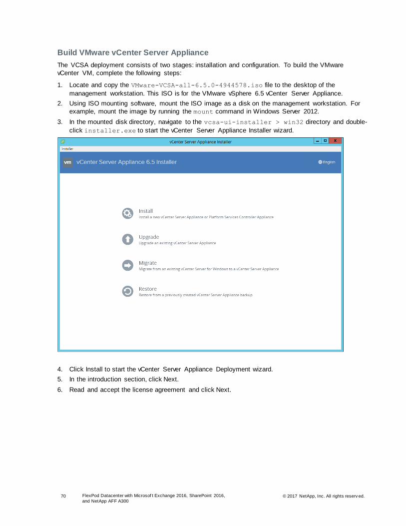
70 FlexPod Datacenter with Microsof t Exchange 2016, SharePoint 2016,
and NetApp AFF A300 © 2017 NetApp, Inc. All rights reserv ed.
Build VMware vCenter Server Appliance
The VCSA deployment consists of two stages: installation and configuration. To build the VMware
vCenter VM, complete the following steps:
1. Locate and copy the VMware-VCSA-all-6.5.0-4944578.iso file to the desktop of the
management workstation. This ISO is for the VMware vSphere 6.5 vCenter Server Appliance.
2. Using ISO mounting software, mount the ISO image as a disk on the management workstation. For
example, mount the image by running the mount command in Windows Server 2012.
3. In the mounted disk directory, navigate to the vcsa-ui-installer > win32 directory and double-
click installer.exe to start the vCenter Server Appliance Installer wizard.
4. Click Install to start the vCenter Server Appliance Deployment wizard.
5. In the introduction section, click Next.
6. Read and accept the license agreement and click Next.

71 FlexPod Datacenter with Microsof t Exchange 2016, SharePoint 2016,
and NetApp AFF A300 © 2017 NetApp, Inc. All rights reserv ed.
7. In the Select Deployment Type section, select Embedded Platform Services Controller.
8. In the Appliance Deployment Target fields, enter the ESXi host name or IP address, user name, and
password.
9. Click Yes to accept the certificate.
10. In the Set Up Appliance VM section, enter the appliance name and password. Click Next.

72 FlexPod Datacenter with Microsof t Exchange 2016, SharePoint 2016,
and NetApp AFF A300 © 2017 NetApp, Inc. All rights reserv ed.
11. In the Select Deployment Size section, select the deployment size and storage size (for example,
select Small). Click Next.
12. Select the infra_datastore_1 and click Next.
13. In the Network Settings section, configure the following settings and then click Next:
a. Choose a network: IB-MGMT Network
b. IP version: IPV4
c. IP assignment: static
d. System name: <vcenter-fqdn-or-ip>
e. IP address: <vcenter-ip>
f. Subnet mask or prefix length: <vcenter-subnet-mask>
g. Default gateway: <vcenter-gateway>
h. DNS servers: <dns-server>
14. Review all of the values and click Finish to complete the installation.
15. The vCenter appliance installation takes a few minutes to complete.
16. Click Continue to proceed with stage two of the configuration.
17. Click Next.
18. In the Appliance Configuration section, configure the following settings and then click Next:
a. Time synchronization mode: synchronize time with NTP servers
b. NTP servers: <ntp_server_ip>
c. SSH access: enabled
19. Complete the single sign-on (SSO) configuration and click Next.

73 FlexPod Datacenter with Microsof t Exchange 2016, SharePoint 2016,
and NetApp AFF A300 © 2017 NetApp, Inc. All rights reserv ed.
20. If needed, select Join the VMware’s Customer Experience Improvement Program (CEIP) and click
Next.
21. Review the configuration and click Finish.
22. Click OK.
Set Up VMware vCenter Server
To set up the VMware vCenter Server, complete the following steps:
1. Using a web browser, navigate to https://<vcenter-ip>/vsphere-client.
2. Click Download Enhanced Authentication Plugin and then install by double-clicking the downloaded
file.
3. Log in using the SSO user name and password created during the vCenter installation.
4. In the center pane, click Create Datacenter.
5. In the Datacenter Name field, enter FlexPod-DC and click OK.
6. In the center pane, right-click the FlexPod-DC data center from the list. Click New Cluster.
7. Name the cluster FlexPod-Cluster.
8. Select the Turn On option for DRS and then leave the default values.
9. Select the Turn On option for vSphere HA and then leave the default values.

74 FlexPod Datacenter with Microsof t Exchange 2016, SharePoint 2016,
and NetApp AFF A300 © 2017 NetApp, Inc. All rights reserv ed.
10. Click OK to create the new cluster.
11. In the left pane, right-click FlexPod-Management and click Add Host.
12. In the Host field, enter either the IP address or the FQDN name of one of the VMware ESXi hosts.
Click Next.
13. Enter root as the user name and the root password. Click Next.
14. Click Yes to accept the certificate.
15. Review the host details and click Next.
16. Assign a license or leave in evaluation mode and then click Next.
17. Click Next.
18. Click Next again.
19. Review the configuration parameters. Click Finish to add the host.

75 FlexPod Datacenter with Microsof t Exchange 2016, SharePoint 2016,
and NetApp AFF A300 © 2017 NetApp, Inc. All rights reserv ed.
20. Repeat steps 1 through 19 to add the remaining VMware ESXi hosts to the cluster.
5.6 NetApp VSC 6.2.1 Deployment Procedure
This section describes the deployment procedures for the VSC.
VSC 6.2.1 Preinstallation Considerations
The following licenses are required for VSC on storage systems that run ONTAP 9.1:
• Protocol licenses (NFS and iSCSI)
• NetApp FlexClone (for provisioning and cloning only)
• NetApp SnapRestore (for backup and recovery)
• NetApp SnapManager Suite
Install VSC 6.2.1
To install the VSC 6.2.1 software, complete the following steps:
1. Build a VSC VM with Windows Server 2016, 4GB of RAM, two CPUs, and one virtual network
interface in the MGMT Network port group. The virtual network interface should be a VMXNET 3
adapter.
2. Bring up the VM, install VMware Tools, assign the IP address and gateway in the MGMT subnet, and
join the machine to the Active Directory (AD) domain.
3. Install all Windows updates on the VM.
4. Log in to the VSC VM as the FlexPod admin user by using the VMware console.
5. From the VMware console on the VSC VM, download the x64 version of Virtual Storage Console
6.2.1P1 from the NetApp Support site.
6. Right-click the VSC-6.2.1-win64.exe and select Run as Administrator.
7. Select the appropriate language and click OK.
8. On the Installation wizard Welcome page, click Next.
9. Select the checkbox to accept the message and click Next.

76 FlexPod Datacenter with Microsof t Exchange 2016, SharePoint 2016,
and NetApp AFF A300 © 2017 NetApp, Inc. All rights reserv ed.
10. Click Next to accept the default installation location.
11. Click Install.
12. Click Finish.
Register VSC with vCenter Server
To register the VSC with the vCenter Server, complete the following steps:

77 FlexPod Datacenter with Microsof t Exchange 2016, SharePoint 2016,
and NetApp AFF A300 © 2017 NetApp, Inc. All rights reserv ed.
1. A browser window with the registration URL opens automatically when the installation phase is complete. If the URL does not open automatically, open https://localhost:8143/Register.html in
Internet Explorer.
2. Click Continue to This Website (Not Recommended).
3. In the Plug-in Service Information section, select the local IP address of the VSC VM.
4. In the vCenter Server Information section, enter the host name or IP address, the user name (FlexPod admin user or root), and the user password for the vCenter Server. Click Register to
complete the registration.
5. With a successful registration, the storage controller discovery automatically begins.
Install NetApp NFS VAAI Plug-In
To install the NetApp NFS VAAI Plug-In, complete the following steps:
1. Download the NetApp NFS Plug-In 1.1.2 for VMware .vib file from the NFS plug-in download on the
VSC VM.
2. Rename the downloaded file NetAppNasPlugin.vib.
3. Move the file to the C:\Program Files\NetApp\Virtual Storage Console\etc\vsc\web
folder.
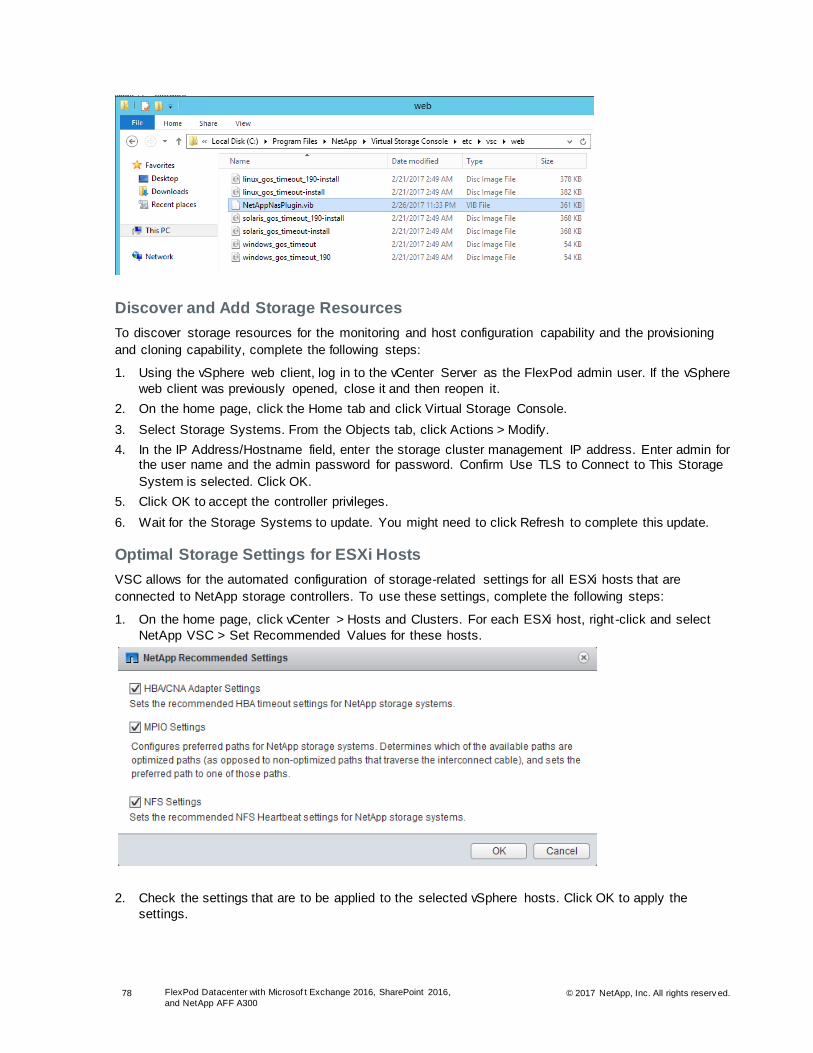
78 FlexPod Datacenter with Microsof t Exchange 2016, SharePoint 2016,
and NetApp AFF A300 © 2017 NetApp, Inc. All rights reserv ed.
Discover and Add Storage Resources
To discover storage resources for the monitoring and host configuration capability and the provisioning
and cloning capability, complete the following steps:
1. Using the vSphere web client, log in to the vCenter Server as the FlexPod admin user. If the vSphere
web client was previously opened, close it and then reopen it.
2. On the home page, click the Home tab and click Virtual Storage Console.
3. Select Storage Systems. From the Objects tab, click Actions > Modify.
4. In the IP Address/Hostname field, enter the storage cluster management IP address. Enter admin for the user name and the admin password for password. Confirm Use TLS to Connect to This Storage
System is selected. Click OK.
5. Click OK to accept the controller privileges.
6. Wait for the Storage Systems to update. You might need to click Refresh to complete this update.
Optimal Storage Settings for ESXi Hosts
VSC allows for the automated configuration of storage-related settings for all ESXi hosts that are
connected to NetApp storage controllers. To use these settings, complete the following steps:
1. On the home page, click vCenter > Hosts and Clusters. For each ESXi host, right-click and select
NetApp VSC > Set Recommended Values for these hosts.
2. Check the settings that are to be applied to the selected vSphere hosts. Click OK to apply the
settings.

79 FlexPod Datacenter with Microsof t Exchange 2016, SharePoint 2016,
and NetApp AFF A300 © 2017 NetApp, Inc. All rights reserv ed.
Note: This functionality sets values for HBAs and converged network adapters (CNAs), sets appropriate paths and path-selection plug-ins, and verifies appropriate settings for software-based I/O (NFS and iSCSI).
3. Click OK.
4. On the home page, in the vSphere Web Client, select Virtual Storage Console.
5. On the left pane, under Virtual Storage Console, select NFS VAAI Tools.
6. Make sure that NFS Plug-in for VMware VAII Version 1.1.2-3 is shown.
7. Click Install on Host.
8. Select all the ESXi hosts and click Install.
9. For each host for which settings were adjusted in the previous step, place the host in maintenance
mode, reboot the host, and exit maintenance mode.
5.7 Service Accounts Creation
This section describes the service accounts that are required to install SQL Server, SharePoint 2016, and
Exchange 2016.
Provision the user accounts and user groups listed in Table 13 and Table 14.
Table 13 ) Service user accounts.
Component User Account Suggested
Name Description
SQL, SharePoint Component
installation account SPInstall This optional account is used to install all
SharePoint and SQL Server components.
SQL Server SQL Server instance service account
SPSQLSvc This account is used as the service account for all instances of SQL Server.
SharePoint SharePoint farm account
SPFarm This account is used to access the SQL database and run all core farm services.
SQL, DocAve, Exchange
SnapDrive service account
SDWSvc This account is used to run the SnapDrive service.
DocAve DocAve DocAveSvc This account is used to run the DocAve IIS application pool.
Exchange SnapManager for Exchange
SMESvc This account is used to run the SnapManager for Exchange service.
Note: The DocAveSvc account should be a part of the local administrator group on the DocAve Manager VM.
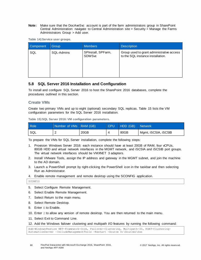
80 FlexPod Datacenter with Microsof t Exchange 2016, SharePoint 2016,
and NetApp AFF A300 © 2017 NetApp, Inc. All rights reserv ed.
Note: Make sure that the DocAveSvc account is part of the farm administrators group in SharePoint Central Administration: navigate to Central Administration site > Security > Manage the Farms Administrators Group > Add user.
Table 14) Service user groups.
Component Group Members Description
SQL SQL-Admins SPInstall, SPFarm, SDWSvc
Group used to grant administrative access to the SQL instance installation.
5.8 SQL Server 2016 Installation and Configuration
To install and configure SQL Server 2016 to host the SharePoint 2016 databases, complete the
procedures outlined in this section.
Create VMs
Create two primary VMs and up to eight (optional) secondary SQL replicas. Table 15 lists the VM
configuration parameters for the SQL Server 2016 installation.
Table 15) SQL Server 2016: VM configuration parameters.
Role Number of VMs RAM (GB) CPU HDD (GB) Network
SQL 2 20GB 4 80GB Mgmt, iSCSIA, iSCSIB
To prepare the VMs for SQL Server installation, complete the following steps:
1. Provision Windows Server 2016: each instance should have at least 20GB of RAM, four vCPUs, 80GB HDD and virtual network interfaces in the MGMT network, and iSCSIA and iSCSIB port groups.
The virtual network interfaces should be VMXNET 3 adapters.
2. Install VMware Tools, assign the IP address and gateway in the MGMT subnet, and join the machine
to the AD domain.
3. Launch a PowerShell prompt by right-clicking the PowerShell icon in the taskbar and then selecting
Run as Administrator.
4. Enable remote management and remote desktop using the SCONFIG application.
SCONFIG
5. Select Configure Remote Management.
6. Select Enable Remote Management.
7. Select Return to the main menu.
8. Select Remote Desktop.
9. Enter E to Enable.
10. Enter 2 to allow any version of remote desktop. You are then returned to the main menu.
11. Select Exit to Command Line.
12. Add the Windows failover clustering and multipath I/O features by running the following command:
Add-WindowsFeature NET-Framework-Core, Failover-Clustering, Multipath-IO, RSAT-Clustering-
AutomationServer -IncludeManagementTools -Restart -Source D:\Sources\Sxs
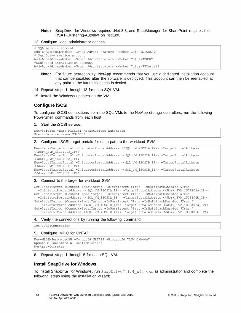
81 FlexPod Datacenter with Microsof t Exchange 2016, SharePoint 2016,
and NetApp AFF A300 © 2017 NetApp, Inc. All rights reserv ed.
Note: SnapDrive for Windows requires .Net 3.5, and SnapManager for SharePoint requires the RSAT-Clustering-Automation feature.
13. Configure local administrator access.
# SQL service account
Add-LocalGroupMember -Group Administrators -Member Colts\SPSQLSvc
# SnapDrive service account
Add-LocalGroupMember -Group Administrators -Member Colts\SDWSVC
#Dedicated installation account
Add-LocalGroupMember -Group Administrators -Member Colts\SPInstall
Note: For future serviceability, NetApp recommends that you use a dedicated installation account that can be disabled after the software is deployed. This account can then be reenabled at any point in the future if access is denied.
14. Repeat steps 1 through 13 for each SQL VM.
15. Install the Windows updates on the VM.
Configure iSCSI
To configure iSCSI connections from the SQL VMs to the NetApp storage controllers, run the following
PowerShell commands from each host:
1. Start the iSCSI service.
Set-Service -Name MSiSCSI -StartupType Automatic
Start-Service -Name MSiSCSI
2. Configure iSCSI target portals for each path to the workload SVM.
New-IscsiTargetPortal -InitiatorPortalAddress <<SQL_VM_iSCSIA_IP>> -TargetPortalAddress
<<Work_SVM_iSCSI01a_IP>>
New-IscsiTargetPortal -InitiatorPortalAddress <<SQL_VM_iSCSIA_IP>> -TargetPortalAddress
<<Work_SVM_iSCSI02a_IP>>
New-IscsiTargetPortal -InitiatorPortalAddress <<SQL_VM_iSCSIB_IP>> -TargetPortalAddress
<<Work_SVM_iSCSI01b_IP>>
New-IscsiTargetPortal -InitiatorPortalAddress <<SQL_VM_iSCSIB_IP>> -TargetPortalAddress
<<Work_SVM_iSCSI02b_IP>>
3. Connect to the target for workload SVM.
Get-IscsiTarget |Connect-IscsiTarget -IsPersistent $True -IsMultipathEnabled $True `
-InitiatorPortalAddress <<SQL_VM_iSCSIA_IP>> -TargetPortalAddress <<Work_SVM_iSCSI01a_IP>>
Get-IscsiTarget |Connect-IscsiTarget -IsPersistent $True -IsMultipathEnabled $True `
-InitiatorPortalAddress <<SQL_VM_iSCSIA_IP>> -TargetPortalAddress <<Work_SVM_iSCSI01b_IP>>
Get-IscsiTarget |Connect-IscsiTarget -IsPersistent $True -IsMultipathEnabled $True `
-InitiatorPortalAddress <<SQL_VM_iSCSIB_IP>> -TargetPortalAddress <<Work_SVM_iSCSI02a_IP>>
Get-IscsiTarget |Connect-IscsiTarget -IsPersistent $True -IsMultipathEnabled $True `
-InitiatorPortalAddress <<SQL_VM_iSCSIB_IP>> -TargetPortalAddress <<Work_SVM_iSCSI02b_IP>>
4. Verify the connections by running the following command:
Get-IscsiConnection
5. Configure MPIO for ONTAP.
New-MSDSMSupportedHW -VendorId NETAPP -ProductId "LUN C-Mode"
Update-MPIOClaimedHW -Confirm:$false
Restart-Computer
6. Repeat steps 1 through 5 for each SQL VM.
Install SnapDrive for Windows
To install SnapDrive for Windows, run SnapDrive7.1.4_x64.exe as administrator and complete the
following steps using the installation wizard:
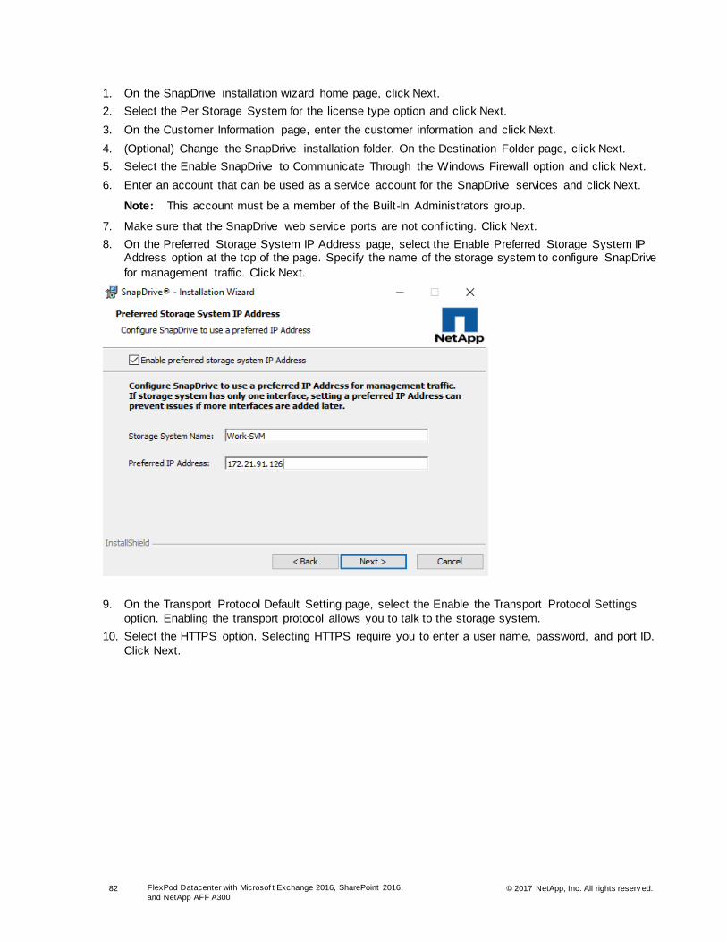
82 FlexPod Datacenter with Microsof t Exchange 2016, SharePoint 2016,
and NetApp AFF A300 © 2017 NetApp, Inc. All rights reserv ed.
1. On the SnapDrive installation wizard home page, click Next.
2. Select the Per Storage System for the license type option and click Next.
3. On the Customer Information page, enter the customer information and click Next.
4. (Optional) Change the SnapDrive installation folder. On the Destination Folder page, click Next.
5. Select the Enable SnapDrive to Communicate Through the Windows Firewall option and click Next.
6. Enter an account that can be used as a service account for the SnapDrive services and click Next.
Note: This account must be a member of the Built-In Administrators group.
7. Make sure that the SnapDrive web service ports are not conflicting. Click Next.
8. On the Preferred Storage System IP Address page, select the Enable Preferred Storage System IP Address option at the top of the page. Specify the name of the storage system to configure SnapDrive
for management traffic. Click Next.
9. On the Transport Protocol Default Setting page, select the Enable the Transport Protocol Settings
option. Enabling the transport protocol allows you to talk to the storage system.
10. Select the HTTPS option. Selecting HTTPS require you to enter a user name, password, and port ID.
Click Next.

83 FlexPod Datacenter with Microsof t Exchange 2016, SharePoint 2016,
and NetApp AFF A300 © 2017 NetApp, Inc. All rights reserv ed.
11. On the Unified Manager Configuration page, click Next.
12. Click Install to begin the SnapDrive installation.
13. Repeat steps 1 through 11 for each SQL node.
Mount Storage
In the previous subsection, you configured the iSCSI connections and installed SnapDrive on each of the
SQL VMs. In this section, you create and mount all of the external storage.
Table 16 lists the storage information for the SQL primary site.
Table 16) SQL primary site storage.
Server Volume Mount Point LUN Size
SQL01 SQL1_Data M:\ 500GB
SQL01 SQL1_Log L:\ 1TB
SQL01 SQL1_SharePoint N:\ 4TB
SQL01 SQL1_Snapinfo S:\ 1TB
SQL02 SQL2_Data M:\ 500GB
SQL02 SQL2_Log L:\ 1TB
SQL02 SQL2_SharePoint N:\ 4TB
SQL02 SQL2_Snapinfo S:\ 1TB
Note: NetApp recommends using SnapDrive for Windows to create the LUNs to house the databases and logs for your SQL Server instances. There are two methods available to create the LUNs: either use the SDW GUI or use the SnapDrive CLI (SDCLI). The following examples use the SDCLI method.

84 FlexPod Datacenter with Microsof t Exchange 2016, SharePoint 2016,
and NetApp AFF A300 © 2017 NetApp, Inc. All rights reserv ed.
1. Create SQL instance root LUN.
sdcli disk create -dtype dedicated -m SQL01 -D D:\ -p Work-
SVM.colts.local:/vol/SQL1_Data/Data.lun -I SQL01 iqn.1991-05.com.microsoft:sql01.colts.local -z
500G
2. Create SQL instance log LUN.
sdcli disk create -dtype dedicated -m SQL01 -D L:\ -p Work-SVM.colts.local:/vol/SQL1_Log/Log.lun
-I SQL01 iqn.1991-05.com.microsoft:sql01.colts.local -z 1T
3. Create SQL instance data LUN.
sdcli disk create -dtype dedicated -m SQL01 -D N:\ -p Work-
SVM.colts.local:/vol/SQL1_SharePoint/Data.lun -I SQL01 iqn.1991-
05.com.microsoft:sql01.colts.local -z 4T
4. Create SQL DocAve SnapInfo LUN.
sdcli disk create -dtype dedicated -m SQL01 -D D:\ -p Work-
SVM.colts.local:/vol/SQL1_Data/Data.lun -I SQL01 iqn.1991-05.com.microsoft:sql01.colts.local -z
1T
5. Confirm the LUNs have all been created and mounted to the appropriate path by running the
following SnapDrive PowerShell command:
Get-SdStorage
6. Repeat steps 1 through 5 on any of the remaining SQL Server instances, substituting as needed. At
a minimum, both of the primary site SQL Server instances must be prepared.
Create Windows Failover Cluster
To create a Windows failover cluster, complete the following steps:
1. On the Create Cluster wizard, click Next on the Before You Begin page.
2. On the Access Point for Administering the Cluster page, enter the cluster name, select the
appropriate network, provide the cluster IP address, and click Next.
3. On the Confirmation page, verify the cluster details and click Next. Because storage is added later, you should clear the Add All Eligible Storage to the Cluster option. The Creating New Cluster page
displays the progress of the cluster installation.
4. After the cluster is successfully created, the Summary page displays the summary of the cluster configuration details. The Summary page displays the warning that An Appropriate Disk was not Found for Configuring Disk Witness. This warning can be ignored because a file share witness is
configured later.

85 FlexPod Datacenter with Microsof t Exchange 2016, SharePoint 2016,
and NetApp AFF A300 © 2017 NetApp, Inc. All rights reserv ed.
5. Click Finish.
6. You can view the cluster configuration details by connecting to the newly created cluster from the
Failover Cluster Manager window on the VMs.
Configure File Share Witness
The Windows failover cluster is configured using the file share majority quorum model. The cluster is
configured so that only production VMs participate in cluster voting. This approach makes sure that the
failure of a DR VM does not affect the cluster status. To configure the file share witness, complete the
following steps:
1. On the Failover Cluster Manager page, navigate to Failover Cluster Manager > <Cluster Name>.
2. Right-click the cluster and select More Actions > Configure Custom Quorum Settings. The Configure
Cluster Quorum wizard opens.
3. Click Next on the Before You Begin page.
4. On the Select Quorum Configuration Option page, select the Select the Quorum Witness option and
click Next.
5. On the Select Quorum Witness page, select the Configure a File Share Witness option and click OK.
6. On the Configure File Share Witness page, specify the file share that is used by the file share witness
resource and click Next.
7. On the Confirmation page, verify the configuration details and click Next.
8. The Summary displays the summary of quorum settings that are configured for the cluster. Click
Finish.
9. After the file witness is configured, validate the cluster by running all of the recommended tests.
Install SQL Server 2016
For this design, you create three standalone instances of SQL Server 2016: two standalone instances
running on the primary stack and the third standalone instance running on the secondary stack. When
you create the AlwaysOn Availability Groups in a later section, you set up synchronous replication
between the two instances on the primary stack and asynchronous replication with the instance on the
secondary stack. To install a standalone SQL Server instance, complete the following steps:
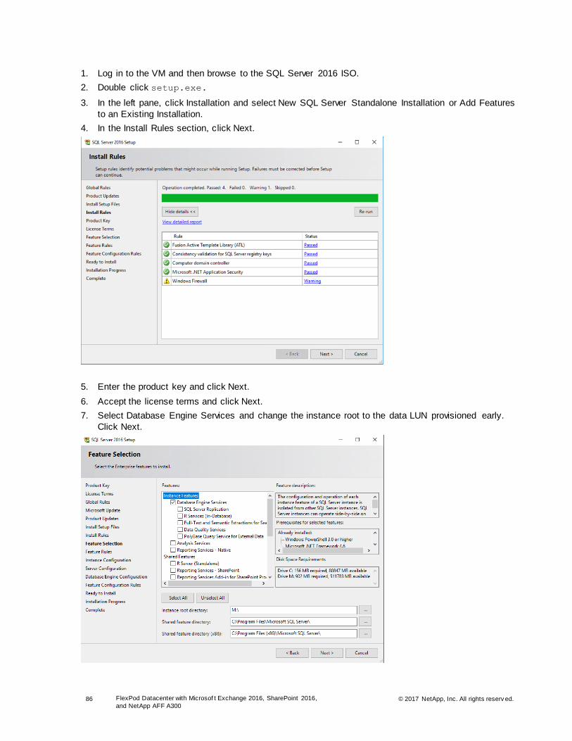
86 FlexPod Datacenter with Microsof t Exchange 2016, SharePoint 2016,
and NetApp AFF A300 © 2017 NetApp, Inc. All rights reserv ed.
1. Log in to the VM and then browse to the SQL Server 2016 ISO.
2. Double click setup.exe.
3. In the left pane, click Installation and select New SQL Server Standalone Installation or Add Features
to an Existing Installation.
4. In the Install Rules section, click Next.
5. Enter the product key and click Next.
6. Accept the license terms and click Next.
7. Select Database Engine Services and change the instance root to the data LUN provisioned early.
Click Next.

87 FlexPod Datacenter with Microsof t Exchange 2016, SharePoint 2016,
and NetApp AFF A300 © 2017 NetApp, Inc. All rights reserv ed.
8. Select Default Instance and click Next.
9. On the Server Configuration page, specify the SPSQL service account details and collation
configuration details and click Next.
10. On the Database Engine Configuration page, select the Windows authentication mode and add the
SQL administrators group and the SPInstall service account in the SQL Server administrators section.
11. From the Data Directories tab, make sure that the root directory and the database and log directories
are set appropriately to the LUNs created earlier.
12. The Feature Configuration Rules feature runs automatically. Verify the output and click Next.

88 FlexPod Datacenter with Microsof t Exchange 2016, SharePoint 2016,
and NetApp AFF A300 © 2017 NetApp, Inc. All rights reserv ed.
13. On the Ready to Install page, verify the installation options and click Install to begin the SQL Server
installation.
14. After the installation is complete, verify the installation summary and click Close to close the wizard.
15. Repeat steps 1 through 14 on the remaining SQL Server instances.
Configure SQL Service Dependency
In order to support the data operations, DocAve must perform with the SQL AG; therefore, NetApp
installed the SQL instance on a dedicated LUN. This step made sure that the instance-level files were not
on the same LUN as the SharePoint data. Unfortunately, this introduces a race condition where the iSCSI
LUNs must be mounted before the SQL service can start. To address this issue, the SQL service is made
dependent on the iSCSI service.
1. To make the SQL service dependent on the iSCSI service, run the following command from an
admin cmd prompt:
sc config MSSQLSERVER depend= MSiSCSI
Install SQL Management Studio
With SQL Server 2016, the management tools must be installed separately from the database engine.
Open the SQL Server Installation Center by double-clicking setup.exe on the SQL Server 2016 ISO
and then complete the following steps:
1. In the left pane, select Installation and then click Install SQL Server Management Tools.
2. From the Microsoft website, download and install the SQL Server Management Studio (SSMS)
executable file.
3. After the installation is complete, click Close.
Configure Windows Firewall on SQL VMs
To allow traffic on ports 1433, 1434, and 5022 on the SQL Server VMs, log in to each of the SQL Server
VMs and complete the following steps:
1. Open a PowerShell prompt and run the following commands to create the necessary Windows
firewall rules:
$splat = @{Action='allow';Direction='Inbound'}
New-NetFirewallRule -DisplayName “SQL Default Instance" –Protocol TCP –LocalPort 1433 @splat
New-NetFirewallRule -DisplayName “SQL Admin Connection” –Protocol TCP –LocalPort 1434 @splat
New-NetFirewallRule -DisplayName “SQL AG EndPoint” –Protocol TCP –LocalPort 5022 @splat
New-NetFirewallRule -DisplayName “SQL Server Browser Service” –Protocol UDP `
–LocalPort 1434 @splat
New-NetFirewallRule -DisplayName “SQL Server Browse Button Service” –Protocol UDP `
–LocalPort 1433 @splat
New-NetFirewallRule -DisplayName “DocAve Agent” –Protocol TCP –LocalPort 14004 @splat
Note: Although DocAve is not yet installed, the firewall rule is staged to ease configuration.
Configure Maximum Degree of Parallelism
The maximum degree of parallelism is a feature that enables you to use all of the available CPUs for
each of the queries. For SharePoint, set the max degree to one by completing the following steps on all
SQL Server instances:
1. Open Microsoft SQL Server Management Studio and connect to the SQL DB instance by using the
administrator account.
2. Right-click the instance and click Properties.
3. In the left pane, click Advanced.
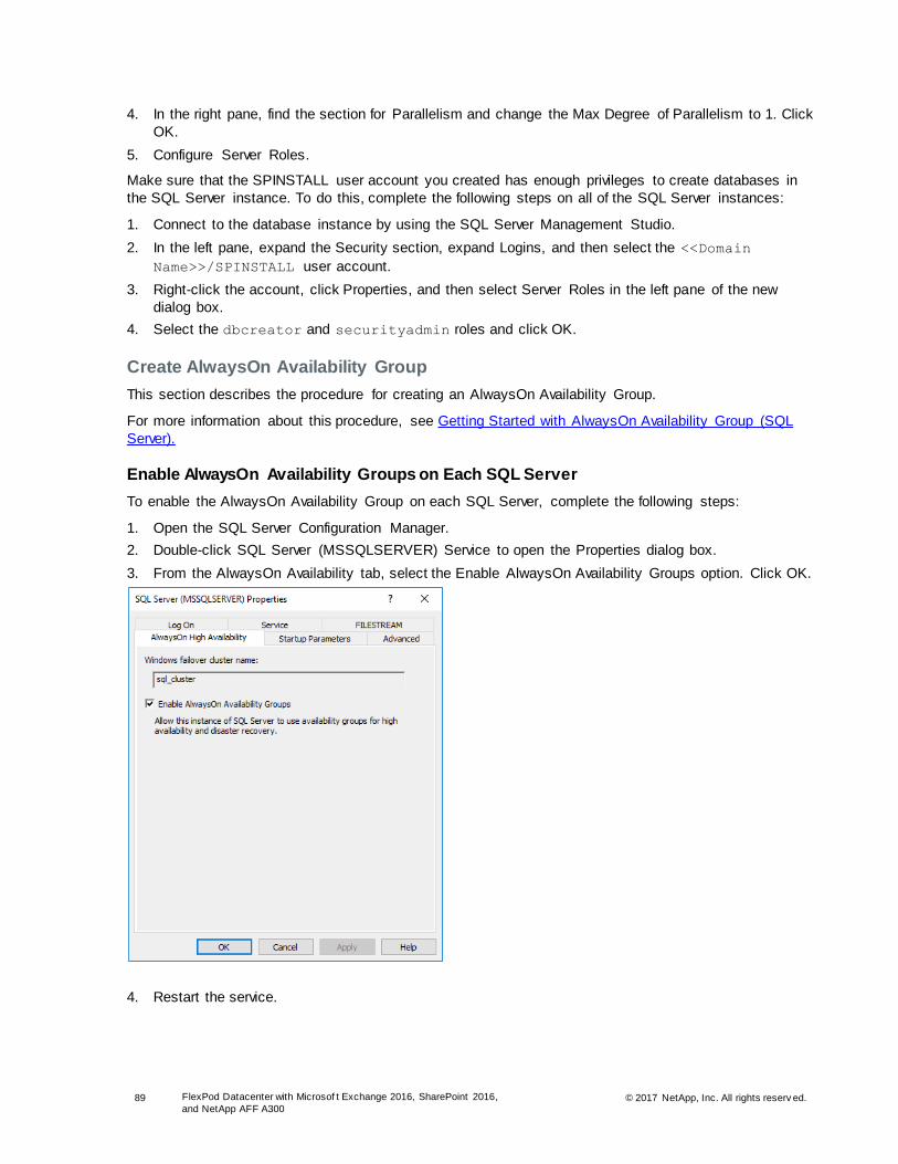
89 FlexPod Datacenter with Microsof t Exchange 2016, SharePoint 2016,
and NetApp AFF A300 © 2017 NetApp, Inc. All rights reserv ed.
4. In the right pane, find the section for Parallelism and change the Max Degree of Parallelism to 1. Click
OK.
5. Configure Server Roles.
Make sure that the SPINSTALL user account you created has enough privileges to create databases in
the SQL Server instance. To do this, complete the following steps on all of the SQL Server instances:
1. Connect to the database instance by using the SQL Server Management Studio.
2. In the left pane, expand the Security section, expand Logins, and then select the <<Domain
Name>>/SPINSTALL user account.
3. Right-click the account, click Properties, and then select Server Roles in the left pane of the new
dialog box.
4. Select the dbcreator and securityadmin roles and click OK.
Create AlwaysOn Availability Group
This section describes the procedure for creating an AlwaysOn Availability Group.
For more information about this procedure, see Getting Started with AlwaysOn Availability Group (SQL
Server).
Enable AlwaysOn Availability Groups on Each SQL Server
To enable the AlwaysOn Availability Group on each SQL Server, complete the following steps:
1. Open the SQL Server Configuration Manager.
2. Double-click SQL Server (MSSQLSERVER) Service to open the Properties dialog box.
3. From the AlwaysOn Availability tab, select the Enable AlwaysOn Availability Groups option. Click OK.
4. Restart the service.
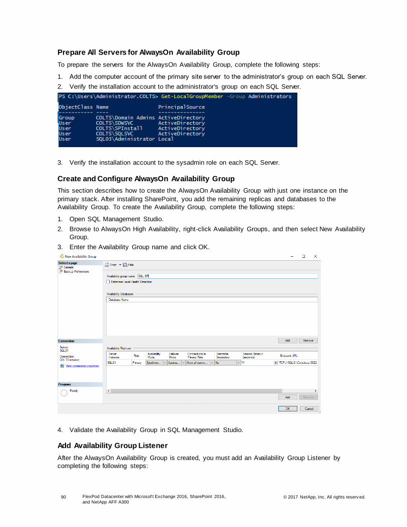
90 FlexPod Datacenter with Microsof t Exchange 2016, SharePoint 2016,
and NetApp AFF A300 © 2017 NetApp, Inc. All rights reserv ed.
Prepare All Servers for AlwaysOn Availability Group
To prepare the servers for the AlwaysOn Availability Group, complete the following steps:
1. Add the computer account of the primary site server to the administrator’s group on each SQL Server.
2. Verify the installation account to the administrator's group on each SQL Server.
3. Verify the installation account to the sysadmin role on each SQL Server.
Create and Configure AlwaysOn Availability Group
This section describes how to create the AlwaysOn Availability Group with just one instance on the
primary stack. After installing SharePoint, you add the remaining replicas and databases to the
Availability Group. To create the Availability Group, complete the following steps:
1. Open SQL Management Studio.
2. Browse to AlwaysOn High Availability, right-click Availability Groups, and then select New Availability
Group.
3. Enter the Availability Group name and click OK.
4. Validate the Availability Group in SQL Management Studio.
Add Availability Group Listener
After the AlwaysOn Availability Group is created, you must add an Availability Group Listener by
completing the following steps:

91 FlexPod Datacenter with Microsof t Exchange 2016, SharePoint 2016,
and NetApp AFF A300 © 2017 NetApp, Inc. All rights reserv ed.
1. Return to the SQL Server Management Studio.
2. Expand the Availability Group that you recently created. In the left pane, right-click the Availability
Group Listeners.
3. Enter a value in the Listener DNS Name field.
4. Enter the port number that you want to use. In this example, the default port is 1433.
5. Select Static IP from the Network Mode drop-down menu and then click Add to assign an IP address.
6. Add any additional subnets for the optional secondary sites.
7. After you enter the IP address, click OK.
8. Verify that the Availability Group Listener was created in the SQL Server Management Studio.
Configure Antiaffinity Rules for SQL VMs
To make sure that the entire SQL cluster does not go down when a single host in the vSphere
environment fails, you need to configure antiaffinity rules. By using antiaffinity rules, vSphere DRS tries to
keep the two SQL VMs apart, so that when a problem occurs with one host, you do not lose both SQL
VMs. To configure these antiaffinity rules, complete the following steps:
1. Log in to the vCenter Server.
2. Go to Hosts and Clusters view and then select the cluster.
3. In the right pane, click Configure.
4. Select VM/Host Rules.
5. Click Add.

92 FlexPod Datacenter with Microsof t Exchange 2016, SharePoint 2016,
and NetApp AFF A300 © 2017 NetApp, Inc. All rights reserv ed.
6. Specify a name for the rule and then select the Enable Rule option.
7. From the Type drop-down menu, select Separate Virtual Machines.
8. Click Add to add the two SQL VMs and click OK.
SnapManager for Microsoft SQL Server DocAve Manager, which you install later in this guide, is used to back up the SharePoint farm. However, for DocAve Manager to be able to perform the backup and recovery operations, SnapManager for
Microsoft SQL Server must be installed. This section describes the necessary steps to install and
configure SnapManager.
Install SnapManager for Microsoft SQL Server
To install SnapManager for Microsoft SQL Server, complete the following steps:
1. Run SMSQL7.2.2P2_x64.exe as administrator to start the InstallShield wizard for SnapManager for
Microsoft SQL Server.
2. Click Install to confirm the installation of the required C++ and SQL compatibility components and
launch the installation wizard.
3. Click Next to install the SnapManager for SQL Server in the InstallShield wizard.
4. Enter user name and organization information. On the Customer Information page, select the license
type and click Next.
5. (Optional) Change the SnapManager for SQL Installation folder. Click Next on the Destination Folder
page.
6. Enter the user account information and make sure that the account has the SQL Server sysadmin
role. Click Next.
Note: NetApp opted to reuse the SDW Service account, but larger organizations might select a dedicated account.
7. On the Ready to Install the Program page, click Install.
8. On the InstallShield Wizard Completed page, click Finish.
9. Repeat steps 1 through 8 for each node that is running a SQL Server instance.

93 FlexPod Datacenter with Microsof t Exchange 2016, SharePoint 2016,
and NetApp AFF A300 © 2017 NetApp, Inc. All rights reserv ed.
Configure SnapManager for Microsoft SQL Server
To configure SnapManager for SQL Server, complete the following steps:
1. Open SnapManager for Microsoft SQL Server.
2. Enter the SQL Server instance to be managed and then click Browse to select an instance. In the
Login Details area, select the Use Windows Authentication option and click Add.
Note: Make sure that the SDWSVC domain account that you created is added to the SQL Server with the sysadmin role.
3. The wizard detects that the selected server instance is not configured with SnapManager, and a
message displays prompting you to run the SnapManager Configuration wizard. Click OK.
4. Click Next to continue to the SnapManager configuration.
5. For database verification, select another SQL Server to run the database verification, select the Mount in an Empty NTFS Directory option, and then click Browse to specify the mount point directory.
Click Next.
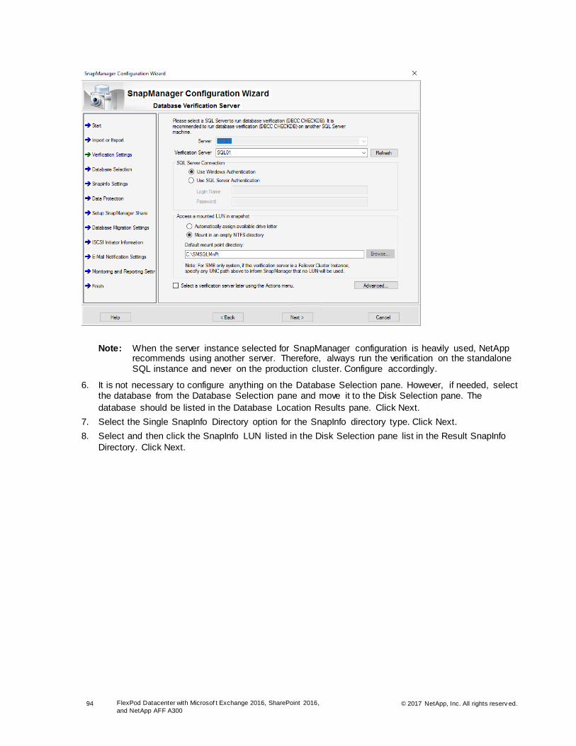
94 FlexPod Datacenter with Microsof t Exchange 2016, SharePoint 2016,
and NetApp AFF A300 © 2017 NetApp, Inc. All rights reserv ed.
Note: When the server instance selected for SnapManager configuration is heavily used, NetApp recommends using another server. Therefore, always run the verification on the standalone SQL instance and never on the production cluster. Configure accordingly.
6. It is not necessary to configure anything on the Database Selection pane. However, if needed, select the database from the Database Selection pane and move it to the Disk Selection pane. The
database should be listed in the Database Location Results pane. Click Next.
7. Select the Single SnapInfo Directory option for the SnapInfo directory type. Click Next.
8. Select and then click the SnapInfo LUN listed in the Disk Selection pane list in the Result SnapInfo
Directory. Click Next.

95 FlexPod Datacenter with Microsof t Exchange 2016, SharePoint 2016,
and NetApp AFF A300 © 2017 NetApp, Inc. All rights reserv ed.
9. Clear the Enable SnapManager Share option and then click Next.
Note: You can use the Configuration wizard to set a network location as a centralized location for copies of transaction logs. At the time logs are backed up, the backups are copied to this share. However, in this solution, NetApp opted to clear the Enable SnapManager share to save on redundant log storage.
10. For the database migration to be effective, the physical database integrity must be verified. To verify
the database integrity, select the options shown in the following figure and then click Next.

96 FlexPod Datacenter with Microsof t Exchange 2016, SharePoint 2016,
and NetApp AFF A300 © 2017 NetApp, Inc. All rights reserv ed.
11. On the Add Microsoft iSCSI Service Dependency page, select the iSCSI service as a dependency for the SQL Server instance. In a server cluster that uses only iSCSI service for the shared storage
device, you must make the cluster instance dependent on the Microsoft iSCSI initiator service. This is to make sure that the Microsoft iSCSI initiator service starts before the cluster instance starts. Adding
or removing service dependency restarts the SQL Server. Click Next.
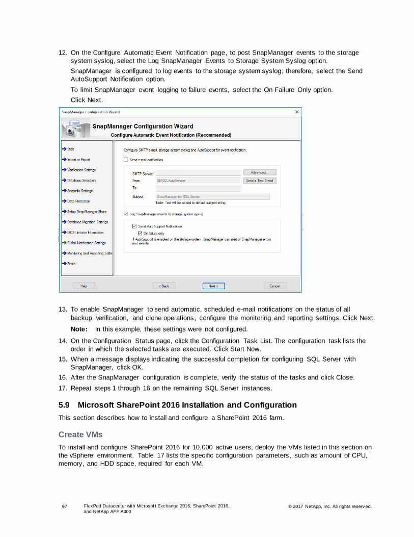
97 FlexPod Datacenter with Microsof t Exchange 2016, SharePoint 2016,
and NetApp AFF A300 © 2017 NetApp, Inc. All rights reserv ed.
12. On the Configure Automatic Event Notification page, to post SnapManager events to the storage
system syslog, select the Log SnapManager Events to Storage System Syslog option.
SnapManager is configured to log events to the storage system syslog; therefore, select the Send
AutoSupport Notification option.
To limit SnapManager event logging to failure events, select the On Failure Only option.
Click Next.
13. To enable SnapManager to send automatic, scheduled e-mail notifications on the status of all
backup, verification, and clone operations, configure the monitoring and reporting settings. Click Next.
Note: In this example, these settings were not configured.
14. On the Configuration Status page, click the Configuration Task List. The configuration task lists the
order in which the selected tasks are executed. Click Start Now.
15. When a message displays indicating the successful completion for configuring SQL Server with
SnapManager, click OK.
16. After the SnapManager configuration is complete, verify the status of the tasks and click Close.
17. Repeat steps 1 through 16 on the remaining SQL Server instances.
5.9 Microsoft SharePoint 2016 Installation and Configuration
This section describes how to install and configure a SharePoint 2016 farm.
Create VMs
To install and configure SharePoint 2016 for 10,000 active users, deploy the VMs listed in this section on
the vSphere environment. Table 17 lists the specific configuration parameters, such as amount of CPU,
memory, and HDD space, required for each VM.

98 FlexPod Datacenter with Microsof t Exchange 2016, SharePoint 2016,
and NetApp AFF A300 © 2017 NetApp, Inc. All rights reserv ed.
To deploy a highly scalable and reliable SharePoint farm, create multiple VMs for a particular SharePoint
role. Table 17 lists the VM configuration parameters for the SharePoint 2016 installation. Table 17 also
lists the number of VMs needed for each role.
Table 17) SharePoint 2016: VM configuration parameters.
Role Number of VMs RAM (GB) CPU HDD (GB)
Web front 6 16GB 4 80GB
Application 3 20GB 4 100GB
Distributed cache 1 16GB 4 80GB
Search 3 20GB 4 100GB
1. Create the VMs listed in Table 17 and attach a virtual network interface in the MGMT network port group. The virtual network interface should be a VMXNET 3 adapter. After you successfully create
the VMs, install Windows Server 2016 on each of them.
2. Bring up the VMs, install VMware Tools, assign the IP address and gateway in the MGMT subnet,
rename the host, and then join the machine to the AD domain.
3. Reboot each VM for it to successfully join the domain.
4. After the VM is back online, launch a PowerShell prompt by right-clicking the PowerShell icon in the
taskbar and then select Run as Administrator.
5. Enable remote management and remote desktop by using the SCONFIG application.
SCONFIG
6. Select Configure Remote Management.
7. Select Enable Remote Management.
8. Select Return to the Main Menu.
9. Select Remote Desktop.
10. Enter E to enable.
11. Enter 2 to allow any version of remote desktop. You are returned to the main menu.
12. Select Exit to Command Line.
13. Install all Windows updates on the VM.
Configure iSCSI and Install SnapDrive
After you deploy the VMs required to run the SharePoint farm, configure iSCSI and install SnapDrive only
on the three search VMs. This is a prerequisite step needed for the DocAve Manager installation and
configuration. To configure iSCSI and install SnapDrive for Windows on the search VMs, complete the
following steps on each search VM:
1. Add the multipath-IO features by running the following command:
Add-WindowsFeature NET-Framework-Core, Multipath-IO -IncludeManagementTools -Restart -Source
D:\Sources\Sxs
Note: SnapDrive for Windows requires .Net 3.5.
2. Configure local administrator access.
# SnapDrive service account
Add-LocalGroupMember -Group Administrators -Member Colts\SDWSVC
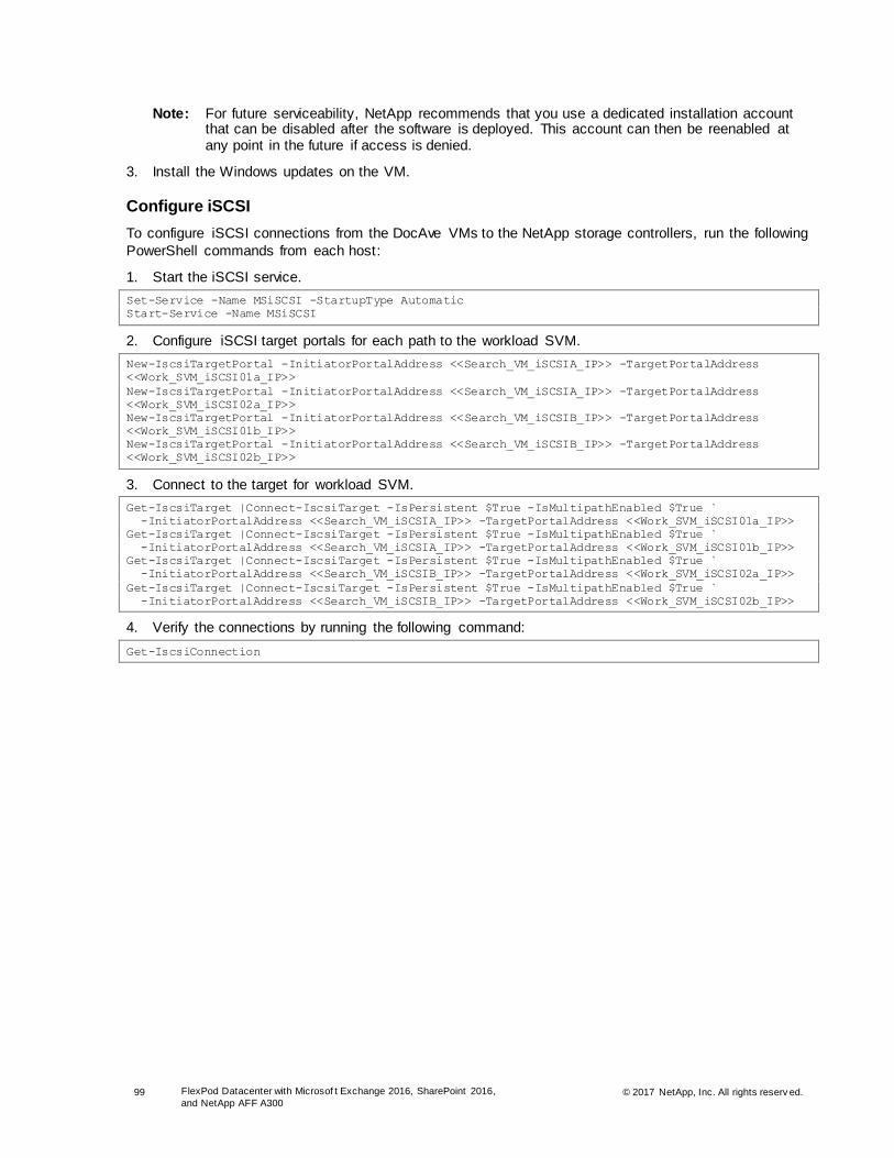
99 FlexPod Datacenter with Microsof t Exchange 2016, SharePoint 2016,
and NetApp AFF A300 © 2017 NetApp, Inc. All rights reserv ed.
Note: For future serviceability, NetApp recommends that you use a dedicated installation account that can be disabled after the software is deployed. This account can then be reenabled at any point in the future if access is denied.
3. Install the Windows updates on the VM.
Configure iSCSI
To configure iSCSI connections from the DocAve VMs to the NetApp storage controllers, run the following
PowerShell commands from each host:
1. Start the iSCSI service.
Set-Service -Name MSiSCSI -StartupType Automatic
Start-Service -Name MSiSCSI
2. Configure iSCSI target portals for each path to the workload SVM.
New-IscsiTargetPortal -InitiatorPortalAddress <<Search_VM_iSCSIA_IP>> -TargetPortalAddress
<<Work_SVM_iSCSI01a_IP>>
New-IscsiTargetPortal -InitiatorPortalAddress <<Search_VM_iSCSIA_IP>> -TargetPortalAddress
<<Work_SVM_iSCSI02a_IP>>
New-IscsiTargetPortal -InitiatorPortalAddress <<Search_VM_iSCSIB_IP>> -TargetPortalAddress
<<Work_SVM_iSCSI01b_IP>>
New-IscsiTargetPortal -InitiatorPortalAddress <<Search_VM_iSCSIB_IP>> -TargetPortalAddress
<<Work_SVM_iSCSI02b_IP>>
3. Connect to the target for workload SVM.
Get-IscsiTarget |Connect-IscsiTarget -IsPersistent $True -IsMultipathEnabled $True `
-InitiatorPortalAddress <<Search_VM_iSCSIA_IP>> -TargetPortalAddress <<Work_SVM_iSCSI01a_IP>>
Get-IscsiTarget |Connect-IscsiTarget -IsPersistent $True -IsMultipathEnabled $True `
-InitiatorPortalAddress <<Search_VM_iSCSIA_IP>> -TargetPortalAddress <<Work_SVM_iSCSI01b_IP>>
Get-IscsiTarget |Connect-IscsiTarget -IsPersistent $True -IsMultipathEnabled $True `
-InitiatorPortalAddress <<Search_VM_iSCSIB_IP>> -TargetPortalAddress <<Work_SVM_iSCSI02a_IP>>
Get-IscsiTarget |Connect-IscsiTarget -IsPersistent $True -IsMultipathEnabled $True `
-InitiatorPortalAddress <<Search_VM_iSCSIB_IP>> -TargetPortalAddress <<Work_SVM_iSCSI02b_IP>>
4. Verify the connections by running the following command:
Get-IscsiConnection
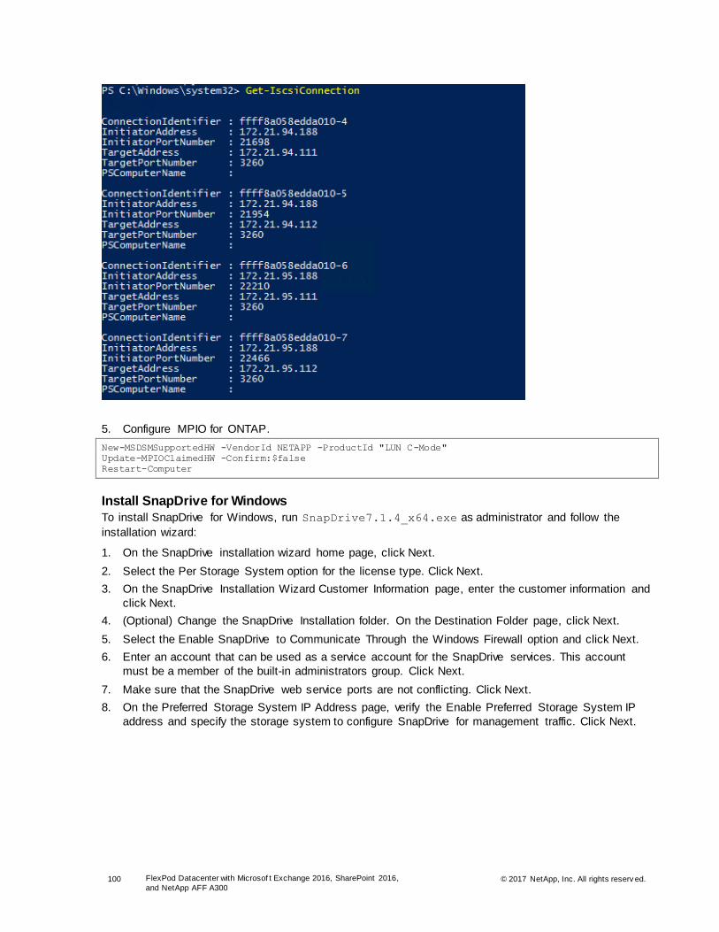
100 FlexPod Datacenter with Microsof t Exchange 2016, SharePoint 2016,
and NetApp AFF A300 © 2017 NetApp, Inc. All rights reserv ed.
5. Configure MPIO for ONTAP.
New-MSDSMSupportedHW -VendorId NETAPP -ProductId "LUN C-Mode"
Update-MPIOClaimedHW -Confirm:$false
Restart-Computer
Install SnapDrive for Windows
To install SnapDrive for Windows, run SnapDrive7.1.4_x64.exe as administrator and follow the
installation wizard:
1. On the SnapDrive installation wizard home page, click Next.
2. Select the Per Storage System option for the license type. Click Next.
3. On the SnapDrive Installation Wizard Customer Information page, enter the customer information and
click Next.
4. (Optional) Change the SnapDrive Installation folder. On the Destination Folder page, click Next.
5. Select the Enable SnapDrive to Communicate Through the Windows Firewall option and click Next.
6. Enter an account that can be used as a service account for the SnapDrive services. This account
must be a member of the built-in administrators group. Click Next.
7. Make sure that the SnapDrive web service ports are not conflicting. Click Next.
8. On the Preferred Storage System IP Address page, verify the Enable Preferred Storage System IP
address and specify the storage system to configure SnapDrive for management traffic. Click Next.

101 FlexPod Datacenter with Microsof t Exchange 2016, SharePoint 2016,
and NetApp AFF A300 © 2017 NetApp, Inc. All rights reserv ed.
9. On the Transport Protocol Default Setting page, select the Enable the Transport Protocol Settings
option. By enabling the transport protocol, you can talk to the storage system.
Select the HTTPS option. This requires you to enter a user name, password, and port ID. Click Next.
10. On the Unified Manager Configuration page, click Next.
11. Click Install to begin the SnapDrive installation.
Create Index LUNs for Search Servers
To create index LUNs for the search servers, complete the following steps:

102 FlexPod Datacenter with Microsof t Exchange 2016, SharePoint 2016,
and NetApp AFF A300 © 2017 NetApp, Inc. All rights reserv ed.
1. SSH into the cluster management interface for the storage system and then run the following
commands to create a new volume for index LUNs:
volume create -vserver Work-SVM -volume Search_Index -aggregate n01_ssd01 -size 500GB -state
online -policy default -space-guarantee none -percent-snapshot-space 0
snapmirror update-ls-set -source-path Work-SVM:rootvol
2. NetApp recommends using SnapDrive for Windows to create the LUNs. There are two methods available to create the LUNs: either use the SDW GUI or use the SDCLI. The following examples are
for using the SDCLI method.
sdcli disk create -dtype dedicated -m SearchXX -D L:\ -p Work-SVM:/vol/Search_Index/IndexXX.lun -
I initiatorname -z 100GB
a. Use the following environment variables for the SDCLI:
-m: machine name
-D: mount point location
-p: path to the volume where the LUN is created
-I: initiator name
-z: LUN size
b. Change the variables to meet the requirements of your environment.
c. After the L:\ drive is mounted, create a new directory called Index in the L:\ drive.
Install SharePoint 2016 Prerequisites
The VMs are ready to use. Before you install SharePoint 2016, you need to install the SharePoint
prerequisites.
1. Establish a remote desktop session with each VM.
2. Add the SPINSTALL user to the local administrators group on all the SharePoint VMs.
3. Log in to the VMs by using the SPINSTALL user account.
4. Mount the SharePoint 2016 ISO to the VM and then browse to it.
5. Find the prerequisiteinstaller.exe and double-click it.
6. Click Next.
7. Review and accept the license agreement and click Next.
8. After a few minutes, you see a screen that asks you to restart your system to continue with the
installation. Click Finish.
9. After the VM is back, mount the ISO again and start the prerequisite installer again.
10. Review and accept the license agreement and click Next.
11. When the installation is complete, click Finish.

103 FlexPod Datacenter with Microsof t Exchange 2016, SharePoint 2016,
and NetApp AFF A300 © 2017 NetApp, Inc. All rights reserv ed.
12. Repeat steps 1 through 11 on all the SharePoint VMs.
Install SharePoint 2016
Now that the prerequisites are installed, install SharePoint on all the VMs by completing the following
steps:
1. Log in to the SharePoint VM by using the SPINSTALL user account.
2. Mount the SharePoint 2016 ISO to the VM and then browse to it.
3. Double-click the splash.html file.
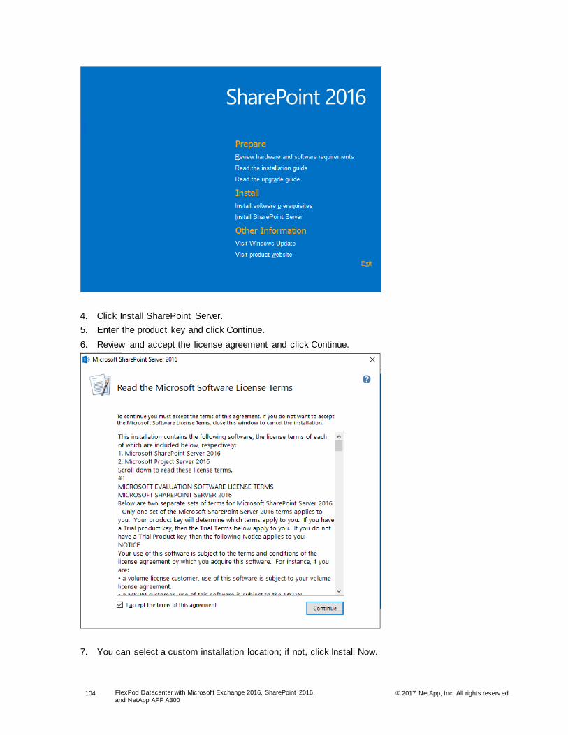
104 FlexPod Datacenter with Microsof t Exchange 2016, SharePoint 2016,
and NetApp AFF A300 © 2017 NetApp, Inc. All rights reserv ed.
4. Click Install SharePoint Server.
5. Enter the product key and click Continue.
6. Review and accept the license agreement and click Continue.
7. You can select a custom installation location; if not, click Install Now.

105 FlexPod Datacenter with Microsof t Exchange 2016, SharePoint 2016,
and NetApp AFF A300 © 2017 NetApp, Inc. All rights reserv ed.
8. After the installation is complete, make sure that the Run the SharePoint Products Configuration
Wizard Now option is selected. Do not click Close now.
9. Log in to the other SharePoint VMs and repeat steps 1 through 8.
10. After SharePoint is installed on all of the VMs, go back to the first application server VM and click
Close to launch the Products Configuration wizard.
Create SharePoint 2016 Farm
After you click Close on the Application Server VM, the SharePoint Products Configuration wizard starts.
To configure the specific role on each VM, complete the following steps:
1. Click Next and then click Yes.
2. Select the Create a New Server Farm option. Click Next.

106 FlexPod Datacenter with Microsof t Exchange 2016, SharePoint 2016,
and NetApp AFF A300 © 2017 NetApp, Inc. All rights reserv ed.
3. Enter the availability group listener information and the <<Domain Name>>\SPFARM credentials.
Click Next.
4. Select and enter a passphrase, which is used by other servers to join the server farm.
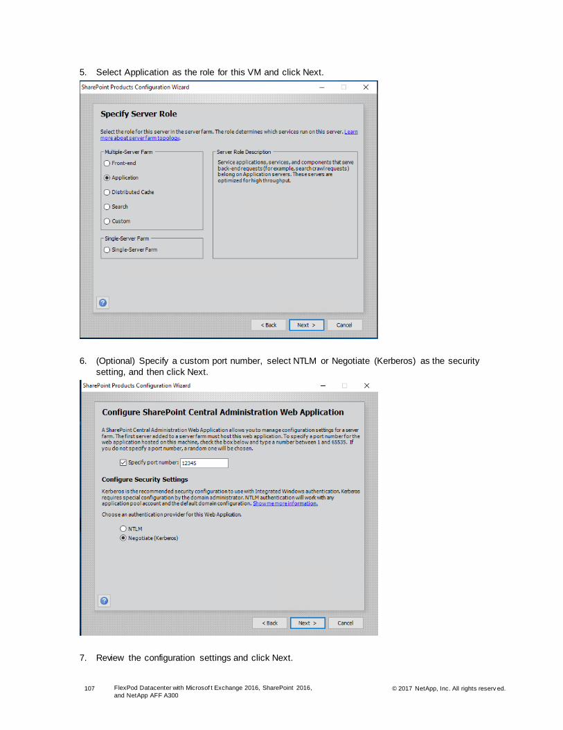
107 FlexPod Datacenter with Microsof t Exchange 2016, SharePoint 2016,
and NetApp AFF A300 © 2017 NetApp, Inc. All rights reserv ed.
5. Select Application as the role for this VM and click Next.
6. (Optional) Specify a custom port number, select NTLM or Negotiate (Kerberos) as the security
setting, and then click Next.
7. Review the configuration settings and click Next.

108 FlexPod Datacenter with Microsof t Exchange 2016, SharePoint 2016,
and NetApp AFF A300 © 2017 NetApp, Inc. All rights reserv ed.
8. After the configuration settings are successfully applied, capture the central administration URL
address and click Finish.
Add Servers to SharePoint 2016 Farm
After the SharePoint 2016 farm is created on the first application server, go back to the other VMs that
you created and join them to the farm and install specific roles. Complete the following steps on all the
SharePoint VMs to have a fully populated SharePoint farm:
1. Log in to all of the remaining SharePoint VMs by using the SPINSTALL account.
2. Click Close on the SharePoint Installation wizard to open the SharePoint Products Configuration
wizard.
3. Click Next and then click Yes.
4. Select the Connect to an Existing Server Farm option and click Next.
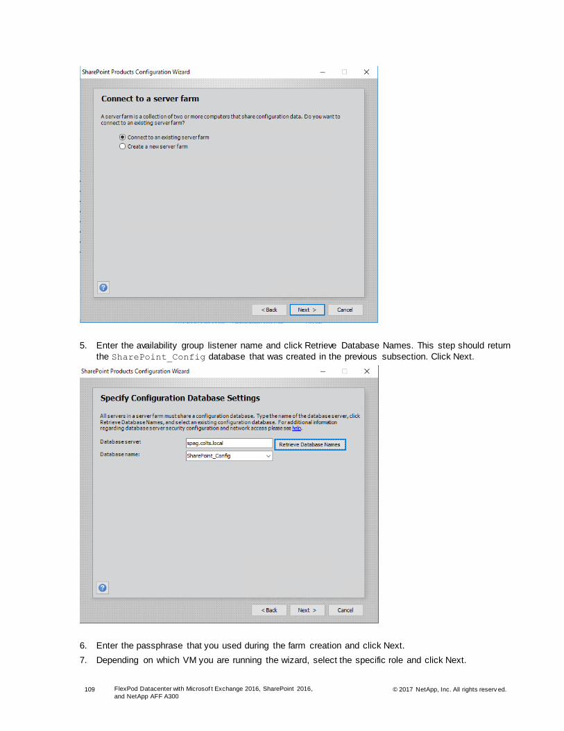
109 FlexPod Datacenter with Microsof t Exchange 2016, SharePoint 2016,
and NetApp AFF A300 © 2017 NetApp, Inc. All rights reserv ed.
5. Enter the availability group listener name and click Retrieve Database Names. This step should return
the SharePoint_Config database that was created in the previous subsection. Click Next.
6. Enter the passphrase that you used during the farm creation and click Next.
7. Depending on which VM you are running the wizard, select the specific role and click Next.
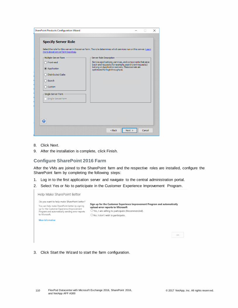
110 FlexPod Datacenter with Microsof t Exchange 2016, SharePoint 2016,
and NetApp AFF A300 © 2017 NetApp, Inc. All rights reserv ed.
8. Click Next.
9. After the installation is complete, click Finish.
Configure SharePoint 2016 Farm
After the VMs are joined to the SharePoint farm and the respective roles are installed, configure the
SharePoint farm by completing the following steps:
1. Log in to the first application server and navigate to the central administration portal.
2. Select Yes or No to participate in the Customer Experience Improvement Program.
3. Click Start the Wizard to start the farm configuration.

111 FlexPod Datacenter with Microsof t Exchange 2016, SharePoint 2016,
and NetApp AFF A300 © 2017 NetApp, Inc. All rights reserv ed.
4. Select the Use Existing Managed Account option to use the SPFARM account to configure the farm.
5. Select the service applications and services that you want to include in this farm and click Next.
6. Create a site collection and click OK.
7. Click Finish.
8. Log in to the remaining VMs and browse to the Central Administration page.
9. Click Start the Wizard.
10. The farm is already on the first host, so you should get an immediate response. Click Finish.
Configure Index Component for SharePoint Search Servers
After the farm is configured, configure the index location by running the following script on each of the
search servers:
1. Open the SharePoint management shell as an administrator and run the following script:
#Get Search Service Instance and Start on New Index Server
$ssi = Get-SPEnterpriseSearchServiceInstance -Identity $env:COMPUTERNAME
Start-SPEnterpriseSearchServiceInstance -Identity $ssi
#Wait for Search Service Instance to come online
do {$online = Get-SPEnterpriseSearchServiceInstance -Identity $ssi; Write-Host "Waiting for
service: " $online.Status}
until ($online.Status -eq "Online")
#Clone Active Search Topology

112 FlexPod Datacenter with Microsof t Exchange 2016, SharePoint 2016,
and NetApp AFF A300 © 2017 NetApp, Inc. All rights reserv ed.
$ssa = Get-SPEnterpriseSearchServiceApplication
$active = Get-SPEnterpriseSearchTopology -SearchApplication $ssa -Active
$clone = New-SPEnterpriseSearchTopology -SearchApplication $ssa -Clone –SearchTopology $active
#Create New Index Component for Index Partition 0
$sic = New-SPEnterpriseSearchIndexComponent –SearchTopology $clone -SearchServiceInstance $ssi -
IndexPartition 0 -RootDirectory "L:\Index"
#Activate the Cloned Search Topology
Set-SPEnterpriseSearchTopology -Identity $clone
#Review new topology
Get-SPEnterpriseSearchTopology -Active -SearchApplication $ssa
#Monitor Distribution of Index
do {$activeState = Get-SPEnterpriseSearchStatus -SearchApplication $ssa |
Where-Object {$_.Name -eq $sic.Name}; Write-Host "Waiting for active distribution: "
$activeState.State}
until ($activeState.State -eq "Active")
Add Replicas and SharePoint Databases to AlwaysOn Availability Group
After SharePoint 2016 is successfully installed, add replicas and all the databases to the AlwaysOn
Availability Group that you created in the section titled “SQL Server Installation” by completing the
following steps:
1. Connect to the SQL instance on the primary stack where you created the Availability Group.
2. In the left pane, expand the Availability Group.
3. Right-click the availability replicas and click Add Replicas. Click Next.
4. Connect to the remaining two SQL instances: Set Synchronous Commit, Automatic Failover, and Readable Secondary for the instance running on the primary stack and select Asynchronous Commit,
Manual Failover, and No Readable Secondary for the instance on the secondary stack.

113 FlexPod Datacenter with Microsof t Exchange 2016, SharePoint 2016,
and NetApp AFF A300 © 2017 NetApp, Inc. All rights reserv ed.
Note: If the Next button is grayed out, then run the following query against SQL01 to enable the HADR endpoint.
create endpoint [Hadr_endpoint]
state=started
as tcp (listener_port = 5022, listener_ip = all)
for database_mirroring (role = all, authentication = windows negotiate, encryption = required
algorithm aes)
go
5. Click Next.
6. Enter a shared network location and then click Next.

114 FlexPod Datacenter with Microsof t Exchange 2016, SharePoint 2016,
and NetApp AFF A300 © 2017 NetApp, Inc. All rights reserv ed.
7. Click Next.
8. After the rules are passed, click Next.
9. Click Finish and then close the wizard after it successfully completes.
10. After the replicas are added, right-click the availability databases under the Availability Groups and
click Add Database.
11. Click Next.
12. Select all of the SharePoint databases and click Next.
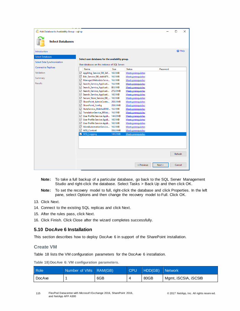
115 FlexPod Datacenter with Microsof t Exchange 2016, SharePoint 2016,
and NetApp AFF A300 © 2017 NetApp, Inc. All rights reserv ed.
Note: To take a full backup of a particular database, go back to the SQL Server Management Studio and right-click the database. Select Tasks > Back Up and then click OK.
Note: To set the recovery model to full, right-click the database and click Properties. In the left pane, select Options and then change the recovery model to Full. Click OK.
13. Click Next.
14. Connect to the existing SQL replicas and click Next.
15. After the rules pass, click Next.
16. Click Finish. Click Close after the wizard completes successfully.
5.10 DocAve 6 Installation
This section describes how to deploy DocAve 6 in support of the SharePoint installation.
Create VM
Table 18 lists the VM configuration parameters for the DocAve 6 installation.
Table 18) DocAve 6: VM configuration parameters.
Role Number of VMs RAM(GB) CPU HDD(GB) Network
DocAve 1 6GB 4 80GB Mgmt, iSCSIA, iSCSIB
116 FlexPod Datacenter with Microsof t Exchange 2016, SharePoint 2016,
and NetApp AFF A300 © 2017 NetApp, Inc. All rights reserv ed.
To create VMs for use in the DocAve 6 installation, complete the following steps:
1. Provision Windows Server 2016 with at least 6GB of RAM, four vCPUs, 80GB HDD, and virtual network interfaces in the MGMT network, iSCSIA, and iSCSIB port groups. The virtual network
interfaces should be VMXNET 3 adapters.
2. Install VMware Tools, assign the IP address and gateway in the MGMT subnet, and join the machine
to the AD domain.
3. Launch a PowerShell prompt by right-clicking the PowerShell icon in the taskbar and selecting Run
as Administrator.
4. Enable remote management and remote desktop by using the SCONFIG application.
SCONFIG
5. Select Configure Remote Management.
6. Select Enable Remote Management.
7. Select Return to the Main Menu.
8. Select Remote Desktop.
9. Enter E to enable.
10. Enter 2 to allow any version of remote desktop. After this step, you are returned to the main menu.
11. Select Exit to Command Line.
12. Add the Windows failover clustering and multipath I/O features by running the following command:
Add-WindowsFeature NET-Framework-Core, Multipath-IO -IncludeManagementTools -Restart -Source
D:\Sources\Sxs
Note: SnapDrive for Windows requires .Net 3.5.
13. Configure local administrator access.
# SnapDrive service account
Add-LocalGroupMember -Group Administrators -Member Colts\SDWSVC
#Dedicated installation account
Add-LocalGroupMember -Group Administrators -Member Colts\SPInstall
Note: For future serviceability, NetApp recommends that you use a dedicated installation account that can be disabled after the software is deployed. This account can then be reenabled at any point in the future if access is denied.
14. Install the Windows updates on the VM.
Configure iSCSI
To configure iSCSI connections from the DocAve VMs to the NetApp storage controllers, run the following
PowerShell commands from each host:
1. Start the iSCSI service.
Set-Service -Name MSiSCSI -StartupType Automatic
Start-Service -Name MSiSCSI
2. Configure iSCSI target portals for each path to the SharePoint SVM.
New-IscsiTargetPortal -InitiatorPortalAddress <<DocAve_VM_iSCSIA_IP>> -TargetPortalAddress
<<SharePoint_SVM_iSCSI01a_IP>>
New-IscsiTargetPortal -InitiatorPortalAddress <<DocAve_VM_iSCSIA_IP>> -TargetPortalAddress
<<SharePoint_SVM_iSCSI02a_IP>>
New-IscsiTargetPortal -InitiatorPortalAddress <<DocAve_VM_iSCSIB_IP>> -TargetPortalAddress
<<SharePoint_SVM_iSCSI01b_IP>>
New-IscsiTargetPortal -InitiatorPortalAddress <<DocAve_VM_iSCSIB_IP>> -TargetPortalAddress
<<SharePoint_SVM_iSCSI02b_IP>>
3. Connect to the target for SharePoint SVM.
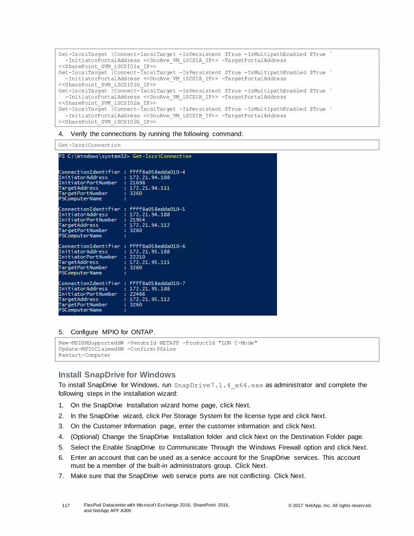
117 FlexPod Datacenter with Microsof t Exchange 2016, SharePoint 2016,
and NetApp AFF A300 © 2017 NetApp, Inc. All rights reserv ed.
Get-IscsiTarget |Connect-IscsiTarget -IsPersistent $True -IsMultipathEnabled $True `
-InitiatorPortalAddress <<DocAve_VM_iSCSIA_IP>> -TargetPortalAddress
<<SharePoint_SVM_iSCSI01a_IP>>
Get-IscsiTarget |Connect-IscsiTarget -IsPersistent $True -IsMultipathEnabled $True `
-InitiatorPortalAddress <<DocAve_VM_iSCSIA_IP>> -TargetPortalAddress
<<SharePoint_SVM_iSCSI01b_IP>>
Get-IscsiTarget |Connect-IscsiTarget -IsPersistent $True -IsMultipathEnabled $True `
-InitiatorPortalAddress <<DocAve_VM_iSCSIB_IP>> -TargetPortalAddress
<<SharePoint_SVM_iSCSI02a_IP>>
Get-IscsiTarget |Connect-IscsiTarget -IsPersistent $True -IsMultipathEnabled $True `
-InitiatorPortalAddress <<DocAve_VM_iSCSIB_IP>> -TargetPortalAddress
<<SharePoint_SVM_iSCSI02b_IP>>
4. Verify the connections by running the following command:
Get-IscsiConnection
5. Configure MPIO for ONTAP.
New-MSDSMSupportedHW -VendorId NETAPP -ProductId "LUN C-Mode"
Update-MPIOClaimedHW -Confirm:$false
Restart-Computer
Install SnapDrive for Windows
To install SnapDrive for Windows, run SnapDrive7.1.4_x64.exe as administrator and complete the
following steps in the installation wizard:
1. On the SnapDrive Installation wizard home page, click Next.
2. In the SnapDrive wizard, click Per Storage System for the license type and click Next.
3. On the Customer Information page, enter the customer information and click Next.
4. (Optional) Change the SnapDrive Installation folder and click Next on the Destination Folder page.
5. Select the Enable SnapDrive to Communicate Through the Windows Firewall option and click Next.
6. Enter an account that can be used as a service account for the SnapDrive services. This account
must be a member of the built-in administrators group. Click Next.
7. Make sure that the SnapDrive web service ports are not conflicting. Click Next.

118 FlexPod Datacenter with Microsof t Exchange 2016, SharePoint 2016,
and NetApp AFF A300 © 2017 NetApp, Inc. All rights reserv ed.
8. On the Preferred Storage System IP Address page, select the Enable Preferred Storage System IP Address option. Specify the storage system to configure SnapDrive for management traffic. Click
Next.
9. Select the Enable the Transport Protocol Settings option. By enabling the transport protocol, you can
talk to the storage system.
Select the HTTPS option. This requires you to enter a user name, password, and port ID. Click Next.
10. Click Next in the Unified Manager Configuration.
11. Click Install to begin the SnapDrive installation.

119 FlexPod Datacenter with Microsof t Exchange 2016, SharePoint 2016,
and NetApp AFF A300 © 2017 NetApp, Inc. All rights reserv ed.
Mount Storage
In the previous subsection, you configured the iSCSI connections and installed SnapDrive on both
DocAve VMs. In this section, create and mount all of the external storage.
Table 19) SQL primary site storage.
Server Volume Mount Point LUN Size
DocAve01 DocAve1_Media M:\ 1TB
Note: NetApp recommends using SnapDrive for Windows to create the LUNs to house the databases and logs for your SQL Server instances. There are two methods available to create the LUNs: use the SDW GUI or the SDCLI. The following examples use the SDCLI method.
1. Create a DocAve media LUN.
sdcli disk create -dtype dedicated -m DocAve01 -D M:\ -p Work-
SVM.colts.local:/vol/DocAve1_Media/Media.lun -I DocAve01 iqn.1991-
05.com.microsoft:DocAve01.colts.local -z 1TB
2. Make sure that the LUNs have all been created and mounted to the appropriate path by running the
following SnapDrive PowerShell command:
Get-SdStorage
Install Prerequisites for DocAve Manager
To install the prerequisites for DocAve Manager, complete the following step:
1. Install the required IIS components by running the following command:
Install-WindowsFeature Web-Common-Http,Web-Default-Doc, Web-Static-Content, Web-App-Dev, Web-
Asp-Net, Web-Net-Ext, Web-ISAPI-Ext, Web-ISAPI-Filter, Web-Mgmt-Console, Web-Mgmt-Compat, Web-
Metabase, NET-HTTP-Activation, NET-Non-HTTP-Activ
Note: Make sure that the Windows Process Activation Service and World Wide Web Publishing Service are running.
Install DocAve Manager
To install the DocAve Manager, complete the following steps:
1. Unzip the DocAve_v6_Manager folder and double-click the setup.exe file.
2. Click Next.
3. On the Customer Information page, enter your name and organization in the designated fields. Click
Next.
4. Review and accept the DocAve license agreement. Click Next.
Note: After the DocAve Manager installation completes, you can navigate to the manager installation path …\Manager\lic\ to see your demo licenses.
5. Select the installation location and click Next.
6. On the Service Installation page, select the Complete installation method and click Next.
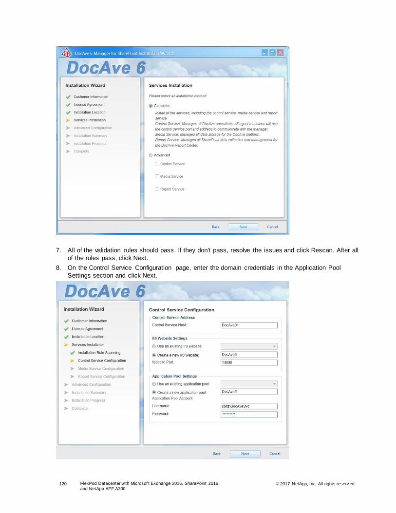
120 FlexPod Datacenter with Microsof t Exchange 2016, SharePoint 2016,
and NetApp AFF A300 © 2017 NetApp, Inc. All rights reserv ed.
7. All of the validation rules should pass. If they don't pass, resolve the issues and click Rescan. After all
of the rules pass, click Next.
8. On the Control Service Configuration page, enter the domain credentials in the Application Pool
Settings section and click Next.
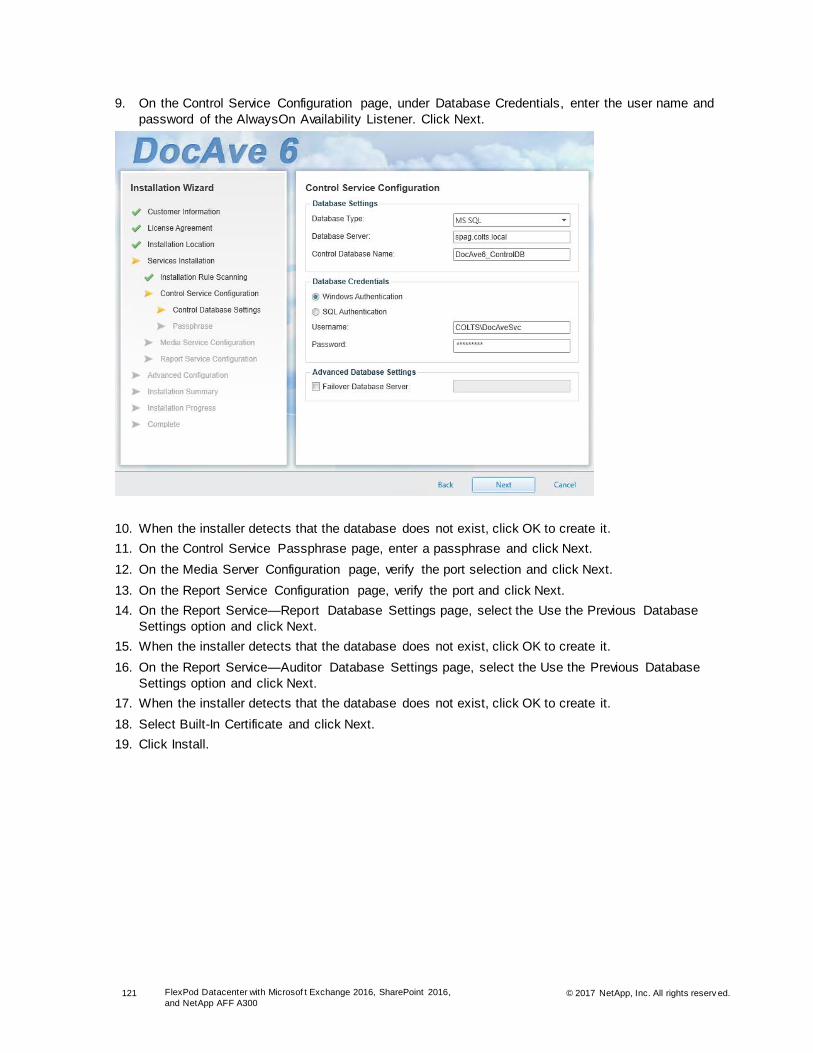
121 FlexPod Datacenter with Microsof t Exchange 2016, SharePoint 2016,
and NetApp AFF A300 © 2017 NetApp, Inc. All rights reserv ed.
9. On the Control Service Configuration page, under Database Credentials, enter the user name and
password of the AlwaysOn Availability Listener. Click Next.
10. When the installer detects that the database does not exist, click OK to create it.
11. On the Control Service Passphrase page, enter a passphrase and click Next.
12. On the Media Server Configuration page, verify the port selection and click Next.
13. On the Report Service Configuration page, verify the port and click Next.
14. On the Report Service—Report Database Settings page, select the Use the Previous Database
Settings option and click Next.
15. When the installer detects that the database does not exist, click OK to create it.
16. On the Report Service—Auditor Database Settings page, select the Use the Previous Database
Settings option and click Next.
17. When the installer detects that the database does not exist, click OK to create it.
18. Select Built-In Certificate and click Next.
19. Click Install.
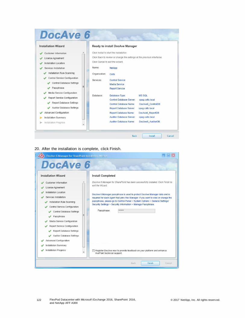
122 FlexPod Datacenter with Microsof t Exchange 2016, SharePoint 2016,
and NetApp AFF A300 © 2017 NetApp, Inc. All rights reserv ed.
20. After the installation is complete, click Finish.

123 FlexPod Datacenter with Microsof t Exchange 2016, SharePoint 2016,
and NetApp AFF A300 © 2017 NetApp, Inc. All rights reserv ed.
Install DocAve Agent
The DocAve Agent must be installed on every server participating in the farm (DocAve Media, SQL, front-
end, search, application, and cache servers) by completing the following steps:
1. Before installing the DocAve Agent, add the DocAveSvc account to the local administrators group.
Add-LocalGroupMember -Group Administrators -Member Colts\DocAveSvc
2. Run the DocAve_v6_Agent setup file to start the SMSP Agent Installation wizard.
3. Click Next.
4. Enter the name and organization and click Next.
5. Review and accept the license agreement and click Next.
6. Select the installation location and click Next.
7. After the installation rules have passed, click Next.
8. Enter the host name of the DocAve control service host and click Next.
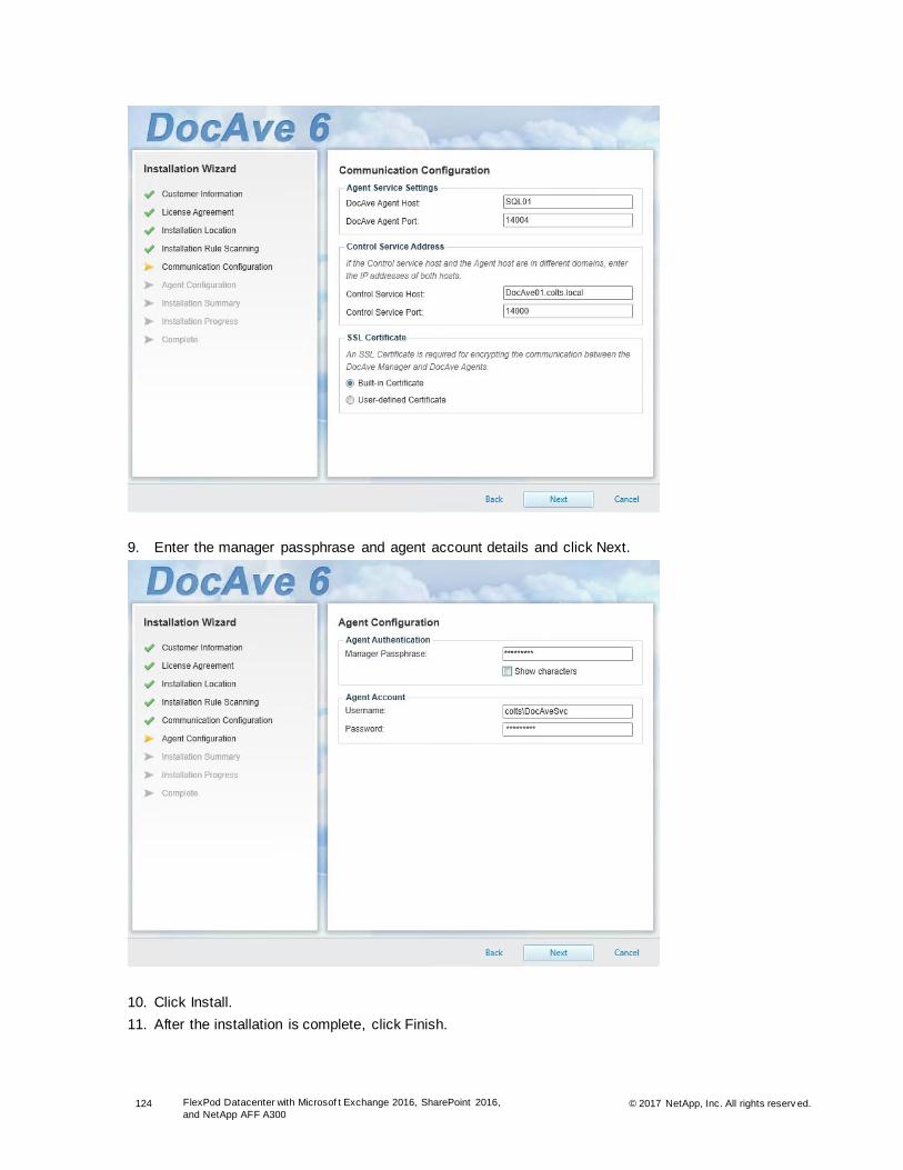
124 FlexPod Datacenter with Microsof t Exchange 2016, SharePoint 2016,
and NetApp AFF A300 © 2017 NetApp, Inc. All rights reserv ed.
9. Enter the manager passphrase and agent account details and click Next.
10. Click Install.
11. After the installation is complete, click Finish.

125 FlexPod Datacenter with Microsof t Exchange 2016, SharePoint 2016,
and NetApp AFF A300 © 2017 NetApp, Inc. All rights reserv ed.
12. Repeat steps 1 through 11 to install the DocAve Agent on all of the SharePoint servers (front-end,
application, search, and cache) and on all of the SQL Server instances.
Note: If you did not do so earlier, add the inbound rule to the SQL Server VM firewalls to allow the DocAve Agent port.
$splat = @{Action='allow';Direction='Inbound'}
New-NetFirewallRule -DisplayName “DocAve Agent” –Protocol TCP –LocalPort 14004 @splat
Configure DocAve Manager
To configure DocAve Manager, complete the following steps:
1. Open the SMSP Management console using a supported web browser by navigating to
https://DocAve01:14000/.
Note: If you do not have Silverlight installed, the system prompts you to install it.
Note: Enter the DocAve default credentials and click Login. The default credentials during installation are: user name is admin and password is admin.
Add DocAve Databases to AlwaysOn Availability Group
After DocAve is installed and configured, add the databases that DocAve configured to the AlwaysOn
Availability Group by completing the following steps:
1. Log in to the SQL Server Management Studio and expand the Availability Group.
2. Right-click the Availability Group and click Add Databases.
3. Click Next.
4. Select the DocAve databases and click Next.
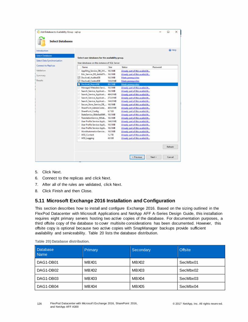
126 FlexPod Datacenter with Microsof t Exchange 2016, SharePoint 2016,
and NetApp AFF A300 © 2017 NetApp, Inc. All rights reserv ed.
5. Click Next.
6. Connect to the replicas and click Next.
7. After all of the rules are validated, click Next.
8. Click Finish and then Close.
5.11 Microsoft Exchange 2016 Installation and Configuration
This section describes how to install and configure Exchange 2016. Based on the sizing outlined in the
FlexPod Datacenter with Microsoft Applications and NetApp AFF A-Series Design Guide, this installation
requires eight primary servers hosting two active copies of the database. For documentation purposes, a
third offsite copy of the database to cover multisite considerations has been documented. However, this
offsite copy is optional because two active copies with SnapManager backups provide sufficient
availability and serviceability. Table 20 lists the database distribution.
Table 20) Database distribution.
Database
Name Primary Secondary Offsite
DAG1-DB01 MBX01 MBX02 SecMbx01
DAG1-DB02 MBX02 MBX03 SecMbx02
DAG1-DB03 MBX03 MBX04 SecMbx03
DAG1-DB04 MBX04 MBX05 SecMbx04
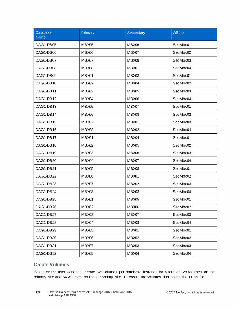
127 FlexPod Datacenter with Microsof t Exchange 2016, SharePoint 2016,
and NetApp AFF A300 © 2017 NetApp, Inc. All rights reserv ed.
Database
Name Primary Secondary Offsite
DAG1-DB05 MBX05 MBX06 SecMbx01
DAG1-DB06 MBX06 MBX07 SecMbx02
DAG1-DB07 MBX07 MBX08 SecMbx03
DAG1-DB08 MBX08 MBX01 SecMbx04
DAG1-DB09 MBX01 MBX03 SecMbx01
DAG1-DB10 MBX02 MBX04 SecMbx02
DAG1-DB11 MBX03 MBX05 SecMbx03
DAG1-DB12 MBX04 MBX06 SecMbx04
DAG1-DB13 MBX05 MBX07 SecMbx01
DAG1-DB14 MBX06 MBX08 SecMbx02
DAG1-DB15 MBX07 MBX01 SecMbx03
DAG1-DB16 MBX08 MBX02 SecMbx04
DAG1-DB17 MBX01 MBX04 SecMbx01
DAG1-DB18 MBX02 MBX05 SecMbx02
DAG1-DB19 MBX03 MBX06 SecMbx03
DAG1-DB20 MBX04 MBX07 SecMbx04
DAG1-DB21 MBX05 MBX08 SecMbx01
DAG1-DB22 MBX06 MBX01 SecMbx02
DAG1-DB23 MBX07 MBX02 SecMbx03
DAG1-DB24 MBX08 MBX03 SecMbx04
DAG1-DB25 MBX01 MBX05 SecMbx01
DAG1-DB26 MBX02 MBX06 SecMbx02
DAG1-DB27 MBX03 MBX07 SecMbx03
DAG1-DB28 MBX04 MBX08 SecMbx04
DAG1-DB29 MBX05 MBX01 SecMbx01
DAG1-DB30 MBX06 MBX02 SecMbx02
DAG1-DB31 MBX07 MBX03 SecMbx03
DAG1-DB32 MBX08 MBX04 SecMbx04
Create Volumes
Based on the user workload, create two volumes per database instance for a total of 128 volumes on the
primary site and 64 volumes on the secondary site. To create the volumes that house the LUNs for

128 FlexPod Datacenter with Microsof t Exchange 2016, SharePoint 2016,
and NetApp AFF A300 © 2017 NetApp, Inc. All rights reserv ed.
Exchange data and logs, use the OnCommand System Manager or PowerShell toolkit or enter the
commands into the storage management console. The following command shows the syntax necessary
to create a new database volume. The size of the volumes can be adjusted to meet your requirements.
volume create -vserver Exchange_SVM1 -volume DBx -aggregate aggrxx -size 3.6TB -space-guarantee
none -snapshot-policy none -foreground true -Security-style ntfs
volume create -vserver Exchange_SVM1 -volume LOGx -aggregate aggrxx size 625GB -space-guarantee
none snapshot-policy none -foreground true -Security-style ntfs
After the volumes are created, change the volume option to turn on Read Reallocate to improve
performance of the database reads.
vol modify -vserver Exchange_SVM1 -volume volume_name -read-realloc on
Create VMs
To install and configure an Exchange deployment for 10,000 active users, deploy the VMs listed in Table
21 on the vSphere environment. This table lists the VM configuration parameters for Microsoft 2016
installation.
Table 21) Microsoft Exchange 2016: VM configuration parameters.
Role Number of VMs RAM (GB) CPU HDD (GB)
Mailbox 8 64GB 8 450GB
1. Create the VMs listed in Table 21 and attach a virtual network interface in the MGMT network port group. The virtual network interface should be a VMXNET 3 adapter. After the VMs are created,
install Windows Server 2016 on them.
2. Install VMware Tools, assign the IP address and gateway in the MGMT subnet, and join the machine
to the AD domain.
3. Launch a PowerShell prompt by right-clicking the PowerShell icon in the taskbar and select Run as
Administrator.
4. Enable remote management and remote desktop by using the SCONFIG application.
SCONFIG
5. Select Configure Remote Management.
6. Select Enable Remote Management.
7. Select Return to the Main Menu.
8. Select Remote Desktop.
9. Enter E to enable.
10. Enter 2 to allow any version of remote desktop. You are returned to the main menu.
11. Select Exit to Command Line.
12. Add .NET 3.5 and multipath I/O features by running the following command:
Add-WindowsFeature NET-Framework-Core, Multipath-IO -IncludeManagementTools -Restart -Source
D:\Sources\Sxs
Note: SnapDrive for Windows requires .Net 3.5.
13. Configure local administrator access.
# SnapDrive service account
Add-LocalGroupMember -Group Administrators -Member Colts\SDWSVC
# SnapManager for Exchange Service Account
Add-LocalGroupMember -Group Administrators -Member COLTS\SMESVC
# Dedicated installation account

129 FlexPod Datacenter with Microsof t Exchange 2016, SharePoint 2016,
and NetApp AFF A300 © 2017 NetApp, Inc. All rights reserv ed.
Add-LocalGroupMember -Group Administrators -Member Colts\ExchInstall
Note: For future serviceability, NetApp recommends that you use a dedicated installation account that can be disabled after the software is deployed. This account can then be reenabled at any point in the future if access is denied.
14. Repeat steps 1 through 13 for each mailbox VM.
15. Install the Windows updates on the VM.
Configure iSCSI
To configure iSCSI connections from the mailbox VMs to the NetApp storage controllers, run the following
PowerShell commands from each host:
1. Start the iSCSI service.
Set-Service -Name MSiSCSI -StartupType Automatic
Start-Service -Name MSiSCSI
2. Configure iSCSI target portals for each path to the workload SVM.
New-IscsiTargetPortal -InitiatorPortalAddress <<SQL_VM_iSCSIA_IP>> -TargetPortalAddress
<<Work_SVM_iSCSI01a_IP>>
New-IscsiTargetPortal -InitiatorPortalAddress <<SQL_VM_iSCSIA_IP>> -TargetPortalAddress
<<Work_SVM_iSCSI02a_IP>>
New-IscsiTargetPortal -InitiatorPortalAddress <<SQL_VM_iSCSIB_IP>> -TargetPortalAddress
<<Work_SVM_iSCSI01b_IP>>
New-IscsiTargetPortal -InitiatorPortalAddress <<SQL_VM_iSCSIB_IP>> -TargetPortalAddress
<<Work_SVM_iSCSI02b_IP>>
3. Connect to the target for SharePoint SVM.
Get-IscsiTarget |Connect-IscsiTarget -IsPersistent $True -IsMultipathEnabled $True `
-InitiatorPortalAddress <<SQL_VM_iSCSIA_IP>> -TargetPortalAddress <<Work_SVM_iSCSI01a_IP>>
Get-IscsiTarget |Connect-IscsiTarget -IsPersistent $True -IsMultipathEnabled $True `
-InitiatorPortalAddress <<SQL_VM_iSCSIA_IP>> -TargetPortalAddress <<Work_SVM_iSCSI01b_IP>>
Get-IscsiTarget |Connect-IscsiTarget -IsPersistent $True -IsMultipathEnabled $True `
-InitiatorPortalAddress <<SQL_VM_iSCSIB_IP>> -TargetPortalAddress <<Work_SVM_iSCSI02a_IP>>
Get-IscsiTarget |Connect-IscsiTarget -IsPersistent $True -IsMultipathEnabled $True `
-InitiatorPortalAddress <<SQL_VM_iSCSIB_IP>> -TargetPortalAddress <<Work_SVM_iSCSI02b_IP>>
4. Verify the connections by running the following command:
Get-IscsiConnection
5. Configure MPIO for ONTAP.
New-MSDSMSupportedHW -VendorId NETAPP -ProductId "LUN C-Mode"
Update-MPIOClaimedHW -Confirm:$false
Restart-Computer
6. Repeat steps 1 through 5 for each mailbox VM.
SnapDrive for Windows
To install SnapDrive for Windows, run SnapDrive7.1.4_x64.exe as administrator and complete the
following steps by using the installation wizard:
1. On the SnapDrive Installation wizard home page, click Next.
2. Select Per Storage System as the license type. Click Next.
3. On the Customer Information page, enter the customer information. Click Next.
4. (Optional) Change the SnapDrive Installation folder. Click Next on the Destination Folder page.
5. Select the Enable SnapDrive to Communicate Through the Windows Firewall option and click Next.
6. Enter an account that can be used as a service account for the SnapDrive services. This account
must be a member of the built-in administrators group. Click Next.

130 FlexPod Datacenter with Microsof t Exchange 2016, SharePoint 2016,
and NetApp AFF A300 © 2017 NetApp, Inc. All rights reserv ed.
7. Make sure that the SnapDrive web service ports are not conflicting. Click Next.
8. On the Preferred Storage System IP Address page, select the Enable Preferred Storage System IP Address option. Specify the storage system to configure SnapDrive for management traffic. Click
Next.
9. On the Transport Protocol Default Setting page, select the Enable the Transport Protocol Settings
option. Enabling the transport protocol allows you to talk to the storage system.
Select the HTTPS option. Selecting HTTPS requires you to enter a user name, password, and port
ID. Click Next.
10. Click Next in the Unified Manager Configuration.
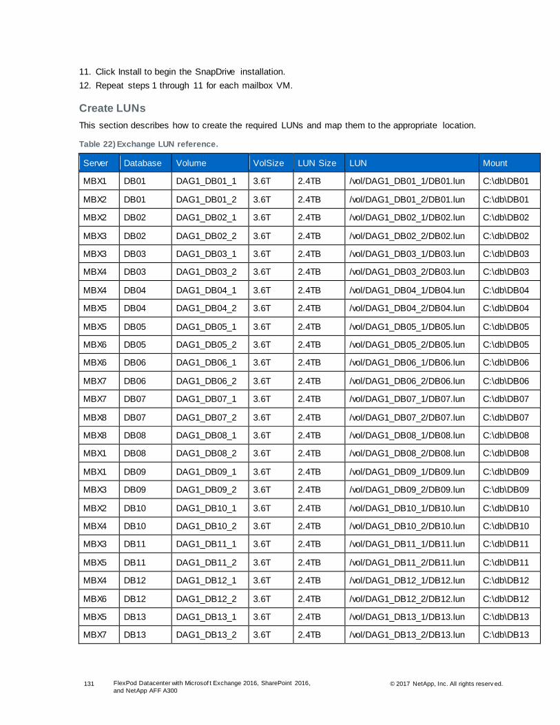
131 FlexPod Datacenter with Microsof t Exchange 2016, SharePoint 2016,
and NetApp AFF A300 © 2017 NetApp, Inc. All rights reserv ed.
11. Click Install to begin the SnapDrive installation.
12. Repeat steps 1 through 11 for each mailbox VM.
Create LUNs
This section describes how to create the required LUNs and map them to the appropriate location.
Table 22) Exchange LUN reference.
Server Database Volume VolSize LUN Size LUN Mount
MBX1 DB01 DAG1_DB01_1 3.6T 2.4TB /vol/DAG1_DB01_1/DB01.lun C:\db\DB01
MBX2 DB01 DAG1_DB01_2 3.6T 2.4TB /vol/DAG1_DB01_2/DB01.lun C:\db\DB01
MBX2 DB02 DAG1_DB02_1 3.6T 2.4TB /vol/DAG1_DB02_1/DB02.lun C:\db\DB02
MBX3 DB02 DAG1_DB02_2 3.6T 2.4TB /vol/DAG1_DB02_2/DB02.lun C:\db\DB02
MBX3 DB03 DAG1_DB03_1 3.6T 2.4TB /vol/DAG1_DB03_1/DB03.lun C:\db\DB03
MBX4 DB03 DAG1_DB03_2 3.6T 2.4TB /vol/DAG1_DB03_2/DB03.lun C:\db\DB03
MBX4 DB04 DAG1_DB04_1 3.6T 2.4TB /vol/DAG1_DB04_1/DB04.lun C:\db\DB04
MBX5 DB04 DAG1_DB04_2 3.6T 2.4TB /vol/DAG1_DB04_2/DB04.lun C:\db\DB04
MBX5 DB05 DAG1_DB05_1 3.6T 2.4TB /vol/DAG1_DB05_1/DB05.lun C:\db\DB05
MBX6 DB05 DAG1_DB05_2 3.6T 2.4TB /vol/DAG1_DB05_2/DB05.lun C:\db\DB05
MBX6 DB06 DAG1_DB06_1 3.6T 2.4TB /vol/DAG1_DB06_1/DB06.lun C:\db\DB06
MBX7 DB06 DAG1_DB06_2 3.6T 2.4TB /vol/DAG1_DB06_2/DB06.lun C:\db\DB06
MBX7 DB07 DAG1_DB07_1 3.6T 2.4TB /vol/DAG1_DB07_1/DB07.lun C:\db\DB07
MBX8 DB07 DAG1_DB07_2 3.6T 2.4TB /vol/DAG1_DB07_2/DB07.lun C:\db\DB07
MBX8 DB08 DAG1_DB08_1 3.6T 2.4TB /vol/DAG1_DB08_1/DB08.lun C:\db\DB08
MBX1 DB08 DAG1_DB08_2 3.6T 2.4TB /vol/DAG1_DB08_2/DB08.lun C:\db\DB08
MBX1 DB09 DAG1_DB09_1 3.6T 2.4TB /vol/DAG1_DB09_1/DB09.lun C:\db\DB09
MBX3 DB09 DAG1_DB09_2 3.6T 2.4TB /vol/DAG1_DB09_2/DB09.lun C:\db\DB09
MBX2 DB10 DAG1_DB10_1 3.6T 2.4TB /vol/DAG1_DB10_1/DB10.lun C:\db\DB10
MBX4 DB10 DAG1_DB10_2 3.6T 2.4TB /vol/DAG1_DB10_2/DB10.lun C:\db\DB10
MBX3 DB11 DAG1_DB11_1 3.6T 2.4TB /vol/DAG1_DB11_1/DB11.lun C:\db\DB11
MBX5 DB11 DAG1_DB11_2 3.6T 2.4TB /vol/DAG1_DB11_2/DB11.lun C:\db\DB11
MBX4 DB12 DAG1_DB12_1 3.6T 2.4TB /vol/DAG1_DB12_1/DB12.lun C:\db\DB12
MBX6 DB12 DAG1_DB12_2 3.6T 2.4TB /vol/DAG1_DB12_2/DB12.lun C:\db\DB12
MBX5 DB13 DAG1_DB13_1 3.6T 2.4TB /vol/DAG1_DB13_1/DB13.lun C:\db\DB13
MBX7 DB13 DAG1_DB13_2 3.6T 2.4TB /vol/DAG1_DB13_2/DB13.lun C:\db\DB13

132 FlexPod Datacenter with Microsof t Exchange 2016, SharePoint 2016,
and NetApp AFF A300 © 2017 NetApp, Inc. All rights reserv ed.
Server Database Volume VolSize LUN Size LUN Mount
MBX6 DB14 DAG1_DB14_1 3.6T 2.4TB /vol/DAG1_DB14_1/DB14.lun C:\db\DB14
MBX8 DB14 DAG1_DB14_2 3.6T 2.4TB /vol/DAG1_DB14_2/DB14.lun C:\db\DB14
MBX7 DB15 DAG1_DB15_1 3.6T 2.4TB /vol/DAG1_DB15_1/DB15.lun C:\db\DB15
MBX1 DB15 DAG1_DB15_2 3.6T 2.4TB /vol/DAG1_DB15_2/DB15.lun C:\db\DB15
MBX8 DB16 DAG1_DB16_1 3.6T 2.4TB /vol/DAG1_DB16_1/DB16.lun C:\db\DB16
MBX2 DB16 DAG1_DB16_2 3.6T 2.4TB /vol/DAG1_DB16_2/DB16.lun C:\db\DB16
MBX1 DB17 DAG1_DB17_1 3.6T 2.4TB /vol/DAG1_DB17_1/DB17.lun C:\db\DB17
MBX4 DB17 DAG1_DB17_2 3.6T 2.4TB /vol/DAG1_DB17_2/DB17.lun C:\db\DB17
MBX2 DB18 DAG1_DB18_1 3.6T 2.4TB /vol/DAG1_DB18_1/DB18.lun C:\db\DB18
MBX5 DB18 DAG1_DB18_2 3.6T 2.4TB /vol/DAG1_DB18_2/DB18.lun C:\db\DB18
MBX3 DB19 DAG1_DB19_1 3.6T 2.4TB /vol/DAG1_DB19_1/DB19.lun C:\db\DB19
MBX6 DB19 DAG1_DB19_2 3.6T 2.4TB /vol/DAG1_DB19_2/DB19.lun C:\db\DB19
MBX4 DB20 DAG1_DB20_1 3.6T 2.4TB /vol/DAG1_DB20_1/DB20.lun C:\db\DB20
MBX7 DB20 DAG1_DB20_2 3.6T 2.4TB /vol/DAG1_DB20_2/DB20.lun C:\db\DB20
MBX5 DB21 DAG1_DB21_1 3.6T 2.4TB /vol/DAG1_DB21_1/DB21.lun C:\db\DB21
MBX8 DB21 DAG1_DB21_2 3.6T 2.4TB /vol/DAG1_DB21_2/DB21.lun C:\db\DB21
MBX6 DB22 DAG1_DB22_1 3.6T 2.4TB /vol/DAG1_DB22_1/DB22.lun C:\db\DB22
MBX1 DB22 DAG1_DB22_2 3.6T 2.4TB /vol/DAG1_DB22_2/DB22.lun C:\db\DB22
MBX7 DB23 DAG1_DB23_1 3.6T 2.4TB /vol/DAG1_DB23_1/DB23.lun C:\db\DB23
MBX2 DB23 DAG1_DB23_2 3.6T 2.4TB /vol/DAG1_DB23_2/DB23.lun C:\db\DB23
MBX8 DB24 DAG1_DB24_1 3.6T 2.4TB /vol/DAG1_DB24_1/DB24.lun C:\db\DB24
MBX3 DB24 DAG1_DB24_2 3.6T 2.4TB /vol/DAG1_DB24_2/DB24.lun C:\db\DB24
MBX1 DB25 DAG1_DB25_1 3.6T 2.4TB /vol/DAG1_DB25_1/DB25.lun C:\db\DB25
MBX5 DB25 DAG1_DB25_2 3.6T 2.4TB /vol/DAG1_DB25_2/DB25.lun C:\db\DB25
MBX2 DB26 DAG1_DB26_1 3.6T 2.4TB /vol/DAG1_DB26_1/DB26.lun C:\db\DB26
MBX6 DB26 DAG1_DB26_2 3.6T 2.4TB /vol/DAG1_DB26_2/DB26.lun C:\db\DB26
MBX3 DB27 DAG1_DB27_1 3.6T 2.4TB /vol/DAG1_DB27_1/DB27.lun C:\db\DB27
MBX7 DB27 DAG1_DB27_2 3.6T 2.4TB /vol/DAG1_DB27_2/DB27.lun C:\db\DB27
MBX4 DB28 DAG1_DB28_1 3.6T 2.4TB /vol/DAG1_DB28_1/DB28.lun C:\db\DB28
MBX8 DB28 DAG1_DB28_2 3.6T 2.4TB /vol/DAG1_DB28_2/DB28.lun C:\db\DB28
MBX5 DB29 DAG1_DB29_1 3.6T 2.4TB /vol/DAG1_DB29_1/DB29.lun C:\db\DB29
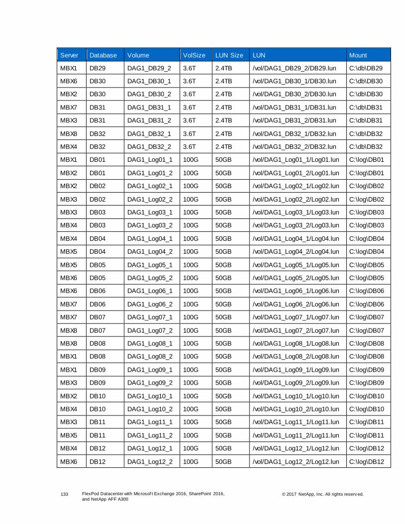
133 FlexPod Datacenter with Microsof t Exchange 2016, SharePoint 2016,
and NetApp AFF A300 © 2017 NetApp, Inc. All rights reserv ed.
Server Database Volume VolSize LUN Size LUN Mount
MBX1 DB29 DAG1_DB29_2 3.6T 2.4TB /vol/DAG1_DB29_2/DB29.lun C:\db\DB29
MBX6 DB30 DAG1_DB30_1 3.6T 2.4TB /vol/DAG1_DB30_1/DB30.lun C:\db\DB30
MBX2 DB30 DAG1_DB30_2 3.6T 2.4TB /vol/DAG1_DB30_2/DB30.lun C:\db\DB30
MBX7 DB31 DAG1_DB31_1 3.6T 2.4TB /vol/DAG1_DB31_1/DB31.lun C:\db\DB31
MBX3 DB31 DAG1_DB31_2 3.6T 2.4TB /vol/DAG1_DB31_2/DB31.lun C:\db\DB31
MBX8 DB32 DAG1_DB32_1 3.6T 2.4TB /vol/DAG1_DB32_1/DB32.lun C:\db\DB32
MBX4 DB32 DAG1_DB32_2 3.6T 2.4TB /vol/DAG1_DB32_2/DB32.lun C:\db\DB32
MBX1 DB01 DAG1_Log01_1 100G 50GB /vol/DAG1_Log01_1/Log01.lun C:\log\DB01
MBX2 DB01 DAG1_Log01_2 100G 50GB /vol/DAG1_Log01_2/Log01.lun C:\log\DB01
MBX2 DB02 DAG1_Log02_1 100G 50GB /vol/DAG1_Log02_1/Log02.lun C:\log\DB02
MBX3 DB02 DAG1_Log02_2 100G 50GB /vol/DAG1_Log02_2/Log02.lun C:\log\DB02
MBX3 DB03 DAG1_Log03_1 100G 50GB /vol/DAG1_Log03_1/Log03.lun C:\log\DB03
MBX4 DB03 DAG1_Log03_2 100G 50GB /vol/DAG1_Log03_2/Log03.lun C:\log\DB03
MBX4 DB04 DAG1_Log04_1 100G 50GB /vol/DAG1_Log04_1/Log04.lun C:\log\DB04
MBX5 DB04 DAG1_Log04_2 100G 50GB /vol/DAG1_Log04_2/Log04.lun C:\log\DB04
MBX5 DB05 DAG1_Log05_1 100G 50GB /vol/DAG1_Log05_1/Log05.lun C:\log\DB05
MBX6 DB05 DAG1_Log05_2 100G 50GB /vol/DAG1_Log05_2/Log05.lun C:\log\DB05
MBX6 DB06 DAG1_Log06_1 100G 50GB /vol/DAG1_Log06_1/Log06.lun C:\log\DB06
MBX7 DB06 DAG1_Log06_2 100G 50GB /vol/DAG1_Log06_2/Log06.lun C:\log\DB06
MBX7 DB07 DAG1_Log07_1 100G 50GB /vol/DAG1_Log07_1/Log07.lun C:\log\DB07
MBX8 DB07 DAG1_Log07_2 100G 50GB /vol/DAG1_Log07_2/Log07.lun C:\log\DB07
MBX8 DB08 DAG1_Log08_1 100G 50GB /vol/DAG1_Log08_1/Log08.lun C:\log\DB08
MBX1 DB08 DAG1_Log08_2 100G 50GB /vol/DAG1_Log08_2/Log08.lun C:\log\DB08
MBX1 DB09 DAG1_Log09_1 100G 50GB /vol/DAG1_Log09_1/Log09.lun C:\log\DB09
MBX3 DB09 DAG1_Log09_2 100G 50GB /vol/DAG1_Log09_2/Log09.lun C:\log\DB09
MBX2 DB10 DAG1_Log10_1 100G 50GB /vol/DAG1_Log10_1/Log10.lun C:\log\DB10
MBX4 DB10 DAG1_Log10_2 100G 50GB /vol/DAG1_Log10_2/Log10.lun C:\log\DB10
MBX3 DB11 DAG1_Log11_1 100G 50GB /vol/DAG1_Log11_1/Log11.lun C:\log\DB11
MBX5 DB11 DAG1_Log11_2 100G 50GB /vol/DAG1_Log11_2/Log11.lun C:\log\DB11
MBX4 DB12 DAG1_Log12_1 100G 50GB /vol/DAG1_Log12_1/Log12.lun C:\log\DB12
MBX6 DB12 DAG1_Log12_2 100G 50GB /vol/DAG1_Log12_2/Log12.lun C:\log\DB12

134 FlexPod Datacenter with Microsof t Exchange 2016, SharePoint 2016,
and NetApp AFF A300 © 2017 NetApp, Inc. All rights reserv ed.
Server Database Volume VolSize LUN Size LUN Mount
MBX5 DB13 DAG1_Log13_1 100G 50GB /vol/DAG1_Log13_1/Log13.lun C:\log\DB13
MBX7 DB13 DAG1_Log13_2 100G 50GB /vol/DAG1_Log13_2/Log13.lun C:\log\DB13
MBX6 DB14 DAG1_Log14_1 100G 50GB /vol/DAG1_Log14_1/Log14.lun C:\log\DB14
MBX8 DB14 DAG1_Log14_2 100G 50GB /vol/DAG1_Log14_2/Log14.lun C:\log\DB14
MBX7 DB15 DAG1_Log15_1 100G 50GB /vol/DAG1_Log15_1/Log15.lun C:\log\DB15
MBX1 DB15 DAG1_Log15_2 100G 50GB /vol/DAG1_Log15_2/Log15.lun C:\log\DB15
MBX8 DB16 DAG1_Log16_1 100G 50GB /vol/DAG1_Log16_1/Log16.lun C:\log\DB16
MBX2 DB16 DAG1_Log16_2 100G 50GB /vol/DAG1_Log16_2/Log16.lun C:\log\DB16
MBX1 DB17 DAG1_Log17_1 100G 50GB /vol/DAG1_Log17_1/Log17.lun C:\log\DB17
MBX4 DB17 DAG1_Log17_2 100G 50GB /vol/DAG1_Log17_2/Log17.lun C:\log\DB17
MBX2 DB18 DAG1_Log18_1 100G 50GB /vol/DAG1_Log18_1/Log18.lun C:\log\DB18
MBX5 DB18 DAG1_Log18_2 100G 50GB /vol/DAG1_Log18_2/Log18.lun C:\log\DB18
MBX3 DB19 DAG1_Log19_1 100G 50GB /vol/DAG1_Log19_1/Log19.lun C:\log\DB19
MBX6 DB19 DAG1_Log19_2 100G 50GB /vol/DAG1_Log19_2/Log19.lun C:\log\DB19
MBX4 DB20 DAG1_Log20_1 100G 50GB /vol/DAG1_Log20_1/Log20.lun C:\log\DB20
MBX7 DB20 DAG1_Log20_2 100G 50GB /vol/DAG1_Log20_2/Log20.lun C:\log\DB20
MBX5 DB21 DAG1_Log21_1 100G 50GB /vol/DAG1_Log21_1/Log21.lun C:\log\DB21
MBX8 DB21 DAG1_Log21_2 100G 50GB /vol/DAG1_Log21_2/Log21.lun C:\log\DB21
MBX6 DB22 DAG1_Log22_1 100G 50GB /vol/DAG1_Log22_1/Log22.lun C:\log\DB22
MBX1 DB22 DAG1_Log22_2 100G 50GB /vol/DAG1_Log22_2/Log22.lun C:\log\DB22
MBX7 DB23 DAG1_Log23_1 100G 50GB /vol/DAG1_Log23_1/Log23.lun C:\log\DB23
MBX2 DB23 DAG1_Log23_2 100G 50GB /vol/DAG1_Log23_2/Log23.lun C:\log\DB23
MBX8 DB24 DAG1_Log24_1 100G 50GB /vol/DAG1_Log24_1/Log24.lun C:\log\DB24
MBX3 DB24 DAG1_Log24_2 100G 50GB /vol/DAG1_Log24_2/Log24.lun C:\log\DB24
MBX1 DB25 DAG1_Log25_1 100G 50GB /vol/DAG1_Log25_1/Log25.lun C:\log\DB25
MBX5 DB25 DAG1_Log25_2 100G 50GB /vol/DAG1_Log25_2/Log25.lun C:\log\DB25
MBX2 DB26 DAG1_Log26_1 100G 50GB /vol/DAG1_Log26_1/Log26.lun C:\log\DB26
MBX6 DB26 DAG1_Log26_2 100G 50GB /vol/DAG1_Log26_2/Log26.lun C:\log\DB26
MBX3 DB27 DAG1_Log27_1 100G 50GB /vol/DAG1_Log27_1/Log27.lun C:\log\DB27
MBX7 DB27 DAG1_Log27_2 100G 50GB /vol/DAG1_Log27_2/Log27.lun C:\log\DB27
MBX4 DB28 DAG1_Log28_1 100G 50GB /vol/DAG1_Log28_1/Log28.lun C:\log\DB28

135 FlexPod Datacenter with Microsof t Exchange 2016, SharePoint 2016,
and NetApp AFF A300 © 2017 NetApp, Inc. All rights reserv ed.
Server Database Volume VolSize LUN Size LUN Mount
MBX8 DB28 DAG1_Log28_2 100G 50GB /vol/DAG1_Log28_2/Log28.lun C:\log\DB28
MBX5 DB29 DAG1_Log29_1 100G 50GB /vol/DAG1_Log29_1/Log29.lun C:\log\DB29
MBX1 DB29 DAG1_Log29_2 100G 50GB /vol/DAG1_Log29_2/Log29.lun C:\log\DB29
MBX6 DB30 DAG1_Log30_1 100G 50GB /vol/DAG1_Log30_1/Log30.lun C:\log\DB30
MBX2 DB30 DAG1_Log30_2 100G 50GB /vol/DAG1_Log30_2/Log30.lun C:\log\DB30
MBX7 DB31 DAG1_Log31_1 100G 50GB /vol/DAG1_Log31_1/Log31.lun C:\log\DB31
MBX3 DB31 DAG1_Log31_2 100G 50GB /vol/DAG1_Log31_2/Log31.lun C:\log\DB31
MBX8 DB32 DAG1_Log32_1 100G 50GB /vol/DAG1_Log32_1/Log32.lun C:\log\DB32
MBX4 DB32 DAG1_Log32_2 100G 50GB /vol/DAG1_Log32_2/Log32.lun C:\log\DB32
NetApp recommends using SnapDrive for Windows to create the LUNs to house the databases and logs
for your Exchange servers. There are two methods available to create the LUNs: use the SDW GUI or the
SDCLI. The following examples use the SDCLI method.
sdcli disk create -dtype dedicated -m mailbox1 -D c:\DB\DBx -p Share-SVM:/vol/DBx/DBx.lun -I
initiatorname -z lunsize
Use the following environment variables for the SDCLI:
-m: machine name
-D: mount point location
-p: path to the volume where the LUN is created
-I: initiator name
-z: LUN size
Change the variables to meet the requirements of your environment.
Install Exchange 2016 Prerequisites
The VMs are ready to use. Before you install Exchange 2016, you need to install the SharePoint
prerequisites.
1. Install Windows Server 2016 prerequisites for the mailbox role.
Install-WindowsFeature NET-Framework-45-Features, RPC-over-HTTP-proxy, RSAT-Clustering, RSAT-
Clustering-CmdInterface, RSAT-Clustering-Mgmt, RSAT-Clustering-PowerShell, Web-Mgmt-Console, WAS-
Process-Model, Web-Asp-Net45, Web-Basic-Auth, Web-Client-Auth, Web-Digest-Auth, Web-Dir-Browsing,
Web-Dyn-Compression, Web-Http-Errors, Web-Http-Logging, Web-Http-Redirect, Web-Http-Tracing, Web-
ISAPI-Ext, Web-ISAPI-Filter, Web-Lgcy-Mgmt-Console, Web-Metabase, Web-Mgmt-Console, Web-Mgmt-
Service, Web-Net-Ext45, Web-Request-Monitor, Web-Server, Web-Stat-Compression, Web-Static-
Content, Web-Windows-Auth, Web-WMI, Windows-Identity-Foundation, RSAT-ADDS
2. Repeat step 1 for each Exchange VM.
Install Unified Communications Management API 4.0
To install Unified Communications Management API 4.0 Runtime, complete the following steps:
1. Download the Unified Communications Managed API 4.0 Runtime:
http://www.microsoft.com/en-us/download/details.aspx?id=34992.
2. Right-click the UcmaRuntimeSetup.exe file and select Run As Administrator.

136 FlexPod Datacenter with Microsof t Exchange 2016, SharePoint 2016,
and NetApp AFF A300 © 2017 NetApp, Inc. All rights reserv ed.
3. In the introduction window, click Next.
4. Review and accept the license terms and click Install.
5. Click Finish to complete the installation.
6. Repeat steps 1 through 5 for each Exchange VM.
Prepare Active Directory for Exchange Server 2016 U6
This section describes how to prepare Active Directory for the Exchange 2016 installation.
Extend Active Directory Schema
To extend the AD schema, complete the following steps:
1. Run setup.exe from the Exchange distribution with the parameters listed in step 2.
Note: This operation must be executed just one time from a single server.
2. Open an elevated command prompt and run the following command to extend the AD schema:
Setup.exe /PrepareSchema /IAcceptExchangeServerLicenseTerms
Prepare AD
To prepare AD, complete the following steps:
1. Run setup.exe from the Exchange distribution with the parameters listed in step 2.
Note: This operation must be executed just one time from a single server.
2. Open an elevated command prompt and run the following command to prepare AD:
Setup.exe /PrepareAD /OrganizationName:”Colts” /IAcceptExchangeServerLicenseTerms

137 FlexPod Datacenter with Microsof t Exchange 2016, SharePoint 2016,
and NetApp AFF A300 © 2017 NetApp, Inc. All rights reserv ed.
Prepare AD Domains
To prepare the AD domains, complete the following steps:
1. Run setup.exe from the Exchange distribution with the parameters listed in step 2.
Note: This operation must be executed just one time from a single server.
2. Open an elevated command prompt and run the following command to prepare AD domains:
Setup.exe /PrepareAllDomains /IAcceptExchangeServerLicenseTerms
Verify AD Preparation
To verify the AD preparation, complete the following steps:
1. Open ADSI Edit.
2. Right-click ADSI Edit in the navigation pane and click Connect.
3. In Connection Settings, select the Select a Well-Known Naming Context option and then select
Configuration. Click OK.
4. Expand Configuration [<domain FQDN>], CN=Configuration, DC=domain, DC=com, CN=Services,
CN=Microsoft Exchange.

138 FlexPod Datacenter with Microsof t Exchange 2016, SharePoint 2016,
and NetApp AFF A300 © 2017 NetApp, Inc. All rights reserv ed.
5. Right-click CN=<your Exchange organization name> and then select Properties.
6. Make sure the value in msExchangeProductId matches the value in the Exchange 2016 Active
Directory versions table for the version of Exchange 2016 you are installing.
Install Exchange Server 2016 Mailbox Role
To perform an unattended installation of Exchange 2016, complete the following steps:
1. Run the following command from the Exchange 2016 installation directory to install the mailbox role:
Setup.exe /mode:Install /r:Mailbox /IAcceptExchangeServerLicenseTerms
2. Enter the product key by using the Exchange Management Shell.
Set-ExchangeServer $env:COMPUTERNAME -ProductKey *****-*****-****-*****-*****
3. Restart the MSExchangeIS service for the new key to take effect.
4. Verify that the Exchange enterprise license has taken effect.
Get-ExchangeServer | fl Name,Edition,ServerRole,
AdminDisplayVersion,IsExchangeTrialEdition

139 FlexPod Datacenter with Microsof t Exchange 2016, SharePoint 2016,
and NetApp AFF A300 © 2017 NetApp, Inc. All rights reserv ed.
5. Restart the computer to finalize the installation.
6. Repeat steps 1 through 5 on the remaining Exchange servers.
Note: At the time of this validation, the CU6 installer failed to stage the necessary file. This resulted in errors related to the autodiscover service. Copy the following shared web configuration file to the ClientAccess root installation folder if the SharedWebConfig.config file is missing.
copy "C:\Program Files\Microsoft\Exchange Server\V15\FrontEnd\HttpProxy\SharedWebConfig.config"
"C:\Program Files\Microsoft\Exchange Server\V15\ClientAccess\SharedWebConfig.config"
Configure Mail Flow
To configure mail flow, complete the following steps:
1. Open the EAC by browsing to https://localhost/ecp on any of the mailbox servers.
2. Enter your user name and password and click Sign in.
3. In the left pane, click Mail Flow and then select Send Connecters in the top-right pane. Click the +
symbol to add a new connector.
4. In the New Send Connector wizard, enter the name for the new send connecter and then select
Internet. Click Next.
5. Select the MX Record Associated with Recipient Domain option and click Next.
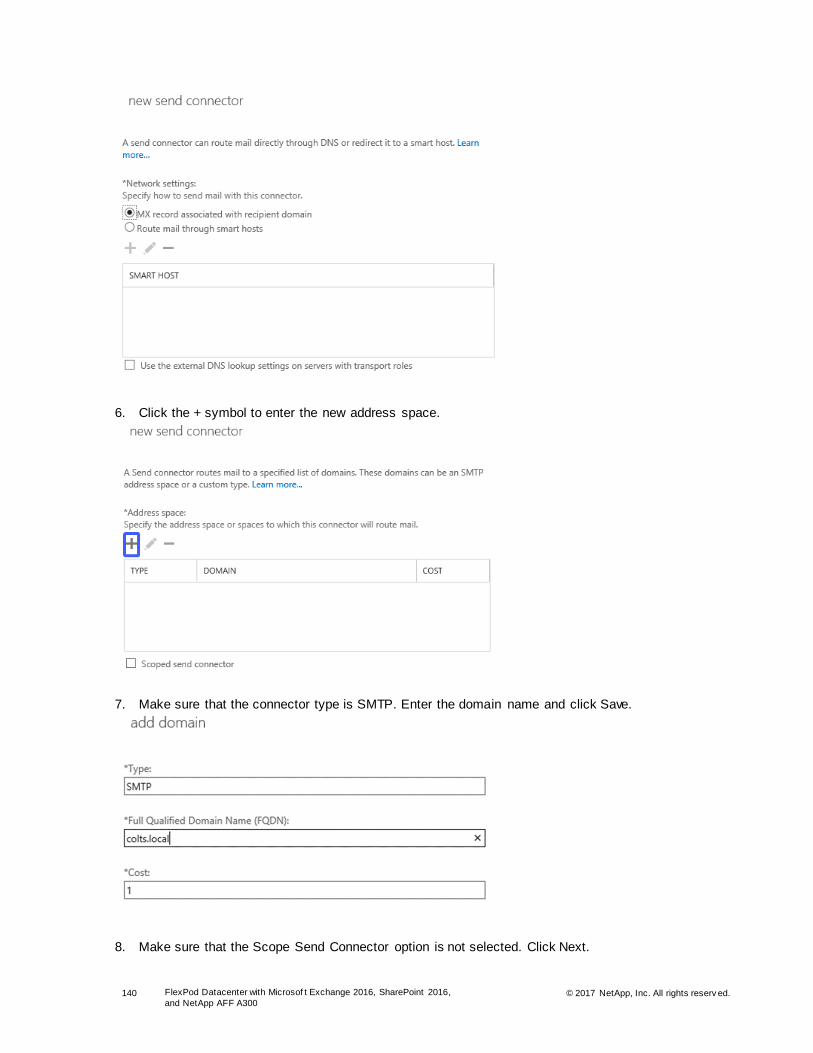
140 FlexPod Datacenter with Microsof t Exchange 2016, SharePoint 2016,
and NetApp AFF A300 © 2017 NetApp, Inc. All rights reserv ed.
6. Click the + symbol to enter the new address space.
7. Make sure that the connector type is SMTP. Enter the domain name and click Save.
8. Make sure that the Scope Send Connector option is not selected. Click Next.

141 FlexPod Datacenter with Microsof t Exchange 2016, SharePoint 2016,
and NetApp AFF A300 © 2017 NetApp, Inc. All rights reserv ed.
9. Click the + symbol to add the source servers.
10. Select all of Exchange servers that run the mailbox role and click add. Click OK.
11. Click Finish to complete the wizard.

142 FlexPod Datacenter with Microsof t Exchange 2016, SharePoint 2016,
and NetApp AFF A300 © 2017 NetApp, Inc. All rights reserv ed.
12. Verify that the new connection was created successfully.
Install Microsoft Exchange Management Tools on Remote Management Computer
Log in to the remote management computer. Open a command window and navigate to the Exchange
installation files. The file location might be on a network share.
1. Run the following command:
Setup.exe /Role:ManagementTools /IAcceptExchangeServerLicenseTerms
Configure DNS
The DNS configuration for any solution is dependent on whether the use case and budget justify a unified
or dedicated namespace. For this reference implementation, NetApp chose an alternate configuration: a
unified namespace that spanned two physical locations to provide enhanced availability with a hot
standby third DAG copy. A basic layer 4 load balancer was implemented without session affiant to
enforce the active/passive site model. This configuration allowed NetApp to validate the full load on the
primary site, while showing how easy it was to add site resiliency to any deployment.
Note: If you are deploying a full active/active DAG, you can use a round-robin DNS instead of a load balancer by adding a fourth DAG copy in the secondary site.
1. Create a DNS record pointing to the load balancer virtual IP.
Dnscmd /RecordAdd colts.local autodiscover A 172.21.91.199
dnscmd /RecordAdd colts.local mail A 172.21.91.199
2. Create an MX record.
dnscmd /recordadd colts.local @ MX 10 mail.colts.local
Configure Exchange Services
Use the data in Table 23 to reconfigure each mailbox server to use the DNS alias.
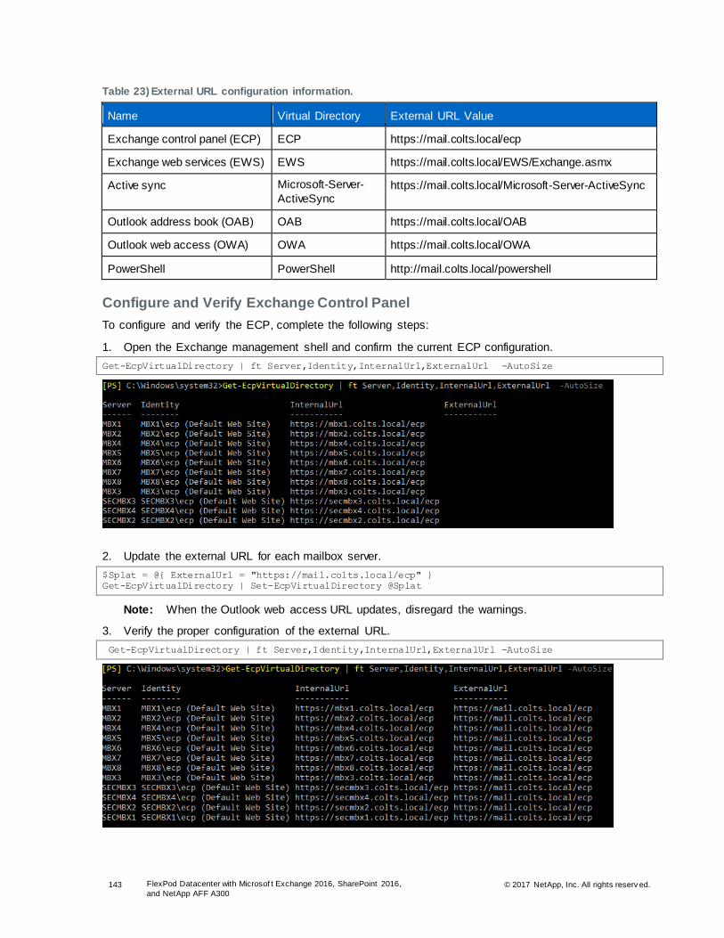
143 FlexPod Datacenter with Microsof t Exchange 2016, SharePoint 2016,
and NetApp AFF A300 © 2017 NetApp, Inc. All rights reserv ed.
Table 23) External URL configuration information.
Name Virtual Directory External URL Value
Exchange control panel (ECP) ECP https://mail.colts.local/ecp
Exchange web services (EWS) EWS https://mail.colts.local/EWS/Exchange.asmx
Active sync Microsoft-Server-
ActiveSync https://mail.colts.local/Microsoft-Server-ActiveSync
Outlook address book (OAB) OAB https://mail.colts.local/OAB
Outlook web access (OWA) OWA https://mail.colts.local/OWA
PowerShell PowerShell http://mail.colts.local/powershell
Configure and Verify Exchange Control Panel
To configure and verify the ECP, complete the following steps:
1. Open the Exchange management shell and confirm the current ECP configuration.
Get-EcpVirtualDirectory | ft Server,Identity,InternalUrl,ExternalUrl -AutoSize
2. Update the external URL for each mailbox server.
$Splat = @{ ExternalUrl = "https://mail.colts.local/ecp" }
Get-EcpVirtualDirectory | Set-EcpVirtualDirectory @Splat
Note: When the Outlook web access URL updates, disregard the warnings.
3. Verify the proper configuration of the external URL.
Get-EcpVirtualDirectory | ft Server,Identity,InternalUrl,ExternalUrl -AutoSize

144 FlexPod Datacenter with Microsof t Exchange 2016, SharePoint 2016,
and NetApp AFF A300 © 2017 NetApp, Inc. All rights reserv ed.
Configure and Verify Exchange Web Services
To configure and verify the EWS configuration, complete the following steps:
1. Open the Exchange management shell and confirm the current EWS configuration.
Get-WebServicesVirtualDirectory | ft Server,Identity,InternalUrl,ExternalUrl -AutoSize
2. Update the external URL for each mailbox server.
$Splat = @{ ExternalUrl = "https://mail.colts.local/EWS/Exchange.asmx" }
Get-WebServicesVirtualDirectory | Set-WebServicesVirtualDirectory @Splat
3. Verify that the external URL is configured.
Get-WebServicesVirtualDirectory | ft Server,InternalUrl,ExternalUrl -AutoSize
Configure and Verify Active Sync
To configure and verify the current active sync configuration, complete the following steps:
1. Open the Exchange management shell and confirm the current active sync configuration.
Get-ActiveSyncVirtualDirectory | fl Server,Identity,InternalUrl,ExternalUrl
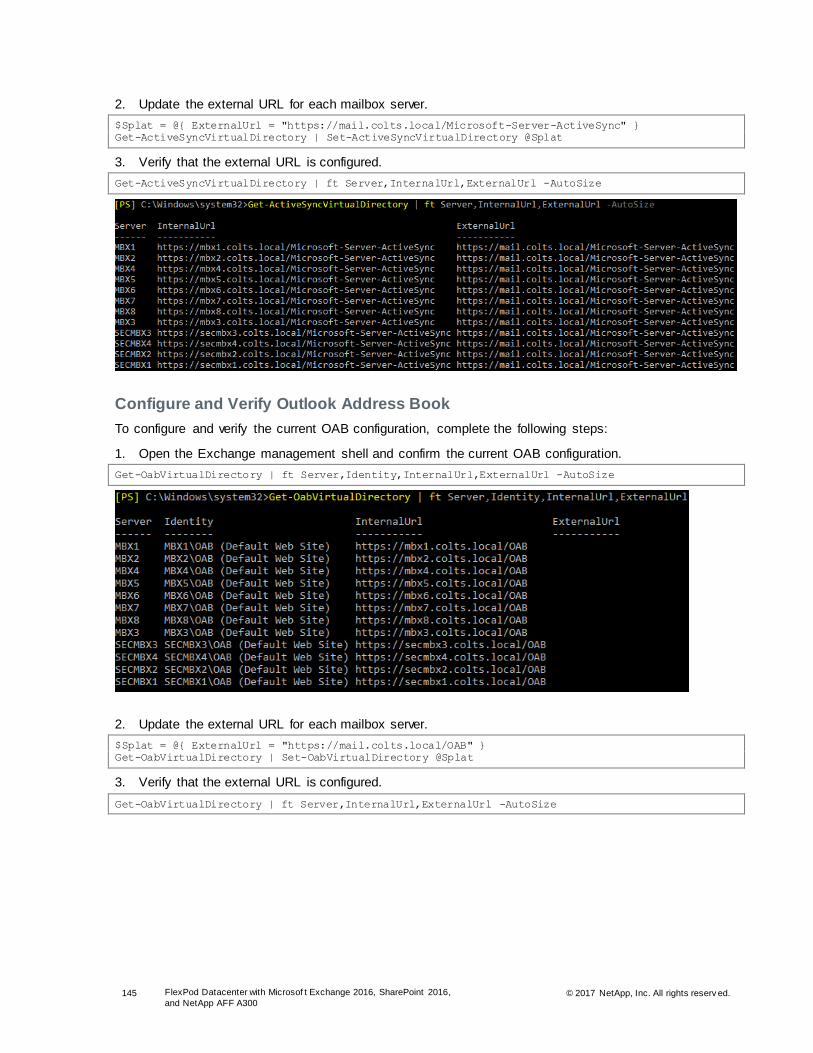
145 FlexPod Datacenter with Microsof t Exchange 2016, SharePoint 2016,
and NetApp AFF A300 © 2017 NetApp, Inc. All rights reserv ed.
2. Update the external URL for each mailbox server.
$Splat = @{ ExternalUrl = "https://mail.colts.local/Microsoft-Server-ActiveSync" }
Get-ActiveSyncVirtualDirectory | Set-ActiveSyncVirtualDirectory @Splat
3. Verify that the external URL is configured.
Get-ActiveSyncVirtualDirectory | ft Server,InternalUrl,ExternalUrl -AutoSize
Configure and Verify Outlook Address Book
To configure and verify the current OAB configuration, complete the following steps:
1. Open the Exchange management shell and confirm the current OAB configuration.
Get-OabVirtualDirectory | ft Server,Identity,InternalUrl,ExternalUrl -AutoSize
2. Update the external URL for each mailbox server.
$Splat = @{ ExternalUrl = "https://mail.colts.local/OAB" }
Get-OabVirtualDirectory | Set-OabVirtualDirectory @Splat
3. Verify that the external URL is configured.
Get-OabVirtualDirectory | ft Server,InternalUrl,ExternalUrl -AutoSize

146 FlexPod Datacenter with Microsof t Exchange 2016, SharePoint 2016,
and NetApp AFF A300 © 2017 NetApp, Inc. All rights reserv ed.
Configure and Verify Outlook Web Access
To configure and verify the current OWA configuration, complete the following steps:
1. Open the Exchange management shell and confirm the current OWA configuration.
Get-OwaVirtualDirectory | ft Server,Identity,InternalUrl,ExternalUrl -AutoSize
2. Update the external URL for each mailbox server.
$Splat = @{ ExternalUrl = "https://mail.colts.local/owa" }
Get-OwaVirtualDirectory | Set-OwaVirtualDirectory @Splat
3. Verify that the external URL is configured.
Get-OwaVirtualDirectory | FT Server,InternalUrl,ExternalUrl -AutoSize

147 FlexPod Datacenter with Microsof t Exchange 2016, SharePoint 2016,
and NetApp AFF A300 © 2017 NetApp, Inc. All rights reserv ed.
Configure and Verify PowerShell
To configure and verify the current PowerShell configuration, complete the following steps:
1. Open the Exchange management shell and confirm the current PowerShell configuration.
Get-PowerShellVirtualDirectory | ft Server,Identity,InternalUrl,ExternalUrl -AutoSize
2. Update the external URL for each mailbox server.
$Splat = @{ ExternalUrl = "https://mail.colts.local/powershell" }
Get-PowerShellVirtualDirectory | Set-PowerShellVirtualDirectory @Splat
3. Verify that the external URL is configured.
Get-PowerShellVirtualDirectory | ft Server,InternalUrl,ExternalUrl -AutoSize
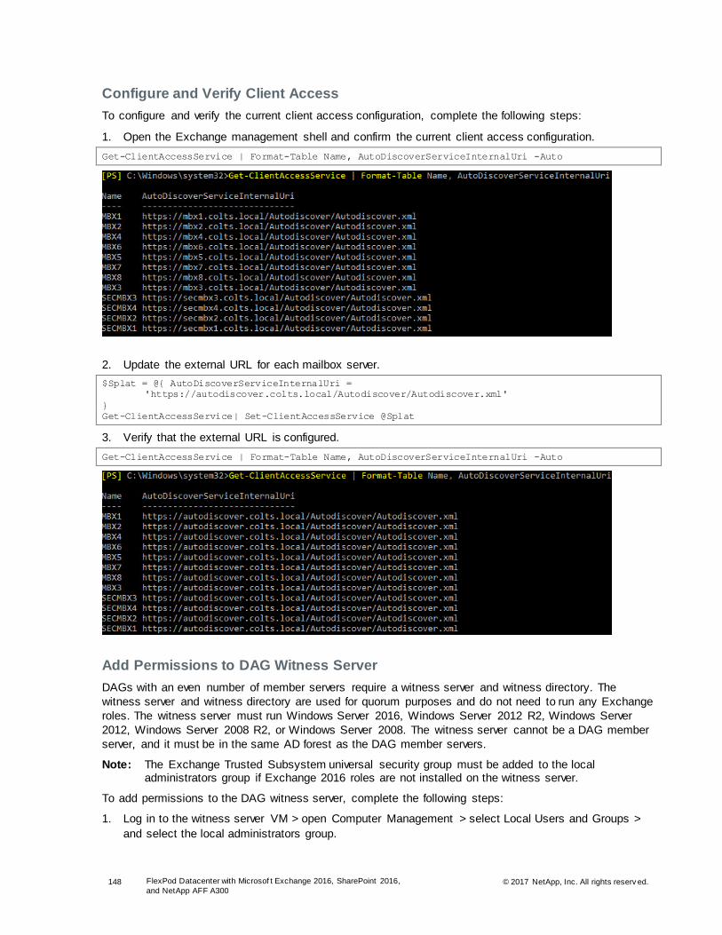
148 FlexPod Datacenter with Microsof t Exchange 2016, SharePoint 2016,
and NetApp AFF A300 © 2017 NetApp, Inc. All rights reserv ed.
Configure and Verify Client Access
To configure and verify the current client access configuration, complete the following steps:
1. Open the Exchange management shell and confirm the current client access configuration.
Get-ClientAccessService | Format-Table Name, AutoDiscoverServiceInternalUri -Auto
2. Update the external URL for each mailbox server.
$Splat = @{ AutoDiscoverServiceInternalUri =
'https://autodiscover.colts.local/Autodiscover/Autodiscover.xml'
}
Get-ClientAccessService| Set-ClientAccessService @Splat
3. Verify that the external URL is configured.
Get-ClientAccessService | Format-Table Name, AutoDiscoverServiceInternalUri -Auto
Add Permissions to DAG Witness Server
DAGs with an even number of member servers require a witness server and witness directory. The
witness server and witness directory are used for quorum purposes and do not need to run any Exchange
roles. The witness server must run Windows Server 2016, Windows Server 2012 R2, Windows Server
2012, Windows Server 2008 R2, or Windows Server 2008. The witness server cannot be a DAG member
server, and it must be in the same AD forest as the DAG member servers.
Note: The Exchange Trusted Subsystem universal security group must be added to the local administrators group if Exchange 2016 roles are not installed on the witness server.
To add permissions to the DAG witness server, complete the following steps:
1. Log in to the witness server VM > open Computer Management > select Local Users and Groups >
and select the local administrators group.
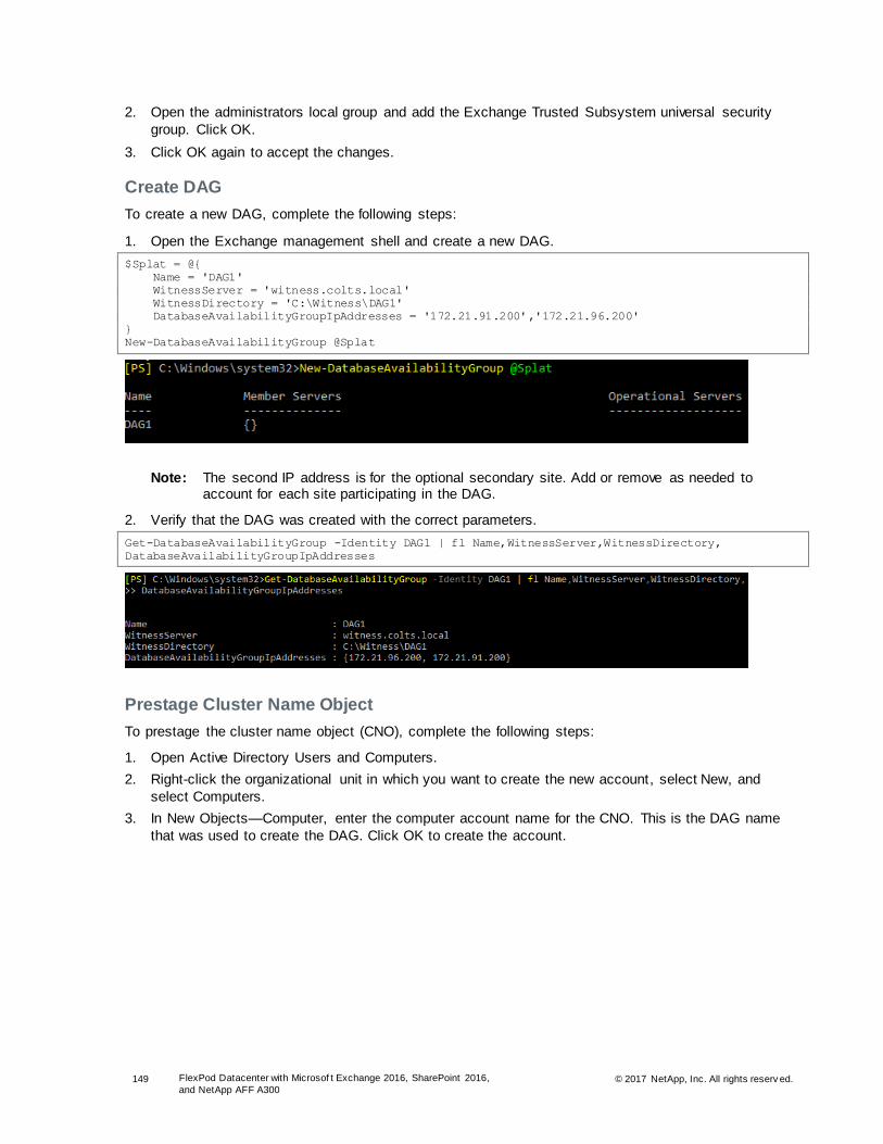
149 FlexPod Datacenter with Microsof t Exchange 2016, SharePoint 2016,
and NetApp AFF A300 © 2017 NetApp, Inc. All rights reserv ed.
2. Open the administrators local group and add the Exchange Trusted Subsystem universal security
group. Click OK.
3. Click OK again to accept the changes.
Create DAG
To create a new DAG, complete the following steps:
1. Open the Exchange management shell and create a new DAG.
$Splat = @{
Name = 'DAG1'
WitnessServer = 'witness.colts.local'
WitnessDirectory = 'C:\Witness\DAG1'
DatabaseAvailabilityGroupIpAddresses = '172.21.91.200','172.21.96.200'
}
New-DatabaseAvailabilityGroup @Splat
Note: The second IP address is for the optional secondary site. Add or remove as needed to account for each site participating in the DAG.
2. Verify that the DAG was created with the correct parameters.
Get-DatabaseAvailabilityGroup -Identity DAG1 | fl Name,WitnessServer,WitnessDirectory,
DatabaseAvailabilityGroupIpAddresses
Prestage Cluster Name Object
To prestage the cluster name object (CNO), complete the following steps:
1. Open Active Directory Users and Computers.
2. Right-click the organizational unit in which you want to create the new account, select New, and
select Computers.
3. In New Objects—Computer, enter the computer account name for the CNO. This is the DAG name
that was used to create the DAG. Click OK to create the account.

150 FlexPod Datacenter with Microsof t Exchange 2016, SharePoint 2016,
and NetApp AFF A300 © 2017 NetApp, Inc. All rights reserv ed.
4. Right-click the new computer account and then click Disable Account. Click Yes to confirm the
disable action and then click OK.
5. If Advanced Features aren't enabled, turn them on by clicking View and then clicking Advanced
Features.
6. Right-click the new computer account and then click Properties.
7. From the Security tab, in <Computer Name> Properties, click Add.
8. Add the Exchange Trusted Subsystem, then enter Exchange Trusted Subsystem in the Enter the
Object Names to Select field. Click OK to add the USG.
9. Select the Exchange Trusted Subsystem USG and, in the Permissions for Exchange Trusted
Subsystem field, select Full Control in the Allow column. Click OK to save the permission settings.
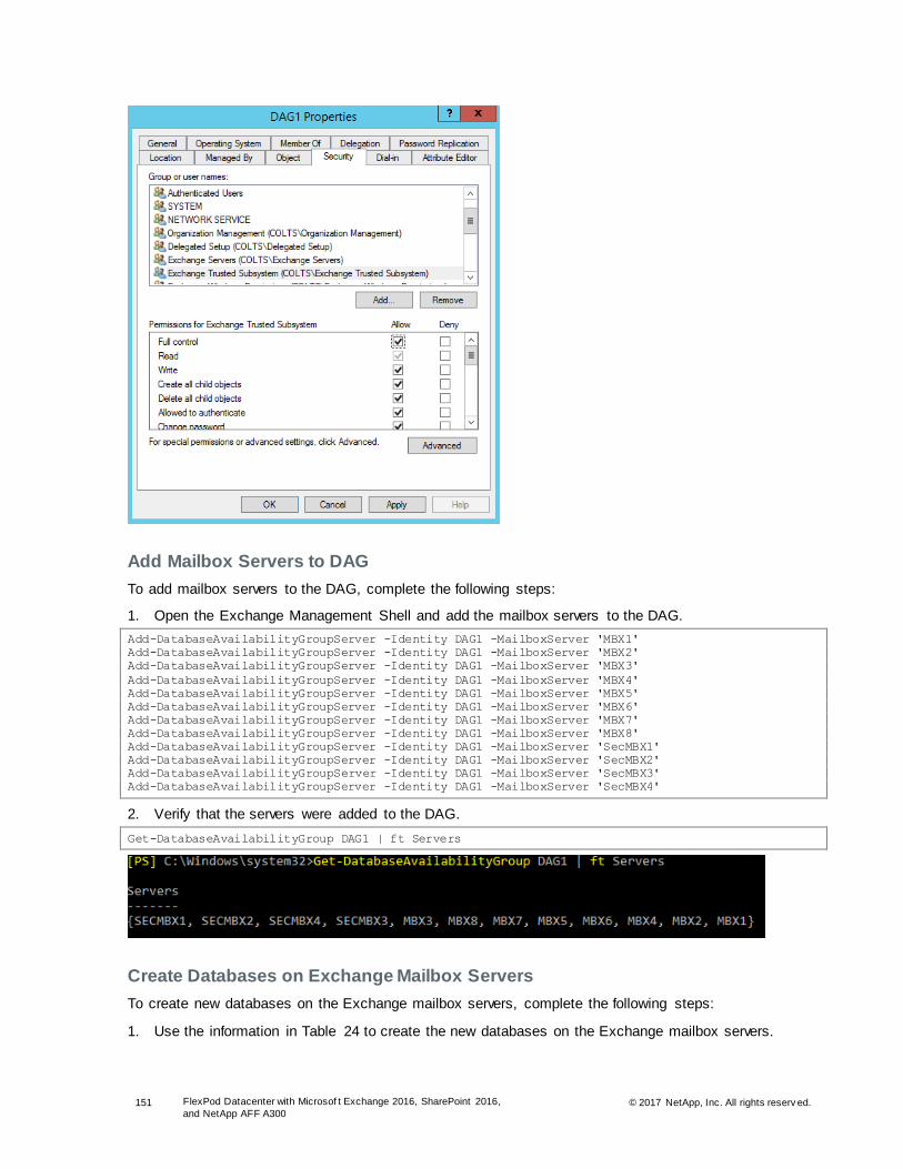
151 FlexPod Datacenter with Microsof t Exchange 2016, SharePoint 2016,
and NetApp AFF A300 © 2017 NetApp, Inc. All rights reserv ed.
Add Mailbox Servers to DAG
To add mailbox servers to the DAG, complete the following steps:
1. Open the Exchange Management Shell and add the mailbox servers to the DAG.
Add-DatabaseAvailabilityGroupServer -Identity DAG1 -MailboxServer 'MBX1'
Add-DatabaseAvailabilityGroupServer -Identity DAG1 -MailboxServer 'MBX2'
Add-DatabaseAvailabilityGroupServer -Identity DAG1 -MailboxServer 'MBX3'
Add-DatabaseAvailabilityGroupServer -Identity DAG1 -MailboxServer 'MBX4'
Add-DatabaseAvailabilityGroupServer -Identity DAG1 -MailboxServer 'MBX5'
Add-DatabaseAvailabilityGroupServer -Identity DAG1 -MailboxServer 'MBX6'
Add-DatabaseAvailabilityGroupServer -Identity DAG1 -MailboxServer 'MBX7'
Add-DatabaseAvailabilityGroupServer -Identity DAG1 -MailboxServer 'MBX8'
Add-DatabaseAvailabilityGroupServer -Identity DAG1 -MailboxServer 'SecMBX1'
Add-DatabaseAvailabilityGroupServer -Identity DAG1 -MailboxServer 'SecMBX2'
Add-DatabaseAvailabilityGroupServer -Identity DAG1 -MailboxServer 'SecMBX3'
Add-DatabaseAvailabilityGroupServer -Identity DAG1 -MailboxServer 'SecMBX4'
2. Verify that the servers were added to the DAG.
Get-DatabaseAvailabilityGroup DAG1 | ft Servers
Create Databases on Exchange Mailbox Servers
To create new databases on the Exchange mailbox servers, complete the following steps:
1. Use the information in Table 24 to create the new databases on the Exchange mailbox servers.

152 FlexPod Datacenter with Microsof t Exchange 2016, SharePoint 2016,
and NetApp AFF A300 © 2017 NetApp, Inc. All rights reserv ed.
Table 24) Databases on Exchange mailbox servers.
Database Name Server EDB File Path Log Folder Path
DAG1-DB01 MBX01 C:\db\DB01\DB01.edb C:\log\DB01
DAG1-DB02 MBX02 C:\db\DB02\DB02.edb C:\log\DB02
DAG1-DB03 MBX03 C:\db\DB03\DB03.edb C:\log\DB03
DAG1-DB04 MBX04 C:\db\DB04\DB04.edb C:\log\DB04
DAG1-DB05 MBX05 C:\db\DB05\DB05.edb C:\log\DB05
DAG1-DB06 MBX06 C:\db\DB06\DB06.edb C:\log\DB06
DAG1-DB07 MBX07 C:\db\DB07\DB07.edb C:\log\DB07
DAG1-DB08 MBX08 C:\db\DB08\DB08.edb C:\log\DB08
DAG1-DB09 MBX01 C:\db\DB09\DB09.edb C:\log\DB09
DAG1-DB10 MBX02 C:\db\DB10\DB10.edb C:\log\DB10
DAG1-DB11 MBX03 C:\db\DB11\DB11.edb C:\log\DB11
DAG1-DB12 MBX04 C:\db\DB12\DB12.edb C:\log\DB12
DAG1-DB13 MBX05 C:\db\DB13\DB13.edb C:\log\DB13
DAG1-DB14 MBX06 C:\db\DB14\DB14.edb C:\log\DB14
DAG1-DB15 MBX07 C:\db\DB15\DB15.edb C:\log\DB15
DAG1-DB16 MBX08 C:\db\DB16\DB16.edb C:\log\DB16
DAG1-DB17 MBX01 C:\db\DB17\DB17.edb C:\log\DB17
DAG1-DB18 MBX02 C:\db\DB18\DB18.edb C:\log\DB18
DAG1-DB19 MBX03 C:\db\DB19\DB19.edb C:\log\DB19
DAG1-DB20 MBX04 C:\db\DB20\DB20.edb C:\log\DB20
DAG1-DB21 MBX05 C:\db\DB21\DB21.edb C:\log\DB21
DAG1-DB22 MBX06 C:\db\DB22\DB22.edb C:\log\DB22
DAG1-DB23 MBX07 C:\db\DB23\DB23.edb C:\log\DB23
DAG1-DB24 MBX08 C:\db\DB24\DB24.edb C:\log\DB24
DAG1-DB25 MBX01 C:\db\DB25\DB25.edb C:\log\DB25
DAG1-DB26 MBX02 C:\db\DB26\DB26.edb C:\log\DB26
DAG1-DB27 MBX03 C:\db\DB27\DB27.edb C:\log\DB27
DAG1-DB28 MBX04 C:\db\DB28\DB28.edb C:\log\DB28
DAG1-DB29 MBX01 C:\db\DB29\DB29.edb C:\log\DB29
DAG1-DB30 MBX02 C:\db\DB30\DB30.edb C:\log\DB30
DAG1-DB31 MBX03 C:\db\DB31\DB31.edb C:\log\DB31

153 FlexPod Datacenter with Microsof t Exchange 2016, SharePoint 2016,
and NetApp AFF A300 © 2017 NetApp, Inc. All rights reserv ed.
Database Name Server EDB File Path Log Folder Path
DAG1-DB32 MBX04 C:\db\DB32\DB32.edb C:\log\DB32
2. Create the new databases.
New-MailboxDatabase -Server MBX01 -Name DAG1-DB01 -Edb C:\db\DB01\DB01.edb -Log C:\log\DB01
New-MailboxDatabase -Server MBX02 -Name DAG1-DB02 -Edb C:\db\DB02\DB02.edb -Log C:\log\DB02
New-MailboxDatabase -Server MBX03 -Name DAG1-DB03 -Edb C:\db\DB03\DB03.edb -Log C:\log\DB03
New-MailboxDatabase -Server MBX04 -Name DAG1-DB04 -Edb C:\db\DB04\DB04.edb -Log C:\log\DB04
New-MailboxDatabase -Server MBX05 -Name DAG1-DB05 -Edb C:\db\DB05\DB05.edb -Log C:\log\DB05
New-MailboxDatabase -Server MBX06 -Name DAG1-DB06 -Edb C:\db\DB06\DB06.edb -Log C:\log\DB06
New-MailboxDatabase -Server MBX07 -Name DAG1-DB07 -Edb C:\db\DB07\DB07.edb -Log C:\log\DB07
New-MailboxDatabase -Server MBX08 -Name DAG1-DB08 -Edb C:\db\DB08\DB08.edb -Log C:\log\DB08
New-MailboxDatabase -Server MBX01 -Name DAG1-DB09 -Edb C:\db\DB09\DB09.edb -Log C:\log\DB09
New-MailboxDatabase -Server MBX02 -Name DAG1-DB10 -Edb C:\db\DB10\DB10.edb -Log C:\log\DB10
New-MailboxDatabase -Server MBX03 -Name DAG1-DB11 -Edb C:\db\DB11\DB11.edb -Log C:\log\DB11
New-MailboxDatabase -Server MBX04 -Name DAG1-DB12 -Edb C:\db\DB12\DB12.edb -Log C:\log\DB12
New-MailboxDatabase -Server MBX05 -Name DAG1-DB13 -Edb C:\db\DB13\DB13.edb -Log C:\log\DB13
New-MailboxDatabase -Server MBX06 -Name DAG1-DB14 -Edb C:\db\DB14\DB14.edb -Log C:\log\DB14
New-MailboxDatabase -Server MBX07 -Name DAG1-DB15 -Edb C:\db\DB15\DB15.edb -Log C:\log\DB15
New-MailboxDatabase -Server MBX08 -Name DAG1-DB16 -Edb C:\db\DB16\DB16.edb -Log C:\log\DB16
New-MailboxDatabase -Server MBX01 -Name DAG1-DB17 -Edb C:\db\DB17\DB17.edb -Log C:\log\DB17
New-MailboxDatabase -Server MBX02 -Name DAG1-DB18 -Edb C:\db\DB18\DB18.edb -Log C:\log\DB18
New-MailboxDatabase -Server MBX03 -Name DAG1-DB19 -Edb C:\db\DB19\DB19.edb -Log C:\log\DB19
New-MailboxDatabase -Server MBX04 -Name DAG1-DB20 -Edb C:\db\DB20\DB20.edb -Log C:\log\DB20
New-MailboxDatabase -Server MBX05 -Name DAG1-DB21 -Edb C:\db\DB21\DB21.edb -Log C:\log\DB21
New-MailboxDatabase -Server MBX06 -Name DAG1-DB22 -Edb C:\db\DB22\DB22.edb -Log C:\log\DB22
New-MailboxDatabase -Server MBX07 -Name DAG1-DB23 -Edb C:\db\DB23\DB23.edb -Log C:\log\DB23
New-MailboxDatabase -Server MBX08 -Name DAG1-DB24 -Edb C:\db\DB24\DB24.edb -Log C:\log\DB24
New-MailboxDatabase -Server MBX01 -Name DAG1-DB25 -Edb C:\db\DB25\DB25.edb -Log C:\log\DB25
New-MailboxDatabase -Server MBX02 -Name DAG1-DB26 -Edb C:\db\DB26\DB26.edb -Log C:\log\DB26
New-MailboxDatabase -Server MBX03 -Name DAG1-DB27 -Edb C:\db\DB27\DB27.edb -Log C:\log\DB27
New-MailboxDatabase -Server MBX04 -Name DAG1-DB28 -Edb C:\db\DB28\DB28.edb -Log C:\log\DB28
New-MailboxDatabase -Server MBX05 -Name DAG1-DB29 -Edb C:\db\DB29\DB29.edb -Log C:\log\DB29
New-MailboxDatabase -Server MBX06 -Name DAG1-DB30 -Edb C:\db\DB30\DB30.edb -Log C:\log\DB30
New-MailboxDatabase -Server MBX07 -Name DAG1-DB31 -Edb C:\db\DB31\DB31.edb -Log C:\log\DB31
New-MailboxDatabase -Server MBX08 -Name DAG1-DB32 -Edb C:\db\DB32\DB32.edb -Log C:\log\DB32
3. Restart the Microsoft Exchange Information Store on each Exchange server after creating each
database. Run the following command from the PowerShell Console on each Exchange server:
Restart-Service MSExchangeIS
4. Verify the Exchange database configuration.
Get-MailboxDatabase
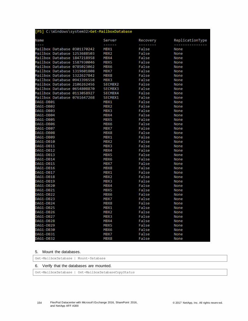
154 FlexPod Datacenter with Microsof t Exchange 2016, SharePoint 2016,
and NetApp AFF A300 © 2017 NetApp, Inc. All rights reserv ed.
5. Mount the databases.
Get-MailboxDatabase | Mount-Database
6. Verify that the databases are mounted.
Get-MailboxDatabase | Get-MailboxDatabaseCopyStatus
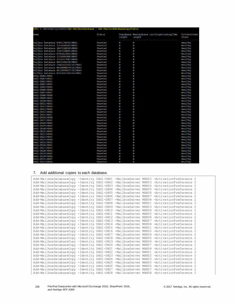
155 FlexPod Datacenter with Microsof t Exchange 2016, SharePoint 2016,
and NetApp AFF A300 © 2017 NetApp, Inc. All rights reserv ed.
7. Add additional copies to each database.
Add-MailboxDatabaseCopy -Identity DAG1-DB01 -MailboxServer MBX02 -ActivationPreference 2
Add-MailboxDatabaseCopy -Identity DAG1-DB02 -MailboxServer MBX03 -ActivationPreference 2
Add-MailboxDatabaseCopy -Identity DAG1-DB03 -MailboxServer MBX04 -ActivationPreference 2
Add-MailboxDatabaseCopy -Identity DAG1-DB04 -MailboxServer MBX05 -ActivationPreference 2
Add-MailboxDatabaseCopy -Identity DAG1-DB05 -MailboxServer MBX06 -ActivationPreference 2
Add-MailboxDatabaseCopy -Identity DAG1-DB06 -MailboxServer MBX07 -ActivationPreference 2
Add-MailboxDatabaseCopy -Identity DAG1-DB07 -MailboxServer MBX08 -ActivationPreference 2
Add-MailboxDatabaseCopy -Identity DAG1-DB08 -MailboxServer MBX01 -ActivationPreference 2
Add-MailboxDatabaseCopy -Identity DAG1-DB09 -MailboxServer MBX03 -ActivationPreference 2
Add-MailboxDatabaseCopy -Identity DAG1-DB10 -MailboxServer MBX04 -ActivationPreference 2
Add-MailboxDatabaseCopy -Identity DAG1-DB11 -MailboxServer MBX05 -ActivationPreference 2
Add-MailboxDatabaseCopy -Identity DAG1-DB12 -MailboxServer MBX06 -ActivationPreference 2
Add-MailboxDatabaseCopy -Identity DAG1-DB13 -MailboxServer MBX07 -ActivationPreference 2
Add-MailboxDatabaseCopy -Identity DAG1-DB14 -MailboxServer MBX08 -ActivationPreference 2
Add-MailboxDatabaseCopy -Identity DAG1-DB15 -MailboxServer MBX01 -ActivationPreference 2
Add-MailboxDatabaseCopy -Identity DAG1-DB16 -MailboxServer MBX02 -ActivationPreference 2
Add-MailboxDatabaseCopy -Identity DAG1-DB17 -MailboxServer MBX04 -ActivationPreference 2
Add-MailboxDatabaseCopy -Identity DAG1-DB18 -MailboxServer MBX05 -ActivationPreference 2
Add-MailboxDatabaseCopy -Identity DAG1-DB19 -MailboxServer MBX06 -ActivationPreference 2
Add-MailboxDatabaseCopy -Identity DAG1-DB20 -MailboxServer MBX07 -ActivationPreference 2
Add-MailboxDatabaseCopy -Identity DAG1-DB21 -MailboxServer MBX08 -ActivationPreference 2
Add-MailboxDatabaseCopy -Identity DAG1-DB22 -MailboxServer MBX01 -ActivationPreference 2
Add-MailboxDatabaseCopy -Identity DAG1-DB23 -MailboxServer MBX02 -ActivationPreference 2
Add-MailboxDatabaseCopy -Identity DAG1-DB24 -MailboxServer MBX03 -ActivationPreference 2
Add-MailboxDatabaseCopy -Identity DAG1-DB25 -MailboxServer MBX05 -ActivationPreference 2
Add-MailboxDatabaseCopy -Identity DAG1-DB26 -MailboxServer MBX06 -ActivationPreference 2
Add-MailboxDatabaseCopy -Identity DAG1-DB27 -MailboxServer MBX07 -ActivationPreference 2
Add-MailboxDatabaseCopy -Identity DAG1-DB28 -MailboxServer MBX08 -ActivationPreference 2

156 FlexPod Datacenter with Microsof t Exchange 2016, SharePoint 2016,
and NetApp AFF A300 © 2017 NetApp, Inc. All rights reserv ed.
Add-MailboxDatabaseCopy -Identity DAG1-DB29 -MailboxServer MBX01 -ActivationPreference 2
Add-MailboxDatabaseCopy -Identity DAG1-DB30 -MailboxServer MBX02 -ActivationPreference 2
Add-MailboxDatabaseCopy -Identity DAG1-DB31 -MailboxServer MBX03 -ActivationPreference 2
Add-MailboxDatabaseCopy -Identity DAG1-DB32 -MailboxServer MBX04 -ActivationPreference 2
Note: Repeat for any additional copies as needed.
Add-MailboxDatabaseCopy -Identity DAG1-DB01 -MailboxServer SecMbx01 -ActivationPreference 3
Add-MailboxDatabaseCopy -Identity DAG1-DB02 -MailboxServer SecMbx02 -ActivationPreference 3
Add-MailboxDatabaseCopy -Identity DAG1-DB03 -MailboxServer SecMbx03 -ActivationPreference 3
Add-MailboxDatabaseCopy -Identity DAG1-DB04 -MailboxServer SecMbx04 -ActivationPreference 3
Add-MailboxDatabaseCopy -Identity DAG1-DB05 -MailboxServer SecMbx01 -ActivationPreference 3
Add-MailboxDatabaseCopy -Identity DAG1-DB06 -MailboxServer SecMbx02 -ActivationPreference 3
Add-MailboxDatabaseCopy -Identity DAG1-DB07 -MailboxServer SecMbx03 -ActivationPreference 3
Add-MailboxDatabaseCopy -Identity DAG1-DB08 -MailboxServer SecMbx04 -ActivationPreference 3
Add-MailboxDatabaseCopy -Identity DAG1-DB09 -MailboxServer SecMbx01 -ActivationPreference 3
Add-MailboxDatabaseCopy -Identity DAG1-DB10 -MailboxServer SecMbx02 -ActivationPreference 3
Add-MailboxDatabaseCopy -Identity DAG1-DB11 -MailboxServer SecMbx03 -ActivationPreference 3
Add-MailboxDatabaseCopy -Identity DAG1-DB12 -MailboxServer SecMbx04 -ActivationPreference 3
Add-MailboxDatabaseCopy -Identity DAG1-DB13 -MailboxServer SecMbx01 -ActivationPreference 3
Add-MailboxDatabaseCopy -Identity DAG1-DB14 -MailboxServer SecMbx02 -ActivationPreference 3
Add-MailboxDatabaseCopy -Identity DAG1-DB15 -MailboxServer SecMbx03 -ActivationPreference 3
Add-MailboxDatabaseCopy -Identity DAG1-DB16 -MailboxServer SecMbx04 -ActivationPreference 3
Add-MailboxDatabaseCopy -Identity DAG1-DB17 -MailboxServer SecMbx01 -ActivationPreference 3
Add-MailboxDatabaseCopy -Identity DAG1-DB18 -MailboxServer SecMbx02 -ActivationPreference 3
Add-MailboxDatabaseCopy -Identity DAG1-DB19 -MailboxServer SecMbx03 -ActivationPreference 3
Add-MailboxDatabaseCopy -Identity DAG1-DB20 -MailboxServer SecMbx04 -ActivationPreference 3
Add-MailboxDatabaseCopy -Identity DAG1-DB21 -MailboxServer SecMbx01 -ActivationPreference 3
Add-MailboxDatabaseCopy -Identity DAG1-DB22 -MailboxServer SecMbx02 -ActivationPreference 3
Add-MailboxDatabaseCopy -Identity DAG1-DB23 -MailboxServer SecMbx03 -ActivationPreference 3
Add-MailboxDatabaseCopy -Identity DAG1-DB24 -MailboxServer SecMbx04 -ActivationPreference 3
Add-MailboxDatabaseCopy -Identity DAG1-DB25 -MailboxServer SecMbx01 -ActivationPreference 3
Add-MailboxDatabaseCopy -Identity DAG1-DB26 -MailboxServer SecMbx02 -ActivationPreference 3
Add-MailboxDatabaseCopy -Identity DAG1-DB27 -MailboxServer SecMbx03 -ActivationPreference 3
Add-MailboxDatabaseCopy -Identity DAG1-DB28 -MailboxServer SecMbx04 -ActivationPreference 3
Add-MailboxDatabaseCopy -Identity DAG1-DB29 -MailboxServer SecMbx01 -ActivationPreference 3
Add-MailboxDatabaseCopy -Identity DAG1-DB30 -MailboxServer SecMbx02 -ActivationPreference 3
Add-MailboxDatabaseCopy -Identity DAG1-DB31 -MailboxServer SecMbx03 -ActivationPreference 3
Add-MailboxDatabaseCopy -Identity DAG1-DB32 -MailboxServer SecMbx04 -ActivationPreference 3
8. Enable database circular logging.
Get-MailboxDatabase | Set-MailboxDatabase -CircularLoggingEnabled $true
9. Mount databases.
Get-MailboxDatabase | Mount-Database
10. Verify that the databases are created.
Get-MailboxDatabase | ft Server,Name,DatabaseCreated
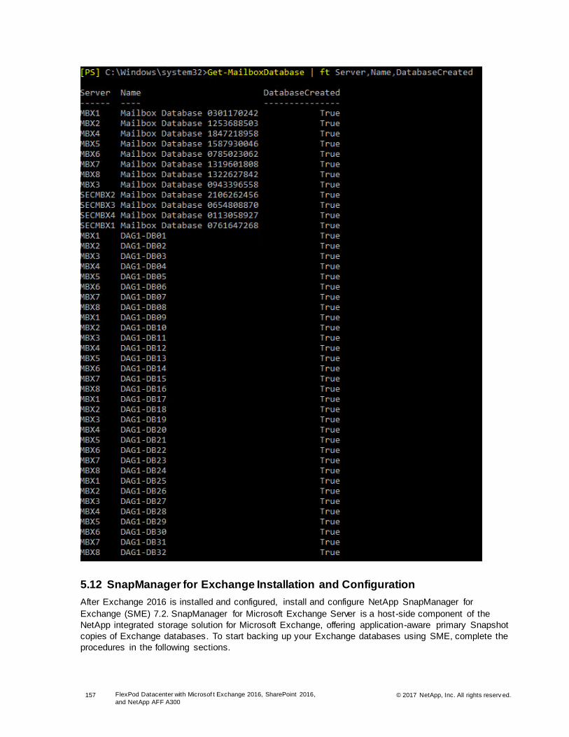
157 FlexPod Datacenter with Microsof t Exchange 2016, SharePoint 2016,
and NetApp AFF A300 © 2017 NetApp, Inc. All rights reserv ed.
5.12 SnapManager for Exchange Installation and Configuration
After Exchange 2016 is installed and configured, install and configure NetApp SnapManager for
Exchange (SME) 7.2. SnapManager for Microsoft Exchange Server is a host-side component of the
NetApp integrated storage solution for Microsoft Exchange, offering application-aware primary Snapshot
copies of Exchange databases. To start backing up your Exchange databases using SME, complete the
procedures in the following sections.
158 FlexPod Datacenter with Microsof t Exchange 2016, SharePoint 2016,
and NetApp AFF A300 © 2017 NetApp, Inc. All rights reserv ed.
Configure Service Accounts
The SnapManager service account that is required for SME to work properly must be configured using
the following step:
1. Add the SME-SVC domain user to the Exchange Server Management Role Group.
Install SnapManager
To install SnapManager, complete the following steps:
1. Download the latest SME installer from the NetApp Support site.
2. Double-click the downloaded .exe file.
3. On the Welcome page, click Next.
4. Enter the user name and organization details, select the Per Storage System license type, and click
Next.
5. Browse to the location where you want to install SnapManager and click Next.
6. Enter the SME-SVC account details and click Next.
7. Click Install.
8. Click Finish when the installation is done to close the wizard.
9. Repeat steps 1 through 8 for each mailbox server in your Exchange environment.
Configure Windows Firewall
To enable SnapManager communications and for DAG support, create the following firewall rules on all
the mailbox servers:
1. Create an inbound rule that allows the SnapManager service to communicate.
$splat = @{
Action = 'allow'
Direction = 'Inbound'
DisplayName = 'SnapManager for Exchange'
Program = 'C:\Program Files\NetApp\SnapManager for Exchange\SnapMgrService.exe'
}
New-NetFirewallRule @Splat
New-NetFirewallRule -DisplayName "SME 810" –Protocol TCP –LocalPort 810 -Action Allow
Connect SnapManager to Exchange Servers
Connect to the Exchange servers from SnapManager and then complete the configuration wizard by
completing the following steps:
1. From the Windows Start menu, click SnapManager for Exchange. The SnapManager console opens ,
and a message informs you that you need to specify an Exchange server.
2. Click OK. The Add Exchange Server to be Managed dialog box is displayed.
3. To select a server, double-click one in the list or click Browse.
Note: In this example, because DAG was used, we connected to each DAG member and then connected to the DAG.
4. After selecting a server, click Add. SnapManager connects to the server and then displays a message
informing you that SnapManager for Exchange is not configured on the Exchange server.
5. Click OK. The Configuration wizard is displayed.
6. Click Next in the SME Configuration wizard.
7. Select the Select a Verification Server Later Using the Options Menu option and click Next.

159 FlexPod Datacenter with Microsof t Exchange 2016, SharePoint 2016,
and NetApp AFF A300 © 2017 NetApp, Inc. All rights reserv ed.
8. Click Next.
9. The correct database layout was used during the Exchange installation; therefore, you do not need to
migrate storage to LUNs. Click Next.
10. On the Select a Set of Logs page, click Next.
11. Verify the SnapInfo directory destinations. The SnapInfo directories should coexist on the log LUNs.
Click Next.
12. On the Configure Dataset page, click Next.
13. Select the Yes, Add the Microsoft iSCSI Service as a Dependency for Exchange System Attendant
Service option and click Next.
14. Configure the appropriate notification settings on the AutoSupport Settings page and click Next.
15. Configure the appropriate monitoring and reporting settings and click Next.
16. Click Finish.
17. Review the configuration tasks and click Start Now.
18. Click OK in the successful completion message and click Close.
19. Repeat steps 1 through 18 for all of the mailbox servers.
20. After all of the mailbox servers have been added on the primary and secondary stacks, follow the instructions for how you can create backup and restore jobs for the DAG in the SnapManager 7.2 for
Microsoft Exchange Server Installation Guide.
Install Single Mailbox Recovery
NetApp Single Mailbox Recovery (SMBR) works with your existing Microsoft Exchange Server backup
architecture and procedures and allows you to recover individual mailboxes, folders, messages,
attachments, and even calendars, notes, and tasks directly to your production Microsoft Exchange Server
or any PST file. To install NetApp SMBR, complete the following steps:
1. Before you start with the installation, make sure that the VM on which you are installing SMBR meets
the following prerequisites:
a. .NET Framework 3.5 SP1 and .NET Framework 4.0
b. NetApp SnapDrive
c. Microsoft Office Outlook 2007 and later (32-bit versions only)
d. Microsoft Exchange Management Tools
\\mailbox1\C$\E2016U6\Setup.EXE" /role:managementtools /IAcceptExchangeServerLicenseTerms
/installwindowscomponents
e. NetApp SnapManager for Exchange 7.2
"SME7.2P2_x64.exe" /s /v"/qb+ SILENT_MODE=1 SVCUSERNAME=<<Domain Name>>\<<SME-SVC Account>>
SVCUSERPASSWORD=<<password>> SVCCONFIRMUSERPASSWORD=<<password>> /L*V C:\SME_Install.log"
2. Download the latest copy of NetApp Single Mailbox Recovery from the NetApp Support site.
3. Double-click SMBR72.exe to start the installation.
4. Click Install to install the Microsoft Visual C++ prerequisites.
5. Click Next.
6. Enter the user name and company name and click Next.
7. Browse to the installation destination folder and click Next.
8. Select both features listed on the page and click Next.

160 FlexPod Datacenter with Microsof t Exchange 2016, SharePoint 2016,
and NetApp AFF A300 © 2017 NetApp, Inc. All rights reserv ed.
9. When the installation is complete, click Finish.
6 Solution Verification
6.1 Exchange 2016 Verification
Exchange 2016 was verified by using Microsoft Exchange Load Generator 2013 (LoadGen) because it
tested all aspects of Exchange. Jet Stress was run during the installation to prevalidate the storage
configuration.
Microsoft Exchange LoadGen 2013 Verification
Eight workload generation hosts were deployed in a separate load generation cluster. While it was not
mandatory, the workload was run from a dedicated cluster to capture pure workload performance
characteristics. Each LoadGen host was given four Exchange databases and 1,252 users to validate.
Each user was configured by using the Exchange 2007 cached client to perform 150 actions against a
2GB mailbox, as seen in Figure 5.

161 FlexPod Datacenter with Microsof t Exchange 2016, SharePoint 2016,
and NetApp AFF A300 © 2017 NetApp, Inc. All rights reserv ed.
Figure 5) Exchange LoadGen 2013 configuration summary.
All eight LoadGen hosts were run in parallel with the SharePoint workload. The results are shown in
Figure 6 through Figure 13.
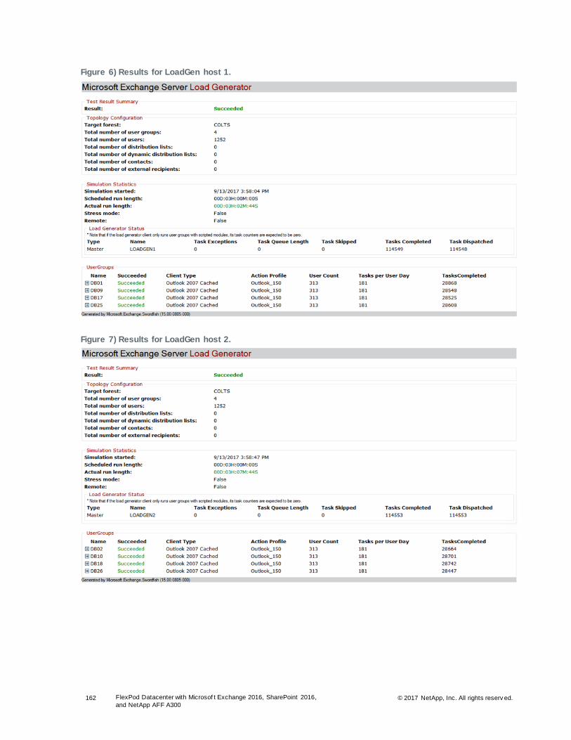
162 FlexPod Datacenter with Microsof t Exchange 2016, SharePoint 2016,
and NetApp AFF A300 © 2017 NetApp, Inc. All rights reserv ed.
Figure 6) Results for LoadGen host 1.
Figure 7) Results for LoadGen host 2.

163 FlexPod Datacenter with Microsof t Exchange 2016, SharePoint 2016,
and NetApp AFF A300 © 2017 NetApp, Inc. All rights reserv ed.
Figure 8) Results for LoadGen host 3.
Figure 9) Results for LoadGen host 4.

164 FlexPod Datacenter with Microsof t Exchange 2016, SharePoint 2016,
and NetApp AFF A300 © 2017 NetApp, Inc. All rights reserv ed.
Figure 10) Results for LoadGen host 5.
Figure 11) Results for LoadGen host 6.

165 FlexPod Datacenter with Microsof t Exchange 2016, SharePoint 2016,
and NetApp AFF A300 © 2017 NetApp, Inc. All rights reserv ed.
Figure 12) Results for LoadGen host 7.
Figure 13) Results for LoadGen host 8.
Performance Results and Analysis
Depending on the complexity of the deployment and user activity, Exchange 2016 server performance
varies between environments, as shown in Table 25.

166 FlexPod Datacenter with Microsof t Exchange 2016, SharePoint 2016,
and NetApp AFF A300 © 2017 NetApp, Inc. All rights reserv ed.
Table 25) Exchange performance results. .
Counter MBX1 MBX2 MBX3 MBX4 MBX5 MBX6 MBX7 MBX8
MSExchange RpcClientAccess\Active User Count
869 866 860 866 856 862 860 859
MSExchange RpcClientAccess\User Count
1,050 1,062 1,062 1,066 1,050 1,063 1,068 1,065
MSExchangeIS Store\Messages
Delived/Sec 4.3 4.3 4.3 4.4 4.3 4.3 4.3 4.3
MSExchangeIS Store\Messages
Submitted/Sec 1.1 1.1 1.1 1.1 1.1 1.1 1.1 1.1
MSExchange ADAccess Domain Controllers(AD1)\LDAP Read Time
1.2 1 0.9 1 1.1 1 0.9 0.9
MSExchange ADAccess Domain Controllers(AD1)\LDAP Search Time
1.1 1.2 1.2 1.3 1.3 1.4 1.3 1.3
MSExchange ADAccess Domain Controllers(AD2)\LDAP Read Time
1.4 1.6 1.6 1.8 1.4 1.6 1.8 1.7
MSExchange ADAccess Domain Controllers(AD2)\LDAP Search Time
1.2 1.3 1.4 1.5 1.5 1.4 1.4 1.7
MSExchangeIS Client Type(*)\RPC Average Latency
0.3 0.3 0.4 0.4 0.4 0.4 0.5 0.4
NET CLR Memory(_Global_)\% Time in GC
0.9 1 1 0.9 1.2 0.9 1.1 1
Processor Utilization
Figure 14 is a graph that shows the percentage of CPU utilization for the mailbox servers.
Figure 14) Processor utilization.
Memory Utilization
Figure 15 is a graph that shows the percentage of memory utilization for the mailbox servers.

167 FlexPod Datacenter with Microsof t Exchange 2016, SharePoint 2016,
and NetApp AFF A300 © 2017 NetApp, Inc. All rights reserv ed.
Figure 15) Memory utilization.
6.2 SharePoint 2016 Verification
The physical architecture of the test farm consists of 10 Visual Studio Team System (VSTS) 2008
controllers. Servers and the network infrastructures, which together create the SharePoint environment,
are tailored with respect to the size and topology, as explained in the subsequent sections.
Modeling a SharePoint Server 2016 environment begins with analyzing the current requirements and
estimating the expected future demand and targets for the deployment. Decisions are made about the
key solution that an environment must support and establishment of all of the important metrics and
parameters. The SharePoint Server 2016 environment is modeled with consideration to enterprise
workload characteristics such as the number of users, most frequently used operations, and datasets
such as content size and content distribution demands and is tailored in accordance with Microsoft
recommendations.
Workload Characteristics
Sizing a SharePoint environment workload is a factor in the solution. The system under test should
sustain the described workload demands, user base, and usage characteristics. Table 26 lists these
workload characteristics.
Table 26) Workload characteristics.
Workload Characteristics Value
Number of users (unique users in a 24-hour period) 10,000
Concurrent users at peak time (distinct users generating requests in a given time frame)
10,000
Percentage of browse operations 30%
Percentage of open operations 30%
Percentage of search operations 30%
Percentage of upload operations 10%
Workload Mix (100 RPH)
SharePoint farm requirements include the number of users and their usage characteristics. The
performance test considered a heavy profile: a single active user made 100 different requests per hour to
the SharePoint 2016 farm. One hundred requests per hour per user were considered for this test case.

168 FlexPod Datacenter with Microsof t Exchange 2016, SharePoint 2016,
and NetApp AFF A300 © 2017 NetApp, Inc. All rights reserv ed.
User activities or usage characteristics were modeled based on the enterprise business environment
needs: for example, from organizations such as marketing, engineering, and so on. In general, the
environment hosts central team sites; publishing portals for internal teams; and enterprise collaboration of
organizations, teams, and projects. Sites created in these environments were used as communication
portals, host applications for business solutions, and channels for general collaboration. Searching,
editing, and uploading documents; participating in discussions; posting and commenting on blogs; and so
on were among the most common activities.
Performance Test Framework
The performance test provided the responsiveness, throughput, reliability, and scalability of a SharePoint
2016 farm under a given workload. The results of the performance test and analysis can help you
estimate the hardware configuration required for a SharePoint 2016 farm to support 10,000 users under
production operation in a FlexPod solution.
Test Methodology
In this solution, we used Microsoft VSTS in conjunction with the custom code to simulate real-world
SharePoint user activity. Validating the performance of the SharePoint 2016 farm with the associated
tools (VSTS, bulk loader) was a complex activity and is not required for every deployment.
NetApp recommends that you perform validation testing when custom code for the SharePoint 2016 farm
is available.
The 2TB content database that was created has sites, site collections, and other important features that
constitute the dataset.
HTTP Throttling
HTTP throttling is a SharePoint 2016 feature that allows the server to discard the server requests when it
is too busy. Every five seconds, a dedicated job runs and checks the server resources to compare with
the resource levels configured for the server. By default, the server CPU, memory, request in queue, and
request wait time are being monitored. The server enters a throttling period after three consecutive
unsuccessful HTTP GET checks. The server remains in this period until a successful check is done.
Requests generated before the server enters the throttling mode are accepted and completed. Any new
HTTP GET request or Search Robot request generates a 503 error message and is logged in the event
viewer. Also, while the server is in a throttling period, no new timer jobs can be get started.
To monitor the server performance, the HTTP throttling is turned off, as shown in Figure 16.
Figure 16) HTTP throttling: off mode.

169 FlexPod Datacenter with Microsof t Exchange 2016, SharePoint 2016,
and NetApp AFF A300 © 2017 NetApp, Inc. All rights reserv ed.
Performance Results and Analysis
Depending on the complexity of the deployment and the components involved in the architecture,
SharePoint 2016 server performance varies between environments. Performance of the SharePoint
architecture is determined by the user experience.
The following major performance counters measure user experience:
• Requests per second: number of requests per second taken by the SharePoint server
• Average response time: amount of time the SharePoint server takes to return the results of a
request to the user
• Average page response time: average time to download the page and all its dependent requests
such as images, css, js, and so on
Table 21 shows the results for the applied workload (100 RPH) on the created SharePoint farm.
Table 27) Applied workload (100 RPH) on the created SharePoint farm.
Load Server
Number User Count Average Requests
per Second
Average Response
Time (Sec)
Average Page
Time (Sec)
1 1,000 28.3 0.47 0.52
2 1,000 28.2 0.48 0.53
3 1,000 28.2 0.48 0.53
4 1,000 28.2 0.49 0.54
5 1,000 28.2 0.49 0.53
6 1,000 28.2 0.49 0.54
7 1,000 28.3 0.48 0.53
8 1,000 28.3 0.49 0.54
9 1,000 28.3 0.49 0.54
10 1,000 28.2 0.49 0.53
Table 27 shows how you can easily support more than 10,000 active SharePoint users with subsecond
response times.
Processor Utilization
This section contains graphs that show the percentage of CPU utilization for the different components in
the SharePoint 2016 farm.
Web Front-End Server
The graph in Figure 17 shows the CPU utilization of the SharePoint web front-end servers. Under a heavy
workload of 10,000 users, virtual servers are hosted on Cisco UCS B200 M4 servers. CPU utilization
remained at around 35% to 40% on an average. The graph shows the linear growth in the CPU utilization
for the increase in the user load and their workloads. The graph shows the virtual server on Cisco UCS
B200 M4 server’s capacity to accommodate more workloads with ease without causing any stress.

170 FlexPod Datacenter with Microsof t Exchange 2016, SharePoint 2016,
and NetApp AFF A300 © 2017 NetApp, Inc. All rights reserv ed.
Figure 17) SharePoint web front-end processor utilization.
Application and Search Servers
The graphs in Figure 18 and Figure 19 show the CPU utilization of the SharePoint application and search
servers. Under a heavy load of 10,000 active users, the servers are not under heavy utilization. This
implies that more than 10,000 active users can be easily supported, or a component failure in the farm
can be easily sustained.
Figure 18) SharePoint application server processor utilization.

171 FlexPod Datacenter with Microsof t Exchange 2016, SharePoint 2016,
and NetApp AFF A300 © 2017 NetApp, Inc. All rights reserv ed.
Figure 19) SharePoint search server processor utilization.
Database Server
The graph in Figure 20 shows the SQL Server 2016 database server CPU utilization. On average, the
overall CPU utilization at the database tier with virtual servers remained at around 35% (when the server
was hosted on the Cisco UCS B200 M4). FlexPod accommodated more CPU utilization without causing
stress on its performance. Also, as shown in this graph, only the active SQL Server was under 35%
utilization; the remaining servers were at 5% to 10% utilization.
Figure 20) SQL Server processor utilization.
Network Utilization
The graph in Figure 21 shows the network utilization at the web front-end application and search servers
of the SharePoint 2016 large farm. This graph also shows the aggregated performance numbers of the
network utilization on all of the servers in the farm.

172 FlexPod Datacenter with Microsof t Exchange 2016, SharePoint 2016,
and NetApp AFF A300 © 2017 NetApp, Inc. All rights reserv ed.
Figure 21) Network utilization.
Memory Utilization
The graph in Figure 22 shows the memory utilization of the SharePoint 2016 server farm under workloads
of 10,000 users.
Figure 22) Memory utilization.
The maximum memory utilization on the web front-end server's application server and SQL Server at the
maximum user load is within 50% of the available physical memory. This utilization indicates that the CPU
is available for further expansion, while providing high availability for all SharePoint roles hosted on
various SharePoint tiers.

173 FlexPod Datacenter with Microsof t Exchange 2016, SharePoint 2016,
and NetApp AFF A300 © 2017 NetApp, Inc. All rights reserv ed.
Read Latency
The graph in Figure 23 shows the average latency observed during the performance study on the
Microsoft SQL Server instances. The performance tests show a maximum read latency of 7.5ms.
Figure 23) Average read latency.
Write Latency
The graph in Figure 24 shows the average latency observed during the performance study on the
Microsoft SQL Server instances. The performance tests show a maximum write latency of 6ms.

174 FlexPod Datacenter with Microsof t Exchange 2016, SharePoint 2016,
and NetApp AFF A300 © 2017 NetApp, Inc. All rights reserv ed.
Figure 24) Average write latency.
NetApp A300 Performance
For each combined performance run, ONTAP was monitored by using Harvest, Graphite, and Grafana to
capture the combined load of both Exchange and SharePoint.
Average CPU Busy
The graph in Figure 25 shows the average processor utilization throughout the SharePoint and Exchange
combined testing.
Figure 25) Average CPU utilization.

175 FlexPod Datacenter with Microsof t Exchange 2016, SharePoint 2016,
and NetApp AFF A300 © 2017 NetApp, Inc. All rights reserv ed.
Total Storage Operations
The graph in Figure 26 shows the total operations performed throughout the SharePoint and Exchange
combined testing.
Figure 26) Total storage operations.
Average Latency
The graph in Figure 27 shows the average latency achieved throughout the SharePoint and Exchange
combined testing.
Figure 27) Average latency.
7 Conclusion
The performance validation proved that the SharePoint farm can easily support 10,000 concurrent users
as well as 10,000 concurrent Exchange users running from a shared infrastructure. The FlexPod solution
composed of Cisco UCS servers, NetApp All Flash FAS storage, and VMware delivered an average
response time well below one second.
176 FlexPod Datacenter with Microsof t Exchange 2016, SharePoint 2016,
and NetApp AFF A300 © 2017 NetApp, Inc. All rights reserv ed.
In addition to the validated workload performance found in Exchange and SharePoint, this solution also
highlights the power of the NetApp A300 storage controller. It easily handled the combined workloads
while delivering consistent submillisecond performance and only consumed an average of 14% CPU. If
needed, this solution architecture could be scaled up significantly, and/or additional workloads could be
added to the FlexPod architecture (capacity permitting).
Appendix A: LoadGen Configuration
Configure Outlook Anywhere for LoadGen 2013 Clients
To configure Outlook Anywhere for LoadGen 2013 clients, complete the following step:
1. Configure the Outlook Anywhere namespace.
Get-OutlookAnywhere | Set-OutlookAnywhere -ExternalHostname mail.colts.local `
-DefaultAuthenticationMethod NTLM -ExternalClientsRequireSsl $true
SSL Certificates
This section describes how to issue an HTTPS certificate from an enterprise CA.
Create Exchange CSR
To create Exchange CSR, complete the following steps:
1. Log in to the Exchange Admin Center.
2. From the left tab, select Servers. In the top-right corner, select Certificates.
3. Click the + symbol to start the Certificate Request wizard.
4. Select the Create a Request for a Certificate from a Certification Authority option and click Next.
5. Enter a friendly name for the certificate and click Next.
6. Do not select the Wildcard Certificate option. Click Next.
7. Click browse and then select the server where the new certificate is stored.
8. Select the additional Exchange SANs and click Next.
9. Review the host names that are included in the new certificate, adding any additional host names as needed. If you are not using wildcards, either go through the steps in the wizard for each mailbox host
or add those additional SANs now. Click Next.
10. Enter the organization information for the new certificate and click Next.
11. Enter an UNC path where the new CSR can be stored and click Finish.
Install SSL Certificates on Exchange Servers
To install SSL certificates on the Exchange servers, complete the following steps:
1. Log in to the Exchange Admin Center.
2. From the left tab, select Servers. In the top-right corner, select Certificates.
3. Select the Certificate in the Pending Request Status option and click Complete.
4. Enter the UNC path to the CER to reimport.
5. Enter the required information and click Next.
6. Click the + symbol and select the servers participating in the namespace. Click Add and then Click
OK.

177 FlexPod Datacenter with Microsof t Exchange 2016, SharePoint 2016,
and NetApp AFF A300 © 2017 NetApp, Inc. All rights reserv ed.
7. Click Finish to apply the certificate to the designated servers.
Appendix B: SharePoint Load Testing Tools
Sample Tool to Create Large Number of Random Documents
In this solution, a bulk loader tool was used to create unique documents. The tool was written using the
Microsoft.net 4.0 framework, which creates documents based on a Wikipedia dump file. The utility
enables you to create up to 10 million unique Word, Excel, PowerPoint, or HTML files of various sizes
and load different content types of different sizes directly into the SharePoint 2016 document library.
For more information about the bulk loader tool, see the Microsoft Developer Network library.
Sample Tool to Load Documents into SharePoint
In this solution, the data bulk loader tool was used to load documents into the SharePoint server. The tool
was written using C# and the Microsoft .NET 3.5 framework to be compatible with SharePoint server. This
tool takes the bulk loader tool disk output files as input and loads them directly into the SharePoint server.
This simulates the same folder and file structure and uses targeted web applications and document
libraries specified in the application configuration.
For more information about the load Bulk 2SP tool, see SharePoint 2010 Bulk Document Importer.
178 FlexPod Datacenter with Microsof t Exchange 2016, SharePoint 2016,
and NetApp AFF A300 © 2017 NetApp, Inc. All rights reserv ed.
Sample Code for SharePoint Performance Testing
In this solution, the visual studio 2010 SP1 was used to test SharePoint performance, which provides load
and stress testing for search document download and view page scenarios . Refer to the sample code and
customize it in your own solution to validate the SharePoint 2016 performance.
For more information, see SharePoint Performance Tests.
Where to Find Additional Information
This section provides links to additional information and reference material for the subjects contained in
this document.
Cisco UCS
The following links provide additional information about the Cisco UCS:
• Cisco Design Zone for Data Centers
http://www.cisco.com/c/en/us/solutions/enterprise/design-zone-data-centers/index.html
• Cisco UCS
http://www.cisco.com/c/en/us/products/servers-unified-computing/index.html
• Cisco UCS 6200 Series Fabric Interconnects
http://www.cisco.com/en/US/products/ps11544/index.html
• Cisco UCS 5100 Series Blade Server Chassis
http://www.cisco.com/en/US/products/ps10279/index.html
• Cisco UCS B-Series Blade Servers http://www.cisco.com/c/en/us/products/servers-unified-computing/ucs-b-series-blade-
servers/index.html
• Cisco UCS Adapters
http://www.cisco.com/en/US/products/ps10277/prod_module_series_home.html
• Cisco UCS Manager
http://www.cisco.com/en/US/products/ps10281/index.html
Cisco Nexus Networking
The following link provides additional information about Cisco Nexus 9000 Series switches:
• Cisco Nexus 9000 Series Switches
http://www.cisco.com/c/en/us/products/switches/nexus-9000-series-switches/index.html
NetApp AFF Storage
The following links provide additional information about NetApp ONTAP and AFF A-Series storage:
• ONTAP 9.1 Documentation
http://docs.netapp.com/ontap-9/index.jsp
• Hardware Universe
https://hwu.netapp.com
VMware vSphere
The following link provides additional information about VMware vSphere:
• VMware vSphere Documentation Center
http://pubs.vmware.com/vsphere-65/index.jsp

179 FlexPod Datacenter with Microsof t Exchange 2016, SharePoint 2016,
and NetApp AFF A300 © 2017 NetApp, Inc. All rights reserv ed.
• VMware vSphere Configuration Maximums
https://www.vmware.com/pdf/vsphere6/r65/vsphere-65-configuration-maximums.pdf
Interoperability Matrixes
The following links provide information about interoperability tools:
• Cisco UCS Hardware and Software Interoperability Tool
http://www.cisco.com/web/techdoc/ucs/interoperability/matrix/matrix.html
• NetApp Interoperability Matrix Tool
http://support.netapp.com/matrix
• VMware Compatibility Guide
http://www.vmware.com/resources/compatibility
Version History
Version Date Document Version History
1.0 October 2017 Initial release.
180 FlexPod Datacenter with Microsof t Exchange 2016, SharePoint 2016,
and NetApp AFF A300 © 2017 NetApp, Inc. All rights reserv ed.
Refer to the Interoperability Matrix Tool (IMT) on the NetApp Support site to validate that the exact product and feature versions described in this document are supported for your specific environment. The
NetApp IMT defines the product components and versions that can be used to construct configurations that are supported by NetApp. Specific results depend on each customer’s installation in accordance with
published specifications.
Copyright Information
Copyright © 2017 NetApp, Inc. All rights reserved. Printed in the U.S. No part of this document covered by copyright may be reproduced in any form or by any means—graphic, electronic, or mechanical,
including photocopying, recording, taping, or storage in an electronic retrieval system—without prior
written permission of the copyright owner.
Software derived from copyrighted NetApp material is subject to the following license and disclaimer:
THIS SOFTWARE IS PROVIDED BY NETAPP “AS IS” AND WITHOUT ANY EXPRESS OR IMPLIED WARRANTIES, INCLUDING, BUT NOT LIMITED TO, THE IMPLIED WARRANTIES OF MERCHANTABILITY AND FITNESS FOR A PARTICULAR PURPOSE, WHICH ARE HEREBY
DISCLAIMED. IN NO EVENT SHALL NETAPP BE LIABLE FOR ANY DIRECT, INDIRECT, INCIDENTAL, SPECIAL, EXEMPLARY, OR CONSEQUENTIAL DAMAGES (INCLUDING, BUT NOT LIMITED TO, PROCUREMENT OF SUBSTITUTE GOODS OR SERVICES; LOSS OF USE, DATA, OR
PROFITS; OR BUSINESS INTERRUPTION) HOWEVER CAUSED AND ON ANY THEORY OF LIABILITY, WHETHER IN CONTRACT, STRICT LIABILITY, OR TORT (INCLUDING NEGLIGENCE OR OTHERWISE) ARISING IN ANY WAY OUT OF THE USE OF THIS SOFTWARE, EVEN IF ADVISED OF
THE POSSIBILITY OF SUCH DAMAGE.
NetApp reserves the right to change any products described herein at any time, and without notice. NetApp assumes no responsibility or liability arising from the use of products described herein, except as
expressly agreed to in writing by NetApp. The use or purchase of this product does not convey a license
under any patent rights, trademark rights, or any other intellectual property rights of NetApp.
The product described in this manual may be protected by one or more U.S. patents, foreign patents, or
pending applications.
RESTRICTED RIGHTS LEGEND: Use, duplication, or disclosure by the government is subject to restrictions as set forth in subparagraph (c)(1)(ii) of the Rights in Technical Data and Computer Software
clause at DFARS 252.277-7103 (October 1988) and FAR 52-227-19 (June 1987).
Trademark Information
NETAPP, the NETAPP logo, and the marks listed at http://www.netapp.com/TM are trademarks of
NetApp, Inc. Other company and product names may be trademarks of their respective owners .
NVA-1117-1017