nve instruments in one - cieri audio/sound technology - fm... · model 1000a complete receiver...
TRANSCRIPT

MODEL 1000A
COMPLETE RECEIVER ALIGNMENT - A MINIATURE LOW DISTORTION FM TRANSMITTER PLUS FAST, ACCURATE DUAL SWEEP ALIGNMENT
nve instruments in one 1. Dual sweep alignment.
2. Complete stereo generator.
3. Monophonic FM generator.
4. Clean CW signal.
SCA modulation.
The all solid-state 1000A FM ALIGNMENT G E N E R A T O R is designed specifically to permit fast, accurate adjustment of monaural and stereo FM systems. DUAL SWEEP, a refinement of conventional sweep alignment techniques, provides a unique visual display of receiver performance. An operator need only connect the 1000A R F output to the receiver antenna terminals and feed the receiver audio output to the 1000A's built-in filter. Distortion and tuning characteristics will then be displayed — even on an inexpensive scope — without probing inside the receiver.
The 1000A offers much more than DUAL SWEEP capability. With a highly linear modulator, it produces complete, high quality, monaural and stereo signals exceeding FCC specs. An internal R F oscillator is tuneable across the fm band and provides an output continuously adjustable in level from 0.5 to 30,000 ;.iv.
1400 DELL AVENUE CAMPBELL. CALIFORNIA 350OB [408) 378-B54D
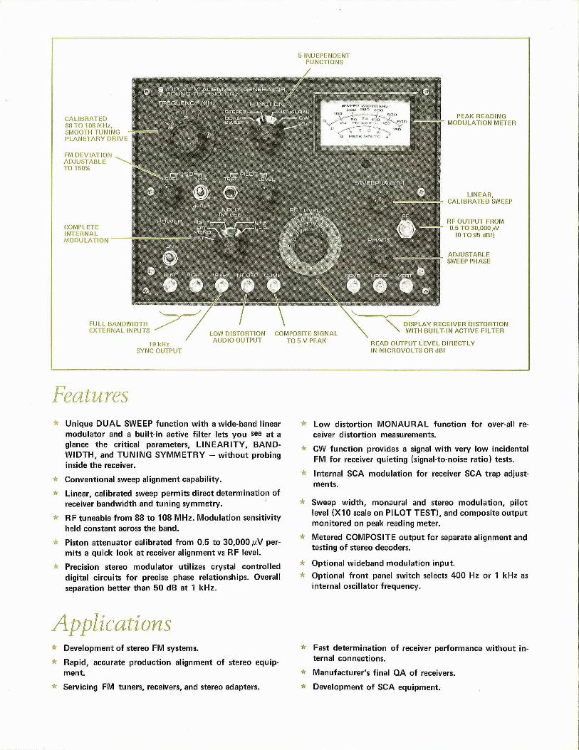
5 INDEPENDENT FUNCTIONS
CALIBRATED 88 TO 108 MHz, SMOOTH TUNING PLANETARY DRIVE
FM DEVIATION ADJUSTABLE TO 150%
COMPLETE INTERNAL MODULATION
PEAK READING MODULATION METER
LINEAR, CALIBRATED SWEEP
RF OUTPUT FROM 0,5 TO 30,000 nV
(0 TO 95 dBf)
ADJUSTABLE SWEEP PHASE
FULL BANDWIDTH EXTERMAI INPUTS
19 kHz SYNC OUTPUT
LOW DISTORTION AUDIO OUTPUT
COMPOSITE SIGNAL TO 5 V PEAK
DISPLAY RECEIVER DISTORTION WITH BUILT-IN ACTIVE FILTER
READ OUTPUT LEVEL DIRECTLY IN MICROVOLTS OR dBf
^'natures Unique DUAL SWEEP funct ion with a wide-band linear modulator and a built-in active f i l ter lets you see at a glance the critical parameters, L INEARITY, BANDWIDTH, and TUNING SYMMETRY - wi thout probing inside the receiver.
Conventional sweep alignment capability.
Linear, calibrated sweep permits direct determination of receiver bandwidth and tuning symmetry.
RF tuneable f rom 88 to 108 MHz. Modulation sensitivity held constant across the band.
Piston attenuator calibrated f rom 0.5 to 30,000 /uV permits a quick look at receiver alignment vs RF level.
Precision stereo modulator utilizes crystal controlled digital circuits for precise phase relationships. Overall separation better than 50 dB at 1 kHz.
A Low distort ion MONAURAL funct ion for over-all receiver distort ion measurements.
* CW funct ion provides a signal wi th very low incidental FM for receiver quieting (signal-to-noise ratio) tests.
* Internal SCA modulation for receiver SCA trap adjustments.
* Sweep wid th , monaural and stereo modulat ion, pi lot level (X10 scale on PILOT TEST), and composite output monitored on peak reading meter.
* Metered COMPOSITE output for separate alignment and testing of stereo decoders.
* Optional wideband modulation input. Optional f ront panel switch selects 400 Hz or 1 kHz as internal oscillator frequency.
Applications Development of stereo FM systems.
Rapid, accurate production alignment of stereo equipment.
Servicing FM tuners, receivers, and stereo adapters.
* Fast determination of receiver performance wi thout internal connections.
Manufacturer's final QA of receivers.
Development of SCA equipment.

What Dual Sweep Does Dual sweep permits receiver alignment with unexcelled rapidity and precision by providing an accurate scope display of linearity and distortion. A highly linear modulator driven by a dual frequency sweep signal yields far more resolution and accuracy than conventional sweep techniques. All the signals required for a display of receiver distortion, bandwidth, and tuning characteristics are provided by the 1000A. The text below describes how the dual frequency sweep method works.
I low Dual Sweep Works
To understand the operation of DUAL SWEEP, consider the effect of a nonlinear S-curve on a low level 10 kHz modulating signal. As shown in Figure 1, changing the carrier frequency from F1 to F2 shifts the demodulation region to a different portion of the S-curve and results in a change in the detected 10 kHz output voltage. The ideal S-curve would have a constant amplitude in the pass band.
Figure 1.
10 kHz output level is actually a measure of S-curve slope over a very small region. As the carrier frequency is shifted over the receiver band, changes in the detected output are directly proportional to S-curve non-linearity and resulting receiver distortion. Receiver linearity could actually be measured by hand tuning an oscillator with 10 kHz low level FM and plotting receiver output voltage vs. carrier frequency (Figure 2) — a slow and cumbersome technique.
Figure 2.
FREQUENCY
The DUAL SWEEP signal eliminates the need for hand tuning by superimposing the 10 kHz on a 60 Hz sweep signal, permitting a scope display. Receiver output will be a 60 Hz waveform with 10 kHz superimposed on it. In order to determine the 10 kHz amplitude (our measure of linearity and thus distortion), the 60 Hz must be filtered out. The 1000A has a built-in filter to provide a clean 10 kHz signal. By using the 60 Hz modulation signal for horizontal deflection of a scope and the filtered detector output for vertical deflection, receiver linearity will be displayed as in Figure 3.
Illl
'II l l i l l i i i
l l l l i 111 l l t l i i
Figure 3 .
FREQUENCY
Advantages of Dual Sweep Because DUAL SWEEP measures the slope of the S-curve, it provides a display of receiver distortion which is far more sensitive than that obtained by conventional sweep methods. D U A L SWEEP has all the advantages of minimum distortion alignment (it is a direct measure of IM distortion) and yet retains the benefits of conventional sweep alignment. We all know that sweep alignment is highly desireable, not only because of the rapidity and ease of adjustment that goes with a scope display, but because of the information contained in the pattern we see. A conventional sweep display provides immediate information on the effect of receiver adjustments on tuning symmetry and bandwidth, but is not a sensitive measure of distortion. Alignment with a distortion analyzer can yield low distortion but may result in critical tuning characteristics. DUAL SWEEP combines the advantages of both techniques — and eliminates the disadvantages of each.
Not only can a receiver's distortion be measured over its full bandwidth using DUAL SWEEP, but the character of the distortion is displayed on the scope. Figure 4 shows a scope display of the DUAL SWEEP pattern for a receiver with even-order distortion.
HORIZ - 50 kHz/cm
Figure 4. D U A L S W E E P pattern for 0.7% T H D .

FM RF OUTPUT
T U N I N G R A N G E : 8 8 t o 1 0 8 M H z . 6 : 1 p lane ta ry d r i v e p rov ides a p p r o x . 1 0 k H z t u n i n g r e s o l u t i o n .
R E S I D U A L F M (CW M O D E ) : < 2 5 H z , 2 0 Hz t o 1 5 k H z (measures q u i e t i n g t o - 7 0 d B ) .
D R I F T : < 1 0 k H z / h r a f ter 1 h o u r w a r m - u p .
T O T A L H A R M O N I C D I S T O R T I O N : < 0 . 1 % at 1 k H z m o n a u r a l , < 0 . 2 % s te reo , 1 0 0 % m o d u l a t i o n .
R E S I D U A L F M ( M O N O O R S T E R E O ) : < 7 5 H z , 2 0 H z t o 1 5 k H z .
R E S I D U A L 38 k H z S U B C A R R I E R : < 0 . 5 % , app l ies t o stereo o n l y .
O U T P U T L E V E L : 0 . 5 t o 3 0 , 0 0 0 M V i n t o 5 0 o h m l o a d , c o n t i n u o u s l y ad jus tab le . A c c u r a c y is ± 1 d B at 9 8 M H z . Sealed RF u n i t p rov ides s u f f i c i e n t l y l o w leakage t o p e r m i t accura te measurements b e l o w 0 . 5 j i V ,
O U T P U T I M P E D A N C E : 5 0 H , V S W R < 1 . 3 , 2 0 0 V d c i so la t i on .
DUAL SWEEP
I N C R E M E N T A L L I N E A R I T Y : + 0 . 3 % f o r 150 k H z b a n d w i d t h . ( I n c r e m e n t a l l i nea r i t y is t he change in smal l signal F M d e v i a t i o n sens i t i v i t y ove r a s ta ted b a n d w i d t h and is equ iva len t t o peak in ter m o d u l a t i o n d i s t o r t i o n ) .
S W E E P W I D T H : A d j u s t a b l e and me te red f r o m 0 t o 6 0 0 k H z .
S W E E P L I N E A R I T Y : ± 3 % o f w i d t h .
R C V R I N P U T : I m p e d a n c e : > 1 0 0 K U at 10 k H z , > 1 0 M f t at 6 0 H z . M a x i m u m i n p u t is 2 5 vo l t s peak .
V E R T O U T P U T : Impedance 1 0 K « . R C V R i n p u t - t o - V E R T o u t p u t gain as 3 0 at 10 k H z . 10 k H z m o d u l a t i o n in D U A L S W E E P ss 10%.
H O R I Z O U T P U T : Impedance 2 0 K J J . Level a s 2 0 vo l t s peak - to -peak .
S W E E P P H A S E : A d j u s t a b l e over 6 0 ° range at 6 0 H z .
S E P A R A T I O N : > 5 0 d B at 1 k H z . S p e c i f i c a t i o n inc ludes m o n o / s t e r e o subchanne l separa t ion and p i l o t phase accuracy and is app l i cab le t o c o m p o s i t e o r RF o u t p u t s .
P I L O T : 19 k H z ± 2 H z , ad jus tab le f r o m 0 t o 2 0 % . PI L O T T E S T pushb u t t o n removes ex te rna l L E F T and R I G H T or I N T O S C m o d u l a t i o n and expands m e t e r scale t o 1 5 % f u l l scale.
E X T E R N A L L E F T (MONO) AND RIGHT INPUTS
F R E Q U E N C Y R E S P O N S E : ± 0 . 5 d B , 5 0 Hz t o 15 k H z .
I N P U T I M P E D A N C E : 1 0 K J 2 .
L E V E L : as 0 . 4 V rms f o r 1 0 0 % m o d u l a t i o n (no damage at 15 v o l t s p e a k ) .
1 9 k l l * O U T P U T
W A V E F O R M : 19 k H z ± 2 Hz squarewave , a s 5 vo l t s peak - to -peak .
O U T P U T I M P E D A N C E : 3 .3KJ2 .
INT 0SC OUTPUT
F R E Q U E N C Y : 1 k H z ± 1 0 % , 10 k H z w i t h F U N C T I O N sw i t ch o n D U A L S W E E P , 67 k H z o n S C A .
T O T A L H A R M O N I C D I S T O R T I O N : < 0 . 1 % at 1 k H z .
L E V E L : a s 2 V rms .
O U T P U T I M P E D A N C E : I K t t .
COMPOSITE OUTPUT
L E V E L : A d j u s t a b l e and me te red f r o m 0 t o 5 vo l t s peak .
O U T P U T I M P E D A N C E : < 6 0 0 f i .
T O T A L H A R M O N I C D I S T O R T I O N : < 0 . 2 % at 5 vo l t s peak.
R E S I D U A L 38 k H z S U B C A R R I E R : > 5 0 dB d o w n f r o m 5 vo l t s peak . A p p l i c a b l e t o stereo o n l y .
R E S I D U A L H U M A N D N O I S E : > 6 0 d B d o w n f r o m 5 vo l t s peak.
M E T E R E D FUNCTIONS
M O N O A N D S T E R E O : 0 t o 1 5 0 % peak read ing .
D U A L S W E E P : 0 t o 6 0 0 k H z sweep w i d t h .
P I L O T : 0 t o 15%.
C O M P O S I T E O U T P U T : 0 t o 5 vo l t s peak .
A C C U R A C Y : ± 7 % o f read ing ± 2 % o f f u l l scale, 8 8 t o 1 08 M H z .
O P T I O N ; ;
W I D E B A N D A U X I L I A R Y I N P U T (Rear Panel B N C ) : T h i s w i d e b a n d m o d u l a t i o n i n p u t m a y be used f o r S C A p r o g r a m m a t e r i a l , in ter m o d u l a t i o n d i s t o r t i o n tests, or f o r add ing o t h e r c o m p l e x m o d u l a t i o n t o t h e c o n v e n t i o n a l s tereo signals. O rde r M 1 .
I N T E R N A L O S C I L L A T O R : W i t h y o u r o rde r y o u m a y spec i fy a 4 0 0 H z in te rna l osc i l l a to r instead o f .the s tandard 1 k H z at n o add i t i o n a l charge.
4 0 0 H z / 1 k H z I N T E R N A L O S C I L L A T O R : F r o n t panel togg le sw i t ch a l l ows cho ice o f 4 0 0 Hz o r 1 k H z in te rna l osc i l l a to r f r e q u e n c y . Perm i t s m e a s u r e m e n t o f receiver d i s t o r t i o n at 4 0 0 H z , separat ion at 1 k H z as spec i f ied in I H F s tandards. O rde r M 2 .
B R O A D C A S T Q U A L I T Y S T E R E O M O D U L A T O R : W h e n M 3 is i n c l u d e d , a m o r e c o m p l e x s tereo f i l t e r is ins ta l led in t he 1 0 0 0 A . T h i s p e r m i t s a separa t ion spec i f i ca t i on o f 5 0 d B f r o m 5 0 Hz t o 8 k H z decreasing t o 4 0 dB at 15 k H z . Essent ia l f o r receiver design and f o r receiver tes t ing and eva lua t i on at h igh a u d i o f r equenc ies . O r d e r M 3 .
G E N E R A L
D I M E N S I O N S : 8 - 3 / 8 " h igh x 1 1 - 1 / 8 " w i d e x 1 1 - 3 / 4 " deep.
P O W E R : 1 1 5 V ± 1 0 % , 5 0 t o 6 0 H z , 12.5 W.
W E I G H T : 12 l bs ;
S H I P P I N G W E I G H T : 18 lbs.
Al l pi-ices f.o.b. Campbell, California — data subject to change wi thout notice
P r i n t e d in U .S .A . 8 / 7 7 m m
RflHIHIHMHnBHBH