nvent eriflex flexibar · what is nvent eriflex flexibar? flexibar can be used for making power...
TRANSCRIPT
nVent ERIFLEX FlexibarTechnical handbook

In accordance with its policy of continuous improvement, the Company reserves the right to change specifications and designs without notice. All illustrations, descriptions, dimensions and weights in this catalogue are for guidance and cannot be held binding on the Company.
2 | nVent.com/ERIFLEX

TABLE OF CONTENT
What is nVent ERIFLEX Flexibar? 4
Flexibar benefits 5
Applications 7
Main Technical Specifications 8
Flexibar Selection 9
• Selection of Flexibar according to the internal temperature of the panel 9
• How Sizing conductors. 9
• Temperature rise of the conductor. 9
• Flexibar in parallel 9
IEC Ampacities 10
UL Ampacities 11
nVent ERIFLEX Flexibar Advanced UL & CSA Certification 12
Skin Effect on Alternative Current Application 13
Current Density 14
Skin Effect and Frequency 15
Power Dissipation 16
Thermal Short-Circuit Strength 17
Flexibility: Innovative Patent Insulation 18
Flexibility and Bending Radius Comparison with Cable 19
Class II Insulation 20
Wrinkle on Insulation 22
Altitude Effect 22
Halogen-Free (HF) 22
Low Smoke (LS) 23
Flame Retardant (FR) 23
EN 45545-2 Fire Testing to Railway Components 24
Certifications for Marine & Offshore 25
How to Achieve a Good Electrical Connection 26
• Contact surface conditions 26
• Contact surface (S) - Overlap 26
• Necessary Clamping Force (F) 26
• Clamping torque calculation 27
• Two Ways to Connect FLEXIBAR in Parallel: 28
• Flexibar Connected to an Electrical device: 28
Recommended Fabrication Procedures 29
• General Design Guide - Fabricated Parts 29
• Safety 29
• Cutting 30
• Bending 30
• Twisting 31
• Folding 31
• Stripping 32
• Cut Finishes 32
• Drilling / Punching 33
• Fabrication Steps order 34
• Connecting 34
• Flexibar Connection on MCCB 35
• Accessories and solutions for connection 36
• Flexibar Direct connection on power & distribution blocks 39
• Fixing/Securing 42
• Accessories and solution for Fixing/Securing 45
Recommended Fabrication Procedures 46
Fixing and Securing nVent ERIFLEX Flexibar Advanced 47
Recommended Fabrication Tools 48
Made to Order Solutions (MTO) 56
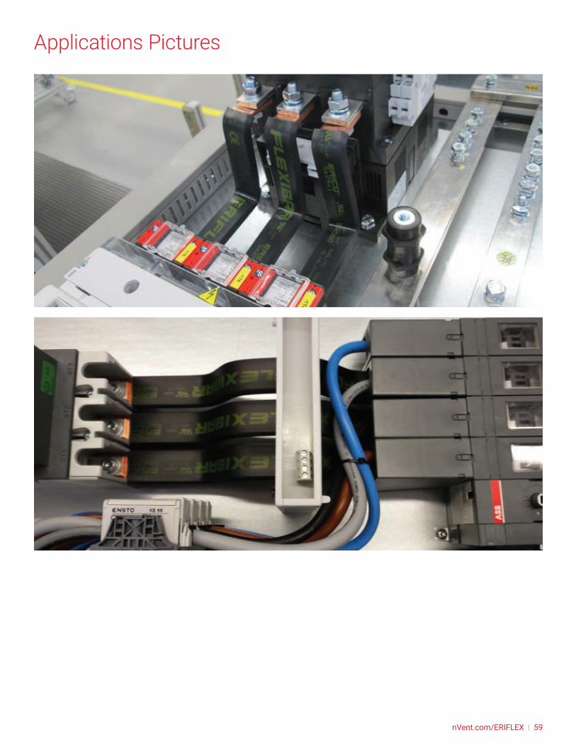
Applications Pictures 57
nVent Eriflex Software 60
Other nVent ERIFLEX Litterature 61
Contact us! 64
nVent.com/ERIFLEX | 3

What is nVent ERIFLEX Flexibar?Flexibar can be used for making power connections on devices or for creating links that can be adapted to any requirement. Guaranteeing safety and high quality finish, they provide an undeniably attractive touch.
Based on the most commonly used sizes and the electrical capacities of the usual nominal values, the Flexibar range of flexible bars is suitable for most connection or linking requirements.
Flexibar consists of pure electrolytic copper (tinned or plain) layers within a protective self-extinguishing sleeve.
• Flexibar Advanced: TPE Compound (haloge-free, Flame retardant, Low Smoke and 115°C)
• Flexibar Standard: PVC Compound (Flame retardant and 105°C)
• Flexibar Summum: Silicon Compound (halogen-free, flame retardant and 280°C)
The individual layers slide smoothly against one another allowing the Flexibar to be easily shaped to fit a wide range of panel layouts.
The insulating sleeve is grooved on the inner surface, reducing the contact surface with the laminates to less than 20%, increasing flexibility and making installation easier. It also helps releasing constraint on insulation, improving safety and reliability.
Easily formed even in its largest size, Flexibar vastly improves design and assembly flexibility and the aesthetic of finished panels. All Flexibar cross sections can be bended, folded, or twisted with a very small bending radius for shorter and more compact power connections between main power and distribution equipment, between transformers and
busduct, between busduct and electrical cabinets, and many other types of connections.
When compared to standard round cable, Flexibar offers space saving advantages due to a tighter bend radius and the ability to replace multiple round conductors with a single piece of Flexibar.
Modification of fewer conductors and the elimination of ring terminals can result in significant cost and labor reduction.
Flexibar is a flexible busbar wire replacement solution for low voltage applications available from 19.5 mm² up to 1200 mm² and 125 A to 2800 A with a single conductor per phase or up to 4500A with 3 conductors per phase.
4 | nVent.com/ERIFLEX
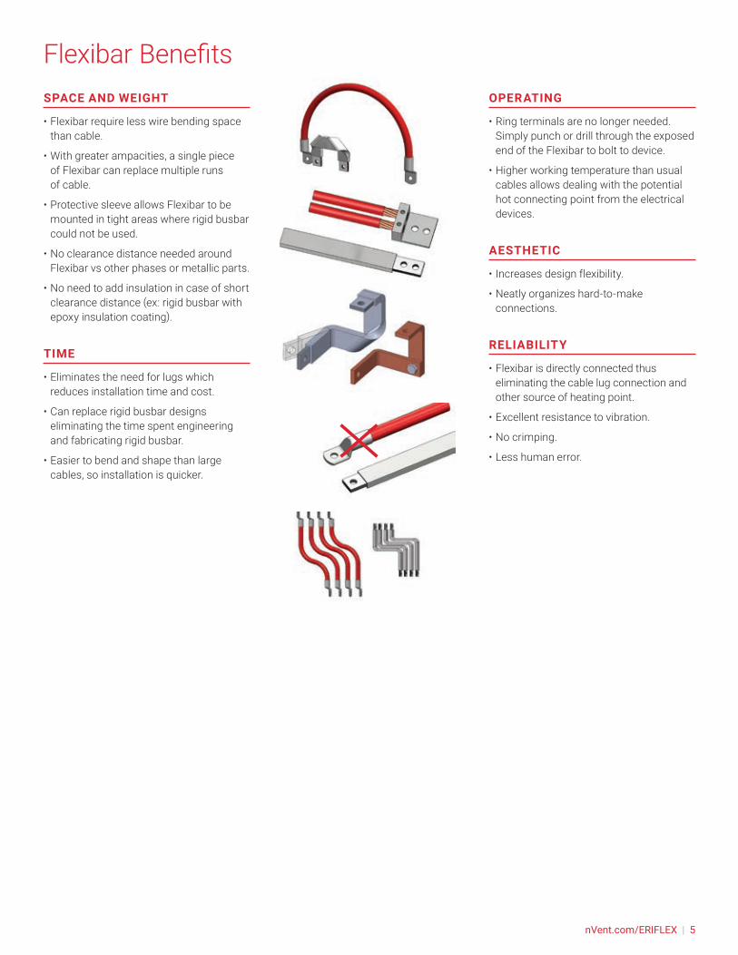
Flexibar BenefitsSPACE AND WEIGHT
• Flexibar require less wire bending space than cable.
• With greater ampacities, a single piece of Flexibar can replace multiple runs of cable.
• Protective sleeve allows Flexibar to be mounted in tight areas where rigid busbar could not be used.
• No clearance distance needed around Flexibar vs other phases or metallic parts.
• No need to add insulation in case of short clearance distance (ex: rigid busbar with epoxy insulation coating).
TIME
• Eliminates the need for lugs which reduces installation time and cost.
• Can replace rigid busbar designs eliminating the time spent engineering and fabricating rigid busbar.
• Easier to bend and shape than large cables, so installation is quicker.
OPERATING
• Ring terminals are no longer needed. Simply punch or drill through the exposed end of the Flexibar to bolt to device.
• Higher working temperature than usual cables allows dealing with the potential hot connecting point from the electrical devices.
AESTHETIC
• Increases design flexibility.
• Neatly organizes hard-to-make connections.
RELIABILITY
• Flexibar is directly connected thus eliminating the cable lug connection and other source of heating point.
• Excellent resistance to vibration.
• No crimping.
• Less human error.
nVent.com/ERIFLEX | 5
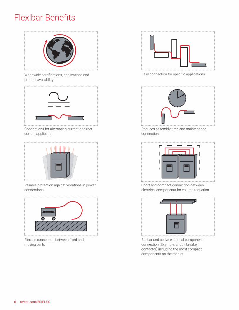
Flexibar Benefits
Worldwide certifications, applications and product availability
Connections for alternating current or direct current application
Reliable protection against vibrations in power connections
Flexible connection between fixed and moving parts
Easy connection for specific applications
Reduces assembly time and maintenance connection
Short and compact connection between electrical components for volume reduction
Busbar and active electrical component connection (Example: circuit breaker, contactor) including the most compact components on the market
6 | nVent.com/ERIFLEX

ENERGY INDUSTRY & BUILDINGS PANELBOARD
MACHINERYTRANSPORTATION
• Low Voltage Power Distribution and Control Applications
• Busbar Systems
• Motor Control Centers
• Drive Systems
• Switchboards
• Transformers
• Panelboards
• Control Panels
• Power Supplies
• Electrical Machinery
• UPS Systems
• Electrical Vehicle
Applications
nVent.com/ERIFLEX | 7

Flexibar Advanced Flexibar Standard Flexibar Summum
Finish: Tinned Tinned or Plain Plain
Material: Electrolytic copper Cu-ETP 99,9% purityThermoplastic Elastomer
Electrolytic copper Cu-ETP 99,9% purityPolyvinylchloride
Electrolytic copper Cu-ETP 99,9% puritySilicone
Maximum resistivity at 20°C 0.017241 ohms.mm2 / m
Dielectric strength: 20 kV/mm
Flammability rating: UL 94-V0 and IEC 60695-2-11 (Glow Wire Test 960 °C)
Halogen-free rating: UL® 2885IEC® 60754-1IEC® 62821-2
- IEC® 60754-1
IEC® 62821-2
Low smoke rating: IEC® 61034-2UL 2885ISO 5659-2
- -
UV Rating: UL 2556 and UL 854 - -
Typical Insulation Elongation: > 500% > 370% > 400%
Typical Insulation Thickness: 1.8 mm (0,070 inches) 2 mm (0,078 inches) 2 mm (0,078 inches)
Nominal Voltage: UL/CSA/IEC: 1,000 VAC; 1,500 VDC UL/CSA/IEC: 1,000 VAC; 1,500 VDC IEC: 1,000 VAC; 1,500 VDC
Working Temperature: -50 to 115°C (-58 to 239°F) -50 to 105°C (-58 to 221°F) -50 to 280°C (-58 to 536°F)
Certification Details: UL® 67UL® 758CSA 90005
UL® 67UL® 758CSA 90005
-
Complies With: IEC® 60695-2-11 (Glow Wire Test 960°C)IEC® 61439.1IEC® 61439.1 Class IICERoHSEN 45545: HL2 classification
Bureau Veritas (Marine & Offshore)
EAC
ABS American Bureau of Shipping
IEC® 60695-2-11 (Glow Wire Test 960°C) IEC® 61439.1IEC® 61439.1 Class IIABS American Bureau of ShippingBureau Veritas (Marine & Offshore)CEEACRoHS
IEC® 61439.1ABS American Bureau of ShippingCEEACRoHSEN 45545: HL3 classification for chapters R22 & R23
Main Technical Specifications
See our web site, nVent.com/ERIFLEX for last data update and certification documents
8 | nVent.com/ERIFLEX

SELECTION OF FLEXIBAR ACCORDING TO THE INTERNAL TEMPERATURE OF THE PANEL
When sizing a conductor, the air temperature around the conductor is a very important parameter. It’s affected by convection type, protection level of enclosure, the temperature rise, etc. Based on IEC 61439 standards, the ambient air temperature do not exceed +40°C and its average over a period of 24h does not exceed +35°C.
For Flexibar, we provided an ampacity table under different temperature rise, a lower temperature rise maybe used when the ambient temperature is higher than usual
For Flexibar, we recommend the maximum temperature rise does not exceed 50°C for a normal application.
Generally, 50°C is chosen as the default temperature rise considering the ambient temperature inside the panel is below 40°C. But when the connected part is an electrical component which may dissipate heat (for example circuit breaker) or the ventilation inside the enclosure is not efficient, it may necessary to choose lower temperature rise.
HOW SIZING CONDUCTORS.
The chart below demonstrate the general steps to determine Flexibar size
TEMPERATURE RISE OF THE CONDUCTOR.
Temperature rise of the conductor (ΔT) = Temperature of the conductor – Internal temperature of the panel.
Temperature rise of conductor = T2 - T1 = ΔT (C°)
Ex: For a requested current of 630A, with: T1 = 40ºC - T2 = 90ºC
ΔT = 90 - 40 = 50°C
In the ΔT 50ºC column, find the closest current value to 630A. Flexibar 5x32x1 -160 mm² - 640A (IEC).
Select Flexibar according to the terminal width of the equipment being connected.
FLEXIBAR IN PARALLEL
When using 2 or 3 Flexibar on edge in parallel for the same phase, use the current coefficient showed on the next IEC & UL ampacities tables:
Ex: 5 x 32 x 1 - ΔT = 50°C: 640 A (IEC)
*2 bars in parallel > 640 A x 1,72 = 1100 A
*3 bars in parallel > 640 A x 2,25 = 1440 A
*4 bars in parallel > 640 A x 2.93 = 1875 A
See next page for current coefficient by nVent ERIFLEX Flexibar Cross section
Flexibar Selection
Internal temperature of panel (T1)
Temperature of conductors (T2)
Ambient tem
perature
TEMPERATURE RISE (ΔT)
SERVICE CONDITIONS
DETERMINE CONDUCTOR SIZE
• Temperature rise (ΔT)
• Application
• Ambient temperature
• Max temp of the insulation
• Altitude
• Frequency
• Corrosion / Environment
• IEC or UL application
• Rated current
• Prefered dimension
• N° of bar per phase
• Safety margin
• Connected device characteristics
nVent.com/ERIFLEX | 9
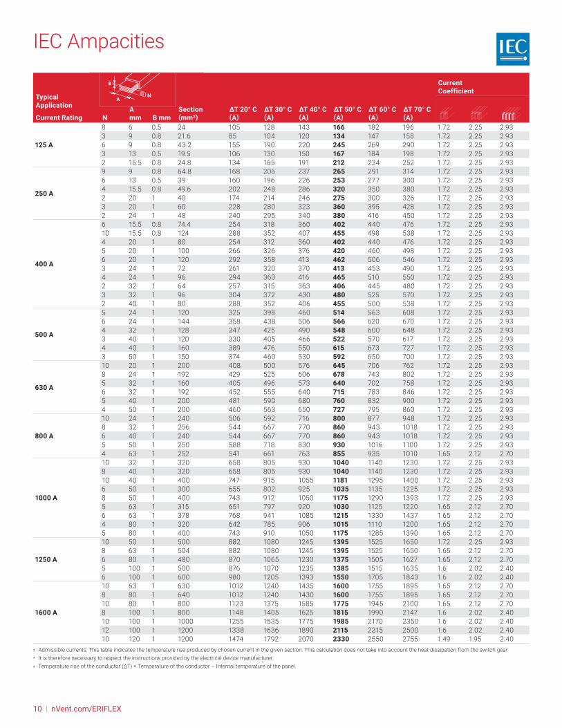
IEC Ampacities
Typical Application
Current RatingSection (mm²)
ΔT 20° C (A)
ΔT 30° C (A)
ΔT 40° C (A)
ΔT 50° C (A)
ΔT 60° C (A)
ΔT 70° C (A)
Current Coefficient
NA mm B mm
125 A
8 6 0.5 24 105 128 143 166 182 196 1.72 2.25 2.933 9 0.8 21.6 85 104 120 134 147 158 1.72 2.25 2.936 9 0.8 43.2 155 190 220 245 269 290 1.72 2.25 2.933 13 0.5 19.5 106 130 150 167 184 198 1.72 2.25 2.932 15.5 0.8 24.8 134 165 191 212 234 252 1.72 2.25 2.93
250 A
9 9 0.8 64.8 168 206 237 265 291 314 1.72 2.25 2.936 13 0.5 39 160 196 226 253 277 300 1.72 2.25 2.934 15.5 0.8 49.6 202 248 286 320 350 380 1.72 2.25 2.932 20 1 40 174 214 246 275 300 326 1.72 2.25 2.933 20 1 60 228 280 323 360 395 428 1.72 2.25 2.932 24 1 48 240 295 340 380 416 450 1.72 2.25 2.93
400 A
6 15.5 0.8 74.4 254 318 360 402 440 476 1.72 2.25 2.9310 15.5 0.8 124 288 352 407 455 498 538 1.72 2.25 2.934 20 1 80 254 312 360 402 440 476 1.72 2.25 2.935 20 1 100 266 326 376 420 460 498 1.72 2.25 2.936 20 1 120 292 358 413 462 506 546 1.72 2.25 2.933 24 1 72 261 320 370 413 453 490 1.72 2.25 2.934 24 1 96 294 360 416 465 510 550 1.72 2.25 2.932 32 1 64 257 315 363 406 445 480 1.72 2.25 2.933 32 1 96 304 372 430 480 525 570 1.72 2.25 2.932 40 1 80 288 352 406 455 500 538 1.72 2.25 2.93
500 A
5 24 1 120 325 398 460 514 563 608 1.72 2.25 2.936 24 1 144 358 438 506 566 620 670 1.72 2.25 2.934 32 1 128 347 425 490 548 600 648 1.72 2.25 2.933 40 1 120 330 405 466 522 570 617 1.72 2.25 2.934 40 1 160 389 476 550 615 673 727 1.72 2.25 2.933 50 1 150 374 460 530 592 650 700 1.72 2.25 2.93
630 A
10 20 1 200 408 500 576 645 706 762 1.72 2.25 2.938 24 1 192 429 525 606 678 743 802 1.72 2.25 2.935 32 1 160 405 496 573 640 702 758 1.72 2.25 2.936 32 1 192 452 555 640 715 783 846 1.72 2.25 2.935 40 1 200 481 590 680 760 832 900 1.72 2.25 2.934 50 1 200 460 563 650 727 795 860 1.72 2.25 2.93
800 A
10 24 1 240 506 592 716 800 877 948 1.72 2.25 2.938 32 1 256 544 667 770 860 943 1018 1.72 2.25 2.936 40 1 240 544 667 770 860 943 1018 1.72 2.25 2.935 50 1 250 588 718 830 930 1016 1100 1.72 2.25 2.934 63 1 252 541 661 763 855 935 1010 1.65 2.12 2.70
1000 A
10 32 1 320 658 805 930 1040 1140 1230 1.72 2.25 2.938 40 1 320 658 805 930 1040 1140 1230 1.72 2.25 2.9310 40 1 400 747 915 1055 1181 1295 1400 1.72 2.25 2.936 50 1 300 655 802 925 1035 1135 1225 1.72 2.25 2.938 50 1 400 743 912 1050 1175 1290 1393 1.72 2.25 2.935 63 1 315 651 797 920 1030 1125 1220 1.65 2.12 2.706 63 1 378 768 941 1085 1215 1330 1437 1.65 2.12 2.704 80 1 320 642 785 906 1015 1110 1200 1.65 2.12 2.705 80 1 400 743 910 1050 1175 1285 1390 1.65 2.12 2.70
1250 A
10 50 1 500 882 1080 1245 1395 1525 1650 1.72 2.25 2.938 63 1 504 882 1080 1245 1395 1525 1650 1.65 2.12 2.706 80 1 480 870 1065 1230 1375 1505 1627 1.65 2.12 2.705 100 1 500 876 1070 1235 1385 1515 1635 1.6 2.02 2.406 100 1 600 980 1205 1393 1550 1705 1843 1.6 2.02 2.40
1600 A
10 63 1 630 1012 1240 1435 1600 1755 1895 1.65 2.12 2.708 80 1 640 1012 1240 1430 1600 1755 1895 1.65 2.12 2.7010 80 1 800 1123 1375 1585 1775 1945 2100 1.65 2.12 2.708 100 1 800 1148 1405 1625 1815 1990 2147 1.6 2.02 2.4010 100 1 1000 1255 1535 1775 1985 2170 2350 1.6 2.02 2.4012 100 1 1200 1338 1636 1890 2115 2315 2500 1.6 2.02 2.4010 120 1 1200 1474 1792 2070 2330 2550 2755 1.49 1.95 2.40
• Admissible currents: This table indicates the temperature rise produced by chosen current in the given section. This calculation does not take into account the heat dissipation from the switch gear.• It is therefore necessary to respect the instructions provided by the electrical device manufacturer.• Temperature rise of the conductor (ΔT) = Temperature of the conductor – Internal temperature of the panel.
10 | nVent.com/ERIFLEX

UL Ampacities
Typical Application
Current RatingSection (mm²)
ΔT 20° C (A)
ΔT 30° C (A)
ΔT 35° C (A)
ΔT 40° C (A)
ΔT 45° C (A)
ΔT 50° C (A)
ΔT 60° C (A)
ΔT 65° C (A)
ΔT 70° C (A)
Current Coefficient
NEC® 310-1660° C
NEC® 310-1675° C
NEC® 310-1690° CN
A mm
B mm
125 A
3 9 0.8 21.6 101 126 138 148 158 167 185 193 201 1.72 2.25 2.933 13 0.5 19.5 102 128 139 150 160 169 187 195 203 1.72 2.25 2.932 15.5 0.8 24.8 121 152 166 178 190 201 222 232 241 1.72 2.25 2.936 13 0.5 39 150 188 205 221 235 249 275 287 299 1.72 2.25 2.936 9 0.8 43.2 153 192 210 226 241 255 281 293 305 1.72 2.25 2.93
250 A
2 20 1 40 168 211 229 247 263 279 307 321 334 1.72 2.25 2.934 15.5 0.8 49.6 178 223 243 262 279 295 326 340 354 1.72 2.25 2.932 24 1 48 195 244 266 286 305 323 357 373 388 1.72 2.25 2.933 20 1 60 210 263 286 308 328 347 383 400 416 1.72 2.25 2.936 15.5 0.8 74.4 225 282 308 331 353 374 412 430 448 1.72 2.25 2.933 24 1 72 243 304 331 356 379 402 443 463 482 1.72 2.25 2.934 20 1 80 246 308 336 361 385 408 450 470 489 1.72 2.25 2.932 32 1 64 248 311 338 364 388 411 454 474 493 1.72 2.25 2.93
400 A
5 20 1 100 280 351 382 411 438 464 512 535 556 1.72 2.25 2.934 24 1 96 285 356 388 418 445 472 520 543 565 1.72 2.25 2.932 40 1 80 301 376 409 440 470 497 549 573 596 1.72 2.25 2.933 32 1 96 308 385 419 451 481 510 562 587 611 1.72 2.25 2.936 20 1 120 311 390 424 457 487 516 569 594 618 1.72 2.25 2.935 24 1 120 322 403 439 472 504 534 589 615 640 1.72 2.25 2.936 24 1 144 357 448 487 524 559 592 653 682 710 1.72 2.25 2.934 32 1 128 359 449 489 526 561 594 655 684 712 1.72 2.25 2.933 40 1 120 371 464 505 544 580 614 677 707 736 1.72 2.25 2.935 32 1 160 405 507 552 594 633 671 740 773 804 1.72 2.25 2.938 24 1 192 424 531 578 622 663 702 775 809 841 1.72 2.25 2.934 40 1 160 432 541 589 633 675 715 789 824 857 1.72 2.25 2.936 32 1 192 448 561 611 657 701 742 819 855 889 1.72 2.25 2.933 50 1 150 449 562 612 658 702 743 820 856 891 1.72 2.25 2.9310 24 1 240 484 606 660 710 757 802 885 924 961 1.72 2.25 2.935 40 1 200 486 608 662 712 759 804 887 926 964 1.72 2.25 2.93
800 A
4 50 1 200 521 651 709 763 813 861 950 992 1032 1.72 2.25 2.938 32 1 256 525 657 715 770 821 869 959 1001 1042 1.72 2.25 2.936 40 1 240 535 669 728 784 835 885 976 1019 1061 1.72 2.25 2.933 63 1 189 549 687 747 804 857 907 1002 1046 1088 1.65 2.12 2.705 50 1 250 583 730 794 855 911 965 1065 1112 1157 1.72 2.25 2.936 45 1 270 588 736 801 862 919 973 1074 1121 1167 1.72 2.25 2.9310 32 1 320 595 745 811 873 931 986 1088 1136 1182 1.72 2.25 2.938 40 1 320 628 786 855 920 981 1039 1146 1197 1246 1.72 2.25 2.934 63 1 252 633 792 861 927 988 1046 1155 1205 1255 1.65 2.12 2.706 50 1 300 641 802 873 940 1002 1061 1171 1222 1272 1.72 2.25 2.933 80 1 240 675 844 918 988 1053 1115 1231 1285 1337 1.65 2.12 2.7010 40 1 400 702 879 956 1029 1097 1162 1282 1338 1393 1.72 2.25 2.935 63 1 315 706 883 961 1033 1102 1167 1288 1344 1399 1.65 2.12 2.708 50 1 400 741 927 1009 1085 1157 1226 1352 1412 1469 1.72 2.25 2.93
1200 A
6 63 1 378 772 966 1051 1130 1205 1276 1408 1470 1530 1.65 2.12 2.704 80 1 320 776 970 1056 1136 1211 1282 1415 1477 1538 1.65 2.12 2.7010 50 1 500 831 1040 1132 1217 1298 1375 1517 1584 1648 1.72 2.25 2.935 80 1 400 861 1077 1172 1260 1344 1423 1570 1640 1706 1.65 2.12 2.708 63 1 504 886 1108 1205 1297 1383 1464 1616 1687 1756 1.65 2.12 2.706 80 1 480 938 1172 1275 1372 1463 1549 1709 1785 1858 1.65 2.12 2.7010 63 1 630 985 1232 1341 1442 1538 1628 1797 1876 1953 1.65 2.12 2.70
1600 A
5 100 1 500 1041 1301 1416 1523 1624 1719 1898 1982 2062 1.6 2.02 2.408 80 1 640 1073 1341 1460 1570 1674 1773 1956 2043 2126 1.65 2.12 2.706 100 1 600 1132 1414 1539 1655 1765 1869 2062 2153 2241 1.6 2.02 2.4010 80 1 800 1187 1484 1614 1736 1851 1960 2164 2259 2351 1.65 2.12 2.708 100 1 800 1279 1598 1739 1870 1994 2111 2330 2433 2532 1.6 2.02 2.40
2000 A 10 100 1 1000 1413 1765 1921 2066 2203 2332 2574 2688 2797 1.6 2.02 2.4012 100 1 1200 1537 1920 2089 2247 2396 2537 2800 2924 3043 1.6 2.02 2.40
• Admissible currents: This table indicates the temperature rise produced by chosen current in the given section. This calculation does not take into account the heat dissipation from the switch gear.• It is therefore necessary to respect the instructions provided by the electrical device manufacturer.• Temperature rise of the conductor (ΔT) = Temperature of the conductor – Internal temperature of the panel.
nVent.com/ERIFLEX | 11
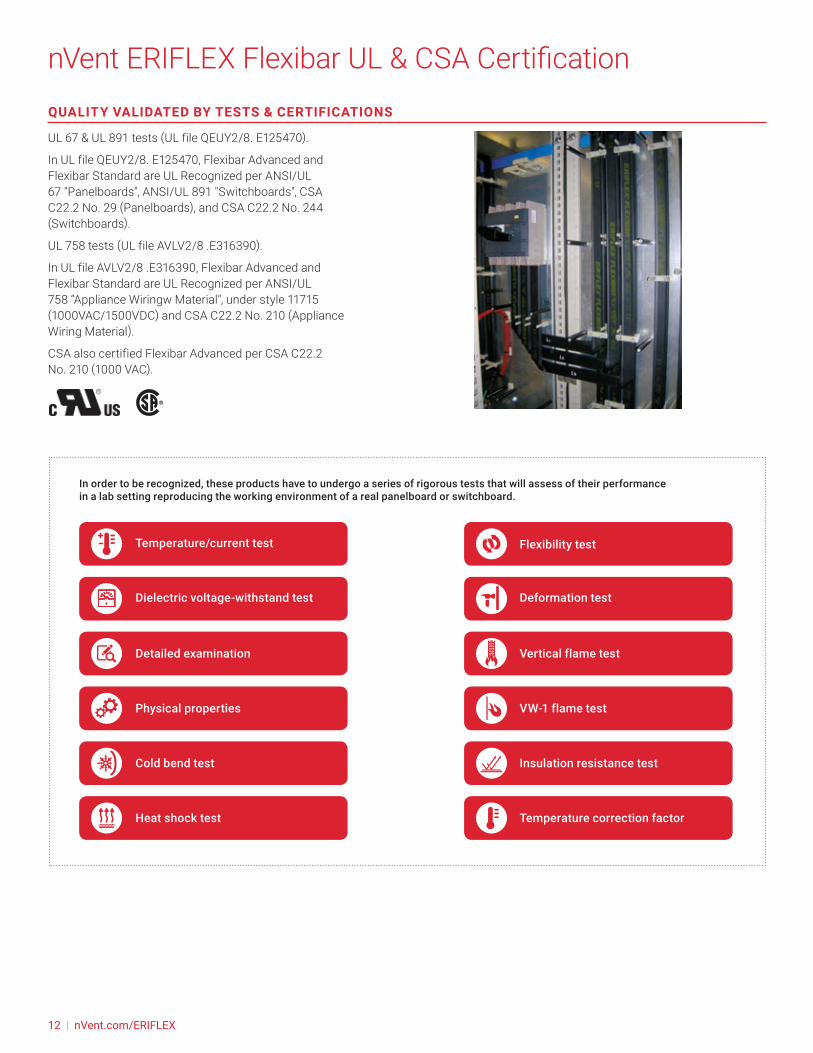
nVent ERIFLEX Flexibar UL & CSA CertificationQUALITY VALIDATED BY TESTS & CERTIFICATIONS
UL 67 & UL 891 tests (UL file QEUY2/8. E125470).
In UL file QEUY2/8. E125470, Flexibar Advanced and Flexibar Standard are UL Recognized per ANSI/UL 67 "Panelboards", ANSI/UL 891 "Switchboards", CSA C22.2 No. 29 (Panelboards), and CSA C22.2 No. 244 (Switchboards).
UL 758 tests (UL file AVLV2/8 .E316390).
In UL file AVLV2/8 .E316390, Flexibar Advanced and Flexibar Standard are UL Recognized per ANSI/UL 758 “Appliance Wiringw Material", under style 11715 (1000VAC/1500VDC) and CSA C22.2 No. 210 (Appliance Wiring Material).
CSA also certified Flexibar Advanced per CSA C22.2 No. 210 (1000 VAC).
In order to be recognized, these products have to undergo a series of rigorous tests that will assess of their performance in a lab setting reproducing the working environment of a real panelboard or switchboard.
Temperature/current test Flexibility test
Dielectric voltage-withstand test Deformation test
Detailed examination Vertical flame test
Physical properties VW-1 flame test
Cold bend test Insulation resistance test
Heat shock test Temperature correction factor
12 | nVent.com/ERIFLEX
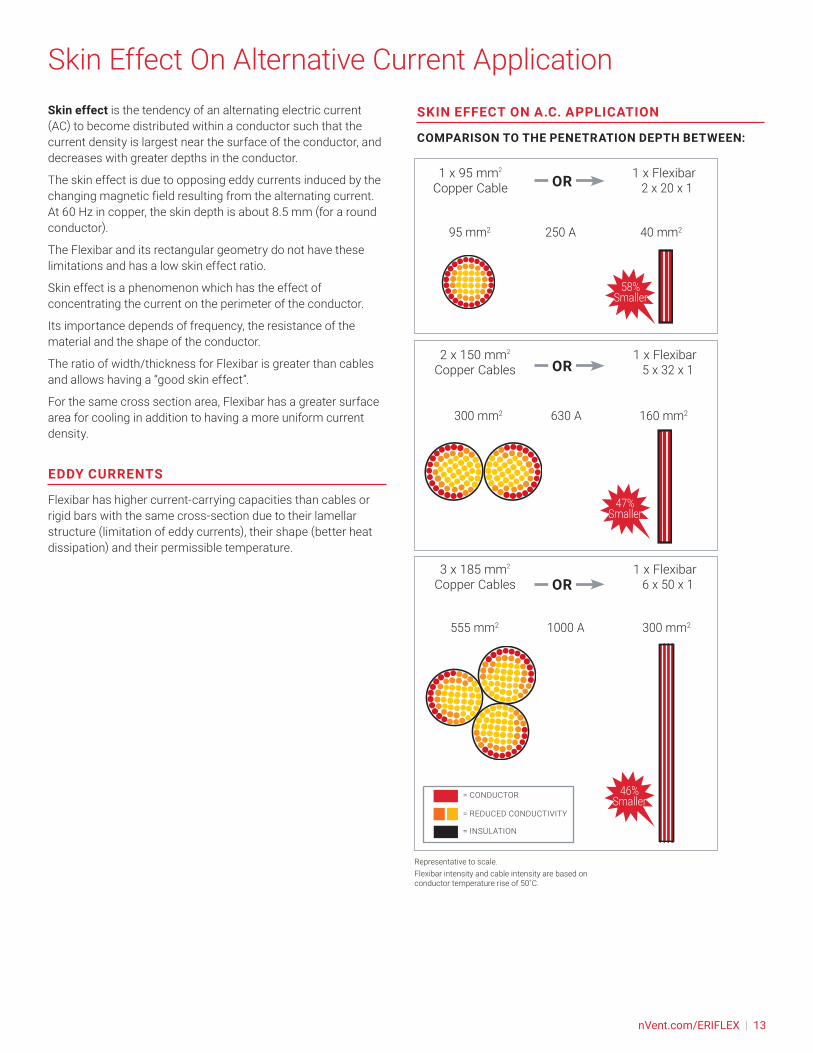
Skin Effect On Alternative Current ApplicationSkin effect is the tendency of an alternating electric current (AC) to become distributed within a conductor such that the current density is largest near the surface of the conductor, and decreases with greater depths in the conductor.
The skin effect is due to opposing eddy currents induced by the changing magnetic field resulting from the alternating current. At 60 Hz in copper, the skin depth is about 8.5 mm (for a round conductor).
The Flexibar and its rectangular geometry do not have these limitations and has a low skin effect ratio.
Skin effect is a phenomenon which has the effect of concentrating the current on the perimeter of the conductor.
Its importance depends of frequency, the resistance of the material and the shape of the conductor.
The ratio of width/thickness for Flexibar is greater than cables and allows having a “good skin effect”.
For the same cross section area, Flexibar has a greater surface area for cooling in addition to having a more uniform current density.
EDDY CURRENTS
Flexibar has higher current-carrying capacities than cables or rigid bars with the same cross-section due to their lamellar structure (limitation of eddy currents), their shape (better heat dissipation) and their permissible temperature.
1 x 95 mm2 1 x Flexibar Copper Cable 2 x 20 x 1
SKIN EFFECT ON A.C. APPLICATION
COMPARISON TO THE PENETRATION DEPTH BETWEEN:
OR
OR
OR
95 mm2 250 A 40 mm2
300 mm2 630 A 160 mm2
555 mm2 1000 A 300 mm2
58% Smaller
47% Smaller
46% Smaller
2 x 150 mm2 1 x Flexibar
Copper Cables 5 x 32 x 1
3 x 185 mm2 1 x Flexibar
Copper Cables 6 x 50 x 1
= CONDUCTOR
= REDUCED CONDUCTIVITY
= INSULATION
Representative to scale.Flexibar intensity and cable intensity are based on conductor temperature rise of 50˚C.
nVent.com/ERIFLEX | 13
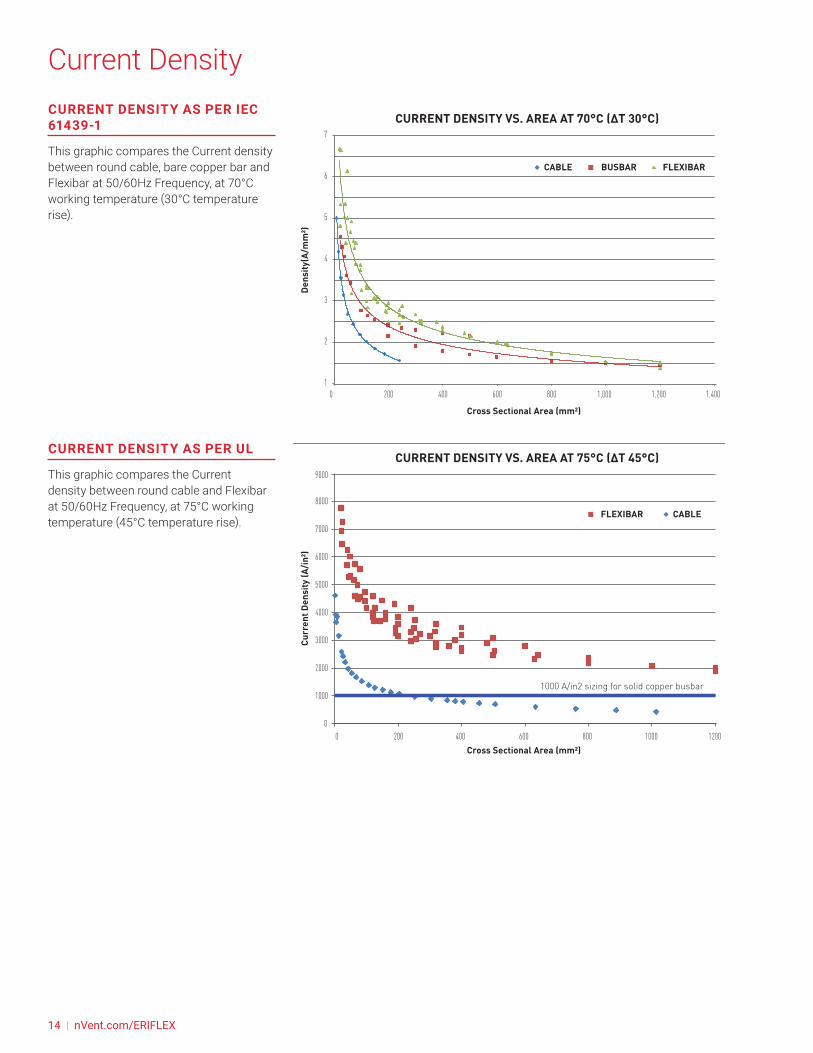
Current DensityCURRENT DENSITY AS PER IEC 61439-1
This graphic compares the Current density between round cable, bare copper bar and Flexibar at 50/60Hz Frequency, at 70°C working temperature (30°C temperature rise).
CURRENT DENSITY AS PER UL
This graphic compares the Current density between round cable and Flexibar at 50/60Hz Frequency, at 75°C working temperature (45°C temperature rise).
Cross Sectional Area (mm2)
Dens
ity(A
/mm
²)
BUSBAR FLEXIBARCABLE
CURRENT DENSITY VS. AREA AT 70°C (ΔT 30°C)
1
2
3
4
5
6
7
0 200 400 600 800 1,000 1,200 1,400
Cross Sectional Area (mm2)
Curr
ent D
ensi
ty (A
/in2)
FLEXIBAR CABLE
CURRENT DENSITY VS. AREA AT 75°C (ΔT 45°C)
0
1000
2000
3000
4000
5000
6000
7000
8000
9000
0 200 400 600 800 1000 1200
1000 A/in2 sizing for solid copper busbar
14 | nVent.com/ERIFLEX
Skin Effect And FrequencySKIN EFFECT IS INCREASING IN FUNCTION OF THE FREQUENCY.
The current ratings of Flexibar as published in our catalog and web site are based on operating frequency up to 100HZ. As the fact that all copper conductors have higher impedance at higher frequencies, so a de-rating factor should be applied for a particular application operated at higher frequencies. However, the rectangular cross-section of Flexibar reduces this effect as compared to cables with round cross-section.
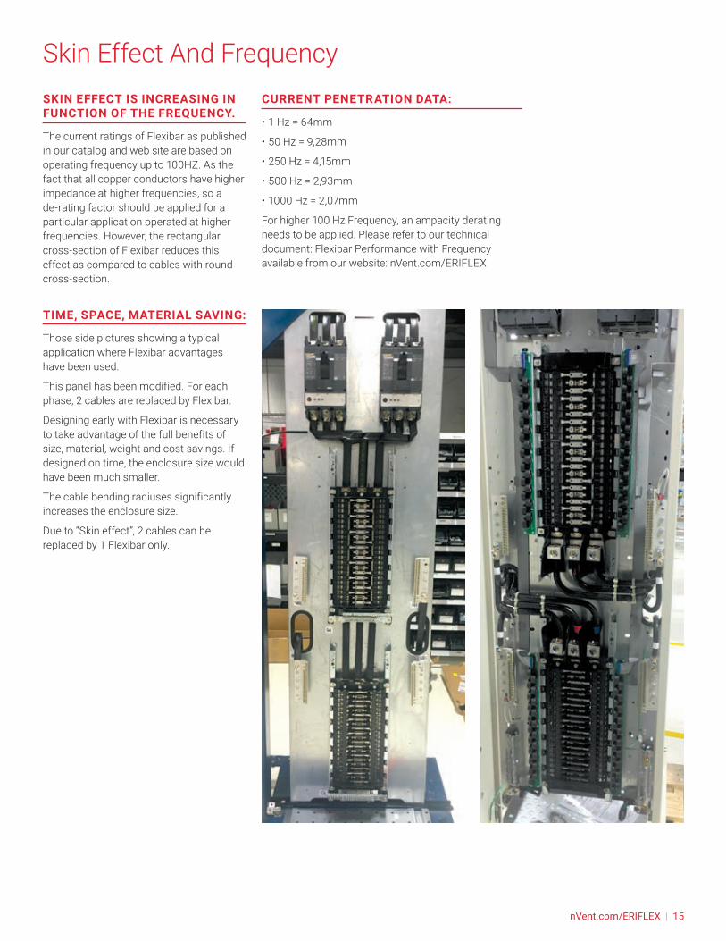
TIME, SPACE, MATERIAL SAVING:
Those side pictures showing a typical application where Flexibar advantages have been used.
This panel has been modified. For each phase, 2 cables are replaced by Flexibar.
Designing early with Flexibar is necessary to take advantage of the full benefits of size, material, weight and cost savings. If designed on time, the enclosure size would have been much smaller.
The cable bending radiuses significantly increases the enclosure size.
Due to “Skin effect”, 2 cables can be replaced by 1 Flexibar only.
CURRENT PENETRATION DATA:
• 1 Hz = 64mm
• 50 Hz = 9,28mm
• 250 Hz = 4,15mm
• 500 Hz = 2,93mm
• 1000 Hz = 2,07mm
For higher 100 Hz Frequency, an ampacity derating needs to be applied. Please refer to our technical document: Flexibar Performance with Frequency available from our website: nVent.com/ERIFLEX
nVent.com/ERIFLEX | 15

Power DissipationJoule heating, also known as ohmic heating and resistive heating, is the process by which the passage of an electric current through a conductor produces heat.
This table is providing the Power dissipation generated by Flexibar at Typical Application current rating with ambient temperature of 35°C.
The values in the table are in Watt per meter and for one phase
If Flexibar is not used at typical application current rating but within higher or lower value, you can use our nVent ERIFLEX online software to determine the power losses at your specific current Rating
nVent.com/ERIFLEX or contact your sales representative
Typical Application
Current RatingSection (mm²)
Power dissipation at Typical Application current rating
W/m/phaseN A (mm) B (mm)
125 A
8 6 0.5 24 153 9 0.8 21.6 166 9 0.8 43.2 83 13 0.5 19.5 182 15.5 0.8 24.8 14
250 A
9 9 0.8 64.8 226 13 0.5 39 364 15.5 0.8 49.6 292 20 1 40 363 20 1 60 242 24 1 48 29
400 A
6 15.5 0.8 74.4 4910 15.5 0.8 124 304 20 1 80 455 20 1 100 376 20 1 120 313 24 1 72 514 24 1 96 382 32 1 64 573 32 1 96 382 40 1 80 45
500 A
5 24 1 120 486 24 1 144 404 32 1 128 453 40 1 120 484 40 1 160 363 50 1 150 38
630 A
10 20 1 200 468 24 1 192 485 32 1 160 576 32 1 192 485 40 1 200 464 50 1 200 46
800 A
10 24 1 240 628 32 1 256 596 40 1 240 625 50 1 250 604 63 1 252 59
1000 A
10 32 1 320 748 40 1 320 7410 40 1 400 606 50 1 300 798 50 1 400 605 63 1 315 756 63 1 378 634 80 1 320 745 80 1 400 60
1250 A
10 50 1 500 768 63 1 504 756 80 1 480 795 100 1 500 776 100 1 600 64
1600 A
10 63 1 630 1018 80 1 640 9910 80 1 800 818 100 1 800 8110 100 1 1000 6712 100 1 1200 5810 120 1 1200 58
https://eriflex-configurator.nvent.com/eriflex/
16 | nVent.com/ERIFLEX

Thermal Short-Circuit StrengthA thermal phenomenon is created by the ampacity carried in the conductive parts. The increase of conductor temperature is linked to the resistivity of the conductor material and cross section, ampacity and duration.
This phenomenon may destroy the device or the conductor insulation if the selection is not properly done. The device or conductor characteristics are quantified by a maximum admissible ampacity (Icw). nVent ERIFLEX Low voltage power connections software allows a user to calculate the needed minimum cross section for a requested Icw value and duration according to the IEC 61439.1, annex B.
Section (mm²)
Thermal short-circuit strength (Icw) acc. To IEC 61439.1Flexibar Advanced and Flexibar Standard Flexibar Summum
NA (mm)
B (mm)
kA (0,2 second)
kA (0,5 second)
kA (0,2 second)
kA (0,5 second)
8 6 0.5 24 8 5 9 63 9 0.8 21.6 7 4 9 56 9 0.8 43.2 14 9 17 113 13 0.5 19.5 6 4 8 52 15.5 0.8 24.8 8 5 10 69 9 0.8 64.8 21 13 26 166 13 0.5 39 12 8 15 104 15.5 0.8 49.6 16 10 20 122 20 1 40 13 8 16 103 20 1 60 19 12 24 152 24 1 48 15 10 19 126 15.5 0.8 74.4 24 15 29 1910 15.5 0.8 124 40 25 49 314 20 1 80 26 16 31 205 20 1 100 32 20 39 256 20 1 120 38 24 47 303 24 1 72 23 15 28 184 24 1 96 31 19 38 242 32 1 64 20 13 25 163 32 1 96 31 19 38 242 40 1 80 26 16 31 205 24 1 120 38 24 47 306 24 1 144 46 29 57 364 32 1 128 41 26 50 323 40 1 120 38 24 47 304 40 1 160 51 32 63 403 50 1 150 48 30 59 3710 20 1 200 64 40 79 508 24 1 192 61 39 76 485 32 1 160 51 32 63 406 32 1 192 61 39 76 485 40 1 200 64 40 79 504 50 1 200 64 40 79 5010 24 1 240 77 49 94 608 32 1 256 82 52 101 646 40 1 240 77 49 94 605 50 1 250 80 51 98 624 63 1 252 81 51 99 6310 32 1 320 102 65 126 808 40 1 320 102 65 126 8010 40 1 400 128 81 157 1006 50 1 300 96 61 118 758 50 1 400 128 81 157 1005 63 1 315 101 64 124 786 63 1 378 121 76 149 944 80 1 320 102 65 126 805 80 1 400 128 81 157 10010 50 1 500 160 101 197 1248 63 1 504 161 102 198 1256 80 1 480 153 97 189 1195 100 1 500 160 101 197 1246 100 1 600 192 121 236 14910 63 1 630 201 127 248 1578 80 1 640 205 129 252 15910 80 1 800 256 162 315 1998 100 1 800 256 162 315 19910 100 1 1000 320 202 394 24912 100 1 1200 384 243 472 29910 120 1 1200 384 243 472 299
nVent.com/ERIFLEX | 17
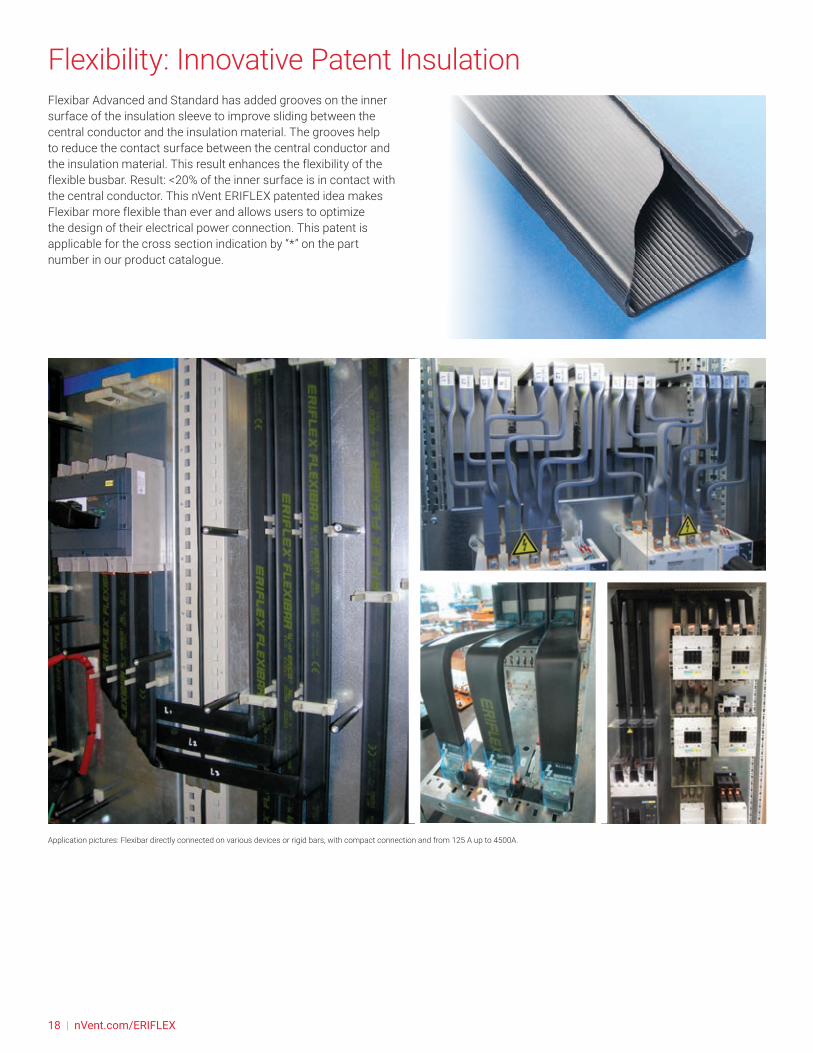
Flexibility: Innovative Patent InsulationFlexibar Advanced and Standard has added grooves on the inner surface of the insulation sleeve to improve sliding between the central conductor and the insulation material. The grooves help to reduce the contact surface between the central conductor and the insulation material. This result enhances the flexibility of the flexible busbar. Result: <20% of the inner surface is in contact with the central conductor. This nVent ERIFLEX patented idea makes Flexibar more flexible than ever and allows users to optimize the design of their electrical power connection. This patent is applicable for the cross section indication by “*” on the part number in our product catalogue.
Application pictures: Flexibar directly connected on various devices or rigid bars, with compact connection and from 125 A up to 4500A.
18 | nVent.com/ERIFLEX
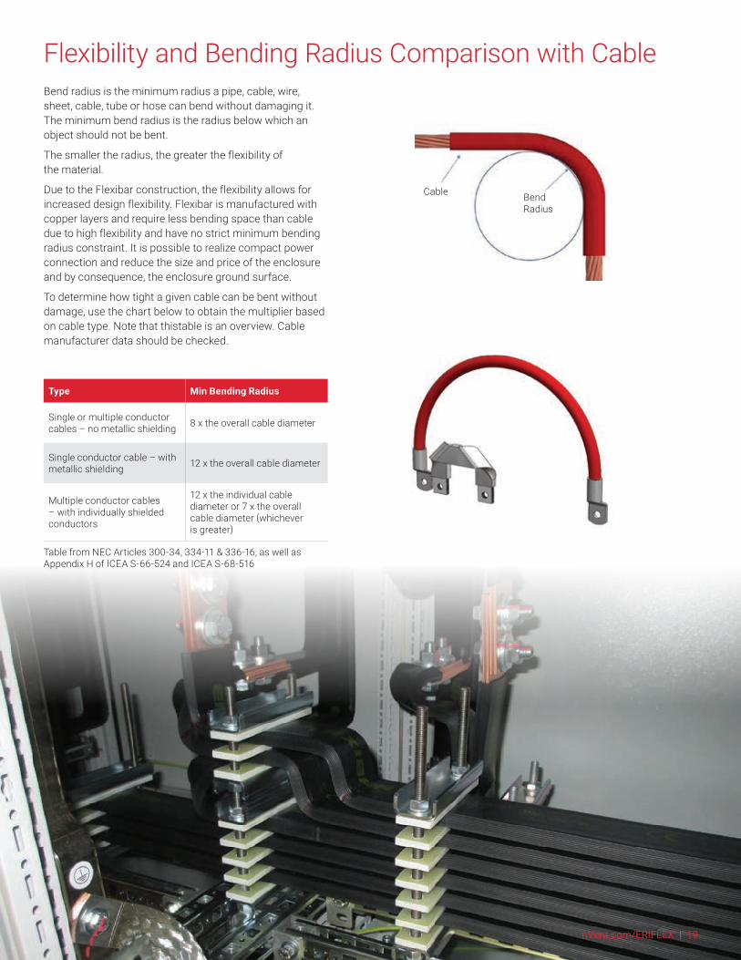
Flexibility and Bending Radius Comparison with CableBend radius is the minimum radius a pipe, cable, wire, sheet, cable, tube or hose can bend without damaging it. The minimum bend radius is the radius below which an object should not be bent.
The smaller the radius, the greater the flexibility of the material.
Due to the Flexibar construction, the flexibility allows for increased design flexibility. Flexibar is manufactured with copper layers and require less bending space than cable due to high flexibility and have no strict minimum bending radius constraint. It is possible to realize compact power connection and reduce the size and price of the enclosure and by consequence, the enclosure ground surface.
To determine how tight a given cable can be bent without damage, use the chart below to obtain the multiplier based on cable type. Note that thistable is an overview. Cable manufacturer data should be checked.
Bend Radius
Cable
Type Min Bending Radius
Single or multiple conductor cables – no metallic shielding 8 x the overall cable diameter
Single conductor cable – with metallic shielding 12 x the overall cable diameter
Multiple conductor cables – with individually shielded conductors
12 x the individual cable diameter or 7 x the overall cable diameter (whichever is greater)
Table from NEC Articles 300-34, 334-11 & 336-16, as well as Appendix H of ICEA S-66-524 and ICEA S-68-516
nVent.com/ERIFLEX | 19

Class II InsulationThe Flexibar Advanced and Standard having Class II insulation certification, according IEC 61439-1 mainly due to:
• High dielectric strength (>20Kv/mm)
• High mechanical resistance (IK 09)
• High temperature resistance (Glow wire test 960°C)
• This certification allows:
• Touching and fixing directly to metal parts permitted (no clearance distance needed).
• Max operating current: up to 100% of the conductor maximum rated temperature (80% without Class II)
TABLE 4 – CONDUCTOR SELECTION AND INSTALLATION REQUIREMENTS (8.6.4) FROM IEC 61 439-1
Type of conductor Requirements
Bare conductors or single-core conductors with basic insulation, for example cables according to IEC 60227-3.
Mutual contact or contact with conductive parts shall be avoided, for example by use of spacers.
Single-core conductors with basic insulation and a maximum permissible conductor operating temperature of at least 90°C, for example cables according to IEC 60245-3, or heat-resistant thermo-plastic (PVC) insulated cables according to IEC 60227-3.
Mutual contact or contact with conductive parts is permitted where there is no applied external pressure. Contact with sharp edges shall be avoided. These conductors may only be loaded such that an operating temperature of 80 % of the maximum permissible conductor operating temperature is not exceeded.
Conductors with basic insulation, for example cables according to IEC 60227-3, having additional secondary insulation, for example individually covered cables with shrink sleeving or individually run cables in plastic conduits.
No additional requirements
Conductors insulated with a very high mechanical additional requirements strength material, for example Ethylene Tetrafluoro Ethylene (ETFE) insulation, or double-insulated conductors with an enhanced outer sheath rated for use up to 3 kV, for example cables according to IEC 60502.
Single or multi-core sheathed cables, for example cables according to IEC 60245-4 or IEC 60227-4.
Insulation none Class II compliant are considered basic insulation. Additionnal requirements are mandatory.
Flexibar Advanced and Standard are considered as a very high mechanical strength material insulation after test (class II). It gives the advantage of no additionnal requirements.
20 | nVent.com/ERIFLEX
Class II InsulationThe chapter 8.6 of internal electricals and connections of the IEC 61439-1 provides strict rules about conductor selection and installation to prevent short-circuit and its consequences. The table 4 defined the requirement of a bare conductor, basic insulated conductor and a reinforced/double insulated conductor (class II) that has to apply in a switchboard.
The advantage of using a reinforced/double insulated conductor is that the table 4 requires “no additional requirement”:
BARE CONDUCTOR:
• Clearance distance and supports / insulators.
Example: solid bars
BASIC INSULATION CONDUCTOR:
• No contact or fixing directly to any metal parts
• operating temperature 80% of the maximum allow by the conductor to prevent the thermal short-circuit damages.
Example: conductors with shrinkable sleeve, one single core cables…
CLASS II CONDUCTOR:
• Touching and fixing directly to metal parts permitted (no clearance distance needed)
• 100% Max operating temperature
105°C for Flexibar Standard
115°C for Flexibar Advanced
If any conductors do not fulfil the requirements, the circuit is subject to additional short-circuit test (10.11).
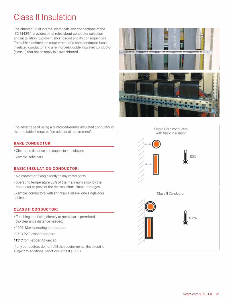
80%
Class II Conductor
Single-Core conductor with basic insulation
100%
80%
Class II Conductor
Single-Core conductor with basic insulation
100%
nVent.com/ERIFLEX | 21

Wrinkle On Insulation
Altitude Effect
Halogen-Free (HF)
For conductors to be used at altitude exceeded 2000 m, it’s necessary to take into the reduction of the dielectric strength and the cooling capacity affected by the air density. The air cooling capability drops along with the altitude increasing, a de-rating factor should be used as the altitude exceeds 2000m. The table below abstracted from DIN 43671 maybe used as a reference for rigid busbar and Flexibar.
Wrinkle appears during bending or folding for the larger cross sections. This phenomenon can be seen especially on Flexibar with 6 and more copper layer.
This deformation allows the insulation to take the position with the lowest level of stress.
Because of the plasticity of the insulation, this typical shape is normal and essential to release the stress of the insulation. This wrinkle does not change any Electrical or mechanical characteristic of the Flexibar.
Altitude (m)
Derating factor
Ampacities (A)
Voltage (V)
> 2000 0.99 0.99
> 3000 0.96 0.96
> 4000 0.9 0.8
HALOGEN-FREE (HF) MATERIAL DOES NOT CONTAIN:
• Fluorine
• Chlorine => (used for PVC)
• Bromine
• Iodine
• Astatine
HALOGEN-FREE (HF) MATERIAL OFFERING:
• Better environmental impact
• Reduces in the quantity of toxic smoke for human
• Reduces corrosive smoke for electrical equipment’s.
HALOGEN-FREE (HF) FLEXIBAR IS TESTED AND COMPLIES WITH:
• IEC® 60754-1 (Test on gases evolved during combustion of materials from cables – Part 1: Determination of the halogen acid gas content)
• IEC® 62821-2 (Electric cables - halogen-free, low smoke, thermoplastic insulated and sheathed cables of rated voltages up to and including 450/750 V)
• UL® 2885 (Outline of Investigation for Acid Gas, Acidity and Conductivity of Combusted Materials)
Flexibar Advanced and Flexibar Summum are halogen-free conductors.
22 | nVent.com/ERIFLEX

Low Smoke (LS)
Flame Retardant (FR)Flame Retardant (FR) material, also called Self-Extinguishing material having the effect of slowing down the spread of fire and according to the international standards such as:
• UL 94V-0
• IEC 60695-2 (Glow Wire test)
SAMPLE OF TEST SEQUENCE AND CLASSIFICATION
LOW SMOKE (LS) MATERIAL OFFERING:
• Improves visibility conditions in case of fire due to lower density of smoke
• people can easily locate the emergency exit
• allows rescue workers to assess an emergency situation
• Less damaging electrical equipment’s.
LOW SMOKE (LS) FLEXIBAR IS TESTED AND COMPLIES WITH:
• IEC® 61034-2 (Measurement of smoke density of cables burning under defined conditions)
• IEC® 60695-6-2 (Fire hazard testing – Part 6-2: Smoke obscuration – Summary and relevance of test methods
• ISO 5659-2 (determination of the optical density of smoke produced from a horizontally positioned test specimen subjected to a specific thermal radiation in a sealed chamber)
• UL® 2885 (Outline of Investigation for Acid Gas, Acidity and Conductivity of Combusted Materials)
Flexibar Advanced is a low smoke conductor.
UL94 - TABLE 8.1
Material Classifications
Criteria Conditions 94V-0 94V-1 94V-2
Afterflame timefor each individual specimen t1 or t2 ≤10s ≤30s ≤30s
Total afterflame time for any condition (t1 plus t2 for the 5 specimens) ≤50s ≤250s ≤250s
Afterflame plus afterglow time for each individual specimen after the second flame application (t2+t3)
≤30s ≤60s ≤60s
Afterflame or afterglow of any specimen up to the holding clamp No No No
Cotton indicator ignited by flaming particles or drops No No Yes
All Flexibar have a flammability rating of UL 94V-0.
In addition, Flexibar Standard and Advanced passed the IEC 60695-2 (Glow Wire test) at higher possible level (960°C) with burning or glow time ≤ 30s with the paper and wood undamaged during test sequence.
1. Specimen
2. Glow wire
3. Flame
4. Tissue
5. Cotton
12
4
IEC
5
3
1
nVent.com/ERIFLEX | 23
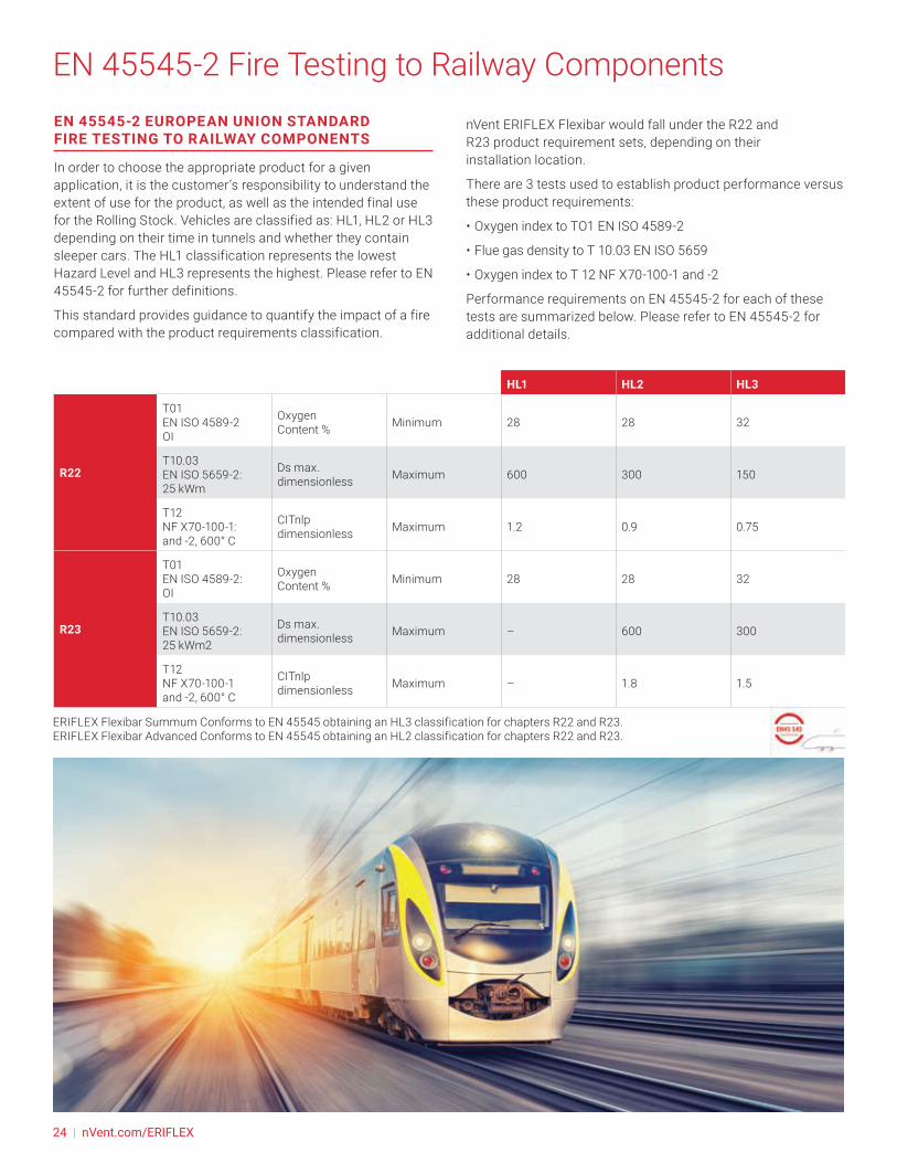
EN 45545-2 Fire Testing to Railway ComponentsEN 45545-2 EUROPEAN UNION STANDARD FIRE TESTING TO RAILWAY COMPONENTS
In order to choose the appropriate product for a given application, it is the customer’s responsibility to understand the extent of use for the product, as well as the intended final use for the Rolling Stock. Vehicles are classified as: HL1, HL2 or HL3 depending on their time in tunnels and whether they contain sleeper cars. The HL1 classification represents the lowest Hazard Level and HL3 represents the highest. Please refer to EN 45545‐2 for further definitions.
This standard provides guidance to quantify the impact of a fire compared with the product requirements classification.
nVent ERIFLEX Flexibar would fall under the R22 and R23 product requirement sets, depending on their installation location.
There are 3 tests used to establish product performance versus these product requirements:
• Oxygen index to TO1 EN ISO 4589-2
• Flue gas density to T 10.03 EN ISO 5659
• Oxygen index to T 12 NF X70-100-1 and -2
Performance requirements on EN 45545-2 for each of these tests are summarized below. Please refer to EN 45545‐2 for additional details.
HL1 HL2 HL3
R22
T01 EN ISO 4589-2 OI
Oxygen Content % Minimum 28 28 32
T10.03 EN ISO 5659-2: 25 kWm
Ds max. dimensionless Maximum 600 300 150
T12 NF X70-100-1: and -2, 600° C
CITnlp dimensionless Maximum 1.2 0.9 0.75
R23
T01 EN ISO 4589-2: OI
Oxygen Content % Minimum 28 28 32
T10.03 EN ISO 5659-2: 25 kWm2
Ds max. dimensionless Maximum – 600 300
T12 NF X70-100-1 and -2, 600° C
CITnlp dimensionless Maximum – 1.8 1.5
ERIFLEX Flexibar Summum Conforms to EN 45545 obtaining an HL3 classification for chapters R22 and R23.ERIFLEX Flexibar Advanced Conforms to EN 45545 obtaining an HL2 classification for chapters R22 and R23.
24 | nVent.com/ERIFLEX

Certifications for Marine & Offshore
WORLDWIDE CERTIFICATION
nVent ERIFLEX is a trusted partner for assistance with designing your electrical cabinet. Our range of world-class certifications include:
• nVent ERIFLEX Flexibar Advanced: IEC 61 439-1 and UL 67 / UL 758
• Full nVent ERIFLEX product range is compliant with RoHS and CE
NVENT ERIFLEX ADVANCED TECHNOLOGY CERTIFICATIONS
• Halogen-free: IEC 60754-1 and/or UL 2885 standards
• Low smoke: UL 2885 and IEC 60754-2
• Flame retardant: IEC 60695-2-11 Glow Wire test 960°C and/or UL 94-V0
• UV resistance: UL 2556 and UL 854
Marine & Offshore Certifications
nVent ERIFLEX Products
Flexibar Advanced þ þ
Flexibar Standard þ þ
NVENT ERIFLEX PRODUCT OFFERING.
SPACE SAVINGS TIME SAVINGS
SAFER SOLUTIONSRELIABILITY
nVent ERIFLEX Advanced Technology PVC Insulation
In the marine and offshore market, space is critical for electrical cabinets and connections. Thanks to the innovative technology from nVent ERIFLEX you can reduce your footprint of your electrical cabinet.
20% volume reduction
The design of an electrical panel is important. nVent ERIFLEX helps to simplify the connection with solutions that reduce labor time.
Our products are easy to shape and enable more efficient visual inspection.
To enhance safety and reliability in enclosed spaces, nVent ERIFLEX has developed a complete and reliable range that uses tinned plate material for better corrosion resistance.
Additionally, our unique products help provide better access and improved vibration resistance.
Cabinet with cables
nVent ERIFLEX Flexibar
Advanced
Catering to the unique needs of the marine and offshore market, the latest generation of nVent ERIFLEX insulation material combines the following features:
• Low smoke, halogen-free, flame retardant
• High temperature resistant
• Tin-plated
nVent.com/ERIFLEX | 25
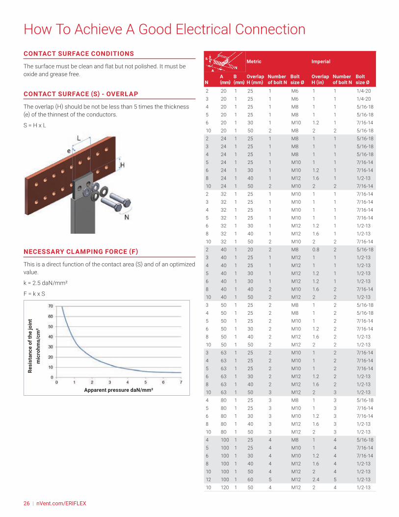
How To Achieve A Good Electrical ConnectionCONTACT SURFACE CONDITIONS
The surface must be clean and flat but not polished. It must be oxide and grease free.
CONTACT SURFACE (S) - OVERLAP
The overlap (H) should be not be less than 5 times the thickness (e) of the thinnest of the conductors.
S = H x L
NECESSARY CLAMPING FORCE (F)
This is a direct function of the contact area (S) and of an optimized value.
k = 2.5 daN/mm²
F = k x S
Resi
stan
ce o
f the
join
tm
icro
hms/
cm²
Apparent pressure daN/mm²
Metric Imperial
Overlap H (mm)
Number of bolt N
Bolt size Ø
Overlap H (in)
Number of bolt N
Bolt size ØN
A (mm)
B (mm)
2 20 1 25 1 M6 1 1 1/4-203 20 1 25 1 M6 1 1 1/4-204 20 1 25 1 M8 1 1 5/16-185 20 1 25 1 M8 1 1 5/16-186 20 1 30 1 M10 1.2 1 7/16-1410 20 1 50 2 M8 2 2 5/16-182 24 1 25 1 M8 1 1 5/16-183 24 1 25 1 M8 1 1 5/16-184 24 1 25 1 M8 1 1 5/16-185 24 1 25 1 M10 1 1 7/16-146 24 1 30 1 M10 1.2 1 7/16-148 24 1 40 1 M12 1.6 1 1/2-1310 24 1 50 2 M10 2 2 7/16-142 32 1 25 1 M10 1 1 7/16-143 32 1 25 1 M10 1 1 7/16-144 32 1 25 1 M10 1 1 7/16-145 32 1 25 1 M10 1 1 7/16-146 32 1 30 1 M12 1.2 1 1/2-138 32 1 40 1 M12 1.6 1 1/2-1310 32 1 50 2 M10 2 2 7/16-142 40 1 20 2 M8 0.8 2 5/16-183 40 1 25 1 M12 1 1 1/2-134 40 1 25 1 M12 1 1 1/2-135 40 1 30 1 M12 1.2 1 1/2-136 40 1 30 1 M12 1.2 1 1/2-138 40 1 40 2 M10 1.6 2 7/16-1410 40 1 50 2 M12 2 2 1/2-133 50 1 25 2 M8 1 2 5/16-184 50 1 25 2 M8 1 2 5/16-185 50 1 25 2 M10 1 2 7/16-146 50 1 30 2 M10 1.2 2 7/16-148 50 1 40 2 M12 1.6 2 1/2-1310 50 1 50 2 M12 2 2 1/2-133 63 1 25 2 M10 1 2 7/16-144 63 1 25 2 M10 1 2 7/16-145 63 1 25 2 M10 1 2 7/16-146 63 1 30 2 M12 1.2 2 1/2-138 63 1 40 2 M12 1.6 2 1/2-1310 63 1 50 3 M12 2 3 1/2-134 80 1 25 3 M8 1 3 5/16-185 80 1 25 3 M10 1 3 7/16-146 80 1 30 3 M10 1.2 3 7/16-148 80 1 40 3 M12 1.6 3 1/2-1310 80 1 50 3 M12 2 3 1/2-134 100 1 25 4 M8 1 4 5/16-185 100 1 25 4 M10 1 4 7/16-146 100 1 30 4 M10 1.2 4 7/16-148 100 1 40 4 M12 1.6 4 1/2-1310 100 1 50 4 M12 2 4 1/2-1312 100 1 60 5 M12 2.4 5 1/2-1310 120 1 50 4 M12 2 4 1/2-13
26 | nVent.com/ERIFLEX

How To Achieve A Good Electrical Connection• Class 8.8 ZN8C or SAE Grade 5 hardware can be used except
where otherwise designated by the designer of the pieces installed
• Contact/Belleville and flat washers to provide resistance to vibration
• Slotted holes are acceptable in applications where additional forming is anticipated during installation
• See our web site, nVent.com/ERIFLEX to consult our metric and imperial nuts, bolt and washers contact kits.
CLAMPING TORQUE CALCULATION
Use a class 8.8 ZN8C zinc plated bolt or a class coated bichromated bolt (SAE Grade 5), using “Contact/Belleville” and “Flat” washers tightened with a torque wrench, without lubrication.
Note: Belleville washers also called “Contact Disc Springs”.
Metric (with contact washer)
Bolt size Ø M6 M8 M10 M12 M14 M16
F (daN) 800 1450 2300 3700 4400 6000
Clamping Torque (Nm) 13 30 60 110 174 274
Imperial (with Belleville washer)
Bolt size Ø 1/4-20
5/16-18
3/8-16
7/16-14
1/2-13
9/16-12
5/8-11
Clamping Torque (foot-pounds)
9 18 31 50 75 110 150
nVent.com/ERIFLEX | 27
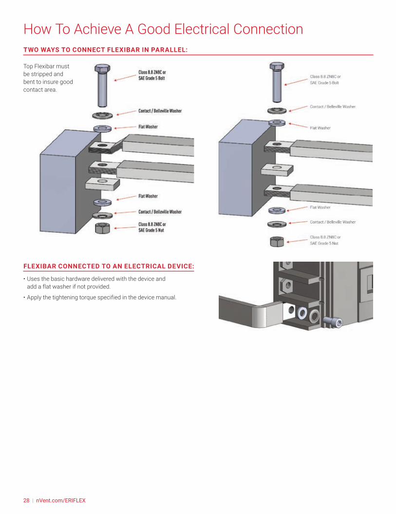
How To Achieve A Good Electrical Connection
FLEXIBAR CONNECTED TO AN ELECTRICAL DEVICE:
• Uses the basic hardware delivered with the device and add a flat washer if not provided.
• Apply the tightening torque specified in the device manual.
TWO WAYS TO CONNECT FLEXIBAR IN PARALLEL:
Top Flexibar must be stripped and bent to insure good contact area.
28 | nVent.com/ERIFLEX
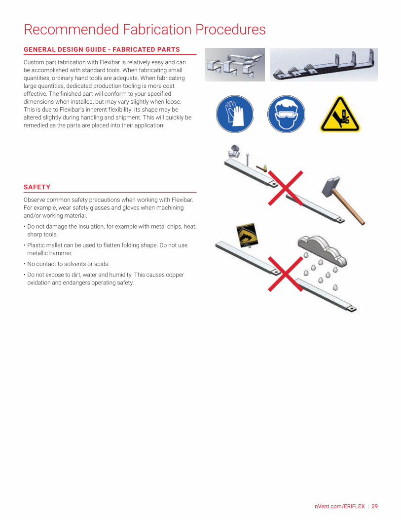
Recommended Fabrication ProceduresGENERAL DESIGN GUIDE - FABRICATED PARTS
Custom part fabrication with Flexibar is relatively easy and can be accomplished with standard tools. When fabricating small quantities, ordinary hand tools are adequate. When fabricating large quantities, dedicated production tooling is more cost effective. The finished part will conform to your specified dimensions when installed, but may vary slightly when loose. This is due to Flexibar’s inherent flexibility; its shape may be altered slightly during handling and shipment. This will quickly be remedied as the parts are placed into their application.
SAFETY
Observe common safety precautions when working with Flexibar. For example, wear safety glasses and gloves when machining and/or working material.
• Do not damage the insulation, for example with metal chips, heat, sharp tools.
• Plastic mallet can be used to flatten folding shape. Do not use metallic hammer.
• No contact to solvents or acids.
• Do not expose to dirt, water and humidity. This causes copper oxidation and endangers operating safety.
nVent.com/ERIFLEX | 29
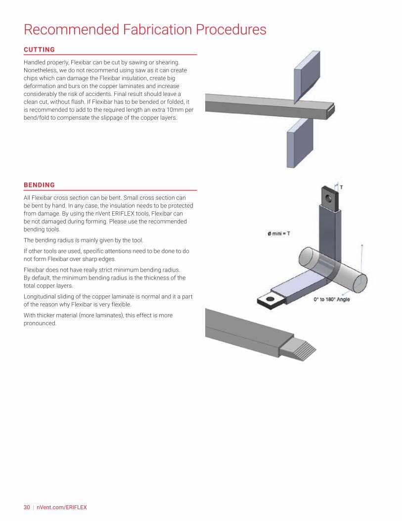
Recommended Fabrication ProceduresCUTTING
Handled properly, Flexibar can be cut by sawing or shearing. Nonetheless, we do not recommend using saw as it can create chips which can damage the Flexibar insulation, create big deformation and burs on the copper laminates and increase considerably the risk of accidents. Final result should leave a clean cut, without flash. If Flexibar has to be bended or folded, it is recommended to add to the required length an extra 10mm per bend/fold to compensate the slippage of the copper layers.
BENDING
All Flexibar cross section can be bent. Small cross section can be bent by hand. In any case, the insulation needs to be protected from damage. By using the nVent ERIFLEX tools, Flexibar can be not damaged during forming. Please use the recommended bending tools.
The bending radius is mainly given by the tool.
If other tools are used, specific attentions need to be done to do not form Flexibar over sharp edges.
Flexibar does not have really strict minimum bending radius. By default, the minimum bending radius is the thickness of the total copper layers.
Longitudinal sliding of the copper laminate is normal and it a part of the reason why Flexibar is very flexible.
With thicker material (more laminates), this effect is more pronounced.
30 | nVent.com/ERIFLEX

Recommended Fabrication ProceduresTWISTING
All Flexibar cross section can be twisted.
For twisting, use the same recommendation as for bending.
Flexibar can be twisted along its length. The best results (optimization of the strength applied and the compactness) are obtained when the twists are 90 degrees or less and with a typical length of twisting between 3 to 4 times the total busbar width. This distance must not be less than 2.5 with the traditional tools. Ensure when rotating by 90° that the necessary length is equivalent to 2.5 times minimum the busbar width. It is recommended that the part is not twisted greater than 100° degres.
Lateral and longitudinal sliding of the copper laminate is normal and it a part of the reason why Flexibar is very flexible.
With thicker material (more laminates), this effect is more pronounced.
By using the nVent ERIFLEX tools, Flexibar can be not damaged during forming. Please use, the recommended nVent ERIFLEX twisting tool.
Flexibar Summum cannot be twisted with the nVent ERIFLEX twisting tool. Contact directly the nVent ERIFLEX representative to sub-contract this twisting into our internal workshop.
FOLDING
All Flexibar cross section can be folded. This operation can be done by hand for small cross section. For medium and big cross section, use the Folding tool from nVent ERIFLEX.
By using the nVent ERIFLEX tools, Flexibar can be not damaged during forming. Please use the recommended nVent ERIFLEX folding tools.
The bending radius is mainly given by the tool.
If other tools are used, specific attentions need to be done to do not form Flexibar over sharp edges.
Folding flatten with a soft hammer
nVent.com/ERIFLEX | 31
Recommended Fabrication ProceduresFlexibar does not have really strict minimum bending radius. By default, the minimum bending radius is the thickness of the total copper layers.
Lateral and longitudinal sliding of the copper laminate is normal and it a part of the reason why Flexibar is very flexible.
With thicker material (more laminates), this effect is more pronounced.
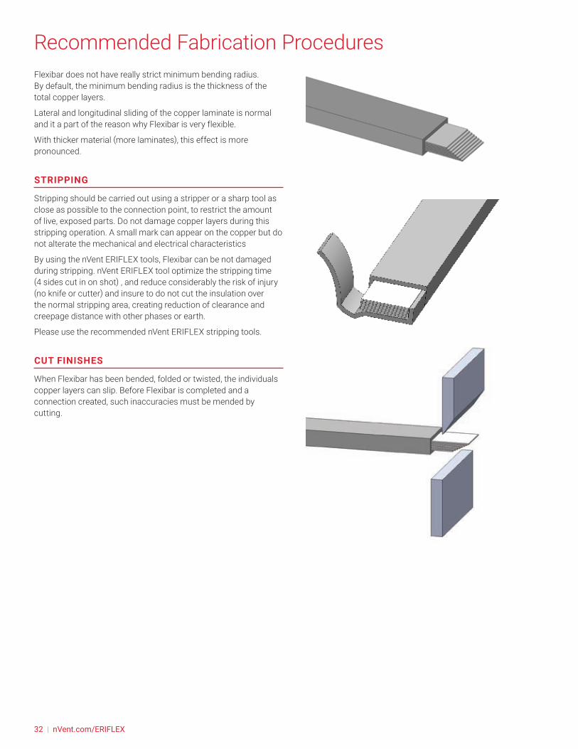
STRIPPING
Stripping should be carried out using a stripper or a sharp tool as close as possible to the connection point, to restrict the amount of live, exposed parts. Do not damage copper layers during this stripping operation. A small mark can appear on the copper but do not alterate the mechanical and electrical characteristics
By using the nVent ERIFLEX tools, Flexibar can be not damaged during stripping. nVent ERIFLEX tool optimize the stripping time (4 sides cut in on shot) , and reduce considerably the risk of injury (no knife or cutter) and insure to do not cut the insulation over the normal stripping area, creating reduction of clearance and creepage distance with other phases or earth.
Please use the recommended nVent ERIFLEX stripping tools.
CUT FINISHES
When Flexibar has been bended, folded or twisted, the individuals copper layers can slip. Before Flexibar is completed and a connection created, such inaccuracies must be mended by cutting.
32 | nVent.com/ERIFLEX
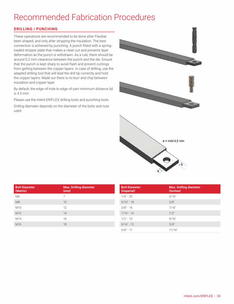
Recommended Fabrication ProceduresDRILLING / PUNCHING
These operations are recommended to be done after Flexibar been shaped, and only after stripping the insulation. The best connection is achieved by punching. A punch fitted with a spring-loaded stripper plate that makes a clean cut and prevents layer deformation as the punch is withdrawn. As a rule, there should be around 0.2 mm clearance between the punch and the die. Ensure that the punch is kept sharp to avoid flash and prevent cuttings from getting between the copper layers. In case of drilling, use the adapted drilling tool that will lead the drill tip correctly and hold the copper layers. Made sur there is no burr and chip between insulation and copper layer.
By default, the edge-of-hole to edge-of-part minimum distance (e) is 4.5 mm.
Please use the nVent ERIFLEX drilling tools and punching tools.
Drilling diameter depends on the diameter of the bolts and nuts used.
Bolt Diameter (Metric)
Max. Drilling diameter (mm)
M6 7
M8 10
M10 12
M12 14
M14 16
M16 18
Bolt Diameter (Imperial)
Max. Drilling diameter (Inches)
1/4" - 20 5/16"
5/16" - 18 3/8"
3/8" - 16 7/16"
7/16" - 14 1/2"
1/2" - 13 9/16"
9/16" - 12 5/8"
5/8" - 11 11/16"
nVent.com/ERIFLEX | 33
Recommended Fabrication ProceduresFABRICATION STEPS ORDER
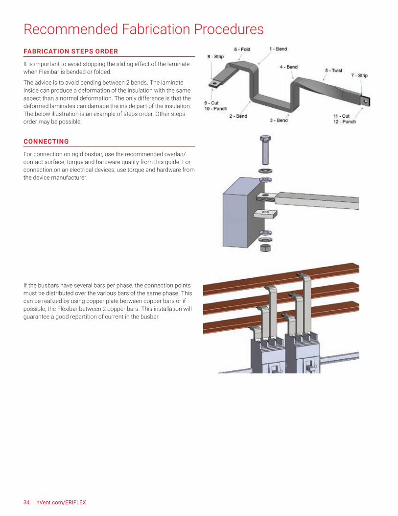
It is important to avoid stopping the sliding effect of the laminate when Flexibar is bended or folded.
The advice is to avoid bending between 2 bends. The laminate inside can produce a deformation of the insulation with the same aspect than a normal deformation. The only difference is that the deformed laminates can damage the inside part of the insulation. The below illustration is an example of steps order. Other steps order may be possible.
CONNECTING
For connection on rigid busbar, use the recommended overlap/contact surface, torque and hardware quality from this guide. For connection on an electrical devices, use torque and hardware from the device manufacturer.
If the busbars have several bars per phase, the connection points must be distributed over the various bars of the same phase. This can be realized by using copper plate between copper bars or if possible, the Flexibar between 2 copper bars. This installation will guarantee a good repartition of current in the busbar.
34 | nVent.com/ERIFLEX

Recommended Fabrication ProceduresFLEXIBAR CONNECTION ON MCCB
The below table provides some guidance regarding possible Flexibar cross section to use for some MCCB (Molded Case Circuit Breaker).
MCCB from this list are:
• IEC version
• Front access connection, without accessory
• Fixed version
This recommendation table taking in account:
• Width of the MCCB palm
• Rated Current of the MCCB.
This table do not taking in account some specific installation environment, like ambient temperature, protection level of enclosure, altitude, frequency…
Some MCCB may need more important cross section in function of the MCCB Power dissipation. In some case, increase the Flexibar cross section may be necessary to support MCCB heating dissipation. It is therefore necessary to respect the instructions provided by the electrical device manufacturer.
Rated Current of the circuit breaker 1600A 1250A 1000A 800A 630A 500A 400A 350A 300A 250A 125/160A
Schneider Electric NS 1600 NS 1250 NS 1000 NS 800 NSX 630 NSX 630 NSX 400 NSX 400 NSX 400 NSX 250 NSA NG 125
NSX 100 NSX 160
Flexibar Section
6 x 50 x 1 (x2)
10 x 50 x 1 8 x 50 x 1 5 x 50 x 1 6 x 32 x 1 4 x 32 x 1 3 x 32 x 1 2 x 32 x 1 2 x 32 x 1 2 x 24 x 1 6 x 9 x 0,8 2 x 20 x 1
ABB T max T7 T max T7 T max T6 T max T6 T max T5 T max T5 T max T5 Tmax T4 Tmax T4 Tmax T3/XT3/XT4
Tmax T1/T2/XT2 Tmax XT1
Flexibar Section
6 x 50 x 1 (x2)
10 x 50 x 1
10 x 40 x 1 6 x 40 x 1 6 x 32 x 1 4 x 32 x 1 3 x 32 x 1 2 x 24 x 1 2 x 24 x 1 2 x 24 x 1 2 x 20 x 1 2 x 15,5 x
0,8General Electric FK 1600 FK 1250 FK 1250 FK 800 FG 630 FG 630 FG 400 FG 400 FG 400 FE 250 FE 160 FD 160Flexibar Section
6 x 50 x 1 (x2)
10 x 50 x 1 8 x 50 x 1 5 x 50 x 1 6 x 32 x 1 4 x 32 x 1 3 x 32 x 1 2 x 32 x 1 2 x 32 x 1 2 x 24 x 1 2 x 20 x 1 6 x 9 x 0,8
Siemens VL1600 3VL8
VL1250 3VL7
VL1250 3VL7
VL800 3VL6
VL630 3VL5
VL630 3VL5
VL400 3VL4
VL400 3VL4
VL400 3VL4
VL250 3VL3
VL160 3VL2
VL160X 3VL1
Flexibar Section
6 x 50 x 1 (x2)
10 x 50 x 1 8 x 50 x 1 6 x 40 x 1 5 x 40 x 1 3 x 40 x 1 3 x 32 x 1 2 x 32 x 1 2 x 32 x 1 2 x 24 x 1 2 x 20 x 1 2 x 15,5 x
0,8Eaton / Moeller NZM4 NZM4 NZM4 NZM4 NZM3 NZM3 NZM3 NZM3 NZM3 NZM2 NZM1Flexibar Section
6 x 50 x 1 (x2)
10 x 50 x 1 8 x 50 x 1 5 x 50 x 1 6 x 32 x 1 4 x 32 x 1 3 x 32 x 1 2 x 32 x 1 2 x 32 x 1 2 x 24 x 1 6 x 9 x 0,8
Legrand / Bticino DPX 1600 DPX 1600 DPX 1600 DPX 1600 DPX 630 DPX 630 DPX 630 DPX 630 DPX 630 DPX 250 & (DPX3 250)
DPX 160 & (DPX3 160) DPX 125
Flexibar Section
6 x 50 x 1 (x2)
10 x 50 x 1 8 x 50 x 1 5 x 50 x 1 6 x 32 x 1 4 x 32 x 1 3 x 32 x 1 2 x 32 x 1 2 x 32 x 1 2 x 24 x 1 2 x 15,5 x
0,8 6 x 9 x 0,8
Application pictures: Flexibar directly connected on MCCB’s front access connection.
nVent.com/ERIFLEX | 35
Recommended Fabrication ProceduresACCESSORIES AND SOLUTIONS FOR CONNECTION
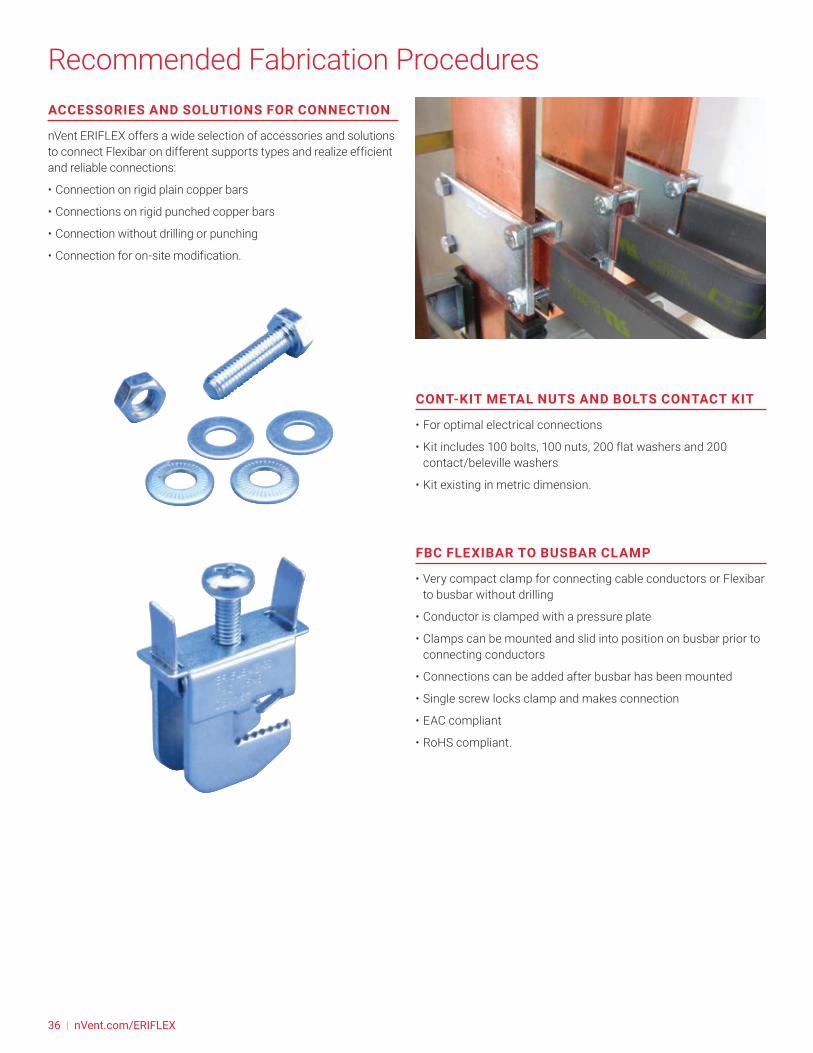
nVent ERIFLEX offers a wide selection of accessories and solutions to connect Flexibar on different supports types and realize efficient and reliable connections:
• Connection on rigid plain copper bars
• Connections on rigid punched copper bars
• Connection without drilling or punching
• Connection for on-site modification.
CONT-KIT METAL NUTS AND BOLTS CONTACT KIT
• For optimal electrical connections
• Kit includes 100 bolts, 100 nuts, 200 flat washers and 200 contact/beleville washers
• Kit existing in metric dimension.
FBC FLEXIBAR TO BUSBAR CLAMP
• Very compact clamp for connecting cable conductors or Flexibar to busbar without drilling
• Conductor is clamped with a pressure plate
• Clamps can be mounted and slid into position on busbar prior to connecting conductors
• Connections can be added after busbar has been mounted
• Single screw locks clamp and makes connection
• EAC compliant
• RoHS compliant.
36 | nVent.com/ERIFLEX
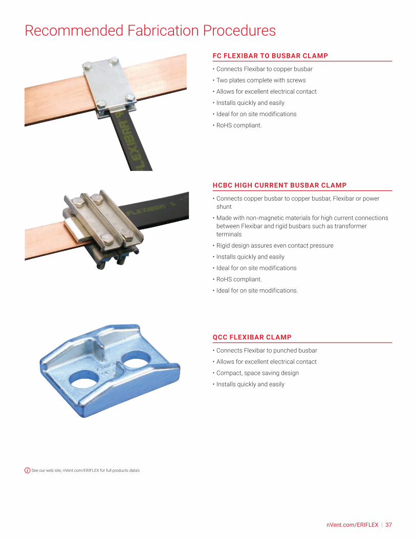
Recommended Fabrication ProceduresFC FLEXIBAR TO BUSBAR CLAMP
• Connects Flexibar to copper busbar
• Two plates complete with screws
• Allows for excellent electrical contact
• Installs quickly and easily
• Ideal for on site modifications
• RoHS compliant.
HCBC HIGH CURRENT BUSBAR CLAMP
• Connects copper busbar to copper busbar, Flexibar or power shunt
• Made with non-magnetic materials for high current connections between Flexibar and rigid busbars such as transformer terminals
• Rigid design assures even contact pressure
• Installs quickly and easily
• Ideal for on site modifications
• RoHS compliant.
• Ideal for on site modifications.
QCC FLEXIBAR CLAMP
• Connects Flexibar to punched busbar
• Allows for excellent electrical contact
• Compact, space saving design
• Installs quickly and easily
See our web site, nVent.com/ERIFLEX for full products data’s
nVent.com/ERIFLEX | 37
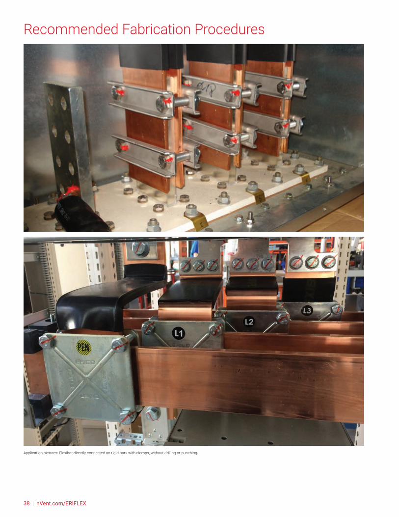
Recommended Fabrication Procedures
Application pictures: Flexibar directly connected on rigid bars with clamps, without drilling or punching.
38 | nVent.com/ERIFLEX

Recommended Fabrication ProceduresFLEXIBAR DIRECT CONNECTION ON POWER & DISTRIBUTION BLOCKS
nVent ERIFLEX offers a wide selection of compact halogen-free power & flame retardant blocks and single pole, two poles, and four pole distribution blocks and a complete range of assembly support products for easy fastening to DIN rails or steel sheet. The blocks offer easy assembly with visual inspection to allow for confirmation of connections to a wide range of conductors including Flexibar. The high fill ratio ensures optimal electrical connectivity even in tight assemblies.
SINGLE POLE DISTRIBUTION BLOCKS (UD SERIES)
• Directly connect Flexibar on line side
• Tinned copper or tinned aluminum block allows for copper or aluminum conductor connections
• Screw retaining cover is hinged and removable
• Design allows for visual inspection of conductor and confirmation of connection
• Stackable for building multi-pole power blocks
• Easily clips onto DIN rail or mounts to panel with screws
• 95% fill ratio
• Halogen-free a part of the nVent ERIFLEX Advanced Technology range
• RoHS compliant.
• On some model IP 20 slider to ensure positioning IP 20 finger safe features with flat conductors
POWER BLOCKS (SB SERIES)
• Directly connect Flexibar or insulated power braid on line side
• Compact power block with high short circuit current rating
• Tinned copper or aluminum block allows for copper or aluminum conductor connections
• Screw retaining cover is hinged and removable
• Design allows for visual inspection of conductor and confirmation of connection
• Stackable for building multi-pole power blocks
• Easily clips onto DIN rail or mounts to panel with screws
• Voltage detection and measurement connection
• 95% fill ratio
• Halogen-free a part of the nVent ERIFLEX Advanced Technology range
• RoHS compliant.
• On some model : IP 20 slider to ensure positioning IP 20 finger safe features with flat conductors
nVent.com/ERIFLEX | 39

Recommended Fabrication ProceduresPOWER TERMINALS (SBLL & SBLT SERIES)
• Tinned copper block allows for copper or aluminum conductor connections
• Accessible studs allow for easy connection of sections of Flexibar or other conductors
• Design allows for visual inspection of conductor and confirmation of connection
• Adjustable transparent cover
• Stackable for building multi-pole power blocks
• Easily clips onto DIN rail or mounts to panel with screws
• SBLEC power terminals fixing accessory required for direct panel mount
• Halogen-free a part of the nVent ERIFLEX Advanced Technology range
• RoHS compliant.
TDL COMPACT FOUR POLE DISTRIBUTION BLOCK, 400 A
• Connect Flexibar, insulated braided conductor or cable with lug on line side
• Tinned copper bars allows for copper or aluminum cable
• Transparent protection covers
• Easy and safe connections
• Easily clips onto DIN rail or mounts to panel with screws
• Solid bars provide reliability
• Input separated from outputs
• Supports wiring from both sides
• Design allows for visual inspection of conductor and confirmation of connection
• Large end terminals
• High percentange of fill ratio
• Wiring with or without terminal
• Halogen-free a part of the nVent ERIFLEX Advanced Technology range
• RoHS compliant.See our web site, nVent.com/ERIFLEX for full products data’s
40 | nVent.com/ERIFLEX
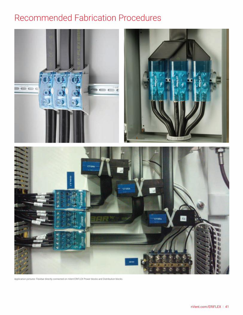
Recommended Fabrication Procedures
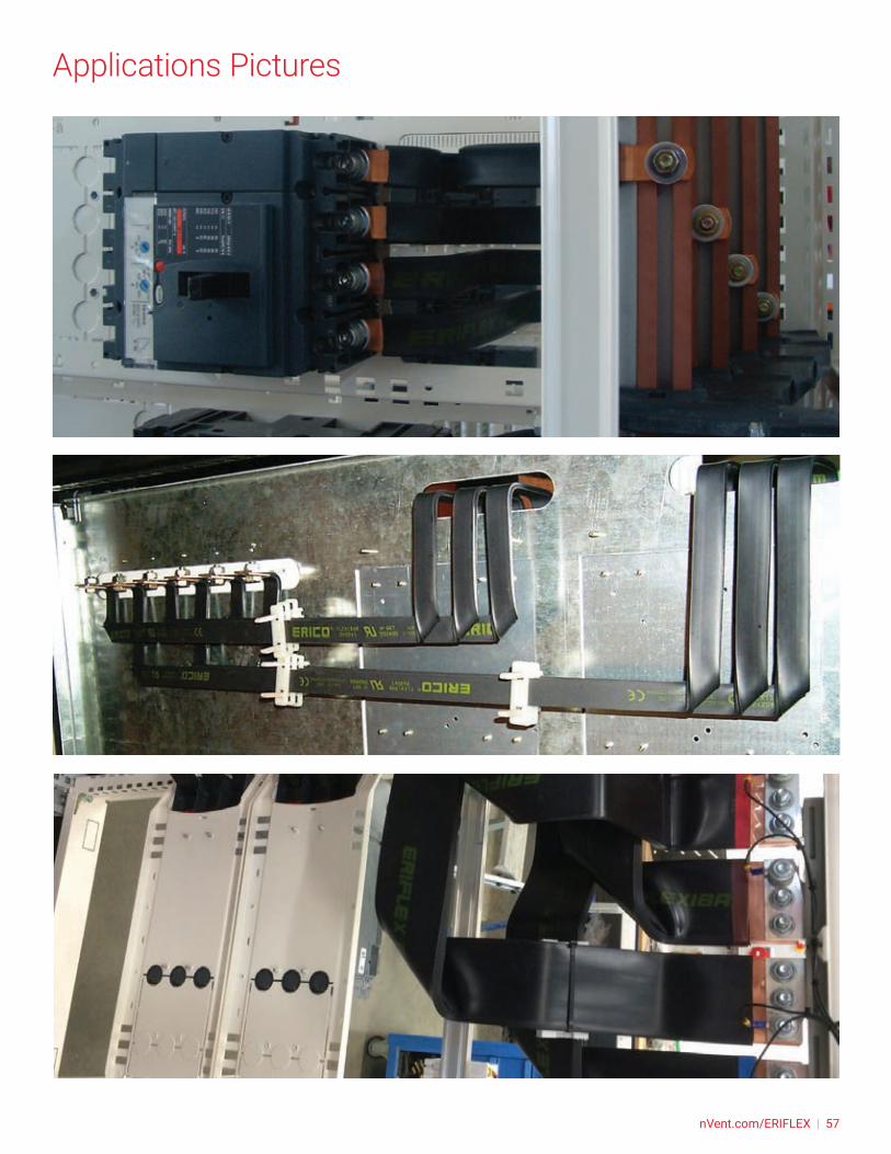
Application pictures: Flexibar directly connected on nVent ERIFLEX Power blocks and Distribution blocks.
nVent.com/ERIFLEX | 41
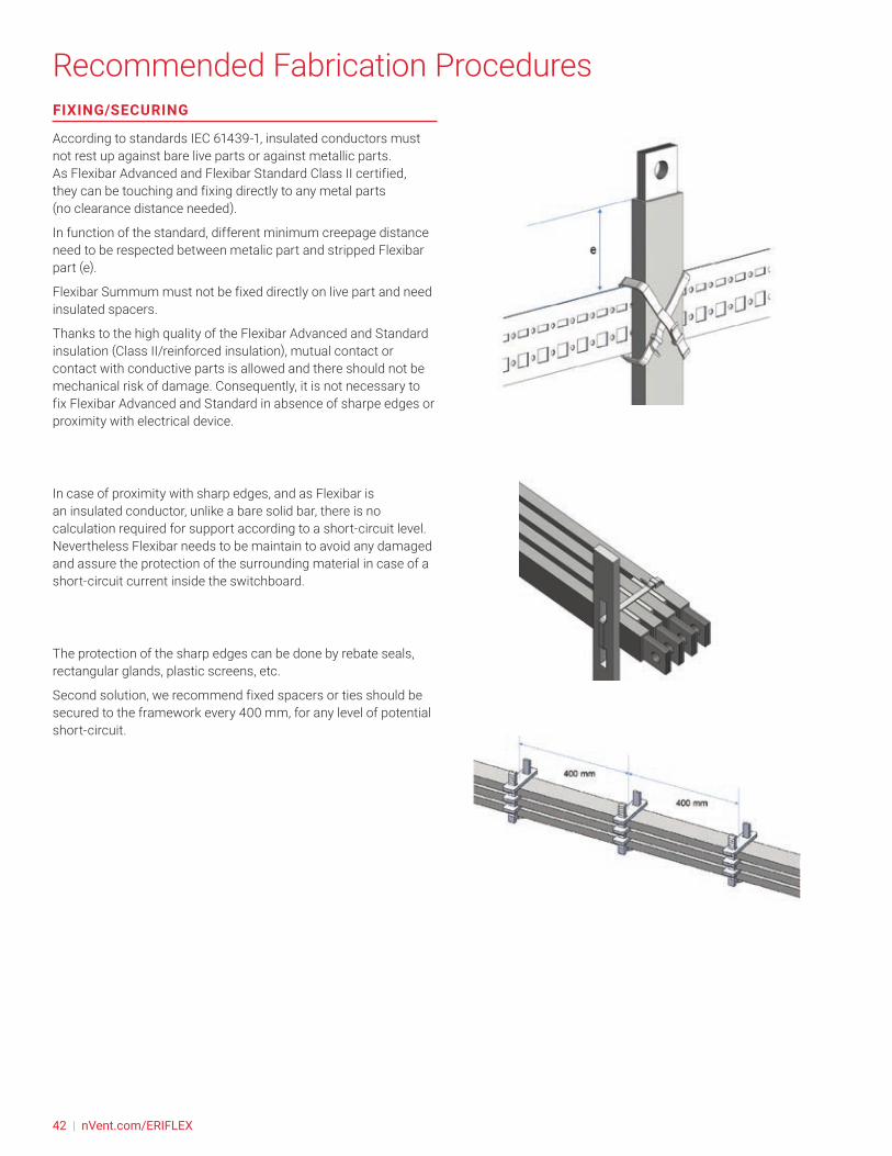
FIXING/SECURING
According to standards IEC 61439-1, insulated conductors must not rest up against bare live parts or against metallic parts. As Flexibar Advanced and Flexibar Standard Class II certified, they can be touching and fixing directly to any metal parts (no clearance distance needed).
In function of the standard, different minimum creepage distance need to be respected between metalic part and stripped Flexibar part (e).
Flexibar Summum must not be fixed directly on live part and need insulated spacers.
Thanks to the high quality of the Flexibar Advanced and Standard insulation (Class II/reinforced insulation), mutual contact or contact with conductive parts is allowed and there should not be mechanical risk of damage. Consequently, it is not necessary to fix Flexibar Advanced and Standard in absence of sharpe edges or proximity with electrical device.
In case of proximity with sharp edges, and as Flexibar is an insulated conductor, unlike a bare solid bar, there is no calculation required for support according to a short-circuit level. Nevertheless Flexibar needs to be maintain to avoid any damaged and assure the protection of the surrounding material in case of a short-circuit current inside the switchboard.
The protection of the sharp edges can be done by rebate seals, rectangular glands, plastic screens, etc.
Second solution, we recommend fixed spacers or ties should be secured to the framework every 400 mm, for any level of potential short-circuit.
Recommended Fabrication Procedures
42 | nVent.com/ERIFLEX

Recommended Fabrication ProceduresWe advise installers to use nVent ERIFLEX spacers (FS, RFS, UFS kit) which improve the aesthetics global feature.
The last spacer should be located as close as possible to the device connection.
In case of plastic tie used, we recommend:
• Tie type 4.5mm minimum width.
• Do not tight tie with tool, but only gently by hand in order to not compromise insulation integrity.
• Do not put tie collar junction on Flexibar corners, but on the plane surface.
• Weight of supported Flexibar should be below tie mechanical resistance.
• If tie need to be removed after Flexibar have been submitted to the temperature close to the maximum admissible of the insulation, a visual inspection need to be performed to check insulation integrity.
• The last tie should be located as close as possible to the device connection.
In cases where several Flexibar products are installed in parallel, a minimum distance of a few millimeters is recommended for air cooling. To ensure that conductors are properly ventilated, a space should be left between the flexible bars, at each tie or spacer. Multiple Flexibar per phase shall be spaced with a min adjacent distance of 4mm for ventilation.
Note: The cooling is better for a rectangular bar standing on its edge.
nVent.com/ERIFLEX | 43
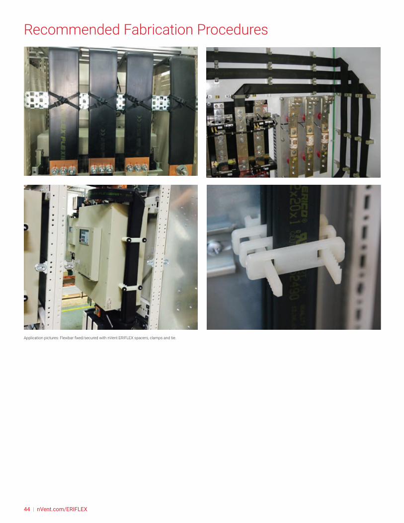
Recommended Fabrication Procedures
Application pictures: Flexibar fixed/secured with nVent ERIFLEX spacers, clamps and tie.
44 | nVent.com/ERIFLEX

Recommended Fabrication ProceduresACCESSORIES AND SOLUTION FOR FIXING/SECURING
• nVent ERIFLEX offers a wide selection of accessories and solutions to fix and secure Flexibar on edge position or flat position. Those clamps allow:
• Fixing/Securing without damaging the insulation
• Fixing/Securing with correct spacing for optimum cooling
• Fixing/Securing multiple Flexibar in parallel.
UFS SUPPORT KIT
• Kit includes one rail and 24 retaining blocks
• Create up to three 650 mm (25.6”) supports capable of holding four Flexibar
• Retaining blocks are halogen-free
• RoHS compliant
• Conductor thickness: 2 - 8 mm
• Conductor width: 15.5 – 120 mm
• Recommended distance between supports is 400 mm.
FS SPACER CLAMP
• Provides support for Flexibar without damaging the insulation
• Ensures correct spacing for optimum cooling
• Supports up to four conductors in parallel
• Easy to install
• Spacers are halogen-free
• RoHS compliant
• Conductor width: 40 – 100 mm
• Recommended distance between supports is 400 mm.
nVent.com/ERIFLEX | 45

Recommended Fabrication ProceduresFS SPACER CLAMP, SNAP CLOSE
• Provides support for Flexibar without damaging the insulation
• Ensures correct spacing for optimum cooling
• Supports up to four conductors in parallel
• Easy to install
• Halogen-free
• Conductor width: 15.5 – 32 mm
• RoHS compliant
• Recommended distance between supports is 400 mm.
RFS REINFORCED SUPPORT
• Supports up to eight conductors in parallel
• Ensures correct spacing for optimum cooling
• Easy to install
• Spacers are halogen-free
• RoHS compliant
• Conductor width: 40 – 100 mm
• Recommended distance between supports is 400 mm.
Application pictures: Flexibar fixed/secured with nVent ERIFLEX spacers and clamps.
See our web site, nVent.com/ERIFLEX for full products data’s
46 | nVent.com/ERIFLEX
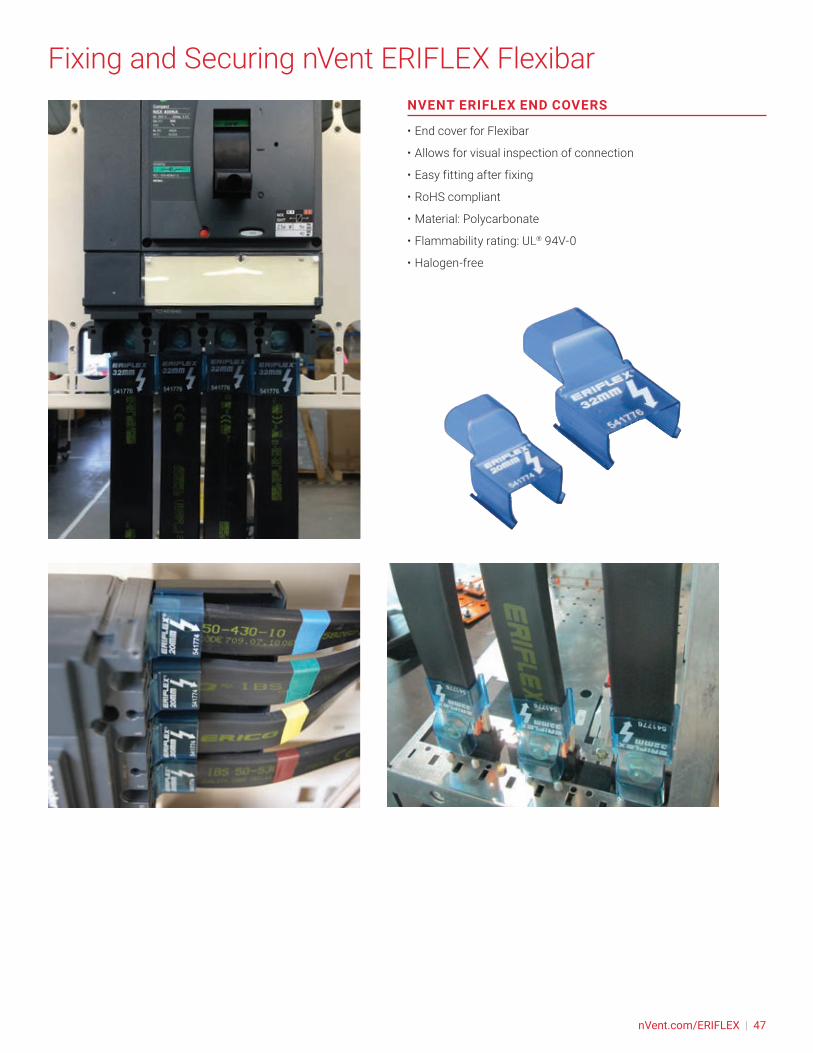
Fixing and Securing nVent ERIFLEX FlexibarNVENT ERIFLEX END COVERS
• End cover for Flexibar
• Allows for visual inspection of connection
• Easy fitting after fixing
• RoHS compliant
• Material: Polycarbonate
• Flammability rating: UL® 94V-0
• Halogen-free
nVent.com/ERIFLEX | 47
Recommended Fabrication Tools
FUNCTION - CUTTING
NVENT ERIFLEX OFFERS A WIDE SELECTION OF MANUAL OR HYDRAULIC TOOLS FOR FLEXIBAR FABRICATION.
Those dedicated Flexibar tools will help you to:
• Work within safe environment
• Determine the correct position of the cut, bend, fold, punch…
• Minimize the deformation of the laminate
• Not create ships
• Not damage the insulation
• Do several Flexibar links with the same bending radius, always at the same location
• Do a quality product on site or in manufacturing plant.
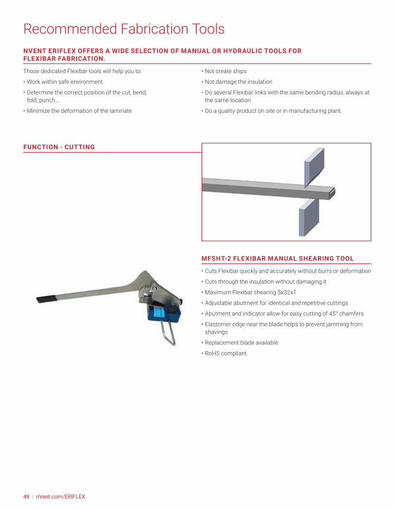
MFSHT-2 FLEXIBAR MANUAL SHEARING TOOL
• Cuts Flexibar quickly and accurately without burrs or deformation
• Cuts through the insulation without damaging it
• Maximum Flexibar shearing 5x32x1
• Adjustable abutment for identical and repetitive cuttings
• Abutment and indicator allow for easy cutting of 45° chamfers
• Elastomer edge near the blade helps to prevent jamming from shavings
• Replacement blade available
• RoHS compliant.
48 | nVent.com/ERIFLEX
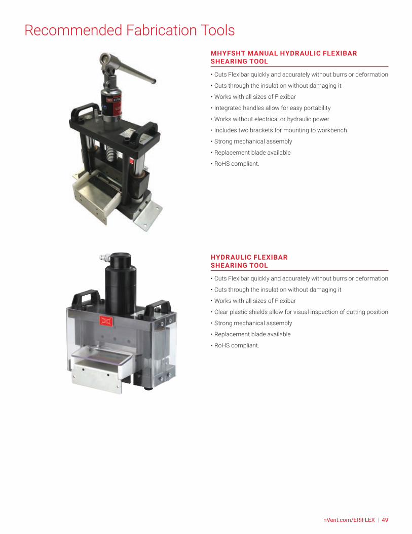
Recommended Fabrication ToolsMHYFSHT MANUAL HYDRAULIC FLEXIBAR SHEARING TOOL
• Cuts Flexibar quickly and accurately without burrs or deformation
• Cuts through the insulation without damaging it
• Works with all sizes of Flexibar
• Integrated handles allow for easy portability
• Works without electrical or hydraulic power
• Includes two brackets for mounting to workbench
• Strong mechanical assembly
• Replacement blade available
• RoHS compliant.
HYDRAULIC FLEXIBAR SHEARING TOOL
• Cuts Flexibar quickly and accurately without burrs or deformation
• Cuts through the insulation without damaging it
• Works with all sizes of Flexibar
• Clear plastic shields allow for visual inspection of cutting position
• Strong mechanical assembly
• Replacement blade available
• RoHS compliant.
nVent.com/ERIFLEX | 49
Recommended Fabrication ToolsFUNCTION - BENDING
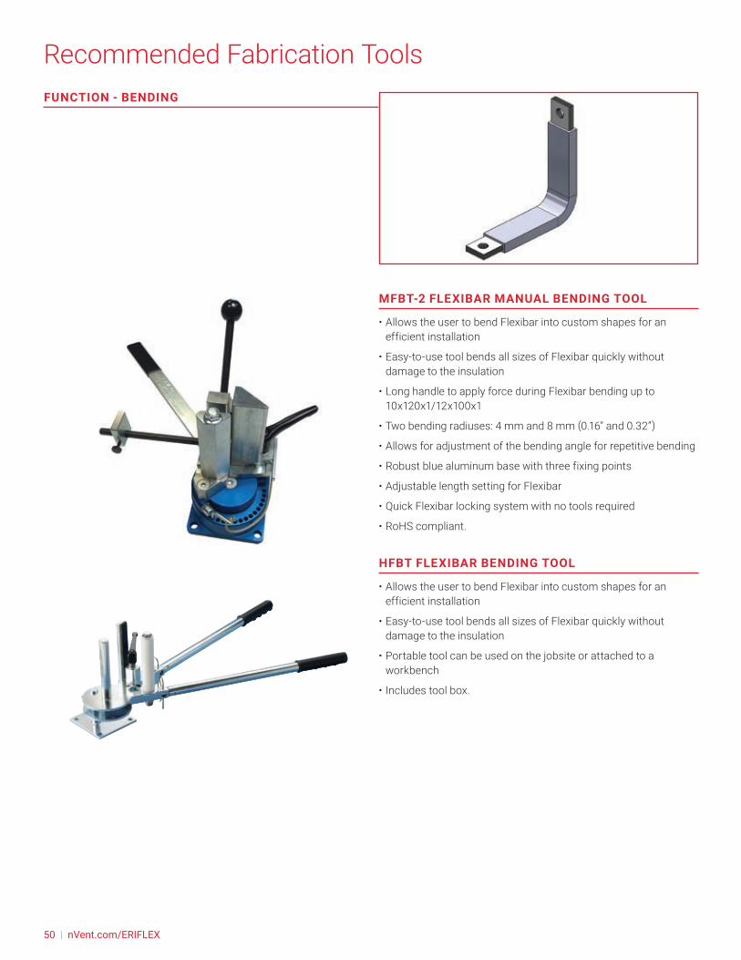
MFBT-2 FLEXIBAR MANUAL BENDING TOOL
• Allows the user to bend Flexibar into custom shapes for an efficient installation
• Easy-to-use tool bends all sizes of Flexibar quickly without damage to the insulation
• Long handle to apply force during Flexibar bending up to 10x120x1/12x100x1
• Two bending radiuses: 4 mm and 8 mm (0.16” and 0.32”)
• Allows for adjustment of the bending angle for repetitive bending
• Robust blue aluminum base with three fixing points
• Adjustable length setting for Flexibar
• Quick Flexibar locking system with no tools required
• RoHS compliant.
HFBT FLEXIBAR BENDING TOOL
• Allows the user to bend Flexibar into custom shapes for an efficient installation
• Easy-to-use tool bends all sizes of Flexibar quickly without damage to the insulation
• Portable tool can be used on the jobsite or attached to a workbench
• Includes tool box.
50 | nVent.com/ERIFLEX

Recommended Fabrication Tools
FUNCTION - TWISTING
MFTT-2 FLEXIBAR MANUAL TWISTING TOOL
• Easy-to-use tool twists or changes the plane of Flexibar
• Recommended to hold Flexibar while forming
• RoHS compliant.
HYDRAULIC FLEXIBLE/NON-FLEXIBLE BUSBAR BENDER
• Works with copper or aluminium busbar and Flexibar
• Multi-function tool creates “V” or “Z” bends and straightens busbar for corrections
• Removable top plate allows for multiple bends on a busbar
• Bottom plate is etched to indicate a 90° bend
• Includes steel bar supports for bending busbar when tool is not fixed to the Hydraulic Flexibar and Busbar Work Center
• RoHS compliant.
nVent.com/ERIFLEX | 51
Recommended Fabrication ToolsFUNCTION - FOLDING
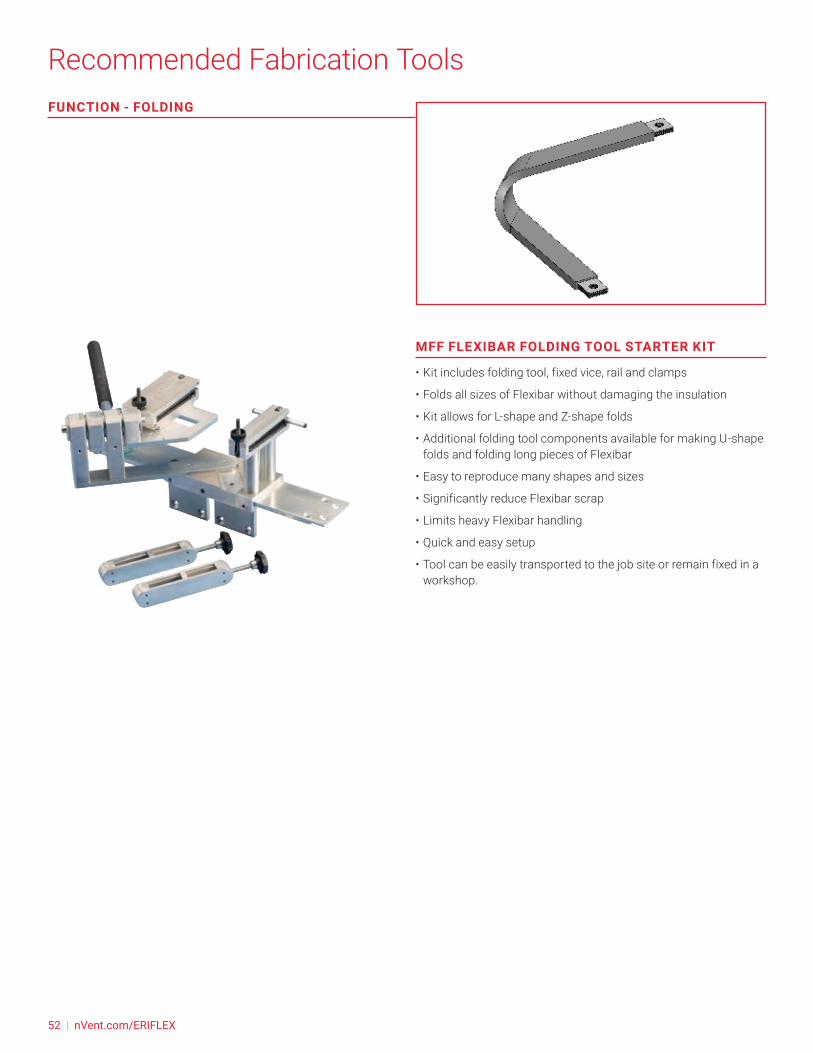
MFF FLEXIBAR FOLDING TOOL STARTER KIT
• Kit includes folding tool, fixed vice, rail and clamps
• Folds all sizes of Flexibar without damaging the insulation
• Kit allows for L-shape and Z-shape folds
• Additional folding tool components available for making U-shape folds and folding long pieces of Flexibar
• Easy to reproduce many shapes and sizes
• Significantly reduce Flexibar scrap
• Limits heavy Flexibar handling
• Quick and easy setup
• Tool can be easily transported to the job site or remain fixed in a workshop.
52 | nVent.com/ERIFLEX
Recommended Fabrication Tools
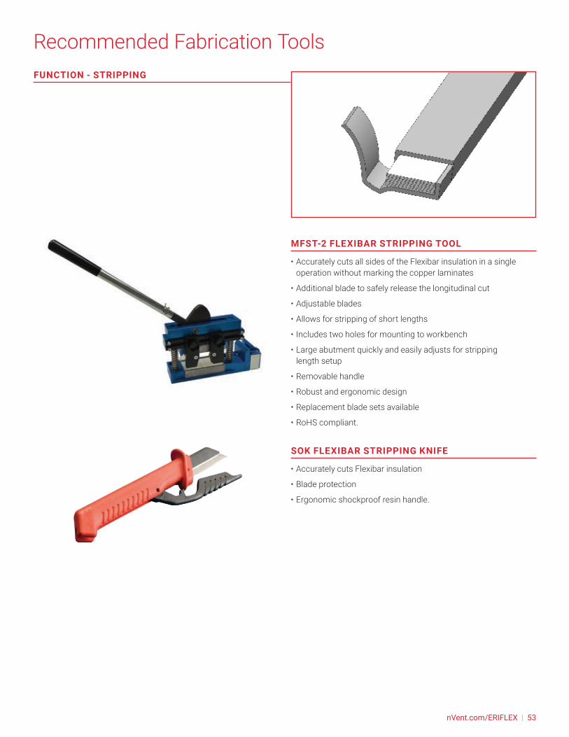
MFST-2 FLEXIBAR STRIPPING TOOL
• Accurately cuts all sides of the Flexibar insulation in a single operation without marking the copper laminates
• Additional blade to safely release the longitudinal cut
• Adjustable blades
• Allows for stripping of short lengths
• Includes two holes for mounting to workbench
• Large abutment quickly and easily adjusts for stripping length setup
• Removable handle
• Robust and ergonomic design
• Replacement blade sets available
• RoHS compliant.
SOK FLEXIBAR STRIPPING KNIFE
• Accurately cuts Flexibar insulation
• Blade protection
• Ergonomic shockproof resin handle.
FUNCTION - STRIPPING
nVent.com/ERIFLEX | 53

Recommended Fabrication ToolsFUNCTION - PUNCHING
MFPT FLEXIBAR PUNCHING TOOL
• Works with copper or aluminum busbar and Flexibar up to 6 mm thickness
• Punches flat and clean hole edges
• Quick and easy installation and setup
• Accurately punch Flexibar in a single operation without marking the copper laminates
• Quick setup with interchangeable punch and die system
• Large range of round punches and dies available
• Robust blue steel base with four fixing points
• Adjustable length setting for Flexibar, up to 90mm
• Removable handle
• Portable tool can be used on the jobsite or attached to a workbench
• RoHS compliant.
HYDRAULIC FLEXIBLE/NON-FLEXIBLE BUSBAR PUNCHER
• Works with copper or aluminium busbar and Flexibar
• Punches flat and clean hole edges
• Punch pip to adjust the hole position
• Quick setup with interchangeable punch and die system
• Large range of round and oval punches and dies available
• Can be tilted at a 45° angle for easier punching of formed busbar
• Calibrated side and depth gauge and stop
• Strong mechanical assembly
• RoHS compliant.
54 | nVent.com/ERIFLEX

Recommended Fabrication Tools
FLEXIDRILL DRILL GUIDE
• Guide for drilling holes into Flexibar, PBC Braided Power Shunts and PPS Presswelded Power Shunts
• Includes dies for mutiple diameters
• Adjustable guides allow for multiple hole center to hole center distances
• RoHS compliant.
FUNCTION - DRILLING
See our web site, nVent.com/ERIFLEX for full products data’s and video’sTools video’s also available from our nVent ERIFLEX YouTube channel.Those tools been developed for nVent ERIFLEX Flexibar only. Other Flexible busbar brand may not resist to some radius provided by those tools.
nVent.com/ERIFLEX | 55

Made to Order Solutions (MTO)FLEXIBAR CUSTOM SOLUTIONS (MADE TO ORDER)
nVent ERIFLEX can provide preformed Flexibar configurations to your drawing specifications. Flexibar can be cut, punched, twisted or bent to address your most challenging panelboard designs and production scheduling requirements. Give nVent ERIFLEX your low voltage connection challenges!
56 | nVent.com/ERIFLEX

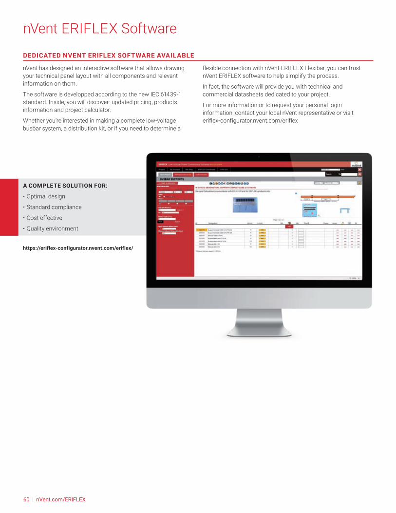
DEDICATED NVENT ERIFLEX SOFTWARE AVAILABLE
nVent has designed an interactive software that allows drawing your technical panel layout with all components and relevant information on them.
The software is developped according to the new IEC 61439-1 standard. Inside, you will discover: updated pricing, products information and project calculator.
Whether you’re interested in making a complete low-voltage busbar system, a distribution kit, or if you need to determine a
flexible connection with nVent ERIFLEX Flexibar, you can trust nVent ERIFLEX software to help simplify the process.
In fact, the software will provide you with technical and commercial datasheets dedicated to your project.
For more information or to request your personal login information, contact your local nVent representative or visit eriflex-configurator.nvent.com/eriflex
https://eriflex-configurator.nvent.com/eriflex/
nVent ERIFLEX Software
A COMPLETE SOLUTION FOR:
• Optimal design
• Standard compliance
• Cost effective
• Quality environment
60 | nVent.com/ERIFLEX
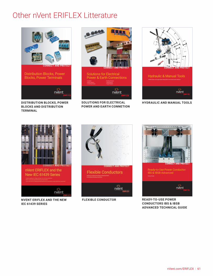
DISTRIBUTION BLOCKS, POWER BLOCKS AND DISTRIBUTION TERMINAL
HYDRAULIC AND MANUAL TOOLSSOLUTIONS FOR ELECTRICAL POWER AND EARTH CONNETION
FLEXIBLE CONDUCTOR READY-TO-USE POWER CONDUCTORS IBS & IBSB ADVANCED TECHNICAL GUIDE
NVENT ERIFLEX AND THE NEW IEC 61439 SERIES
Distribution Blocks, Power Blocks, Power Terminals Hydraulic & Manual Tools
Flexible Busbar and Copper Busbar Manipulation and Transformation Solutions
Solutions for Electrical Power & Earth Connections• Insulators• Busbar Supports• Connecting Clamps
• Earthing Products• Cabling Sleeves• Copper Busbars
Ready-to-Use Power Conductor:IBS & IBSB AdvancedTechnical Guide
Other nVent ERIFLEX Litterature
nVent.com/ERIFLEX | 61


nVent.com/ERIFLEX
©2019 nVent. All nVent marks and logos are owned or licensed by nVent Services GmbH or its affiliates. All other trademarks are the property of their respective owners. nVent reserves the right to change specifications without notice.
ERIFLEX-TH-P1349W-FlexiBar-USEN-1904
CADDY ERICO HOFFMAN RAYCHEM SCHROFF TRACEROur powerful portfolio of brands: