nwrl viaduct construction span 60 failure … viaduct construction span 60 failure assessment...
TRANSCRIPT

NWRL Viaduct Construction
Span 60 Failure Assessment
Transport for NSW
23 November 2016
Revision: Final
Reference: 254312
Document control record
Document prepared by:
Aurecon Australasia Pty Ltd ABN 54 005 139 873
Level 5, 116 Military Road Neutral Bay NSW 2089
PO Box 538 Neutral Bay NSW 2089 Australia
T F E W
+61 2 9465 5599 +61 2 9465 5598 [email protected] aurecongroup.com
A person using Aurecon documents or data accepts the risk of:
a) Using the documents or data in electronic form without requesting and checking them for accuracy against the original hard copy version.
b) Using the documents or data for any purpose not agreed to in writing by Aurecon.
NWRL Viaduct Construction
Date 23 November 2016
Reference 254312 Revision Final
Aurecon Australasia Pty Ltd ABN 54 005 139 873
Level 5, 116 Military Road Neutral Bay NSW 2089
PO Box 538 Neutral Bay NSW 2089 Australia
T F E W
+61 2 9465 5599 +61 2 9465 5598 [email protected] aurecongroup.com
i
Contents 1 Introduction 1
1.1 General 1
1.2 Span 60 2
2 Relevant project documents 3
3 Concrete segment strength at transfer 5
4 Closure pour 8
4.1 First grout placement 9
4.2 Second grout placement 10
5 Epoxy injection 12
6 Stitch cross section properties 13
7 Strain gauges 16
8 Construction quality control 18
9 Causes of failure 19
10 Current stability of box girder 20
11 Recommendations 22
Appendix A Dismantling Procedure
Page 1
1.1 General
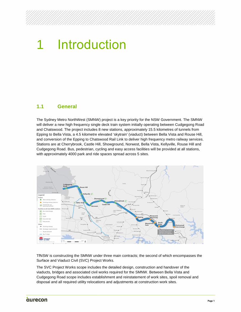
The Sydney Metro NorthWest (SMNW) project is a key priority for the NSW Government. The SMNW will deliver a new high frequency single deck train system initially operating between Cudgegong Road and Chatswood. The project includes 8 new stations, approximately 15.5 kilometres of tunnels from Epping to Bella Vista, a 4.5 kilometre elevated ‘skytrain’ (viaduct) between Bella Vista and Rouse Hill, and conversion of the Epping to Chatswood Rail Link to deliver high frequency metro railway services. Stations are at Cherrybrook, Castle Hill, Showground, Norwest, Bella Vista, Kellyville, Rouse Hill and Cudgegong Road. Bus, pedestrian, cycling and easy access facilities will be provided at all stations, with approximately 4000 park and ride spaces spread across 5 sites.
TfNSW is constructing the SMNW under three main contracts; the second of which encompasses the Surface and Viaduct Civil (SVC) Project Works.
The SVC Project Works scope includes the detailed design, construction and handover of the viaducts, bridges and associated civil works required for the SMNW. Between Bella Vista and Cudgegong Road scope includes establishment and reinstatement of work sites, spoil removal and disposal and all required utility relocations and adjustments at construction work sites.
1 Introduction
Page 2
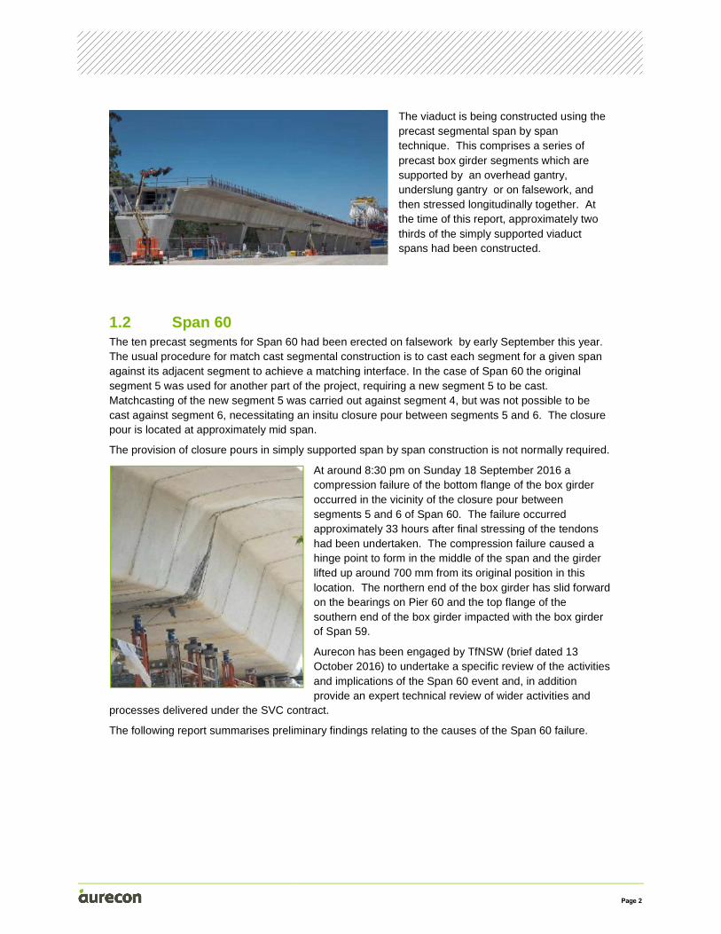
The viaduct is being constructed using the precast segmental span by span technique. This comprises a series of precast box girder segments which are supported by an overhead gantry, underslung gantry or on falsework, and then stressed longitudinally together. At the time of this report, approximately two thirds of the simply supported viaduct spans had been constructed.
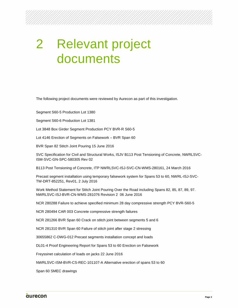
1.2 Span 60 The ten precast segments for Span 60 had been erected on falsework by early September this year. The usual procedure for match cast segmental construction is to cast each segment for a given span against its adjacent segment to achieve a matching interface. In the case of Span 60 the original segment 5 was used for another part of the project, requiring a new segment 5 to be cast. Matchcasting of the new segment 5 was carried out against segment 4, but was not possible to be cast against segment 6, necessitating an insitu closure pour between segments 5 and 6. The closure pour is located at approximately mid span.
The provision of closure pours in simply supported span by span construction is not normally required.
At around 8:30 pm on Sunday 18 September 2016 a compression failure of the bottom flange of the box girder occurred in the vicinity of the closure pour between segments 5 and 6 of Span 60. The failure occurred approximately 33 hours after final stressing of the tendons had been undertaken. The compression failure caused a hinge point to form in the middle of the span and the girder lifted up around 700 mm from its original position in this location. The northern end of the box girder has slid forward on the bearings on Pier 60 and the top flange of the southern end of the box girder impacted with the box girder of Span 59.
Aurecon has been engaged by TfNSW (brief dated 13 October 2016) to undertake a specific review of the activities and implications of the Span 60 event and, in addition provide an expert technical review of wider activities and
processes delivered under the SVC contract.
The following report summarises preliminary findings relating to the causes of the Span 60 failure.
Page 3
The following project documents were reviewed by Aurecon as part of this investigation.
Segment S60-5 Production Lot 1380
Segment S60-6 Production Lot 1381
Lot 3848 Box Girder Segment Production PCY BVR-R S60-5
Lot 4146 Erection of Segments on Falsework – BVR Span 60
BVR Span 82 Stitch Joint Pouring 15 June 2016
SVC Specification for Civil and Structural Works, ISJV B113 Post Tensioning of Concrete, NWRLSVC-ISM-SVC-GN-SPC-580305 Rev 02
B113 Post Tensioning of Concrete, ITP NWRLSVC-ISJ-SVC-CN-WMS-280161, 24 March 2016
Precast segment installation using temporary falsework system for Spans 53 to 60, NWRL-ISJ-SVC-TW-DRT-852251, Rev01, 2 July 2016
Work Method Statement for Stitch Joint Pouring Over the Road including Spans 82, 85, 87, 89, 97. NWRLSVC-ISJ-BVR-CN-WMS-281076 Revision 2 06 June 2016
NCR 280288 Failure to achieve specified minimum 28 day compressive strength PCY BVR-S60-5
NCR 280494 CAR 003 Concrete compressive strength failures
NCR 281266 BVR Span 60 Crack on stitch joint between segments 5 and 6
NCR 281310 BVR Span 60 Failure of stitch joint after stage 2 stressing
30655862 C-DWG-012 Precast segments installation concept and loads
DL01-4 Proof Engineering Report for Spans 53 to 60 Erection on Falsework
Freyssinet calculation of loads on jacks 22 June 2016
NWRLSVC-ISM-BVR-CS-REC-101107-A Alternative erection of spans 53 to 60
Span 60 SMEC drawings
2 Relevant project documents
Page 4
DL27 – Concrete mix designs for pile, pile cap, pier and precast segments 29 January 2016
SVC specification for civil and structural works Rev 02
TfNSW – Spalling at Span 60 on 18 September 2016 – History of Events
TfNSW Briefing 27 September 2016
NWRLSVC-ISJ-SVC-CS-DRT-270100.AFC-2
NWRLSVC-ISJ-SVC-CN-REG-180580 R.01 Segment Test Results
Concrete test results CON GRA15 13672-56D
Grout material test results (Coffey, Hanson)
SMEC Memo 12 October 2016: BVR Span 60 details
TDS TamRez 210
SMEC Construction sequence
TDS BluCem H80 early strength grout
BS EN 206-2013 Concrete
AS 5100 2004 Australian Bridge Design Standard
Strain gauge monitoring results for Span 60
Hazard Identification Worksheet for Span 60
Hazard Identification for Span 60 Briefing Note
Page 5
For match cast segmental box girder superstructures built span by span the compressive stress in the bottom flange is at a highest level immediately after prestressing is complete. This condition is referred to as transfer.
For Span 60 Aurecon has calculated the design compression stress in the bottom flange immediately after transfer to be 33 MPa, assuming the design and layout as shown on Drawing NWRLSVC-ISM-BVR-CS-DRG-015200. (Note: This assumes both adequate strength and uniform properties across the interface of segments 5 and 6. There is strong evidence that neither of these items has been achieved. This is discussed further in this report.)
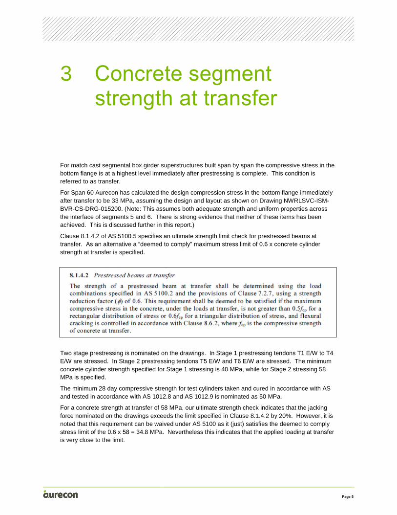
Clause 8.1.4.2 of AS 5100.5 specifies an ultimate strength limit check for prestressed beams at transfer. As an alternative a “deemed to comply” maximum stress limit of 0.6 x concrete cylinder strength at transfer is specified.
Two stage prestressing is nominated on the drawings. In Stage 1 prestressing tendons T1 E/W to T4 E/W are stressed. In Stage 2 prestressing tendons T5 E/W and T6 E/W are stressed. The minimum concrete cylinder strength specified for Stage 1 stressing is 40 MPa, while for Stage 2 stressing 58 MPa is specified.
The minimum 28 day compressive strength for test cylinders taken and cured in accordance with AS and tested in accordance with AS 1012.8 and AS 1012.9 is nominated as 50 MPa.
For a concrete strength at transfer of 58 MPa, our ultimate strength check indicates that the jacking force nominated on the drawings exceeds the limit specified in Clause 8.1.4.2 by 20%. However, it is noted that this requirement can be waived under AS 5100 as it (just) satisfies the deemed to comply stress limit of the 0.6 x 58 = 34.8 MPa. Nevertheless this indicates that the applied loading at transfer is very close to the limit.
3 Concrete segment strength at transfer
Page 6
Clause 8.1.4.2 specifies that if the stress block has a rectangular distribution the stress should be limited to 0.5fcp and if the stress block has a triangular distribution the stress should be limited to 0.6fcp. Over the depth of the Span 60 box girder the stress block would not be triangular.
A review of compressive stress limits in various international bridge codes has been undertaken as part of this investigation. The 0.6 fcp stress limit at transfer is specified in AASHTO LRFD Bridge Design Code, AASHTO Guide Specification for the Design and Construction of Segmental Concrete Bridges 2003 Interim, BSEN1992-1.1 and the Canadian Bridge Design Code CAN/CSA-S6-06, without the lower limit for a rectangular stress block.
It is therefore considered that the 0.5fcp limit for the bottom flange is not applicable.
The trial concrete mix strength results indicate a 28 day compressive strength of 73.7 MPa. The trial concrete mix appears to fully comply with the requirements of Specification B80.
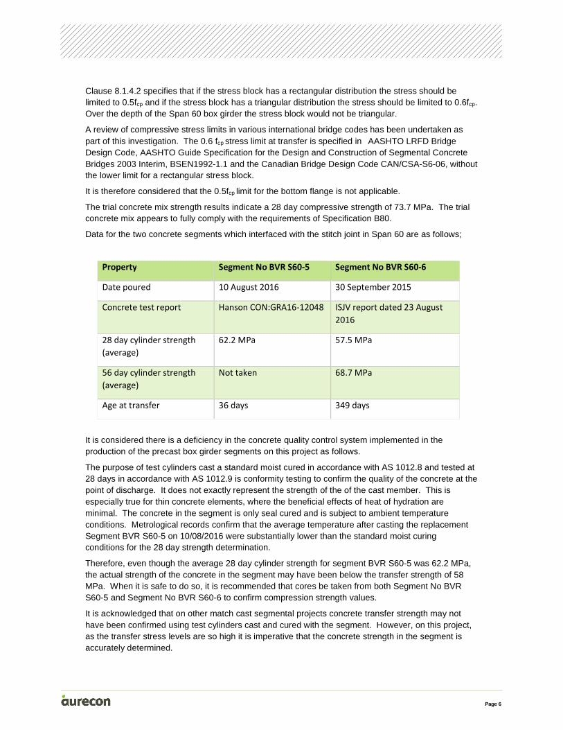
Data for the two concrete segments which interfaced with the stitch joint in Span 60 are as follows;
Property Segment No BVR S60-5 Segment No BVR S60-6
Date poured 10 August 2016 30 September 2015
Concrete test report Hanson CON:GRA16-12048 ISJV report dated 23 August
2016
28 day cylinder strength
(average)
62.2 MPa 57.5 MPa
56 day cylinder strength
(average)
Not taken 68.7 MPa
Age at transfer 36 days 349 days
It is considered there is a deficiency in the concrete quality control system implemented in the production of the precast box girder segments on this project as follows.
The purpose of test cylinders cast a standard moist cured in accordance with AS 1012.8 and tested at 28 days in accordance with AS 1012.9 is conformity testing to confirm the quality of the concrete at the point of discharge. It does not exactly represent the strength of the of the cast member. This is especially true for thin concrete elements, where the beneficial effects of heat of hydration are minimal. The concrete in the segment is only seal cured and is subject to ambient temperature conditions. Metrological records confirm that the average temperature after casting the replacement Segment BVR S60-5 on 10/08/2016 were substantially lower than the standard moist curing conditions for the 28 day strength determination.
Therefore, even though the average 28 day cylinder strength for segment BVR S60-5 was 62.2 MPa, the actual strength of the concrete in the segment may have been below the transfer strength of 58 MPa. When it is safe to do so, it is recommended that cores be taken from both Segment No BVR S60-5 and Segment No BVR S60-6 to confirm compression strength values.
It is acknowledged that on other match cast segmental projects concrete transfer strength may not have been confirmed using test cylinders cast and cured with the segment. However, on this project, as the transfer stress levels are so high it is imperative that the concrete strength in the segment is accurately determined.
Page 7
More generally across the project, we understand that while 28 day strength results for the standard moist cured cylinders have been satisfactory, there have been low results, which have been attributed to variations in the quality of the fly ash the re-cycled mixing water used in the manufacture of the production concrete or possibly other causes. Test results have been lower than the compressive strength of the trial mix. It is not clear if the source of the re-cycled water used for the trial mix is the same as that used for the production of concrete.
Specifying a concrete transfer strength higher than the 28 day compressive strength is unorthodox. Aurecon are unaware of any other project where the transfer strength has been taken higher than the nominated 28 day compressive strength. For this approach the actual strength of the concrete in the segment needs to be accurately determined. Using standard moist cured cylinders for this purpose is not considered appropriate.
Page 8
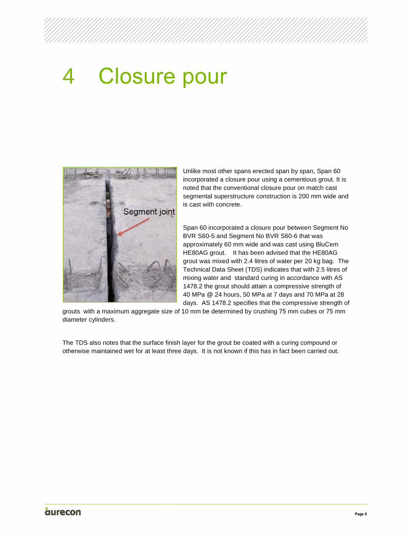
Unlike most other spans erected span by span, Span 60 incorporated a closure pour using a cementious grout. It is noted that the conventional closure pour on match cast segmental superstructure construction is 200 mm wide and is cast with concrete.
Span 60 incorporated a closure pour between Segment No BVR S60-5 and Segment No BVR S60-6 that was approximately 60 mm wide and was cast using BluCem HE80AG grout. It has been advised that the HE80AG grout was mixed with 2.4 litres of water per 20 kg bag. The Technical Data Sheet (TDS) indicates that with 2.5 litres of mixing water and standard curing in accordance with AS 1478.2 the grout should attain a compressive strength of 40 MPa @ 24 hours, 50 MPa at 7 days and 70 MPa at 28 days. AS 1478.2 specifies that the compressive strength of
grouts with a maximum aggregate size of 10 mm be determined by crushing 75 mm cubes or 75 mm diameter cylinders.
The TDS also notes that the surface finish layer for the grout be coated with a curing compound or otherwise maintained wet for at least three days. It is not known if this has in fact been carried out.
4 Closure pour
Page 9
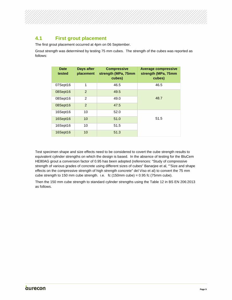
4.1 First grout placement The first grout placement occurred at 4pm on 06 September.
Grout strength was determined by testing 75 mm cubes. The strength of the cubes was reported as follows:
Date tested
Days after placement
Compressive strength (MPa, 75mm
cubes)
Average compressive strength (MPa, 75mm
cubes)
07Sept16 1 46.5 46.5
08Sept16 2 49.5
48.7 08Sept16 2 49.0
08Sept16 2 47.5
16Sept16 10 52.0
51.5 16Sept16 10 51.0
16Sept16 10 51.5
16Sept16 10 51.3
Test specimen shape and size effects need to be considered to covert the cube strength results to equivalent cylinder strengths on which the design is based. In the absence of testing for the BluCem HE80AG grout a conversion factor of 0.95 has been adopted (references: “Study of compressive strength of various grades of concrete using different sizes of cubes” Banarjee et al, “”Size and shape effects on the compressive strength of high strength concrete” del Viso et al) to convert the 75 mm cube strength to 150 mm cube strength. i.e. fc (150mm cube) = 0.95 fc (75mm cube).
Then the 150 mm cube strength to standard cylinder strengths using the Table 12 in BS EN 206:2013 as follows.
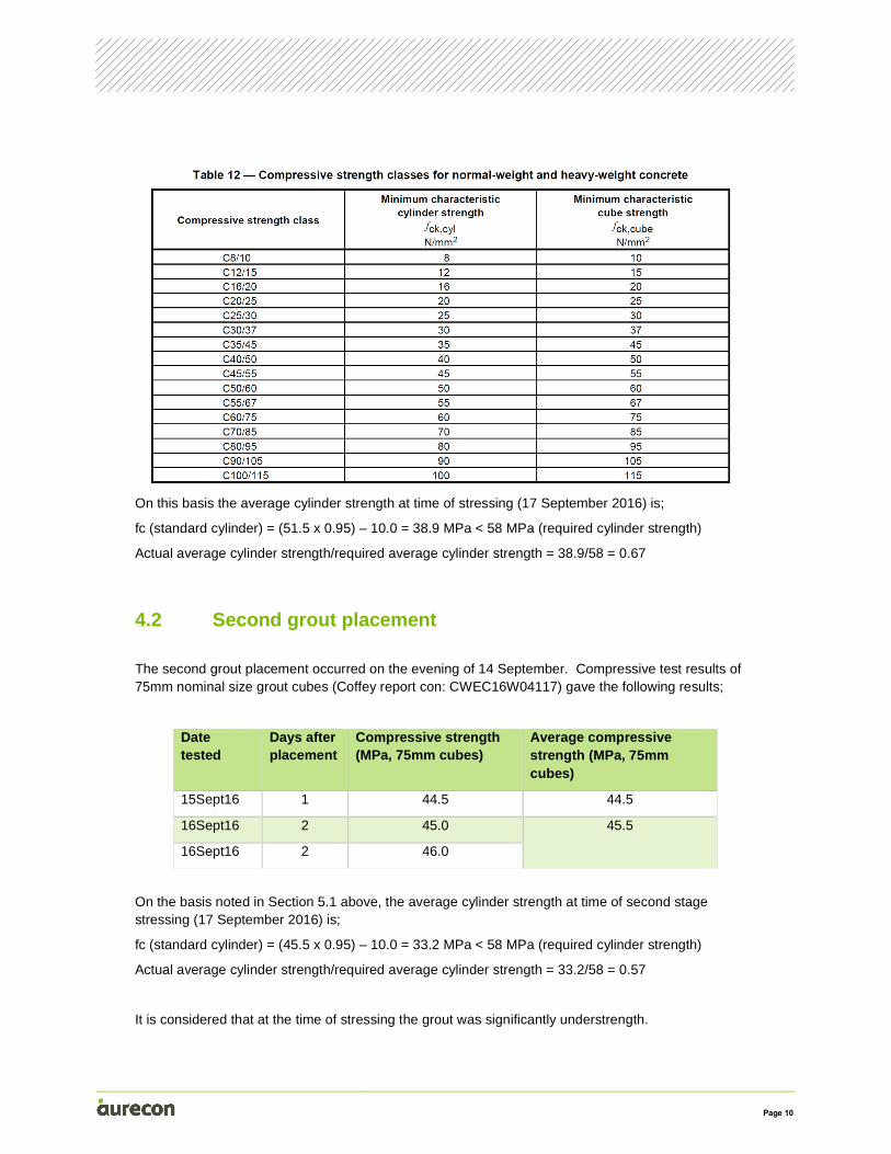
Page 10
On this basis the average cylinder strength at time of stressing (17 September 2016) is;
fc (standard cylinder) = (51.5 x 0.95) – 10.0 = 38.9 MPa < 58 MPa (required cylinder strength)
Actual average cylinder strength/required average cylinder strength = 38.9/58 = 0.67
4.2 Second grout placement
The second grout placement occurred on the evening of 14 September. Compressive test results of 75mm nominal size grout cubes (Coffey report con: CWEC16W04117) gave the following results;
Date tested
Days after placement
Compressive strength (MPa, 75mm cubes)
Average compressive strength (MPa, 75mm cubes)
15Sept16 1 44.5 44.5
16Sept16 2 45.0 45.5
16Sept16 2 46.0
On the basis noted in Section 5.1 above, the average cylinder strength at time of second stage stressing (17 September 2016) is;
fc (standard cylinder) = (45.5 x 0.95) – 10.0 = 33.2 MPa < 58 MPa (required cylinder strength)
Actual average cylinder strength/required average cylinder strength = 33.2/58 = 0.57
It is considered that at the time of stressing the grout was significantly understrength.

Page 11
It is recommended that standard cylinders should be tested to confirm grout strengths, rather than cubes. Alternatively tests be undertaken to enable the factor for 75 mm cube strengths of the grout to be accurately converted to the equivalent concrete cylinder strength.
Page 12
In general, epoxy injection of grouted stitch joints in precast segmental construction, which will subsequently carry load, is not recommended due to impracticalities in ensuring an even bearing surface across the full face of the joint.
In this instance the joint was epoxy injected. The epoxy used for the injection was “Tamrez 210” extra low viscosity injection resin.
The product TDS shows this material has a compressive strength of 82.2 MPa, a Modulus of Elasticity of 1100 MPa at a final cure of 7 days.
With injection on 12 September 2016, the material had an actual curing time of only 3 days with stage 1 stressing on 15 September 2016.
Assuming an equivalent cylinder strength of the grout of 38.9 MPa, and a density of 2300 kg/m3 gives a mean modulus of elasticity of 29600 MPa, so the epoxy has less than 4% of the stiffness of the grout.
For equal thicknesses, the epoxy will take only 4% of the applied load initially, and this will actually be less due to hysteresis effects of loading the epoxy, and subsequent creep of the epoxy.
5 Epoxy injection
Page 13
In order to estimate the stiffness properties across the joint we need to revisit the sequence of construction.
Time Date Activity Implications
4pm 06 Sept Grout placement #1 over full cross section
07 Sept Cracks observed 0.3-0.6mm through the whole cross section
Due to thermal contraction and absence of tensioned steel ties across the joint
09 Sept Temporary restraint applied to top flange (2) and bottom flange (1) and tightened manually with the intention to stop the closure pour from closing.
No restraint provided to stop the closure pour from opening.
Epoxy paste applied around the external face and internal face of segment as preparation for epoxy injection
Cracks remeasured and found to be up to 1.3mm
Due to thermal contraction and absence of tensioned steel ties across the joint
10 Sept Cracks identified through the paste on both cantilevers. This is due to movement across the joint, after the epoxy paste was applied.
It is understood that these cracks were less than 0.2mm.
Due to thermal contraction and absence of tensioned steel ties across the joint
6 Stitch cross section properties
Page 14
12 Sept Epoxy injection occurred to the whole cross section with the exception of the cantilevers.
It is understood (from Mehdi Afshar) that the injection was unsuccessful to the top flange as the epoxy was running away into the unsealed cantilevers.
In the evening temporary restraints altered to stop the joints from opening. It is understood that these restraints were tightened manually
By simple calculation, manual tightening of the ties may not stop the joint opening sufficiently to stop the joint from cracking.
13 Sept The epoxy repaired crack in the top flange was observed to have reopened to 3-4mm in the top flange, but not at the cantilevers.
Evidence of lack of effectiveness of the temporary restraints.
14 Sept Grout placement #2 over central 8m of top flange following removal of the grout and epoxy in the flange
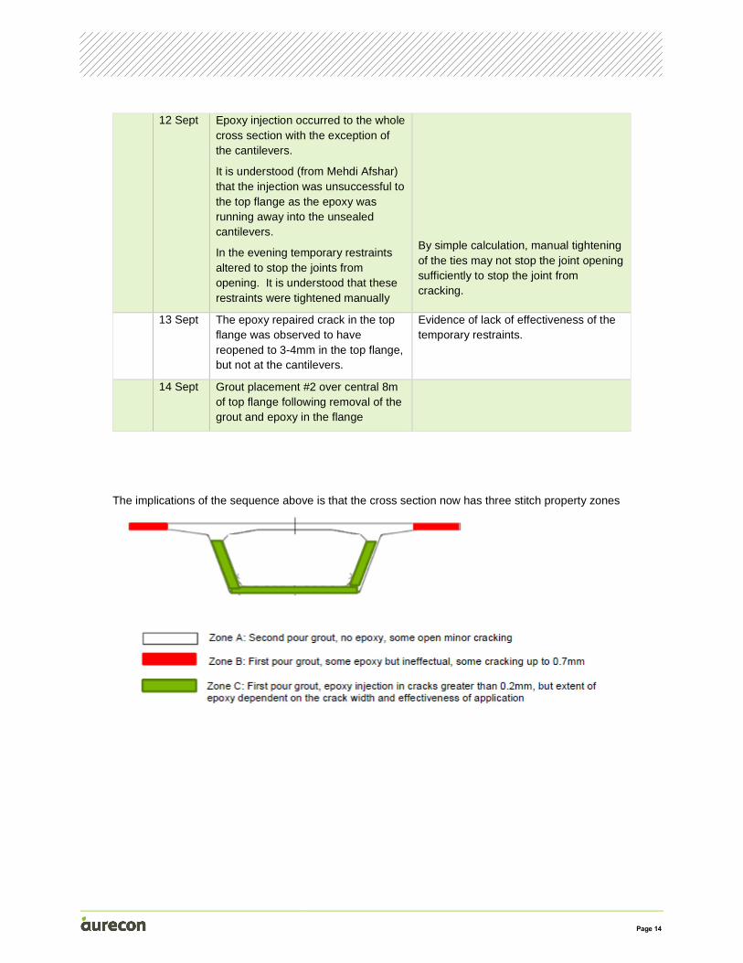
The implications of the sequence above is that the cross section now has three stitch property zones
Page 15
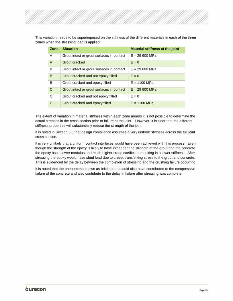
This variation needs to be superimposed on the stiffness of the different materials in each of the three zones when the stressing load is applied.
Zone Situation Material stiffness at the joint
A Grout intact or grout surfaces in contact E = 29 600 MPa
A Grout cracked E = 0
B Grout intact or grout surfaces in contact E = 29 600 MPa
B Grout cracked and not epoxy filled E = 0
B Grout cracked and epoxy filled E = 1100 MPa
C Grout intact or grout surfaces in contact E = 29 600 MPa
C Grout cracked and not epoxy filled E = 0
C Grout cracked and epoxy filled E = 1100 MPa
The extent of variation in material stiffness within each zone means it is not possible to determine the actual stresses in the cross section prior to failure at the joint. However, it is clear that the different stiffness properties will substantially reduce the strength of the joint.
It is noted in Section 3.0 that design compliance assumes a very uniform stiffness across the full joint cross section.
It is very unlikely that a uniform contact interfaces would have been achieved with this process. Even though the strength of the epoxy is likely to have exceeded the strength of the grout and the concrete the epoxy has a lower modulus and much higher creep coefficient resulting in a lower stiffness. After stressing the epoxy would have shed load due to creep, transferring stress to the grout and concrete. This is evidenced by the delay between the completion of stressing and the crushing failure occurring.
It is noted that the phenomena known as brittle creep could also have contributed to the compressive failure of the concrete and also contribute to the delay in failure after stressing was complete.
Page 16
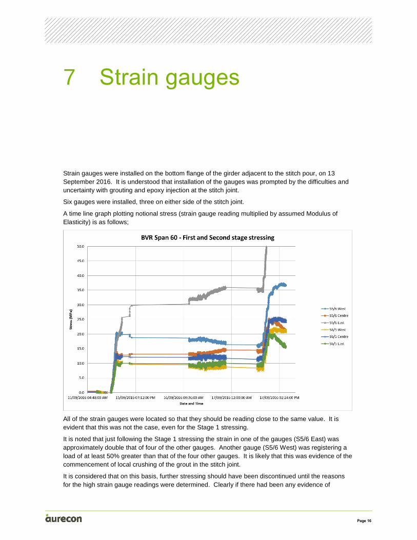
Strain gauges were installed on the bottom flange of the girder adjacent to the stitch pour, on 13 September 2016. It is understood that installation of the gauges was prompted by the difficulties and uncertainty with grouting and epoxy injection at the stitch joint.
Six gauges were installed, three on either side of the stitch joint.
A time line graph plotting notional stress (strain gauge reading multiplied by assumed Modulus of Elasticity) is as follows;
All of the strain gauges were located so that they should be reading close to the same value. It is evident that this was not the case, even for the Stage 1 stressing.
It is noted that just following the Stage 1 stressing the strain in one of the gauges (S5/6 East) was approximately double that of four of the other gauges. Another gauge (S5/6 West) was registering a load of at least 50% greater than that of the four other gauges. It is likely that this was evidence of the commencement of local crushing of the grout in the stitch joint.
It is considered that on this basis, further stressing should have been discontinued until the reasons for the high strain gauge readings were determined. Clearly if there had been any evidence of
7 Strain gauges
Page 17
distress of the grout or concrete, alleviating measures, such as destressing some or all of the tendons should have been undertaken.
Following the Stage 2 stressing, the strain in gauges S5/6 East and S5/6 West continued to rise, and failure occurred sometime thereafter.

Page 18
For the casting of segments BVR-S60-5&6 verification check lists incorporating hold and witness points have been completed and appear to be in order.
The Work Method Statement for BVR Span 60 Stitch Joint Pouring (NWRLSVC-ISJ-BVR-CN-WMS-280177 Revision 01 dated 31 August 2016) specifies the process of constructing the stitch pour.
Comments relating to this Work Method Statement (WMS) are as follows;
• The timing of the casting of the stitch pour was not specified
• There is no evidence that the grout was cured after installation as required by the WMS, Clause 5, item 3
• There is no evidence that the push-pull ties were installed prior to casting of the stitch pour as required by the WMS, Clause 5, item 2
• The note on figure 7 “Typical Stitch Joint” indicates the use of a 50 MPa non shrink grout. It is noted that this is below the required transfer strength of 58 MPa.
With reference to SVC Specification for Civil and Structural Works, ISJV B113 Post Tensioning of Concrete, NWRLSVC-ISM-SVC-GN-SPC-580305 Rev 02 and ITP NWRLSVC-ISJ-SVC-CN-WMS-280161 (B113 Post Tensioning of Concrete), 24 March 2016, there is no evidence of the release of the hold point for Clause 9.1.1 relating to the strength of the grout.
There are two Non Conformance Reports (NCR’s) which have been provided.
• NCR#281266 “Crack on stitch joint between segments 5 and 6” which does not appear to have been signed off.
• NCR#281310 “Failure of stitch joint after stage 2 stressing” which does not appear to have been signed off.
8 Construction quality control
Page 19
As noted in Section 3.0 the bottom flange at time of prestress transfer is under a condition of high theoretical compressive stress. In addition to being high, this stress is only marginally below the design stress limit noted in Clause 8.1.4.2 of AS 5100.5. In this circumstance, it is very important that actual as constructed member properties meet the designer’s intent.
On this basis, the following technical deficiencies are considered to have contributed to the span failure.
• The equivalent cylinder strength of the grout (33-39MPa) is significantly below the required transfer strength of 58 MPa. It is noted that we have assessed this using recognised conversion factors. It is recommended that a test program be undertaken to enable the factor for 75 mm cube strengths of the grout to be accurately converted to the equivalent concrete cylinder strength.
• The failure to achieve a crack free grouted joint by the lack of an effective tensioned steel push/pull arrangement throughout the grouting process.
• Repair of the cracks using an inappropriate epoxy injection process which introduced a large stiffness differential across the cross section.
• The decision to continue the stressing process and not to destress, when evidence from the strain gauge monitoring indicated significantly uneven strains.
• The concrete in Segment No BVR S60-5 may have not obtained the required transfer strength.
For new segments, it is recommended that cylinders cast and cured in the same manner as the segments be used for determining transfer strength.
For segments which have already been cast it is recommended that they not be prestressed until either the corresponding 28 day or 56 day standard moist cured cylinders have attained a strength of at least 60 MPa. Otherwise test cores should be taken from the segment to confirm the transfer strength has been achieved.
9 Causes of failure
Page 20
The Span 60 girder has moved upwards as a result of the localised crushing of the bottom flange and webs at the stitch pour producing a plastic hinge. The resultant structure became a mechanism, brought to equilibrium by a restoring couple formed by the longitudinally fixed bearings supporting the southern end of the Span 60 girder, and the top flange of the Span 59 girder bearing against the top flange of the Span 60 girder. In turn, the loading on the top flange of the Span 59 girder is being transferred to the longitudinally fixed bearing at its southern end.
The gross movement of the girder has also meant that the tendons through the central deviator have changed from upward slope change to downward slope change. All tendons are expected to be bearing on the top surface of the bottom slab at midspan. This will also act to provide a downwards force on the girder at midspan, assisting in preventing further upwards movement.
Based on an assessment of the current girder geometry in its lifted state the crushing of the bottom flange appears to have produced a shortening of the bottom flange length of a very approximate 150mm in a reasonably uniform manner across the width of the flange. The northern end of the Span 60 girder has moved forward on the longitudinally unrestrained bearings accordingly, and we understand this has been measured by survey to be approximately 230mm.
Our calculations indicate that the additional longitudinal load induced on the Span 59 and Span 60 bearings and piers due to the Span 60 failure is within the capacity of the bearings, and well within the capacity of the piers.
As a result of the shortening of the Span 60 bottom flange noted above, all of the prestressing tendons in the girder will have reduced in length by a similar amount. Aurecon has calculated the force in the tendons will have reduced to approximately 36% of the original force after the stage 2 jacking.
On this basis it is considered that the probability of the Span 60 girder in its current state failing catastrophically either by moving up, or down is considered low. However, this possibility needs to be allowed for in the dismantling procedure.
Due to the presence of a deviator located near midspan (in segment 6) there will have been some local bending in the tendons and the plastic sheaths in this location. Some damage to the tendon strands should not be ruled out.
All tendons in the Span 60 girder are unbonded. This means that in the unlikely event that a tendon strand fractured a large amount of energy would be released and could eject at high speed from the anchorage.
We therefore concur with the mitigation measures proposed in the recommendations in the Hazard Identification workshop that a timber ply bulkhead be provided close against the northern end face of the Span 60 girder, covering all the anchorages, and restrained in place. The proximity and strength of the end diaphragm of Span 59 is considered sufficient to protect persons from injury due to sudden strand release at the southern end of the Span 60 girder. However, consideration should be given to
10 Current stability of box girder
Page 21
providing a timber ply bulkhead in this location, to protect the anchorages on the northern end of the Span 59 girder.
Page 22
Recommendations for the rectification of Span 60 are as follows;
• To further evaluate the failure at Span 60, it is recommended that, when it is safe to do so, cores be taken from both Segment No BVR S60-5 and Segment No BVR S60-6 to confirm compression strength values.
• To further evaluate the failure at Span 60, it is recommended that tests be undertaken to enable the factor for 75 mm cube strengths of the grout to be accurately converted to the equivalent concrete cylinder strength.
• We concur with the mitigation measures proposed in the recommendations in the Hazard Identification workshop that a timber ply bulkhead be provided close against the northern end face of the Span 60 girder, covering all the anchorages, and restrained in place. The proximity and strength of the end diaphragm of Span 59 is considered sufficient to protect persons from injury due to sudden strand release at the southern end of the Span 60 girder. However, consideration should be given to providing a timber ply bulkhead in this location, to protect the anchorages on the northern end of the Span 59 girder.
Recommendations for future construction are as follows;
• Concrete cylinders used for determining the concrete strength at transfer should be cast and cured in the same manner as the member
• Standard cylinders should be tested to confim grout strengths rather than cubes. Alternatively, tests should be undertaken to enable the factor for 75 mm cube strengths of the grout to be accurately converted to the equivalent concrete cylinder strength.
• Grout should be cured in accordance with the manufacturer’s written instructions, eg the surface finish layer for the grout be coated with a curing compound or otherwise maintained wet for at least three days.
• Epoxy injection of grouted joints is not recommended due to impracticalities in ensuring an even bearing surface across the full face of the joint.
• The segments on either side of a closure pour should be securely clamped to ensure no movement across the closure pour until prestressing has commenced.
• Provide real time monitoring of strain gauges to enable extent and magnitude of stressing loads to be varied, depending on the results provided.
11 Recommendations
Appendix A Dismantling procedure
It is understood that Freyssinet are developing a dismantling procedure for Span 60.
It is recommended that the following needs to be taken into account in the development and execution of the dismantling procedure.
• Detensioning should proceed using a multi-strand jack with low spacer. This should be undertaken using two jacks and two crews so that the de-stressing is done symmetrically and from the outside anchorages in, so that towards the jacking operators do not need to walk behind tendons at current stress levels.
• It is generally recommended that Span 60 be lowered back onto supports at their original level. The top flange of the box girder appears to be intact. The de-tensioning should result in a gradual lowering of the box girder. The girder self weight produces a tensile stress of approximately 9.6 MPa in the bottom flange. If new falsework is installed at or just below the current soffit level of the box girder, there is a risk of further crushing. The net compressive stress in the bottom flange will increase by this amount (9.6 MPa) when the girder lands on the falsework.
• Brace falsework towers to ensure they remain stable when the box girder is lowered back onto them.

Aurecon Australasia Pty Ltd ABN 54 005 139 873
Level 5, 116 Military Road Neutral Bay NSW 2089 PO Box 538 Neutral Bay NSW 2089 Australia
T F E W
+61 2 9465 5599 +61 2 9465 5598 [email protected] aurecongroup.com
Aurecon offices are located in: Angola, Australia, Botswana, China, Ghana, Hong Kong, Indonesia, Kenya, Lesotho, Macau, Mozambique, Namibia, New Zealand, Nigeria, Philippines, Qatar, Singapore, South Africa, Swaziland, Tanzania, Thailand, Uganda, United Arab Emirates, Vietnam.