nwt assignment
TRANSCRIPT
Network Troubleshooting
NWT Page 1
Table of Contents
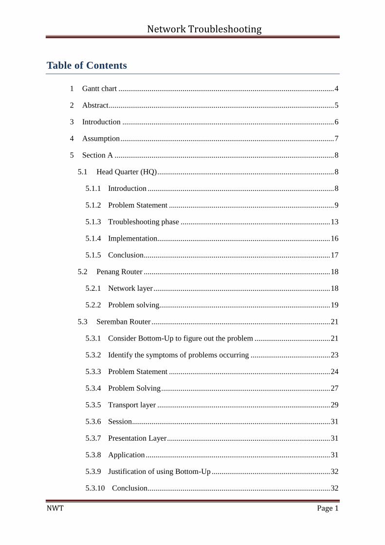
1 Gantt chart ............................................................................................................... 4
2 Abstract .................................................................................................................... 5
3 Introduction ............................................................................................................. 6
4 Assumption .............................................................................................................. 7
5 Section A ................................................................................................................. 8
5.1 Head Quarter (HQ) ........................................................................................... 8
5.1.1 Introduction ................................................................................................ 8
5.1.2 Problem Statement ..................................................................................... 9
5.1.3 Troubleshooting phase ............................................................................. 13
5.1.4 Implementation......................................................................................... 16
5.1.5 Conclusion ................................................................................................ 17
5.2 Penang Router ................................................................................................ 18
5.2.1 Network layer ........................................................................................... 18
5.2.2 Problem solving........................................................................................ 19
5.3 Seremban Router ............................................................................................ 21
5.3.1 Consider Bottom-Up to figure out the problem ....................................... 21
5.3.2 Identify the symptoms of problems occurring ......................................... 23
5.3.3 Problem Statement ................................................................................... 24
5.3.4 Problem Solving ....................................................................................... 27
5.3.5 Transport layer ......................................................................................... 29
5.3.6 Session ...................................................................................................... 31
5.3.7 Presentation Layer .................................................................................... 31
5.3.8 Application ............................................................................................... 31
5.3.9 Justification of using Bottom-Up ............................................................. 32
5.3.10 Conclusion .............................................................................................. 32
Network Troubleshooting
NWT Page 2
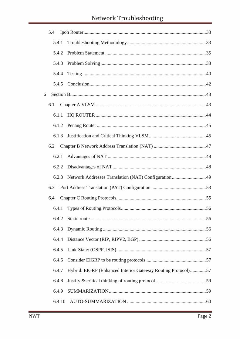
5.4 Ipoh Router ..................................................................................................... 33
5.4.1 Troubleshooting Methodology ................................................................. 33
5.4.2 Problem Statement ................................................................................... 35
5.4.3 Problem Solving ....................................................................................... 38
5.4.4 Testing ...................................................................................................... 40
5.4.5 Conclusion ................................................................................................ 42
6 Section B................................................................................................................ 43
6.1 Chapter A VLSM ........................................................................................... 43
6.1.1 HQ ROUTER ........................................................................................... 44
6.1.2 Penang Router .......................................................................................... 45
6.1.3 Justification and Critical Thinking VLSM ............................................... 45
6.2 Chapter B Network Address Translation (NAT) ........................................... 47
6.2.1 Advantages of NAT ................................................................................. 48
6.2.2 Disadvantages of NAT ............................................................................. 48
6.2.3 Network Addresses Translation (NAT) Configuration ............................ 49
6.3 Port Address Translation (PAT) Configuration ............................................. 53
6.4 Chapter C Routing Protocols.......................................................................... 55
6.4.1 Types of Routing Protocols ...................................................................... 56
6.4.2 Static route................................................................................................ 56
6.4.3 Dynamic Routing ..................................................................................... 56
6.4.4 Distance Vector (RIP, RIPV2, BGP) ....................................................... 56
6.4.5 Link-State: (OSPF, ISIS).......................................................................... 57
6.4.6 Consider EIGRP to be routing protocols ................................................. 57
6.4.7 Hybrid: EIGRP (Enhanced Interior Gateway Routing Protocol) ............. 57
6.4.8 Justify & critical thinking of routing protocol ......................................... 59
6.4.9 SUMMARIZATION ................................................................................ 59
6.4.10 AUTO-SUMMARIZATION ................................................................. 60
Network Troubleshooting
NWT Page 3
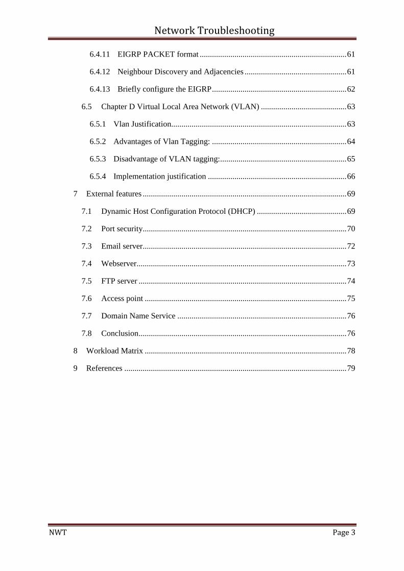
6.4.11 EIGRP PACKET format ........................................................................ 61
6.4.12 Neighbour Discovery and Adjacencies .................................................. 61
6.4.13 Briefly configure the EIGRP .................................................................. 62
6.5 Chapter D Virtual Local Area Network (VLAN) .......................................... 63
6.5.1 Vlan Justification...................................................................................... 63
6.5.2 Advantages of Vlan Tagging: .................................................................. 64
6.5.3 Disadvantage of VLAN tagging:.............................................................. 65
6.5.4 Implementation justification .................................................................... 66
7 External features .................................................................................................... 69
7.1 Dynamic Host Configuration Protocol (DHCP) ............................................ 69
7.2 Port security.................................................................................................... 70
7.3 Email server.................................................................................................... 72
7.4 Webserver....................................................................................................... 73
7.5 FTP server ...................................................................................................... 74
7.6 Access point ................................................................................................... 75
7.7 Domain Name Service ................................................................................... 76
7.8 Conclusion ...................................................................................................... 76
8 Workload Matrix ................................................................................................... 78
9 References ............................................................................................................. 79
Network Troubleshooting
NWT Page 4
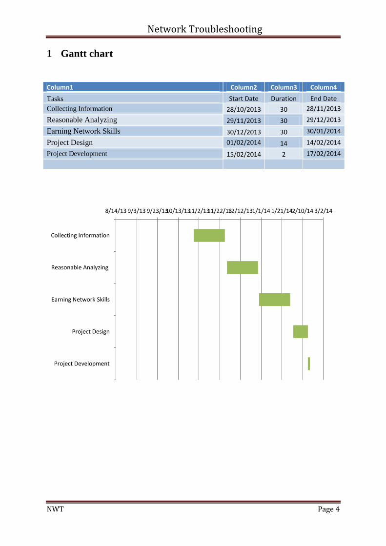
1 Gantt chart
8/14/13 9/3/13 9/23/13 10/13/13 11/2/13 11/22/13 12/12/13 1/1/14 1/21/14 2/10/14 3/2/14
Collecting Information
Reasonable Analyzing
Earning Network Skills
Project Design
Project Development
Column1 Column2 Column3 Column4
Tasks Start Date Duration End Date
Collecting Information 28/10/2013 30 28/11/2013
Reasonable Analyzing 29/11/2013 30 29/12/2013
Earning Network Skills 30/12/2013 30 30/01/2014
Project Design 01/02/2014 14 14/02/2014
Project Development 15/02/2014 2 17/02/2014
Network Troubleshooting
NWT Page 5
2 Abstract
It is two sections in this assignment (section A and section B). The section A is
required to find out the network problems, then troubleshooting the network problem, and
then design topology for the existing network. After that troubleshooting and design new
network without a problem, team should provide some suggestion for the company so the
network in the company becomes upgraded and it provides a better network environment for
the company. There are few solutions that help the company to upgrade their network, which
involves Public and Private IP with VLSM sub-netting, implement NAT/PAT, using a better
routing protocol and implement VLAN in the department. Consequently, the company does
not need to purchase and add tools to separate their departments.
Network Troubleshooting
NWT Page 6
3 Introduction
These days the network technology has become very popular to provide different
types of communications such as data and voice communication that significantly make
possible the business tasks. Certainly, sometimes some problems might happen in the
network that directs to interruption in that organization. In this case, the problems should be
identified first and then the suitable solutions should be given to repair the problems and
bring the network back in the stable state.
This project is determined on troubleshooting and fixing the issues of a network,
which is preceded in two sections. In the first step, the resent system will be analyzed and the
issues of the network will be identified and then based on the identified problems the suitable
solutions will be given. The next step is proceed with the offered recommendation in order to
improve the network performance, which is done by changing the arrangement and setting of
the network to avoid the additional expenses and extra purchases.
Network Troubleshooting
NWT Page 7
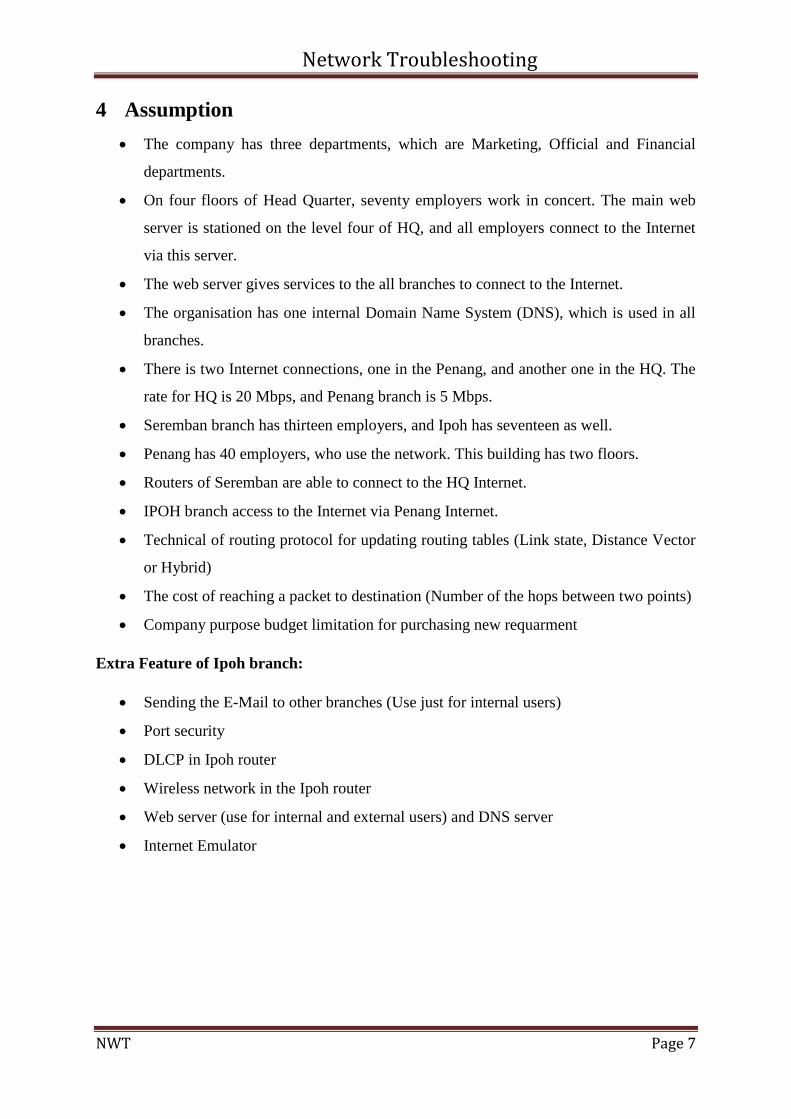
4 Assumption
The company has three departments, which are Marketing, Official and Financial
departments.
On four floors of Head Quarter, seventy employers work in concert. The main web
server is stationed on the level four of HQ, and all employers connect to the Internet
via this server.
The web server gives services to the all branches to connect to the Internet.
The organisation has one internal Domain Name System (DNS), which is used in all
branches.
There is two Internet connections, one in the Penang, and another one in the HQ. The
rate for HQ is 20 Mbps, and Penang branch is 5 Mbps.
Seremban branch has thirteen employers, and Ipoh has seventeen as well.
Penang has 40 employers, who use the network. This building has two floors.
Routers of Seremban are able to connect to the HQ Internet.
IPOH branch access to the Internet via Penang Internet.
Technical of routing protocol for updating routing tables (Link state, Distance Vector
or Hybrid)
The cost of reaching a packet to destination (Number of the hops between two points)
Company purpose budget limitation for purchasing new requarment
Extra Feature of Ipoh branch:
Sending the E-Mail to other branches (Use just for internal users)
Port security
DLCP in Ipoh router
Wireless network in the Ipoh router
Web server (use for internal and external users) and DNS server
Internet Emulator
Network Troubleshooting
NWT Page 8
5 Section A
5.1 Head Quarter (HQ)
5.1.1 Introduction
Recently a project in term of network troubleshooting between four geographical
points in Malaysia offered to our consultation team to find their problems and resolve those.
Meanwhile, the technical team should have investigation in first step to find out the current
situation base on routers' configuration files in a reverse engineering approach.
This project comprises a couple phases, the first one is fixing problem in current
network and eliminates all problems and network should be stable and get a fully work
situation.
The second part focuses on network improvement and increase related performance
along with adding some network technologies and protocols to boost traffic management and
make the network more efficient.
The project is running over four discrete geographical points that are KL, Ipoh,
Penang and Sembaran , HQ is located in Kuala Lumpur. This assignment only talks about
HQ router's issues.
Troubleshooting in part A will satisfied by Cisco troubleshooting process that
comprises seven steps also during those process some steps will integrated with each other in
unique stage.
"When you are troubleshooting a network environment, a systematic approach works
best. An unsystematic approach to troubleshooting can result in wasting valuable time and
resources, and can sometimes make symptoms even worse. Define the specific symptoms,
identify all potential problems that could be causing the symptoms, and then systematically
eliminate each potential problem (from most likely to least likely) until the symptoms
disappear." (Cisco, 2013)
Network Troubleshooting
NWT Page 9
5.1.2 Problem Statement
In term of problem statement, some users are complaining to IT department about
their connectivity issues, which needs to analyze process. First of all connectivity between
switches and routers are verified and no problem is determined there so some symptoms and
miss configuration probably happened in the four routers. Some of those potential problems
can be related to IP conflict, bad subnet masking in layer 3, clock rating layer 2 or even some
fault in layer 1 like port shut downing.
5.1.2.1 Investigation Report
In this phase two main objectives focuses on information gathering in deep and
finding probable causes for the failures.
According to investigator observation and scrutiny on the HQ router's configuration
file the following information could be achievement:
Router includes four physical ports, two of those are serial ports and rest of thos is
fast Ethernet ports.
The model of router is Cisco 2800 series with specification is attached in appendix
part.
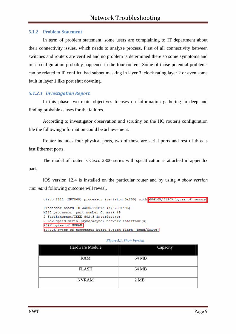
IOS version 12.4 is installed on the particular router and by using # show version
command following outcome will reveal.
Figure 5.1. Show Version
Hardware Module Capacity
RAM 64 MB
FLASH 64 MB
NVRAM 2 MB
Network Troubleshooting
NWT Page 10
For getting current process loading on the device # show process command is
triggered which result shows not abnormal process is running there.
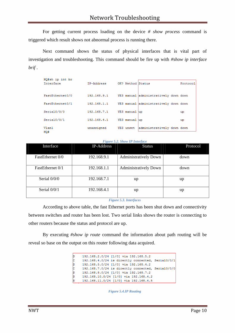
Next command shows the status of physical interfaces that is vital part of
investigation and troubleshooting. This command should be fire up with #show ip interface
brif .
Figure 5.2. Show IP Interface
Interface IP-Address Status Protocol
FastEthernet 0/0 192.168.9.1 Administratively Down down
FastEthernet 0/1 192.168.1.1 Administratively Down down
Serial 0/0/0 192.168.7.1 up up
Serial 0/0/1 192.168.4.1 up up
Figure 5.3. Interfaces
According to above table, the fast Ethernet ports has been shut down and connectivity
between switches and router has been lost. Two serial links shows the router is connecting to
other routers because the status and protocol are up.
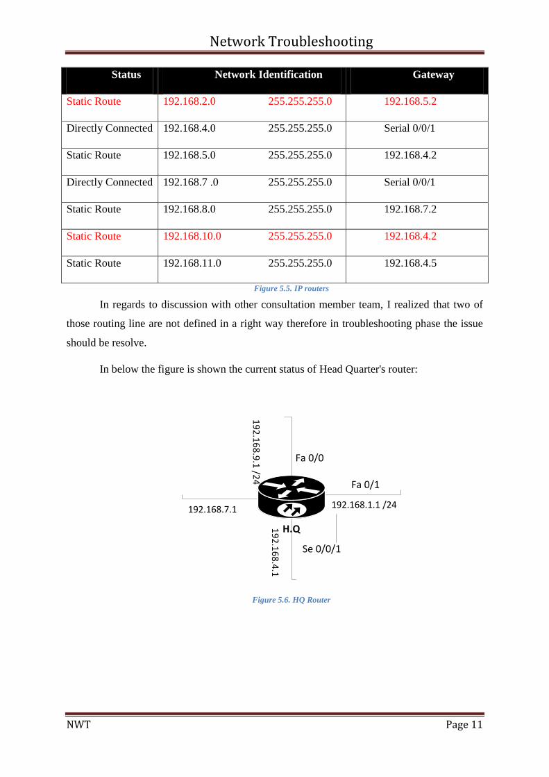
By executing #show ip route command the information about path routing will be
reveal so base on the output on this router following data acquired.
Figure 5.4.IP Routing
Network Troubleshooting
NWT Page 11
Status Network Identification Gateway
Static Route 192.168.2.0 255.255.255.0 192.168.5.2
Directly Connected 192.168.4.0 255.255.255.0 Serial 0/0/1
Static Route 192.168.5.0 255.255.255.0 192.168.4.2
Directly Connected 192.168.7 .0 255.255.255.0 Serial 0/0/1
Static Route 192.168.8.0 255.255.255.0 192.168.7.2
Static Route 192.168.10.0 255.255.255.0 192.168.4.2
Static Route 192.168.11.0 255.255.255.0 192.168.4.5
Figure 5.5. IP routers
In regards to discussion with other consultation member team, I realized that two of
those routing line are not defined in a right way therefore in troubleshooting phase the issue
should be resolve.
In below the figure is shown the current status of Head Quarter's router:
H.Q
Fa 0/0
Fa 0/1
Se 0/0/1
192.168.7.1
19
2.1
68
.4.1
192.168.1.1 /24
19
2.1
68
.9.1
/24
Figure 5.6. HQ Router
Network Troubleshooting
NWT Page 12
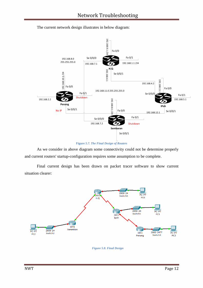
The current network design illustrates in below diagram:
H.Q
Fa 0/0
Fa 0/1Se 0/0/0
Se 0/0/1
19
2.1
68
.9.1
/24
192.168.1.1 /24192.168.7.1
19
2.1
68
.4.1
192.168.8.0
255.255.255.0
192.168.11.0 255.255.255.0
Penang
Fa 0/0
Fa 0/1
Se 0/0/1
192.168.2.2
19
2.1
68
.10
.1 /
24
Shutdown
No IP
Sembaran
Fa 0/0
Fa 0/1
Se 0/0/1
192.168.7.2
Se 0/0/0
19
2.1
68
.8.1
/24
Shutdown
IPoh
Fa 0/0
Fa 0/1
Se 0/0/1
192.168.4.2
192.168.5.1
192.168.12.1
Se 0/0/0
19
2.1
68
.11
.1
Figure 5.7. The Final Design of Routers
As we consider in above diagram some connectivity could not be determine properly
and current routers' startup-configuration requires some assumption to be complete.
Final current design has been drawn on packet tracer software to show current
situation clearer:
Figure 5.8. Final Design
Network Troubleshooting
NWT Page 13
5.1.3 Troubleshooting phase
In this stage, members will go through devise a plan to resolve the problems and
finally implement the proposed plan. In this case, of troubleshooting plan the technical
follows bottom-to-up methods to disappear symptoms.
5.1.3.1 Ethernet Interfaces
Address to collected information the H.Q router has two Fast-Ethernet ports (layer 2)
that are shut- down and in first step should turn those on.
Figure 5.9. Interfaces
As the result shows, the port has turned on and port is active so the next step is
checking IP addressing verification (Layer 3).
Figure 5.10. IP Interfaces
The result of layer 3 shows the interface is working properly and particular IP address
assigned to fastetherent0/0. In next step configure IP address in one of those clients in H.Q to
test the connectivity between client and router.
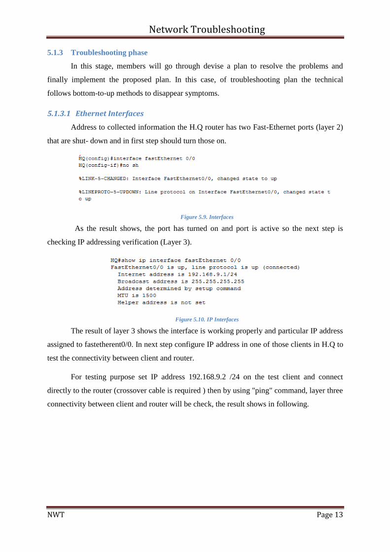
For testing purpose set IP address 192.168.9.2 /24 on the test client and connect
directly to the router (crossover cable is required ) then by using "ping" command, layer three
connectivity between client and router will be check, the result shows in following.
Network Troubleshooting
NWT Page 14
Figure 5.11. HQ Ping
Output message shows the connection between laptop and router is working properly
and ICMP replay messages are received by source. In addition, fastethernet 0/1 has been
troubleshooting in the same way.
5.1.3.2 Serial Interfaces
This step troubleshooting will pursuit by bottom-to-up method that explains layer one
to layer three OSI layers modeling. In layer one all cable and physical ports and connection
will be check. According to investigation step, the team realized that H.Q router is connected
to both Ipoh and Seremban.
The teams for testing in physical layer first check serial ports and circuit (CSU/DSU)
line relay on LOOPBACK testing method. In this particular test, we can do "both software
and hardware loopback tests on a CSU/DSU, a loopback plug is more effective to isolate
problems. A hardware loopback is able to prove that the entire CSU/DSU is not at fault."
(Cisco, 2008)
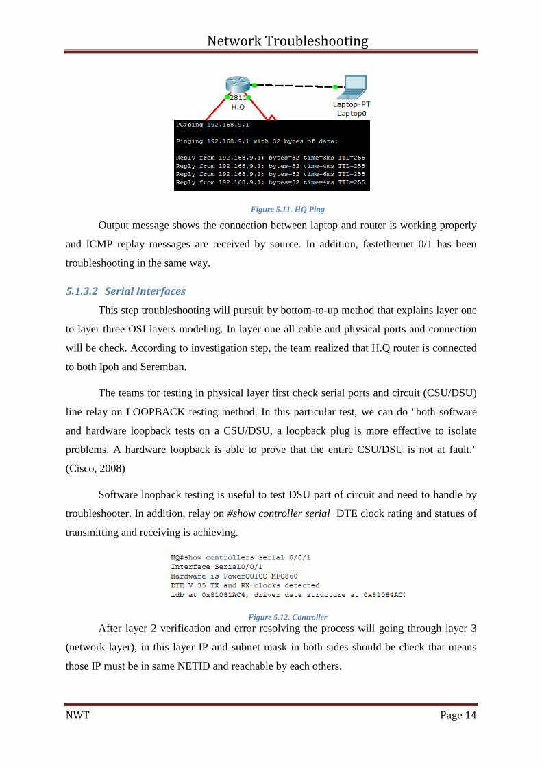
Software loopback testing is useful to test DSU part of circuit and need to handle by
troubleshooter. In addition, relay on #show controller serial DTE clock rating and statues of
transmitting and receiving is achieving.
Figure 5.12. Controller
After layer 2 verification and error resolving the process will going through layer 3
(network layer), in this layer IP and subnet mask in both sides should be check that means
those IP must be in same NETID and reachable by each others.
Network Troubleshooting
NWT Page 15
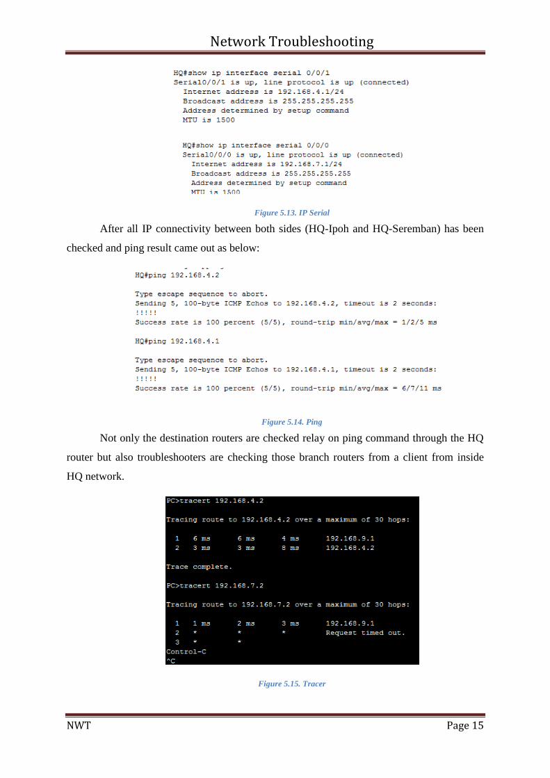
Figure 5.13. IP Serial
After all IP connectivity between both sides (HQ-Ipoh and HQ-Seremban) has been
checked and ping result came out as below:
Figure 5.14. Ping
Not only the destination routers are checked relay on ping command through the HQ
router but also troubleshooters are checking those branch routers from a client from inside
HQ network.
Figure 5.15. Tracer
Network Troubleshooting
NWT Page 16
Address to the output, Ipoh's router is reachable from HQ but Seremban's router is not
reachable and need to discussion with someone who is network administrator and responsible
in Seremban branch.
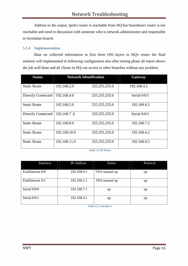
5.1.4 Implementation
Base on collected information in first three OSI layers in HQ's router the final
solution will implemented in following configuration also after testing phase all report shows
the job well done and all clients in HQ can access to other branches without any problem.
Status Network Identification Gateway
Static Route 192.168.2.0 255.255.255.0 192.168.4.2
Directly Connected 192.168.4.0 255.255.255.0 Serial 0/0/1
Static Route 192.168.5.0 255.255.255.0 192.168.4.2
Directly Connected 192.168.7 .0 255.255.255.0 Serial 0/0/1
Static Route 192.168.8.0 255.255.255.0 192.168.7.2
Static Route 192.168.10.0 255.255.255.0 192.168.4.2
Static Route 192.168.11.0 255.255.255.0 192.168.4.5
Table 5.1.IP Route
Interface IP-Address Status Protocol
FastEthernet 0/0 192.168.9.1 YES manual up up
FastEthernet 0/1 192.168.1.1 YES manual up up
Serial 0/0/0 192.168.7.1 up up
Serial 0/0/1 192.168.4.1 up up
Table 5.2. Interfaces
Network Troubleshooting
NWT Page 17
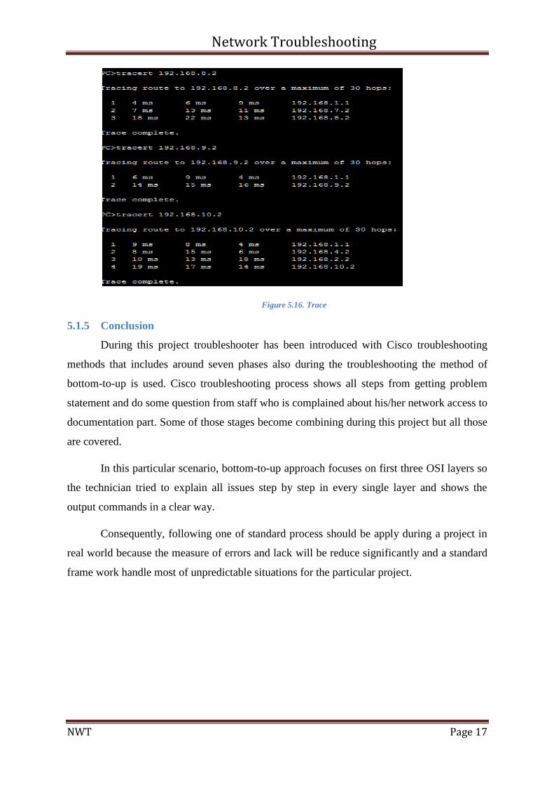
Figure 5.16. Trace
5.1.5 Conclusion
During this project troubleshooter has been introduced with Cisco troubleshooting
methods that includes around seven phases also during the troubleshooting the method of
bottom-to-up is used. Cisco troubleshooting process shows all steps from getting problem
statement and do some question from staff who is complained about his/her network access to
documentation part. Some of those stages become combining during this project but all those
are covered.
In this particular scenario, bottom-to-up approach focuses on first three OSI layers so
the technician tried to explain all issues step by step in every single layer and shows the
output commands in a clear way.
Consequently, following one of standard process should be apply during a project in
real world because the measure of errors and lack will be reduce significantly and a standard
frame work handle most of unpredictable situations for the particular project.
Network Troubleshooting
NWT Page 18
5.2 Penang Router
At this router, the users are able to ping each other but they cannot access the external
network. The users are facing issues with the default gateway address and they cannot ping
external networks. The range of the network is 192.168.10.0/192.168.2.0
5.2.1 Network layer
Problem Statement of Penang router
In order to get the information from the router a command is used which is #show
startup-config. By using this command, the users can get to the configuration of the area on
the networks. Some of the problems in the configuration part in the current system are:
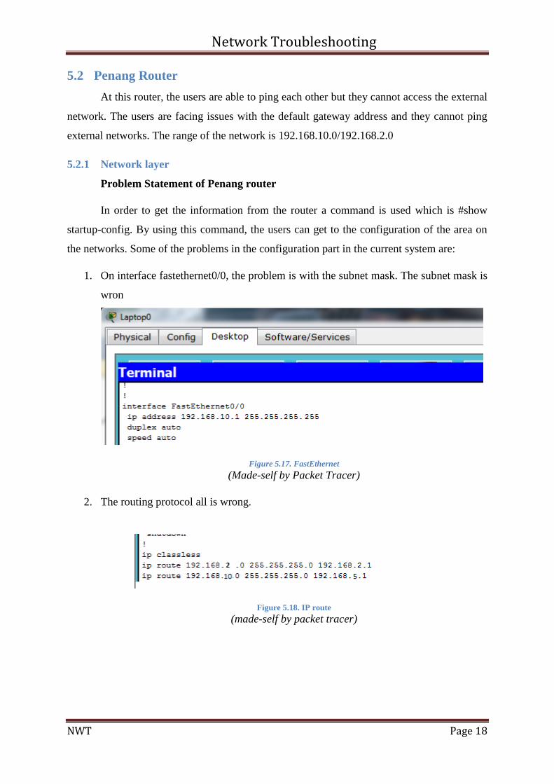
1. On interface fastethernet0/0, the problem is with the subnet mask. The subnet mask is
wron
Figure 5.17. FastEthernet
(Made-self by Packet Tracer)
2. The routing protocol all is wrong.
Figure 5.18. IP route
(made-self by packet tracer)
Network Troubleshooting
NWT Page 19
5.2.2 Problem solving
Solutions
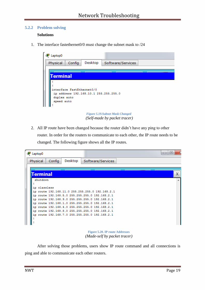
1. The interface fastethernet0/0 must change the subnet mask to /24
Figure 5.19.Subnet Mask Changed
(Self-made by packet tracer)
2. All IP route have been changed because the router didn’t have any ping to other
router. In order for the routers to communicate to each other, the IP route needs to be
changed. The following figure shows all the IP routes.
Figure 5.20. IP route Addresses
(Made-self by packet tracer)
After solving those problems, users show IP route command and all connections is
ping and able to communicate each other routers.
Network Troubleshooting
NWT Page 20
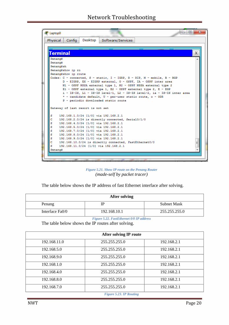
Figure 5.21. Show IP route on the Penang Router
(made-self by packet tracer)
The table below shows the IP address of fast Ethernet interface after solving.
After solving
Penang IP Subnet Mask
Interface Fa0/0 192.168.10.1 255.255.255.0
Figure 5.22. FastEthernet 0/0 IP address
The table below shows the IP routes after solving.
After solving IP route
192.168.11.0 255.255.255.0 192.168.2.1
192.168.5.0 255.255.255.0 192.168.2.1
192.168.9.0 255.255.255.0 192.168.2.1
192.168.1.0 255.255.255.0 192.168.2.1
192.168.4.0 255.255.255.0 192.168.2.1
192.168.8.0 255.255.255.0 192.168.2.1
192.168.7.0 255.255.255.0 192.168.2.1
Figure 5.23. IP Routing
Network Troubleshooting
NWT Page 21
5.3 Seremban Router
5.3.1 Consider Bottom-Up to figure out the problem
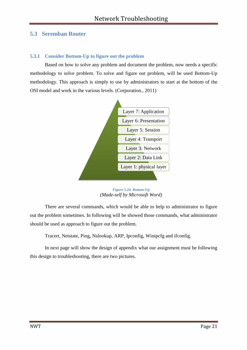
Based on how to solve any problem and document the problem, now needs a specific
methodology to solve problem. To solve and figure out problem, will be used Bottom-Up
methodology. This approach is simply to use by administrators to start at the bottom of the
OSI model and work in the various levels. (Corporation., 2011)
Figure 5.24. Buttom-Up
(Made-self by Microsoft Word)
There are several commands, which would be able to help to administrator to figure
out the problem sometimes. In following will be showed those commands, what administrator
should be used as approach to figure out the problem.
Tracert, Netstate, Ping, Nslookup, ARP, Ipconfig, Winipcfg and ifconfig.
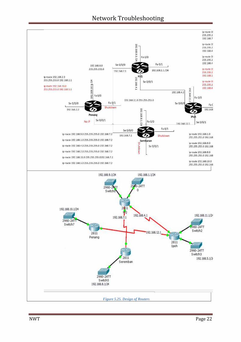
In next page will show the design of appendix what our assignment must be following
this design to troubleshooting, there are two pictures.
Layer 7: Application
Layer 6: Presentation
Layer 5: Session
Layer 4: Transport
Layer 3: Network
Layer 2: Data Link
Layer 1: physical layer
Network Troubleshooting
NWT Page 22
Figure 5.25. Design of Routers
Network Troubleshooting
NWT Page 23
Base on Appendix A what university gave; the network will be appear in mind same
as above picture. The OSI model is a systematic of troubleshooting a network. There are
three steps which researcher was following them; 1) Define the problem 2) Isolate the cause
of problem 3) solve the problem.
At each steps researcher has been done a document; Note all steps, what have done
and the final result to recover overall experience. Record what have done, have fallback and
make a proposal of history for the group. (Corporation., 2011)
5.3.2 Identify the symptoms of problems occurring
There are three types of symptoms which will be showing in following and all
problems would be occurred by those three symptoms. The Bottom-Up methodology will
show problems in three symptoms via each layer. The symptom is divided into three parts;
(Tomsho, 2011)
1) User symptoms
2) Network symptoms
3) End-User symptoms
Physical layer causes
1) Have been checked the equipment at end distant all powered on.
2) Cables was checked, there was not any damaged and no defects.
3) The maximum length of an Ethernet segment was 100 meters.
4) All connector cables were inserted into the network.
5) All port indicators were on at SEREMBAN router.
6) Have been checked types of cables that should be used between systems.
7) There was not any suspecting on hardware because have been used Packet Tracer.
No problem figured out.
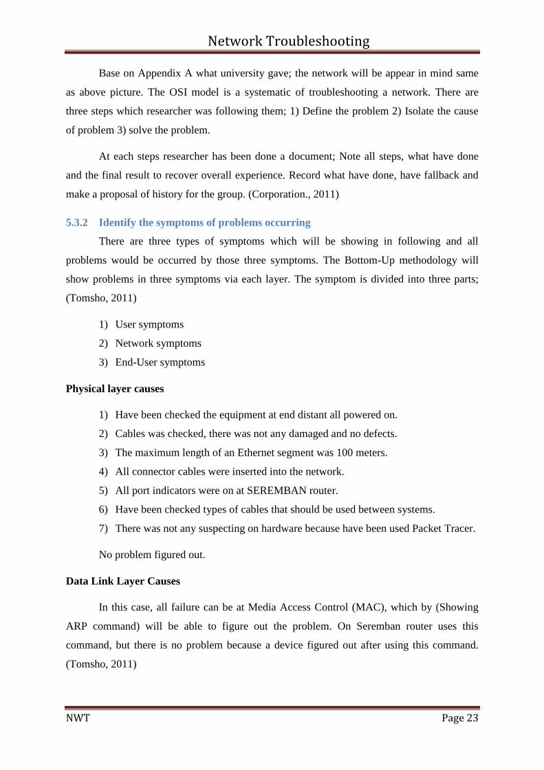
Data Link Layer Causes
In this case, all failure can be at Media Access Control (MAC), which by (Showing
ARP command) will be able to figure out the problem. On Seremban router uses this
command, but there is no problem because a device figured out after using this command.
(Tomsho, 2011)
Network Troubleshooting
NWT Page 24
Figure 5.26. ARP Command
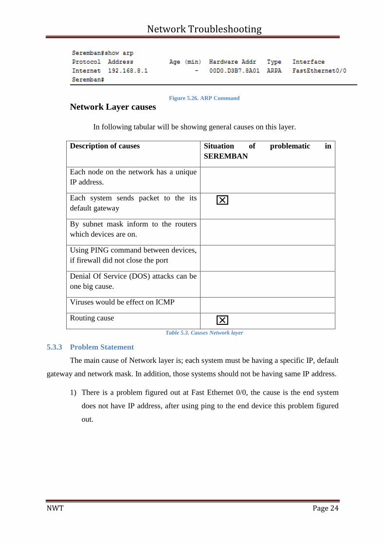
Network Layer causes
In following tabular will be showing general causes on this layer.
Description of causes Situation of problematic in
SEREMBAN
Each node on the network has a unique
IP address.
Each system sends packet to the its
default gateway
By subnet mask inform to the routers
which devices are on.
Using PING command between devices,
if firewall did not close the port
Denial Of Service (DOS) attacks can be
one big cause.
Viruses would be effect on ICMP
Routing cause
Table 5.3. Causes Network layer
5.3.3 Problem Statement
The main cause of Network layer is; each system must be having a specific IP, default
gateway and network mask. In addition, those systems should not be having same IP address.
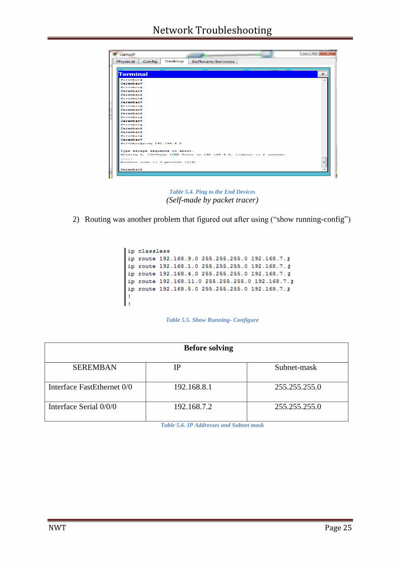
1) There is a problem figured out at Fast Ethernet 0/0, the cause is the end system
does not have IP address, after using ping to the end device this problem figured
out.
Network Troubleshooting
NWT Page 25
Table 5.4. Ping to the End Devices
(Self-made by packet tracer)
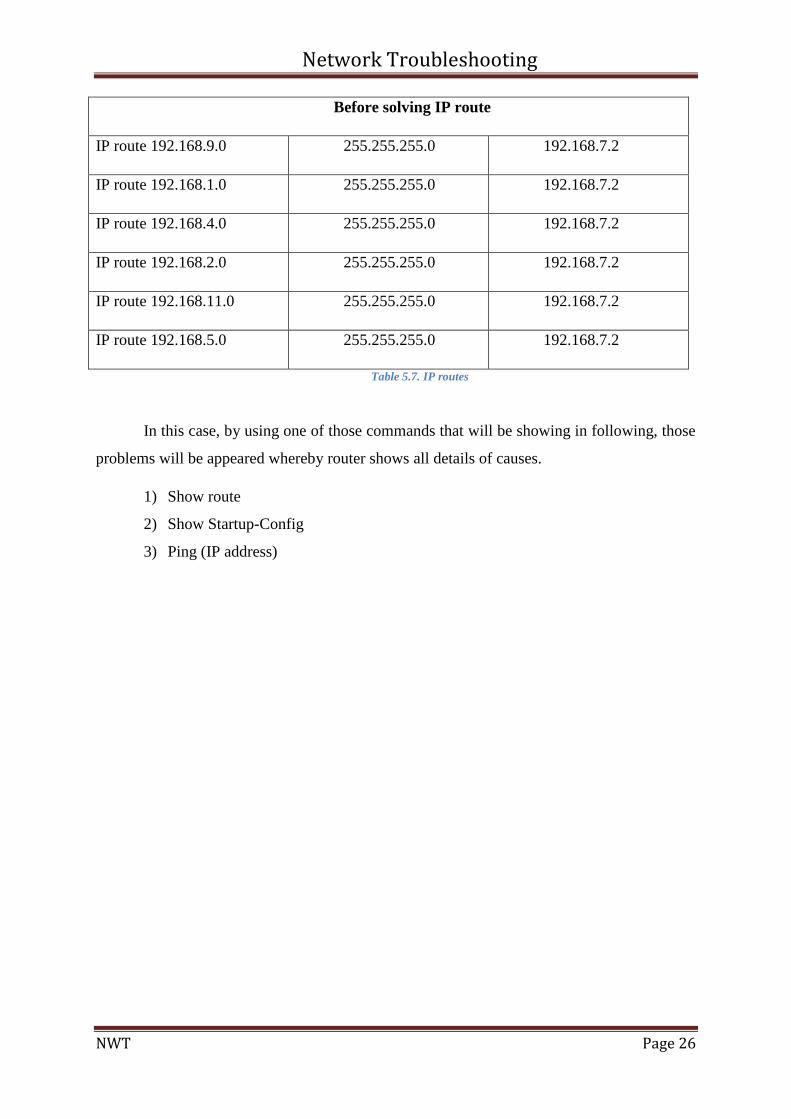
2) Routing was another problem that figured out after using (“show running-config”)
Table 5.5. Show Running- Configure
Before solving
SEREMBAN IP Subnet-mask
Interface FastEthernet 0/0 192.168.8.1 255.255.255.0
Interface Serial 0/0/0 192.168.7.2 255.255.255.0
Table 5.6. IP Addresses and Subnet mask
Network Troubleshooting
NWT Page 26
Before solving IP route
IP route 192.168.9.0 255.255.255.0 192.168.7.2
IP route 192.168.1.0 255.255.255.0 192.168.7.2
IP route 192.168.4.0 255.255.255.0 192.168.7.2
IP route 192.168.2.0 255.255.255.0 192.168.7.2
IP route 192.168.11.0 255.255.255.0 192.168.7.2
IP route 192.168.5.0 255.255.255.0 192.168.7.2
Table 5.7. IP routes
In this case, by using one of those commands that will be showing in following, those
problems will be appeared whereby router shows all details of causes.
1) Show route
2) Show Startup-Config
3) Ping (IP address)
Network Troubleshooting
NWT Page 27
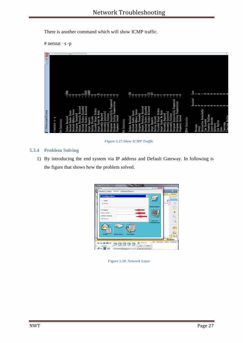
There is another command which will show ICMP traffic.
# netstat –s -p
Figure 5.27.Show ICMP Traffic
5.3.4 Problem Solving
1) By introducing the end system via IP address and Default Gateway. In following is
the figure that shows how the problem solved.
Figure 5.28. Network Layer
Network Troubleshooting
NWT Page 28
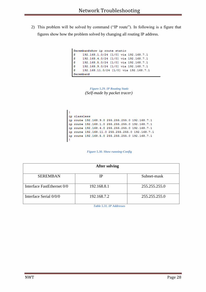
2) This problem will be solved by command (“IP route”). In following is a figure that
figures show how the problem solved by changing all routing IP address.
Figure 5.29. IP Routing Static
(Self-made by packet tracer)
Figure 5.30. Show running-Config
After solving
SEREMBAN IP Subnet-mask
Interface FastEthernet 0/0 192.168.8.1 255.255.255.0
Interface Serial 0/0/0 192.168.7.2 255.255.255.0
Table 5.31. IP Addresses
Network Troubleshooting
NWT Page 29
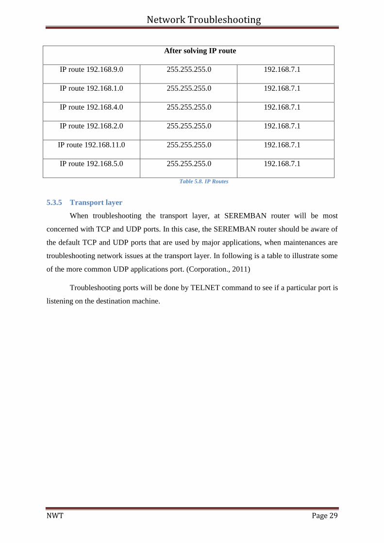
After solving IP route
IP route 192.168.9.0 255.255.255.0 192.168.7.1
IP route 192.168.1.0 255.255.255.0 192.168.7.1
IP route 192.168.4.0 255.255.255.0 192.168.7.1
IP route 192.168.2.0 255.255.255.0 192.168.7.1
IP route 192.168.11.0 255.255.255.0 192.168.7.1
IP route 192.168.5.0 255.255.255.0 192.168.7.1
Table 5.8. IP Routes
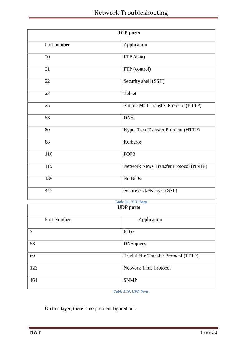
5.3.5 Transport layer
When troubleshooting the transport layer, at SEREMBAN router will be most
concerned with TCP and UDP ports. In this case, the SEREMBAN router should be aware of
the default TCP and UDP ports that are used by major applications, when maintenances are
troubleshooting network issues at the transport layer. In following is a table to illustrate some
of the more common UDP applications port. (Corporation., 2011)
Troubleshooting ports will be done by TELNET command to see if a particular port is
listening on the destination machine.
Network Troubleshooting
NWT Page 30
TCP ports
Port number Application
20 FTP (data)
21 FTP (control)
22 Security shell (SSH)
23 Telnet
25 Simple Mail Transfer Protocol (HTTP)
53 DNS
80 Hyper Text Transfer Protocol (HTTP)
88 Kerberos
110 POP3
119 Network News Transfer Protocol (NNTP)
139 NetBiOs
443 Secure sockets layer (SSL)
Table 5.9. TCP Ports
UDP ports
Port Number Application
7 Echo
53 DNS query
69 Trivial File Transfer Protocol (TFTP)
123 Network Time Protocol
161 SNMP
Table 5.10. UDP Ports
On this layer, there is no problem figured out.
Network Troubleshooting
NWT Page 31
5.3.6 Session
Issues rarely occur at this layer. This layer is responsible for end-to-end
communication between applications. Data units at this layer are commonly called protocol
data units (PDU). Session-layer protocols can operate in connectionless mode or connection-
oriented mode. Session-layer connections facilitate the orderly exchange of data between
applications. The session layer maintains a conversation over many of bursts of data. One of
the most problems at this layer that can be an example of spies exchanging message. They
would have to establish an order of operations that would be used to pass encoded messages
back and forth which it does not happening at SEREMBAN area. Another example can be
using Remote Desktop that maintenance wants to start this layer for Remote to another
computer. (Tomsho, 2011)
5.3.7 Presentation Layer
This layer same as Session layer issues rarely occur at this layer. This layer provides
services to the applications layer. The presentation layer provides translation services as
necessary to communicate requests to and from the Application Layer by establishing
communication with the peer Presentation Layer in a distant network resource and reaching
agreement on a common syntax and any data compression for transfers. No problem figured
out. (Tomsho, 2011)
5.3.8 Application
The application layer will check where the client-server has issues occurred. Those
issues would be act on SMTP, POP3, HTTP, FTP and etc. protocols.
Another part to troubleshooting at this layer is Domain Name Service (DNS). The
DNS translate host name into IP addresses. If user uses host name, the DNS should be
respond with an IP address. In this particular case, if the DNS does not respond, problem
would be DNS troubleshooting, which is beyond the scope of this assignment, but at
SEREMBAN does not have this problem. (Corporation., 2011)
Network Troubleshooting
NWT Page 32
5.3.9 Justification of using Bottom-Up
After researching and compare between Cisco and Button-Up, researcher consider the
Button-Up to figure out those problems because of the researcher is novice and in this
particular case we need to gathering many information of all layers and also to figure out all
causes. The Button-Up was use full because of novice able to figure out by causes what
relatives to each layer. Each layer has its own causes and base on those causes able to figure
out problems. In following are advantages of Button-Up; (Corporation., 2011)
1) Scalability: In this case, can add user if network management needs.
2) Easier Troubleshooting: If any component at one layer fails, this approach will
show the component target.
3) Interoperability; Computerized devices from multiple vendors can work the same
network; this is by creating products to meet the same networking standards. It
encourages industry standardization by defining what functions occur at each
layer of the model.
5.3.10 Conclusion
As researcher learned, that network troubleshooting would be quite involved the OSI
layer. In this case, the symptoms of the issue will be act to how maintenance approaches it.
Such as, as long as there is ping to the remote systems then maintenance able to
troubleshooting up the OSI model. (Corporation., 2011)
Network Troubleshooting
NWT Page 33
5.4 Ipoh Router
5.4.1 Troubleshooting Methodology
One of the most important tasks that one network administrator should have is
network troubleshooting. The problems can be so serious and leads the network to goes
down, and some of them can be solved in a minute. There are different approaches and
methodologies for troubleshooting the network problems and definitely the base of all these
approaches is the seven layers of Open Systems Interconnection (OSI) model. Thus, the
significance of the OSI layer is clear and if any problem happens to each process of OSI layer
the traffic cannot be run on the network and directs to the trouble of the network (Ranjbar,
2010). The methodology has been chosen for this project is Cisco Troubleshooting
Methodology. This methodology has been chosen, because other methodologies need
experience, and they are complicated. Also, in making documentation the best methodology
can be chosen is Cisco troubleshooting, which has eight steps to troubleshoot the current
project (Cisco, 2013). These are the eight steps of this methodology:
1. Identify the problem.
2. Collect detailed information.
3. Consider possible reasons for the failures.
4. Set up a plan to solve the problem.
5. Implement the plan.
6. Monitor the results of the implementation.
7. Repeat the above processes if the plan does not determine the problem.
8. Finally, document and modify the changes to solve the problem.
Gathering Symptoms: This step proceeds to recognize the problem by getting
information from the users of the system when a distraction report is given. To identify the
problems, administrators should rely on some tools such as trace, ping, or a network monitor.
If the data about the problems was not enough, should get some information from the users.
After identifying the problems should consider the possible solutions to solve the problems.
Connectivity issues can be very difficult to trace to a single point of failure. In most
situations, there are several possible causes for a network error, and the administrator should
identify each probable cause.
Isolate the problem: The next step is produced and developed a solution or action
plan. It is critical to carefully analyse the planned solution and find the possible solution may
Network Troubleshooting
NWT Page 34
have. These are some of the ways can have to solve the problem carefully. For instance,
making one change at a time to solve those problems, which have the least impact on the
users. The other one is, does not create security holes of implementing the changes. Finally,
administrators should be sure to can go back of any changes they made.
Monitor the results of the solution and check the fact-gathering phase and establish
that the solution solved the problem. However, if the trouble still exists, find the possible
causes and effort to resolve the next cause of the problem. At the end, solve problems before
they happen and affect the users is the best solution for the network. The only way to do is to
offer time to creating baselines for your network and to continuously monitor your network
for changes.
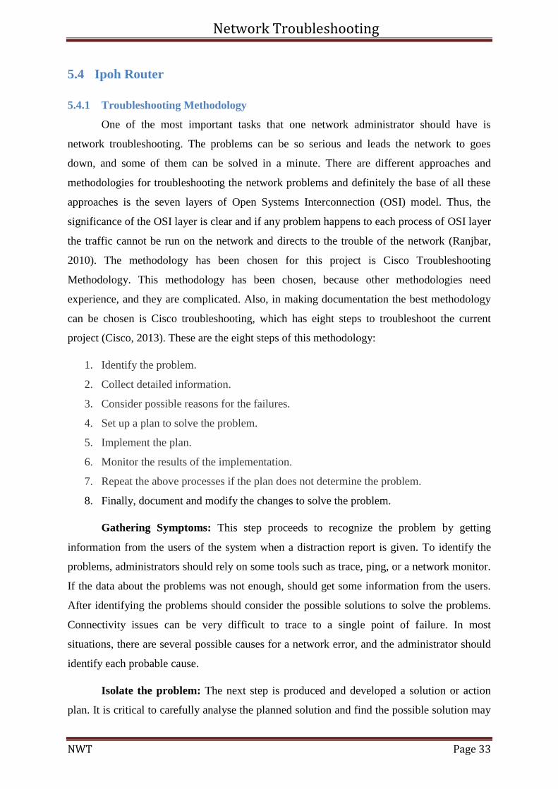
The troubleshooting method begins the process from layer 1(physical layer), this
method is used when the physical layer seems to be the source of the problem (Ranjbar,
2010).
Figure 5.32. OSI Seven Layers
(http://bansantosh.blogspot.com/2013/02/the-7-layers-of-osi-model.html)
Network Troubleshooting
NWT Page 35
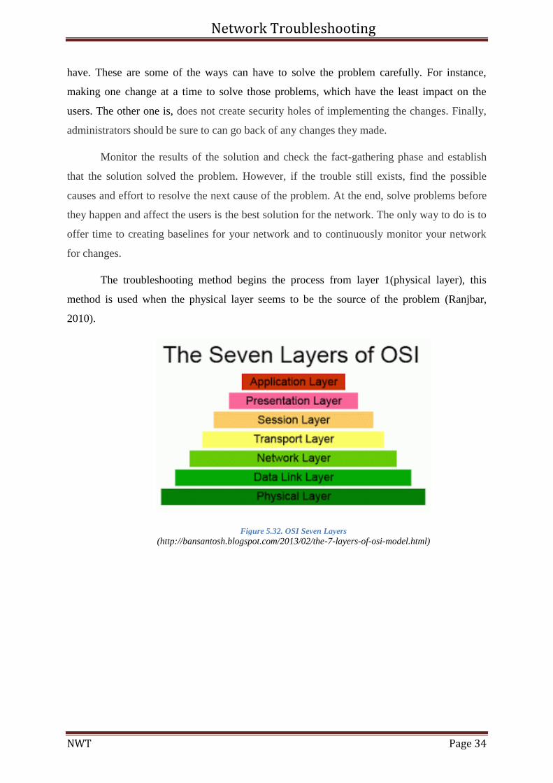
Figure 5.33. Ipoh Router
Router of Ipoh consists of two networks, which are running in the area. There is two
networks of 192.168.11.0 network and 192.168.5.0.
IP Address Subnet Mask Network
192.168.11.1 255.255.255.0 192.168.11.0
192.168.5.1 255.255.255.0 192.168.5.0
Figure 5.34. Assigned IP for the PCs
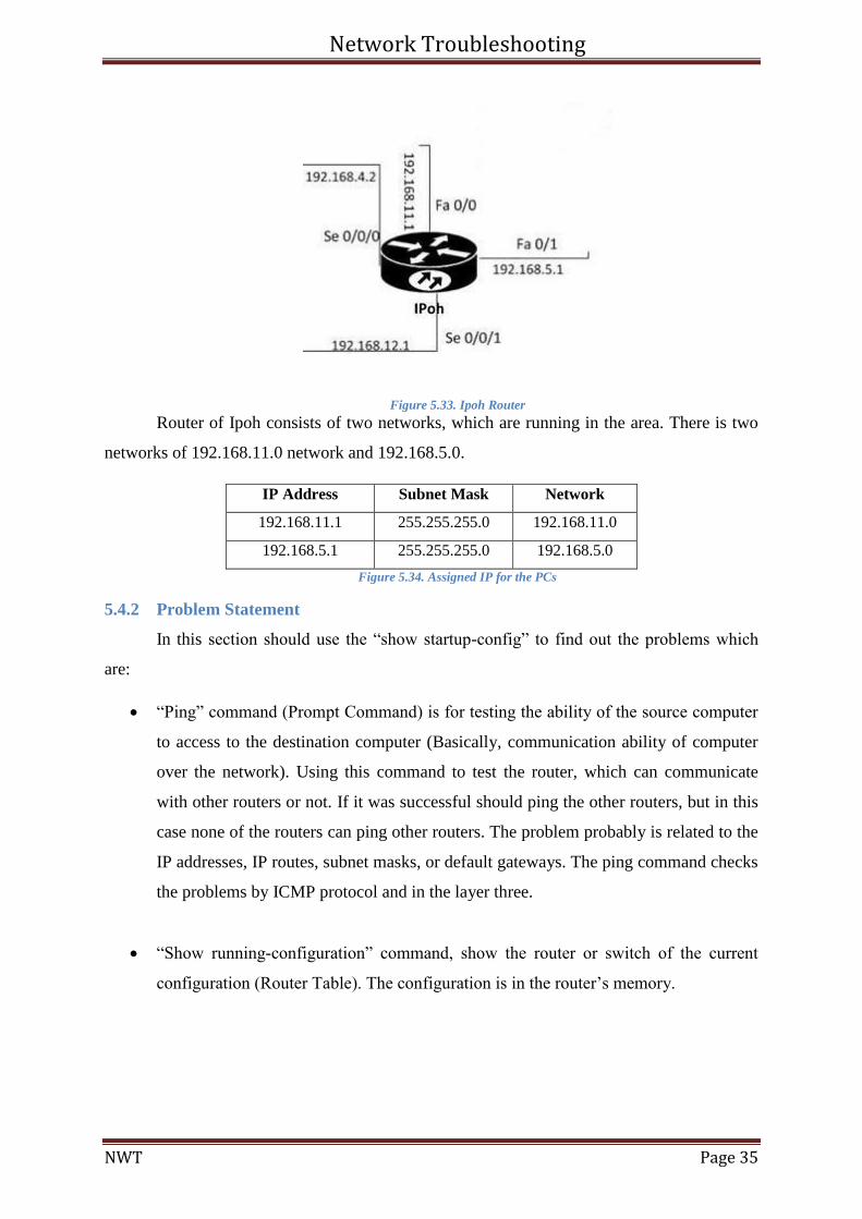
5.4.2 Problem Statement
In this section should use the “show startup-config” to find out the problems which
are:
“Ping” command (Prompt Command) is for testing the ability of the source computer
to access to the destination computer (Basically, communication ability of computer
over the network). Using this command to test the router, which can communicate
with other routers or not. If it was successful should ping the other routers, but in this
case none of the routers can ping other routers. The problem probably is related to the
IP addresses, IP routes, subnet masks, or default gateways. The ping command checks
the problems by ICMP protocol and in the layer three.
“Show running-configuration” command, show the router or switch of the current
configuration (Router Table). The configuration is in the router’s memory.
Network Troubleshooting
NWT Page 36
Ipoh>enable
Ipoh#show startup-config
!
hostname Ipoh
!
interface FastEthernet0/0
ip address 192.168.11.1 255.255.0.0
!
interface FastEthernet0/1
ip address 192.168.5.1 255.255.255.0
!
interface Serial0/0/0
ip address 192.168.4.2 255.255.0.0
!
interface Serial0/0/1
ip address 192.168.12.1 255.255.255.0
shutdown
!ip route 192.168.1.0 255.255.255.0 192.168.4.1
ip route 192.168.8.0 255.255.255.0 192.168.4.3
ip route 192.168.8.0 255.255.255.0 192.168.4.1
ip route 192.168.10.0 255.255.255.0 192.168.2.2
!
end Figure 5.35.Show run the router
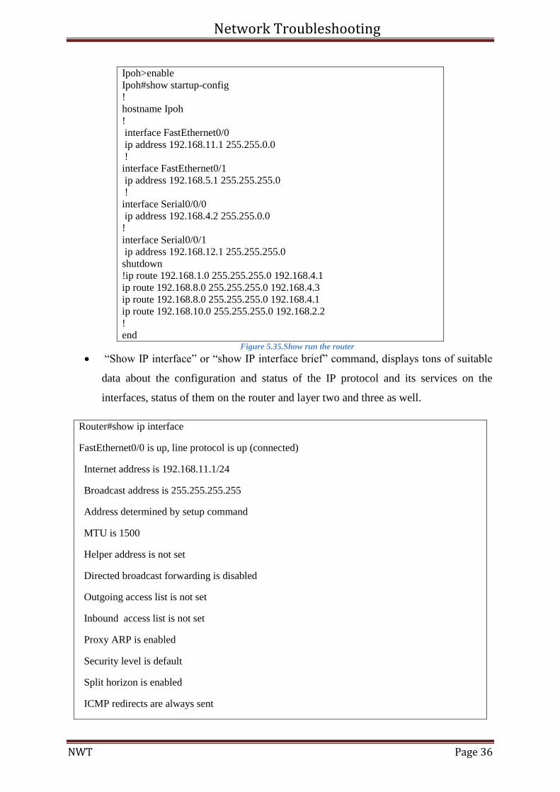
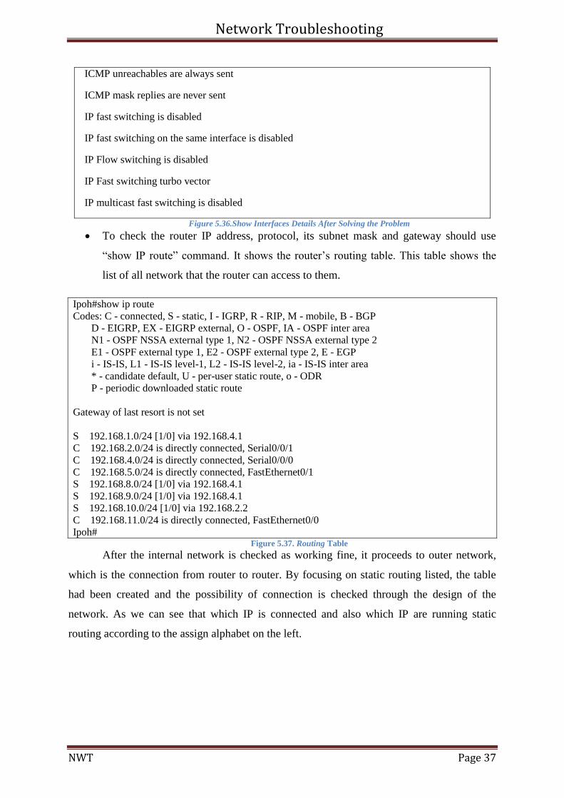
“Show IP interface” or “show IP interface brief” command, displays tons of suitable
data about the configuration and status of the IP protocol and its services on the
interfaces, status of them on the router and layer two and three as well.
Router#show ip interface
FastEthernet0/0 is up, line protocol is up (connected)
Internet address is 192.168.11.1/24
Broadcast address is 255.255.255.255
Address determined by setup command
MTU is 1500
Helper address is not set
Directed broadcast forwarding is disabled
Outgoing access list is not set
Inbound access list is not set
Proxy ARP is enabled
Security level is default
Split horizon is enabled
ICMP redirects are always sent
Network Troubleshooting
NWT Page 37
ICMP unreachables are always sent
ICMP mask replies are never sent
IP fast switching is disabled
IP fast switching on the same interface is disabled
IP Flow switching is disabled
IP Fast switching turbo vector
IP multicast fast switching is disabled
Figure 5.36.Show Interfaces Details After Solving the Problem
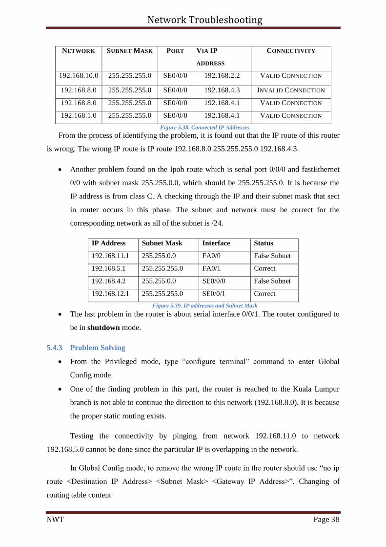
To check the router IP address, protocol, its subnet mask and gateway should use
“show IP route” command. It shows the router’s routing table. This table shows the
list of all network that the router can access to them.
Ipoh#show ip route
Codes: C - connected, S - static, I - IGRP, R - RIP, M - mobile, B - BGP
D - EIGRP, EX - EIGRP external, O - OSPF, IA - OSPF inter area
N1 - OSPF NSSA external type 1, N2 - OSPF NSSA external type 2
E1 - OSPF external type 1, E2 - OSPF external type 2, E - EGP
i - IS-IS, L1 - IS-IS level-1, L2 - IS-IS level-2, ia - IS-IS inter area
* - candidate default, U - per-user static route, o - ODR
P - periodic downloaded static route
Gateway of last resort is not set
S 192.168.1.0/24 [1/0] via 192.168.4.1
C 192.168.2.0/24 is directly connected, Serial0/0/1
C 192.168.4.0/24 is directly connected, Serial0/0/0
C 192.168.5.0/24 is directly connected, FastEthernet0/1
S 192.168.8.0/24 [1/0] via 192.168.4.1
S 192.168.9.0/24 [1/0] via 192.168.4.1
S 192.168.10.0/24 [1/0] via 192.168.2.2
C 192.168.11.0/24 is directly connected, FastEthernet0/0
Ipoh# Figure 5.37. Routing Table
After the internal network is checked as working fine, it proceeds to outer network,
which is the connection from router to router. By focusing on static routing listed, the table
had been created and the possibility of connection is checked through the design of the
network. As we can see that which IP is connected and also which IP are running static
routing according to the assign alphabet on the left.
Network Troubleshooting
NWT Page 38
NETWORK SUBNET MASK PORT VIA IP
ADDRESS
CONNECTIVITY
192.168.10.0 255.255.255.0 SE0/0/0 192.168.2.2 VALID CONNECTION
192.168.8.0 255.255.255.0 SE0/0/0 192.168.4.3 INVALID CONNECTION
192.168.8.0 255.255.255.0 SE0/0/0 192.168.4.1 VALID CONNECTION
192.168.1.0 255.255.255.0 SE0/0/0 192.168.4.1 VALID CONNECTION
Figure 5.38. Connected IP Addresses
From the process of identifying the problem, it is found out that the IP route of this router
is wrong. The wrong IP route is IP route 192.168.8.0 255.255.255.0 192.168.4.3.
Another problem found on the Ipoh route which is serial port 0/0/0 and fastEthernet
0/0 with subnet mask 255.255.0.0, which should be 255.255.255.0. It is because the
IP address is from class C. A checking through the IP and their subnet mask that sect
in router occurs in this phase. The subnet and network must be correct for the
corresponding network as all of the subnet is /24.
IP Address Subnet Mask Interface Status
192.168.11.1 255.255.0.0 FA0/0 False Subnet
192.168.5.1 255.255.255.0 FA0/1 Correct
192.168.4.2 255.255.0.0 SE0/0/0 False Subnet
192.168.12.1 255.255.255.0 SE0/0/1 Correct
Figure 5.39. IP addresses and Subnet Mask
The last problem in the router is about serial interface 0/0/1. The router configured to
be in shutdown mode.
5.4.3 Problem Solving
From the Privileged mode, type “configure terminal” command to enter Global
Config mode.
One of the finding problem in this part, the router is reached to the Kuala Lumpur
branch is not able to continue the direction to this network (192.168.8.0). It is because
the proper static routing exists.
Testing the connectivity by pinging from network 192.168.11.0 to network
192.168.5.0 cannot be done since the particular IP is overlapping in the network.
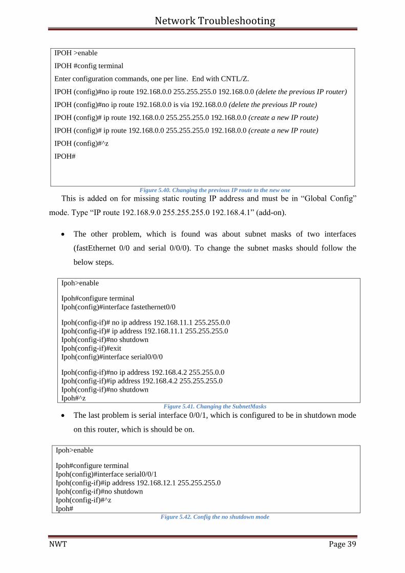
In Global Config mode, to remove the wrong IP route in the router should use “no ip
route <Destination IP Address> <Subnet Mask> <Gateway IP Address>”. Changing of
routing table content
Network Troubleshooting
NWT Page 39
IPOH >enable
IPOH #config terminal
Enter configuration commands, one per line. End with CNTL/Z.
IPOH (config)#no ip route 192.168.0.0 255.255.255.0 192.168.0.0 (delete the previous IP router)
IPOH (config)#no ip route 192.168.0.0 is via 192.168.0.0 (delete the previous IP route)
IPOH (config)# ip route 192.168.0.0 255.255.255.0 192.168.0.0 (create a new IP route)
IPOH (config)# ip route 192.168.0.0 255.255.255.0 192.168.0.0 (create a new IP route)
IPOH (config)#^z
IPOH#
Figure 5.40. Changing the previous IP route to the new one
This is added on for missing static routing IP address and must be in “Global Config”
mode. Type “IP route 192.168.9.0 255.255.255.0 192.168.4.1” (add-on).
The other problem, which is found was about subnet masks of two interfaces
(fastEthernet 0/0 and serial 0/0/0). To change the subnet masks should follow the
below steps.
Ipoh>enable
Ipoh#configure terminal
Ipoh(config)#interface fastethernet0/0
Ipoh(config-if)# no ip address 192.168.11.1 255.255.0.0
Ipoh(config-if)# ip address 192.168.11.1 255.255.255.0
Ipoh(config-if)#no shutdown
Ipoh(config-if)#exit
Ipoh(config)#interface serial0/0/0
Ipoh(config-if)#no ip address 192.168.4.2 255.255.0.0
Ipoh(config-if)#ip address 192.168.4.2 255.255.255.0
Ipoh(config-if)#no shutdown
Ipoh#^z Figure 5.41. Changing the SubnetMasks
The last problem is serial interface 0/0/1, which is configured to be in shutdown mode
on this router, which is should be on.
Ipoh>enable
Ipoh#configure terminal
Ipoh(config)#interface serial0/0/1
Ipoh(config-if)#ip address 192.168.12.1 255.255.255.0
Ipoh(config-if)#no shutdown
Ipoh(config-if)#^z
Ipoh# Figure 5.42. Config the no shutdown mode
Network Troubleshooting
NWT Page 40
5.4.4 Testing
After change the whole mistakes in the router can use ping command to test the
system and find out the changes are correct and all other branches can ping with the Ipoh
branch successfully or they fail.
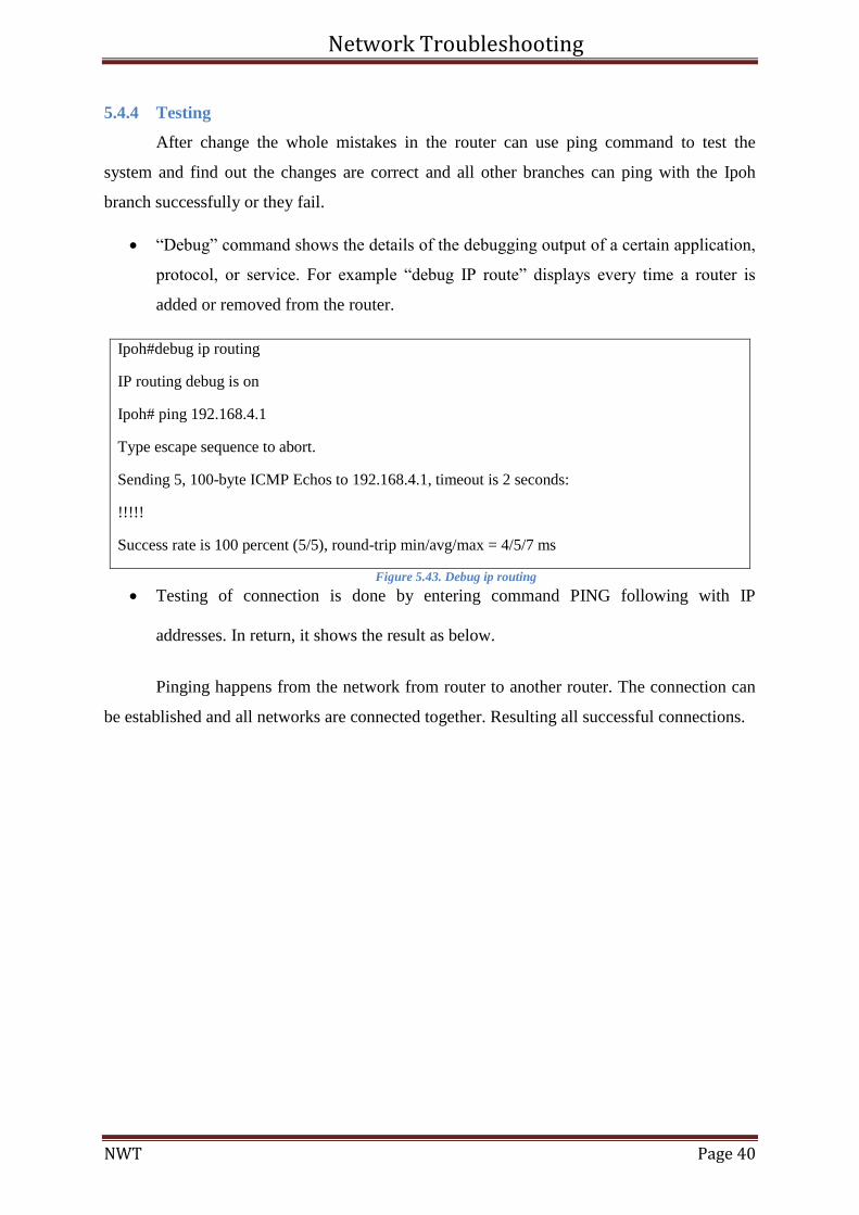
“Debug” command shows the details of the debugging output of a certain application,
protocol, or service. For example “debug IP route” displays every time a router is
added or removed from the router.
Ipoh#debug ip routing
IP routing debug is on
Ipoh# ping 192.168.4.1
Type escape sequence to abort.
Sending 5, 100-byte ICMP Echos to 192.168.4.1, timeout is 2 seconds:
!!!!!
Success rate is 100 percent (5/5), round-trip min/avg/max = 4/5/7 ms
Figure 5.43. Debug ip routing
Testing of connection is done by entering command PING following with IP
addresses. In return, it shows the result as below.
Pinging happens from the network from router to another router. The connection can
be established and all networks are connected together. Resulting all successful connections.
Network Troubleshooting
NWT Page 41
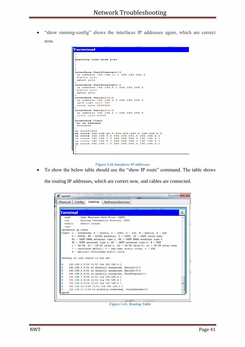
“show running-config” shows the interfaces IP addresses again, which are correct
now.
Figure 5.44 Interfaces IP addresses
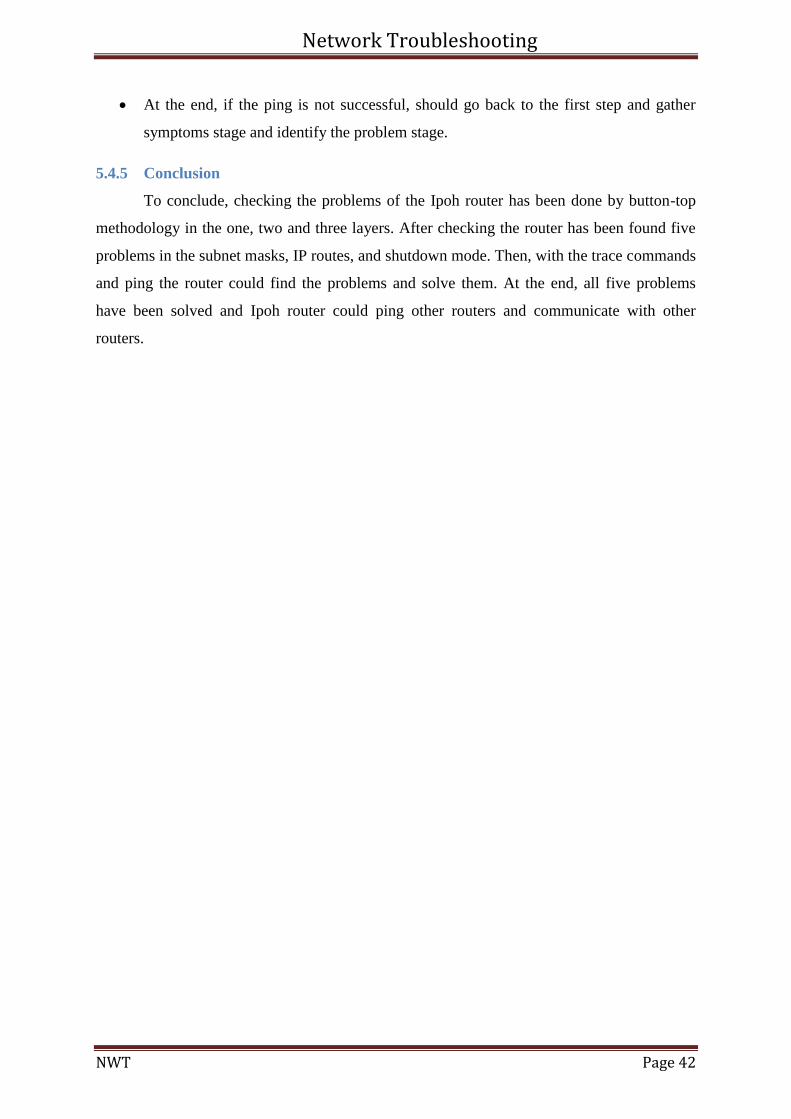
To show the below table should use the “show IP route” command. The table shows
the routing IP addresses, which are correct now, and cables are connected.
Figure 5.45. Routing Table
Network Troubleshooting
NWT Page 42
At the end, if the ping is not successful, should go back to the first step and gather
symptoms stage and identify the problem stage.
5.4.5 Conclusion
To conclude, checking the problems of the Ipoh router has been done by button-top
methodology in the one, two and three layers. After checking the router has been found five
problems in the subnet masks, IP routes, and shutdown mode. Then, with the trace commands
and ping the router could find the problems and solve them. At the end, all five problems
have been solved and Ipoh router could ping other routers and communicate with other
routers.
Network Troubleshooting
NWT Page 43
6 Section B
6.1 Chapter A VLSM
The abbreviation of VLSM is variable length subnet mask. It helps the network admin
to adjust the number of subnets and addresses on the basis of the requirement on the same
network. For few networks, it utilize longer masks while in some more hosts with shorter
masks. For example, 255.255.255.252 is suitable for point to point link as it allows to make
two hosts in each subnet. Likewise, 255.255.255.192 is suitable for LAN because it makes 62
hosts for each subnet. Because of the LAN subnet masks, it will not allow to make enough
hosts and regarding point to point link subnet masks, it will waste a lot of the hosts. In this
situation, it is sufficient to be using VLSM techniques in order to allow different subnet
masks on similar class address space. Each router is required different numbers of hosts. The
VLSM fits in the condition in the way that it allocates the subnets assigned to the IP address
and saves the available space without its wastage.
The characteristic of VLSM permits essentially designing and configuring a system
and having more productivity than FLSM. Diverse system frameworks and administrations
are utilizing VLSM which are open most brief way initially, upgraded inside gateway routing
protocol, border gateway protocol and moderate framework to halfway framework
convention. (Techopedia.com, 2011)
The routers and their IP addresses are below:
HQ (70 hosts required) 192.168.1.0 /25
Seremban (13 hosts required) 192.168.1.160 /28
Penang (40 hosts required) 192.168.1.192 /27
Ipoh (17 hosts required) 192.168.1.128 /28
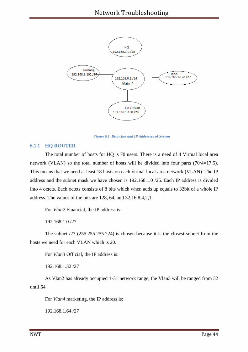
This is the design of the VLSM that divides one huge IP network class C to 4
different routers. The names of the routers are HQ, Seremban, Penang and Ipoh. Each branch
has its own host’s requirements. HQ has four departments which are Financial, official,
marketing and seller. On Ipoh, we are having one VLAN and the IP address of it is
192.168.1.128 /27. The following figure shows the routers with their respective IP addresses.
Network Troubleshooting
NWT Page 44
Figure 6.1. Branches and IP Addresses of System
6.1.1 HQ ROUTER
The total number of hosts for HQ is 70 users. There is a need of 4 Virtual local area
network (VLAN) so the total number of hosts will be divided into four parts (70/4=17.5).
This means that we need at least 18 hosts on each virtual local area network (VLAN). The IP
address and the subnet mask we have chosen is 192.168.1.0 /25. Each IP address is divided
into 4 octets. Each octets consists of 8 bits which when adds up equals to 32bit of a whole IP
address. The values of the bits are 128, 64, and 32,16,8,4,2,1.
For Vlan2 Financial, the IP address is:
192.168.1.0 /27
The subnet /27 (255.255.255.224) is chosen because it is the closest subnet from the
hosts we need for each VLAN which is 20.
For Vlan3 Official, the IP address is:
192.168.1.32 /27
As Vlan2 has already occupied 1-31 network range, the Vlan3 will be ranged from 32
until 64
For Vlan4 marketing, the IP address is:
192.168.1.64 /27
Network Troubleshooting
NWT Page 45
As Vlan3 has already occupied 33-63 network range, the Vlan3 will be ranged from
64 until 96
For Vlan5 Server, the IP address is:
192.168.1.96 /27
As Vlan4 has already occupied 65-95 network range, the Vlan5 will be ranged from
96 until 128
6.1.2 Penang Router
The router Penang needs to have 40 hosts and it is further divided into 2 VLANs. For
each network within Penang, the hosts are divided into 20 each. So, the subnet borrowed 3
bits from subnet mask and the remaining 5 is left with the hosts. The number of hosts per
network on Penang is then equals to 25
= 32.
The IP address of Fa0/0.2 for Penang network is
192.168.1.192 /27
For the next IP address of Fa0/0.3 for Penang network, the next range of 32bits will
be added to the IP address
192.168.1.225/27
6.1.3 Justification and Critical Thinking VLSM
Classless and Classful routing Protocols
Before you can deploy a VLSM design created on paper, you must first use a routing
protocol that supports VLSM. To support VLSM, the routing protocol must advertise the
mask along with each subnet. Without mask information, the router receiving the update
would be confused. To effectively support VLSM, the routing protocol needs to advertise the
correct mask along with each subnet, so the receiving router knows the exact subnet that is
being advertised.
Network Troubleshooting
NWT Page 46
Routing
Protocol
Is it
classless?
Sends Mask in
Updates
Supports
VLSM
Supports manual
route
summarization
RIP-1 No No No No
IGRP No No No No
RIP-2 Yes Yes Yes Yes
EIGRP Yes Yes Yes Yes
OSPF Yes Yes Yes Yes
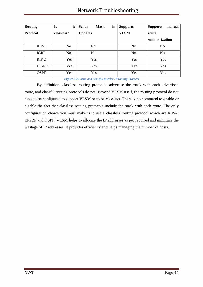
Figure 6.2.Classe and Classful interior IP routing Protocol
By definition, classless routing protocols advertise the mask with each advertised
route, and classful routing protocols do not. Beyond VLSM itself, the routing protocol do not
have to be configured to support VLSM or to be classless. There is no command to enable or
disable the fact that classless routing protocols include the mask with each route. The only
configuration choice you must make is to use a classless routing protocol which are RIP-2,
EIGRP and OSPF. VLSM helps to allocate the IP addresses as per required and minimize the
wastage of IP addresses. It provides efficiency and helps managing the number of hosts.
Network Troubleshooting
NWT Page 47
6.2 Chapter B Network Address Translation (NAT)
It enables invalid IP networks to connect to the Internet. NAT runs on a network to
connect two private networks and the public Internet to each other, and translates the private
addresses of the internal network into public addresses. It is because; the private addresses
can never be routed on the internet, so they need to replace the IP address-port pair of an IP
packet with another IP address-port pair. NAT can be configured to present one address for
the whole network to the outside world. It causes of extra security by hiding the entire
internal network behind the private IP address (Cisco, 2004). NAT implements in the remote
access environment, and suggests the double functions of security and address protection.
These are private IP addresses:
Class A: 10.0.0.0 through 10.255.255.255
Class B: 172.16.0.0 through 172.31.255.255
Class C: 192.168.0.0 through 192.168.255.255
NAT is not just restricted to the public-to-private address translation, it translates
public-to-public and private-to-private addresses as well. In addition, Cisco IOS devices and
PIX/ASA firewalls support NAT. NAT can be implemented by these three methods (Anon.,
2011):
Static NAT: Executes a static one to one conversion between two addresses, or a port
of one address to a port of another address.
Dynamic NAT: Operates global addresses to dynamically translate the outbound
traffic of clients behind a NAT device.
Port Address Translation (PAT): Translates the outbound traffic of clients to
unique port numbers of a single global address. It is needed when the number of
internal users exceeds the valid global addresses.
Masquerading NAT: A NAT router has only one registered IP address in this type of
NAT. The NAT router records each internal client, who needs to communicate with
the Internet to a different port from the registered IP address. The router writes the
address request in this form x.x.x.x: y. Replies from the Internet involves the
originating port, and then the router knows which internal IP address needs to map the
reply (Anon., 2011).
Mainly, NAT permits a router to act as an agent between private and public network.
With this feature, only a single IP address is needed to present the whole group of computers
Network Troubleshooting
NWT Page 48
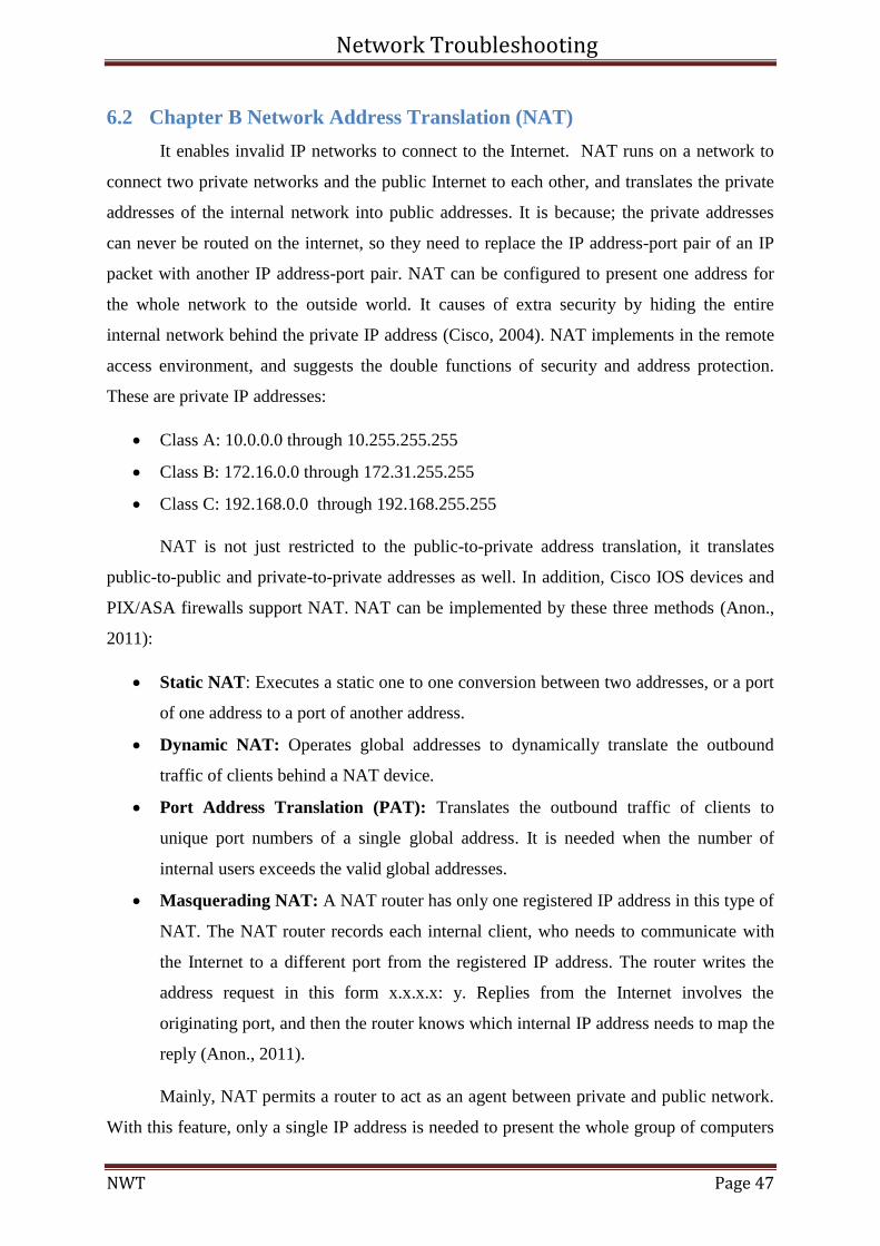
outside of their network. To configure the NAT, router needs at least one interface inside and
another one outside and a set of rules to translate the IP addresses in the packet headers.
Figure 6.3. NAT Design
6.2.1 Advantages of NAT
Saving public IP addresses. A client needs a valid IP address when it communicates
with the Internet, while invalid IP address sends traffic through the NAT, this
software translates the private address to the public address.
Hiding the internal network's IP addresses.
Supporting a wide range of clients
Supporting a large range of services with a few exceptions.
Consuming less computer resources and more capable than using SOCKS and
application proxy servers
The Universal Connections can run through NAT.
(Anon., 2011)
6.2.2 Disadvantages of NAT
Providing minimum logging services
Needs IP forwarding before using the NAT to make the Internet connection
It can break convinced applications, or make them more difficult to run
(Anon., 2011)
Network Troubleshooting
NWT Page 49
6.2.3 Network Addresses Translation (NAT) Configuration
For the current project NAT masquerading have been used. The NAT router modifies
the source port number to a port on the router’s outside interface. Thus, replies go to the same
port, which are NAT router knows the internal ports to send the replies. This kind of NAT
helps to control access to the system and servers. Configuring the NAT have done in the
Head Quarter building and Penang branch. Both buildings are connected to the Internet
(Cisco, 2004).
To configure NAT to the router and create NAT router first should determine the
inside and outside IP NAT for the router. The process is in the below for Head Quarter and
Penang branch. However, the first step of NAT configure is, configuring the all router
interfaces and PCs with the following commands. For instance, below table has been shown
the configuration of serial 0/0/0. The two below tables are as an example for both branches.
H.Q>enable (Move to privileged mode)
H.Q# configure terminal (Go to global configuration mode to make global parameter changes in the
router)
H.Q(config)#interface serial0/0/0 (Go to the 0/0/0 serial to add the IP address)
H.Q(config-if)#ip address192.168.1.178 255.255.255.0 (add the IP address)
H.Q(config-if)#no shutdown
Figure 6.4. IP configuration of HQ
Penang>enable (Move to privileged mode)
Penang# configure terminal (Go to global configuration mode to make global parameter changes in
the router)
Penang(config)#interface fastethernet0/0 (Go to the 0/0/0 serial to add the IP address)
Penang(config-if)#ip address192.168.1.186 255.255.255.0 (add the IP address)
Penang(config-if)#no shutdown
Figure 6.5. IP Configuration of Penang
For other interfaces, should continue these steps to configure the IP addresses of the
whole fast Ethernets and serials of both router.
The next step is, configuring the NAT, which should define the inside and outside
NAT in the router. To determine the kind of NAT should go into the serial and type “IP NAT
inside” command. Interfaces should mark as inside or outside, because only marked
interfaces will be subject to translation (Cisco, 2004).
Network Troubleshooting
NWT Page 50
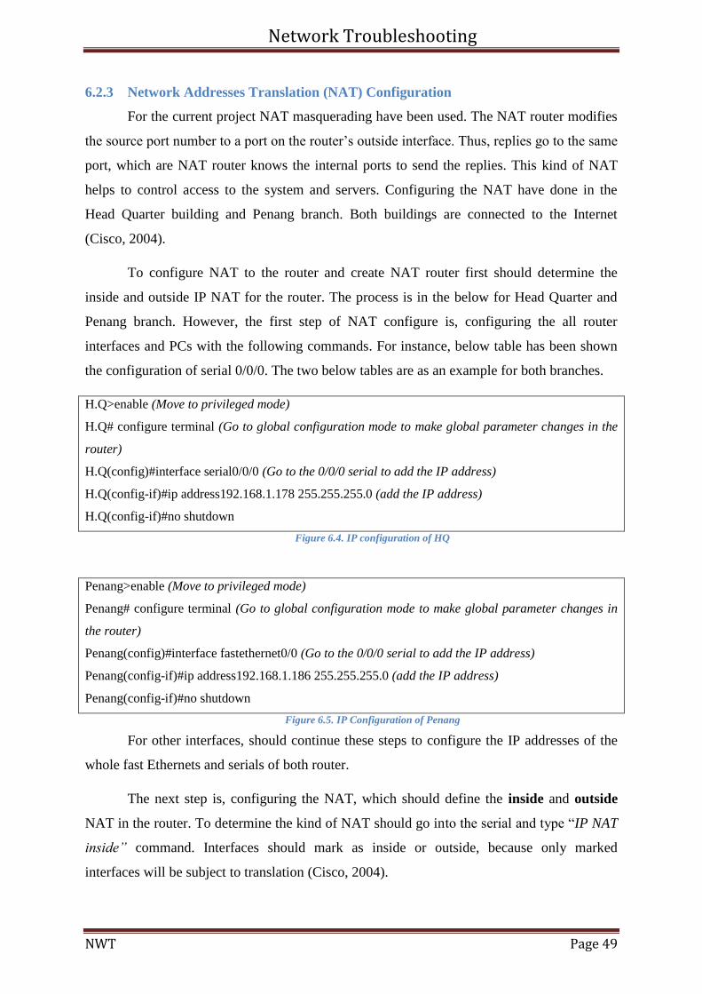
In the Head Quarter Serial 0/2/0 is outside NAT interface, and FastEthernet0/1, 0/1.2,
0/1.3, 0/1.4, 0/1.5, and Serial 0/0/0 are inside NAT interfaces.
H.Q(config)#interface serial0/0/0 (Go to the particular serial)
H.Q(config-if)#ip nat inside (Determine the inside NAT)
H.Q(config)#interface serial0/2/0
H.Q(config-if)#ip nat outside (Determine the outside NAT)
Figure 6.6. Define INSIDE and OUTSIDE NAT
Figure 6.7. Inside and Outside NAT
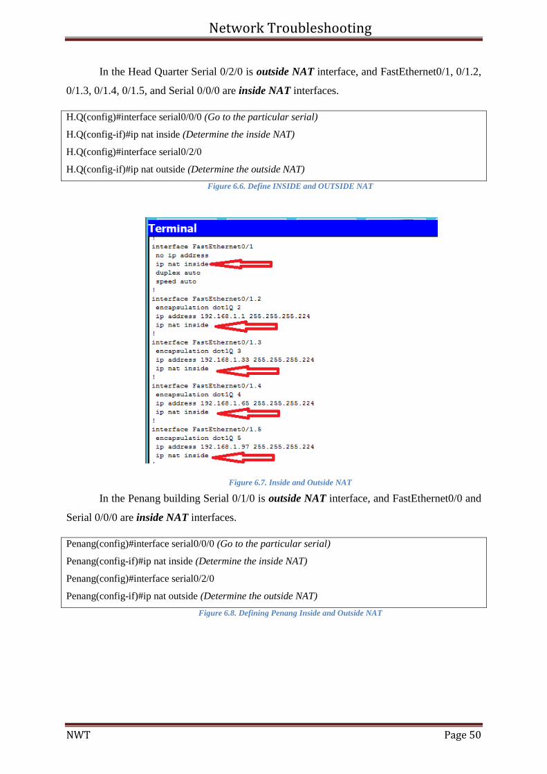
In the Penang building Serial 0/1/0 is outside NAT interface, and FastEthernet0/0 and
Serial 0/0/0 are inside NAT interfaces.
Penang(config)#interface serial0/0/0 (Go to the particular serial)
Penang(config-if)#ip nat inside (Determine the inside NAT)
Penang(config)#interface serial0/2/0
Penang(config-if)#ip nat outside (Determine the outside NAT)
Figure 6.8. Defining Penang Inside and Outside NAT
Network Troubleshooting
NWT Page 51
Figure 6.9. Penang Inside and Outside NAT
Step three is after defining the inside and outside NAT, which should create a
standard access-list to match the “internal” IP addresses. In this case internal network is serial
0/0/0 (192.168.1.0/30) in the HQ and serial 0/0/0 (0.0.0.0/26). For example:
H.Q(config-if)#ip access-list standard NAT (Controls the transmission of packets on an interface)
H.Q(config-std-nac1)#permit 192.168.1.0 0.0.0.127
H.Q(config-std-nac1)#permit 192.168.1.160 0.0.0.3 (Public addresses should translate to these
private addresses) Figure 6.10. Configure Access List of HQ
Penang(config-if)#ip access-list standard NAT
Penang(config-std-nac1)#permit 0.0.0.0 255.255.255.192
Penang(config-std-nac1)#permit 0.0.0.0 255.255.255.224 (Public addresses should translate to these
private addresses)
Figure 6.11. Configure Access list of Penang
To define a pool of HQ in the NAT should follow the below steps, which is between
inside host addressed from 192.168.1.0 or 192.168.1.160 nets to the globally unique
20.20.20.1/30 network. The name of the pool will be same as the name of the router, which is
HQ. For instance the process is in the following.
H.Q(confih)#ip nat inside source list 7 pool HQ
H.Q(config)#ip nat pool HQ 20.20.20.1 20.20.20.1 netmask 255.255.255.252 (The range of public
addresses, which are packets come from these addresses)
Figure 6.12. Defining the Pool of HQ
To define a pool of Penang should follow the above steps in the NAT. The inside host
addressed is 0.0.0.0 net to the globally unique 30.30.30.1/30 network. The name of the pool
will be same as the name of the router, which is Penang. For instance the process is in the
following.
Network Troubleshooting
NWT Page 52
Penang(confih)#ip nat inside source list 7 pool Penang
Penang(config)#ip nat pool HQ 30.30.30.1 30.30.30.1 netmask 0.0.0.3 (The range of public
addresses, which are packets come from these addresses)
Figure 6.13. Defining the Pool of Penang
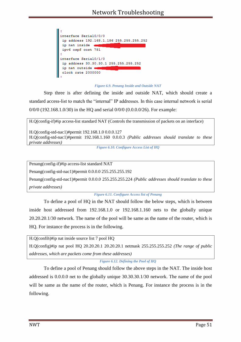
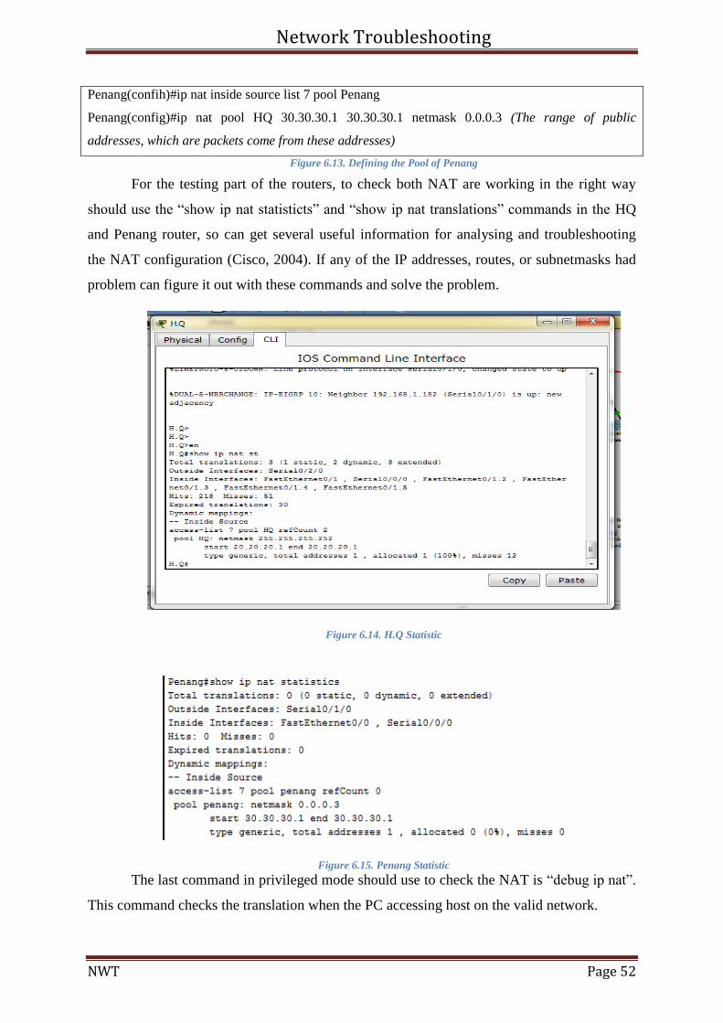
For the testing part of the routers, to check both NAT are working in the right way
should use the “show ip nat statisticts” and “show ip nat translations” commands in the HQ
and Penang router, so can get several useful information for analysing and troubleshooting
the NAT configuration (Cisco, 2004). If any of the IP addresses, routes, or subnetmasks had
problem can figure it out with these commands and solve the problem.
Figure 6.14. H.Q Statistic
Figure 6.15. Penang Statistic
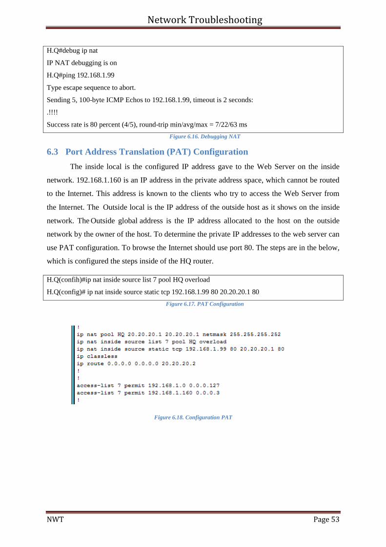
The last command in privileged mode should use to check the NAT is “debug ip nat”.
This command checks the translation when the PC accessing host on the valid network.
Network Troubleshooting
NWT Page 53
H.Q#debug ip nat
IP NAT debugging is on
H.Q#ping 192.168.1.99
Type escape sequence to abort.
Sending 5, 100-byte ICMP Echos to 192.168.1.99, timeout is 2 seconds:
.!!!!
Success rate is 80 percent (4/5), round-trip min/avg/max = 7/22/63 ms
Figure 6.16. Debugging NAT
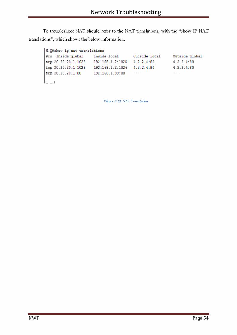
6.3 Port Address Translation (PAT) Configuration
The inside local is the configured IP address gave to the Web Server on the inside
network. 192.168.1.160 is an IP address in the private address space, which cannot be routed
to the Internet. This address is known to the clients who try to access the Web Server from
the Internet. The Outside local is the IP address of the outside host as it shows on the inside
network. The Outside global address is the IP address allocated to the host on the outside
network by the owner of the host. To determine the private IP addresses to the web server can
use PAT configuration. To browse the Internet should use port 80. The steps are in the below,
which is configured the steps inside of the HQ router.
H.Q(confih)#ip nat inside source list 7 pool HQ overload
H.Q(config)# ip nat inside source static tcp 192.168.1.99 80 20.20.20.1 80
Figure 6.17. PAT Configuration
Figure 6.18. Configuration PAT
Network Troubleshooting
NWT Page 54
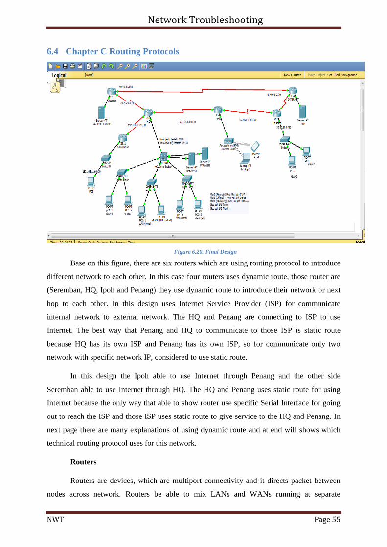
To troubleshoot NAT should refer to the NAT translations, with the “show IP NAT
translations”, which shows the below information.
Figure 6.19. NAT Translation
Network Troubleshooting
NWT Page 55
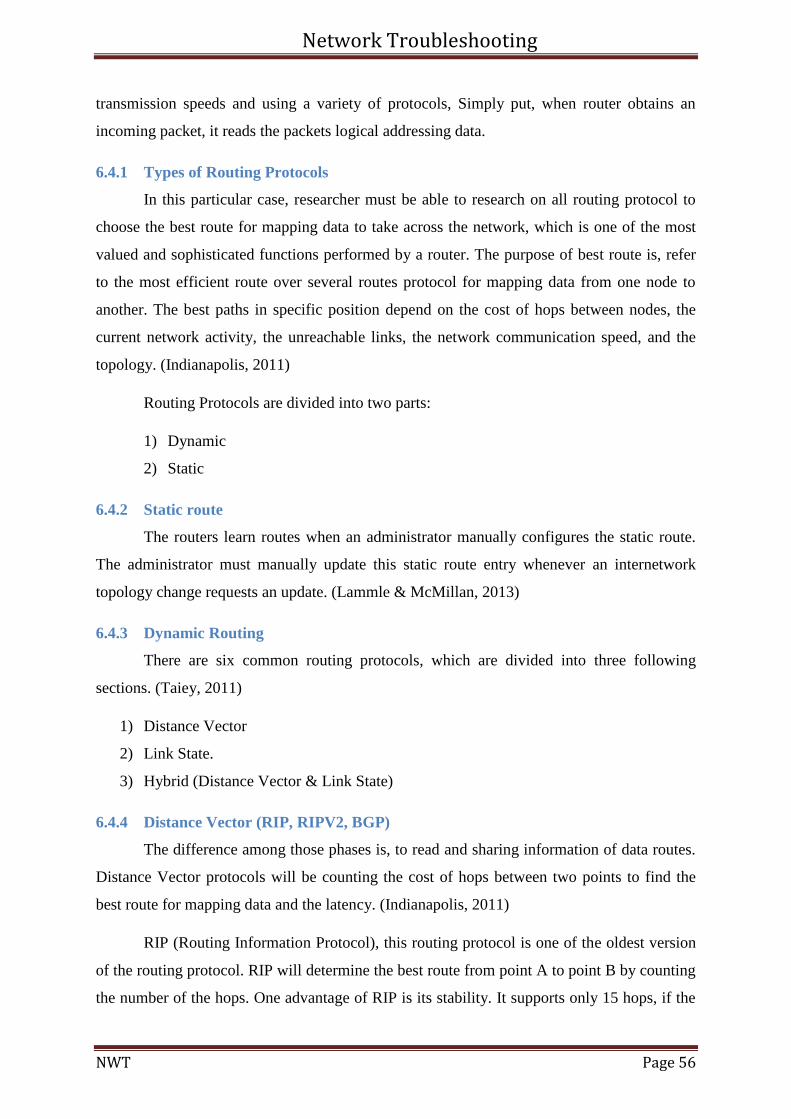
6.4 Chapter C Routing Protocols
Figure 6.20. Final Design
Base on this figure, there are six routers which are using routing protocol to introduce
different network to each other. In this case four routers uses dynamic route, those router are
(Seremban, HQ, Ipoh and Penang) they use dynamic route to introduce their network or next
hop to each other. In this design uses Internet Service Provider (ISP) for communicate
internal network to external network. The HQ and Penang are connecting to ISP to use
Internet. The best way that Penang and HQ to communicate to those ISP is static route
because HQ has its own ISP and Penang has its own ISP, so for communicate only two
network with specific network IP, considered to use static route.
In this design the Ipoh able to use Internet through Penang and the other side
Seremban able to use Internet through HQ. The HQ and Penang uses static route for using
Internet because the only way that able to show router use specific Serial Interface for going
out to reach the ISP and those ISP uses static route to give service to the HQ and Penang. In
next page there are many explanations of using dynamic route and at end will shows which
technical routing protocol uses for this network.
Routers
Routers are devices, which are multiport connectivity and it directs packet between
nodes across network. Routers be able to mix LANs and WANs running at separate
Network Troubleshooting
NWT Page 56
transmission speeds and using a variety of protocols, Simply put, when router obtains an
incoming packet, it reads the packets logical addressing data.
6.4.1 Types of Routing Protocols
In this particular case, researcher must be able to research on all routing protocol to
choose the best route for mapping data to take across the network, which is one of the most
valued and sophisticated functions performed by a router. The purpose of best route is, refer
to the most efficient route over several routes protocol for mapping data from one node to
another. The best paths in specific position depend on the cost of hops between nodes, the
current network activity, the unreachable links, the network communication speed, and the
topology. (Indianapolis, 2011)
Routing Protocols are divided into two parts:
1) Dynamic
2) Static
6.4.2 Static route
The routers learn routes when an administrator manually configures the static route.
The administrator must manually update this static route entry whenever an internetwork
topology change requests an update. (Lammle & McMillan, 2013)
6.4.3 Dynamic Routing
There are six common routing protocols, which are divided into three following
sections. (Taiey, 2011)
1) Distance Vector
2) Link State.
3) Hybrid (Distance Vector & Link State)
6.4.4 Distance Vector (RIP, RIPV2, BGP)
The difference among those phases is, to read and sharing information of data routes.
Distance Vector protocols will be counting the cost of hops between two points to find the
best route for mapping data and the latency. (Indianapolis, 2011)
RIP (Routing Information Protocol), this routing protocol is one of the oldest version
of the routing protocol. RIP will determine the best route from point A to point B by counting
the number of the hops. One advantage of RIP is its stability. It supports only 15 hops, if the
Network Troubleshooting
NWT Page 57
number of hops in a route exceeds 15, the network destination is considered unreachable. RIP
version 2 supports same as RIP V1, but the difference are: (Lammle & McMillan, 2013)
1) Less broadcast
2) More secure than RIP V1
BGP communicate unlike RIP. This routing protocol uses specific message, which
travels between routers over TCP sessions. This routing protocol of choice for Internet traffic
and it is used by border.
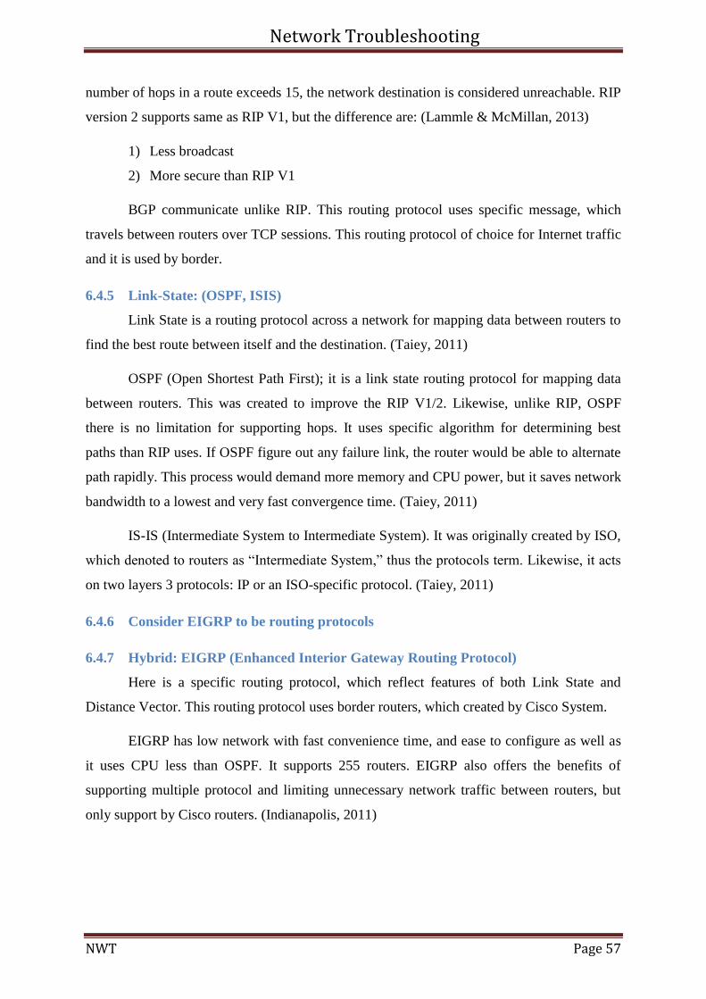
6.4.5 Link-State: (OSPF, ISIS)
Link State is a routing protocol across a network for mapping data between routers to
find the best route between itself and the destination. (Taiey, 2011)
OSPF (Open Shortest Path First); it is a link state routing protocol for mapping data
between routers. This was created to improve the RIP V1/2. Likewise, unlike RIP, OSPF
there is no limitation for supporting hops. It uses specific algorithm for determining best
paths than RIP uses. If OSPF figure out any failure link, the router would be able to alternate
path rapidly. This process would demand more memory and CPU power, but it saves network
bandwidth to a lowest and very fast convergence time. (Taiey, 2011)
IS-IS (Intermediate System to Intermediate System). It was originally created by ISO,
which denoted to routers as “Intermediate System,” thus the protocols term. Likewise, it acts
on two layers 3 protocols: IP or an ISO-specific protocol. (Taiey, 2011)
6.4.6 Consider EIGRP to be routing protocols
6.4.7 Hybrid: EIGRP (Enhanced Interior Gateway Routing Protocol)
Here is a specific routing protocol, which reflect features of both Link State and
Distance Vector. This routing protocol uses border routers, which created by Cisco System.
EIGRP has low network with fast convenience time, and ease to configure as well as
it uses CPU less than OSPF. It supports 255 routers. EIGRP also offers the benefits of
supporting multiple protocol and limiting unnecessary network traffic between routers, but
only support by Cisco routers. (Indianapolis, 2011)
Network Troubleshooting
NWT Page 58
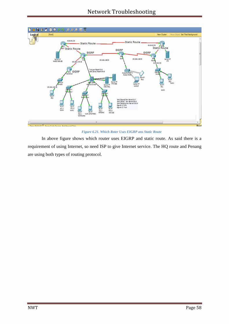
Figure 6.21. Which Roter Uses EIGRP ans Static Route
In above figure shows which router uses EIGRP and static route. As said there is a
requirement of using Internet, so need ISP to give Internet service. The HQ route and Penang
are using both types of routing protocol.

Network Troubleshooting
NWT Page 59
6.4.8 Justify & critical thinking of routing protocol
EIGRP uses four different table to build and maintain a sense of the network
topology. To avoid loops EIGRP uses Diffusing Update Algorithm (DUAL) algorithm. This
algorithm developed of the Distance Vector and containing loop-free warranty, delay
processing operations, finite time calculations to find shortest path. In addition, it uses
(DUAL) to perform shortest path routing. (Lammle & McMillan, 2013)
EIGRP utilize Hello protocol to determine neighbours and send updates when
topology changes occur. Legacy protocol of Internetwork Packet Exchange (IPX) and Apple
Talk traffic could be supported by EIGRP. EIGRP by default summarizes routes on the class-
full network boundaries. EIGRP has summarization routes in each interface. By this feature
network designer would be able to summarize their networks for maximum efficiency
without the constraints of specific borders or other topological designation. (Lammle &
McMillan, 2013)
Note: EIGRP uses the minimum bandwidth for counting the routing metrics and the
total delay to compute. There are two methods that determines the value of configuring the
interfaces of routers, those methods are; 1) bandwidth. 2) Delay metrics.
EIGRP uses the following formula to scale the bandwidth:
Bandwidth = (10000000/Bandwidth (i))*256
For scaling the delay EIGRP uses following formula:
Delay = Delay (i)*256
For scaling the total metrics the EIGRP uses following formula:
Metric = [K1 * bandwidth + (K2 * bandwidth) / (256 - load) + K3 * delay] * [K5 /
(reliability + K4)]
6.4.9 SUMMARIZATION
Summarization is divided into two parts;
1) Auto summarization
2) Manual summaries
Network Troubleshooting
NWT Page 60
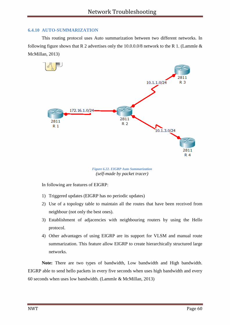
6.4.10 AUTO-SUMMARIZATION
This routing protocol uses Auto summarization between two different networks. In
following figure shows that R 2 advertises only the 10.0.0.0/8 network to the R 1. (Lammle &
McMillan, 2013)
Figure 6.22. EIGRP Auto Summarization
(self-made by packet tracer)
In following are features of EIGRP:
1) Triggered updates (EIGRP has no periodic updates)
2) Use of a topology table to maintain all the routes that have been received from
neighbour (not only the best ones).
3) Establishment of adjacencies with neighbouring routers by using the Hello
protocol.
4) Other advantages of using EIGRP are its support for VLSM and manual route
summarization. This feature allow EIGRP to create hierarchically structured large
networks.
Note: There are two types of bandwidth, Low bandwidth and High bandwidth.
EIGRP able to send hello packets in every five seconds when uses high bandwidth and every
60 seconds when uses low bandwidth. (Lammle & McMillan, 2013)
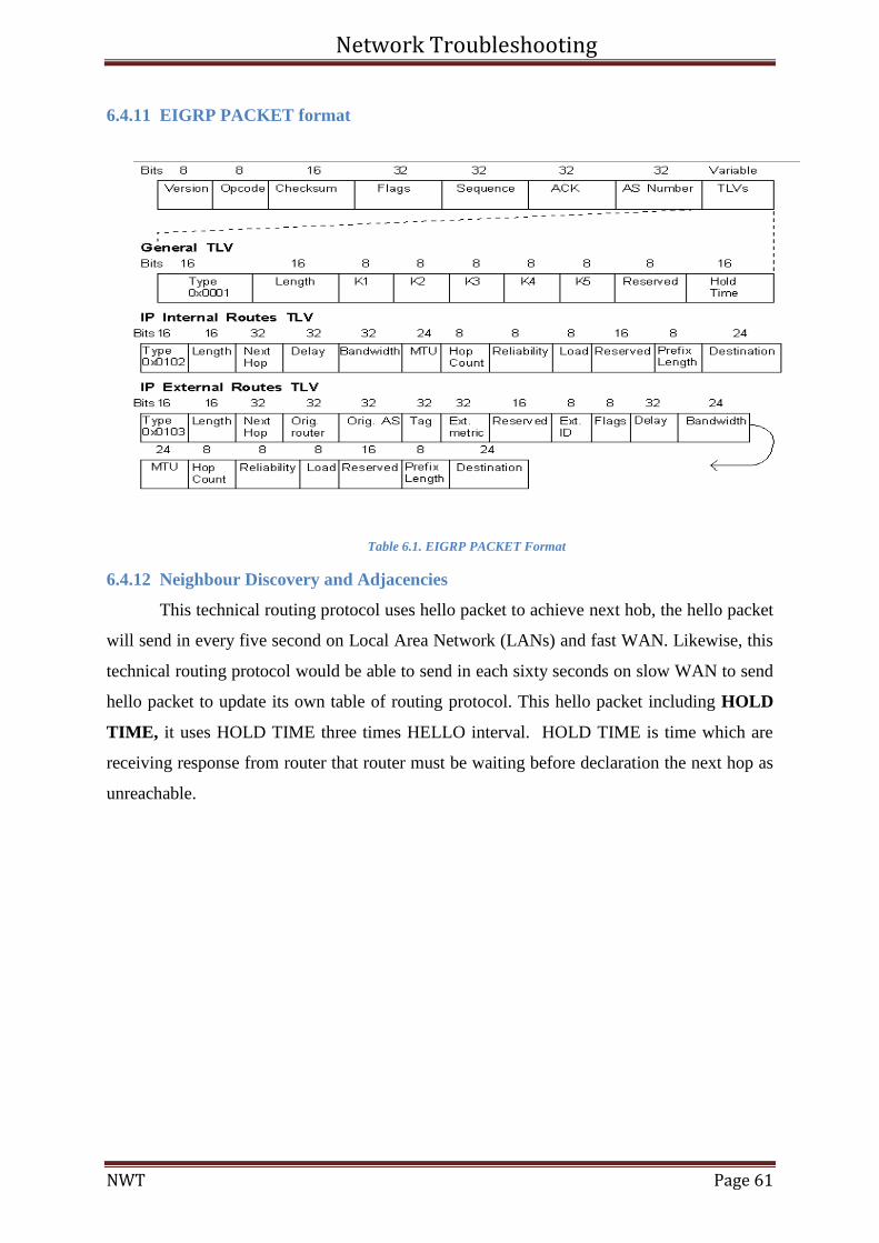
Network Troubleshooting
NWT Page 61
6.4.11 EIGRP PACKET format
Table 6.1. EIGRP PACKET Format
6.4.12 Neighbour Discovery and Adjacencies
This technical routing protocol uses hello packet to achieve next hob, the hello packet
will send in every five second on Local Area Network (LANs) and fast WAN. Likewise, this
technical routing protocol would be able to send in each sixty seconds on slow WAN to send
hello packet to update its own table of routing protocol. This hello packet including HOLD
TIME, it uses HOLD TIME three times HELLO interval. HOLD TIME is time which are
receiving response from router that router must be waiting before declaration the next hop as
unreachable.
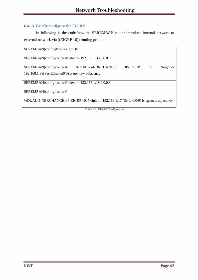
Network Troubleshooting
NWT Page 62
6.4.13 Briefly configure the EIGRP
In following is the code how the SEREMBAN router introduce internal network to
external network via ((EIGRP 10)) routing protocol.
SEREMBAN(config)#route eigrp 10
SEREMBAN(config-router)#network 192.168.1.36 0.0.0.3
SEREMBAN(config-router)# %DUAL-5-NBRCHANGE: IP-EIGRP 10: Neighbor
192.168.1.38(FastEthernet0/0) is up: new adjacency
SEREMBAN(config-router)#network 192.168.1.18 0.0.0.3
SEREMBAN(config-router)#
%DUAL-5-NBRCHANGE: IP-EIGRP 10: Neighbor 192.168.1.17 (Serial0/0/0) is up: new adjacency
Table 6.2. EIGRP Configuration
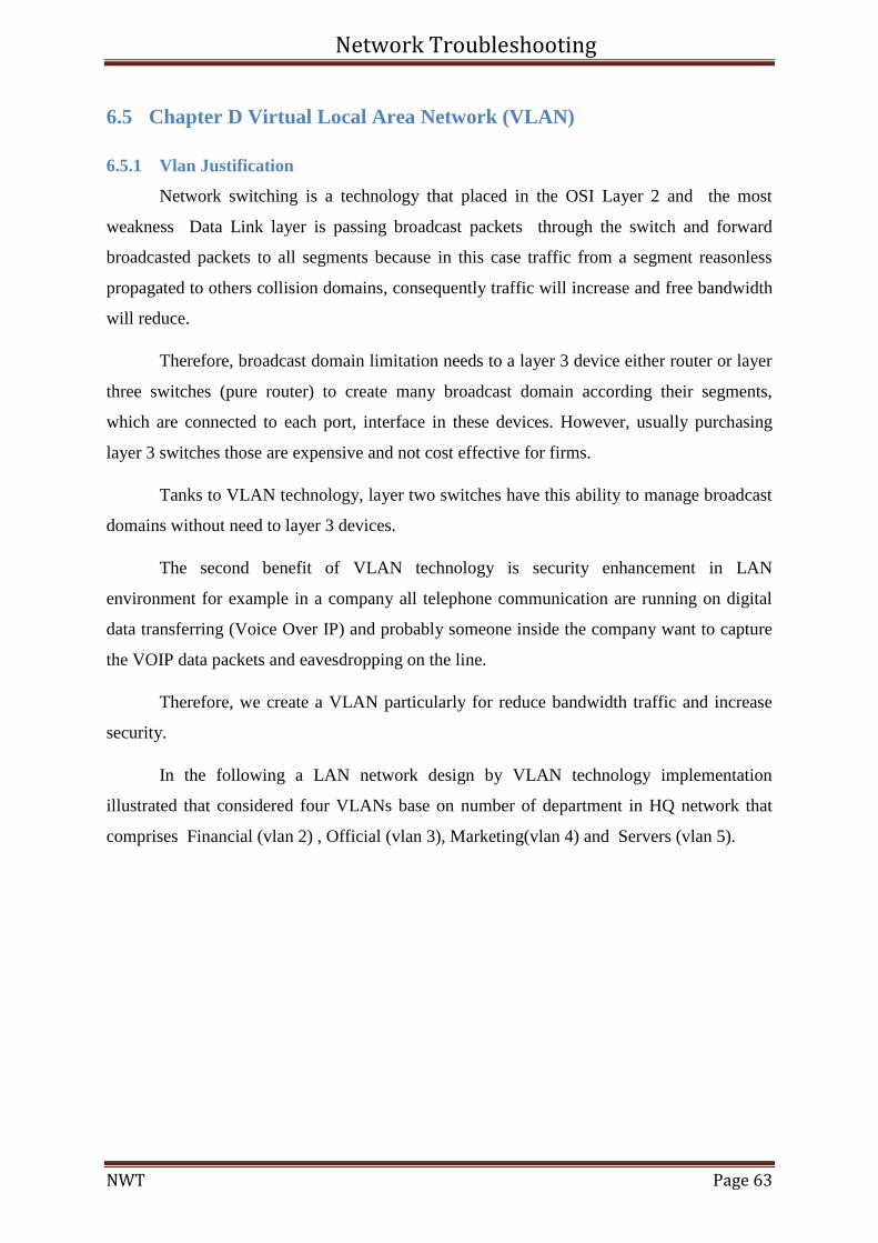
Network Troubleshooting
NWT Page 63
6.5 Chapter D Virtual Local Area Network (VLAN)
6.5.1 Vlan Justification
Network switching is a technology that placed in the OSI Layer 2 and the most
weakness Data Link layer is passing broadcast packets through the switch and forward
broadcasted packets to all segments because in this case traffic from a segment reasonless
propagated to others collision domains, consequently traffic will increase and free bandwidth
will reduce.
Therefore, broadcast domain limitation needs to a layer 3 device either router or layer
three switches (pure router) to create many broadcast domain according their segments,
which are connected to each port, interface in these devices. However, usually purchasing
layer 3 switches those are expensive and not cost effective for firms.
Tanks to VLAN technology, layer two switches have this ability to manage broadcast
domains without need to layer 3 devices.
The second benefit of VLAN technology is security enhancement in LAN
environment for example in a company all telephone communication are running on digital
data transferring (Voice Over IP) and probably someone inside the company want to capture
the VOIP data packets and eavesdropping on the line.
Therefore, we create a VLAN particularly for reduce bandwidth traffic and increase
security.
In the following a LAN network design by VLAN technology implementation
illustrated that considered four VLANs base on number of department in HQ network that
comprises Financial (vlan 2) , Official (vlan 3), Marketing(vlan 4) and Servers (vlan 5).
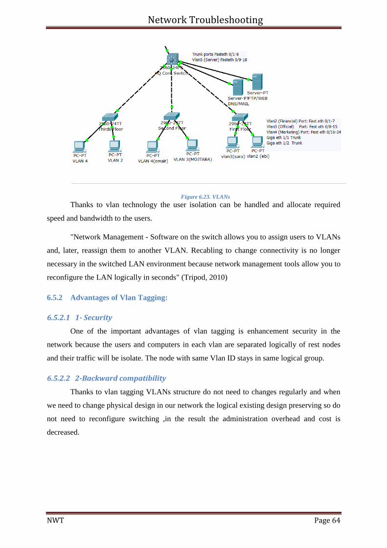
Network Troubleshooting
NWT Page 64
Figure 6.23. VLANs
Thanks to vlan technology the user isolation can be handled and allocate required
speed and bandwidth to the users.
"Network Management - Software on the switch allows you to assign users to VLANs
and, later, reassign them to another VLAN. Recabling to change connectivity is no longer
necessary in the switched LAN environment because network management tools allow you to
reconfigure the LAN logically in seconds" (Tripod, 2010)
6.5.2 Advantages of Vlan Tagging:
6.5.2.1 1- Security
One of the important advantages of vlan tagging is enhancement security in the
network because the users and computers in each vlan are separated logically of rest nodes
and their traffic will be isolate. The node with same Vlan ID stays in same logical group.
6.5.2.2 2-Backward compatibility
Thanks to vlan tagging VLANs structure do not need to changes regularly and when
we need to change physical design in our network the logical existing design preserving so do
not need to reconfigure switching ,in the result the administration overhead and cost is
decreased.
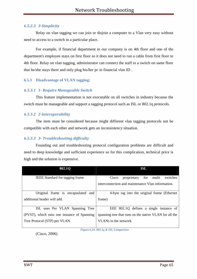
Network Troubleshooting
NWT Page 65
6.5.2.3 3-Simplicity
Relay on vlan tagging we can join or disjoin a computer to a Vlan very easy without
need to access to a switch in a particular place.
For example, if financial department in our company is on 4th floor and one of the
department's employee stays on first floor so it does not need to run a cable from first floor to
4th floor. Relay on vlan tagging, administrator can connect the staff to a switch on same floor
that he/she stays there and only plug his/her pc in financial vlan ID .
6.5.3 Disadvantage of VLAN tagging:
6.5.3.1 1- Require Manageable Switch
This feature implementation is not executable on all switches in industry because the
switch must be manageable and support a tagging protocol such as ISL or 802.1q protocols.
6.5.3.2 2-interoperability
The item must be considered because might different vlan tagging protocols not be
compatible with each other and network gets an inconsistency situation.
6.5.3.3 3- Troubleshooting difficulty
Founding out and troubleshooting protocol configuration problems are difficult and
need to deep knowledge and sufficient experience so for this complication, technical price is
high and the solution is expensive.
802.1Q ISL
IEEE Standard for tagging frame Cisco proprietary for multi switches
interconnection and maintenance Vlan information.
Original frame is encapsulated and
additional header will add.
4-byte tag into the original frame (Ethernet
frame)
ISL uses Per VLAN Spanning Tree
(PVST), which runs one instance of Spanning
Tree Protocol (STP) per VLAN.
EEE 802.1Q defines a single instance of
spanning tree that runs on the native VLAN for all the
VLANs in the network.
Figure 6.24. 802.1q & ISL Comparison
(Cisco, 2006)
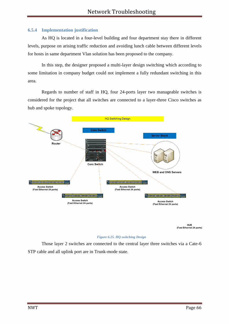
Network Troubleshooting
NWT Page 66
6.5.4 Implementation justification
As HQ is located in a four-level building and four department stay there in different
levels, purpose on arising traffic reduction and avoiding lunch cable between different levels
for hosts in same department Vlan solution has been proposed to the company.
In this step, the designer proposed a multi-layer design switching which according to
some limitation in company budget could not implement a fully redundant switching in this
area.
Regards to number of staff in HQ, four 24-ports layer two manageable switches is
considered for the project that all switches are connected to a layer-three Cisco switches as
hub and spoke topology.
Figure 6.25. HQ switching Design
Those layer 2 switches are connected to the central layer three switches via a Cate-6
STP cable and all uplink port are in Trunk-mode state.
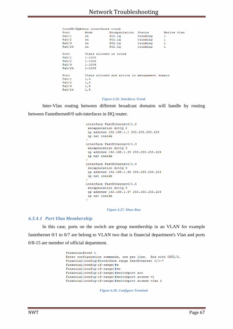
Network Troubleshooting
NWT Page 67
Figure 6.26. Interfaces Trunk
Inter-Vlan routing between different broadcast domains will handle by routing
between Fastethernet0/0 sub-interfaces in HQ router.
Figure 6.27. Show Run
6.5.4.1 Port Vlan Membership
In this case, ports on the switch are group membership in an VLAN for example
fastethernet 0/1 to 0/7 are belong to VLAN two that is financial department's Vlan and ports
0/8-15 are member of official department.
Figure 6.28. Configure Terminal
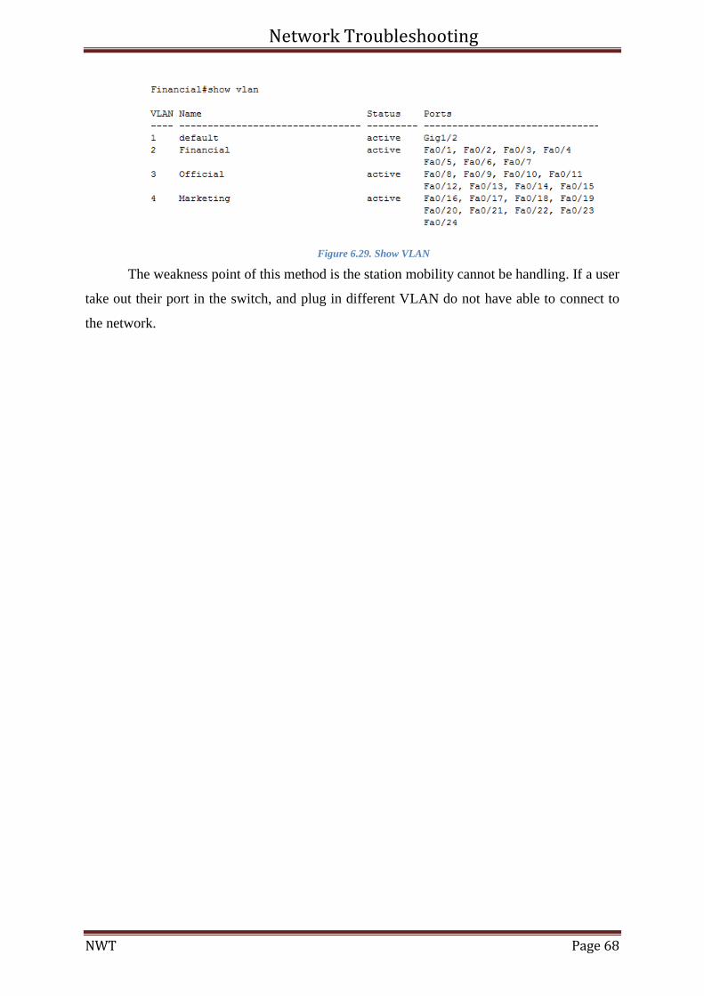
Network Troubleshooting
NWT Page 68
Figure 6.29. Show VLAN
The weakness point of this method is the station mobility cannot be handling. If a user
take out their port in the switch, and plug in different VLAN do not have able to connect to
the network.
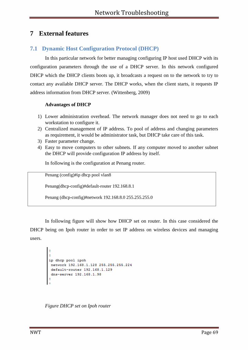
Network Troubleshooting
NWT Page 69
7 External features
7.1 Dynamic Host Configuration Protocol (DHCP)
In this particular network for better managing configuring IP host used DHCP with its
configuration parameters through the use of a DHCP server. In this network configured
DHCP which the DHCP clients boots up, it broadcasts a request on to the network to try to
contact any available DHCP server. The DHCP works, when the client starts, it requests IP
address information from DHCP server. (Wittenberg, 2009)
Advantages of DHCP
1) Lower administration overhead. The network manager does not need to go to each
workstation to configure it.
2) Centralized management of IP address. To pool of address and changing parameters
as requirement, it would be administrator task, but DHCP take care of this task.
3) Faster parameter change.
4) Easy to move computers to other subnets. If any computer moved to another subnet
the DHCP will provide configuration IP address by itself.
In following is the configuration at Penang router.
Penang (config)#ip dhcp pool vlan8
Penang(dhcp-config)#default-router 192.168.8.1
Penang (dhcp-config)#network 192.168.8.0 255.255.255.0
In following figure will show how DHCP set on router. In this case considered the
DHCP being on Ipoh router in order to set IP address on wireless devices and managing
users.
Figure DHCP set on Ipoh router
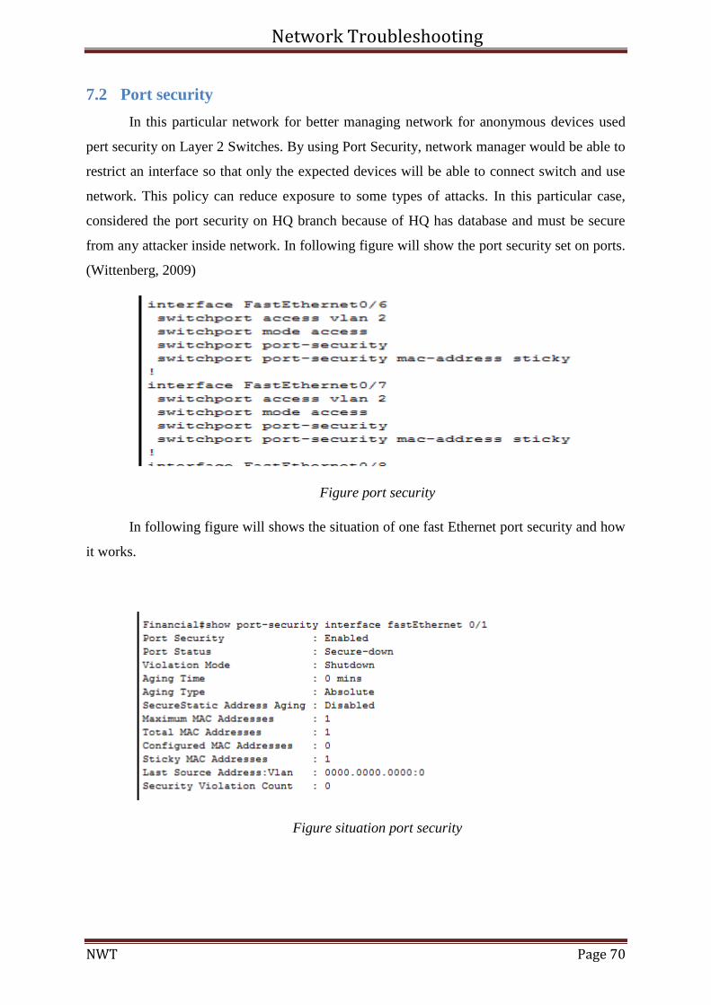
Network Troubleshooting
NWT Page 70
7.2 Port security
In this particular network for better managing network for anonymous devices used
pert security on Layer 2 Switches. By using Port Security, network manager would be able to
restrict an interface so that only the expected devices will be able to connect switch and use
network. This policy can reduce exposure to some types of attacks. In this particular case,
considered the port security on HQ branch because of HQ has database and must be secure
from any attacker inside network. In following figure will show the port security set on ports.
(Wittenberg, 2009)
Figure port security
In following figure will shows the situation of one fast Ethernet port security and how
it works.
Figure situation port security
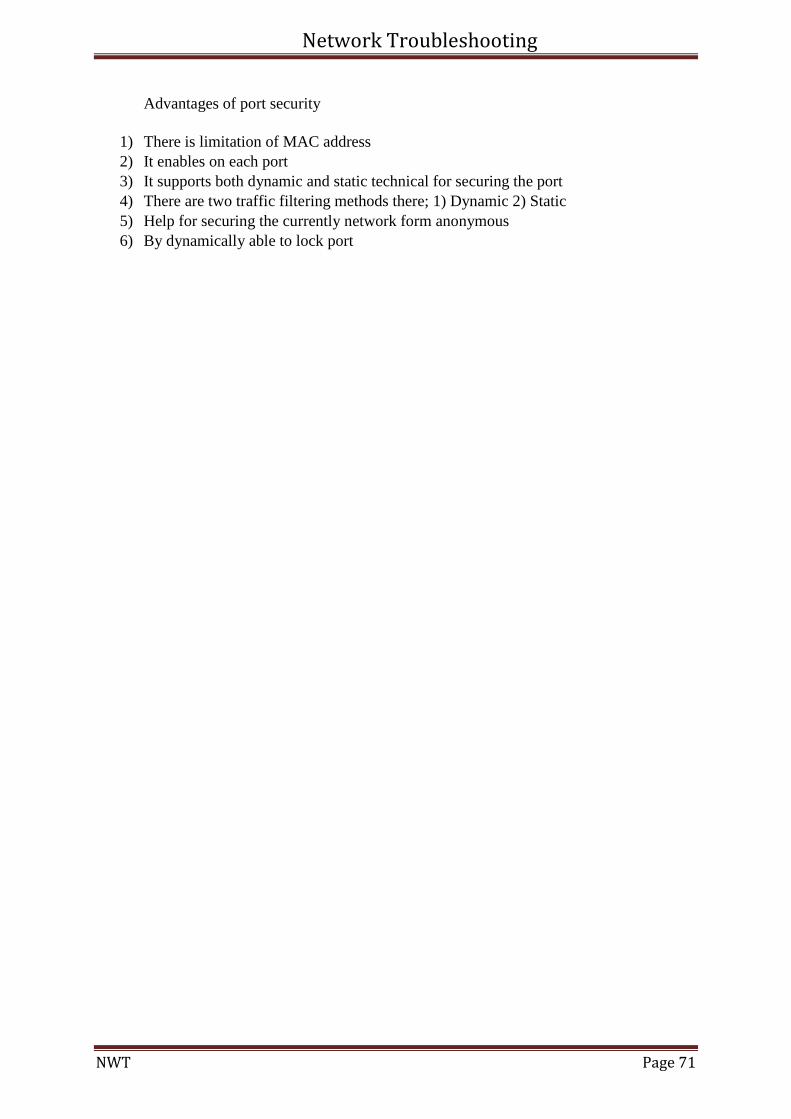
Network Troubleshooting
NWT Page 71
Advantages of port security
1) There is limitation of MAC address
2) It enables on each port
3) It supports both dynamic and static technical for securing the port
4) There are two traffic filtering methods there; 1) Dynamic 2) Static
5) Help for securing the currently network form anonymous
6) By dynamically able to lock port
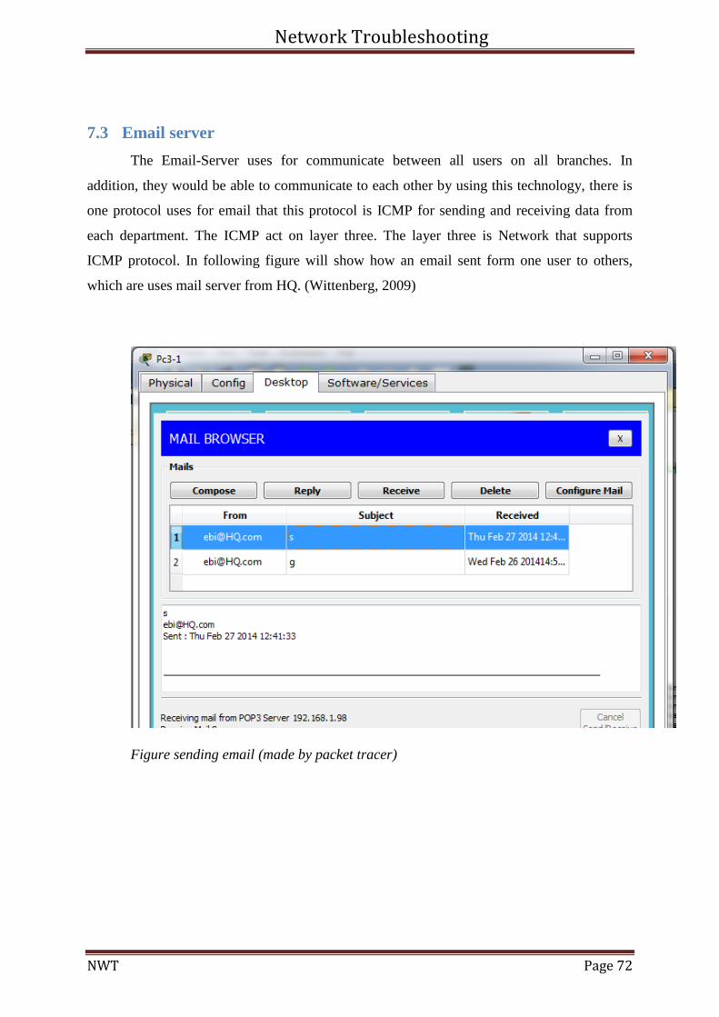
Network Troubleshooting
NWT Page 72
7.3 Email server
The Email-Server uses for communicate between all users on all branches. In
addition, they would be able to communicate to each other by using this technology, there is
one protocol uses for email that this protocol is ICMP for sending and receiving data from
each department. The ICMP act on layer three. The layer three is Network that supports
ICMP protocol. In following figure will show how an email sent form one user to others,
which are uses mail server from HQ. (Wittenberg, 2009)
Figure sending email (made by packet tracer)
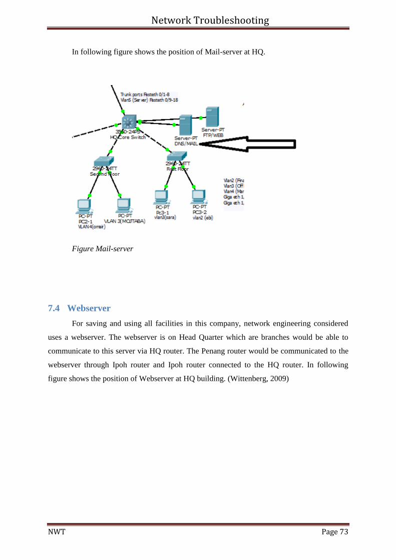
Network Troubleshooting
NWT Page 73
In following figure shows the position of Mail-server at HQ.
Figure Mail-server
7.4 Webserver
For saving and using all facilities in this company, network engineering considered
uses a webserver. The webserver is on Head Quarter which are branches would be able to
communicate to this server via HQ router. The Penang router would be communicated to the
webserver through Ipoh router and Ipoh router connected to the HQ router. In following
figure shows the position of Webserver at HQ building. (Wittenberg, 2009)
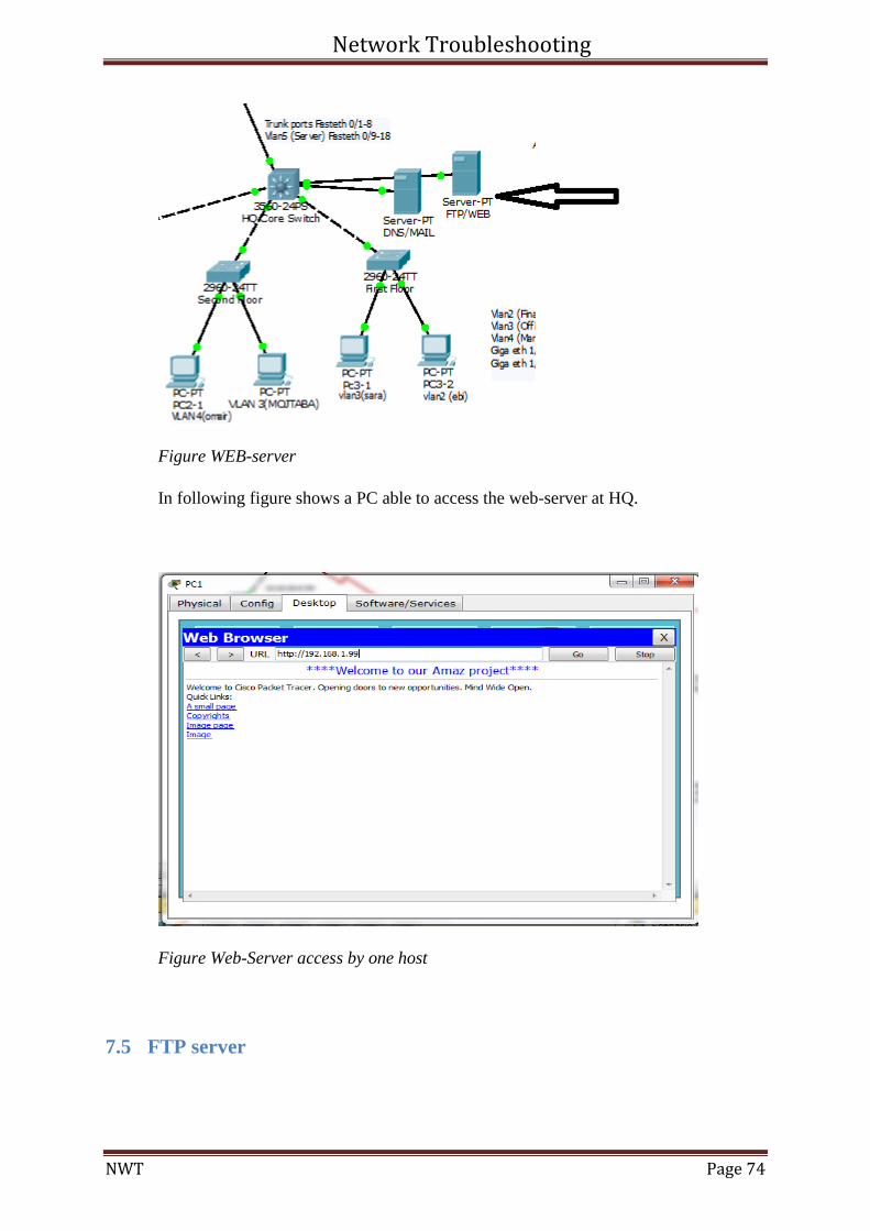
Network Troubleshooting
NWT Page 74
Figure WEB-server
In following figure shows a PC able to access the web-server at HQ.
Figure Web-Server access by one host
7.5 FTP server
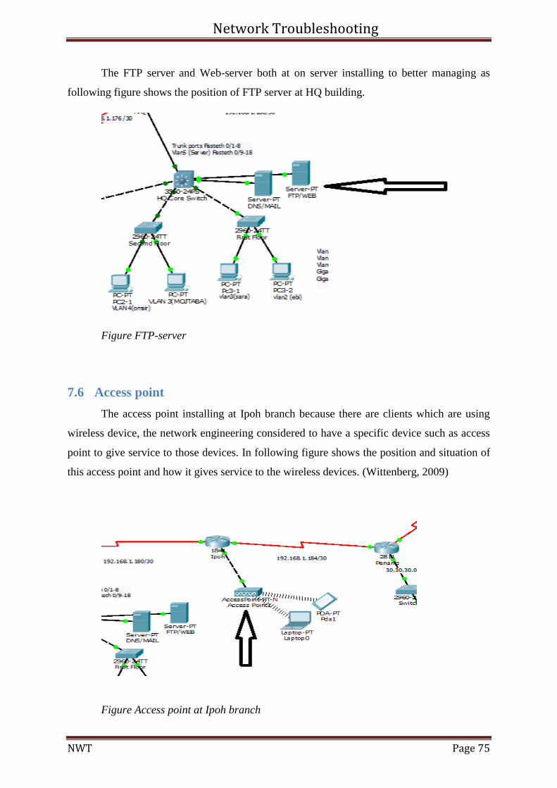
Network Troubleshooting
NWT Page 75
The FTP server and Web-server both at on server installing to better managing as
following figure shows the position of FTP server at HQ building.
Figure FTP-server
7.6 Access point
The access point installing at Ipoh branch because there are clients which are using
wireless device, the network engineering considered to have a specific device such as access
point to give service to those devices. In following figure shows the position and situation of
this access point and how it gives service to the wireless devices. (Wittenberg, 2009)
Figure Access point at Ipoh branch
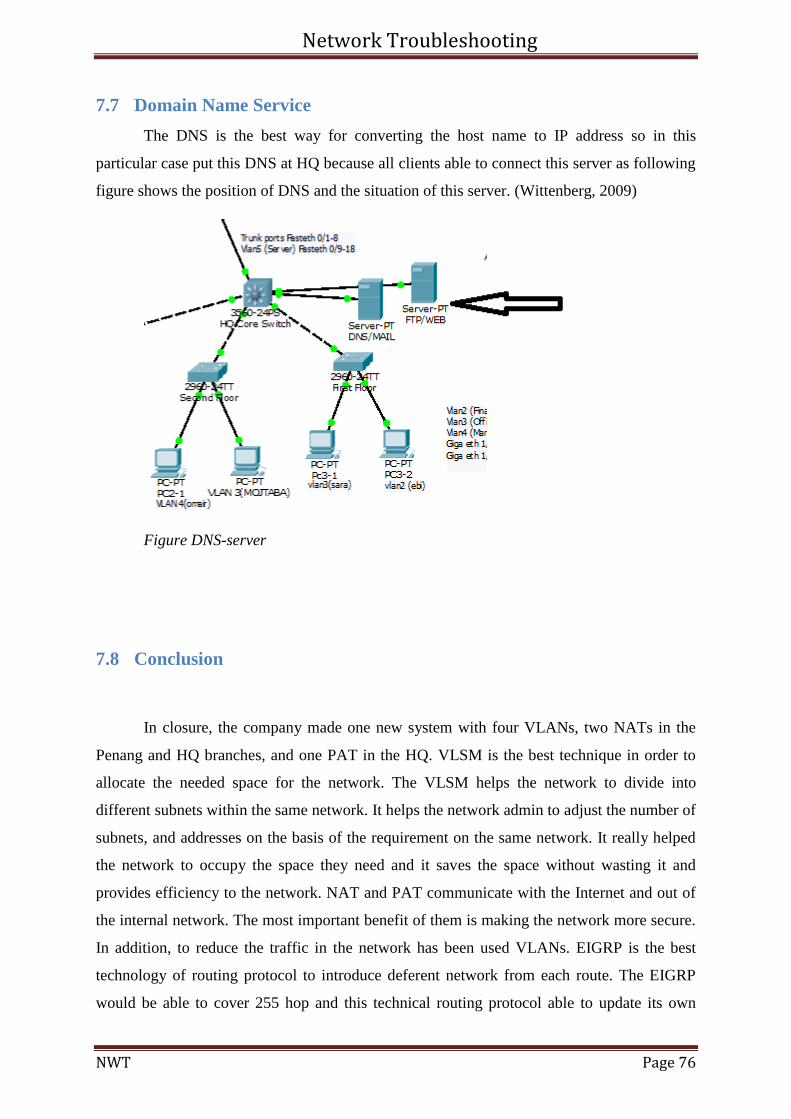
Network Troubleshooting
NWT Page 76
7.7 Domain Name Service
The DNS is the best way for converting the host name to IP address so in this
particular case put this DNS at HQ because all clients able to connect this server as following
figure shows the position of DNS and the situation of this server. (Wittenberg, 2009)
Figure DNS-server
7.8 Conclusion
In closure, the company made one new system with four VLANs, two NATs in the
Penang and HQ branches, and one PAT in the HQ. VLSM is the best technique in order to
allocate the needed space for the network. The VLSM helps the network to divide into
different subnets within the same network. It helps the network admin to adjust the number of
subnets, and addresses on the basis of the requirement on the same network. It really helped
the network to occupy the space they need and it saves the space without wasting it and
provides efficiency to the network. NAT and PAT communicate with the Internet and out of
the internal network. The most important benefit of them is making the network more secure.
In addition, to reduce the traffic in the network has been used VLANs. EIGRP is the best
technology of routing protocol to introduce deferent network from each route. The EIGRP
would be able to cover 255 hop and this technical routing protocol able to update its own
Network Troubleshooting
NWT Page 77
table of routing in 5 seconds because of each five seconds send hello packet to the next hop,
as well as EIGRP work on two speed slow and fast. This technical routing protocol able to
summarize automatic or manual. I hope you have enjoyed reading this documentation as
much as I have gathered information how to configure and the conceptual of routing protocol
and the benefit of using EIGRP technical routing protocol.
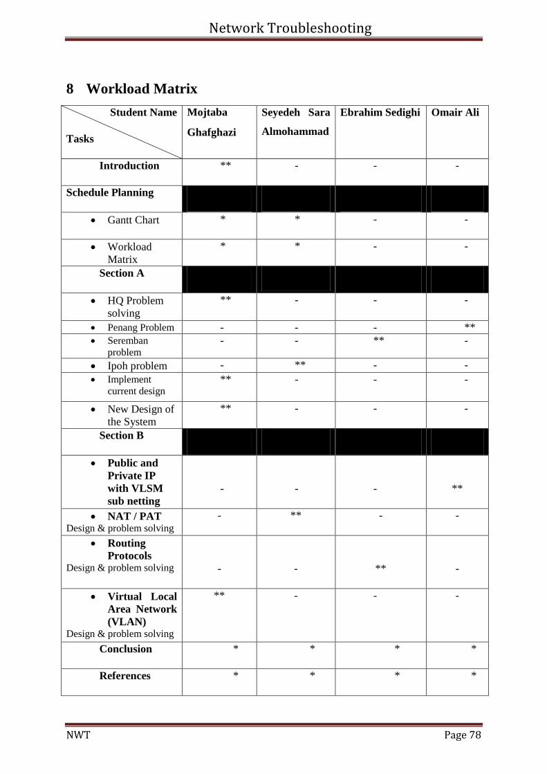
Network Troubleshooting
NWT Page 78
8 Workload Matrix
Student Name
Tasks
Mojtaba
Ghafghazi
Seyedeh Sara
Almohammad
Ebrahim Sedighi Omair Ali
Introduction ** - - -
Schedule Planning
Gantt Chart * * - -
Workload
Matrix
* * - -
Section A
HQ Problem
solving
** - - -
Penang Problem - - - **
Seremban
problem
- - ** -
Ipoh problem - ** - -
Implement
current design ** - - -
New Design of
the System
** - - -
Section B
Public and
Private IP
with VLSM
sub netting
-
-
-
**
NAT / PAT Design & problem solving
- ** - -
Routing
Protocols Design & problem solving
-
-
**
-
Virtual Local
Area Network
(VLAN) Design & problem solving
** -
- -
Conclusion * * * *
References * * * *
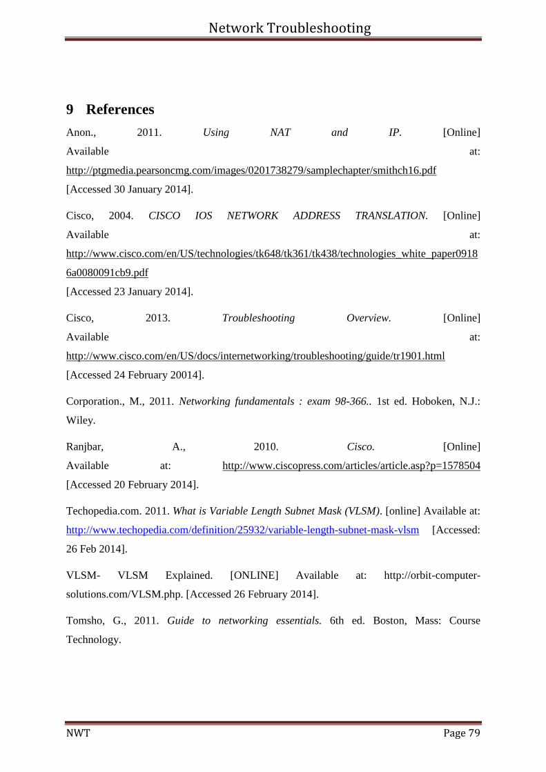
Network Troubleshooting
NWT Page 79
9 References
Anon., 2011. Using NAT and IP. [Online]
Available at:
http://ptgmedia.pearsoncmg.com/images/0201738279/samplechapter/smithch16.pdf
[Accessed 30 January 2014].
Cisco, 2004. CISCO IOS NETWORK ADDRESS TRANSLATION. [Online]
Available at:
http://www.cisco.com/en/US/technologies/tk648/tk361/tk438/technologies_white_paper0918
6a0080091cb9.pdf
[Accessed 23 January 2014].
Cisco, 2013. Troubleshooting Overview. [Online]
Available at:
http://www.cisco.com/en/US/docs/internetworking/troubleshooting/guide/tr1901.html
[Accessed 24 February 20014].
Corporation., M., 2011. Networking fundamentals : exam 98-366.. 1st ed. Hoboken, N.J.:
Wiley.
Ranjbar, A., 2010. Cisco. [Online]
Available at: http://www.ciscopress.com/articles/article.asp?p=1578504
[Accessed 20 February 2014].
Techopedia.com. 2011. What is Variable Length Subnet Mask (VLSM). [online] Available at:
http://www.techopedia.com/definition/25932/variable-length-subnet-mask-vlsm [Accessed:
26 Feb 2014].
VLSM- VLSM Explained. [ONLINE] Available at: http://orbit-computer-
solutions.com/VLSM.php. [Accessed 26 February 2014].
Tomsho, G., 2011. Guide to networking essentials. 6th ed. Boston, Mass: Course
Technology.
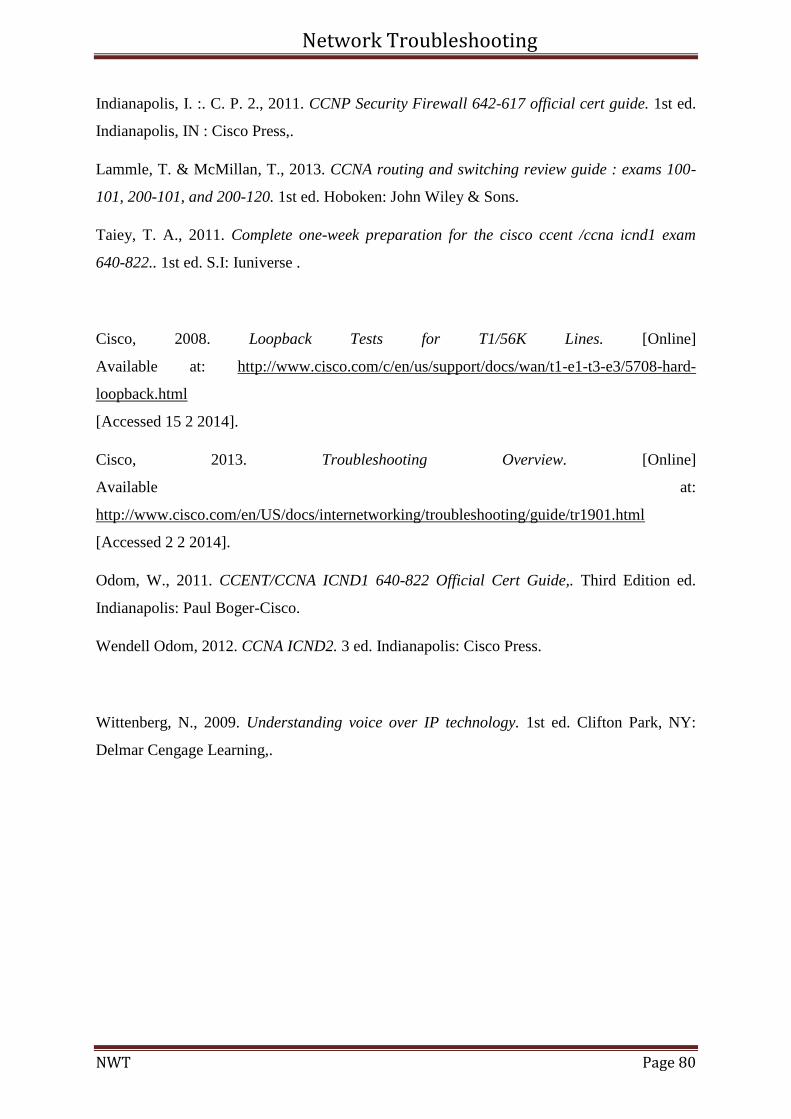
Network Troubleshooting
NWT Page 80
Indianapolis, I. :. C. P. 2., 2011. CCNP Security Firewall 642-617 official cert guide. 1st ed.
Indianapolis, IN : Cisco Press,.
Lammle, T. & McMillan, T., 2013. CCNA routing and switching review guide : exams 100-
101, 200-101, and 200-120. 1st ed. Hoboken: John Wiley & Sons.
Taiey, T. A., 2011. Complete one-week preparation for the cisco ccent /ccna icnd1 exam
640-822.. 1st ed. S.I: Iuniverse .
Cisco, 2008. Loopback Tests for T1/56K Lines. [Online]
Available at: http://www.cisco.com/c/en/us/support/docs/wan/t1-e1-t3-e3/5708-hard-
loopback.html
[Accessed 15 2 2014].
Cisco, 2013. Troubleshooting Overview. [Online]
Available at:
http://www.cisco.com/en/US/docs/internetworking/troubleshooting/guide/tr1901.html
[Accessed 2 2 2014].
Odom, W., 2011. CCENT/CCNA ICND1 640-822 Official Cert Guide,. Third Edition ed.
Indianapolis: Paul Boger-Cisco.
Wendell Odom, 2012. CCNA ICND2. 3 ed. Indianapolis: Cisco Press.
Wittenberg, N., 2009. Understanding voice over IP technology. 1st ed. Clifton Park, NY:
Delmar Cengage Learning,.
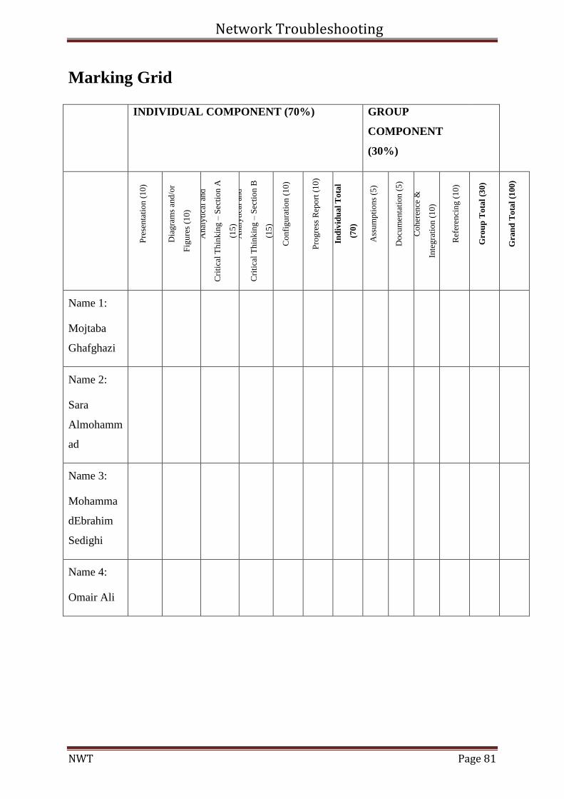
Network Troubleshooting
NWT Page 81
Marking Grid
INDIVIDUAL COMPONENT (70%) GROUP
COMPONENT
(30%)
Pre
sen
tati
on
(1
0)
Dia
gra
ms
and
/or
Fig
ure
s (1
0)
An
aly
tica
l an
d
Cri
tica
l T
hin
kin
g –
Sec
tio
n A
(15
) A
nal
yti
cal
and
Cri
tica
l T
hin
kin
g –
Sec
tio
n B
(15
)
Co
nfi
gu
rati
on
(1
0)
Pro
gre
ss R
epo
rt (
10
)
Ind
ivid
ua
l T
ota
l
(70
)
Ass
um
pti
on
s (5
)
Do
cum
enta
tion
(5
)
Co
her
ence
&
Inte
gra
tion
(1
0)
Ref
eren
cin
g (
10
)
Gro
up
To
tal
(30
)
Gra
nd
To
tal
(100
)
Name 1:
Mojtaba
Ghafghazi
Name 2:
Sara
Almohamm
ad
Name 3:
Mohamma
dEbrahim
Sedighi
Name 4:
Omair Ali