nx-591ne-gsm networx gsm 3g hspa+ module - interlogix
TRANSCRIPT
P/N 466-4433 • REV A • 25MAR13 1
NX-591NE-GSM NetworX GSM 3G HSPA+ Module Installation Sheet
Description
The NX-591NE-GSM is a microprocessor-controlled GSM
interface module used to connect the NetworX series of control
panels to GSM cellular networks for event reporting. The
module is compatible with the latest 3G and HSPA+ (4G)
networks, as well as backward compatible with 2G networks,
and can be used for primary or backup reporting. Flexible
event selection allows only specific messages to be reported,
keeping airtime to a minimum. The module interfaces with the
NetworX panel data bus and has 9 LEDs to provide extensive
diagnostic and setup information.
Activation
Before installing the module, it must be activated on an existing
dealer account. If you do not have a dealer account, please
contact Interlogix directly to initiate the account set-up
procedure. The activation process automatically activates the
module within a few hours. If you already have a dealer
account, you can activate and manage the module via our
website address: https://login.uplink.com/ge/login.aspx.
1. Enter your login name and password, then click
Login.
2. Click on Activate Unit on the left side of the page.
3. Enter the serial number of the module from label on
the front of the unit (10-digit number preceded by S/N)
and select Interlogix SMS Plan from the drop-down
menu, then click Activate.
4. Fill out the required information and select reporting
options, then click Update.
Installation
To install the module you will need to mount the unit in the
panel enclosure and wire the unit to the main security panel
within the enclosure.
Mounting
Inside the can, several two-holed insertion points have been
constructed. This allows for either vertical or horizontal
placement of the modules. The insertion points have two sizes
of holes, a larger hole and a smaller hole. The black plastic
PCB guides are grooved on one edge where the PC board will
be seated. The end with the half-moon protrusion fits into the
larger hole. The smaller hole is for the screw.
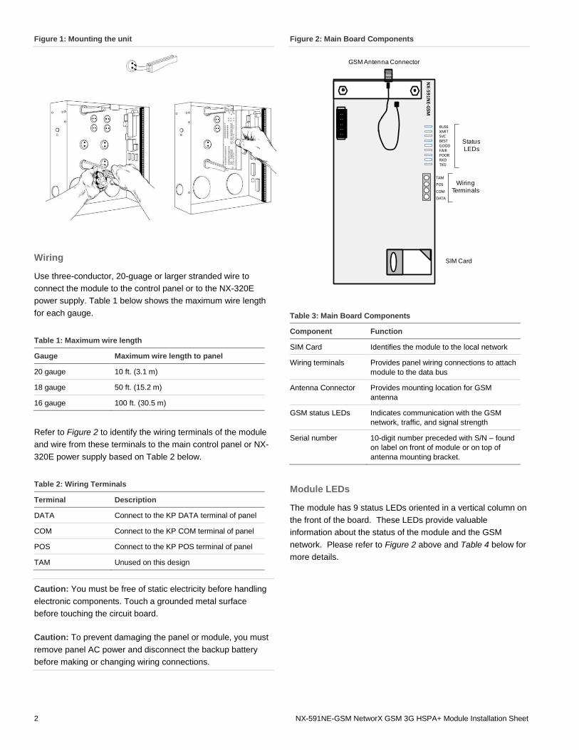
To mount the board, see Figure 1 and do the following:
1. Hold the board vertically, with antenna bracket facing to the
left, near the top of the inside of the panel enclosure to identify
the hole knockout that must be removed to allow for the
antenna to protrude through the top of the can. Note the two
insertion points that align with the board.
2. Remove the knockout from the hole with appropriate tools.
3. Place the first black plastic PCB guide in the top insertion
point, grooved edge downward. The half-moon protrusion will
be in the large hole. It does not require force.
4. Insert one of the provided screws into the smaller hole
(from the inside of the can) to secure it in place. A screwdriver
should reach through the notch that runs the length of the
guide to tighten the screw.
5. Position the second PCB guide opposite of the first
(grooved edge up) and placed in the lower insertion point,
using the same procedure.
6. Once mounted, screw it in securely.
7. Slide the board in the grooves of both guides with antenna
bracket facing left.
Note: Older style enclosures did not provide an exit hole for the
antenna included with the GSM module. In such cases, you must
either drill a new hole (5/8 in.) on top of the can or use an optional
external antenna (NX-501E-GSM).
2 NX-591NE-GSM NetworX GSM 3G HSPA+ Module Installation Sheet
Figure 1: Mounting the unit
Wiring
Use three-conductor, 20-guage or larger stranded wire to
connect the module to the control panel or to the NX-320E
power supply. Table 1 below shows the maximum wire length
for each gauge.
Table 1: Maximum wire length
Gauge Maximum wire length to panel
20 gauge 10 ft. (3.1 m)
18 gauge 50 ft. (15.2 m)
16 gauge 100 ft. (30.5 m)
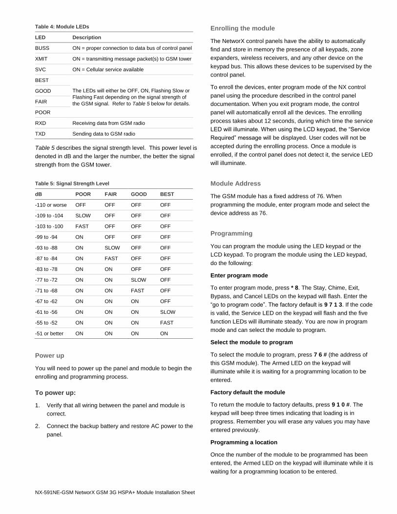
Refer to Figure 2 to identify the wiring terminals of the module
and wire from these terminals to the main control panel or NX-
320E power supply based on Table 2 below.
Table 2: Wiring Terminals
Terminal Description
DATA Connect to the KP DATA terminal of panel
COM Connect to the KP COM terminal of panel
POS Connect to the KP POS terminal of panel
TAM Unused on this design
Caution: You must be free of static electricity before handling
electronic components. Touch a grounded metal surface
before touching the circuit board.
Caution: To prevent damaging the panel or module, you must
remove panel AC power and disconnect the backup battery
before making or changing wiring connections.
Figure 2: Main Board Components
. .
. .
. .
. .
. .
NX
-59
1N
E-GSM
BUSSXMITSVCBESTGOODFAIRPOORRXDTXD
TAM
POS
COM
DATA
Wiring
Terminals
SIM Card
GSM Antenna Connector
Status
LEDs
Table 3: Main Board Components
Component Function
SIM Card Identifies the module to the local network
Wiring terminals Provides panel wiring connections to attach
module to the data bus
Antenna Connector Provides mounting location for GSM
antenna
GSM status LEDs Indicates communication with the GSM
network, traffic, and signal strength
Serial number 10-digit number preceded with S/N – found
on label on front of module or on top of
antenna mounting bracket.
Module LEDs
The module has 9 status LEDs oriented in a vertical column on
the front of the board. These LEDs provide valuable
information about the status of the module and the GSM
network. Please refer to Figure 2 above and Table 4 below for
more details.
NX-591NE-GSM NetworX GSM 3G HSPA+ Module Installation Sheet
Table 4: Module LEDs
LED Description
BUSS ON = proper connection to data bus of control panel
XMIT ON = transmitting message packet(s) to GSM tower
SVC ON = Cellular service available
BEST
The LEDs will either be OFF, ON, Flashing Slow or
Flashing Fast depending on the signal strength of
the GSM signal. Refer to Table 5 below for details.
GOOD
FAIR
POOR
RXD Receiving data from GSM radio
TXD Sending data to GSM radio
Table 5 describes the signal strength level. This power level is
denoted in dB and the larger the number, the better the signal
strength from the GSM tower.
Table 5: Signal Strength Level
dB POOR FAIR GOOD BEST
-110 or worse OFF OFF OFF OFF
-109 to -104 SLOW OFF OFF OFF
-103 to -100 FAST OFF OFF OFF
-99 to -94 ON OFF OFF OFF
-93 to -88 ON SLOW OFF OFF
-87 to -84 ON FAST OFF OFF
-83 to -78 ON ON OFF OFF
-77 to -72 ON ON SLOW OFF
-71 to -68 ON ON FAST OFF
-67 to -62 ON ON ON OFF
-61 to -56 ON ON ON SLOW
-55 to -52 ON ON ON FAST
-51 or better ON ON ON ON
Power up
You will need to power up the panel and module to begin the
enrolling and programming process.
To power up:
1. Verify that all wiring between the panel and module is
correct.
2. Connect the backup battery and restore AC power to the
panel.
Enrolling the module
The NetworX control panels have the ability to automatically
find and store in memory the presence of all keypads, zone
expanders, wireless receivers, and any other device on the
keypad bus. This allows these devices to be supervised by the
control panel.
To enroll the devices, enter program mode of the NX control
panel using the procedure described in the control panel
documentation. When you exit program mode, the control
panel will automatically enroll all the devices. The enrolling
process takes about 12 seconds, during which time the service
LED will illuminate. When using the LCD keypad, the “Service
Required” message will be displayed. User codes will not be
accepted during the enrolling process. Once a module is
enrolled, if the control panel does not detect it, the service LED
will illuminate.
Module Address
The GSM module has a fixed address of 76. When
programming the module, enter program mode and select the
device address as 76.
Programming
You can program the module using the LED keypad or the
LCD keypad. To program the module using the LED keypad,
do the following:
Enter program mode
To enter program mode, press * 8. The Stay, Chime, Exit,
Bypass, and Cancel LEDs on the keypad will flash. Enter the
“go to program code”. The factory default is 9 7 1 3. If the code
is valid, the Service LED on the keypad will flash and the five
function LEDs will illuminate steady. You are now in program
mode and can select the module to program.
Select the module to program
To select the module to program, press 7 6 # (the address of
this GSM module). The Armed LED on the keypad will
illuminate while it is waiting for a programming location to be
entered.
Factory default the module
To return the module to factory defaults, press 9 1 0 #. The
keypad will beep three times indicating that loading is in
progress. Remember you will erase any values you may have
entered previously.
Programming a location
Once the number of the module to be programmed has been
entered, the Armed LED on the keypad will illuminate while it is
waiting for a programming location to be entered.

4 NX-591NE-GSM NetworX GSM 3G HSPA+ Module Installation Sheet
Note: If an attempt is made to program an invalid entry for a
particular segment , the keypad sounder will emit a triple error beep,
and remain in that segment waiting for a valid entry.
To enter a location, enter the location number (1 to 13) and
press #. The Armed LED will flash. If the location is valid, the
Armed LED will extinguish, the Ready LED will illuminate, and
the zone LEDs will show the data for the first segment of this
location.
To change location data, enter the changed data. The Ready
LED will flash to indicate a data change in progress and will
continue until the data is saved. Press * to save the new data.
The keypad will advance to the next segment and display its
data. These steps are repeated until the last segment is
reached.
To exit a location, press #. The Ready LED will extinguish. The
Armed LED will illuminate waiting for a new programming
location to be entered.
To review the data, enter the location number and press #. The
Armed LED will flash. If the location number is valid, the Armed
LED will extinguish, the Ready LED will illuminate, and the
zone LEDs will show the binary data for the first segment of
this location. Press * to display the next segment data. Each
time you press *, the data of the next segment will be displayed
for review.
Exit program mode
Press Exit to exit this programming level. Press Exit a second
time to completely exit programming.
LCD keypad programming
All steps required for programming are the same as those
described for the LED keypad. The LCD keypad display will
prompt you for the data required. While in programming mode,
and not in a location, the number in parenthesis is the location
you were previously changing. For example, if the display
reads, “Enter location, then # (5)”, it is reminding you that
location 5 was the last location you programmed.
Programming data
Programming data is either numerical data, or feature selection
data.
Numerical data
To program numerical data, enter a number from 0 to 255 on
the numeric keys of the keypad. To view the data in a location,
a binary process is used. With this process, the LEDs for
zones 1 through 8 are used, and the numeric equivalents of
their illuminated LEDs are added together to determine the
data in a programming location. The numeric equivalents of
these LEDs are as follows:
Zone 1 LED = 1 Zone 2 LED = 2 Zone 3 LED = 4
Zone 4 LED = 8 Zone 5 LED = 16 Zone 6 LED = 32
Zone 7 LED = 64 Zone 8 LED = 128
For example, if the numerical data to be programmed in a
location is “66”, press 6 6 on the keypad. The LEDs for Zone 2
and Zone 7 will illuminate indicating 66 is in that location (2 +
64 = 66). Once the data is programmed, press * to enter the
data and advance to the next segment of that location.
After the last segment of a location is programmed, press * to
exit that location, turn the Ready LED off, and the Armed LED
on. You are now ready to enter another programming location.
If an attempt is made to program a number too large for a
particular segment, the keypad sounder will emit a triple beep,
indicating an error, and remain in that segment waiting for a
valid entry.
Feature selection data
Feature selection data will display the current condition (on or
off) of eight features associated with the programming location
and segment selected. Pressing a button on the touchpad (1
through 8) that corresponds to the feature number within a
segment will toggle (on/off) that feature. Pressing any numeric
key between 1 and 8 for selection of a feature will make the
corresponding LED illuminate (feature on). Press the number
again, and the LED will extinguish (feature off).
You will see that numerous features can be selected from
within one segment. For instance, if all eight features of a
segment are desired, pressing 1 2 3 4 5 6 7 8 will turn on LEDs
1 through 8 as you press the keys, indicating that those
features are enabled.
Note: On LCD keypads, the numbers of the enabled features will be
displayed. However, the features not enabled will display a hyphen (-).
After you select the desired setting for this segment, press * to
enter the data and automatically advance to the next segment
of the location. When you are in the last segment of a location
and press * to enter the data, you will exit that location. The
Ready LED will turn off and the Armed LED will turn on. You
are now ready to enter another programming location.
Location 0 – this location is not used.
Location 1, feature selection
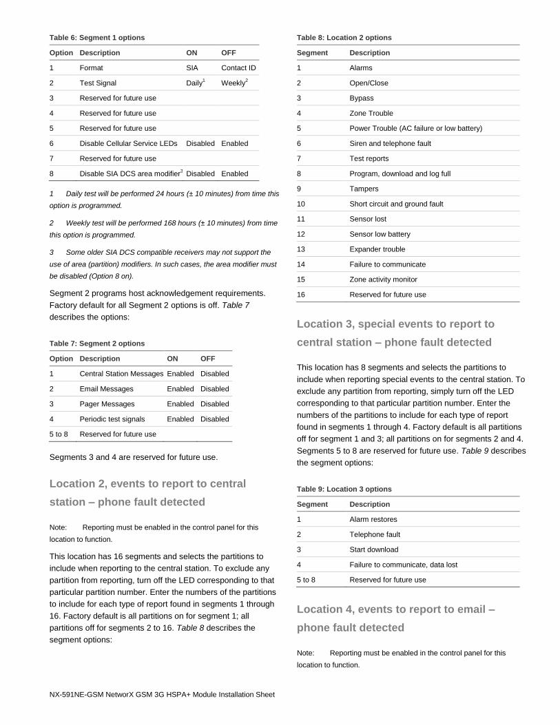
This location has four segments. Segment 1 contains the
options to be programmed for the functioning of this module.
Factory default for all Segment 1 options is off. Table 6
describes the options:
NX-591NE-GSM NetworX GSM 3G HSPA+ Module Installation Sheet
Table 6: Segment 1 options
Option Description ON OFF
1 Format SIA Contact ID
2 Test Signal Daily1 Weekly
2
3 Reserved for future use
4 Reserved for future use
5 Reserved for future use
6 Disable Cellular Service LEDs Disabled Enabled
7 Reserved for future use
8 Disable SIA DCS area modifier3 Disabled Enabled
1 Daily test will be performed 24 hours (± 10 minutes) from time this
option is programmed.
2 Weekly test will be performed 168 hours (± 10 minutes) from time
this option is programmed.
3 Some older SIA DCS compatible receivers may not support the
use of area (partition) modifiers. In such cases, the area modifier must
be disabled (Option 8 on).
Segment 2 programs host acknowledgement requirements.
Factory default for all Segment 2 options is off. Table 7
describes the options:
Table 7: Segment 2 options
Option Description ON OFF
1 Central Station Messages Enabled Disabled
2 Email Messages Enabled Disabled
3 Pager Messages Enabled Disabled
4 Periodic test signals Enabled Disabled
5 to 8 Reserved for future use
Segments 3 and 4 are reserved for future use.
Location 2, events to report to central
station – phone fault detected
Note: Reporting must be enabled in the control panel for this
location to function.
This location has 16 segments and selects the partitions to
include when reporting to the central station. To exclude any
partition from reporting, turn off the LED corresponding to that
particular partition number. Enter the numbers of the partitions
to include for each type of report found in segments 1 through
16. Factory default is all partitions on for segment 1; all
partitions off for segments 2 to 16. Table 8 describes the
segment options:
Table 8: Location 2 options
Segment Description
1 Alarms
2 Open/Close
3 Bypass
4 Zone Trouble
5 Power Trouble (AC failure or low battery)
6 Siren and telephone fault
7 Test reports
8 Program, download and log full
9 Tampers
10 Short circuit and ground fault
11 Sensor lost
12 Sensor low battery
13 Expander trouble
14 Failure to communicate
15 Zone activity monitor
16 Reserved for future use
Location 3, special events to report to
central station – phone fault detected
This location has 8 segments and selects the partitions to
include when reporting special events to the central station. To
exclude any partition from reporting, simply turn off the LED
corresponding to that particular partition number. Enter the
numbers of the partitions to include for each type of report
found in segments 1 through 4. Factory default is all partitions
off for segment 1 and 3; all partitions on for segments 2 and 4.
Segments 5 to 8 are reserved for future use. Table 9 describes
the segment options:
Table 9: Location 3 options
Segment Description
1 Alarm restores
2 Telephone fault
3 Start download
4 Failure to communicate, data lost
5 to 8 Reserved for future use
Location 4, events to report to email –
phone fault detected
Note: Reporting must be enabled in the control panel for this
location to function.
6 NX-591NE-GSM NetworX GSM 3G HSPA+ Module Installation Sheet
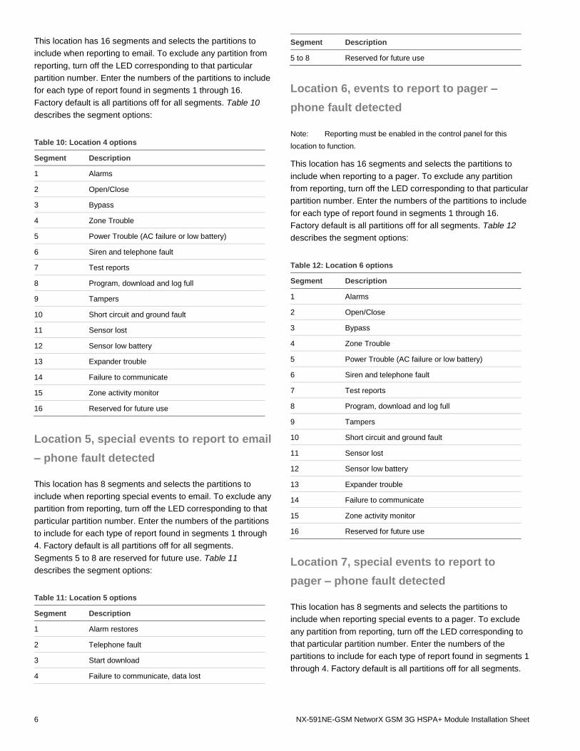
This location has 16 segments and selects the partitions to
include when reporting to email. To exclude any partition from
reporting, turn off the LED corresponding to that particular
partition number. Enter the numbers of the partitions to include
for each type of report found in segments 1 through 16.
Factory default is all partitions off for all segments. Table 10
describes the segment options:
Table 10: Location 4 options
Segment Description
1 Alarms
2 Open/Close
3 Bypass
4 Zone Trouble
5 Power Trouble (AC failure or low battery)
6 Siren and telephone fault
7 Test reports
8 Program, download and log full
9 Tampers
10 Short circuit and ground fault
11 Sensor lost
12 Sensor low battery
13 Expander trouble
14 Failure to communicate
15 Zone activity monitor
16 Reserved for future use
Location 5, special events to report to email
– phone fault detected
This location has 8 segments and selects the partitions to
include when reporting special events to email. To exclude any
partition from reporting, turn off the LED corresponding to that
particular partition number. Enter the numbers of the partitions
to include for each type of report found in segments 1 through
4. Factory default is all partitions off for all segments.
Segments 5 to 8 are reserved for future use. Table 11
describes the segment options:
Table 11: Location 5 options
Segment Description
1 Alarm restores
2 Telephone fault
3 Start download
4 Failure to communicate, data lost
Segment Description
5 to 8 Reserved for future use
Location 6, events to report to pager –
phone fault detected
Note: Reporting must be enabled in the control panel for this
location to function.
This location has 16 segments and selects the partitions to
include when reporting to a pager. To exclude any partition
from reporting, turn off the LED corresponding to that particular
partition number. Enter the numbers of the partitions to include
for each type of report found in segments 1 through 16.
Factory default is all partitions off for all segments. Table 12
describes the segment options:
Table 12: Location 6 options
Segment Description
1 Alarms
2 Open/Close
3 Bypass
4 Zone Trouble
5 Power Trouble (AC failure or low battery)
6 Siren and telephone fault
7 Test reports
8 Program, download and log full
9 Tampers
10 Short circuit and ground fault
11 Sensor lost
12 Sensor low battery
13 Expander trouble
14 Failure to communicate
15 Zone activity monitor
16 Reserved for future use
Location 7, special events to report to
pager – phone fault detected
This location has 8 segments and selects the partitions to
include when reporting special events to a pager. To exclude
any partition from reporting, turn off the LED corresponding to
that particular partition number. Enter the numbers of the
partitions to include for each type of report found in segments 1
through 4. Factory default is all partitions off for all segments.
NX-591NE-GSM NetworX GSM 3G HSPA+ Module Installation Sheet
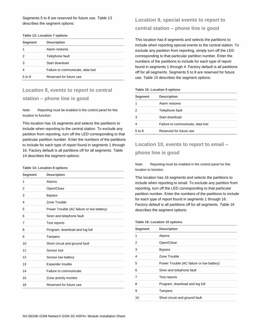
Segments 5 to 8 are reserved for future use. Table 13
describes the segment options:
Table 13: Location 7 options
Segment Description
1 Alarm restores
2 Telephone fault
3 Start download
4 Failure to communicate, data lost
5 to 8 Reserved for future use
Location 8, events to report to central
station – phone line is good
Note: Reporting must be enabled in the control panel for this
location to function.
This location has 16 segments and selects the partitions to
include when reporting to the central station. To exclude any
partition from reporting, turn off the LED corresponding to that
particular partition number. Enter the numbers of the partitions
to include for each type of report found in segments 1 through
16. Factory default is all partitions off for all segments. Table
14 describes the segment options:
Table 14: Location 8 options
Segment Description
1 Alarms
2 Open/Close
3 Bypass
4 Zone Trouble
5 Power Trouble (AC failure or low battery)
6 Siren and telephone fault
7 Test reports
8 Program, download and log full
9 Tampers
10 Short circuit and ground fault
11 Sensor lost
12 Sensor low battery
13 Expander trouble
14 Failure to communicate
15 Zone activity monitor
16 Reserved for future use
Location 9, special events to report to
central station – phone line is good
This location has 8 segments and selects the partitions to
include when reporting special events to the central station. To
exclude any partition from reporting, simply turn off the LED
corresponding to that particular partition number. Enter the
numbers of the partitions to include for each type of report
found in segments 1 through 4. Factory default is all partitions
off for all segments. Segments 5 to 8 are reserved for future
use. Table 15 describes the segment options:
Table 15: Location 9 options
Segment Description
1 Alarm restores
2 Telephone fault
3 Start download
4 Failure to communicate, data lost
5 to 8 Reserved for future use
Location 10, events to report to email –
phone line is good
Note: Reporting must be enabled in the control panel for this
location to function.
This location has 16 segments and selects the partitions to
include when reporting to email. To exclude any partition from
reporting, turn off the LED corresponding to that particular
partition number. Enter the numbers of the partitions to include
for each type of report found in segments 1 through 16.
Factory default is all partitions off for all segments. Table 16
describes the segment options:
Table 16: Location 10 options
Segment Description
1 Alarms
2 Open/Close
3 Bypass
4 Zone Trouble
5 Power Trouble (AC failure or low battery)
6 Siren and telephone fault
7 Test reports
8 Program, download and log full
9 Tampers
10 Short circuit and ground fault
8 NX-591NE-GSM NetworX GSM 3G HSPA+ Module Installation Sheet
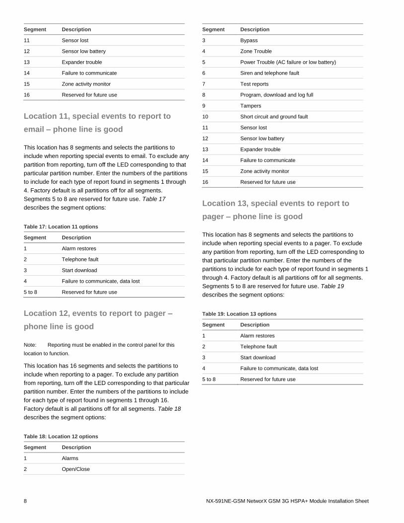
Segment Description
11 Sensor lost
12 Sensor low battery
13 Expander trouble
14 Failure to communicate
15 Zone activity monitor
16 Reserved for future use
Location 11, special events to report to
email – phone line is good
This location has 8 segments and selects the partitions to
include when reporting special events to email. To exclude any
partition from reporting, turn off the LED corresponding to that
particular partition number. Enter the numbers of the partitions
to include for each type of report found in segments 1 through
4. Factory default is all partitions off for all segments.
Segments 5 to 8 are reserved for future use. Table 17
describes the segment options:
Table 17: Location 11 options
Segment Description
1 Alarm restores
2 Telephone fault
3 Start download
4 Failure to communicate, data lost
5 to 8 Reserved for future use
Location 12, events to report to pager –
phone line is good
Note: Reporting must be enabled in the control panel for this
location to function.
This location has 16 segments and selects the partitions to
include when reporting to a pager. To exclude any partition
from reporting, turn off the LED corresponding to that particular
partition number. Enter the numbers of the partitions to include
for each type of report found in segments 1 through 16.
Factory default is all partitions off for all segments. Table 18
describes the segment options:
Table 18: Location 12 options
Segment Description
1 Alarms
2 Open/Close
Segment Description
3 Bypass
4 Zone Trouble
5 Power Trouble (AC failure or low battery)
6 Siren and telephone fault
7 Test reports
8 Program, download and log full
9 Tampers
10 Short circuit and ground fault
11 Sensor lost
12 Sensor low battery
13 Expander trouble
14 Failure to communicate
15 Zone activity monitor
16 Reserved for future use
Location 13, special events to report to
pager – phone line is good
This location has 8 segments and selects the partitions to
include when reporting special events to a pager. To exclude
any partition from reporting, turn off the LED corresponding to
that particular partition number. Enter the numbers of the
partitions to include for each type of report found in segments 1
through 4. Factory default is all partitions off for all segments.
Segments 5 to 8 are reserved for future use. Table 19
describes the segment options:
Table 19: Location 13 options
Segment Description
1 Alarm restores
2 Telephone fault
3 Start download
4 Failure to communicate, data lost
5 to 8 Reserved for future use
NX-591NE-GSM NetworX GSM 3G HSPA+ Module Installation Sheet
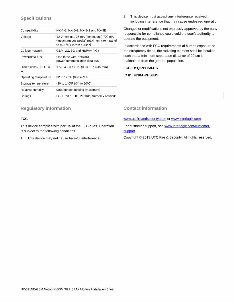
Specifications
Compatibility NX-4v2, NX-6v2, NX-8v2 and NX-8E
Voltage 12 V nominal, 25 mA (continuous) 700 mA
(instantaneous peaks) maximum (from panel
or auxiliary power supply)
Cellular network GSM, 2G, 3G and HSPA+ (4G)
Power/data bus One three-wire NetworX
power/communication data bus
Dimensions (D × H ×
W)
1.5 × 4.2 × 1.8 in. (38 × 107 × 45 mm)
Operating temperature 32 to 120ºF (0 to 49ºC)
Storage temperature -30 to 140ºF (-34 to 60ºC)
Relative humidity 90% noncondensing (maximum)
Listings FCC Part 15, IC, PTCRB, Numerex network
Regulatory information
FCC
This device complies with part 15 of the FCC rules. Operation
is subject to the following conditions.
1. This device may not cause harmful interference.
2. This device must accept any interference received,
including interference that may cause undesired operation.
Changes or modifications not expressly approved by the party
responsible for compliance could void the user’s authority to
operate the equipment.
In accordance with FCC requirements of human exposure to
radiofrequency fields, the radiating element shall be installed
such that a minimum separation distance of 20 cm is
maintained from the general population.
FCC ID: QIPPHS8-US
IC ID: 7830A-PHS8US
Contact information
www.utcfireandsecurity.com or www.interlogix.com
For customer support, see www.interlogix.com/customer-
support
Copyright © 2013 UTC Fire & Security. All rights reserved.
10 NX-591NE-GSM NetworX GSM 3G HSPA+ Module Installation Sheet
Programming Worksheets
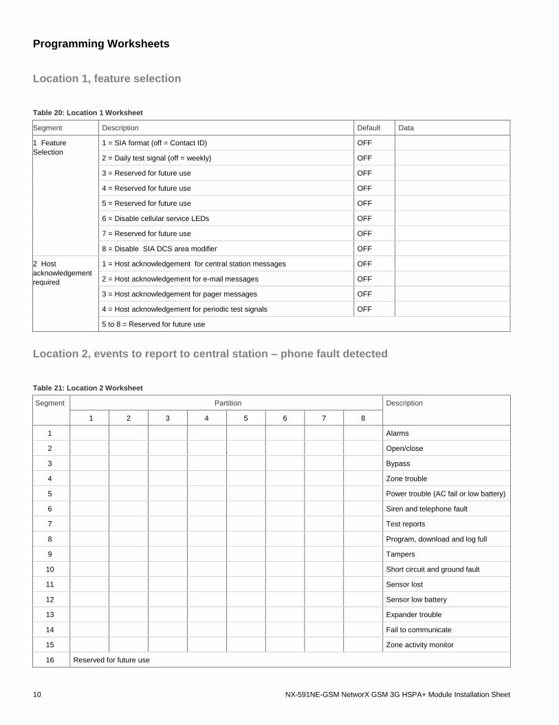
Location 1, feature selection
Table 20: Location 1 Worksheet
Segment Description Default Data
1 Feature
Selection
1 = SIA format (off = Contact ID) OFF
2 = Daily test signal (off = weekly) OFF
3 = Reserved for future use OFF
4 = Reserved for future use OFF
5 = Reserved for future use OFF
6 = Disable cellular service LEDs OFF
7 = Reserved for future use OFF
8 = Disable SIA DCS area modifier OFF
2 Host
acknowledgement
required
1 = Host acknowledgement for central station messages OFF
2 = Host acknowledgement for e-mail messages OFF
3 = Host acknowledgement for pager messages OFF
4 = Host acknowledgement for periodic test signals OFF
5 to 8 = Reserved for future use
Location 2, events to report to central station – phone fault detected
Table 21: Location 2 Worksheet
Segment Partition Description
1 2 3 4 5 6 7 8
1 Alarms
2 Open/close
3 Bypass
4 Zone trouble
5 Power trouble (AC fail or low battery)
6 Siren and telephone fault
7 Test reports
8 Program, download and log full
9 Tampers
10 Short circuit and ground fault
11 Sensor lost
12 Sensor low battery
13 Expander trouble
14 Fail to communicate
15 Zone activity monitor
16 Reserved for future use
NX-591NE-GSM NetworX GSM 3G HSPA+ Module Installation Sheet
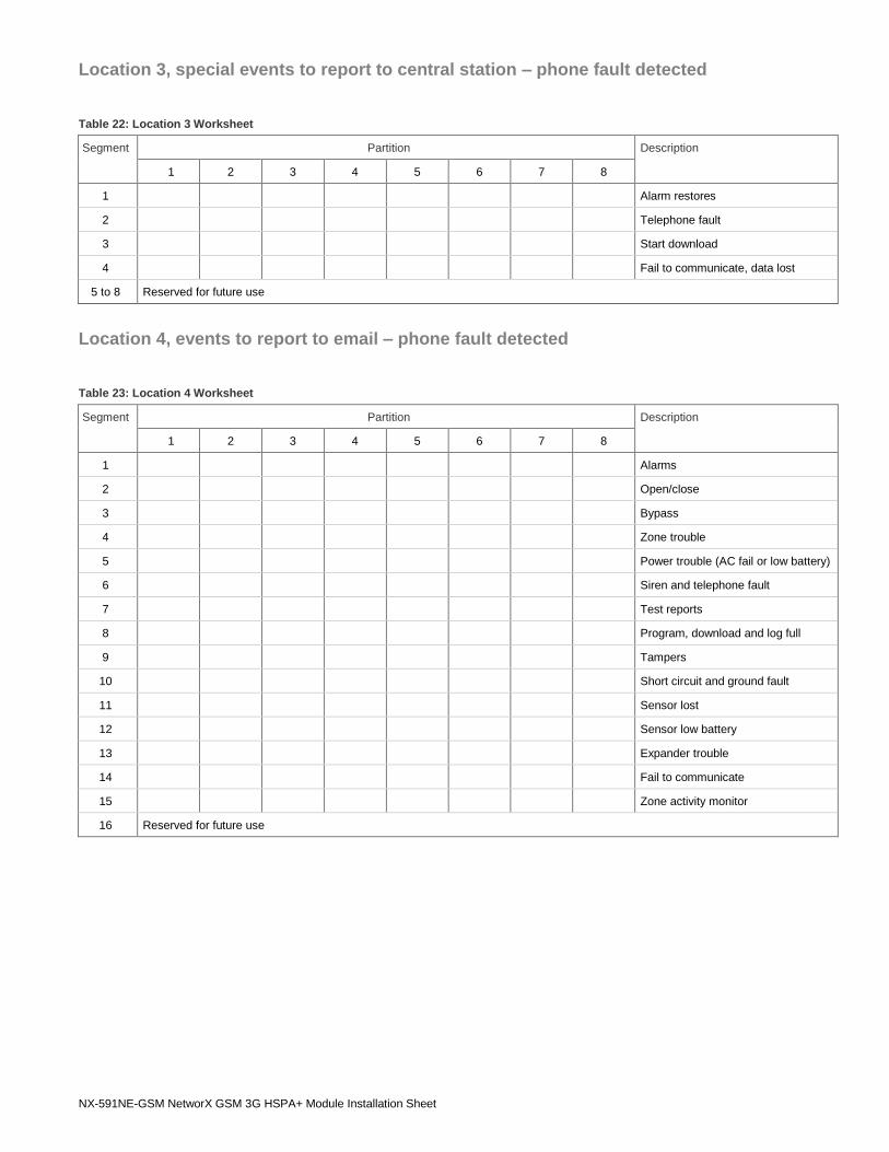
Location 3, special events to report to central station – phone fault detected
Table 22: Location 3 Worksheet
Segment Partition Description
1 2 3 4 5 6 7 8
1 Alarm restores
2 Telephone fault
3 Start download
4 Fail to communicate, data lost
5 to 8 Reserved for future use
Location 4, events to report to email – phone fault detected
Table 23: Location 4 Worksheet
Segment Partition Description
1 2 3 4 5 6 7 8
1 Alarms
2 Open/close
3 Bypass
4 Zone trouble
5 Power trouble (AC fail or low battery)
6 Siren and telephone fault
7 Test reports
8 Program, download and log full
9 Tampers
10 Short circuit and ground fault
11 Sensor lost
12 Sensor low battery
13 Expander trouble
14 Fail to communicate
15 Zone activity monitor
16 Reserved for future use
12 NX-591NE-GSM NetworX GSM 3G HSPA+ Module Installation Sheet
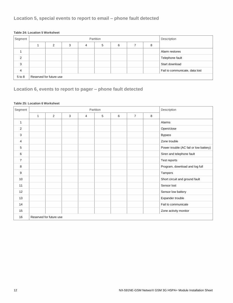
Location 5, special events to report to email – phone fault detected
Table 24: Location 5 Worksheet
Segment Partition Description
1 2 3 4 5 6 7 8
1 Alarm restores
2 Telephone fault
3 Start download
4 Fail to communicate, data lost
5 to 8 Reserved for future use
Location 6, events to report to pager – phone fault detected
Table 25: Location 6 Worksheet
Segment Partition Description
1 2 3 4 5 6 7 8
1 Alarms
2 Open/close
3 Bypass
4 Zone trouble
5 Power trouble (AC fail or low battery)
6 Siren and telephone fault
7 Test reports
8 Program, download and log full
9 Tampers
10 Short circuit and ground fault
11 Sensor lost
12 Sensor low battery
13 Expander trouble
14 Fail to communicate
15 Zone activity monitor
16 Reserved for future use
NX-591NE-GSM NetworX GSM 3G HSPA+ Module Installation Sheet
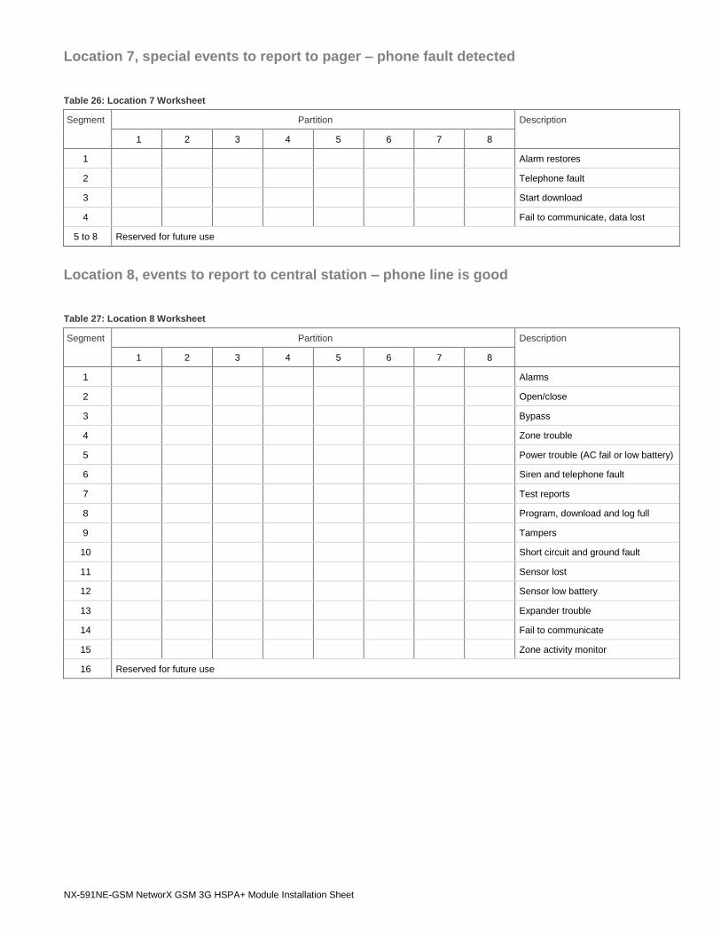
Location 7, special events to report to pager – phone fault detected
Table 26: Location 7 Worksheet
Segment Partition Description
1 2 3 4 5 6 7 8
1 Alarm restores
2 Telephone fault
3 Start download
4 Fail to communicate, data lost
5 to 8 Reserved for future use
Location 8, events to report to central station – phone line is good
Table 27: Location 8 Worksheet
Segment Partition Description
1 2 3 4 5 6 7 8
1 Alarms
2 Open/close
3 Bypass
4 Zone trouble
5 Power trouble (AC fail or low battery)
6 Siren and telephone fault
7 Test reports
8 Program, download and log full
9 Tampers
10 Short circuit and ground fault
11 Sensor lost
12 Sensor low battery
13 Expander trouble
14 Fail to communicate
15 Zone activity monitor
16 Reserved for future use
14 NX-591NE-GSM NetworX GSM 3G HSPA+ Module Installation Sheet
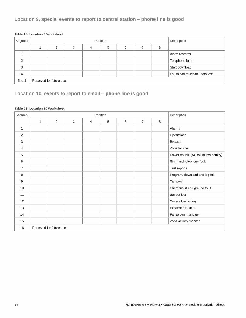
Location 9, special events to report to central station – phone line is good
Table 28: Location 9 Worksheet
Segment Partition Description
1 2 3 4 5 6 7 8
1 Alarm restores
2 Telephone fault
3 Start download
4 Fail to communicate, data lost
5 to 8 Reserved for future use
Location 10, events to report to email – phone line is good
Table 29: Location 10 Worksheet
Segment Partition Description
1 2 3 4 5 6 7 8
1 Alarms
2 Open/close
3 Bypass
4 Zone trouble
5 Power trouble (AC fail or low battery)
6 Siren and telephone fault
7 Test reports
8 Program, download and log full
9 Tampers
10 Short circuit and ground fault
11 Sensor lost
12 Sensor low battery
13 Expander trouble
14 Fail to communicate
15 Zone activity monitor
16 Reserved for future use
NX-591NE-GSM NetworX GSM 3G HSPA+ Module Installation Sheet
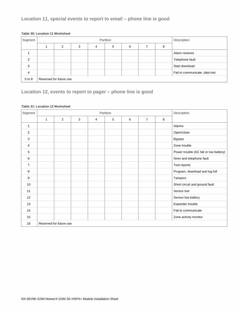
Location 11, special events to report to email – phone line is good
Table 30: Location 11 Worksheet
Segment Partition Description
1 2 3 4 5 6 7 8
1 Alarm restores
2 Telephone fault
3 Start download
4 Fail to communicate, data lost
5 to 8 Reserved for future use
Location 12, events to report to pager – phone line is good
Table 31: Location 12 Worksheet
Segment Partition Description
1 2 3 4 5 6 7 8
1 Alarms
2 Open/close
3 Bypass
4 Zone trouble
5 Power trouble (AC fail or low battery)
6 Siren and telephone fault
7 Test reports
8 Program, download and log full
9 Tampers
10 Short circuit and ground fault
11 Sensor lost
12 Sensor low battery
13 Expander trouble
14 Fail to communicate
15 Zone activity monitor
16 Reserved for future use
16 NX-591NE-GSM NetworX GSM 3G HSPA+ Module Installation Sheet
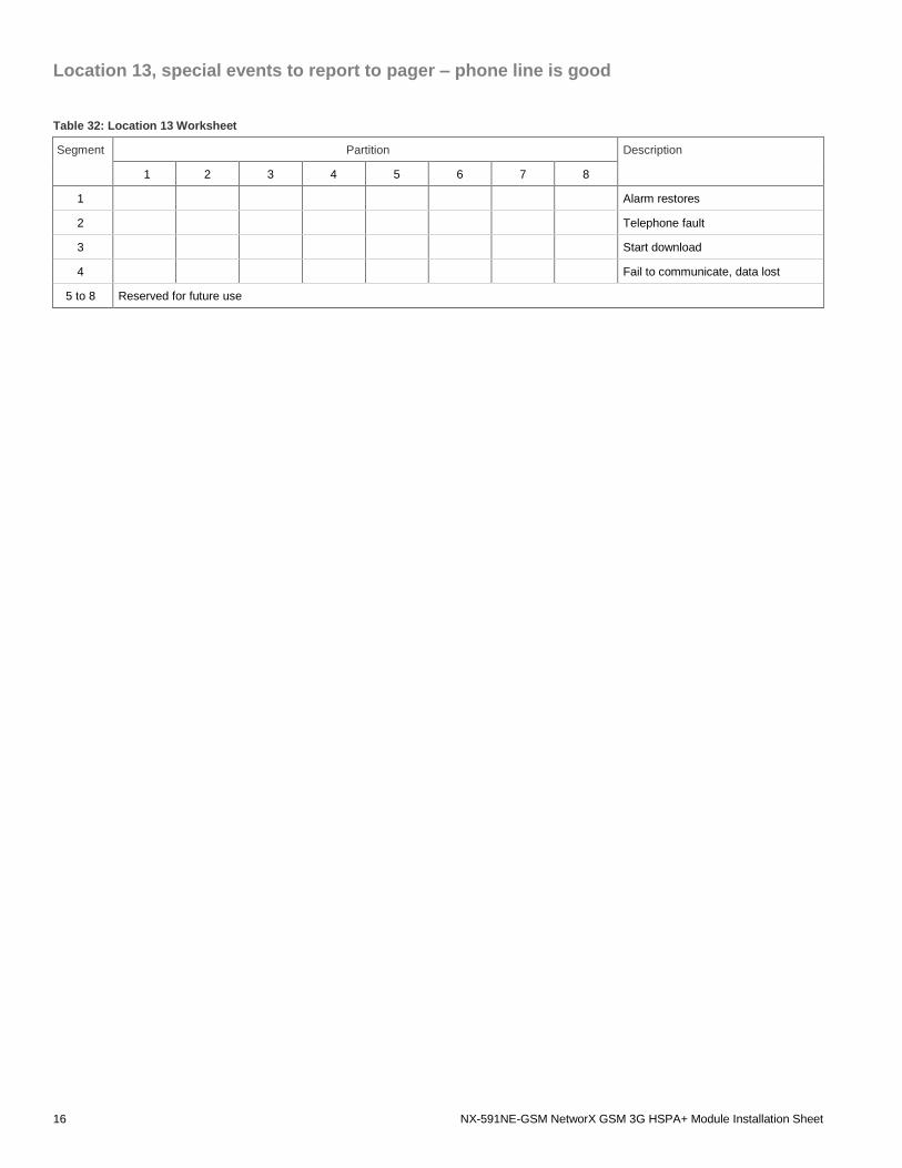
Location 13, special events to report to pager – phone line is good
Table 32: Location 13 Worksheet
Segment Partition Description
1 2 3 4 5 6 7 8
1 Alarm restores
2 Telephone fault
3 Start download
4 Fail to communicate, data lost
5 to 8 Reserved for future use