nx for mechanical design fact sheet
TRANSCRIPT
NX for Mechanical Design
www.siemens.com/nx
NX
Benefits Facilitates design control, speeds the design process, increases designer and design team productivity and improves design throughput
Improves design team performance, especially for handling large, complex models
Raises product quality by minimizing design errors
Produces faster, more accurate and complete product documentation
Produces significant time, effort and cost savings by facilitating design re-use
Facilitates better integration and coordination between multiple design disciplines, design teams and their related CAD systems
Features Comprehensive 3D design capabilities, including wireframe, surface, solid and direct modeling
Synchronous technology for uniting parametric and history-free modeling in the same design environment
Assembly modeling with full-context, multi-CAD digital mockup and validation tools
SummaryThe NX™ software for mechanical design provides a comprehensive set of leading-edge CAD modeling tools that enable companies to design higher quality products faster and less expensively. The NX comprehensive mechanical design solution lets you choose the tools and methodologies that best suit your design challenge. Innovative technologies deliver breakthrough mechanical design capabilities that set new standards for speed, performance and ease-of-use.
Transforming product development by delivering greater power, speed, quality, productivity and efficiency for mechanical designNX mechanical design capabilities are unmatched in terms of the power, versatility, flexibility and productivity they deliver to your digital product development environment. NX enables you to establish a complete design solution for your environment, including leading-edge tools and methodologies for:
Comprehensive high-performance modeling, which enables you to seamlessly use the most productive modeling approaches – from explicit solid and surface modeling to parametric, process-specific and history-free direct modeling that works with models from any CAD system.
Active mockup and assembly design, which enables you to work interactively with massive multi-CAD assemblies while leveraging leading assembly management and engineering tools.
Standards-compliant drafting and 3D annotation, which streamlines the creation of product documentation by directly leveraging your 3D master model.
Today’s mechanical design challengesManufacturing companies are driven by an increased pressure to develop more innovative products in a shorter time frame while continuing to deliver high levels of quality. Even with mature 3D CAD technology, many companies fail to significantly reduce process waste, improve product quality or deliver breakthrough product innovations that stir the imagination of the marketplace.
These challenges require a radical rethinking of the business model that pertains to product development. This rethinking should begin with transforming the design process. Product design fuels the entire development
Process innovation NX enables you to establish an interactive environment where everyday design work can be streamlined through the implementation of task-oriented workflows that improve designer productivity. NX design environments facilitate high-performance modeling techniques that provide design teams with the flexibility and power to handle design of virtually any size or complexity. NX allows you to dynamically integrate your CAD processes with planning, simulation, tooling, manufac-turing and other lifecycle processes and make informed design decisions by recognizing the requirements of all design stakeholders and coordinating their activity.
More specifically, NX addresses the mechanical design process directly through its capabilities for:
Comprehensive high-performance modeling
Active mockup and assembly design Standards-compliant drafting and 3D annotation
Comprehensive high-performance modelingNX delivers the most powerful and flexible modeling solutions available – solutions that enable you to freely use any modeling technique that fits your design challenge. All NX modeling tools are built on Siemens’ Parasolid® geometry modeling kernel, the world’s most powerful, robust and widely used modeling foundation.
Design Freedom NX supports Design Freedom powered by Siemens’ groundbreaking synchronous technology. This unique approach enables you to unite feature-based parametric and history-free modeling in the same design environment.
Design Freedom means that your designers can use NX synchronous modeling tools to modify design geometry initially created on other CAD systems or by other modeling techniques. It does not matter whether the data in question was imported from another CAD system or whether is native parametric or nonparametric. NX
effort. Today’s design processes involve increasingly complex products comprised of design elements created by multiple teams, disciplines and suppliers using independent CAD systems. These complex processes require product makers to coordinate the activities of team members dispersed across different geographies while retaining design intent from the start of the design project to its completion.
Companies need design processes that compress the design cycle by eliminating value-added tasks, maximizing knowledge re-use and proactively addressing manufacturability issues before they reach the factory floor. Product developers need to “design-in” rather than “inspect-in” product quality.
NX next-generation design solutionsNX delivers next-generation design solutions that transform the entire product development cycle. NX represents a radical departure from conventional CAD systems. NX improves speed and efficiency while eliminating wasted work by providing unique technologies and methodologies, including:
Knowledge-enabled design NX automates and simplifies design by enabling you to leverage the product and process knowledge that your company has gained from its experiences as well as from industry best practices. NX tools enable designers to capture knowledge in the form of high-level product structure, templates, frequently used design features, engineering rules, formulae and validation checks. Knowledge-enabled design helps your company reduce design costs, compress the design cycle and improve design quality.
You can manage your entire design process with Siemens’ Teamcenter® software, which lets you establish and seamlessly integrate a single source of product and process knowledge into your design environment. This enables you to coordinate your design chain, standardize your design processes and accelerate decision making throughout the design cycle.
NX for Mechanical Design
Features continued Interactive design of massive assemblies that improves the performance and capacity of your design environment
Process-specific, streamlined modeling tools for sheet metal routed systems and other applications
Configurable, intuitive interface that facilitates ease-of-use, user learning and accessibility to powerful modeling capabilities
Associative integration with all NX product development solutions, including NX industrial design, electromechanical, simulation, tooling and machining solutions
Automated, real-time design validation checking to monitor functional requirements
Knowledge capture and automation tools
Seamlessly integrated, transparent engineering data and process management
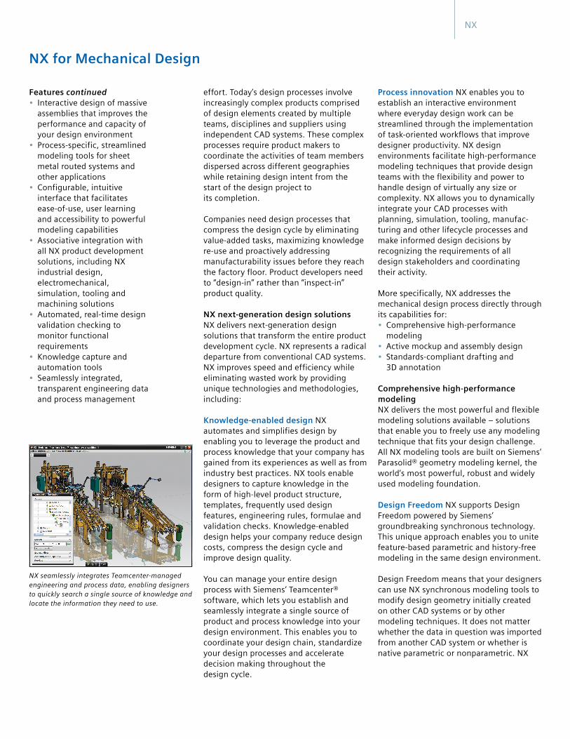
NX seamlessly integrates Teamcenter-managed engineering and process data, enabling designers to quickly search a single source of knowledge and locate the information they need to use.
NX

subassemblies and components. Active Mockup utilizes industry-standard JT™ technology to enable designers to load thousands of components from multiple CAD systems in just seconds. JT is a highly flexible CAD neutral format that allows designers to fully represent all relevant model information. The JT format can be created from most major CAD applications. Depending on your type of business process, JT data can be very lightweight or very rich. JT models are able to hold precise model geometry, product structures, attributes and PMI, including geometric data, translations and annotations. JT enables you to load assemblies with up to a million parts with exceptional interactive performance.
As a result, Active Mockup provides designers with a true interactive design capability that lets them rapidly display, section and rotate very large assemblies. Active Mockup enables design teams to collaborate by viewing, modifying and evaluating complete digital mockups. Teams can view as much of the product design as required to evaluate its parts in the context of a particular task. These design-in-context capabilities facilitate rapid problem resolution during the physical assembly process.
Assembly design validation NX provides validation tools that enable your designers to identify and resolve assembly design and process problems in the early stages of development – without resorting to physical prototyping. NX enables designers to perform interactive clearance checking and interference checking to detect and
Design re-use Design re-use becomes increasingly more important as today’s manufacturers try to expand their market share by establishing product platforms. NX lets you use any part or assembly as a template for new designs, building product knowledge and best practices into your development processes. This capability supports your commonization, modularization and re-use initiatives by enabling you to reduce design time by up to 80 percent.
Active mockup and assembly designNX powerful mockup and assembly capabilities provide your design environment with a variety of interactive capabilities that expedite your assembly design and engineering processes.
Active Mockup NX Active Mockup enables your designers to easily navigate large assemblies and establish an appro-priate environment for detailed work on
synchronous tools enable designers to work directly with any geometry without the need to rebuild data. These synchronous tools let designers use parametric features without the limitations of a feature history.
Process-specific modeling Conventional CAD systems leave it up to the designer to figure out how to apply a system’s various tools. In contrast, NX logically structures commands in workflows oriented to accomplishing specific design tasks. NX is prepackaged with industry roles that tailor the user interface and incorporate best practice guidelines. NX also delivers process-based tools that build in domain expertise for meeting specific challenges (such as dealing with sheet metal components) or for performing industry-specific processes (such as handling automotive body structures and general packaging). Process-specific design aids enable designers to work faster than general purpose CAD tools.
NX
NX synchronous technology enables designers to perform history-free editing on imported CAD models.
Sheet metal design is one of several streamlined process-specific modeling tools provided by NX.
NX knowledge-enabled design tools let companies re-use existing designs as customized templates for new designs.
NX Active Mockup and assembly management enables collaborative design to be performed in the full context of complex assemblies.
NX assembly validation tools include extraction path planning capabilities that optimize designs so that a product can be easily assembled, disassembled and maintained.
NX drafting capabilities enable designers to rapidly lay out their drawings, as well as to create drawing views, detailing and dimensioning and geometric dimensioning and tolerancing (GD&T). Since NX adheres to the industry standards for PMI 3D model annotation, the dimensions, symbols and tolerances can be automatically inherited on drawing views and directly used by downstream analysis and manufacturing applications. This improves productivity by eliminating the need to re-enter this information.
Standards-compliant drafting and 3D annotationNX delivers production-driven tools for documenting your designs either as standards-compliant 2D drawings or 3D product and manufacturing information (PMI) annotations. You can use these capabilities to ensure that design intent is properly communicated throughout your development organization. They improve product quality by removing potential sources of interpretation error from your design environment and by speeding the process you use to take your designs to manufacturing.
© 2011 Siemens Product Lifecycle Management Software Inc. All rights reserved. Siemens and the Siemens logo are registered trademarks of Siemens AG. D-Cubed, Femap, Geolus, GO PLM, I-deas, Insight, JT, NX, Parasolid, Solid Edge, Teamcenter, Tecnomatix and Velocity Series are trademarks or registered trademarks of Siemens Product Lifecycle Management Software Inc. or its subsidiaries in the United States and in other countries. All other logos, trademarks, registered trademarks or service marks used herein are the property of their respective holders. X8 14543 11/11 B
www.siemens.com/plm
ContactSiemens Industry SoftwareAmericas +1 800 498 5351Europe +44 (0) 1276 702000Asia-Pacific +852 2230 3333
eliminate fit problems. Designers can interactively simulate assembly motion to check and optimize moving components.
With automated assembly path planning and motion envelopes, designers can optimize products for assembly, disassembly, maintenance and service. Designers can record and play back assembly and motion sequences as movies that can be shared as assembly instructions with the factory floor. These simple to use tools can be leveraged to quickly validate design changes as the product evolves.
Routed systems design NX provides tools that enable designers to create and validate routed subsystems for both mechanical and electrical designs. Mechanical routing tools and libraries are available for tubing, piping and steelwork. Electrical routing tools enable designers to place wiring, conduit and raceways while standard component libraries are available for electrical systems. NX electrical routing includes wire harness design and manufacturing support, eliminating the need for physical prototype and reducing product development time by allowing designers to perform interface checks, validate design rules, visualize the routing pattern in 3D and trace the location of specific wires and connections.
NX maintains associative links between the P&ID layout and the 3D systems to ensure that system logic is maintained. Designers can quickly apply logical design changes to the routed system. Routed systems are fully associative to NX assemblies to facilitate design changes. Automated bill of material and other reporting provide information for subsystem manufacturing.
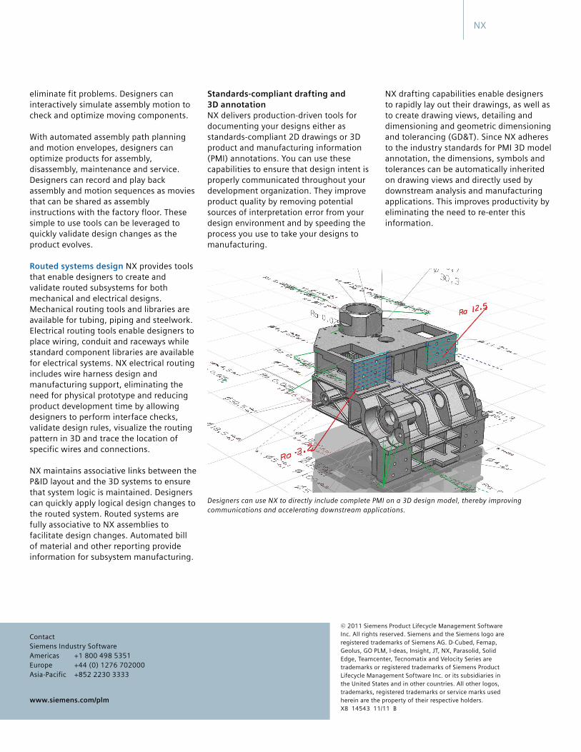
Designers can use NX to directly include complete PMI on a 3D design model, thereby improving communications and accelerating downstream applications.
NX
NX Mach Series Industrial Design
www.siemens.com/nx
NX
Features Summary
Free form modeling
Basic free form modeling
Dynamic and photorealistic rendering
Solid and feature-based modeling
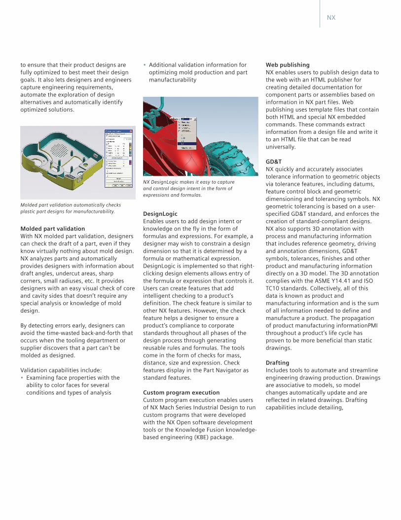
NX Mach Series Industrial Design includes surface textures, lighting effects, and advanced rendering for photorealistic image creation.
Free form shape design
Advanced surface analysis
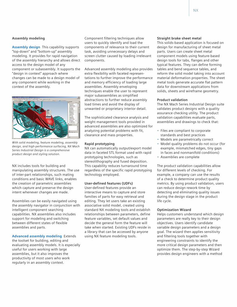
NX Mach Series Industrial Design includes specialized tools for creating organic, styled shapes in precision geometry, using hand sketches as a foundation for modeling.
NX Mach Series Industrial Design
Advanced free form modeling
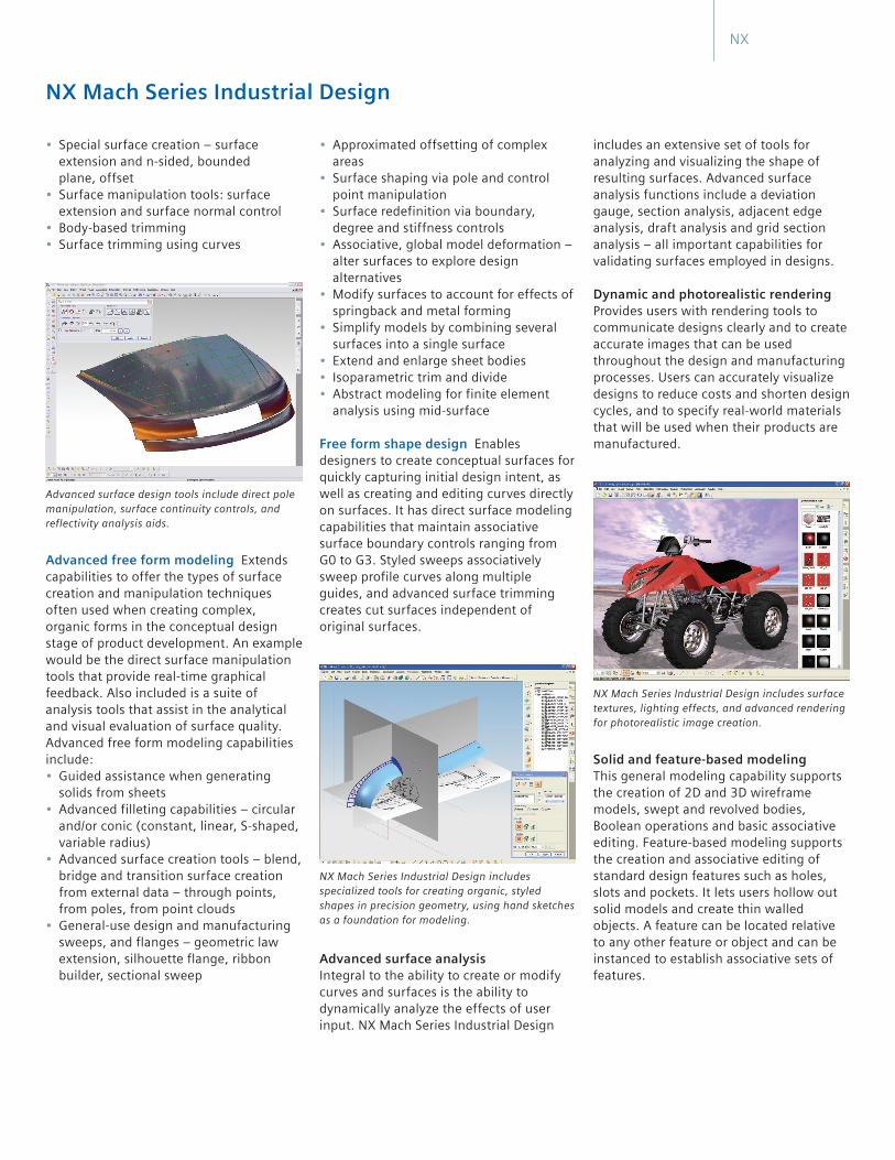
Advanced surface design tools include direct pole manipulation, surface continuity controls, and reflectivity analysis aids.
NX
Straight brake sheet metal
Product validation
Optimization Wizard
Rapid prototyping
User-defined features (UDFs)
Assembly modeling
Assembly design
Advanced assembly modeling
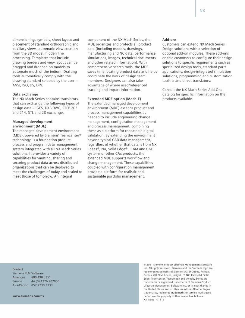
With solid modeling, feature modeling, assembly design, and high-performance surfacing, NX Mach Series Industrial Design is a comprehensive product design and styling solution.
NX
Web publishing
GD&T
Drafting
DesignLogic
Custom program execution
NX DesignLogic makes it easy to capture and control design intent in the form of expressions and formulas.
Molded part validation
Molded part validation automatically checks plastic part designs for manufacturability.
NX
Add-ons
Extended MDE option (Mach-E)
www.siemens.com/nx
Data exchange
Managed development environment (MDE)
NX
NX General PackagingIntelligent tools for automotive mechanical and occupancy packaging
www.siemens.com/nx
NX
Benefits Industry standards and process knowledge are stored for repeatability and standardization
All tools are ready to go out of the box with minimal customization costs
Frees up highly skilled packaging engineers to concentrate on complex packaging problems
Enables rapid evaluation of alternative designs in a unified design environment
Leverages integrated analysis to provide fast feedback on design’s compliance with established standards
Features Automatic geometry creation and integrated compliance checks
Permits early occupancy and mechanical packaging studies
Helps establish key vehicle reference points for configuring and measuring aspects of the interior automobile compartment
Estimates horizontal seat travel for accommodation studies
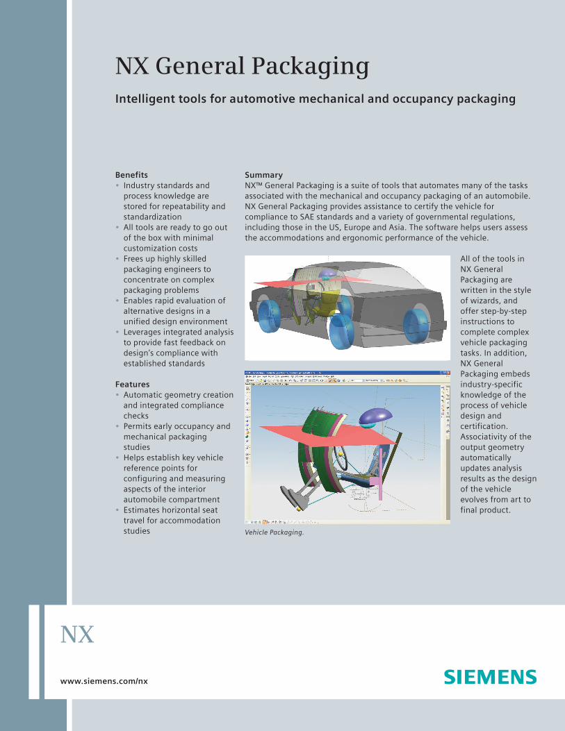
SummaryNX™ General Packaging is a suite of tools that automates many of the tasks associated with the mechanical and occupancy packaging of an automobile. NX General Packaging provides assistance to certify the vehicle for compliance to SAE standards and a variety of governmental regulations, including those in the US, Europe and Asia. The software helps users assess the accommodations and ergonomic performance of the vehicle.
All of the tools in NX General Packaging are written in the style of wizards, and offer step-by-step instructions to complete complex vehicle packaging tasks. In addition, NX General Packaging embeds industry-specific knowledge of the process of vehicle design and certification. Associativity of the output geometry automatically updates analysis results as the design of the vehicle evolves from art to final product.
Vehicle Packaging.
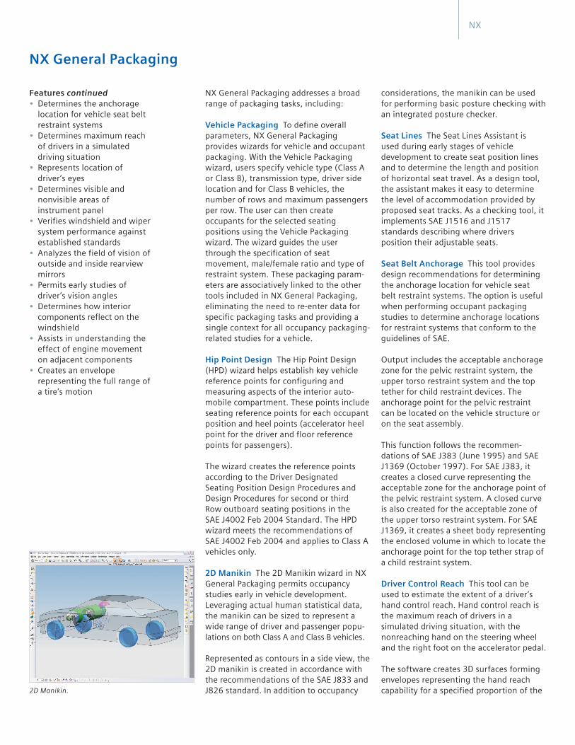
considerations, the manikin can be used for performing basic posture checking with an integrated posture checker.
Seat Lines The Seat Lines Assistant is used during early stages of vehicle development to create seat position lines and to determine the length and position of horizontal seat travel. As a design tool, the assistant makes it easy to determine the level of accommodation provided by proposed seat tracks. As a checking tool, it implements SAE J1516 and J1517 standards describing where drivers position their adjustable seats.
Seat Belt Anchorage This tool provides design recommendations for determining the anchorage location for vehicle seat belt restraint systems. The option is useful when performing occupant packaging studies to determine anchorage locations for restraint systems that conform to the guidelines of SAE.
Output includes the acceptable anchorage zone for the pelvic restraint system, the upper torso restraint system and the top tether for child restraint devices. The anchorage point for the pelvic restraint can be located on the vehicle structure or on the seat assembly.
This function follows the recommen-dations of SAE J383 (June 1995) and SAE J1369 (October 1997). For SAE J383, it creates a closed curve representing the acceptable zone for the anchorage point of the pelvic restraint system. A closed curve is also created for the acceptable zone of the upper torso restraint system. For SAE J1369, it creates a sheet body representing the enclosed volume in which to locate the anchorage point for the top tether strap of a child restraint system.
Driver Control Reach This tool can be used to estimate the extent of a driver’s hand control reach. Hand control reach is the maximum reach of drivers in a simulated driving situation, with the nonreaching hand on the steering wheel and the right foot on the accelerator pedal.
The software creates 3D surfaces forming envelopes representing the hand reach capability for a specified proportion of the
NX General Packaging addresses a broad range of packaging tasks, including:
Vehicle Packaging To define overall parameters, NX General Packaging provides wizards for vehicle and occupant packaging. With the Vehicle Packaging wizard, users specify vehicle type (Class A or Class B), transmission type, driver side location and for Class B vehicles, the number of rows and maximum passengers per row. The user can then create occupants for the selected seating positions using the Vehicle Packaging wizard. The wizard guides the user through the specification of seat movement, male/female ratio and type of restraint system. These packaging param-eters are associatively linked to the other tools included in NX General Packaging, eliminating the need to re-enter data for specific packaging tasks and providing a single context for all occupancy packaging-related studies for a vehicle.
Hip Point Design The Hip Point Design (HPD) wizard helps establish key vehicle reference points for configuring and measuring aspects of the interior auto-mobile compartment. These points include seating reference points for each occupant position and heel points (accelerator heel point for the driver and floor reference points for passengers).
The wizard creates the reference points according to the Driver Designated Seating Position Design Procedures and Design Procedures for second or third Row outboard seating positions in the SAE J4002 Feb 2004 Standard. The HPD wizard meets the recommendations of SAE J4002 Feb 2004 and applies to Class A vehicles only.
2D Manikin The 2D Manikin wizard in NX General Packaging permits occupancy studies early in vehicle development. Leveraging actual human statistical data, the manikin can be sized to represent a wide range of driver and passenger popu-lations on both Class A and Class B vehicles.
Represented as contours in a side view, the 2D manikin is created in accordance with the recommendations of the SAE J833 and J826 standard. In addition to occupancy
NX General Packaging
Features continued Determines the anchorage location for vehicle seat belt restraint systems
Determines maximum reach of drivers in a simulated driving situation
Represents location of driver’s eyes
Determines visible and nonvisible areas of instrument panel
Verifies windshield and wiper system performance against established standards
Analyzes the field of vision of outside and inside rearview mirrors
Permits early studies of driver’s vision angles
Determines how interior components reflect on the windshield
Assists in understanding the effect of engine movement on adjacent components
Creates an envelope representing the full range of a tire’s motion
2D Manikin.
NX
standard or violates it. You can also work in reverse and create criteria geometry (such as sight lines) for an A-pillar, given a target obstruction angle.
This function follows the recommen-dations of SAE J1050 Jan 2003 and EEC 77/649. By using A-Pillar Obstruction during visibility studies, designers can determine the right obstruction angle that conforms to the guidelines of SAE and EEC. The software can generate sight lines given a target obstruction angle and outboard or inboard point of the A-pillar.
Glazing Shade Bands NX General Packaging includes a tool that automates the creation of curves defining the driver glazing shade band. It aids in performing visibility design studies for vehicle packaging during automobile development. The output is curves that mark the shading boundaries.
A glazing shade band is the area immediately adjacent to and below the top edge of a vehicle’s glazing. Light transmission and visibility through the shade band is less than what is required for normal driving. The software provides step-by-step guidance for creating the glazing shade bands. Recommendations in the standards SAE J100 January 2005 are supported.
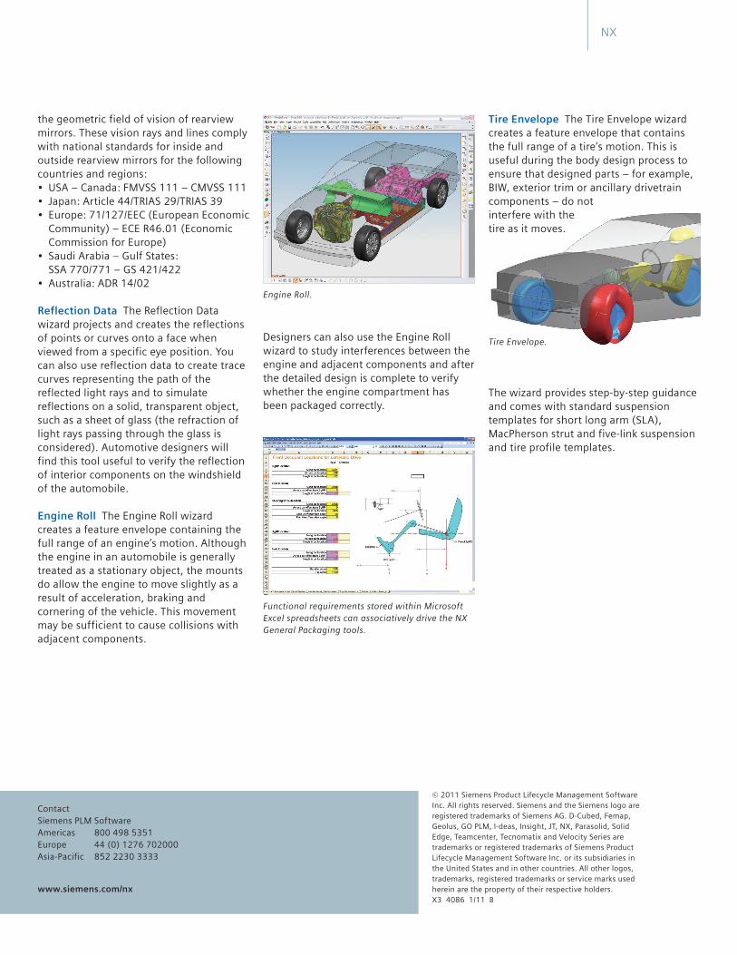
Mirror Certification The Mirror Certification wizard performs analyses on automotive driver and passenger side outside and inside rearview mirrors before certification, or certifies the performance of an existing mirror design. The wizard generates vision rays and lines describing
(European) standards. The program creates the actual windshield wiped area and calculates the percentile of the actual wiped area and checks it against the standard.
The designer specifies the vehicle class, eyellipse, hip point, windshield and wiper system details with step-by-step guidance from the wizard. With this input, the wizard calculates the wiped area and test areas A, B and C and checks whether the results meet the requirements of the standard.
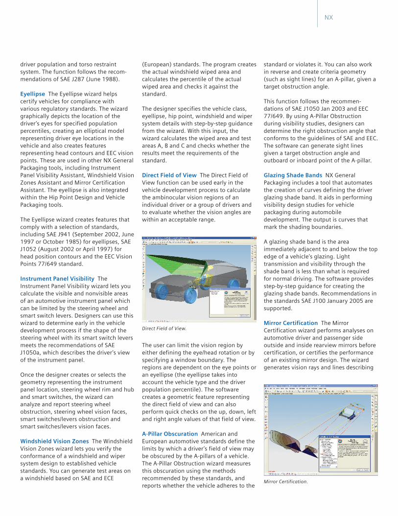
Direct Field of View The Direct Field of View function can be used early in the vehicle development process to calculate the ambinocular vision regions of an individual driver or a group of drivers and to evaluate whether the vision angles are within an acceptable range.
The user can limit the vision region by either defining the eye/head rotation or by specifying a window boundary. The regions are dependent on the eye points or an eyellipse (the eyellipse takes into account the vehicle type and the driver population percentile). The software creates a geometric feature representing the direct field of view and can also perform quick checks on the up, down, left and right angle values of that field of view.
A-Pillar Obscuration American and European automotive standards define the limits by which a driver’s field of view may be obscured by the A-pillars of a vehicle. The A-Pillar Obstruction wizard measures this obscuration using the methods recommended by these standards, and reports whether the vehicle adheres to the
driver population and torso restraint system. The function follows the recom-mendations of SAE J287 (June 1988).
Eyellipse The Eyellipse wizard helps certify vehicles for compliance with various regulatory standards. The wizard graphically depicts the location of the driver’s eyes for specified population percentiles, creating an elliptical model representing driver eye locations in the vehicle and also creates features representing head contours and EEC vision points. These are used in other NX General Packaging tools, including Instrument Panel Visibility Assistant, Windshield Vision Zones Assistant and Mirror Certification Assistant. The eyellipse is also integrated within the Hip Point Design and Vehicle Packaging tools.
The Eyellipse wizard creates features that comply with a selection of standards, including SAE J941 (September 2002, June 1997 or October 1985) for eyellipses, SAE J1052 (August 2002 or April 1997) for head position contours and the EEC Vision Points 77/649 standard.
Instrument Panel Visibility The Instrument Panel Visibility wizard lets you calculate the visible and nonvisible areas of an automotive instrument panel which can be limited by the steering wheel and smart switch levers. Designers can use this wizard to determine early in the vehicle development process if the shape of the steering wheel with its smart switch levers meets the recommendations of SAE J1050a, which describes the driver’s view of the instrument panel.
Once the designer creates or selects the geometry representing the instrument panel location, steering wheel rim and hub and smart switches, the wizard can analyze and report steering wheel obstruction, steering wheel vision faces, smart switches/levers obstruction and smart switches/levers vision faces.
Windshield Vision Zones The Windshield Vision Zones wizard lets you verify the conformance of a windshield and wiper system design to established vehicle standards. You can generate test areas on a windshield based on SAE and ECE
Direct Field of View.
NX
Mirror Certification.
Tire Envelope The Tire Envelope wizard creates a feature envelope that contains the full range of a tire’s motion. This is useful during the body design process to ensure that designed parts – for example, BIW, exterior trim or ancillary drivetrain components – do not interfere with the tire as it moves.
The wizard provides step-by-step guidance and comes with standard suspension templates for short long arm (SLA), MacPherson strut and five-link suspension and tire profile templates.
Designers can also use the Engine Roll wizard to study interferences between the engine and adjacent components and after the detailed design is complete to verify whether the engine compartment has been packaged correctly.
© 2011 Siemens Product Lifecycle Management Software Inc. All rights reserved. Siemens and the Siemens logo are registered trademarks of Siemens AG. D-Cubed, Femap, Geolus, GO PLM, I-deas, Insight, JT, NX, Parasolid, Solid Edge, Teamcenter, Tecnomatix and Velocity Series are trademarks or registered trademarks of Siemens Product Lifecycle Management Software Inc. or its subsidiaries in the United States and in other countries. All other logos, trademarks, registered trademarks or service marks used herein are the property of their respective holders. X3 4086 1/11 B
www.siemens.com/nx
ContactSiemens PLM SoftwareAmericas 800 498 5351Europe 44 (0) 1276 702000Asia-Pacific 852 2230 3333
the geometric field of vision of rearview mirrors. These vision rays and lines comply with national standards for inside and outside rearview mirrors for the following countries and regions:
Community) – ECE R46.01 (Economic Commission for Europe)
SSA 770/771 – GS 421/422
Reflection Data The Reflection Data wizard projects and creates the reflections of points or curves onto a face when viewed from a specific eye position. You can also use reflection data to create trace curves representing the path of the reflected light rays and to simulate reflections on a solid, transparent object, such as a sheet of glass (the refraction of light rays passing through the glass is considered). Automotive designers will find this tool useful to verify the reflection of interior components on the windshield of the automobile.
Engine Roll The Engine Roll wizard creates a feature envelope containing the full range of an engine’s motion. Although the engine in an automobile is generally treated as a stationary object, the mounts do allow the engine to move slightly as a result of acceleration, braking and cornering of the vehicle. This movement may be sufficient to cause collisions with adjacent components.
Engine Roll.
NX
Functional requirements stored within Microsoft Excel spreadsheets can associatively drive the NX General Packaging tools.
Tire Envelope.