nx series - famcocorp.com · nx4 option 0 none 1 hba, al2 2 sv2, sv3 3 ret, rs485 4 rs485, ssr/scr...
TRANSCRIPT
• If there is a possibility of a serious accident due to malfunction or abnormality of this product, install an appropriate protection circuit on the outside.• Since this product is not equipped with a power switch and fuse, install them separately on the outside (fuse rating: 250 V, 0.5 A).• When changing the input sensor (default: K Type), first set the input group (G.In), then set the output group (G.Out), then set the other groups. If you change the data of the input group or the output group after setting other groups, the data of other groups that have already been set will be initialized.• Please supply the rated power voltage, in order to prevent product breakdowns or malfunctions.• To prevent electric shocks and malfunctions, do not supply power until the wiring is completed.
• The product does not have an explosion-proof structure, so avoid using it in places with flammable or explosive gases.• Never disassemble, modify, process, improve or repair this product, as it may cause abnormal operations, electric shocks or fires.• Please disassemble the product after turning OFF the power. Failure to do so may result in electric shocks, product abnormal operations or malfunctions.• Any use of the product other than those specified by the manufacturer may result in personal injury or property damage.• Please use this product after installing it to a panel, because there is a risk of electric shock.
• The input/output terminals are subject to electric shock risk. Never let the input/output terminals come in contact with your body or conductive substances.
• The contents of this manual may be changed without prior notification.• Please make sure that the product specifications are the same as you ordered.• Please make sure that there are no damages or product abnormalities occurred during shipment.• Use the product in a temperature range from 0 to 50 ℃ (max. 40 ° C for close installation) / humidity range from 35 to 85% RH (without condensation)• Please use the product in places where corrosive gases (especially harmful gases, ammonia, etc.) and flammable gases are not generated.• Use the product in places where vibrations and impacts are not applied directly to product body.• Please use the product in places without liquids, oils, chemicals, steam, dust, salt, iron, etc. (pollution degree 1 or 2).• Please do not wipe the product with organic solvents such as alcohol, benzene, etc. (wipe it with neutral detergents).• Please avoid places where large inductive interference, static electricity,magnetic noise are generated.• Please avoid places with heat accumulation caused by direct sunlight, radiant heat, etc.• Please use the product in places with elevation below 2000 m.• When fixing the product to a panel, attach the two brackets on the fixing holes and tighten them with a screwdriver. The fixing torque is about 14.7 N · cm (1.5㎏ · cm).• When water enters, short circuit or fire may occur, so please inspect the product carefully.• For thermocouple input, use the predetermined compensating cable (temperature errors occur when using ordinary cable).• For RTD input, use a cable with small lead wire resistance and without resistance difference among 3 wires (temperature errors occur if the resistance value among 3 wires is different).• Use the input signal line away from power line and load line to avoid the influence of inductive noise.• Input signal line and output signal line should be separated from each other. If separation is not possible, use shield wires for input signal line.• Use a non-grounded sensor for thermocouple (using a grounded sensor may cause malfunctions to the device due to short circuits). When there is a lot of noise from the power, we recommend to use insulation transformer and noise filter. Please install the noise filter to a grounded panel or structure, etc. and make the wiring of noise filter output and product power supply terminal as short as possible.• Tightly twisting the power cables is effective against noise.• If the alarm function is not set correctly, it will not be output in case of abnormal operation, so please check it before operation.
• When replacing the sensor, be sure to turn off the power.• Use an extra relay when the frequency of operation (such as proportional operation, etc.) is high, because connecting the load to the output relay rating without any room shortens the service life. In this case, SSR drive output type is recommended.※ When using electromagnetic switch: set the proportional cycle to at least 20 sec.※ When using SSR: set the proportional cycle to at least 1 sec. ※ Contact output life: Mechanical life min. 10 million times (no load), electrical life min. 100,000 times (250 V a.c. 3 A at rated load)• Although the front part of this product has a IP65 degree of protection, the waterproofing between the product and the panel must be carried out using the attached packing so that the waterproofing is secured, and the packing between the panel and the product does not collapse. (Except for NX1)• Do not wire anything to unused terminals.• Please wire correctly, after checking the polarity of the terminals.• When you install this product to a panel, please use switches or circuit breakers compliant with IEC60947-1 or IEC60947-3.• Please install switches or circuit breakers at close distance for user convenience.• Please specify on the panel that, since switches or circuit breakers are installed, if the switches or circuit breakers are activated, the power will be cut off.• We recommend regular maintenance for the continuous safe use of this product.• Some components of this product may have a lifespan or deteriorate over time.• The warranty period of this product, is 1 year, including its accessories, under normal conditions of use.• When using the heater break alarm, connect the heater power supply and the controller power supply to the same power line.• The preparation period of the contact output is required during power supply. If used as a signal to external interlock circuit, etc. please use a delay relay together.• If the user changes the product in case of malfunctions, the operation may be different due to set parameters differences even if the model name is the same. So, please check the compatibility.• Before using the temperature controller, there may be a temperature deviation between the PV value of the temperature controller and the actual temperature, so please use the product after calibrating the temperature deviation.• The write life of non-volatile memory (EEPROM) is one million times. When configuring the system, please make sure that that the number of times that data are written to non-volatile memory does not exceed one million times.
▍Specifications
● NX4 control output configuration (if the control output is SCR, the HBA can not be used)
■ NX4 suffix codeModel Code Content
(Note)option 1 : OUT1 (terminals ①-②-③) applied as AL1. (when selecting SSR / SCR control output). option 3 : OUT2 (terminals ⑪-⑫) applied as RET.option 4 : OUT2 (terminals ⑪-⑫) applied as SSR/SCR.option 5 : OUT1 (terminals ⑥-⑦) cannot be applied as SV2. option 6 : OUT1 (terminals ⑥-⑦) applied as SV2 (with relay control output).
NX4 □- □ Multi Input/Output Temperature Controller 48(W) X 48(H) ㎜
Size0 Normal type (heating control)1 Heating/cooling control (simultaneous control)2 Heating/cooling control (NX4-20 only)
NX4 option
0 None1 HBA, AL22 SV2, SV33 RET, RS4854 RS485, SSR/SCR5 AL1, AL26 AL1, AL2, SV27 RS485, HBA
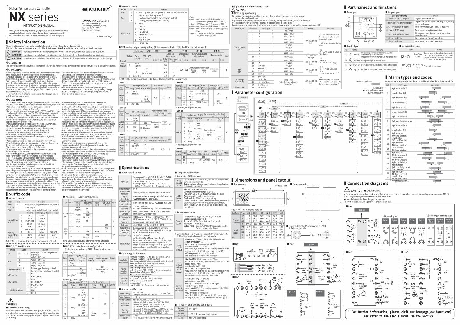
▍Part names and functions■ Front part ■ Display part
Display part name Function① Present value (PV) display Displays present value (PV)
② Set value (SV) / Parameter display Displays set values, various setting parts, setting modes and codes
③ ④ Set value (SV) indicator Turns on when set value 2 or 3 is displayed⑤ Output (OUT) lamp Turns on during output operation
⑥ Auto-tuning display lamp Blinks during auto-tuning / lights up during manual output
⑦ Alarm 1 indicator Turns on during alarm 1 operation⑧ Alarm 2 indicator Turns on during alarm 2 operation
■ Control partNo. Name Content
⑨ Set KeyMove among parameters and data settings, select automatic output amount display.Press and hold for more than 3 sec. to enter simple menu
⑩ Shift Key Change the digit position to be set
⑪ Down Key Decrease set value, select data of each setting mode
⑫ Up Key Increase set value, select data of each setting mode
Name Content
+ Run / Stop
Hot keyThe hot keys can be selected by selecting one between auto-tuning (AT) or manual output (Manu. MV) functions in hot key (Hk.SL) of G.CtL (control group)
+ Enter setting
modeDISP and setting mode
■ Combination keys
■ Input specification
Input type
Thermocouple: K, J, E, T, R, B, S, L, N, U, W, PL2(refer to input signal and measurement range)RTD : Pt 100Ω, KPt 100ΩDC voltage input : 1 - 5 V d.c., -10 - 20 ㎷, 0 - 100 ㎷, 4 - 20 ㎃ (250 Ω with external resistor)
Input sampling cycle 250 ㎳Input display
resolution Basically, below the decimal point of the range
Input impedance
Thermocouple and DC voltage input (㎷): min. 1 ㏁, DC voltage input (V): approx. 1 ㏁
Allowable signal source resistance Thermocouple: max. 250 Ω, DC voltage: max. 2 kΩ
Allowable wiring resistance
RTD: max. 10 Ω/wire (conductor resistance among 3 wires should be same)
Allowable input voltage
Within ±10 V (thermocouple, RTD, DC voltage: ㎷ d.c.)Within ±20 V (DC voltage: V d.c.)
Noise reduction rate
NMRR (normal mode): min. 40 dB (50/60 Hz ±1 %)CMRR (common mode) : min. 120 dB (50/60 Hz ±1 %)
Standard Thermocouple / RTD (KS/IEC/DIN)RJC error ±1.5 ℃ (15 ~ 35 ℃), ±2.0 ℃ (0 ~ 50 ℃)
Input break detection
(BURN-OUT)
Thermocouple: OFF, UP/DOWN Scale selectionRTD : UP Scale (detection current at thermocouple and RTD BURN-OUT: approx. 50 nA)
Measurement accuracy ±0.5 % (FULL SCALE)
Input range
See "Input Signal and Measurement Range". Thermocouple, RTD: can be changed within the range of input signal and measurement range table. DC voltage: min. and max. voltages can be changed within each range. Scaling possible within the range of the measurement range
③ Control output (output type can be selected from relay, current, SSR, heating / cooling type can be set individually.
Relay contact output
Contact capacity: 240 V a.c. 3A, 30 V d.c. 3 A (resistive load)Contact configuration: 1COutput operation: time proportion, ON / OFFProportional period: 1 to 1000 sOutput limit: high limit (OH) and low limit (OL) can be set in the range from 0.0 to 100.0%. Valid also for auto-tuning (AT).ON / OFF Hysteresis: 0 to 100% (full scale)Time resolution: smaller between 0.1% or 10 ms
SSR output(voltage
pulse output)
ON voltage: NX2, 3, 4, 7, 9 approx. min. 12 V d.c.(load resistance min. 600 Ω, limited to 30 ㎃ in short circuit) OFF voltage: max. 0.1 V d.c.Proportional period: 1 ~ 1000 sOutput operation: time proportionalOutput limit: high limit (OH) and low limit (OL) can be set in the range from 0.0 to 100.0%. Valid also for auto-tuning (AT).Time resolution: smaller between 0.1% or 10 ms
Current output
(4 - 20 ㎃)
Current output range : 4 - 20 ㎃ d.c.Load resistance : max. 600 Ω Accuracy : ±0.5% of max. scale (4 - 20 mA range), Resolution : approx. 3,000Output ripple : 0.3% (P-P) or less of the maximum scale (150 Hz)Output update cycle : 250 ㎳ Output operation : continuous PIDOutput limit : high limit (OH) and low limit (OL) can be set in the range from -5.0 to 105.0%. Valid also for auto-tuning (AT).
■ Output specifications① Alarm output (HBA common)
Relay contactoutput
Contact capacity : 240 V a.c. 1 A, 30 V d.c. 1 A (resistive load). Contact configuration : 1aOutput contacts: different according to model specifications (refer to wiring diagram)
Heater breakalarm
1 EA (NX2, NX3, NX4, NX7, NX9)Current measurement range: AC 1 - 50 A(resolution: 0.5 A, ± 5% of maximum scale ± 1 digit). Alarm output: set and use alarm outputDeadband: 0 ~ 100% of max. range settingOthers: available for ON / OFF control or time proportional output (but not for current output and cooling output). When output is ON, the break can not be detected in less than 0.2 sec.
② Retransmission output
Current output
Current output range : 0 - 20 ㎃ d.c., 4 - 20 ㎃ d.c.Load resistance : max. 600 ΩAccuracy : ±0.5% of max 0 ㎃ or 4-20 ㎃ range)Resolution : approx. 3,000Output ripple : max. 0.3% (P-P) of the max. scale (150 Hz) Output update cycle : 250 ㎳
■ Input signal and measuring range
Input signal Selection number Input type Range (℃) Accuracy Remarks
Thermocouple(TC)
1 K *2 -200 ~ 1370
±0.5 % of FS ±1 digit
• FS is from the minimum to the maximum value of each measurable range.
• Digit is the minimum display value
※1 0 ~ 400 ° C range: ± 10.0% of FS ± 1 digit
※2 Max. 0 ℃: ± 1.0% of FS ± 1 digit
※ 3 20 → KPt100 Ω (C1603) ※ 3 21, 22 → Pt100 Ω (IEC751)
※4When current input is used, attach a 250Ω 0.1% resistor to the input signal terminal. "
2 K *2 -199.9 ~ 999.93 J *2 -199.9 ~ 999.94 E *2 -199.9 ~ 999.95 T *2 -199.9 ~ 400.06 R 0 ~ 17007 B *1 0 ~ 18008 S 0 ~ 17009 L *2 -199.9 ~ 900.0
10 N -200 ~ 1300 ±1.0 % of FS ±1 digit
11 U *2 -199.9 ~ 400.0±0.5 % of FS ±1
digit12 W 0 ~ 230013 PlatinelⅡ 0 ~ 1390
RTD(RTD)
20 KSPt100 Ω *3 -199.9 ~ 500.0±0.5 % of FS ±1
digit21 Pt100 Ω *3 -199.9 ~ 640.022 Pt100 Ω *3 -200 ~ 640
DC voltage(VDC/㎷DC)
30 1 - 5 V d.c.
-1999 ~ 9999(Using the scaling function
(SL-H / SL-L))±0.5 % of FS ±1
digit
31 0 - 10 V d.c.32 -10 - 20 ㎷ d.c.33 0 - 100 ㎷ d.c.
Direct current 30 4 - 20 ㎃ d.c. *4
● Measuring input wiring• When wiring the measuring input line, disconnect the controller body and external power supply, as there is a danger of electric shock.• Pay attention to the polarity of the input before connecting. Wrong connection may result in malfunction.• Use shielded wires for input wiring. The shield must be grounded at single-point. • For measuring input signal, wire after leaving room between the power supply circuit and the ground circuit, if possible.
CAUTION
■ Operating environment
Installation environment
Continuous vibration (5 - 14 Hz): peak-to-peak max. 1.2 mm,Continuous vibration (4 - 150 Hz): max. 4.9 ㎨Short-time vibration: 14.7 ㎨, max. 15 seconds (each 3 directions)Shock: 147 ㎨, max. 11 ㎳ (6 directions each 3 times)Panel cutout: refer to "panel cutout"
Normal operating conditions
Ambient temperature: 0 ~ 50 ℃Ambient humidity: 35 ~ 85% RH (without condensation)Magnetic field effect: max. 400 AT / mWarm-up time: min. 30 minutes
Ambient temperature
influence
Thermocouple, voltage input: ± 1 μV / ° C or ± 0.01% / ° C of max. rangeRTD input: max. ± 0.05 Ω / ° CAnalog output: max. ± 0.05% / ℃ of max. range (continuous output)
■ Power specificationsPower voltage 100 - 240 V a.c.
(voltage fluctuation rate : ±10 %) 24 V a.c. / V d.c.
Power frequency 50 - 60 HzPower consumption Max. to 6.0 W, max. 10 VA, 8 VA (NX1)
Insulation resistance
1st terminal - 2nd terminal : min. 500 V d.c. 20 ㏁1st terminal - ground : min. 500 V d.c. 20 ㏁2nd terminal - ground : min. 500 V d.c. 20 ㏁
Dielectric strength
1st terminal - 2nd terminal : 2,300 V a.c. 50/60 Hz for 1 min.1st terminal - ground : 2,300 V a.c. 50/60 Hz for 1 min.2nd terminal - F•G : 1,500 V a.c. 50/60 Hz for 1 min.
Sensor power supply
12 V d.c. ( 20 ㎃ d.c., cannot be used with retransmission output)
■ Transport and storage conditionsStorage
temperature -25 ~ 70 ℃
Storage humidity 5 ~ 95 % RH (without condensation)
Shock Max. 1 m in packaging
▍Parameter configuration
⑤ ⑥ ⑦ ⑧ ⑨ ⑩① ② ③ ④DISP 1
DISP 2DISP 3
1 2 3Power On
1) Operation mode
Process value
Set value
Process value
Out. amount
PVSV
PVSV
Controlgroup
Auto-tuning group
Set valuegroup PID group Alarm
groupRET.
groupCOM.Group
Outputgroup
InputgroupHBA group
For 3 seconds
HOTKEY
For 3 seconds+
Level selection
For 3 seconds
+
Simplemenu
For 3 seconds
For 3 seconds
+
Ramp Atype
Ramp Btype
▍Alarm types and codes(Note): In case of reverse selection, the output will be OFF when the indicator lamp is ON.
△ : Set value -▲ : Minus alarm set value
▲ : Alarm set value
Alarm deadbandCode Alarm type Operation
1 High absolute (NO)
2 Low absolute (NO)
3 High deviation (NO)
4 Low deviation (NO)
5 High deviation (NC)
6 Low deviation (NC)
7 High-Low deviation
8 High-Low deviation range
9 High absolute (NC)
10 Low absolute (NC)
11 High absolute (NO, hold function)
12 Low absolute (NO, hold function)
13 High deviation(NO, hold function)
14 Low deviation(NO, hold function)
15 High deviation (NC, hold function)
16 Low deviation (NC, hold function)
17 High-Low deviation (hold function)
18 High-Low deviat. range (hold function)
19 High absolute (NC, hold function)
20 Low absolute (NC, hold function)
21 Heater break alarm 1 (HBA1)
▍Suffix code
(Note) In NX1-1 □ control output can be selected among 6, 9, 10, and 11.
■ NX1 suffix codeModel Code ContentNX1 - □ □ Multi Input/Output Temperature Controller. 48(W) X 24(H) ㎜Control type
0 Normal type 1 Heating/cooling control (simultaneous control)
Normal type option
Options Heating output Cooling output0 RET Relay -1 None SSR/SCR -2 RS485/RET Relay -3 RS485 SSR/SCR -4 ALM SSR/SCR -5 ALM/RS485 SSR/SCR -
Heating / cooling type option
0 None Relay SSR/SCR1 None SSR/SCR Relay2 RS485 Relay SSR/SCR
■ NX2, 3, 7, 9 suffix codeModel Code Content
NX □- □ □ Multi Input/Output Temperature Controller
Size
2 48(W) X 96(H) ㎜3 96(W) X 48(H) ㎜7 72(W) X 72(H) ㎜9 96(W) X 96(H) ㎜
Control method 0 Normal type (heating control)1 Heating/cooling (simultaneous) control
NX9 option 0 None1 RS485, HBA
NX7 option0 None1 RS485, HBA2 SV2, SV3, HBA
NX2, NX3 option0 SV2, SV31 HBA2 RS485
① Normal type
● NX2,3,7,9 control output configuration (if the control output is SCR, HBA cannot be used.)
② Heating / cooling type
OutputControl output (OUT1) OUT2
DefaultRelay output
SSR / SCR output
Relayoutput
Retransmissionoutput
0 Relay(ON/OFF) -
AL2RET
(Retransmissionoutput)
11 - SSR
2 - SCR (4 - 20 ㎃ d.c.)
3 Relay(PID) -
OutputControl output(OUT1) Cooling (OUT2)
DefaultRelayoutput
SSR / SCRoutput
Relayoutput
SSR / SCR/ RET
4 SSR
AL2
SSR
4
5 SCR(4 - 20 ㎃ d.c.)
6 Relay RET7 SSR
SCR8 SCR(4 - 20 ㎃ d.c.)
9 Relay RET10 SSR
Relay ( AL2 ) RET11 SCR
(4 - 20 ㎃ d.c.)12 Relay
● NX1 control output configuration
Type OutputHeating Cooling
DefaultRelay ⑥-⑦
SSR/SCR ④-⑤
Relay ⑥-⑦
SSR/SCR ④-⑤
Normaltype
0 Relay (ON/OFF) RET
-11
AlarmSSR
2 SCR(4 - 20 ㎃ d.c.)
3 Relay (PID) RET 3
Heating / cooling
type
6Relay
- - SSR6
9 - - SCR10 - SSR Relay -
1011 - SCR
(4 - 20 ㎃ d.c.) Relay -
(Note) Set the control output after checking the suffix code.
● Control output wiringWhen wiring or removing the control output, shut off the controller and external power supply, because there is a risk of electric shock. Use shielded wires for voltage pulse output (SSR) and current output (SCR) wiring.
CAUTION
● Current detector (Model name: CT-50N) ※ Sold separately
▍Dimensions and panel cutout■ Dimensions ■ Panel cutout
H
W
W1
H1
B
A
H2
DD1
H
W
W1
H1
B
A
H2
DD1※ Model: NX4
Classification Type NX1 NX2 NX3 NX4 NX7 NX9
Productdimensions
W 48.0 48.0 96.0 48.0 72.0 96.0H 25.5 96.0 48.0 48.0 72.0 96.0H2 22.0 91.0 44.8 44.8 66.0 91.0D 100.0 100.0 100.0 100.0 100.0 100.2D1 5.8 12.5 12.5 7.4 12.5 12.5
Panelcutout
*1)
W1 45.0 45.0 92.0 45.0 68.0 92.0H1 22.4 92.0 45.0 45.0 68.0 92.0A 65.0 70.0 122.0 60.0 93.0 117.0B 42.4 122.0 70.0 60.0 93.0 117.0
*1) *+0.5 mm tolerance applied [Unit : ㎜]
▍Safety information
DANGER Indicates an imminently hazardous situation which, if not avoided, will result in death or serious injury WARNING Indicates a potentially hazardous situation which, if not avoided, could result in death or serious injury CAUTION Indicates a potentially hazardous situation which, if not avoided, may result in minor injury or properties damage
Please read the safety information carefully before the use, and use the product correctly.The alerts declared in the manual are classified into Danger, Warning and Caution according to their importance
28, Gilpa-ro 71beon-gil, Michuhol-gu, Incheon, KoreaTEL : +82-32-876-4697 http://www.hynux.com
HANYOUNGNUX CO.,LTD
Digital Temperature Controller
NX seriesThank you for purchasing Hanyoung Nux products. Please read the instruction manual carefully before using this product, and use the product correctly. Also, please keep this instruction manual where you can view it any time. MA0613KE180731
INSTRUCTION MANUAL
DANGER
WARNING
CAUTION
※ NX4-01: HBA output is designated as 1-2-3 or 13-14 when selecting 21 for alarm type
Normal type
(heating)
Output
Heating side (OUT1) •NX4-00 NX4-01 NX4-02 NX4-03 NX4-04
DefaultRelay ①-②-③
SSR / SCR⑥-⑦
- Alarms and transformers
External input(DI)
Communication and retransmission Communication
⑬-⑭ ⑪-⑫ Relay⑬-⑭
Transformer⑪-⑫ ⑬-⑭ ⑪-⑫ ⑬-⑭ ⑪-⑫ ⑬-⑭ ⑪-⑫
0 Relay(ON/OFF) -
- -
AL2 -
SV2 SV3Communication
function(RS485)
Retransmission output(RET)
Communication(RS485) - 11 AL1 SSR AL2 CT
2 AL1 SCR(4 - 20 ㎃ d.c.) AL2 -
3 Relay (PID) - AL2 CT
Normal type
(heating)Output
Heating side (OUT1) Alarm outputDefaultRelay ①-②-③ SSR / SCR⑥-⑦ Relay⑬-⑭ Relay⑪-⑫
NX4-05(AL1)(AL2)
0 Relay(ON/OFF) -
AL1 AL2 11 - SSR
2 - SCR(4 - 20 ㎃ d.c.)
3 Relay (PID) -
• NX4–05
Normal type
(heating)Output
OUT1(Heating side ) Alarm outputDefaultRelay ①-②-③ ⑥-⑦ Relay ⑬-⑭ Relay ⑪-⑫
NX4-06(AL1)(AL2)(SV2)
0 Relay(ON/OFF) SV2
AL1 AL2 11 - -2 - -3 Relay (PID) SV2
• NX4–06
Heating/cooling Output Heating side (OUT1) Cooling(OUT2) DefaultRelay ①-②-③ SSR / SCR ⑥-⑦ ⑬-⑭ SSR / SCR⑪-⑫
NX4-10
4 AL1 SSR- SSR
4
5 AL1 SCR (4 - 20 ㎃ d.c.)6 Relay -7 AL1 SSR
- SCR(4 - 20 ㎃ d.c.)8 AL1 SCR (4 - 20 ㎃ d.c.)
9 Relay -※ Heating / cooling control only
• NX4–10
Heating/cooling Output Heating side (OUT1) Cooling (OUT2) DefaultRelay ①-②-③ SSR / SCR ⑥-⑦ ⑬-⑭ ⑪-⑫
NX4-2010 - SSR
AL1 Relay 411 - SCR (4 - 20 ㎃ d.c.)12 Relay -
• NX4–20
Normal type
(heating)Output OUT1 (Heating side ) Communication and
transformers DefaultRelay ①-②-③ SSR / SCR⑥-⑦ ⑬-⑭ ⑪-⑫
NX4-07(RS485)(HBA)
0 Relay(ON/OFF) -
Communicationfunction(RS485)
-
11 AL1 SSR CT
2 AL1 SCR(4 - 20 ㎃ d.c.) -
3 Relay - CT
• NX4–07
Heating/cooling Output
Heating side (OUT1) Communication and cooling output DefaultRelay
①-②-③SSR / SCR
⑥-⑦ ⑬-⑭ SSR / SCR⑪-⑫
NX4-14
4 AL1 SSR
Communicationfunction(RS485)
SSR
4
5 AL1 SCR(4 - 20 ㎃ d.c.)
6 Relay -7 AL1 SSR
SCR(4 - 20 ㎃ d.c.)8 AL1 SCR
(4 - 20 ㎃ d.c.)9 Relay -
※ Heating / cooling control only
• NX4–14
Black: SGRed: RTX(+)White: RTX(-)
■ NX1
■ NX2
■ NX3
● Ground wiring• For grounding, wire with a thick wire of 2 ㎟ or more and class III grounding or more (grounding resistance: max. 100 Ω).• The length of the ground wire should be within 20 m• Ground single-point from the ground terminal.• Do not connect the wiring between ground terminals.
CAUTION
■ NX9
■ NX7
Option 1
Option 2
Option 1
Option 2
Option 3, 4
Option 5, 6
Option 7
1) Normal typeOption NX-10
Option NX-14
Option NX-20
2) Heating / cooling type
Option■ NX4
※ For further information, please visit our homepage(www.hynux.com) and refer to the user's manual in the archive.
▍Connection diagrams
Option
Normal type
⑤ ⑥ ⑦ ⑧ ⑨ ⑩① ② ③ ④
DISP 1DISP 2
DISP 31 2 3
전원투입
1) 운전화면
측정값
설정값
측정값
출력량
PVSV
PVSV
제어그룹 오토튜닝 그룹설정값 설정 그룹 P.I.D그룹 경보그룹 전송그룹 통신그룹 출력그룹 입력그룹히터단선경보그룹
3초간
HOTKEY
3초간+
레벨 선택
3초간+
간편 메뉴
3초간
3초간
+
램프기능종류 A
램프기능종류 B
•본기기의 고장이나 이상이 중대한 사고에 대한 우려가 있는 경우에는 외부에 적절한 보호회로를 설치하고 사고 방지를 도모하여 주십시오.•본기기에는 전원 스위치 및 퓨즈가 부착되어 있지 않으므로 외부에 별도로 설치하여 주십시오 (퓨즈정격 : 250 V 0.5A).•사용 입력 센서(출하시 K Type)를 변경 할 경우 가장 먼저 입력그룹(G.In)을 설정하고 다음으로 출력그룹(G.Out)을 설정한 후 다른 그룹을 설정하십시오, 다른 그룹을 먼저 설정한 후 입력그룹 또는 출력그룹의 데이터를 변경하면 이미 설정되어 있던 다른 그룹의 데이터가 초기화 되므로 절대 주의하여 주십시오.•본기기의 파손방지 및 고장방지를 위하여 정격에 맞는 전원전압을 공급하여 주십시오.
•감전방지 및 기기고장방지를 위하여 모든 배선 작업이 종료될 때까지 전원을 투입하지 마십시오.•방폭구조가 아니므로 가연성,폭발성 가스가 있는 장소에서는 사용하지 마십시오.•본기기는 절대로 분해, 가공, 개선, 수리하지 마십시오. 이상동작, 감전 화재의 위험이 있습니다.•본기기의 탈착은 전원을 OFF한 후 조치하여 주십시오. 감전, 오 동작, 고장의 원인이 됩니다.•제조자가 지정한 방법 이외로 사용 시 에는 상해를 입거나 재산상의 손실이 발생할 수 있습니다.•감전될 위험이 있으므로 통전 중 본기기를 패널에 설치된 상태로 사용하여 주십시오.
입출력 단자는 감전의 위험이 있으니 신체 및 통전물이 절대로 접촉 되지 않도록 하십시오.
• 취급설명서의 내용은 사전 통보 또는 예고 없이 변경될 수 있습니다.•주문하신 사양과 일치하는지 확인 하십시오.•운송 중 파손 및 제품에 이상이 없는지 확인 하십시오.•사용시의 주위온도가 0 ~ 50 ℃(밀착 설치시는 최대 40도)/ 습도35 ~ 85% RH (결로하지 않을 것)의 범위에서 사용하십시오.•부식성 가스 (특히 유해가스, 암모니아 등), 가연성 가스가 발생하지 않는 장소에서 사용하십시오.•본체에 직접 진동, 충격이 가하여지지 않는 장소에서 사용하십시오.•물, 기름, 약품, 증기, 먼지, 염분, 철분 등이 없는 장소(오염등급 1또는2)에서 사용하십시오.•알코올, 벤젠 등 유기 용재로 본기를 닦지 마십시오. (중성세제로 닦아주십시오.)•유도장애가 크고 정전기, 자기 노이즈가 발생하는 장소는 피하여 주십시오.•직사일광 및 복사열 등에 의한 열 축적이 발생하는 장소는 피하여 주십시오.•고도 2,000 m이하의 장소에서 사용하십시오.•계기를 패널에 고정시에는 부속의 고정대(2개)를 고정홀에 걸은 후 드라이버로 고정하여 주시고 고정 토크는 약 14.7 N·㎝(1.5㎏·㎝)입니다.•물이 들어갔을 때에는 누전, 화재의 위험성이 있으므로 필히 점검을 받아주십시오.•열전대 입력의 경우는 소정의 보상도선을 사용하여 주십시오. (일반도선을 사용 할 경우는 온도 오차가 발생됩니다.)•측온 저항체 입력의 경우는 리드선 저항이 작고, 3선간의 저항차가 없는 것을 사용하여 주십시오. (3선간의 저항치가 다를 경우 온도 오차가 발생됩니다)•입력 신호선은 유도 노이즈의 영향을 피하기 위하여 전원선, 동력선, 부하 선 으로부터 피해서 사용하십시오.•입력 신호선과 출력 신호선은 서로 분리하고, 분리가 불가능 할 경우 입력 신호선은 쉴드 (Shield)선을 사용하여 주십시오.•열전대는 비접지 센서를 사용하십시오.(접지센서를 사용 할 경우 누전으로 인한 기기의 오 동작이 발생 할 수 있습니다)•전원으로부터 노이즈가 많은 경우에는 절연트랜스 및 노이즈 필터를 사용 할 것을 장려합니다. 노이즈 필터는 필히 접지되어 있는 패널 등에 부착하고 노이즈 필터 출력측과 계기전원단자의 배선은 짧게 하여 주십시오.•계기 전원선은 촘촘하게 꼬으면 노이즈에 대하여 효과가 있습니다.•경보기능이 바르게 설정되어 있지 않으면 기기 이상시에 출력되지 않으므로 운전 전에 필히 동작을 확인하여 주십시오.
•센서를 교환 할 때는 필히 전원을 OFF하여 주십시오.•비례 동작 등 동작빈도가 높은 경우에 출력릴레이 정격에 여유 없이 부하를 접속하면 수명이 짧아지므로 보조릴레이를 사용하여 주십시오. 이러한 경우에는 SSR구동출력타입을 사용할 것을 장려합니다. ※ 전자 개폐기 사용 시 : 비례주기 20 sec 이상 설정 ※ SSR사용 시 : 비례주기 1 sec이상 설정 ※ 접점출력 수명 : 기계적 수명 1000만회이상 (무부하 시) 전기적 수명 10만회이상 (250 V a.c. 3 A : 정격 부하 시)•본기기의 전면은 IP65에 준한 방수구조 이지만, 계기와 패널간의 방수에 대하여는 첨부된 패킹을 사용하여야 방수성을 확보할수 있으므로 패널과 계기사이에 패킹이 접히지 않게 끼워 주십시오. (NX1은 제외)•사용하지 않는 단자에는 아무것도 결선하지 마십시오•단자의 극성을 확인한 후 배선을 정확하게 연결 바랍니다•본 기기를 패널에 취부시에는 IEC947-1 또는 IEC947-3의 승인된 스위치나 차단기를 사용하십시오•스위치나 차단기는 운전자가 조작이 용이하도록 가까운 거리에 설치하십시오•스위치나 차단기가 설치되어 있으므로 스위치나 차단기를 작동하면 전원이 차단된다는 사항을 패널에 명기하십시오•본기기를 계속적으로 안전하게 사용하기 위하여 정기적인 보수를 권장합니다.•본기기의 탑재부품에는 수명이 있는 것과 경년 변화 하는 것이 있습니다.•부속품을 포함한 본기기의 보증기간은 정상적으로 사용한 경우에 1년입니다.•히타단선 경보 사용시 히타전원과 조절계 전원을 동일 전원선으로 결선하여 주십시오.•전원 투입시에 접점출력의 준비기간이 필요합니다. 외부의 인터록 회로등에 신호로 사용되는 경우에는 지연 릴레이를 병용하여 주십시오.•계기교환 고장 시에 사용자가 미리 소유한 예비기로 교환을 한 경우에는 형명이 동일하여도 설정 파라미터의 차이로 동작이 다를 수 있으므로 호환성을 확인한 후에 실시하여 주십시오•온도 조절기를 사용하시기 전에 온도조절계의 PV값과 실제 온도와 온도편차가 있을 수 있으므로 온도 편차를 보정한 후 사용해 주시기 바랍니다.•비휘발성 메모리(EEPROM)의 쓰기수명은 백만회입니다. 시스템을 구성할 때, 비휘발성 메모리에 데이터를 쓰는 횟수가 백만회를 넘지 않도록 주의가 필요합니다.
주 의
위 험
경 고
사용전에 안전에 관한 주의사항을 잘 읽어 주시고 올바르게 사용하여 주십시요.설명서에 표시된 주의사항은 중요도에 따라 위험, 경고, 주의 심벌로 구분하고 있습니다.
▍안전상 주의사항
위 험 지키지 않을 경우, 사망 또는 중상에 이르는 결과를 낳는 절박한 위험 상황을 표시하고 있습니다.
경 고 지키지 않을 경우, 사망 또는 중상이 발생할 가능성이 예상되는 내용을 표시하고 있습니다.
주 의 지키지 않을 경우, 경미한 상해나 재산상의 손해가 발생할 가능성이 예상되는 내용을 표시하고 있습니다.
인천광역시 미추홀구 길파로 71번길 28고객지원센터 1577-1047http://www.hynux.com
(주)한영넉스
디지털 온도조절계
NX series(주)한영넉스의 제품을 구입하여 주셔서 대단히 감사합니다. 본 제품을 사용하시기 전에 취급설명서를 잘 읽은 후에 올바르게 사용해 주십시오.또한, 취급설명서는 언제라도 볼 수 있는 곳에 반드시 보관해 주십시오.
MA0202KE180731
취급설명서
▍형명구성
▍사양
(주) NX1-1□제품은 제어출력 6, 9, 10, 11 중 선택가능.
■ NX1 형명구성 형 명 코 드 내 용 NX1 - □ □ 멀티 입·출력 온도조절계. 48(W) X 24(H) ㎜
제어종류 0 일반형1 가열/냉각제어(동시)
일반형선택사양
선택사양 가열출력 냉각출력0 RET 릴레이 -1 없음 SSR/SCR -2 RS485/RET 릴레이 -3 RS485 SSR/SCR -4 ALM SSR/SCR -5 ALM/RS485 SSR/SCR -
가열/냉각형선택사양
0 없음 릴레이 SSR/SCR1 없음 SSR/SCR 릴레이2 RS485 릴레이 SSR/SCR
■ NX2, 3, 7, 9 형명구성형 명 코 드 내 용
NX □- □ □ 멀티 입·출력 온도조절계
외형
2 48(W) X 96(H) ㎜
3 96(W) X 48(H) ㎜
7 72(W) X 72(H) ㎜
9 96(W) X 96(H) ㎜
제어방법0 일반형(가열제어)
1 가열/냉각제어(동시)
NX9 선택사양0 없음
1 RS485, HBA
NX7 선택사양
0 없음
1 RS485, HBA
2 SV2, SV3, HBA
NX2, NX3 선택사양
0 SV2, SV3
1 HBA
2 RS485
① 일반형
● NX2,3,7,9 제어출력구성 (제어출력이 SCR일 경우에는 HBA를 사용할수 없습니다.)
② 가열냉각형
출력선택
제어출력(OUT1) OUT2 초기값릴레이출력 SSR / SCR
출력릴레이출력 전송출력
0 릴레이(ON/OFF) -
AL2 RET (전송출력) 11 - SSR
2 - SCR (4 - 20 ㎃ d.c.)
3 릴레이(PID) -
출력선택
제어출력(OUT1) 냉각측 (OUT2) 초기값
릴레이출력
SSR / SCR출력
릴레이출력
SSR / SCR / RET
4 SSR
AL2
SSR
4
5 SCR(4 - 20 ㎃ d.c.)
6 릴레이 RET7 SSR
SCR8 SCR(4 - 20 ㎃ d.c.)
9 릴레이 RET10 SSR
릴레이 ( AL2 ) RET11 SCR
(4 - 20 ㎃ d.c.)12 릴레이
● NX4 제어 출력 구성 (제어 출력이 SCR일 경우에는 HBA를 사용할 수 없습니다.)
■ NX4 형명구성형 명 코 드 내 용
(주)선택사양 1 : OUT1(단자①-②-③)이 AL1로 적용됨. 단,제어출력 SSR/SCR선택시. 선택사양 3 : OUT2(단자⑪-⑫)이 RET로 적용됨. 선택사양 4 : OUT2(단자⑪-⑫)이 SSR/SCR로 적용됨. 선택사양 5 : OUT1(단자⑥-⑦)이 SV2로 적용불가. 선택사양 6 : OUT1(단자⑥-⑦)이 SV2로 적용. 단, 릴레이 제어출력 경우
NX4 □- □ 멀티 입·출력 온도조절계 48(W) X 48(H) ㎜
외형0 일반형(가열제어)1 가열/냉각제어(동시제어)2 가열/냉각제어(NX4-20에 한함)
NX4 선택사양
0 없음1 HBA, AL22 SV2, SV33 RET, RS4854 RS485, SSR/SCR5 AL1, AL26 AL1, AL2, SV27 RS485, HBA
• NX4–05
일반형(가열)
출력선택
가열측(OUT1) 경보출력 초기값릴레이 ①-②-③ SSR / SCR⑥-⑦ 릴레이⑬-⑭ 릴레이⑪-⑫
NX4-05(AL1)(AL2)
0 릴레이(ON/OFF) -
AL1 AL2 11 - SSR
2 - SCR(4 - 20 ㎃ d.c.)
3 릴레이 (PID) -
• NX4–06
일반형(가열)
출력선택
OUT1(가열측) 경보출력 초기값릴레이 ①-②-③ ⑥-⑦ 릴레이 ⑬-⑭ 릴레이 ⑪-⑫
NX4-06(AL1)(AL2)(SV2)
0 릴레이(ON/OFF) SV2
AL1 AL2 11 - -2 - -3 릴레이 (PID) SV2
• NX4–07
일반형(가열)
출력선택
OUT1 (가열측) 통신 및 변류기 초기값릴레이 ①-②-③ SSR / SCR⑥-⑦ ⑬-⑭ ⑪-⑫
NX4-07(RS485)(HBA)
0 릴레이(ON/OFF) -
통신기능(RS485)
-
11 AL1 SSR CT
2 AL1 SCR(4 - 20 ㎃ d.c.) -
3 릴레이 - CT
• NX4–20
가열/냉각
출력선택
가열측 (OUT1) 냉각측 (OUT2) 초기값릴레이 ①-②-③ SSR / SCR ⑥-⑦ ⑬-⑭ ⑪-⑫
NX4-2010 - SSR
AL1 릴레이 411 - SCR (4 - 20 ㎃ d.c.)12 릴레이 -
• NX4–14
가열/냉각
출력선택
가열측(OUT1) 통신 및 냉각출력 초기값릴레이 ①-②-③ SSR / SCR⑥-⑦ ⑬-⑭ SSR / SCR⑪-⑫
NX4-14
4 AL1 SSR
통신기능
(RS485)
SSR
4
5 AL1 SCR(4 - 20 ㎃ d.c.)
6 릴레이 -7 AL1 SSR
SCR(4 - 20 ㎃ d.c.)8 AL1 SCR
(4 - 20 ㎃ d.c.)9 릴레이 -
※ 가열/냉각제어인 경우에 한함
• NX4–10
가열/냉각
출력선택
가열측(OUT1) 냉각측(OUT2) 초기값릴레이 ①-②-③ SSR / SCR ⑥-⑦ ⑬-⑭ SSR / SCR⑪-⑫
NX4-10
4 AL1 SSR- SSR
4
5 AL1 SCR (4 - 20 ㎃ d.c.)6 릴레이 -7 AL1 SSR
- SCR(4 - 20 ㎃d.c.)8 AL1 SCR (4 - 20 ㎃ d.c.)
9 릴레이 -※ 가열/냉각제어인 경우에 한함
③ 제어출력 (출력종류의 선택은 릴레이, 전류, SSR 중 임의로 선택할 수 있으며, 가열/냉각형은 각각 설정가능함.
릴레이 접점출력
접점용량 : 240 V a.c. 3 A, 30 V d.c. 3 A (저항부하)접점구성 : 1C출력동작 : 시간비례, ON/OFF비례주기 : 1 ~ 1000 s출력제한 : 0.0 ~ 100.0 %범위에서 상한 (OH), 하한 (OL) 설정가능, 자동연산 (AT)시에도 유효함ON / OFF 히스테리시스 : 0 ~ 100 % (Full Scale)시간분해능 : 0.1 % 또는 10 ㎳의 작은 쪽
SSR 출력(전압 펄스 출력)
ON전압 : NX2, 3, 4, 7, 9 약 12 V d.c. 이상 (부하저항 600 Ω이상, 단락시 약 30 ㎃의 전류에 제한)OFF전압 : 0.1 V d.c.이하비례주기 : 1 ~ 1000 s출력동작 : 시간비례출력제한 : 0.0 ~ 100.0 %의 범위에서 상한(OH), 하한(OL)설정가능, 자동연산(AT)시에도 유효함시간분해능 : 0.1 % 또는 10 ㎳의 작은 쪽
전류 출력(4 - 20 ㎃)
전류출력범위 : 4 - 20 ㎃ d.c.부하저항 : 600 Ω이하정 도 : 최대스케일의 ±0.5 % (4 - 20 ㎃의 범위), 분해능 : 약 3,000출력리플 : 최대스케일의 0.3 %(P-P)이하 (150 Hz)출력갱신주기 : 250 ㎳ 출력동작 : 연속 PID출력제한 : -5.0 ~ 105.0 %의 범위에서 상한(OH), 하한(OL)설정가능, 자동연산(AT)시에도 유효함
■ 출력사양① 경보출력 (HBA공통)
릴레이 접점출력
접점용량 : 240 V a.c. 1 A, 30 V d.c. 1 A (저항부하)접점구성 : 1a출력점수 : 모델별 사양에 따라 상이함. (결선도 참조)
히터 단선경보
점 수 : 1점 (NX2, NX3, NX4, NX7, NX9)전류측정범위 : AC 1 - 50 A (분해능 : 0.5 A, 최대스케일의 ±5 % ±1digit)경보출력 : 경보출력 중 임의로 지정하여 사용데드밴드 : 최대레인지의 0 ~ 100 %설정기 타 : · ON/OFF제어 또는 시간비례출력에 사용가능 (단, 전류출력, 냉각출력에는 사용불가) · 출력 ON시 0.2초 이하에서는 단선검출 불가
② 전송출력
전류출력
전류출력범위 : 0 - 20 ㎃ d.c., 4 - 20 ㎃ d.c.부하저항 : 600 Ω이하정 도 : 최대스케일의 ±0.5 % (0 - 20 ㎃ 또는 4 - 20 ㎃의 범위)분 해 능 : 약 3,000출력리플 : 최대스케일의 0.3 % (P-P) 이하 (150 Hz)출력갱신주기 : 250 ㎳
■ 입력신호와 측정레인지
입력신호 선택번호 입력종류 레인지 (℃) 정 도 비 고
열전대(T.C)
1 K *2 -200 ~ 1370
±0.5 % of FS ±1 digit
• FS 는 각 레인지 측정 가능범위의 최소치에서 최대치까지.
•Digit는 최소표시치
※1 0 ~ 400 ℃ 의 범위: ±10.0 % of FS ±1 digit
※2 0℃ 이하: ±1.0 % of FS ±1 digit
※3 20번 → KPt100 Ω (C1603) ※3 21번, 22번 → Pt100 Ω (IEC751)
※4 전류입력을 사용할 경우에는 입력신호 단자에 250Ω 0.1 % 저항을 부착하여 사용하여 주십시오."
2 K *2 -199.9 ~ 999.93 J *2 -199.9 ~ 999.94 E *2 -199.9 ~ 999.95 T *2 -199.9 ~ 400.06 R 0 ~ 17007 B *1 0 ~ 18008 S 0 ~ 17009 L *2 -199.9 ~ 900.0
10 N -200 ~ 1300 ±1.0 % of FS ±1 digit
11 U *2 -199.9 ~ 400.0±0.5 % of FS ±1
digit12 W 0 ~ 230013 PlatinelⅡ 0 ~ 1390
측온저항체(RTD)
20 KSPt100 Ω *3 -199.9 ~ 500.0±0.5 % of FS ±1
digit21 Pt100 Ω *3 -199.9 ~ 640.022 Pt100 Ω *3 -200 ~ 640
직류전압(VDC/㎷DC)
30 1 - 5 V d.c.
-1999 ~ 9999(스케일링기능(SL-H/SL-L)을
이용)±0.5 % of FS ±1
digit
31 0 - 10 V d.c.32 -10 - 20 ㎷ d.c.33 0 - 100 ㎷ d.c.
직류전류 30 4 - 20 ㎃ d.c. *4
● 측정 입력 배선•측정 입력 선을 배선 할 때는 반드시 조절계 본체 및 외부 공급전원을 끊어 주십시오, 감전의 위험이 있습니다•입력의 극성에 주의하여 접속하여 주십시오, 틀리게 접속하면 본체 고장의 원인이 됩니다•입력의 배선은 SHIELD 처리되어 있는 것을 사용하여 주십시오. 또 SHIELD는 1점으로 접지하여 주십시오•측정 입력신호는 전원회로와 접지회로로 부터 가능하면 사이를 두고 배선하여 주십시오
주 의
■ 동작환경
설치환경
연속진동 (5 - 14 Hz) : 전진폭 1.2 ㎜이하, 연속진동 (4 - 150 Hz) : 4.9 ㎨ 이하단시간 진동 : 14.7 ㎨ , 15초 이하 (각 3방향)충 격 : 147 ㎨ , 11 ㎳ 이하 (6방향 각3회)패널가공치수 : 패널가공치수도 참조
정상 동작 조건
주위온도 : 0 ~ 50 ℃주위습도 : 35 ~ 85 %RH (단, 결로하지 않을 것)자계의 영향 : 400 AT/m이하예열시간 (Warm-up Time) : 30분 이상
주위 온도의 영향
열전대, 전압입력 : ±1 μV / ℃ 또는 최대레인지의 ±0.01 % / ℃측온저항체 입력 : ±0.05 Ω/ ℃ 이하아나로그 (Analog)출력 : 최대레인지의 ±0.05 % / ℃이하 (연속출력)
■ 전원사양전원전압 100 - 240 V a.c. (전압변동율 : ±10 %) 24 V a.c. / V d.c.
전원주파수 50 - 60 Hz소비전력 최대 6.0 W, 10 VA이하, 8 VA (NX1)
절연저항1차단자 - 2차단자 사이 : 500 V d.c. 20 ㏁이상1차단자 - GROUND 사이 : 500 V d.c. 20 ㏁이상2차단자 - GROUND 사이 : 500 V d.c. 20 ㏁이상
내 전 압1차단자 - 2차단자 사이 : 2,300 V a.c. 50/60 Hz 1분간1차단자 - GROUND 사이 : 2,300 V a.c. 50/60 Hz 1분간2차단자 - F•G 사이 : 1,500 V a.c. 50/60 Hz 1분간
센서용전원 12 V d.c. ( 20 ㎃ d.c. 단, 전송출력 사용시에는 사용할 수 없습니다.)
■ 수송·보관조건보관온도 -25 ~ 70 ℃보관습도 5 ~ 95 % RH (단, 결로하지 않을 것)충 격 포장상태에서 1 m이하
▍파라미터 구성
▍경보 종류 및 코드(주의) : 역접선택시에는 표시램프가 ON되었을때 출력이 OFF로 동작하므로 주의를 요함.
△ : 설정값, -▲ : 마이너스 경보설정값
▲ : 경보설정값
경보 불감대 코드 경보종류 동 작 도
1 상한절대 (정접)
2 하한절대 (정접)
3 상한편차 (정접)
4 하한편차 (정접)
5 상한편차 (역접)
6 하한편차 (역접)
7 상·하한편차
8 상·하한편차 범위내
9 상한절대 (역접)
10 하한절대 (역접)
11 상한절대 (정접, 홀드기능)
12 하한절대 (정접, 홀드기능)
13 상한편차 (정접, 홀드기능)
14 하한편차 (정접, 홀드기능)
15 상한편차 (역접, 홀드기능)
16 하한편차 (역접, 홀드기능)
17 상·하한편차 (홀드기능)
18 상·하한편차 범위내 (홀드기능)
19 상한절대 (역접, 홀드기능)
20 하한절대 (역접, 홀드기능)
21 히타단선경보 1 (HBA1)
● NX1 제어출력구성
종 류 출력선택
가열측 냉각측 초기값
릴레이⑥-⑦
SSR/SCR ④-⑤
릴레이⑥-⑦
SSR/SCR ④-⑤
일반형
0 릴레이(ON/OFF) RET
- 11 경보(ALARM)
SSR
2 SCR(4 - 20 ㎃ d.c.)
3 릴레이(PID) RET 3
가열/
냉각형
6릴레이
- - SSR6
9 - - SCR10 - SSR 릴레이 -
1011 - SCR
(4 - 20 ㎃ d.c.) 릴레이 -
(주) 형명구성을 확인 후 제어출력을 설정하여 주십시오.
● 제어출력의 배선제어출력을 배선 또는 제거 하는 경우는 반드시 조절계 본체 및 외부공급전원을 차단하여 주십시오,감전의 위험이 있습니다. 전압 펄스출력(SSR), 전류출력(SCR)의 배선에는 Shield선을 사용하여 주십시오.주 의
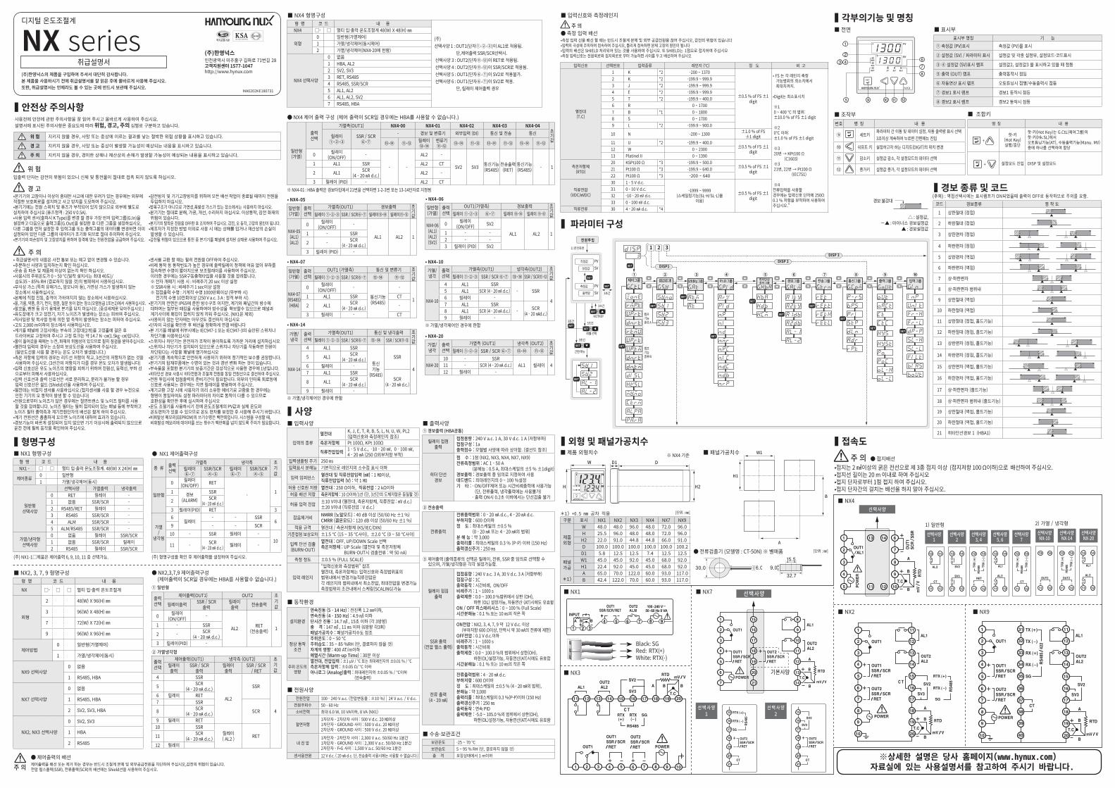
▍각부의기능 및 명칭■ 전면 ■ 표시부
표시부 명칭 기 능① 측정값 (PV)표시 측정값 (PV)를 표시
② 설정값 (SV) / 파라미터 표시 설정값 및 각종 설정부, 설정모드·코드표시
③ ④ 설정값 (SV)표시 램프 설정값2, 설정값3 을 표시하고 있을 때 점등
⑤ 출력 (OUT) 램프 출력동작시 점등
⑥ 자동연산 표시 램프 오토튜닝시 점멸/수동출력시 점등
⑦ 경보1 표시 램프 경보1 동작시 점등
⑧ 경보2 표시 램프 경보2 동작시 점등
■ 조작부번호 명 칭 내 용
⑨ 세트키파라미터 간 이동 및 데이터 설정, 자동 출력량 표시 선택 3초이상 계속하여 누르면 간편메뉴 진입
⑩ 쉬프트 키 설정하고자 하는 디지트(DIGIT)의 위치 변경
⑪ 감소키 설정값 감소, 각 설정모드의 데이터 선택
⑫ 증가키 설정값 증가, 각 설정모드의 데이터 선택
명 칭 내 용
+ 핫-키
(Hot Key)실행/중단
핫-키(Hot Key)는 G.CtL(제어그룹)의 핫-키(Hk.SL)에서 오토튜닝기능(AT), 수동출력기능(Manu. MV)중에 하나를 선택하여 할당
+ 설정모드 진입 DISP 및 설정모드
■ 조합키
[단위 : ㎜]● 전류검출기 (모델명 : CT-50N) ※ 별매품
▍외형 및 패널가공치수■ 제품 외형치수 ■ 패널가공치수
H
W
W1
H1
B
A
H2
DD1
H
W
W1
H1
B
A
H2
DD1※ NX4 기준
구분 표시 NX1 NX2 NX3 NX4 NX7 NX9
제품외형
W 48.0 48.0 96.0 48.0 72.0 96.0H 25.5 96.0 48.0 48.0 72.0 96.0H2 22.0 91.0 44.8 44.8 66.0 91.0D 100.0 100.0 100.0 100.0 100.0 100.2D1 5.8 12.5 12.5 7.4 12.5 12.5
패널가공
*1)
W1 45.0 45.0 92.0 45.0 68.0 92.0H1 22.4 92.0 45.0 45.0 68.0 92.0A 65.0 70.0 122.0 60.0 93.0 117.0B 42.4 122.0 70.0 60.0 93.0 117.0
*1) +0.5 mm 공차 적용 [단위 : ㎜]
※ NX4-01 : HBA 출력은 경보타입에서 21번을 선택하면 1-2-3번 또는 13-14단자로 지정됨
일반형(가열)
출력선택
가열측(OUT1) NX4-00 NX4-01 NX4-02 NX4-03 NX4-04초기값
릴레이①-②-③
SSR / SCR⑥-⑦
- 경보 및 변류기 외부입력 (DI) 통신 및 전송 통신
⑬-⑭ ⑪-⑫ 릴레이⑬-⑭
변류기⑪-⑫ ⑬-⑭ ⑪-⑫ ⑬-⑭ ⑪-⑫ ⑬-⑭ ⑪-⑫
0 릴레이(ON/OFF) -
- -
AL2 -
SV2 SV3 통신기능(RS485)
전송출력(RET)
통신기능(RS485) - 11 AL1 SSR AL2 CT
2 AL1 SCR(4 - 20 ㎃ d.c.) AL2 -
3 릴레이 (PID) - AL2 CT
■ 입력사양
입력의 종류
열전대 K, J, E, T, R, B, S, L, N, U, W, PL2(입력신호와 측정레인지 참조)
측온저항체 Pt 100Ω, KPt 100Ω
직류전압입력 1 - 5 V d.c., -10 - 20 ㎷, 0 - 100 ㎷, 4 - 20 ㎃ (250 Ω외부저항 부착)
입력샘플링 주기 250 ㎳입력표시 분해능 기본적으로 레인지의 소수점 표시 이하
입력 임피던스 열전대 및 직류전압입력 (㎷) : 1 ㏁이상, 직류전압입력 (V) : 약 1 ㏁
허용 신호원 저항 열전대 : 250 Ω이하, 직류전압 : 2 kΩ이하허용 배선 저항 측온저항체 : 10 Ω이하/1선 (단, 3선간의 도체저항은 동일할 것)
허용 입력 전압 ±10 V이내 (열전대, 측온저항체, 직류전압 : ㎷ d.c.)±20 V이내 (직류전압 : V d.c.)
잡음제거비 NMRR (노말모드) : 40 dB 이상 (50/60 Hz ±1 %)CMRR (콤몬모드) : 120 dB 이상 (50/60 Hz ±1 %)
적용 규격 열전대 / 측온저항체 (KS/IEC/DIN)기준접점 보상오차 ±1.5 ℃ (15 ~ 35 ℃사이), ±2.0 ℃ (0 ~ 50 ℃사이)
입력 단선 검출(BURN-OUT)
열전대 : OFF, UP/DOWN Scale 선택측온저항체 : UP Scale (열전대 및 측온저항체 BURN-OUT시 검출전류 : 약 50 nA)
측정 정도 ±0.5 % (FULL SCALE)
입력 레인지
“입력신호와 측정범위” 참조열전대, 측온저항체는 입력신호와 측정범위표의 범위내에서 변경가능직류전압은 각 레인지의 범위내에서 최소전압, 최대전압을 변경가능측정범위의 조건내에서 스케링(SCALING)가능
▍접속도
Black: SGRed: RTX(+)White: RTX(-)
■ NX1
■ NX2
■ NX3
● 접지배선•접지는 2 ㎟이상의 굵은 전선으로 제 3종 접지 이상 (접지저항 100 Ω이하)으로 배선하여 주십시오.•접지선 길이는 20 m 이내로 하여 주십시오•접지 단자로부터 1점 접지 하여 주십시오.•접지 단자간의 걸치는 배선을 하지 말아 주십시오.
주 의
■ NX9
선택사양■ NX7
선 택 사 양 1
선 택 사 양 2
선택사양 1
선택사양 2
선택사양 3, 4
선택사양 5, 6
선택사양 7
1) 일반형선택사양 NX-10
선택사양 NX-14
선택사양 NX-20
2) 가열 / 냉각형
선택사양■ NX4
※상세한 설명은 당사 홈페이지(www.hynux.com) 자료실에 있는 사용설명서를 참고하여 주시기 바랍니다.