nxt air motor - graco€¦ · instructions/parts nxt® air motor 312796r en for use with high...
TRANSCRIPT

Instructions/Parts
NXT® Air Motor 312796REN
For use with high performance finishing and coating pumps in hazardous or non-hazardous locations. For professional use only.
Models M02xxx, M04xxx, M07xxx, M12xxx, M18xxx, and M34xxx
100 psi (0.7 MPA, 7.0 bar) Maximum Working Pressure
See page 3 for model information.
Important Safety InstructionsRead all warnings and instructions in this manual. For complete warnings and instructions see your pump or package manual. Hazard symbols refer to specific procedure risks. Save all instructions.
ti11838a
Related Manuals
2 312796R
ContentsRelated Manuals . . . . . . . . . . . . . . . . . . . . . . . . . . . 2Warnings . . . . . . . . . . . . . . . . . . . . . . . . . . . . . . . . . 3Models . . . . . . . . . . . . . . . . . . . . . . . . . . . . . . . . . . . 5Component Identification . . . . . . . . . . . . . . . . . . . . 6
Grounding . . . . . . . . . . . . . . . . . . . . . . . . . . . . . . 7Accessories . . . . . . . . . . . . . . . . . . . . . . . . . . . . . 7
Troubleshooting . . . . . . . . . . . . . . . . . . . . . . . . . . . 8Repair . . . . . . . . . . . . . . . . . . . . . . . . . . . . . . . . . . . . 9
Preventive Maintenance Schedule . . . . . . . . . . . 9Pressure Relief Procedure . . . . . . . . . . . . . . . . . 9Repair Air Valve . . . . . . . . . . . . . . . . . . . . . . . . . 9Replace Pilot Valves . . . . . . . . . . . . . . . . . . . . . 13Repair Air Motor . . . . . . . . . . . . . . . . . . . . . . . . 13
Parts . . . . . . . . . . . . . . . . . . . . . . . . . . . . . . . . . . . . 16Air Motor Parts — All Models . . . . . . . . . . . . . . . . 17Air Valve Parts . . . . . . . . . . . . . . . . . . . . . . . . . . . . 19Kits and Accessories . . . . . . . . . . . . . . . . . . . . . . 21Dimensions . . . . . . . . . . . . . . . . . . . . . . . . . . . . . . 22Mounting Hole Diagrams . . . . . . . . . . . . . . . . . . . 23Technical Data . . . . . . . . . . . . . . . . . . . . . . . . . . . . 25Graco Standard Warranty . . . . . . . . . . . . . . . . . . . 26Graco Information . . . . . . . . . . . . . . . . . . . . . . . . . 26
Related Manuals
Manual Description
312792 Merkur Displacement Pump
312793 Merkur Bellows Displacement Pump
312794 Merkur Pump Assembly
312795 Merkur Bellows Pump Assembly
312797 Merkur Spray Packages, AA and Airless, Ambient
312798 Merkur Electrostatic Spray Packages
312799 Merkur Bellows Spray Packages, AA and Airless
313255 Merkur Heated Spray Packages

Warnings
312796R 3
WarningsThe following warnings are for the setup, use, grounding, maintenance, and repair of this equipment. The exclama-tion point symbol alerts you to a general warning and the hazard symbol refers to procedure-specific risk. Refer back to these warnings. Additional, product-specific warnings may be found throughout the body of this manual where applicable.
FIRE AND EXPLOSION HAZARDFlammable fumes, such as solvent and paint fumes, in work area can ignite or explode. To help prevent fire and explosion:• Use equipment only in well ventilated area.• Eliminate all ignition sources; such as pilot lights, cigarettes, portable electric lamps, and plastic drop
cloths (potential static arc). • Keep work area free of debris, including solvent, rags and gasoline.• Do not plug or unplug power cords, or turn power or light switches on or off when flammable fumes are
present.• Ground all equipment in the work area. See Grounding instructions.• Use only grounded hoses.• Hold gun firmly to side of grounded pail when triggering into pail.• If there is static sparking or you feel a shock, stop operation immediately. Do not use equipment until
you identify and correct the problem.• Keep a working fire extinguisher in the work area.
EQUIPMENT MISUSE HAZARDMisuse can cause death or serious injury.• Do not operate the unit when fatigued or under the influence of drugs or alcohol.• Do not exceed the maximum working pressure or temperature rating of the lowest rated system com-
ponent. See Technical Data in all equipment manuals.• Use fluids and solvents that are compatible with equipment wetted parts. See Technical Data in all
equipment manuals. Read fluid and solvent manufacturer’s warnings. For complete information about your material, request MSDS forms from distributor or retailer.
• Check equipment daily. Repair or replace worn or damaged parts immediately with genuine manufac-turer’s replacement parts only.
• Do not alter or modify equipment.• Use equipment only for its intended purpose. Call your distributor for information.• Route hoses and cables away from traffic areas, sharp edges, moving parts, and hot surfaces.• Do not kink or over bend hoses or use hoses to pull equipment.• Keep children and animals away from work area.• Comply with all applicable safety regulations.
SKIN INJECTION HAZARDHigh-pressure fluid from gun, hose leaks, or ruptured components will pierce skin. This may look like just a cut, but it is a serious injury that can result in amputation. Get immediate surgical treatment.• Do not point gun at anyone or at any part of the body.• Do not put your hand over the spray tip.• Do not stop or deflect leaks with your hand, body, glove, or rag.• Do not spray without tip guard and trigger guard installed.• Engage trigger lock when not spraying.• Follow Pressure Relief Procedure in this manual, when you stop spraying and before cleaning,
checking, or servicing equipment.
WARNINGWARNINGWARNINGWARNING

Warnings
4 312796R
PRESSURIZED EQUIPMENT HAZARDFluid from the gun/dispense valve, leaks, or ruptured components can splash in the eyes or on skin and cause serious injury.• Follow Pressure Relief Procedure in this manual, when you stop spraying and before cleaning,
checking, or servicing equipment. • Tighten all fluid connections before operating the equipment.• Check hoses, tubes, and couplings daily. Replace worn or damaged parts immediately.
MOVING PARTS HAZARDMoving parts can pinch or amputate fingers and other body parts.• Keep clear of moving parts.• Do not operate equipment with protective guards or covers removed.• Pressurized equipment can start without warning. Before checking, moving, or servicing equipment,
follow the Pressure Relief Procedure in this manual. Disconnect power or air supply.
PERSONAL PROTECTIVE EQUIPMENTYou must wear appropriate protective equipment when operating, servicing, or when in the operating area of the equipment to help protect you from serious injury, including eye injury, inhalation of toxic fumes, burns, and hearing loss. This equipment includes but is not limited to:• Protective eyewear • Clothing and respirator as recommended by the fluid and solvent manufacturer• Gloves• Hearing protection
WARNINGWARNINGWARNINGWARNING
Models
312796R 5
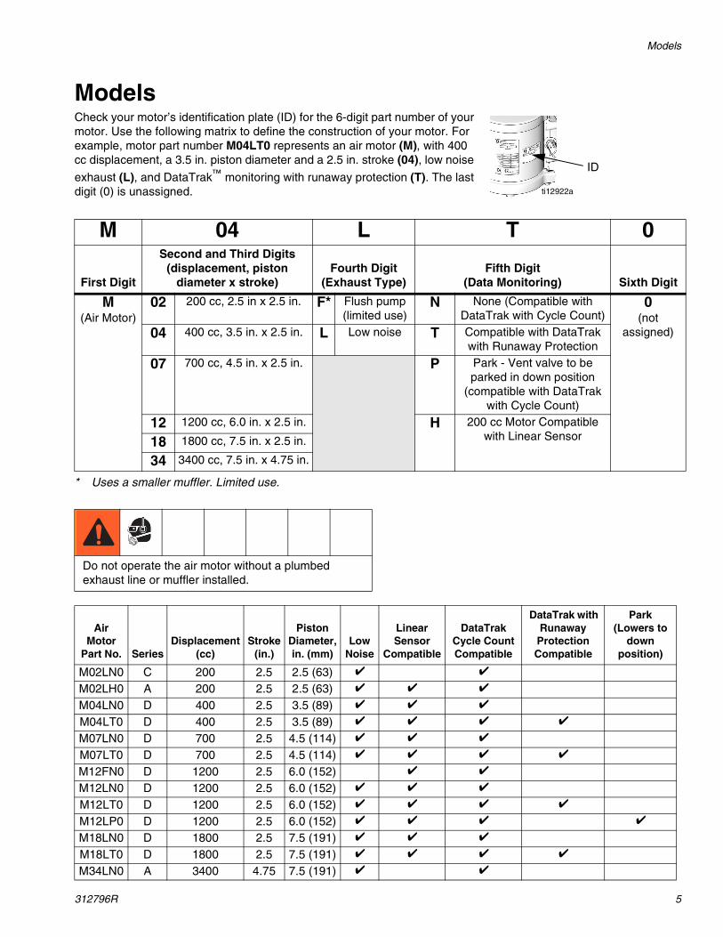
ModelsCheck your motor’s identification plate (ID) for the 6-digit part number of your motor. Use the following matrix to define the construction of your motor. For example, motor part number M04LT0 represents an air motor (M), with 400 cc displacement, a 3.5 in. piston diameter and a 2.5 in. stroke (04), low noise
exhaust (L), and DataTrak™ monitoring with runaway protection (T). The last digit (0) is unassigned.
* Uses a smaller muffler. Limited use.
ti12922a
ID
M 04 L T 0
First Digit
Second and Third Digits (displacement, piston
diameter x stroke)Fourth Digit
(Exhaust Type)Fifth Digit
(Data Monitoring) Sixth Digit
M(Air Motor)
02 200 cc, 2.5 in x 2.5 in. F* Flush pump(limited use)
N None (Compatible with DataTrak with Cycle Count)
0(not
assigned)04 400 cc, 3.5 in. x 2.5 in. L Low noise T Compatible with DataTrak with Runaway Protection
07 700 cc, 4.5 in. x 2.5 in. P Park - Vent valve to be parked in down position
(compatible with DataTrak with Cycle Count)
12 1200 cc, 6.0 in. x 2.5 in. H 200 cc Motor Compatible with Linear Sensor18 1800 cc, 7.5 in. x 2.5 in.
34 3400 cc, 7.5 in. x 4.75 in.
Do not operate the air motor without a plumbed exhaust line or muffler installed.
Air Motor
Part No. SeriesDisplacement
(cc)Stroke
(in.)
Piston Diameter,in. (mm)
Low Noise
Linear Sensor
Compatible
DataTrak Cycle Count Compatible
DataTrak with Runaway
ProtectionCompatible
Park (Lowers to
down position)
M02LN0 C 200 2.5 2.5 (63) ✔ ✔
M02LH0 A 200 2.5 2.5 (63) ✔ ✔ ✔
M04LN0 D 400 2.5 3.5 (89) ✔ ✔ ✔
M04LT0 D 400 2.5 3.5 (89) ✔ ✔ ✔ ✔
M07LN0 D 700 2.5 4.5 (114) ✔ ✔ ✔
M07LT0 D 700 2.5 4.5 (114) ✔ ✔ ✔ ✔
M12FN0 D 1200 2.5 6.0 (152) ✔ ✔
M12LN0 D 1200 2.5 6.0 (152) ✔ ✔ ✔
M12LT0 D 1200 2.5 6.0 (152) ✔ ✔ ✔ ✔
M12LP0 D 1200 2.5 6.0 (152) ✔ ✔ ✔ ✔
M18LN0 D 1800 2.5 7.5 (191) ✔ ✔ ✔
M18LT0 D 1800 2.5 7.5 (191) ✔ ✔ ✔ ✔
M34LN0 A 3400 4.75 7.5 (191) ✔ ✔
Component Identification
6 312796R
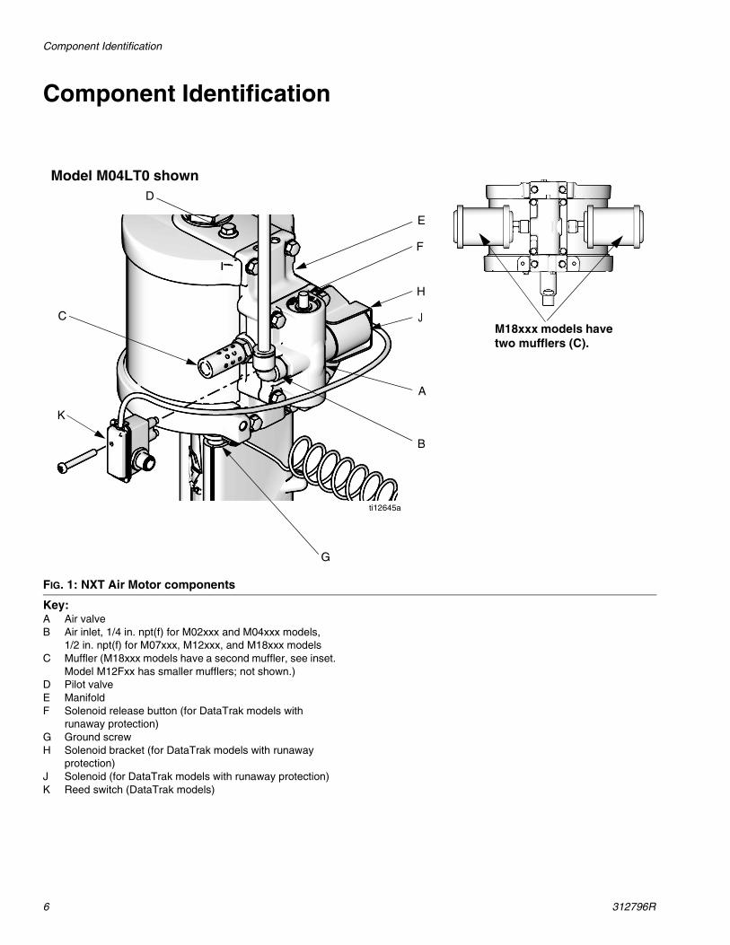
Component Identification
Key:A Air valveB Air inlet, 1/4 in. npt(f) for M02xxx and M04xxx models,
1/2 in. npt(f) for M07xxx, M12xxx, and M18xxx modelsC Muffler (M18xxx models have a second muffler, see inset.
Model M12Fxx has smaller mufflers; not shown.)D Pilot valveE ManifoldF Solenoid release button (for DataTrak models with
runaway protection)G Ground screwH Solenoid bracket (for DataTrak models with runaway
protection)J Solenoid (for DataTrak models with runaway protection)K Reed switch (DataTrak models)
FIG. 1: NXT Air Motor components
A
B
C
D
F
G
H
J
K
ti12645a
E
Model M04LT0 shown
M18xxx models have two mufflers (C).

Component Identification
312796R 7
Grounding
See FIG. 2. Verify that the ground screw (GS) is attached and tightened securely to the air motor. Con-nect the other end of the ground wire (U) to a true earth ground.
Accessories
Bleed-type master air valve
• Required in your system to relieve air trapped between it and the air motor when the valve is closed.
• Be sure the valve is easily accessible from the pump and located downstream from the air regula-tor.
Air regulator
Adjusts air pressure to the motor and fluid outlet pres-sure of pump. Locate it close to the pump. Install a gauge to read air pressure.
Air filter
Removes harmful dirt and moisture from compressed air supply.
FIG. 2: Ground wire
GS U ti12914a
Trapped air can cause the pump to cycle unexpectedly, which could result in serious injury from splashing or moving parts.
Troubleshooting
8 312796R
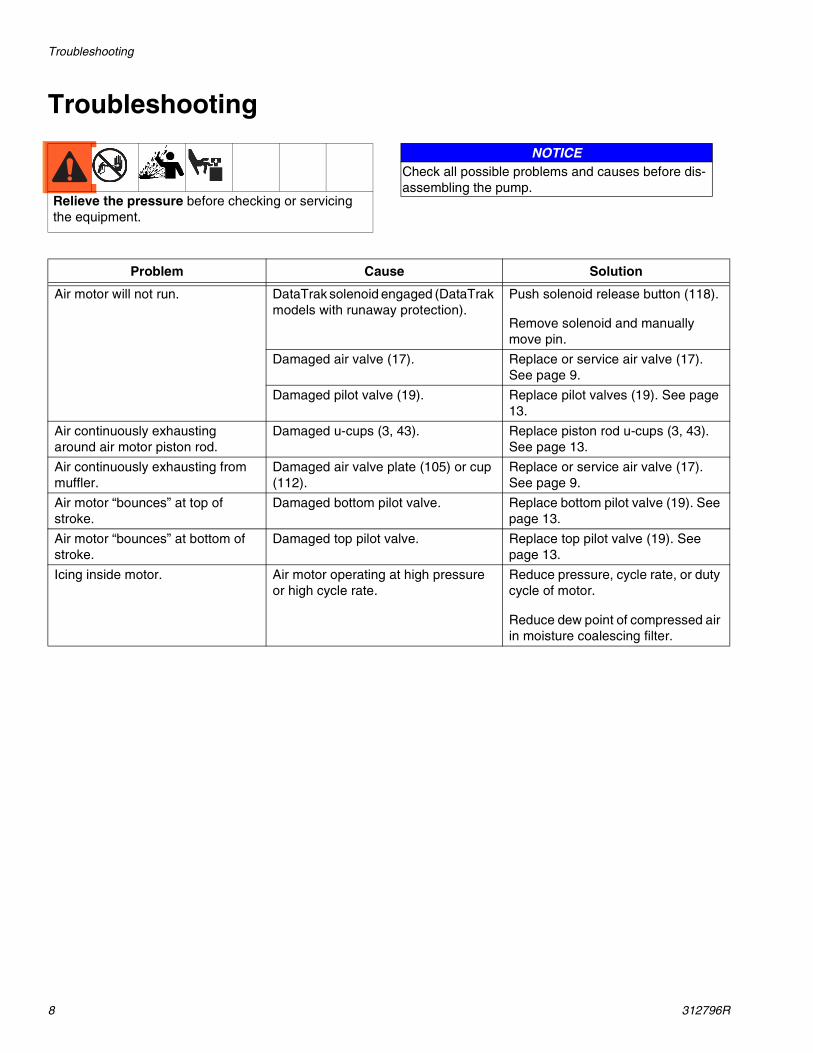
Troubleshooting
Relieve the pressure before checking or servicing the equipment.
NOTICECheck all possible problems and causes before dis-assembling the pump.
Problem Cause Solution
Air motor will not run. DataTrak solenoid engaged (DataTrak models with runaway protection).
Push solenoid release button (118).
Remove solenoid and manually move pin.
Damaged air valve (17). Replace or service air valve (17). See page 9.
Damaged pilot valve (19). Replace pilot valves (19). See page 13.
Air continuously exhausting around air motor piston rod.
Damaged u-cups (3, 43). Replace piston rod u-cups (3, 43). See page 13.
Air continuously exhausting from muffler.
Damaged air valve plate (105) or cup (112).
Replace or service air valve (17). See page 9.
Air motor “bounces” at top of stroke.
Damaged bottom pilot valve. Replace bottom pilot valve (19). See page 13.
Air motor “bounces” at bottom of stroke.
Damaged top pilot valve. Replace top pilot valve (19). See page 13.
Icing inside motor. Air motor operating at high pressure or high cycle rate.
Reduce pressure, cycle rate, or duty cycle of motor.
Reduce dew point of compressed air in moisture coalescing filter.
Repair
312796R 9
Repair
Preventive Maintenance ScheduleThe operating conditions of your system determine how often maintenance is required. Establish a preventive maintenance schedule by recording when and what kind of maintenance is needed, and then determine a regular schedule for checking your system.
Pressure Relief Procedure
1. Engage the trigger lock.
2. Close the bleed-type master valve.
3. Disengage the trigger lock.
4. Hold a metal part of the gun firmly to a grounded metal pail. Trigger the gun to relieve pressure.
5. Engage the trigger lock.
6. Open all fluid drain valves in the system, having a waste container ready to catch drainage. Leave drain valve(s) open until you are ready to spray again.
7. If you suspect the spray tip or hose is clogged or that pressure has not been fully relieved after follow-ing the steps above, VERY SLOWLY loosen tip guard retaining nut or hose end coupling to relieve pressure gradually, then loosen completely. Clear hose or tip obstruction.
Repair Air Valve
Replace Complete Air Valve
1. Stop the pump at the middle of its stroke. Relieve the pressure. See procedure at left.
2. Disconnect the air line to the motor.
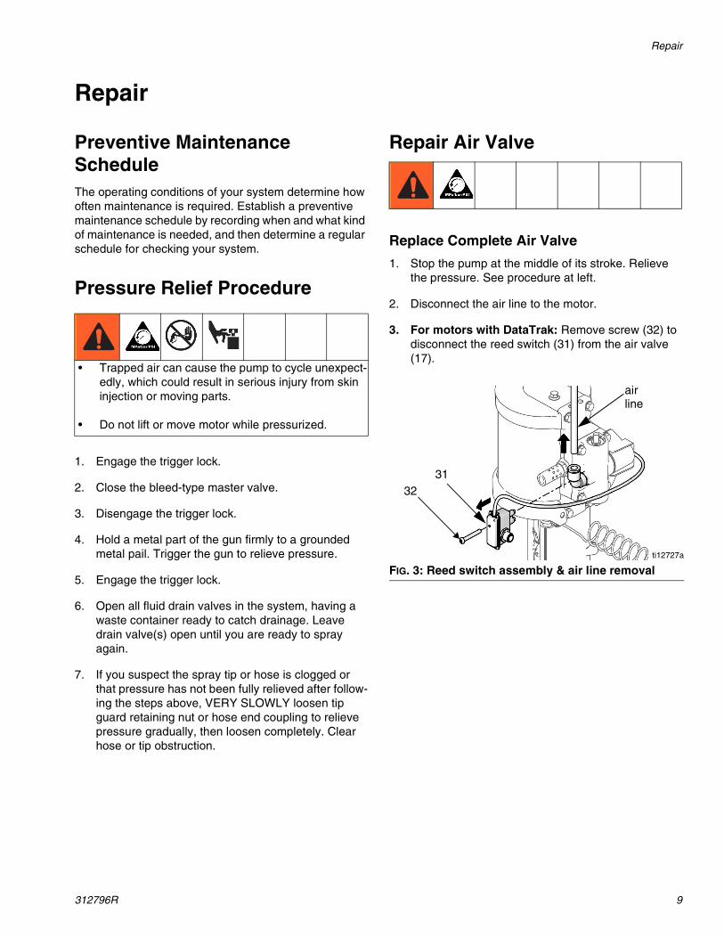
3. For motors with DataTrak: Remove screw (32) to disconnect the reed switch (31) from the air valve (17).
• Trapped air can cause the pump to cycle unexpect-edly, which could result in serious injury from skin injection or moving parts.
• Do not lift or move motor while pressurized.
FIG. 3: Reed switch assembly & air line removalti12727a
3132
airline
Repair
10 312796R
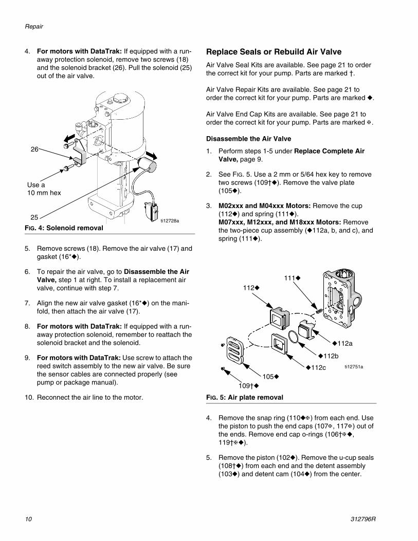
4. For motors with DataTrak: If equipped with a run-away protection solenoid, remove two screws (18) and the solenoid bracket (26). Pull the solenoid (25) out of the air valve.
5. Remove screws (18). Remove the air valve (17) and gasket (16*◆).
6. To repair the air valve, go to Disassemble the Air Valve, step 1 at right. To install a replacement air valve, continue with step 7.
7. Align the new air valve gasket (16*◆) on the mani-fold, then attach the air valve (17).
8. For motors with DataTrak: If equipped with a run-away protection solenoid, remember to reattach the solenoid bracket and the solenoid.
9. For motors with DataTrak: Use screw to attach the reed switch assembly to the new air valve. Be sure the sensor cables are connected properly (see pump or package manual).
10. Reconnect the air line to the motor.
Replace Seals or Rebuild Air Valve
Air Valve Seal Kits are available. See page 21 to order the correct kit for your pump. Parts are marked †.
Air Valve Repair Kits are available. See page 21 to order the correct kit for your pump. Parts are marked ◆.
Air Valve End Cap Kits are available. See page 21 to order the correct kit for your pump. Parts are marked ✠ .
Disassemble the Air Valve
1. Perform steps 1-5 under Replace Complete Air Valve, page 9.
2. See FIG. 5. Use a 2 mm or 5/64 hex key to remove two screws (109†◆). Remove the valve plate (105◆).
3. M02xxx and M04xxx Motors: Remove the cup (112◆) and spring (111◆).M07xxx, M12xxx, and M18xxx Motors: Remove the two-piece cup assembly (◆112a, b, and c), and spring (111◆).
4. Remove the snap ring (110◆✠ ) from each end. Use the piston to push the end caps (107✠ , 117✠ ) out of the ends. Remove end cap o-rings (106†✠◆, 119†✠◆).
5. Remove the piston (102◆). Remove the u-cup seals (108†◆) from each end and the detent assembly (103◆) and detent cam (104◆) from the center.
FIG. 4: Solenoid removalti12728a
Use a10 mm hex
26
25
FIG. 5: Air plate removal
109†◆
105◆
112◆
111◆
ti12751a◆112c
◆112b
◆112a

Repair
312796R 11
FIG. 6: Air valve assembly
118✠
117✠
106†✠◆
110◆✠
25
110◆✠
107✠
107✠
109†◆
105◆
112◆
111◆
103◆
102◆
ti11840a
26
101104◆
32
31
110◆✠
1
1
1
1
1
1
1
1 Apply lubricant.
106†✠◆
106†✠◆
108†◆
108†◆
DataTrak Models with Runaway Protection
119†✠◆
Two-Piece Cup for M07xxx, M12xxx, and M18xxx Motors
◆112c1
◆112b1
◆112a
Repair
12 312796R
Reassemble the Air Valve
1. Lubricate detent cam (104◆) and install into hous-ing.
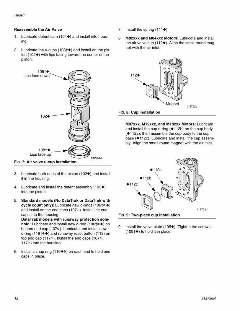
2. Lubricate the u-cups (108†◆) and install on the pis-ton (102◆) with lips facing toward the center of thepiston.
3. Lubricate both ends of the piston (102◆) and install it in the housing.
4. Lubricate and install the detent assembly (103◆) into the piston.
5. Standard models (No DataTrak or DataTrak with cycle count only): Lubricate new o-rings (106†✠◆) and install on the end caps (107✠ ). Install the end caps into the housing.DataTrak models with runaway protection sole-noid: Lubricate and install new o-ring (106†✠◆) on bottom end cap (107✠ ). Lubricate and install new o-ring (119†✠◆) and runaway reset button (118) on top end cap (117✠ ). Install the end caps (107✠ , 117✠ ) into the housing.
6. Install a snap ring (110◆✠ ) on each end to hold end caps in place.
7. Install the spring (111◆).
8. M02xxx and M04xxx Motors: Lubricate and install the air valve cup (112◆). Align the small round mag-net with the air inlet.
M07xxx, M12xxx, and M18xxx Motors: Lubricate and install the cup o-ring (◆112b) on the cup body (◆112a), then assemble the cup body to the cup base (◆112c). Lubricate and install the cup assem-bly. Align the small round magnet with the air inlet.
9. Install the valve plate (105◆). Tighten the screws (109†◆) to hold it in place.
FIG. 7: Air valve u-cup installation
Lips face down
Lips face up
108†◆
108†◆
102◆
ti12754a
FIG. 8: Cup installation
FIG. 9: Two-piece cup installation
Magnet
112◆
ti12752a
◆112c
◆112b
◆112a
ti12752b

Repair
312796R 13
Replace Pilot Valves1. Stop the pump at the middle of its stroke. Relieve
the pressure. See page 9.
2. Disconnect the air line to the motor.
3. Remove the tie rod shield (TS). Slide the drip shield (DS) down on the tie rods.
4. Use a 10 mm socket wrench to remove the old pilot valves (19) from the top and bottom covers.
5. Lubricate and install the new pilot valves (19). Torque to 95-105 in-lb (11-12 N•m).
Repair Air Motor
NOTE: Air Motor Seal Kits are available. See page 21 for the correct kit for your motor. Parts included in the kit are marked with an asterisk (*). For best results, use all the parts in the kit.
Disconnect the Air Motor
1. Flush the pump, if possible. (See package manual) Relieve the pressure. (See page 9.)
2. Disconnect the air and fluid hoses, the ground wire, and the tie rod shield.
3. Hold the flats of the air motor piston rod with a wrench. Use another wrench to loosen the coupling nut (CN).
4. Remove the tie rod nuts (TN).
5. Use a socket to remove the mounting screws (MS).
6. Lift up on the air motor to remove it. The tie rods and drip shield will remain attached.
TSDSti12916a
FIG. 10: Coupling nut removal
FIG. 11: Air motor removal
Cart Mount: Remove the two screws on the arms and tip back or remove the air control panel for eas-ier removal of the air motor.
CN
TNti12815a
MSti12818a
Repair
14 312796R
Disassemble the Air Motor
1. For motors with DataTrak: Remove screw to dis-connect the reed switch from the air valve. See FIG. 3, page 9.
2. Use a 10 mm socket wrench to remove four screws (18). Remove the air valve (17) and gasket (16*◆).
3. Remove the muffler(s).
4. Remove four screws (18) and remove the manifold (15*) and two gaskets (14*).
5. Use a 10 mm socket wrench to remove the pilot valves (19) from the top and bottom cover.
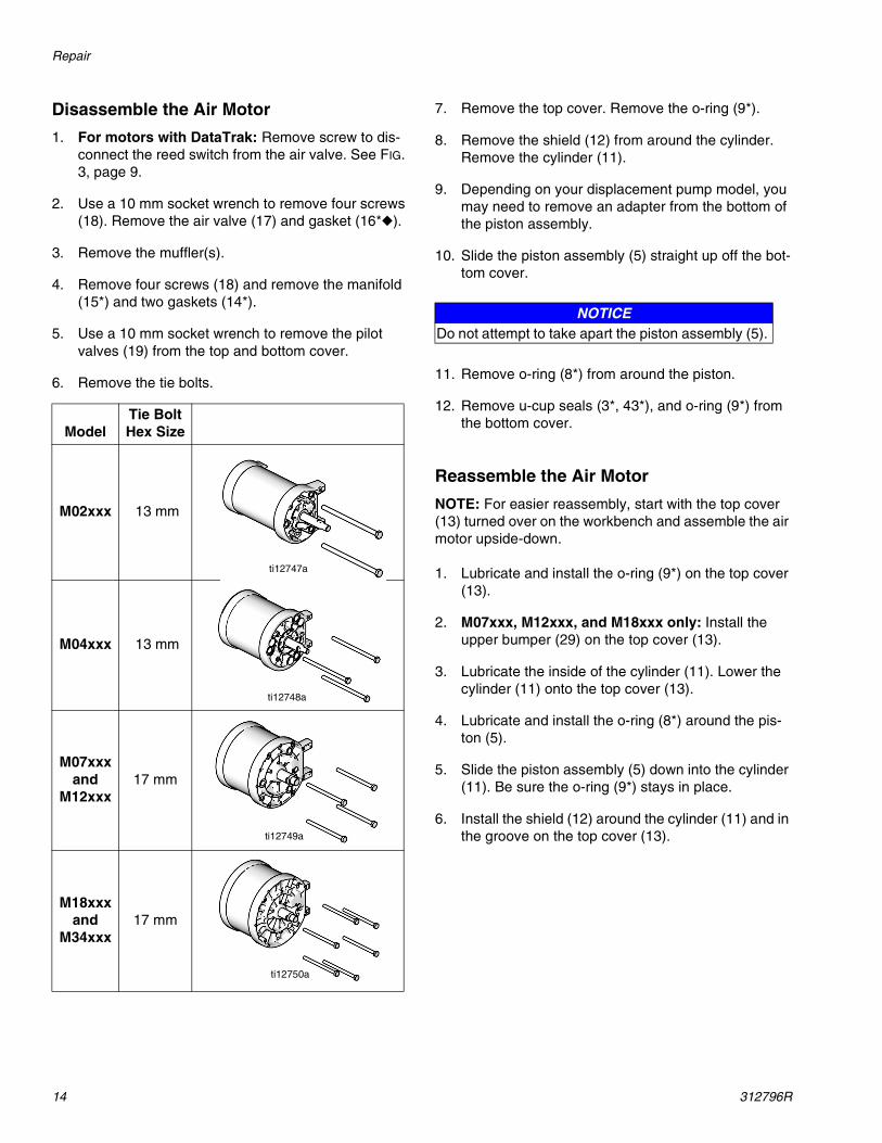
6. Remove the tie bolts.
7. Remove the top cover. Remove the o-ring (9*).
8. Remove the shield (12) from around the cylinder. Remove the cylinder (11).
9. Depending on your displacement pump model, you may need to remove an adapter from the bottom of the piston assembly.
10. Slide the piston assembly (5) straight up off the bot-tom cover.
11. Remove o-ring (8*) from around the piston.
12. Remove u-cup seals (3*, 43*), and o-ring (9*) from the bottom cover.
Reassemble the Air Motor
NOTE: For easier reassembly, start with the top cover (13) turned over on the workbench and assemble the air motor upside-down.
1. Lubricate and install the o-ring (9*) on the top cover (13).
2. M07xxx, M12xxx, and M18xxx only: Install the upper bumper (29) on the top cover (13).
3. Lubricate the inside of the cylinder (11). Lower the cylinder (11) onto the top cover (13).
4. Lubricate and install the o-ring (8*) around the pis-ton (5).
5. Slide the piston assembly (5) down into the cylinder (11). Be sure the o-ring (9*) stays in place.
6. Install the shield (12) around the cylinder (11) and in the groove on the top cover (13).
ModelTie Bolt Hex Size
M02xxx 13 mm
M04xxx 13 mm
M07xxxand
M12xxx17 mm
M18xxx and
M34xxx17 mm
ti12747a
ti12748a
ti12749a
ti12750a
NOTICEDo not attempt to take apart the piston assembly (5).
Repair
312796R 15
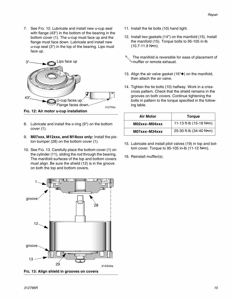
7. See FIG. 12. Lubricate and install new u-cup seal with flange (43*) in the bottom of the bearing in the bottom cover (1). The u-cup must face up and the flange must face down. Lubricate and install new u-cup seal (3*) in the top of the bearing. Lips must face up.
8. Lubricate and install the o-ring (9*) on the bottom cover (1).
9. M07xxx, M12xxx, and M18xxx only: Install the pis-ton bumper (28) on the bottom cover (1).
10. See FIG. 13. Carefully place the bottom cover (1) on the cylinder (11), sliding the rod through the bearing. The manifold surfaces of the top and bottom covers must align. Be sure the shield (12) is in the groove on both the top and bottom covers.
11. Install the tie bolts (10) hand tight.
12. Install two gaskets (14*) on the manifold (15). Install the manifold (15). Torque bolts to 95-105 in-lb (10.7-11.9 N•m).
13. Align the air valve gasket (16*◆) on the manifold, then attach the air valve.
14. Tighten the tie bolts (10) halfway. Work in a criss-cross pattern. Check that the shield remains in the grooves on both covers. Continue tightening the bolts in pattern to the torque specified in the follow-ing table.
15. Lubricate and install pilot valves (19) in top and bot-tom cover. Torque to 95-105 in-lb (11-12 N•m).
16. Reinstall muffler(s).
FIG. 12: Air motor u-cup installation
FIG. 13: Align shield in grooves on covers
3*
43*
ti12755a
U-cup faces up. Flange faces down.
Lips face up
groove
groove
28
29
1
12
13
ti14544a
The manifold is reversible for ease of placement of muffler or remote exhaust.
Air Motor Torque
M02xxx–M04xxx 11-13 ft-lb (15-18 N•m)
M07xxx–M34xxx 25-30 ft-lb (34-40 N•m)
Parts
16 312796R
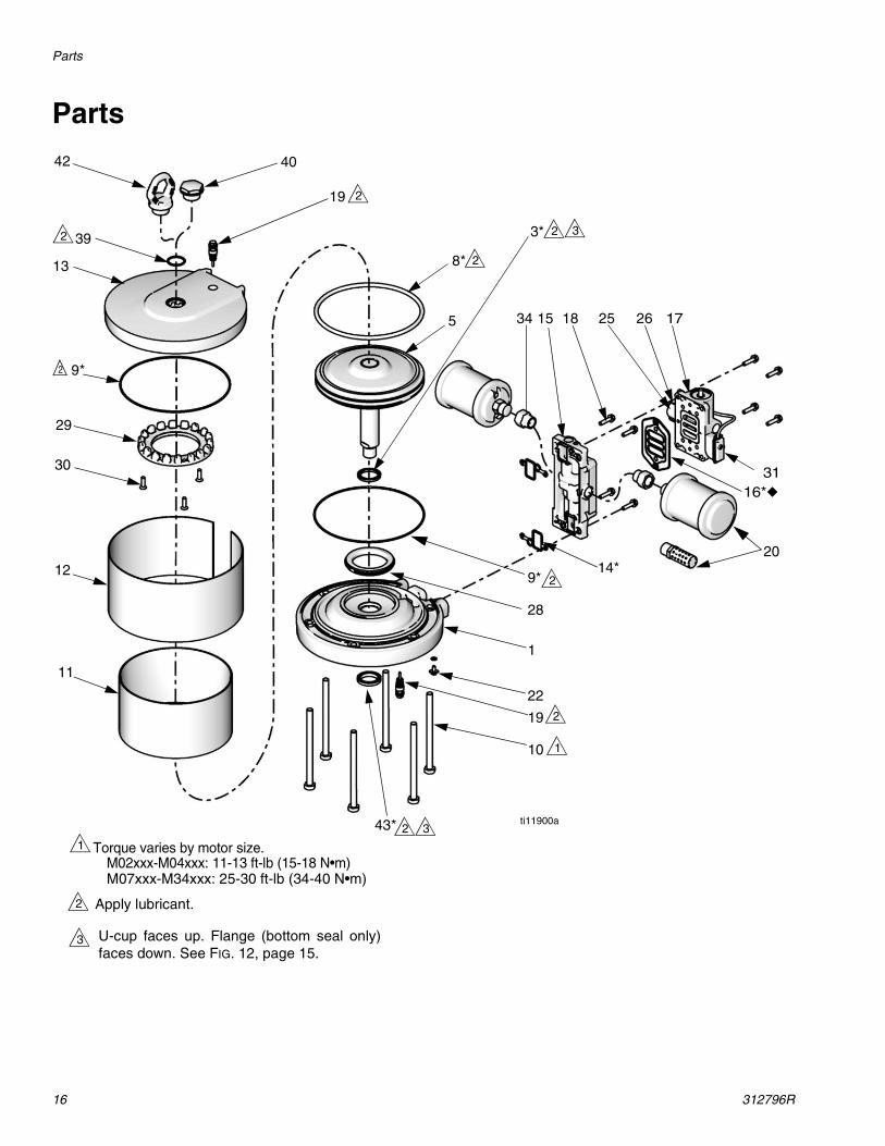
Parts
19
13
12
11
17
2014*
9*
9*
43*
3*
8*
5 15 18
19
10
22
31
2625
16*◆
2
2
2
2
2
2
2 Apply lubricant.
Torque varies by motor size.M02xxx-M04xxx: 11-13 ft-lb (15-18 N•m)M07xxx-M34xxx: 25-30 ft-lb (34-40 N•m)
1
29
ti11900a
28
34
1
2
30
1
392
4042
3 U-cup faces up. Flange (bottom seal only)faces down. See FIG. 12, page 15.
3
3

Air Motor Parts — All Models
312796R 17
Air Motor Parts — All ModelsRef. Description Qty M02xxx M04xxx M07xxx M12xxx M18xxx M34xxx
1 COVER, lower, assembly (includes 3, 9, 19, 22, 28, and 43)
1 24A541 24A545 24C398 24A549 24A553 24A553
3* U-CUP 2 Not sold separately. See Air Motor Seal Kit (page 21) orLower Cover Assembly (1, this table)
5 PISTON, motor, assembly 1 24A542 24A546 24C399 24A550 24A554 16G515
8* O-RING, piston 1 Not sold separately. See Air Motor Seal Kit (page 21) or Piston Assembly (5, this table)
9* O-RING, cover 2 Not sold separately. See Air Motor Seal Kit (page 21) orLower Cover Assembly (1, this table) or Upper Cover Assembly (13, this table)
10 BOLT, tie, hex head
M02xxx 2 15M314 ----- ----- ----- ----- -----
M04xxx 3 ----- 15M314 ----- ----- ----- -----
M07xxx 4 ----- ---- 15M316 ----- ----- -----
M12xxx 4 ----- ----- ----- 15M316 ----- -----
M18xxx 6 ----- ----- ----- ----- 15M316 -----
M34xxx 6 ----- ---- ----- ---- ----- 15M315
11 CYLINDER, motor 1 15M289 15M211 15M781 15M672 15M390 16A516
12 SHIELD, cylinder 1 15M302 15M212 15M782 15M676 15M539 16V472
13 COVER, upper, assembly, includes 9, 19, 39, 40, and 41
1 15M291 15X353 15X130 15X354 15X320 15X320
14* GASKET, manifold 2 Not sold separately. See Air Motor Seal Kit (page 21) orManifold Assembly (15, this table)
15 MANIFOLD, assembly, includes 14, 16, and 18 (qty. 4)
1 24A579 24A579 24A580 24A580 24A580 16G521
16*◆ GASKET, air valve 1 Not sold separately. See Air Motor Seal Kit (page 21) orManifold Assembly (15, this table)
17 VALVE, air, see page 21
Standard (for models with no Data-Trak or DataTrak with cycle count only)
1 24A351 24A351 24A352 24A352 24A352 24A352
Compatible with DataTrak with Run-away Protection
1 ----- 24A353 24A354 24A354 24A354 -----
Park - lowers to down position (cycle count only)
1 ----- ----- ----- 262608 ----- -----
18 SCREW, M6 x 25 varies Not sold separately. See Manifold Assembly (15, this table) or Solenoid Assembly (25, this table)
19 VALVE, pilot 2 24A366 24A366 24A366 24A366 24A366 24A366
20 MUFFLER
M02xxx 1 15M213 ----- ----- ----- ----- -----
M04xxx 1 ----- 15M213 ----- ----- ----- -----
M07xxx 1 ----- ----- 117237 ----- ----- -----
M12xxx 1 ----- ----- ----- 117237 ----- -----
M12Fxx 2 ----- ----- ----- 15M940 ----- -----
M18xxx 2 ----- ----- ----- ----- 117237 -----
M34xxx 1 ----- ----- ----- ----- ----- 102656
22 SCREW, ground 1 116343 116343 116343 116343 116343 116343
Air Motor Parts — All Models
18 312796R
* Included in Air Motor Seal Kit. See page 21.
▲ Replacement Warning labels, signs, tags, and cards are available at no cost.
25 SOLENOID/REED SWITCH, assembly, for DataTrak models with runaway protection, includes 18 (qty. 2 or 4 depending on model), 26, 31, 32, and 33.
1 See Reed Switch
(31, this table)
24B565 24B566 24B566 24B566
26 BRACKET, solenoid(for DataTrak models with runaway protection)
1 Not sold separately. See Solenoid/Reed Switch Assembly (25, this table)
28 BUMPER KIT, includes lower bum-per, upper bumper, and screws (M18xxx only)
1 24A914 24A914 24A915 24A915
29 BUMPER, upper (M18xxx only) 1 Not sold separately. See Bumper Kit (28,
this table)30 SCREW, M5, flat head (M18xxx
only)3
31 SWITCH, reed, includes 32(DataTrak models)
1 24B564 See Solenoid/Reed Switch Assembly(25, this table)
32 SCREW, reed switch, 8-32 x 1.50,(DataTrak models)
1 Not sold separately. See Solenoid/Reed Switch Assembly(25 this table) or Reed Switch (31, this table)
33 CLAMP, hose, not shown(DataTrak models)
1 Not sold separately. Order Kit 24A544 for
package of 10.
Not sold separately.Order Kit 24A548 for package of
10.
34 ADAPTER, muffler
M12xxx 1 15T560
M18xxx 2 15T560
35▲ LABEL, warning (not shown) 15W719 15W719 15W719 15W719 15W719 15F674
39 O-RING, upper cover plug 1 Not sold separately. See Upper Cover Assem-bly (13, this table), Plug (40), or Bushing (41)
110782
40 PLUG, upper cover (MxxLN0 or MxxLT0 models)
1 24E990 24E990 24E990 24E990 24E990
42 HOOK, lift. Not included. Order kit separately if needed, includes o-ring 39).
0 24E991 24E991 24E991 24E991 24E991
43 SEAL, u-cup with flange 1 Not sold separately. See Air Motor Seal Kit (page 21) orLower Cover Assembly (1, this table)
Ref. Description Qty M02xxx M04xxx M07xxx M12xxx M18xxx M34xxx
Air Valve Parts
312796R 19
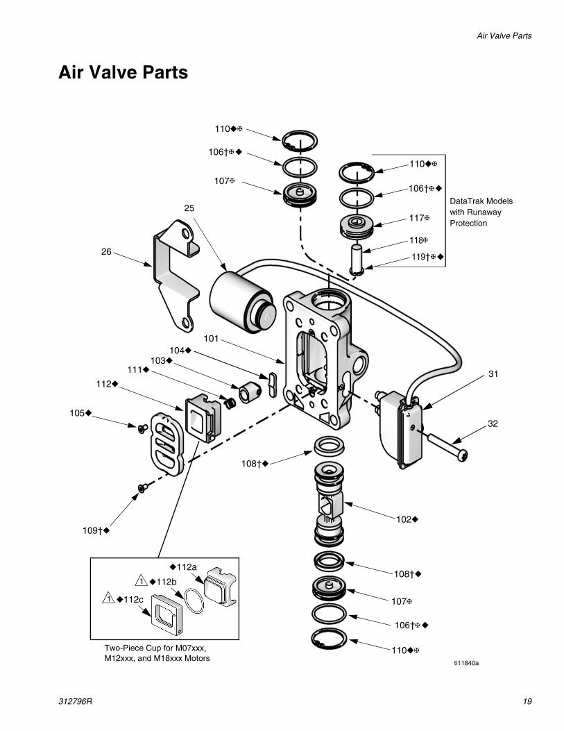
Air Valve Parts
117✠
106†✠◆
110◆✠
25
110◆✠
107✠
107✠
109†◆
105◆
112◆
111◆103◆
102◆
108†◆
108†◆
26
101104◆
32
31
110◆✠
ti11840a
106†✠◆
106†✠◆
118✠
DataTrak Models with Runaway Protection
119†✠◆
Two-Piece Cup for M07xxx, M12xxx, and M18xxx Motors
◆112c1
◆112b1
◆112a
Air Valve Parts
20 312796R
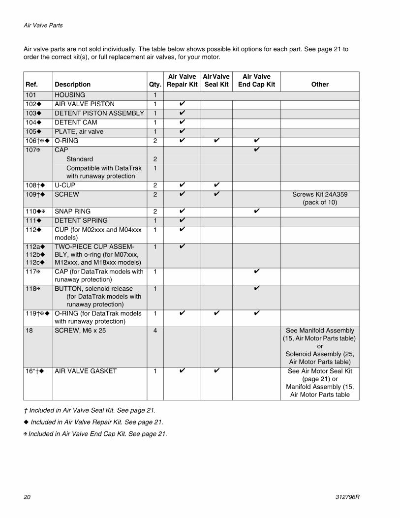
Air valve parts are not sold individually. The table below shows possible kit options for each part. See page 21 to order the correct kit(s), or full replacement air valves, for your motor.
† Included in Air Valve Seal Kit. See page 21.
◆ Included in Air Valve Repair Kit. See page 21.
✠ Included in Air Valve End Cap Kit. See page 21.
Ref. Description Qty.Air Valve Repair Kit
Air Valve Seal Kit
Air ValveEnd Cap Kit Other
101 HOUSING 1102◆ AIR VALVE PISTON 1 ✔
103◆ DETENT PISTON ASSEMBLY 1 ✔
104◆ DETENT CAM 1 ✔
105◆ PLATE, air valve 1 ✔
106†✠◆ O-RING 2 ✔ ✔ ✔
107✠ CAP ✔
Standard 2Compatible with DataTrak with runaway protection
1
108†◆ U-CUP 2 ✔ ✔
109†◆ SCREW 2 ✔ ✔ Screws Kit 24A359(pack of 10)
110◆✠ SNAP RING 2 ✔ ✔
111◆ DETENT SPRING 1 ✔
112◆ CUP (for M02xxx and M04xxx models)
1 ✔
112a◆
112b◆
112c◆
TWO-PIECE CUP ASSEM-BLY, with o-ring (for M07xxx, M12xxx, and M18xxx models)
1 ✔
117✠ CAP (for DataTrak models with runaway protection)
1 ✔
118✠ BUTTON, solenoid release(for DataTrak models with runaway protection)
1 ✔
119†✠◆ O-RING (for DataTrak models with runaway protection)
1 ✔ ✔ ✔
18 SCREW, M6 x 25 4 See Manifold Assembly (15, Air Motor Parts table)
orSolenoid Assembly (25, Air Motor Parts table)
16*†◆ AIR VALVE GASKET 1 ✔ ✔ See Air Motor Seal Kit (page 21) or
Manifold Assembly (15, Air Motor Parts table
Kits and Accessories
312796R 21
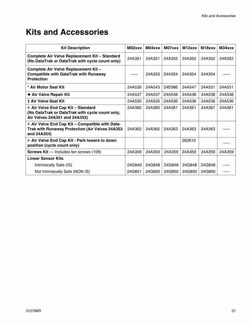
Kits and Accessories
Kit Description M02xxx M04xxx M07xxx M12xxx M18xxx M34xxx
Complete Air Valve Replacement Kit – Standard (No DataTrak or DataTrak with cycle count only)
24A351 24A351 24A352 24A352 24A352 24A352
Complete Air Valve Replacement Kit – Compatible with DataTrak with Runaway Protection
----- 24A353 24A354 24A354 24A354 -----
* Air Motor Seal Kit 24A539 24A543 24E986 24A547 24A551 24A551
◆ Air Valve Repair Kit 24A537 24A537 24A538 24A538 24A538 24A538
† Air Valve Seal Kit 24A535 24A535 24A536 24A536 24A536 24A536
✠ Air Valve End Cap Kit – Standard(No DataTrak or DataTrak with cycle count only, Air Valves 24A351 and 24A352)
24A360 24A360 24A361 24A361 24A361 24A361
✠ Air Valve End Cap Kit – Compatible with Data-Trak with Runaway Protection (Air Valves 24A353 and 24A354)
24A362 24A362 24A363 24A363 24A363 -----
✠ Air Valve End Cap Kit - Park lowers to down position (cycle count only)
262610-----
Screws Kit — Includes ten screws (109) 24A359 24A359 24A359 24A359 24A359 24A359
Linear Sensor Kits
Intrinsically Safe (IS) 24G849 24G848 24G848 24G848 24G848 -----
Not Intrinsically Safe (NON IS) 24G851 24G850 24G850 24G850 24G850 -----
Dimensions
22 312796R
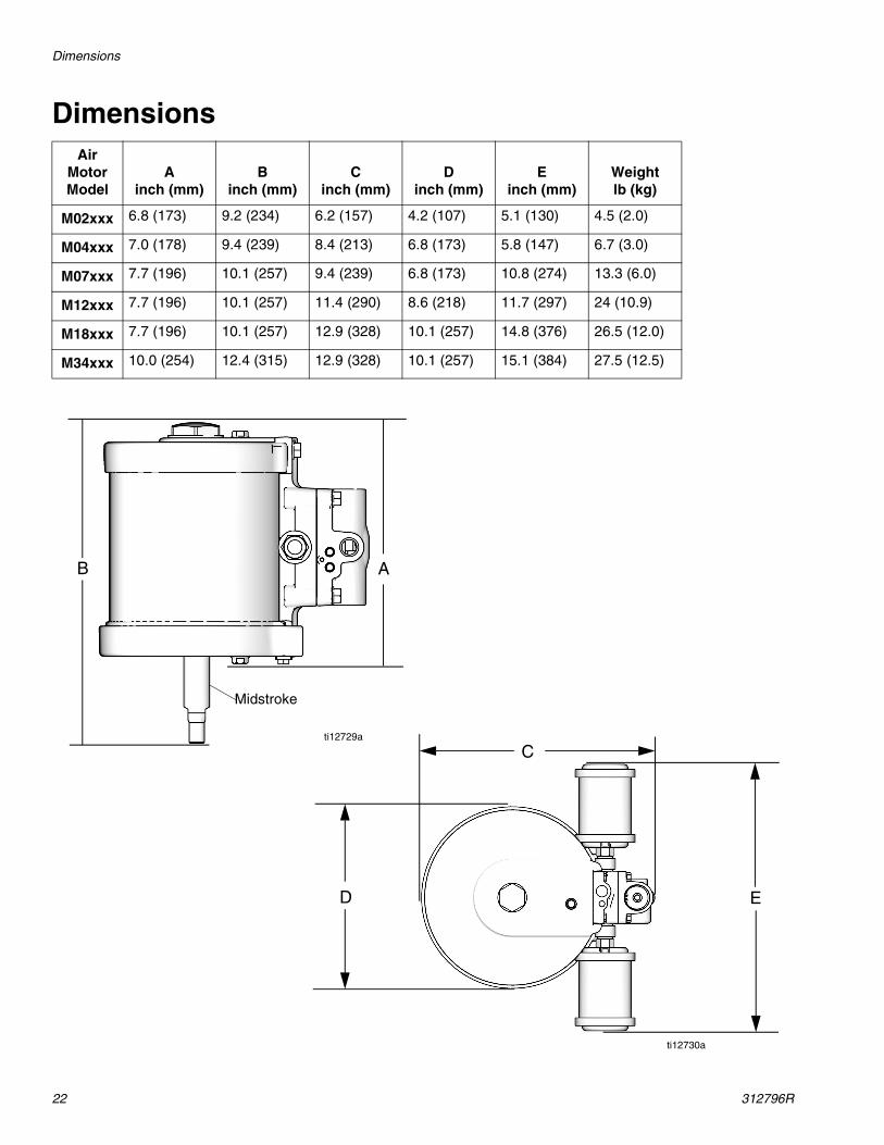
DimensionsAir
Motor Model
Ainch (mm)
Binch (mm)
Cinch (mm)
Dinch (mm)
Einch (mm)
Weightlb (kg)
M02xxx 6.8 (173) 9.2 (234) 6.2 (157) 4.2 (107) 5.1 (130) 4.5 (2.0)
M04xxx 7.0 (178) 9.4 (239) 8.4 (213) 6.8 (173) 5.8 (147) 6.7 (3.0)
M07xxx 7.7 (196) 10.1 (257) 9.4 (239) 6.8 (173) 10.8 (274) 13.3 (6.0)
M12xxx 7.7 (196) 10.1 (257) 11.4 (290) 8.6 (218) 11.7 (297) 24 (10.9)
M18xxx 7.7 (196) 10.1 (257) 12.9 (328) 10.1 (257) 14.8 (376) 26.5 (12.0)
M34xxx 10.0 (254) 12.4 (315) 12.9 (328) 10.1 (257) 15.1 (384) 27.5 (12.5)
B A
C
D E
ti12729a
ti12730a
Midstroke
Mounting Hole Diagrams
312796R 23
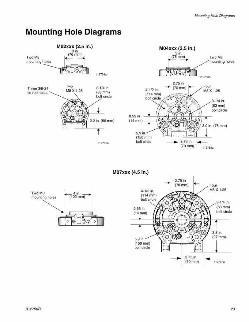
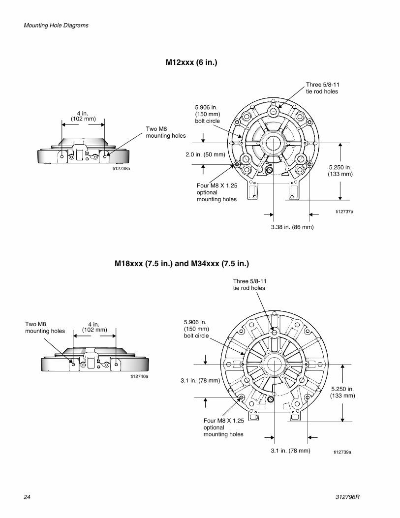
Mounting Hole Diagrams
3 in.(76 mm) 3 in.
(76 mm)
M02xxx (2.5 in.) M04xxx (3.5 in.)
Two M8mounting holes
Three 3/8-24tie rod holes
3-1/4 in.(83 mm)bolt circle
Two M8mounting holes
ti12734a
ti12733a
ti12736a
ti12735a
2.2 in. (56 mm)
4-1/2 in.(114 mm)bolt circle
3-1/4 in.(83 mm)bolt circle
3.0 in. (76 mm)
Four M8 X 1.25
5.9 in.(150 mm)bolt circle 2.75 in.
(70 mm)
2.75 in(70 mm)
0.55 in(14 mm)
Two M8 X 1.25
Two M8mounting holes
M07xxx (4.5 in.)
4 in.(102 mm)
ti12745a
3.8 in.(97 mm)
5.9 in.(150 mm)bolt circle
2.75 in.(70 mm)
2.75 in(70 mm)
4-1/2 in.(114 mm)bolt circle
3-1/4 in.(83 mm)bolt circle
0.55 in(14 mm)
Four M8 X 1.25
Mounting Hole Diagrams
24 312796R
4 in.(102 mm)
4 in.(102 mm)
M12xxx (6 in.)
Four M8 X 1.25optionalmounting holes
Four M8 X 1.25optionalmounting holes
Three 5/8-11tie rod holes
Two M8mounting holes
5.906 in.(150 mm)bolt circle
Two M8mounting holes
Three 5/8-11tie rod holes
5.906 in.(150 mm)bolt circle
ti12738a
ti12737a
ti12740a
ti12739a
3.38 in. (86 mm)
2.0 in. (50 mm)
5.250 in. (133 mm)
3.1 in. (78 mm)
5.250 in. (133 mm)
3.1 in. (78 mm)
M18xxx (7.5 in.) and M34xxx (7.5 in.)
Technical Data
312796R 25
Technical Data
* Sound power at 70 psi (0.48 MPa, 4.8 bar), 20 cpm. Sound power measured per ISO-9614-2.
** Sound pressure was tested 3.28 feet (1 m) from equipment.
Maximum air inlet pressure . . . . . . . . . . . . . . . . . . . . . . . 100 psi (0.7 MPa, 7.0 bar)Stroke length (all except M34xxx) . . . . . . . . . . . . . . . . . . 2.5 in.Stroke length (M34xxx only) . . . . . . . . . . . . . . . . . . . . . . 4.75 in.Air inlet size
M02xxx – M04xxx . . . . . . . . . . . . . . . . . . . . . . . .M07xxx – M34xxx . . . . . . . . . . . . . . . . . . . . . . . .
1/4 in.1/2 in.
Maximum motor speed. . . . . . . . . . . . . . . . . . . . . . . . . . .(Do not exceed maximum recommended speed of fluid pump, to prevent premature pump wear.)
60 cycles per minute
Sound dataM02xxx Air Motor
Sound power* . . . . . . . . . . . . . . . . . . . . . . . . . . .Sound pressure** . . . . . . . . . . . . . . . . . . . . . . . .
82.8 dBA72.9 dBA
M04xxx Air MotorSound power* . . . . . . . . . . . . . . . . . . . . . . . . . . .Sound pressure** . . . . . . . . . . . . . . . . . . . . . . . .
83.4 dBA73.5 dBA
M07xxx and M12xxx Air MotorSound power* . . . . . . . . . . . . . . . . . . . . . . . . . . .Sound pressure** . . . . . . . . . . . . . . . . . . . . . . . .
80.1 dBA70.2 dBA
M18xxx and M34xxx Air MotorSound power* . . . . . . . . . . . . . . . . . . . . . . . . . . .Sound pressure** . . . . . . . . . . . . . . . . . . . . . . . .
78.8 dBA68.9 dBA

All written and visual data contained in this document reflects the latest product information available at the time of publication. Graco reserves the right to make changes at any time without notice.
Original instructions. This manual contains English. MM 312796
Graco Headquarters: MinneapolisInternational Offices: Belgium, China, Japan, Korea
GRACO INC. AND SUBSIDIARIES • P.O. BOX 1441 • MINNEAPOLIS MN 55440-1441 • USA
Copyright 2011, Graco Inc. All Graco manufacturing locations are registered to ISO 9001.www.graco.com
Revised October 2014
Graco Standard WarrantyGraco warrants all equipment referenced in this document which is manufactured by Graco and bearing its name to be free from defects in material and workmanship on the date of sale to the original purchaser for use. With the exception of any special, extended, or limited warranty published by Graco, Graco will, for a period of twelve months from the date of sale, repair or replace any part of the equipment determined by Graco to be defective. This warranty applies only when the equipment is installed, operated and maintained in accordance with Graco’s written recommendations.
This warranty does not cover, and Graco shall not be liable for general wear and tear, or any malfunction, damage or wear caused by faulty installation, misapplication, abrasion, corrosion, inadequate or improper maintenance, negligence, accident, tampering, or substitution of non-Graco component parts. Nor shall Graco be liable for malfunction, damage or wear caused by the incompatibility of Graco equipment with structures, accessories, equipment or materials not supplied by Graco, or the improper design, manufacture, installation, operation or maintenance of structures, accessories, equipment or materials not supplied by Graco.
This warranty is conditioned upon the prepaid return of the equipment claimed to be defective to an authorized Graco distributor for verification of the claimed defect. If the claimed defect is verified, Graco will repair or replace free of charge any defective parts. The equipment will be returned to the original purchaser transportation prepaid. If inspection of the equipment does not disclose any defect in material or workmanship, repairs will be made at a reasonable charge, which charges may include the costs of parts, labor, and transportation.
THIS WARRANTY IS EXCLUSIVE, AND IS IN LIEU OF ANY OTHER WARRANTIES, EXPRESS OR IMPLIED, INCLUDING BUT NOT LIMITED TO WARRANTY OF MERCHANTABILITY OR WARRANTY OF FITNESS FOR A PARTICULAR PURPOSE.
Graco’s sole obligation and buyer’s sole remedy for any breach of warranty shall be as set forth above. The buyer agrees that no other remedy (including, but not limited to, incidental or consequential damages for lost profits, lost sales, injury to person or property, or any other incidental or consequential loss) shall be available. Any action for breach of warranty must be brought within two (2) years of the date of sale.
GRACO MAKES NO WARRANTY, AND DISCLAIMS ALL IMPLIED WARRANTIES OF MERCHANTABILITY AND FITNESS FOR A PARTICULAR PURPOSE, IN CONNECTION WITH ACCESSORIES, EQUIPMENT, MATERIALS OR COMPONENTS SOLD BUT NOT MANUFACTURED BY GRACO. These items sold, but not manufactured by Graco (such as electric motors, switches, hose, etc.), are subject to the warranty, if any, of their manufacturer. Graco will provide purchaser with reasonable assistance in making any claim for breach of these warranties.
In no event will Graco be liable for indirect, incidental, special or consequential damages resulting from Graco supplying equipment hereunder, or the furnishing, performance, or use of any products or other goods sold hereto, whether due to a breach of contract, breach of warranty, the negligence of Graco, or otherwise.
FOR GRACO CANADA CUSTOMERSThe Parties acknowledge that they have required that the present document, as well as all documents, notices and legal proceedings entered into, given or instituted pursuant hereto or relating directly or indirectly hereto, be drawn up in English. Les parties reconnaissent avoir convenu que la rédaction du présente document sera en Anglais, ainsi que tous documents, avis et procédures judiciaires exécutés, donnés ou intentés, à la suite de ou en rapport, directement ou indirectement, avec les procédures concernées.
Graco InformationFor the latest information about Graco products, visit www.graco.com.
For patent information, see www.graco.com/patents.
TO PLACE AN ORDER, contact your Graco distributor or call to identify the nearest distributor.Phone: 612-623-6921 or Toll Free: 1-800-328-0211 Fax: 612-378-3505