nylon-coated ultra high molecular weight polyethylene fabric for enhanced penetration resistance
TRANSCRIPT
Nylon-Coated Ultra High Molecular Weight Polyethylene Fabric forEnhanced Penetration Resistance
Dariush Firouzi,1 Daniel A. Foucher,2 Habiba Bougherara1
1Department of Mechanical and Industrial Engineering, Ryerson University, Toronto, Ontario, Canada M5B 2K32Department of Chemistry and Biology, Ryerson University, Toronto, Ontario, Canada M5B 2K3Correspondence to: H. Bougherara (E - mail: [email protected]).
ABSTRACT: A coating of Nylon 6,6 or 6,12 was used to improve the penetration resistance of ultra high molecular weight polyethylene
(UHMWPE) fabric that would be potentially useful in the manufacture of flexible body armor against spike/knife threats. Quasi-
static test results for the spike penetrator showed a 77% and 86% improvement in the puncture resistance of Nylon 6,6 and Nylon
6,12 coated UHMWPE (respectively) over a neat fabric target of equivalent areal densities. Dynamic impact testing demonstrated dra-
matic improvement in the puncture resistance of nylon-coated fabrics while only a slight improvement in stab resistance was observed
comparing samples with equivalent areal densities. Photography of ruptured areas after quasi-static testing revealed limited fiber
motion or fiber stretching with no evidence of fiber pullout for nylon-coated fabric samples in contrast to neat fabric. This suggests
that there was a significant increase in energy absorption by nylon-coated fabrics at impact. VC 2014 Wiley Periodicals, Inc. J. Appl. Polym.
Sci. 2014, 131, 40350.
KEYWORDS: coatings; polyimides; fibers; textiles; applications
Received 25 August 2013; accepted 22 December 2013DOI: 10.1002/app.40350
INTRODUCTION
Stab and puncture resistant materials have become increasingly
more important in light of the higher incidence of knife assaults
in urban and military conflicts. Generally, providing good punc-
ture and stab resistance with body armor is more difficult to
achieve than ballistic resistance.1–11 Development of lightweight,
high strength, and high modulus fibers has introduced a new
era of soft body armor materials that has obsoleted conven-
tional forms of protection.12–15 Typically, high strength fibers
(e.g., KevlarVR , SpectraVR , and DyneemaVR ) are used in the manu-
facture of fabric-based body armor to provide ballistic resist-
ance, as these fibers possess high strength, high energy
absorption, and lightweight properties.10,16,17 However, they do
not meet the standards against stab attacks.1,2,6,10 More recently,
ultra high molecular weight polyethylene (UHMWPE) has
received considerable attention by several protection industries.
The light weight, high strength, high elastic modulus, excellent
chemical resistance, and low moisture absorption properties of
UHMWPE make it an ideal alternative to other reinforced
fibers, such as Kevlar.11,13,18–20
Previous studies have investigated the improvement in ballistic/
puncture resistance of high strength fabrics impregnated with
shear thickening fluid (STF), also known as liquid body armor
technology although the cut resistance was not changed signifi-
cantly.1–4,8,9,14–17,21–27 A significant drawback with the use of
this technology is that STFs can lose their unique rheological
properties with aging or exposure to moisture.8 In addition,
UHMWPE, unlike Kevlar, is inherently inert with a low surface
energy and a smooth fiber surface 13,18,28–30 that often results in
poor interaction with other materials such as STFs. In the pres-
ent study, Nylon 6,6 and 6,12 coatings to increase the perform-
ance and penetration resistance of UHMWPE fabric were
investigated,31 using quasi-static and dynamic impact testing
and discussed below.
MATERIALS AND EXPERIMENTAL DETAILS
Materials
Nylon 6,6 (C12H26N2O2, q 5 1.14 g mL21) and 6,12
(C18H34O2N2, q 5 1.13 g mL21) pellets (Sigma Aldrich, Can-
ada) were used to coat UHMWPE fabric samples. Anhydrous
methyl (MeOH) and ethyl (EtOH) alcohol and ASC grade
anhydrous calcium chloride, CaCl2 (VWR, Canada) were used
to dissolve nylon pellets. The UHMWPE plain woven fabric
with an areal density of 231 g m22 and 21 3 21 yarns per inch
were supplied by Barrday, Canada.
Nylon Coating Preparation
Nylon 6,6 and 6,12 pellets were dissolved in anhydrous MeOH
and EtOH, respectively, in the presence of anhydrous CaCl2.
VC 2014 Wiley Periodicals, Inc.
WWW.MATERIALSVIEWS.COM J. APPL. POLYM. SCI. 2014, DOI: 10.1002/APP.4035040350 (1 of 9)
The ratio of nylon to CaCl2 to alcohol in solution was most
preferably 1 : 5 : 21 (by weight). The solution was heated to the
reflux temperature of the alcohol for several hours to com-
pletely dissolve the nylon pellets. Plain-woven UHMWPE fabric
was cut to the desired size and then submerged in the nylon/
alcohol solution for 30 s. A manual rubber-coated nip roller
was used to squeeze out excess nylon solution from the fabric
and ensure a reasonable uniform coated fabric sample. The
coated fabric samples were hung for several hours and then
rinsed in distilled water for 5 min to remove residual CaCl2.
The wet fabric samples were then hung overnight in the fume
hood to dry completely prior to testing.
Flexibility Test, Measurements, SEM, and DSC
Flexibility test and thickness measurement were done to exam-
ine the impact of the nylon-coated UHMWPE samples to neat
UHMWPE fabric. To perform the flexibility test, 16,21 coated
and neat UHMWPE fabric were cut to 5 cm 3 10 cm pieces
and sealed tightly in polyethylene bags using a manual impulse
sealer. The sample was then held firmly at the edge of a hard
piece of wood with 3.8 cm of the length of the sample exposed.
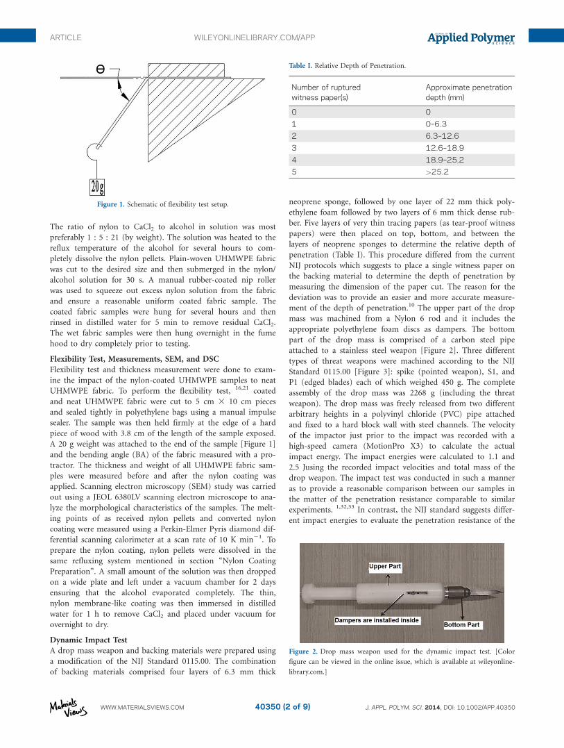
A 20 g weight was attached to the end of the sample [Figure 1]
and the bending angle (BA) of the fabric measured with a pro-
tractor. The thickness and weight of all UHMWPE fabric sam-
ples were measured before and after the nylon coating was
applied. Scanning electron microscopy (SEM) study was carried
out using a JEOL 6380LV scanning electron microscope to ana-
lyze the morphological characteristics of the samples. The melt-
ing points of as received nylon pellets and converted nylon
coating were measured using a Perkin-Elmer Pyris diamond dif-
ferential scanning calorimeter at a scan rate of 10 K min21. To
prepare the nylon coating, nylon pellets were dissolved in the
same refluxing system mentioned in section “Nylon Coating
Preparation”. A small amount of the solution was then dropped
on a wide plate and left under a vacuum chamber for 2 days
ensuring that the alcohol evaporated completely. The thin,
nylon membrane-like coating was then immersed in distilled
water for 1 h to remove CaCl2 and placed under vacuum for
overnight to dry.
Dynamic Impact Test
A drop mass weapon and backing materials were prepared using
a modification of the NIJ Standard 0115.00. The combination
of backing materials comprised four layers of 6.3 mm thick
neoprene sponge, followed by one layer of 22 mm thick poly-
ethylene foam followed by two layers of 6 mm thick dense rub-
ber. Five layers of very thin tracing papers (as tear-proof witness
papers) were then placed on top, bottom, and between the
layers of neoprene sponges to determine the relative depth of
penetration (Table I). This procedure differed from the current
NIJ protocols which suggests to place a single witness paper on
the backing material to determine the depth of penetration by
measuring the dimension of the paper cut. The reason for the
deviation was to provide an easier and more accurate measure-
ment of the depth of penetration.10 The upper part of the drop
mass was machined from a Nylon 6 rod and it includes the
appropriate polyethylene foam discs as dampers. The bottom
part of the drop mass is comprised of a carbon steel pipe
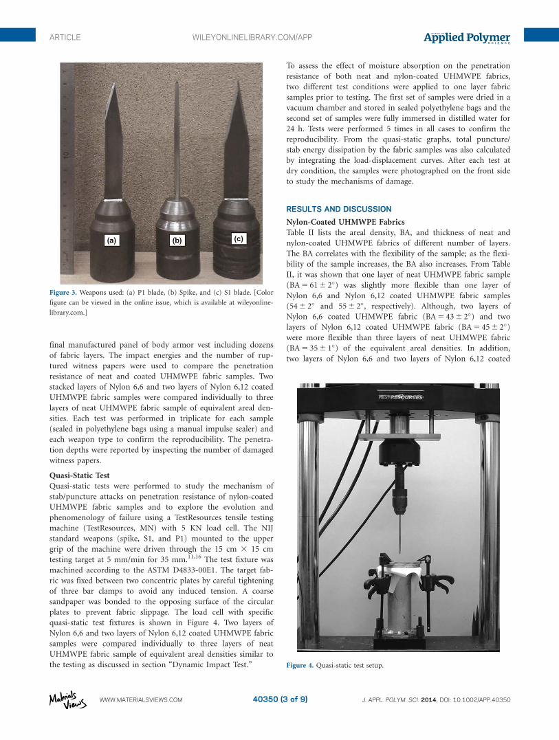
attached to a stainless steel weapon [Figure 2]. Three different
types of threat weapons were machined according to the NIJ
Standard 0115.00 [Figure 3]: spike (pointed weapon), S1, and
P1 (edged blades) each of which weighed 450 g. The complete
assembly of the drop mass was 2268 g (including the threat
weapon). The drop mass was freely released from two different
arbitrary heights in a polyvinyl chloride (PVC) pipe attached
and fixed to a hard block wall with steel channels. The velocity
of the impactor just prior to the impact was recorded with a
high-speed camera (MotionPro X3) to calculate the actual
impact energy. The impact energies were calculated to 1.1 and
2.5 Jusing the recorded impact velocities and total mass of the
drop weapon. The impact test was conducted in such a manner
as to provide a reasonable comparison between our samples in
the matter of the penetration resistance comparable to similar
experiments. 1,32,33 In contrast, the NIJ standard suggests differ-
ent impact energies to evaluate the penetration resistance of the
Figure 1. Schematic of flexibility test setup.
Table I. Relative Depth of Penetration.
Number of rupturedwitness paper(s)
Approximate penetrationdepth (mm)
0 0
1 0–6.3
2 6.3–12.6
3 12.6–18.9
4 18.9–25.2
5 >25.2
Figure 2. Drop mass weapon used for the dynamic impact test. [Color
figure can be viewed in the online issue, which is available at wileyonline-
library.com.]
ARTICLE WILEYONLINELIBRARY.COM/APP
WWW.MATERIALSVIEWS.COM J. APPL. POLYM. SCI. 2014, DOI: 10.1002/APP.4035040350 (2 of 9)
final manufactured panel of body armor vest including dozens
of fabric layers. The impact energies and the number of rup-
tured witness papers were used to compare the penetration
resistance of neat and coated UHMWPE fabric samples. Two
stacked layers of Nylon 6,6 and two layers of Nylon 6,12 coated
UHMWPE fabric samples were compared individually to three
layers of neat UHMWPE fabric sample of equivalent areal den-
sities. Each test was performed in triplicate for each sample
(sealed in polyethylene bags using a manual impulse sealer) and
each weapon type to confirm the reproducibility. The penetra-
tion depths were reported by inspecting the number of damaged
witness papers.
Quasi-Static Test
Quasi-static tests were performed to study the mechanism of
stab/puncture attacks on penetration resistance of nylon-coated
UHMWPE fabric samples and to explore the evolution and
phenomenology of failure using a TestResources tensile testing
machine (TestResources, MN) with 5 KN load cell. The NIJ
standard weapons (spike, S1, and P1) mounted to the upper
grip of the machine were driven through the 15 cm 3 15 cm
testing target at 5 mm/min for 35 mm.11,16 The test fixture was
machined according to the ASTM D4833-00E1. The target fab-
ric was fixed between two concentric plates by careful tightening
of three bar clamps to avoid any induced tension. A coarse
sandpaper was bonded to the opposing surface of the circular
plates to prevent fabric slippage. The load cell with specific
quasi-static test fixtures is shown in Figure 4. Two layers of
Nylon 6,6 and two layers of Nylon 6,12 coated UHMWPE fabric
samples were compared individually to three layers of neat
UHMWPE fabric sample of equivalent areal densities similar to
the testing as discussed in section “Dynamic Impact Test.”
To assess the effect of moisture absorption on the penetration
resistance of both neat and nylon-coated UHMWPE fabrics,
two different test conditions were applied to one layer fabric
samples prior to testing. The first set of samples were dried in a
vacuum chamber and stored in sealed polyethylene bags and the
second set of samples were fully immersed in distilled water for
24 h. Tests were performed 5 times in all cases to confirm the
reproducibility. From the quasi-static graphs, total puncture/
stab energy dissipation by the fabric samples was also calculated
by integrating the load-displacement curves. After each test at
dry condition, the samples were photographed on the front side
to study the mechanisms of damage.
RESULTS AND DISCUSSION
Nylon-Coated UHMWPE Fabrics
Table II lists the areal density, BA, and thickness of neat and
nylon-coated UHMWPE fabrics of different number of layers.
The BA correlates with the flexibility of the sample; as the flexi-
bility of the sample increases, the BA also increases. From Table
II, it was shown that one layer of neat UHMWPE fabric sample
(BA 5 61 6 2�) was slightly more flexible than one layer of
Nylon 6,6 and Nylon 6,12 coated UHMWPE fabric samples
(54 6 2� and 55 6 2�, respectively). Although, two layers of
Nylon 6,6 coated UHMWPE fabric (BA 5 43 6 2�) and two
layers of Nylon 6,12 coated UHMWPE fabric (BA 5 45 6 2�)were more flexible than three layers of neat UHMWPE fabric
(BA 5 35 6 1�) of the equivalent areal densities. In addition,
two layers of Nylon 6,6 and two layers of Nylon 6,12 coated
Figure 3. Weapons used: (a) P1 blade, (b) Spike, and (c) S1 blade. [Color
figure can be viewed in the online issue, which is available at wileyonline-
library.com.]
Figure 4. Quasi-static test setup.
ARTICLE WILEYONLINELIBRARY.COM/APP
WWW.MATERIALSVIEWS.COM J. APPL. POLYM. SCI. 2014, DOI: 10.1002/APP.4035040350 (3 of 9)
fabric samples were 34% and 31% thinner (respectively) com-
pared to three layers of neat UHMWPE fabric sample of equiva-
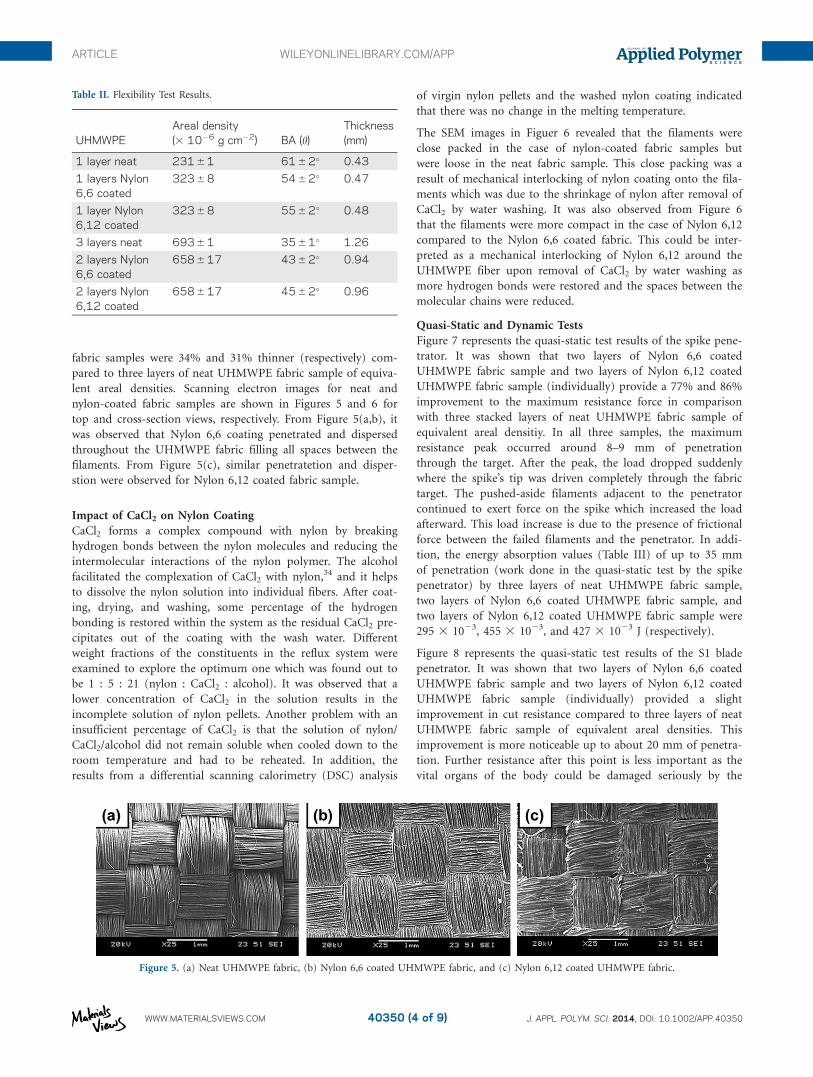
lent areal densities. Scanning electron images for neat and
nylon-coated fabric samples are shown in Figures 5 and 6 for
top and cross-section views, respectively. From Figure 5(a,b), it
was observed that Nylon 6,6 coating penetrated and dispersed
throughout the UHMWPE fabric filling all spaces between the
filaments. From Figure 5(c), similar penetratetion and disper-
stion were observed for Nylon 6,12 coated fabric sample.
Impact of CaCl2 on Nylon Coating
CaCl2 forms a complex compound with nylon by breaking
hydrogen bonds between the nylon molecules and reducing the
intermolecular interactions of the nylon polymer. The alcohol
facilitated the complexation of CaCl2 with nylon,34 and it helps
to dissolve the nylon solution into individual fibers. After coat-
ing, drying, and washing, some percentage of the hydrogen
bonding is restored within the system as the residual CaCl2 pre-
cipitates out of the coating with the wash water. Different
weight fractions of the constituents in the reflux system were
examined to explore the optimum one which was found out to
be 1 : 5 : 21 (nylon : CaCl2 : alcohol). It was observed that a
lower concentration of CaCl2 in the solution results in the
incomplete solution of nylon pellets. Another problem with an
insufficient percentage of CaCl2 is that the solution of nylon/
CaCl2/alcohol did not remain soluble when cooled down to the
room temperature and had to be reheated. In addition, the
results from a differential scanning calorimetry (DSC) analysis
of virgin nylon pellets and the washed nylon coating indicated
that there was no change in the melting temperature.
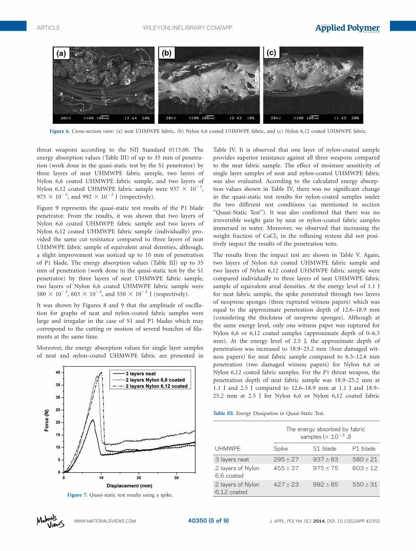
The SEM images in Figuer 6 revealed that the filaments were
close packed in the case of nylon-coated fabric samples but
were loose in the neat fabric sample. This close packing was a
result of mechanical interlocking of nylon coating onto the fila-
ments which was due to the shrinkage of nylon after removal of
CaCl2 by water washing. It was also observed from Figure 6
that the filaments were more compact in the case of Nylon 6,12
compared to the Nylon 6,6 coated fabric. This could be inter-
preted as a mechanical interlocking of Nylon 6,12 around the
UHMWPE fiber upon removal of CaCl2 by water washing as
more hydrogen bonds were restored and the spaces between the
molecular chains were reduced.
Quasi-Static and Dynamic Tests
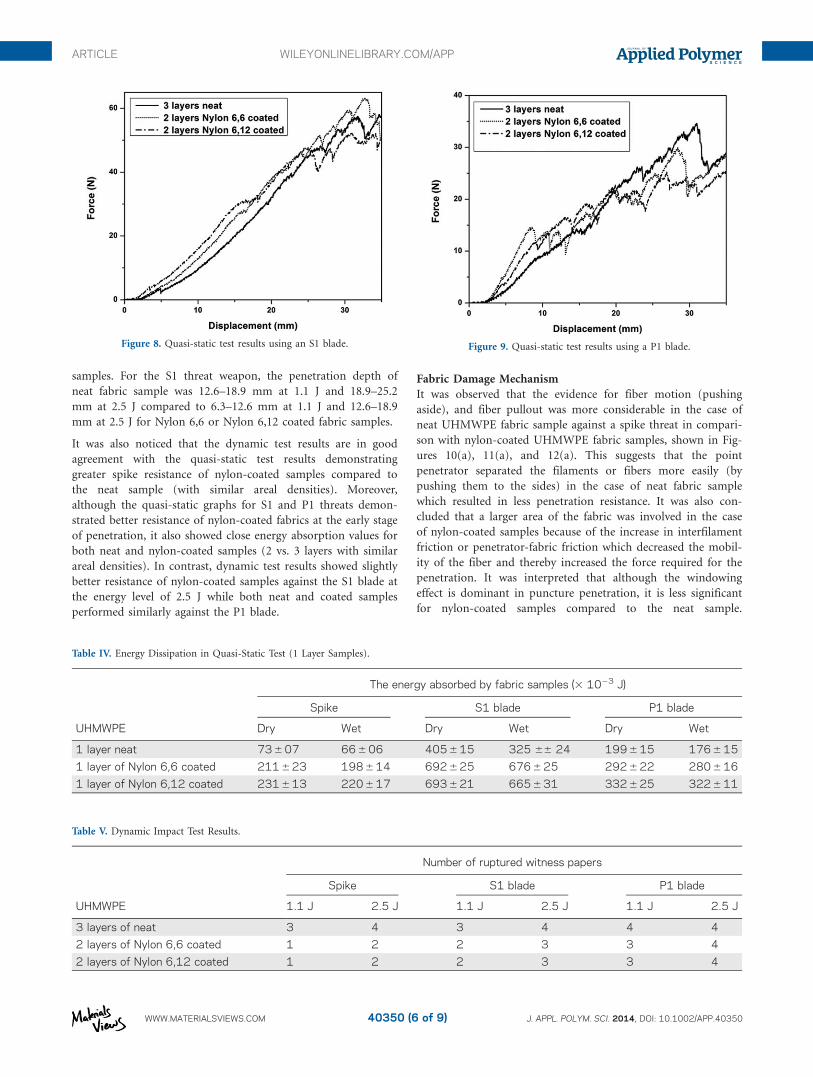
Figure 7 represents the quasi-static test results of the spike pene-
trator. It was shown that two layers of Nylon 6,6 coated
UHMWPE fabric sample and two layers of Nylon 6,12 coated
UHMWPE fabric sample (individually) provide a 77% and 86%
improvement to the maximum resistance force in comparison
with three stacked layers of neat UHMWPE fabric sample of
equivalent areal densitiy. In all three samples, the maximum
resistance peak occurred around 8–9 mm of penetration
through the target. After the peak, the load dropped suddenly
where the spike’s tip was driven completely through the fabric
target. The pushed-aside filaments adjacent to the penetrator
continued to exert force on the spike which increased the load
afterward. This load increase is due to the presence of frictional
force between the failed filaments and the penetrator. In addi-
tion, the energy absorption values (Table III) of up to 35 mm
of penetration (work done in the quasi-static test by the spike
penetrator) by three layers of neat UHMWPE fabric sample,
two layers of Nylon 6,6 coated UHMWPE fabric sample, and
two layers of Nylon 6,12 coated UHMWPE fabric sample were
295 3 1023, 455 3 1023, and 427 3 1023 J (respectively).
Figure 8 represents the quasi-static test results of the S1 blade
penetrator. It was shown that two layers of Nylon 6,6 coated
UHMWPE fabric sample and two layers of Nylon 6,12 coated
UHMWPE fabric sample (individually) provided a slight
improvement in cut resistance compared to three layers of neat
UHMWPE fabric sample of equivalent areal densities. This
improvement is more noticeable up to about 20 mm of penetra-
tion. Further resistance after this point is less important as the
vital organs of the body could be damaged seriously by the
Figure 5. (a) Neat UHMWPE fabric, (b) Nylon 6,6 coated UHMWPE fabric, and (c) Nylon 6,12 coated UHMWPE fabric.
Table II. Flexibility Test Results.
UHMWPEAreal density(3 1026 g cm22) BA (h)
Thickness(mm)
1 layer neat 231 6 1 61 6 2� 0.43
1 layers Nylon6,6 coated
323 6 8 54 6 2� 0.47
1 layer Nylon6,12 coated
323 6 8 55 6 2� 0.48
3 layers neat 693 6 1 35 6 1� 1.26
2 layers Nylon6,6 coated
658 6 17 43 6 2� 0.94
2 layers Nylon6,12 coated
658 6 17 45 6 2� 0.96
ARTICLE WILEYONLINELIBRARY.COM/APP
WWW.MATERIALSVIEWS.COM J. APPL. POLYM. SCI. 2014, DOI: 10.1002/APP.4035040350 (4 of 9)
threat weapons according to the NIJ Standard 0115.00. The
energy absorption values (Table III) of up to 35 mm of penetra-
tion (work done in the quasi-static test by the S1 penetrator) by
three layers of neat UHMWPE fabric sample, two layers of
Nylon 6,6 coated UHMWPE fabric sample, and two layers of
Nylon 6,12 coated UHMWPE fabric sample were 937 3 1023,
975 3 1023, and 992 3 1023 J (respectively).
Figure 9 represents the quasi-static test results of the P1 blade
penetrator. From the results, it was shown that two layers of
Nylon 6,6 coated UHMWPE fabric sample and two layers of
Nylon 6,12 coated UHMWPE fabric sample (individually) pro-
vided the same cut resistance compared to three layers of neat
UHMWPE fabric sample of equivalent areal densities, although,
a slight improvement was noticed up to 10 mm of penetration
of P1 blade. The energy absorption values (Table III) up to 35
mm of penetration (work done in the quasi-static test by the S1
penetrator) by three layers of neat UHMWPE fabric sample,
two layers of Nylon 6,6 coated UHMWPE fabric sample were
580 3 1023, 603 3 1023, and 550 3 1023 J (respectively).
It was shown by Figures 8 and 9 that the amplitude of oscilla-
tion for graphs of neat and nylon-coated fabric samples were
large and irregular in the case of S1 and P1 blades which may
correspond to the cutting or motion of several bunches of fila-
ments at the same time.
Moreover, the energy absorption values for single layer samples
of neat and nylon-coated UHMWPE fabric are presented in
Table IV. It is observed that one layer of nylon-coated sample
provides superior resistance against all three weapons compared
to the neat fabric sample. The effect of moisture sensitivity of
single layer samples of neat and nylon-coated UHMWPE fabric
was also evaluated. According to the calculated energy absorp-
tion values shown in Table IV, there was no significant change
in the quasi-static test results for nylon-coated samples under
the two different test conditions (as mentioned in section
“Quasi-Static Test”). It was also confirmed that there was no
irreversible weight gain by neat or nylon-coated fabric samples
immersed in water. Moreover, we observed that increasing the
weight fraction of CaCl2 in the refluxing system did not posi-
tively impact the results of the penetration tests.
The results from the impact test are shown in Table V. Again,
two layers of Nylon 6,6 coated UHMWPE fabric sample and
two layers of Nylon 6,12 coated UHMWPE fabric sample were
compared individually to three layers of neat UHMWPE fabric
sample of equivalent areal densities. At the energy level of 1.1 J
for neat fabric sample, the spike penetrated through two layers
of neoprene sponges (three ruptured witness papers) which was
equal to the approximate penetration depth of 12.6–18.9 mm
(considering the thickness of neoprene sponges). Although at
the same energy level, only one witness paper was ruptured for
Nylon 6,6 or 6,12 coated samples (approximate depth of 0–6.3
mm). At the energy level of 2.5 J, the approximate depth of
penetration was increased to 18.9–25.2 mm (four damaged wit-
ness papers) for neat fabric sample compared to 6.3–12.6 mm
penetration (two damaged witness papers) for Nylon 6,6 or
Nylon 6,12 coated fabric samples. For the P1 threat weapon, the
penetration depth of neat fabric sample was 18.9–25.2 mm at
1.1 J and 2.5 J compared to 12.6–18.9 mm at 1.1 J and 18.9–
25.2 mm at 2.5 J for Nylon 6,6 or Nylon 6,12 coated fabric
Figure 6. Cross-section view: (a) neat UHMWPE fabric, (b) Nylon 6,6 coated UHMWPE fabric, and (c) Nylon 6,12 coated UHMWPE fabric.
Figure 7. Quasi-static test results using a spike.
Table III. Energy Dissipation in Quasi-Static Test.
UHMWPE
The energy absorbed by fabricsamples (3 1023 J)
Spike S1 blade P1 blade
3 layers neat 295 6 27 937 6 83 580 6 21
2 layers of Nylon6,6 coated
455 6 37 975 6 75 603 6 12
2 layers of Nylon6,12 coated
427 6 23 992 6 85 550 6 31
ARTICLE WILEYONLINELIBRARY.COM/APP
WWW.MATERIALSVIEWS.COM J. APPL. POLYM. SCI. 2014, DOI: 10.1002/APP.4035040350 (5 of 9)
samples. For the S1 threat weapon, the penetration depth of
neat fabric sample was 12.6–18.9 mm at 1.1 J and 18.9–25.2
mm at 2.5 J compared to 6.3–12.6 mm at 1.1 J and 12.6–18.9
mm at 2.5 J for Nylon 6,6 or Nylon 6,12 coated fabric samples.
It was also noticed that the dynamic test results are in good
agreement with the quasi-static test results demonstrating
greater spike resistance of nylon-coated samples compared to
the neat sample (with similar areal densities). Moreover,
although the quasi-static graphs for S1 and P1 threats demon-
strated better resistance of nylon-coated fabrics at the early stage
of penetration, it also showed close energy absorption values for
both neat and nylon-coated samples (2 vs. 3 layers with similar
areal densities). In contrast, dynamic test results showed slightly
better resistance of nylon-coated samples against the S1 blade at
the energy level of 2.5 J while both neat and coated samples
performed similarly against the P1 blade.
Fabric Damage Mechanism
It was observed that the evidence for fiber motion (pushing
aside), and fiber pullout was more considerable in the case of
neat UHMWPE fabric sample against a spike threat in compari-
son with nylon-coated UHMWPE fabric samples, shown in Fig-
ures 10(a), 11(a), and 12(a). This suggests that the point
penetrator separated the filaments or fibers more easily (by
pushing them to the sides) in the case of neat fabric sample
which resulted in less penetration resistance. It was also con-
cluded that a larger area of the fabric was involved in the case
of nylon-coated samples because of the increase in interfilament
friction or penetrator-fabric friction which decreased the mobil-
ity of the fiber and thereby increased the force required for the
penetration. It was interpreted that although the windowing
effect is dominant in puncture penetration, it is less significant
for nylon-coated samples compared to the neat sample.
Figure 8. Quasi-static test results using an S1 blade. Figure 9. Quasi-static test results using a P1 blade.
Table IV. Energy Dissipation in Quasi-Static Test (1 Layer Samples).
UHMWPE
The energy absorbed by fabric samples (3 1023 J)
Spike S1 blade P1 blade
Dry Wet Dry Wet Dry Wet
1 layer neat 73 6 07 66 6 06 405 6 15 325 66 24 199 6 15 176 6 15
1 layer of Nylon 6,6 coated 211 6 23 198 6 14 692 6 25 676 6 25 292 6 22 280 6 16
1 layer of Nylon 6,12 coated 231 6 13 220 6 17 693 6 21 665 6 31 332 6 25 322 6 11
Table V. Dynamic Impact Test Results.
UHMWPE
Number of ruptured witness papers
Spike S1 blade P1 blade
1.1 J 2.5 J 1.1 J 2.5 J 1.1 J 2.5 J
3 layers of neat 3 4 3 4 4 4
2 layers of Nylon 6,6 coated 1 2 2 3 3 4
2 layers of Nylon 6,12 coated 1 2 2 3 3 4
ARTICLE WILEYONLINELIBRARY.COM/APP
WWW.MATERIALSVIEWS.COM J. APPL. POLYM. SCI. 2014, DOI: 10.1002/APP.4035040350 (6 of 9)
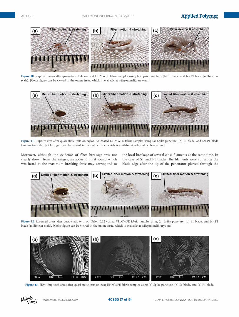
Moreover, although the evidence of fiber breakage was not
clearly shown from the images, an acoustic burst sound which
was heard at the maximum breaking force may correspond to
the local breakage of several close filaments at the same time. In
the case of S1 and P1 blades, the filaments were cut along the
blade edge after the tip of the penetrator pierced through the
Figure 10. Ruptured areas after quasi-static tests on neat UHMWPE fabric samples using (a) Spike puncture, (b) S1 blade, and (c) P1 blade (millimeter-
scale). [Color figure can be viewed in the online issue, which is available at wileyonlinelibrary.com.]
Figure 11. Rupture area after quasi-static tests on Nylon 6,6 coated UHMWPE fabric samples using (a) Spike puncture, (b) S1 blade, and (c) P1 blade
(millimeter-scale). [Color figure can be viewed in the online issue, which is available at wileyonlinelibrary.com.]
Figure 12. Ruptured areas after quasi-static tests on Nylon 6,12 coated UHMWPE fabric samples using (a) Spike puncture, (b) S1 blade, and (c) P1
blade (millimeter-scale). [Color figure can be viewed in the online issue, which is available at wileyonlinelibrary.com.]
Figure 13. SEM: Ruptured areas after quasi-static tests on neat UHMWPE fabric samples using (a) Spike puncture, (b) S1 blade, and (c) P1 blade.
ARTICLE WILEYONLINELIBRARY.COM/APP
WWW.MATERIALSVIEWS.COM J. APPL. POLYM. SCI. 2014, DOI: 10.1002/APP.4035040350 (7 of 9)
fabric, and the restriction in the mobility of filaments of coated
fabric samples became less important for cut resistance (as the
cutting mechanism dominated windowing effects). More fila-
ment breakages (or cuts) were observed for the nylon-coated
UHMWPE fabric samples as they were shown in Figures 10(b,c),
11(b,c), and 12(b,c). In addition, it could be interpreted that
blade threats result in more localized cut damage which is oppo-
site to what was observed for puncture threats. These could be
the key reason why nylon-coated samples show more improve-
ment over uncoated samples against spike threat but not against
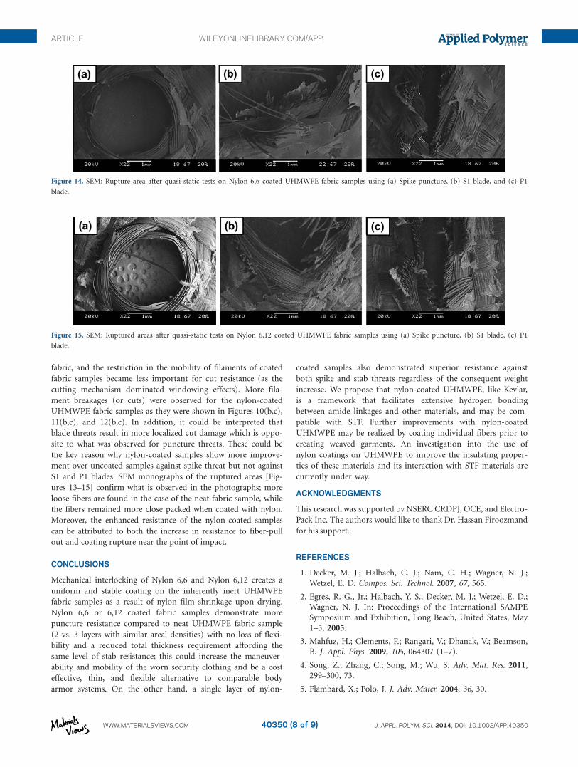
S1 and P1 blades. SEM monographs of the ruptured areas [Fig-
ures 13–15] confirm what is observed in the photographs; more
loose fibers are found in the case of the neat fabric sample, while
the fibers remained more close packed when coated with nylon.
Moreover, the enhanced resistance of the nylon-coated samples
can be attributed to both the increase in resistance to fiber-pull
out and coating rupture near the point of impact.
CONCLUSIONS
Mechanical interlocking of Nylon 6,6 and Nylon 6,12 creates a
uniform and stable coating on the inherently inert UHMWPE
fabric samples as a result of nylon film shrinkage upon drying.
Nylon 6,6 or 6,12 coated fabric samples demonstrate more
puncture resistance compared to neat UHMWPE fabric sample
(2 vs. 3 layers with similar areal densities) with no loss of flexi-
bility and a reduced total thickness requirement affording the
same level of stab resistance; this could increase the maneuver-
ability and mobility of the worn security clothing and be a cost
effective, thin, and flexible alternative to comparable body
armor systems. On the other hand, a single layer of nylon-
coated samples also demonstrated superior resistance against
both spike and stab threats regardless of the consequent weight
increase. We propose that nylon-coated UHMWPE, like Kevlar,
is a framework that facilitates extensive hydrogen bonding
between amide linkages and other materials, and may be com-
patible with STF. Further improvements with nylon-coated
UHMWPE may be realized by coating individual fibers prior to
creating weaved garments. An investigation into the use of
nylon coatings on UHMWPE to improve the insulating proper-
ties of these materials and its interaction with STF materials are
currently under way.
ACKNOWLEDGMENTS
This research was supported by NSERC CRDPJ, OCE, and Electro-
Pack Inc. The authors would like to thank Dr. Hassan Firoozmand
for his support.
REFERENCES
1. Decker, M. J.; Halbach, C. J.; Nam, C. H.; Wagner, N. J.;
Wetzel, E. D. Compos. Sci. Technol. 2007, 67, 565.
2. Egres, R. G., Jr.; Halbach, Y. S.; Decker, M. J.; Wetzel, E. D.;
Wagner, N. J. In: Proceedings of the International SAMPE
Symposium and Exhibition, Long Beach, United States, May
1–5, 2005.
3. Mahfuz, H.; Clements, F.; Rangari, V.; Dhanak, V.; Beamson,
B. J. Appl. Phys. 2009, 105, 064307 (1–7).
4. Song, Z.; Zhang, C.; Song, M.; Wu, S. Adv. Mat. Res. 2011,
299–300, 73.
5. Flambard, X.; Polo, J. J. Adv. Mater. 2004, 36, 30.
Figure 14. SEM: Rupture area after quasi-static tests on Nylon 6,6 coated UHMWPE fabric samples using (a) Spike puncture, (b) S1 blade, and (c) P1
blade.
Figure 15. SEM: Ruptured areas after quasi-static tests on Nylon 6,12 coated UHMWPE fabric samples using (a) Spike puncture, (b) S1 blade, (c) P1
blade.
ARTICLE WILEYONLINELIBRARY.COM/APP
WWW.MATERIALSVIEWS.COM J. APPL. POLYM. SCI. 2014, DOI: 10.1002/APP.4035040350 (8 of 9)
6. Chadwick, E. K. J.; Nicol, A. C.; Lane, J. V.; Gray, T. G. F.
Forensic Sci. Int. 1999, 105, 35.
7. Hosur, M. V.; Mayo, J. B., Jr.; Wetzel, E.; Jeelani, S. Diffus.
Def. Data. Part B 2008, 136, 83.
8. Rao, H.; Hosur, M. V.; Mayo, J.; Burton, S.; Jeelani, S. In:
Society for Experimental Mechanics, SEM Annual Confer-
ence and Exposition on Experimental and Applied Mechan-
ics, Albuquerque, United States, June 1–4, 2009.
9. Houghton, J. M.; Schiffman, B. A.; Kalman, D. P.; Wetzel, E.
D.; Wagner, N. J. In: Proceedings of the International
SAMPE Symposium and Exhibition, Baltimore, United
States, June 3–7, 2007.
10. Mayo, J. B., Jr.; Wetzel, E. D.; Hosur, M. V.; Jeelani, S. Int. J.
Impact. Eng. 2009, 36, 1095.
11. Liu, S., Wang, J., Wang, Y.; Wang, Y. Mater. Design. 2010,
31, 1711.
12. Cheeseman, B. A.; Bogetti, T. A. Compos. Struct. 2003, 61,
161.
13. Lane, R. A., The AMPTIAC Quarterly. Available at: http://amp-
tiac.alionscience.com/quarterly. Accessed on October 5, 2005,
Volume 9, Number 2, pp. 3–9, 2005.
14. Kang, T. J.; Kim, C. Y.; Hong, K. H. J. Appl. Polym. Sci.
2012, 124, 1534.
15. Rosen, B. A.; Laufer, C. H. N.; Kalman, D. P.; Wetzel, E. D.;
Wagner, N. J. In: Proceedings of the International SAMPE
Symposium and Exhibition, Baltimore, United States, June
3–7, 2007.
16. Lee, Y. S.; Wetzel, E. D.; Wagner, N. J. J. Mater. Sci. 2003,
38, 2825.
17. Tan, V. B. C.; Tay, T. E.; Teo, W. K. Int. J. Solids. Struct.
2005, 42, 1561.
18. Lu, S. H.; Liang, G. Z.; Zhou, Z. W.; Li, F. J Appl. Polym.
Sci. 2006, 101, 1880.
19. Xu, T.; Farris, R. J. Polym. Eng. Sci. 2011, 47, 1544
20. Ayotte, K. M., Gama, B. A., Adkinson, R.; Gillespie, J. W.,
Jr. In: International SAMPE Technical Conference, Long
Beach, United States, May 23–26, 2011.
21. Hassan, T. A.; Rangari, V. K.; Jeelani, S. Mat. Sci. Eng. A-
Struct. 2010, 527, 2892.
22. Kang, T. J.; Hong, K. H.; Yoo, M. R. Fibers Polym. 2010, 11,
719
23. Mahfuz, H.; Lambert, V.; Bordner, P.; Rangari, V. In:
Technical Proceedings of the NTSI Nanotechnology
Conference and Trade Show, Quebec City, Canada, June
1–5, 2008.
24. Kalman, D. P.; Schein, J. B.; Houghton, J. M.; Laufer, C. H.
N.; Wetzel, E. D.; Wagner, N. J. In: Proceedings of the Inter-
national SAMPE Symposium and Exhibition, Baltimore,
United States, June 3–7, 2007.
25. Wetzel, E. D.; Lee, Y. S.; Egres, R. G., Jr.; Kirkwood, K. M.;
Kirkwood, J. E.; Wagner, N. J. In: Proceedings of the 8th
International Conference on Numerical Methods in Indus-
trial Forming Processes, Columbus, United States, June 13–
17, 2004.
26. Wagner, N.; Wetzel, E. D. (University of Delaware). U.S. Pat.
10,557,312, March 3, 2009.
27. Sun, L. L.; Xiong, D. S.; Xu, C. Y. J. Appl. Polym. Sci. 2013,
129, 1922.
28. Debnath, S.; Ranade, R.; Wunder, S. L.; Baran, G. R.;
Zhang, J.; Fisher, E. R. J. Appl. Polym. 2005, 96, 1564.
29. Lin, S. P.; Han, J. L.; Yeh, J. T.; Chang, F.C.; Hsieh, K. H. J.
Appl. Polym. 2007, 104, 655.
30. Hofst�e, J. M.; Schut, J. A.; Pennings, A. J. J. Mater. Sci.
Mater. Med. 1998, 9, 561.
31. Firouzi, D.; Foucher, D. A.; Bougherara, H. U.S. Pat. Pend-
ing 13,858,705, April 13, 2013.
32. Hassan, T.A.; Rangari, V. K.; Jeelani, S. J. Mater. Sci. Eng.
2010, 527, 2893.
33. Egres, R. G., Jr.; Lee, Y. S.; Kirkwood, J. E.; Kirkwood, K.
M.; Wetzel, E. D.; Wagner, N. J. In: Proceedings of the 14th
International Conference on Safety and Protective Fabrics,
Pittsburgh, United States, October 26–27, 2004.
34. Benhui, S. Chin. J. Polym. Sci. 1994, 12, 57.
ARTICLE WILEYONLINELIBRARY.COM/APP
WWW.MATERIALSVIEWS.COM J. APPL. POLYM. SCI. 2014, DOI: 10.1002/APP.4035040350 (9 of 9)