o. - kadkraft.com · pdf file_o. ... are no longer defined in din743 . the values correspond...
TRANSCRIPT

1/61
_O.GearBox.Shaft1.CalcShaft KISSsoft - Release 03-2011F KISSsoft evaluation
File Name : UnnamedChanged by : Amandeep on: 12.08.2011 at: 13:11:27
Important hint: At least one warning has occurred during the calculation:1-> Notching factor for- Light fit- Interference fit with reduction of pressureare no longer defined in DIN743 .The values correspond to the FKM-Guideline.
Analysis of shafts, axle and beams
Input data
Coordinate system shaft: see picture W-002
Label Shaft1DrawingInitial position (mm) 0.000Length (mm) 214.000Speed (1/min) 1000.00Sense of rotation: clockwise
Material C45 (1)Young's modulus (N/mm²) 206000.000Poisson's ratio nu 0.300Specific weight (kg/m³) 7830.000Warmth elongation coefficient (10^-6/K) 11.500Temperature (°C) 20.000Weight of shaft (kg) 0.628Mass moment of inertia (kgm²) 0.000Momentum of mass GD2 (Nm²) 0.002
Weight towards ( 0.000, 0.000,-1.000)Consider deformations due to shearingShear correction coefficient 1.100Contact angle of roller bearings is not consideredReference temperature (°C) 20.000

2/61
Figure: Load applications
SHAFT GEOMETRY, BEARING AND FORCES
Shaft 'Shaft1':
Cylinder outside ('') y= 0.00...40.00 (mm)d=20.00 (mm), l=40.00 (mm), Rz= 4.8
Relief groove (e)(r): r= 0.80 mm t= 0.30 mm l= 2.50 mm Rz= 8.0 y= 40.00 (mm) Form E (DIN 509), Series 1, with the usual stressing
Cylinder outside ('') y= 40.00...134.00 (mm)d=24.00 (mm), l=94.00 (mm), Rz= 4.8
Cylinder outside ('') y= 134.00...214.00 (mm)d=20.00 (mm), l=80.00 (mm), Rz= 4.8
Relief groove (e)(l): r= 0.80 mm t= 0.30 mm l= 2.50 mm Rz= 8.0 y= 134.00 (mm) Form E (DIN 509), Series 1, with the usual stressing
Centric force ('CentricalLoad') y= 194.00 (mm)Width of force input (mm) 0.0000
Torque (Nm) -0.0000
Coupling ('Coupling(Boundary1)') y= 194.00 (mm)Eff. Diameter (mm) 20.0000Radial force coefficient (-) 0.0000Direction of radial force (°) 0.0000Axial force coefficient (-) 0.0000Width of force input (mm) 40.0000Power (kW) 10.4720 driven (Input)Torque (Nm) 100.0000Mass (kg) 0.0000
Cylindrical gear ('Gear1(c12)') y= 67.37 (mm)Reference diameter (mm) 33.3333Helix angle (°) 12.4081 rightPressure angle (°) 24.5984Position of contact point (°) 0.0000

3/61
Width of force input (mm) 34.4970Power (kW) 10.4720 driving (Output)Torque (Nm) -100.0000Axial force (N) 1320.0742Shearing force X (N) -2812.5056Shearing force Z (N) 5999.9999Bending moment X (Nm) -0.0000Bending moment Z (Nm) 22.0012
Fixed bearing ('Bearing1')Deep groove ball bearing (single row) (SKF 6404) y= 20.00 (mm)d = 20.00 (mm), D = 72.00 (mm), B = 19.00 (mm), r = 1.10 (mm)C = 30.700 kN, C0 = 15.000 kN, Cu = 0.640 kNBearing clearance DIN 620 C0 (12.50 µm)
Free bearing ('Bearing2')Deep groove ball bearing (single row) (SKF *6304) y= 154.00 (mm)d = 20.00 (mm), D = 52.00 (mm), B = 15.00 (mm), r = 1.10 (mm)C = 16.800 kN, C0 = 7.800 kN, Cu = 0.335 kNBearing clearance DIN 620 C0 (12.50 µm)
________________________________________________________________________
max. deflection 0.11378 mm (Shaft1, 214.00 (mm))
Center of massShaft1 103.8 mm
Probability of failure [n] 10.00 %Axial clearance [uA] 10.00 µmRoller bearings, classical calculation (contact angle not considered)
Shaft 'Shaft1' Roller bearing 'Bearing1'Position (Y-coordinate) [y] 20.00 mmEquivalent load [P] 4.42 kNEquivalent load [P0] 4.21 kNLife modification factor for reliability[a1] 1.000Service life [Lnh] 5573.94 hstatic safety factor [S0] 3.56Bearing reaction force [Fx] 1.654 kNBearing reaction force [Fy] -1.320 kNBearing reaction force [Fz] -3.877 kNBearing reaction force [Fr] 4.215 kN (-66.89°)Torque of friction [Mloss] 0.109 NmDisplacement of bearing [ux] -0.002 mmDisplacement of bearing [uy] 0.010 mmDisplacement of bearing [uz] 0.006 mmDisplacement of bearing [ur] 0.006 mm (113.11°)Misalignment of bearing [rx] 2.187 mrad (7.52')Misalignment of bearing [ry] 0.000 mrad (0')Misalignment of bearing [rz] 1.068 mrad (3.67')Misalignment of bearing [rr] 2.434 mrad (8.37')
Shaft 'Shaft1' Roller bearing 'Bearing2'Position (Y-coordinate) [y] 154.00 mmEquivalent load [P] 2.41 kNEquivalent load [P0] 2.41 kNLife modification factor for reliability[a1] 1.000Service life [Lnh] 5621.29 hstatic safety factor [S0] 3.23Bearing reaction force [Fx] 1.158 kNBearing reaction force [Fy] 0.000 kNBearing reaction force [Fz] -2.117 kNBearing reaction force [Fr] 2.413 kN (-61.31°)Torque of friction [Mloss] 0.051 NmDisplacement of bearing [ux] -0.003 mmDisplacement of bearing [uy] 0.011 mmDisplacement of bearing [uz] 0.006 mmDisplacement of bearing [ur] 0.006 mm (118.69°)Misalignment of bearing [rx] -1.777 mrad (-6.11')Misalignment of bearing [ry] 4.189 mrad (14.4')Misalignment of bearing [rz] -0.920 mrad (-3.16')Misalignment of bearing [rr] 2.001 mrad (6.88')

4/61
Figure: Displacement (bending etc.) (Arbitrary plane -62.7107828 °)
GEH(von Mises): sigV = ((sigB+sigZ,D)^2 + 3*(tauT+tauS)^2)^1/2
Figure: Equivalent stress

5/61
Strength calculation according to DIN 743 (Edition 2000-10)
Summary
Label Shaft1Drawing
Material C45 (1)Material type Through hardened steelMaterial treatment unalloyed, through hardenedSurface treatment No
Calculation of endurance limit and the static strengthCalculation for load case 2 (sig.av/sig.mv = const)
Cross section Position (Y-Coord) (mm) A-A 40.00 Shoulder with relief groove B-B 134.00 Shoulder with relief groove C-C 80.31 Smooth shaft D-D 37.10 Smooth shaft E-E 137.40 Smooth shaft F-F 147.60 Interference fitResults: Cross section Kfb Kfsig K2d SD SS A-A 1.98 0.90 0.93 1.23 2.94 B-B 1.98 0.90 0.93 1.69 2.42 C-C 1.00 0.92 0.92 1.81 2.33 D-D 1.00 0.92 0.93 3.02 3.39 E-E 1.00 0.92 0.93 3.24 2.70 F-F 1.56 1.00 0.93 3.54 2.93
Nominal safety: 1.20 1.20
Abbreviations:Kfb: Notch factor bendingKfsig: Surface factorK2d: Size coefficient bendingSD: Safety endurance limitSS: Safety against yield point
The requirements of the safety proof of the shaft are:
satisfied [x] not satisfied [ ]
Design engineer:................... Date:........... Signature:......
6/61
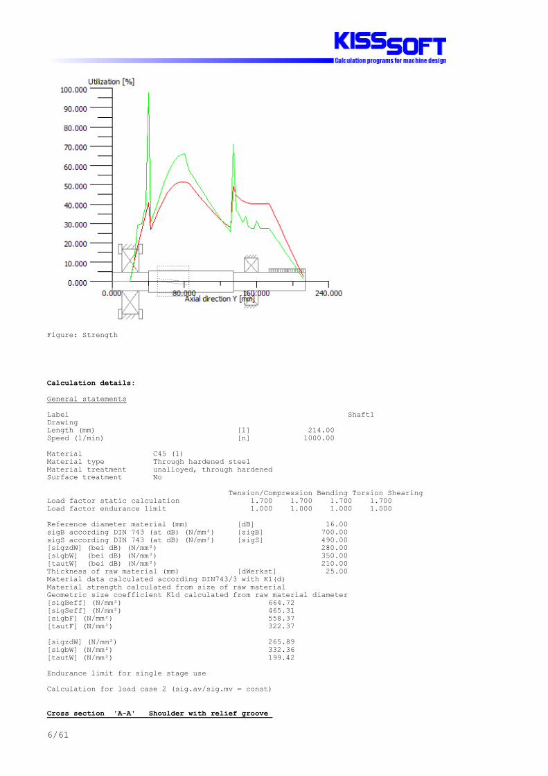
Figure: Strength
Calculation details:
General statements
Label Shaft1DrawingLength (mm) [l] 214.00Speed (1/min) [n] 1000.00
Material C45 (1)Material type Through hardened steelMaterial treatment unalloyed, through hardenedSurface treatment No
Tension/Compression Bending Torsion ShearingLoad factor static calculation 1.700 1.700 1.700 1.700Load factor endurance limit 1.000 1.000 1.000 1.000
Reference diameter material (mm) [dB] 16.00sigB according DIN 743 (at dB) (N/mm²) [sigB] 700.00sigS according DIN 743 (at dB) (N/mm²) [sigS] 490.00[sigzdW] (bei dB) (N/mm²) 280.00[sigbW] (bei dB) (N/mm²) 350.00[tautW] (bei dB) (N/mm²) 210.00Thickness of raw material (mm) [dWerkst] 25.00Material data calculated according DIN743/3 with K1(d)Material strength calculated from size of raw materialGeometric size coefficient K1d calculated from raw material diameter[sigBeff] (N/mm²) 664.72[sigSeff] (N/mm²) 465.31[sigbF] (N/mm²) 558.37[tautF] (N/mm²) 322.37
[sigzdW] (N/mm²) 265.89[sigbW] (N/mm²) 332.36[tautW] (N/mm²) 199.42
Endurance limit for single stage use
Calculation for load case 2 (sig.av/sig.mv = const)
Cross section 'A-A' Shoulder with relief groove

7/61
Comment Y= 40.00mmPosition (Y-Coordinate) (mm) [y] 40.00External diameter (mm) [da] 20.000Inner diameter (mm) [di] 0.000Notch effect Shoulder with relief groove[D, d, D1, r, t] (mm) 24.00 19.40 20.00 0.80 0.30Shape BMean roughness (µm) [Rz] 8.000
Tension/Compression Bending Torsion ShearingStress: (N) (Nm)Mean value 660.037 0.000 0.000 0.000Amplitude 660.037 84.311 0.000 4215.529Maximum value 2244.126 143.329 0.000 7166.399Cross section, moment of resistance: (mm²)[A, Wb, Wt, A] 295.592 716.81 1433.62 295.592
Stresses: (N/mm²)[sigzdm, sigbm, taum, tauqm] (N/mm²) 2.233 0.000 0.000 0.000[sigzda, sigba, taua, tauqa] (N/mm²) 2.233 117.620 0.000 19.015[sigzdmax,sigbmax,taumax,tauqmax] (N/mm²) 7.592 199.954 0.000 32.326
Technological size influence [K1(sigB)] 0.950 [K1(sigS)] 0.950
Tension/Compression Bending TorsionStress concentration factor [alfa] 2.649 2.346 1.629References stress slope [G'] 3.202 3.202 1.437support coefficient n [n] 1.186 1.186 1.125Notch effect coefficient [beta] 2.233 1.978 1.449Geometrical size influence [K2(d)] 1.000 0.935 0.935Influence coefficient surface roughness [KF] 0.896 0.896 0.940Influence coefficient surface strengthening [KV] 1.000 1.000 1.000Total influence coefficient [K] 2.349 2.232 1.614
Present margin of safety for endurance limit:Equivalent mean stress (N/mm²) [sigmV] 2.233Equivalent mean stress (N/mm²) [taumV] 1.289Fatigue limit of part (N/mm²) [sigWK] 113.192 148.893 123.587Influence coeff. mean stress sensitivity. [PsisigK] 0.093 0.126 0.102Possible amplitude (N/mm²) [sigADK] 103.554 148.538 0.250Margin of safety endurance limit [S] 1.229Required safety [Smin] 1.200Result (%) [S/Smin] 102.4
Present margin of safetyfor proof against exceed of yield point:Static support number [K2F] 1.000 1.200 1.200Increase coefficient [gammaF] 1.100 1.100 1.000Yield stress of part (N/mm²) [sigFK] 511.838 614.206 322.374Margin of safety yield stress [S] 2.938Required safety [Smin] 1.200Result (%) [S/Smin] 244.8
Cross section 'B-B' Shoulder with relief groove Comment Y= 134.00mmPosition (Y-Coordinate) (mm) [y] 134.00External diameter (mm) [da] 20.000Inner diameter (mm) [di] 0.000Notch effect Shoulder with relief groove[D, d, D1, r, t] (mm) 24.00 19.40 20.00 0.80 0.30Shape BMean roughness (µm) [Rz] 8.000
Tension/Compression Bending Torsion ShearingStress: (N) (Nm)Mean value 0.000 0.000 50.000 0.000Amplitude 0.000 48.338 50.000 2415.238Maximum value 0.000 82.174 170.000 4105.904Cross section, moment of resistance: (mm²)[A, Wb, Wt, A] 295.592 716.81 1433.62 295.592
Stresses: (N/mm²)[sigzdm, sigbm, taum, tauqm] (N/mm²) 0.000 0.000 34.877 0.000[sigzda, sigba, taua, tauqa] (N/mm²) 0.000 67.434 34.877 10.894[sigzdmax,sigbmax,taumax,tauqmax] (N/mm²) 0.000 114.638 118.581 18.521

8/61
Technological size influence [K1(sigB)] 0.950 [K1(sigS)] 0.950
Tension/Compression Bending TorsionStress concentration factor [alfa] 2.649 2.346 1.629References stress slope [G'] 3.202 3.202 1.437support coefficient n [n] 1.186 1.186 1.125Notch effect coefficient [beta] 2.233 1.978 1.449Geometrical size influence [K2(d)] 1.000 0.935 0.935Influence coefficient surface roughness [KF] 0.896 0.896 0.940Influence coefficient surface strengthening [KV] 1.000 1.000 1.000Total influence coefficient [K] 2.349 2.232 1.614
Present margin of safety for endurance limit:Equivalent mean stress (N/mm²) [sigmV] 60.408Equivalent mean stress (N/mm²) [taumV] 34.877Fatigue limit of part (N/mm²) [sigWK] 113.192 148.893 123.587Influence coeff. mean stress sensitivity. [PsisigK] 0.093 0.126 0.102Possible amplitude (N/mm²) [sigADK] 0.008 133.779 112.098Margin of safety endurance limit [S] 1.688Required safety [Smin] 1.200Result (%) [S/Smin] 140.7
Present margin of safetyfor proof against exceed of yield point:Static support number [K2F] 1.000 1.200 1.200Increase coefficient [gammaF] 1.100 1.100 1.000Yield stress of part (N/mm²) [sigFK] 511.838 614.206 322.374Margin of safety yield stress [S] 2.424Required safety [Smin] 1.200Result (%) [S/Smin] 202.0
Cross section 'C-C' Smooth shaft CommentPosition (Y-Coordinate) (mm) [y] 80.31External diameter (mm) [da] 24.000Inner diameter (mm) [di] 0.000Notch effect Smooth shaftMean roughness (µm) [Rz] 4.800
Tension/Compression Bending Torsion ShearingStress: (N) (Nm)Mean value 82.505 0.000 43.750 0.000Amplitude 82.505 175.199 43.750 1590.960Maximum value 280.516 297.838 148.750 2704.632Cross section, moment of resistance: (mm²)[A, Wb, Wt, A] 452.389 1357.17 2714.34 452.389
Stresses: (N/mm²)[sigzdm, sigbm, taum, tauqm] (N/mm²) 0.182 0.000 16.118 0.000[sigzda, sigba, taua, tauqa] (N/mm²) 0.182 129.091 16.118 4.689[sigzdmax,sigbmax,taumax,tauqmax] (N/mm²) 0.620 219.455 54.802 7.971
Technological size influence [K1(sigB)] 0.950 [K1(sigS)] 0.950
Tension/Compression Bending TorsionNotch effect coefficient [beta(dB)] 0.000 0.000 0.000[dB] (mm) = 0.0Geometrical size influence [K3(d)] 0.000 0.000 0.000Geometrical size influence [K3(dB)] 0.000 0.000 0.000Notch effect coefficient [beta] 1.000 1.000 1.000Geometrical size influence [K2(d)] 1.000 0.922 0.922Influence coefficient surface roughness [KF] 0.922 0.922 0.955Influence coefficient surface strengthening [KV] 1.000 1.000 1.000Total influence coefficient [K] 1.085 1.169 1.131
Present margin of safety for endurance limit:Equivalent mean stress (N/mm²) [sigmV] 27.918Equivalent mean stress (N/mm²) [taumV] 16.118Fatigue limit of part (N/mm²) [sigWK] 245.104 284.314 176.279Influence coeff. mean stress sensitivity. [PsisigK] 0.226 0.272 0.153Possible amplitude (N/mm²) [sigADK] 3.020 268.517 152.905

9/61
Margin of safety endurance limit [S] 1.814Required safety [Smin] 1.200Result (%) [S/Smin] 151.2
Present margin of safetyfor proof against exceed of yield point:Static support number [K2F] 1.000 1.200 1.200Increase coefficient [gammaF] 1.000 1.000 1.000Yield stress of part (N/mm²) [sigFK] 465.307 558.369 322.374Margin of safety yield stress [S] 2.329Required safety [Smin] 1.200Result (%) [S/Smin] 194.1
Cross section 'D-D' Smooth shaft CommentPosition (Y-Coordinate) (mm) [y] 37.10External diameter (mm) [da] 20.000Inner diameter (mm) [di] 0.000Notch effect Smooth shaftMean roughness (µm) [Rz] 4.800
Tension/Compression Bending Torsion ShearingStress: (N) (Nm)Mean value 660.037 0.000 0.000 0.000Amplitude 660.037 72.086 0.000 4215.448Maximum value 2244.126 122.546 0.000 7166.262Cross section, moment of resistance: (mm²)[A, Wb, Wt, A] 314.159 785.40 1570.80 314.159
Stresses: (N/mm²)[sigzdm, sigbm, taum, tauqm] (N/mm²) 2.101 0.000 0.000 0.000[sigzda, sigba, taua, tauqa] (N/mm²) 2.101 91.783 0.000 17.891[sigzdmax,sigbmax,taumax,tauqmax] (N/mm²) 7.143 156.031 0.000 30.415
Technological size influence [K1(sigB)] 0.950 [K1(sigS)] 0.950
Tension/Compression Bending TorsionNotch effect coefficient [beta(dB)] 0.000 0.000 0.000[dB] (mm) = 0.0Geometrical size influence [K3(d)] 0.000 0.000 0.000Geometrical size influence [K3(dB)] 0.000 0.000 0.000Notch effect coefficient [beta] 1.000 1.000 1.000Geometrical size influence [K2(d)] 1.000 0.935 0.935Influence coefficient surface roughness [KF] 0.922 0.922 0.955Influence coefficient surface strengthening [KV] 1.000 1.000 1.000Total influence coefficient [K] 1.085 1.155 1.117
Present margin of safety for endurance limit:Equivalent mean stress (N/mm²) [sigmV] 2.101Equivalent mean stress (N/mm²) [taumV] 1.213Fatigue limit of part (N/mm²) [sigWK] 245.104 287.791 178.508Influence coeff. mean stress sensitivity. [PsisigK] 0.226 0.276 0.155Possible amplitude (N/mm²) [sigADK] 199.915 285.982 0.266Margin of safety endurance limit [S] 3.017Required safety [Smin] 1.200Result (%) [S/Smin] 251.4
Present margin of safetyfor proof against exceed of yield point:Static support number [K2F] 1.000 1.200 1.200Increase coefficient [gammaF] 1.000 1.000 1.000Yield stress of part (N/mm²) [sigFK] 465.307 558.369 322.374Margin of safety yield stress [S] 3.392Required safety [Smin] 1.200Result (%) [S/Smin] 282.7
Cross section 'E-E' Smooth shaft CommentPosition (Y-Coordinate) (mm) [y] 137.40External diameter (mm) [da] 20.000Inner diameter (mm) [di] 0.000Notch effect Smooth shaftMean roughness (µm) [Rz] 4.800

10/61
Tension/Compression Bending Torsion ShearingStress: (N) (Nm)Mean value -0.000 0.000 50.000 0.000Amplitude 0.000 40.126 50.000 2415.155Maximum value -0.000 68.214 170.000 4105.763Cross section, moment of resistance: (mm²)[A, Wb, Wt, A] 314.159 785.40 1570.80 314.159
Stresses: (N/mm²)[sigzdm, sigbm, taum, tauqm] (N/mm²) -0.000 0.000 31.831 0.000[sigzda, sigba, taua, tauqa] (N/mm²) 0.000 51.090 31.831 10.250[sigzdmax,sigbmax,taumax,tauqmax] (N/mm²) -0.000 86.853 108.225 17.425
Technological size influence [K1(sigB)] 0.950 [K1(sigS)] 0.950
Tension/Compression Bending TorsionNotch effect coefficient [beta(dB)] 0.000 0.000 0.000[dB] (mm) = 0.0Geometrical size influence [K3(d)] 0.000 0.000 0.000Geometrical size influence [K3(dB)] 0.000 0.000 0.000Notch effect coefficient [beta] 1.000 1.000 1.000Geometrical size influence [K2(d)] 1.000 0.935 0.935Influence coefficient surface roughness [KF] 0.922 0.922 0.955Influence coefficient surface strengthening [KV] 1.000 1.000 1.000Total influence coefficient [K] 1.085 1.155 1.117
Present margin of safety for endurance limit:Equivalent mean stress (N/mm²) [sigmV] 55.133Equivalent mean stress (N/mm²) [taumV] 31.831Fatigue limit of part (N/mm²) [sigWK] 245.104 287.791 178.508Influence coeff. mean stress sensitivity. [PsisigK] 0.226 0.276 0.155Possible amplitude (N/mm²) [sigADK] 0.008 221.694 154.539Margin of safety endurance limit [S] 3.235Required safety [Smin] 1.200Result (%) [S/Smin] 269.6
Present margin of safetyfor proof against exceed of yield point:Static support number [K2F] 1.000 1.200 1.200Increase coefficient [gammaF] 1.000 1.000 1.000Yield stress of part (N/mm²) [sigFK] 465.307 558.369 322.374Margin of safety yield stress [S] 2.703Required safety [Smin] 1.200Result (%) [S/Smin] 225.2
Cross section 'F-F' Interference fit Comment Fit at bearing 2Position (Y-Coordinate) (mm) [y] 147.60External diameter (mm) [da] 20.000Inner diameter (mm) [di] 0.000Notch effect Interference fit Characteristics: Slight interference fitMean roughness (µm) [Rz] 4.800
Tension/Compression Bending Torsion ShearingStress: (N) (Nm)Mean value -0.000 0.000 50.000 0.000Amplitude 0.000 15.493 50.000 2414.930Maximum value -0.000 26.338 170.000 4105.381Cross section, moment of resistance: (mm²)[A, Wb, Wt, A] 314.159 785.40 1570.80 314.159
Stresses: (N/mm²)[sigzdm, sigbm, taum, tauqm] (N/mm²) -0.000 0.000 31.831 0.000[sigzda, sigba, taua, tauqa] (N/mm²) 0.000 19.726 31.831 10.249[sigzdmax,sigbmax,taumax,tauqmax] (N/mm²) -0.000 33.535 108.225 17.424
Technological size influence [K1(sigB)] 0.950 [K1(sigS)] 0.950
Tension/Compression Bending TorsionNotch effect coefficient [beta(dB)] 1.563 1.563 1.253[dB] (mm) = 20.0Geometrical size influence [K3(d)] 0.987 0.987 0.994Geometrical size influence [K3(dB)] 0.987 0.987 0.994

11/61
Notch effect coefficient [beta] 1.563 1.563 1.253Geometrical size influence [K2(d)] 1.000 0.935 0.935Influence coefficient surface roughness [KF] 1.000 1.000 1.000Roughness factor is included into the notch effect coefficientInfluence coefficient surface strengthening [KV] 1.000 1.000 1.000Total influence coefficient [K] 1.563 1.672 1.341
Present margin of safety for endurance limit:Equivalent mean stress (N/mm²) [sigmV] 55.133Equivalent mean stress (N/mm²) [taumV] 31.831Fatigue limit of part (N/mm²) [sigWK] 170.135 198.743 148.699Influence coeff. mean stress sensitivity. [PsisigK] 0.147 0.176 0.126Possible amplitude (N/mm²) [sigADK] 0.008 133.272 132.067Margin of safety endurance limit [S] 3.536Required safety [Smin] 1.200Result (%) [S/Smin] 294.6
Present margin of safetyfor proof against exceed of yield point:Static support number [K2F] 1.000 1.200 1.200Increase coefficient [gammaF] 1.000 1.000 1.000Yield stress of part (N/mm²) [sigFK] 465.307 558.369 322.374Margin of safety yield stress [S] 2.932Required safety [Smin] 1.200Result (%) [S/Smin] 244.3
Remarks:- The shearing force is not considered in the analysis according to DIN 743..- Cross section with square groove: The reference diameter for the notch number is not defined. Therefore the shaft diameter is taken as reference diameter..- Cross section with interference fit: The notching factor for the light fit case is no longer defined in DIN 743. The values are imported from the FKM-Guideline..
End report lines: 670

12/61
_O.GearBox.Shaft2.CalcShaft KISSsoft - Release 03-2011F KISSsoft evaluation
File Name : UnnamedChanged by : Harinder on: 12.08.2011 at: 13:11:29
Analysis of shafts, axle and beams
Input data
Coordinate system shaft: see picture W-002
Label Shaft2DrawingInitial position (mm) 0.000Length (mm) 174.000Speed (1/min) 200.00Sense of rotation: counter clockwise
Material C45 (1)Young's modulus (N/mm²) 206000.000Poisson's ratio nu 0.300Specific weight (kg/m³) 7830.000Warmth elongation coefficient (10^-6/K) 11.500Temperature (°C) 20.000Weight of shaft (kg) 1.622Mass moment of inertia (kgm²) 0.000Momentum of mass GD2 (Nm²) 0.012
Weight towards ( 0.000, 0.000,-1.000)Consider deformations due to shearingShear correction coefficient 1.100Contact angle of roller bearings is not consideredReference temperature (°C) 20.000
Figure: Load applications

13/61
SHAFT GEOMETRY, BEARING AND FORCES
Shaft 'Shaft2':
Cylinder outside ('') y= 0.00...40.00 (mm)d=35.00 (mm), l=40.00 (mm), Rz= 4.8
Relief groove (e)(r): r= 0.80 mm t= 0.30 mm l= 2.50 mm Rz= 8.0 y= 40.00 (mm) Form E (DIN 509), Series 1, with the usual stressing
Cylinder outside ('') y= 40.00...134.00 (mm)d=42.00 (mm), l=94.00 (mm), Rz= 4.8
Cylinder outside ('') y= 134.00...174.00 (mm)d=35.00 (mm), l=40.00 (mm), Rz= 4.8
Relief groove (e)(l): r= 0.80 mm t= 0.30 mm l= 2.50 mm Rz= 8.0 y= 134.00 (mm) Form E (DIN 509), Series 1, with the usual stressing
Cylindrical gear ('Gear2(c12)') y= 67.37 (mm)Reference diameter (mm) 166.6667Helix angle (°) 12.4081 leftPressure angle (°) 24.5984Position of contact point (°) 180.0000Width of force input (mm) 34.4970Power (kW) 10.2625 driven (Input)Torque (Nm) -490.0000Axial force (N) -1293.6727Shearing force X (N) 2756.2555Shearing force Z (N) -5879.9999Bending moment X (Nm) 0.0000Bending moment Z (Nm) 107.8061
Cylindrical gear ('Gear3(c34)') y= 115.61 (mm)Reference diameter (mm) 64.0000Helix angle (°) 16.3840 rightPressure angle (°) 23.3285Position of contact point (°) 0.0000Width of force input (mm) 35.8830Power (kW) 10.2625 driving (Output)Torque (Nm) 490.0000Axial force (N) -4502.0768Shearing force X (N) -6883.1419Shearing force Z (N) -15312.4997Bending moment X (Nm) 0.0000Bending moment Z (Nm) -144.0665
Fixed bearing ('Bearing1')Deep groove ball bearing (single row) (SKF 6407) y= 20.00 (mm)d = 35.00 (mm), D = 100.00 (mm), B = 25.00 (mm), r = 1.50 (mm)C = 55.300 kN, C0 = 31.000 kN, Cu = 1.290 kNBearing clearance DIN 620 C0 (13.00 µm)
Free bearing ('Bearing2')Deep groove ball bearing (single row) (SKF 6407) y= 154.00 (mm)d = 35.00 (mm), D = 100.00 (mm), B = 25.00 (mm), r = 1.50 (mm)C = 55.300 kN, C0 = 31.000 kN, Cu = 1.290 kNBearing clearance DIN 620 C0 (13.00 µm)
________________________________________________________________________
max. deflection 0.04086 mm (Shaft2, 91.14 (mm))
Center of massShaft2 87.0 mm
Probability of failure [n] 10.00 %Axial clearance [uA] 10.00 µmRoller bearings, classical calculation (contact angle not considered)
Shaft 'Shaft2' Roller bearing 'Bearing1'Position (Y-coordinate) [y] 20.00 mmEquivalent load [P] 12.18 kN

14/61
Equivalent load [P0] 8.21 kNLife modification factor for reliability[a1] 1.000Service life [Lnh] 7802.44 hstatic safety factor [S0] 3.78Bearing reaction force [Fx] 0.461 kNBearing reaction force [Fy] 5.796 kNBearing reaction force [Fz] 8.196 kNBearing reaction force [Fr] 8.209 kN (86.78°)Torque of friction [Mloss] 0.531 NmDisplacement of bearing [ux] -0.000 mmDisplacement of bearing [uy] -0.010 mmDisplacement of bearing [uz] -0.007 mmDisplacement of bearing [ur] 0.007 mm (-93.22°)Misalignment of bearing [rx] -0.641 mrad (-2.2')Misalignment of bearing [ry] 0.000 mrad (0')Misalignment of bearing [rz] 0.184 mrad (0.63')Misalignment of bearing [rr] 0.667 mrad (2.29')
Shaft 'Shaft2' Roller bearing 'Bearing2'Position (Y-coordinate) [y] 154.00 mmEquivalent load [P] 13.52 kNEquivalent load [P0] 13.52 kNLife modification factor for reliability[a1] 1.000Service life [Lnh] 5703.92 hstatic safety factor [S0] 2.29Bearing reaction force [Fx] 3.666 kNBearing reaction force [Fy] 0.000 kNBearing reaction force [Fz] 13.012 kNBearing reaction force [Fr] 13.519 kN (74.26°)Torque of friction [Mloss] 0.555 NmDisplacement of bearing [ux] -0.002 mmDisplacement of bearing [uy] -0.012 mmDisplacement of bearing [uz] -0.006 mmDisplacement of bearing [ur] 0.007 mm (-105.74°)Misalignment of bearing [rx] 0.745 mrad (2.56')Misalignment of bearing [ry] 0.977 mrad (3.36')Misalignment of bearing [rz] -0.257 mrad (-0.88')Misalignment of bearing [rr] 0.788 mrad (2.71')
Figure: Displacement (bending etc.) (Arbitrary plane 72.9505654 °)

15/61
GEH(von Mises): sigV = ((sigB+sigZ,D)^2 + 3*(tauT+tauS)^2)^1/2
Figure: Equivalent stress

16/61
Strength calculation according to DIN 743 (Edition 2000-10)
Summary
Label Shaft2Drawing
Material C45 (1)Material type Through hardened steelMaterial treatment unalloyed, through hardenedSurface treatment No
Calculation of endurance limit and the static strengthCalculation for load case 2 (sig.av/sig.mv = const)
Cross section Position (Y-Coord) (mm) A-A 134.00 Shoulder with relief groove B-B 97.67 Smooth shaft C-C 40.00 Shoulder with relief grooveResults: Cross section Kfb Kfsig K2d SD SS A-A 2.29 0.90 0.90 1.72 4.97 B-B 1.00 0.93 0.88 2.53 3.46 C-C 2.29 0.90 0.90 2.62 9.91
Nominal safety: 1.20 1.20
Abbreviations:Kfb: Notch factor bendingKfsig: Surface factorK2d: Size coefficient bendingSD: Safety endurance limitSS: Safety against yield point
The requirements of the safety proof of the shaft are:
satisfied [x] not satisfied [ ]
Design engineer:................... Date:........... Signature:......
17/61
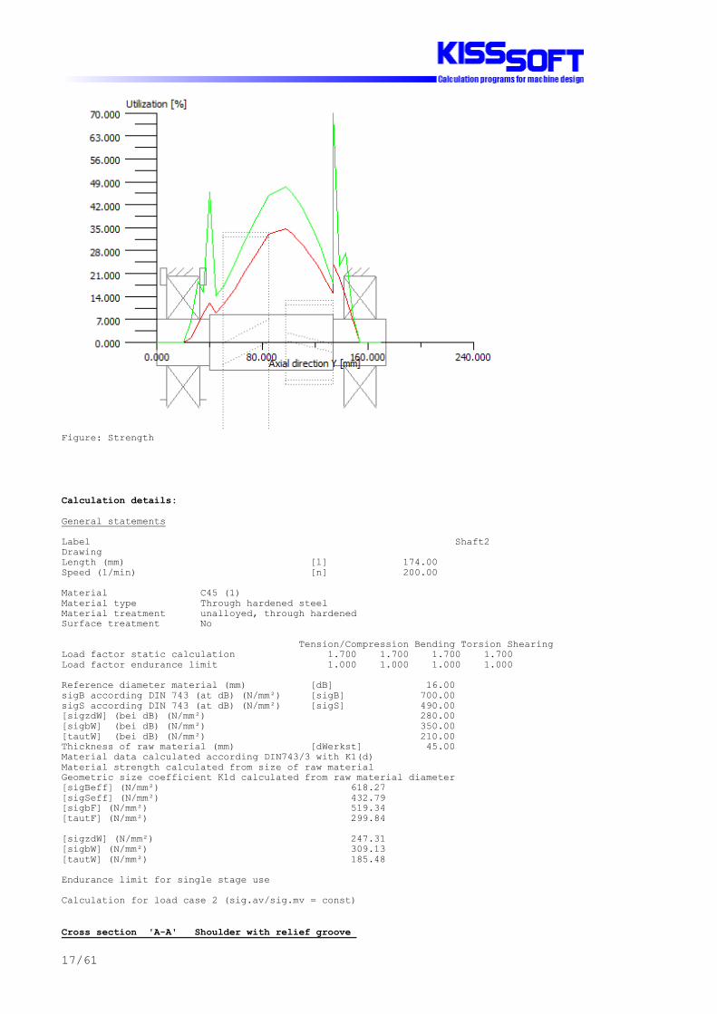
Figure: Strength
Calculation details:
General statements
Label Shaft2DrawingLength (mm) [l] 174.00Speed (1/min) [n] 200.00
Material C45 (1)Material type Through hardened steelMaterial treatment unalloyed, through hardenedSurface treatment No
Tension/Compression Bending Torsion ShearingLoad factor static calculation 1.700 1.700 1.700 1.700Load factor endurance limit 1.000 1.000 1.000 1.000
Reference diameter material (mm) [dB] 16.00sigB according DIN 743 (at dB) (N/mm²) [sigB] 700.00sigS according DIN 743 (at dB) (N/mm²) [sigS] 490.00[sigzdW] (bei dB) (N/mm²) 280.00[sigbW] (bei dB) (N/mm²) 350.00[tautW] (bei dB) (N/mm²) 210.00Thickness of raw material (mm) [dWerkst] 45.00Material data calculated according DIN743/3 with K1(d)Material strength calculated from size of raw materialGeometric size coefficient K1d calculated from raw material diameter[sigBeff] (N/mm²) 618.27[sigSeff] (N/mm²) 432.79[sigbF] (N/mm²) 519.34[tautF] (N/mm²) 299.84
[sigzdW] (N/mm²) 247.31[sigbW] (N/mm²) 309.13[tautW] (N/mm²) 185.48
Endurance limit for single stage use
Calculation for load case 2 (sig.av/sig.mv = const)
Cross section 'A-A' Shoulder with relief groove

18/61
Comment Y= 134.00mmPosition (Y-Coordinate) (mm) [y] 134.00External diameter (mm) [da] 35.000Inner diameter (mm) [di] 0.000Notch effect Shoulder with relief groove[D, d, D1, r, t] (mm) 42.00 34.40 35.00 0.80 0.30Shape BMean roughness (µm) [Rz] 8.000
Tension/Compression Bending Torsion ShearingStress: (N) (Nm)Mean value -0.0 0.0 0.0 0.0Amplitude 0.0 270.3 0.0 13516.0Maximum value -0.0 459.5 0.0 22977.2Cross section, moment of resistance: (mm²)[A, Wb, Wt, A] 929.4 3996 7993 929.4
Stresses: (N/mm²)[sigzdm, sigbm, taum, tauqm] (N/mm²) -0.000 0.000 0.000 0.000[sigzda, sigba, taua, tauqa] (N/mm²) 0.000 67.640 0.000 19.390[sigzdmax,sigbmax,taumax,tauqmax] (N/mm²) -0.000 114.988 0.000 32.963
Technological size influence [K1(sigB)] 0.883 [K1(sigS)] 0.883
Tension/Compression Bending TorsionStress concentration factor [alfa] 3.118 2.758 1.833References stress slope [G'] 3.143 3.143 1.437support coefficient n [n] 1.205 1.205 1.138Notch effect coefficient [beta] 2.589 2.290 1.610Geometrical size influence [K2(d)] 1.000 0.897 0.897Influence coefficient surface roughness [KF] 0.903 0.903 0.944Influence coefficient surface strengthening [KV] 1.000 1.000 1.000Total influence coefficient [K] 2.697 2.660 1.854
Present margin of safety for endurance limit:Equivalent mean stress (N/mm²) [sigmV] 0.000Equivalent mean stress (N/mm²) [taumV] 0.000Fatigue limit of part (N/mm²) [sigWK] 91.704 116.218 100.035Influence coeff. mean stress sensitivity. [PsisigK] 0.080 0.104 0.088Possible amplitude (N/mm²) [sigADK] 91.704 116.218 100.035Margin of safety endurance limit [S] 1.718Required safety [Smin] 1.200Result (%) [S/Smin] 143.2
Present margin of safetyfor proof against exceed of yield point:Static support number [K2F] 1.000 1.200 1.200Increase coefficient [gammaF] 1.150 1.100 1.000Yield stress of part (N/mm²) [sigFK] 497.703 571.277 299.843Margin of safety yield stress [S] 4.968Required safety [Smin] 1.200Result (%) [S/Smin] 414.0
Cross section 'B-B' Smooth shaft CommentPosition (Y-Coordinate) (mm) [y] 97.67External diameter (mm) [da] 42.000Inner diameter (mm) [di] 0.000Notch effect Smooth shaftMean roughness (µm) [Rz] 4.800
Tension/Compression Bending Torsion ShearingStress: (N) (Nm)Mean value -2251.0 0.0 245.0 0.0Amplitude 2251.0 511.2 245.0 3958.9Maximum value -7653.5 869.1 833.0 6730.2Cross section, moment of resistance: (mm²)[A, Wb, Wt, A] 1385.4 7274 14547 1385.4
Stresses: (N/mm²)[sigzdm, sigbm, taum, tauqm] (N/mm²) -1.625 0.000 16.842 0.000[sigzda, sigba, taua, tauqa] (N/mm²) 1.625 70.287 16.842 3.810[sigzdmax,sigbmax,taumax,tauqmax] (N/mm²) -5.524 119.489 57.262 6.477
Technological size influence [K1(sigB)] 0.883

19/61
[K1(sigS)] 0.883
Tension/Compression Bending TorsionNotch effect coefficient [beta(dB)] 0.000 0.000 0.000[dB] (mm) = 0.0Geometrical size influence [K3(d)] 0.000 0.000 0.000Geometrical size influence [K3(dB)] 0.000 0.000 0.000Notch effect coefficient [beta] 1.000 1.000 1.000Geometrical size influence [K2(d)] 1.000 0.885 0.885Influence coefficient surface roughness [KF] 0.927 0.927 0.958Influence coefficient surface strengthening [KV] 1.000 1.000 1.000Total influence coefficient [K] 1.079 1.209 1.174
Present margin of safety for endurance limit:Equivalent mean stress (N/mm²) [sigmV] 29.216Equivalent mean stress (N/mm²) [taumV] 16.868Fatigue limit of part (N/mm²) [sigWK] 229.139 255.641 157.981Influence coeff. mean stress sensitivity. [PsisigK] 0.227 0.261 0.146Possible amplitude (N/mm²) [sigADK] 22.867 230.724 137.770Margin of safety endurance limit [S] 2.531Required safety [Smin] 1.200Result (%) [S/Smin] 210.9
Present margin of safetyfor proof against exceed of yield point:Static support number [K2F] 1.000 1.200 1.200Increase coefficient [gammaF] 1.000 1.000 1.000Yield stress of part (N/mm²) [sigFK] 432.786 519.343 299.843Margin of safety yield stress [S] 3.457Required safety [Smin] 1.200Result (%) [S/Smin] 288.0
Cross section 'C-C' Shoulder with relief groove Comment Y= 40.00mmPosition (Y-Coordinate) (mm) [y] 40.00External diameter (mm) [da] 35.000Inner diameter (mm) [di] 0.000Notch effect Shoulder with relief groove[D, d, D1, r, t] (mm) 42.00 34.40 35.00 0.80 0.30Shape BMean roughness (µm) [Rz] 8.000
Tension/Compression Bending Torsion ShearingStress: (N) (Nm)Mean value -2897.9 0.0 0.0 0.0Amplitude 2897.9 164.1 0.0 8206.3Maximum value -9852.8 279.0 0.0 13950.7Cross section, moment of resistance: (mm²)[A, Wb, Wt, A] 929.4 3996 7993 929.4
Stresses: (N/mm²)[sigzdm, sigbm, taum, tauqm] (N/mm²) -3.118 0.000 0.000 0.000[sigzda, sigba, taua, tauqa] (N/mm²) 3.118 41.067 0.000 11.773[sigzdmax,sigbmax,taumax,tauqmax] (N/mm²) -10.601 69.814 0.000 20.014
Technological size influence [K1(sigB)] 0.883 [K1(sigS)] 0.883
Tension/Compression Bending TorsionStress concentration factor [alfa] 3.118 2.758 1.833References stress slope [G'] 3.143 3.143 1.437support coefficient n [n] 1.205 1.205 1.138Notch effect coefficient [beta] 2.589 2.290 1.610Geometrical size influence [K2(d)] 1.000 0.897 0.897Influence coefficient surface roughness [KF] 0.903 0.903 0.944Influence coefficient surface strengthening [KV] 1.000 1.000 1.000Total influence coefficient [K] 2.697 2.660 1.854
Present margin of safety for endurance limit:Equivalent mean stress (N/mm²) [sigmV] 3.118Equivalent mean stress (N/mm²) [taumV] 1.800Fatigue limit of part (N/mm²) [sigWK] 91.704 116.218 100.035Influence coeff. mean stress sensitivity. [PsisigK] 0.080 0.104 0.088Possible amplitude (N/mm²) [sigADK] 99.690 117.140 100.035

20/61
Margin of safety endurance limit [S] 2.619Required safety [Smin] 1.200Result (%) [S/Smin] 218.2
Present margin of safetyfor proof against exceed of yield point:Static support number [K2F] 1.000 1.200 1.200Increase coefficient [gammaF] 1.150 1.100 1.000Yield stress of part (N/mm²) [sigFK] 497.703 571.277 299.843Margin of safety yield stress [S] 9.910Required safety [Smin] 1.200Result (%) [S/Smin] 825.8
Remarks:- The shearing force is not considered in the analysis according to DIN 743..- Cross section with square groove: The reference diameter for the notch number is not defined. Therefore the shaft diameter is taken as reference diameter..- Cross section with interference fit: The notching factor for the light fit case is no longer defined in DIN 743. The values are imported from the FKM-Guideline..
End report lines: 483

21/61
_O.GearBox.Shaft3.CalcShaft KISSsoft - Release 03-2011F KISSsoft evaluation
File Name : UnnamedChanged by : Harinder on: 12.08.2011 at: 13:11:31
Important hint: At least one warning has occurred during the calculation:1-> The static margin of safety of bearing 'Shaft 'Shaft3', Roller bearing 'Bearing1'' is low (in range0.5 - 2.0).
Please check whether these values are acceptable or not.
2-> The static margin of safety of bearing 'Shaft 'Shaft3', Roller bearing 'Bearing2'' is low (in range0.5 - 2.0).
Please check whether these values are acceptable or not.
Analysis of shafts, axle and beams
Input data
Coordinate system shaft: see picture W-002
Label Shaft3DrawingInitial position (mm) 0.000Length (mm) 174.000Speed (1/min) 59.26Sense of rotation: clockwise
Material C45 (1)Young's modulus (N/mm²) 206000.000Poisson's ratio nu 0.300Specific weight (kg/m³) 7830.000Warmth elongation coefficient (10^-6/K) 11.500Temperature (°C) 20.000Weight of shaft (kg) 3.194Mass moment of inertia (kgm²) 0.001Momentum of mass GD2 (Nm²) 0.049
Weight towards ( 0.000, 0.000,-1.000)Consider deformations due to shearingShear correction coefficient 1.100Contact angle of roller bearings is not consideredReference temperature (°C) 20.000

22/61
Figure: Load applications
SHAFT GEOMETRY, BEARING AND FORCES
Shaft 'Shaft3':
Cylinder outside ('') y= 0.00...40.00 (mm)d=50.00 (mm), l=40.00 (mm), Rz= 4.8
Relief groove (e)(r): r= 0.80 mm t= 0.30 mm l= 2.50 mm Rz= 8.0 y= 40.00 (mm) Form E (DIN 509), Series 1, with the usual stressing
Cylinder outside ('') y= 40.00...134.00 (mm)d=60.00 (mm), l=94.00 (mm), Rz= 4.8
Cylinder outside ('') y= 134.00...174.00 (mm)d=45.00 (mm), l=40.00 (mm), Rz= 4.8
Relief groove (e)(l): r= 0.80 mm t= 0.30 mm l= 2.50 mm Rz= 8.0 y= 134.00 (mm) Form E (DIN 509), Series 1, with the usual stressing
Cylindrical gear ('Gear4(c34)') y= 115.61 (mm)Reference diameter (mm) 216.0000Helix angle (°) 16.3840 leftPressure angle (°) 23.3285Position of contact point (°) 180.0000Width of force input (mm) 35.8830Power (kW) 10.0573 driven (Input)Torque (Nm) 1620.6750Axial force (N) 4412.0353Shearing force X (N) 6745.4791Shearing force Z (N) 15006.2497Bending moment X (Nm) -0.0000Bending moment Z (Nm) -476.4998
Cylindrical gear ('Gear5(c56)') y= 67.37 (mm)Reference diameter (mm) 86.2687Helix angle (°) 14.4913 leftPressure angle (°) 24.7035Position of contact point (°) 0.0000Width of force input (mm) 53.4090Power (kW) 10.0573 driving (Output)

23/61
Torque (Nm) -1620.6750Axial force (N) -9710.8797Shearing force X (N) -17852.2663Shearing force Z (N) 37572.7415Bending moment X (Nm) 0.0000Bending moment Z (Nm) -418.8723
Fixed bearing ('Bearing1')Deep groove ball bearing (single row) (SKF 6410) y= 20.00 (mm)d = 50.00 (mm), D = 130.00 (mm), B = 31.00 (mm), r = 2.10 (mm)C = 87.100 kN, C0 = 52.000 kN, Cu = 2.200 kNBearing clearance DIN 620 C0 (14.50 µm)
Free bearing ('Bearing2')Deep groove ball bearing (single row) (SKF 6409) y= 154.00 (mm)d = 45.00 (mm), D = 120.00 (mm), B = 29.00 (mm), r = 2.00 (mm)C = 76.100 kN, C0 = 45.000 kN, Cu = 1.900 kNBearing clearance DIN 620 C0 (14.50 µm)
________________________________________________________________________
max. deflection 0.03186 mm (Shaft3, 80.72 (mm))
Center of massShaft3 84.5 mm
Probability of failure [n] 10.00 %Axial clearance [uA] 10.00 µmRoller bearings, classical calculation (contact angle not considered)
Shaft 'Shaft3' Roller bearing 'Bearing1'Position (Y-coordinate) [y] 20.00 mmEquivalent load [P] 32.89 kNEquivalent load [P0] 32.89 kNLife modification factor for reliability[a1] 1.000Service life [Lnh] 5223.18 hstatic safety factor [S0] 1.58Bearing reaction force [Fx] 16.290 kNBearing reaction force [Fy] 5.299 kNBearing reaction force [Fz] -28.573 kNBearing reaction force [Fr] 32.891 kN (-60.31°)Torque of friction [Mloss] 2.119 NmDisplacement of bearing [ux] -0.004 mmDisplacement of bearing [uy] -0.010 mmDisplacement of bearing [uz] 0.006 mmDisplacement of bearing [ur] 0.007 mm (119.69°)Misalignment of bearing [rx] 0.449 mrad (1.54')Misalignment of bearing [ry] 0.000 mrad (0')Misalignment of bearing [rz] 0.085 mrad (0.29')Misalignment of bearing [rr] 0.457 mrad (1.57')
Shaft 'Shaft3' Roller bearing 'Bearing2'Position (Y-coordinate) [y] 154.00 mmEquivalent load [P] 24.53 kNEquivalent load [P0] 24.53 kNLife modification factor for reliability[a1] 1.000Service life [Lnh] 8398.81 hstatic safety factor [S0] 1.83Bearing reaction force [Fx] -5.184 kNBearing reaction force [Fy] 0.000 kNBearing reaction force [Fz] -23.975 kNBearing reaction force [Fr] 24.529 kN (-102.2°)Torque of friction [Mloss] 1.348 NmDisplacement of bearing [ux] 0.002 mmDisplacement of bearing [uy] -0.010 mmDisplacement of bearing [uz] 0.007 mmDisplacement of bearing [ur] 0.007 mm (77.8°)Misalignment of bearing [rx] -0.434 mrad (-1.49')Misalignment of bearing [ry] 0.776 mrad (2.67')Misalignment of bearing [rz] -0.138 mrad (-0.47')Misalignment of bearing [rr] 0.456 mrad (1.57')

24/61
Figure: Displacement (bending etc.) (Arbitrary plane -75.4257344 °)
GEH(von Mises): sigV = ((sigB+sigZ,D)^2 + 3*(tauT+tauS)^2)^1/2
Figure: Equivalent stress

25/61
Strength calculation according to DIN 743 (Edition 2000-10)
Summary
Label Shaft3Drawing
Material C45 (1)Material type Through hardened steelMaterial treatment unalloyed, through hardenedSurface treatment No
Calculation of endurance limit and the static strengthCalculation for load case 2 (sig.av/sig.mv = const)
Cross section Position (Y-Coord) (mm) A-A 40.00 Shoulder with relief groove B-B 134.00 Shoulder with relief groove C-C 94.08 Smooth shaftResults: Cross section Kfb Kfsig K2d SD SS A-A 2.53 0.91 0.87 1.72 6.41 B-B 2.51 0.91 0.88 1.75 5.86 C-C 1.00 0.93 0.86 2.65 3.34
Nominal safety: 1.20 1.20
Abbreviations:Kfb: Notch factor bendingKfsig: Surface factorK2d: Size coefficient bendingSD: Safety endurance limitSS: Safety against yield point
The requirements of the safety proof of the shaft are:
satisfied [x] not satisfied [ ]
Design engineer:................... Date:........... Signature:......

26/61
Figure: Strength
Calculation details:
General statements
Label Shaft3DrawingLength (mm) [l] 174.00Speed (1/min) [n] 59.26
Material C45 (1)Material type Through hardened steelMaterial treatment unalloyed, through hardenedSurface treatment No
Tension/Compression Bending Torsion ShearingLoad factor static calculation 1.700 1.700 1.700 1.700Load factor endurance limit 1.000 1.000 1.000 1.000
Reference diameter material (mm) [dB] 16.00sigB according DIN 743 (at dB) (N/mm²) [sigB] 700.00sigS according DIN 743 (at dB) (N/mm²) [sigS] 490.00[sigzdW] (bei dB) (N/mm²) 280.00[sigbW] (bei dB) (N/mm²) 350.00[tautW] (bei dB) (N/mm²) 210.00Thickness of raw material (mm) [dWerkst] 65.00Material data calculated according DIN743/3 with K1(d)Material strength calculated from size of raw materialGeometric size coefficient K1d calculated from raw material diameter[sigBeff] (N/mm²) 589.20[sigSeff] (N/mm²) 412.44[sigbF] (N/mm²) 494.93[tautF] (N/mm²) 285.75
[sigzdW] (N/mm²) 235.68[sigbW] (N/mm²) 294.60[tautW] (N/mm²) 176.76
Endurance limit for single stage use
Calculation for load case 2 (sig.av/sig.mv = const)
Cross section 'A-A' Shoulder with relief groove

27/61
Comment Y= 40.00mmPosition (Y-Coordinate) (mm) [y] 40.00External diameter (mm) [da] 50.000Inner diameter (mm) [di] 0.000Notch effect Shoulder with relief groove[D, d, D1, r, t] (mm) 60.00 49.40 50.00 0.80 0.30Shape BMean roughness (µm) [Rz] 8.000
Tension/Compression Bending Torsion ShearingStress: (N) (Nm)Mean value -2649.4 0.0 0.0 0.0Amplitude 2649.4 657.9 0.0 32895.3Maximum value -9008.0 1118.5 0.0 55922.0Cross section, moment of resistance: (mm²)[A, Wb, Wt, A] 1916.7 11835 23671 1916.7
Stresses: (N/mm²)[sigzdm, sigbm, taum, tauqm] (N/mm²) -1.382 0.000 0.000 0.000[sigzda, sigba, taua, tauqa] (N/mm²) 1.382 55.589 0.000 22.884[sigzdmax,sigbmax,taumax,tauqmax] (N/mm²) -4.700 94.501 0.000 38.903
Technological size influence [K1(sigB)] 0.842 [K1(sigS)] 0.842
Tension/Compression Bending TorsionStress concentration factor [alfa] 3.484 3.077 1.994References stress slope [G'] 3.109 3.109 1.437support coefficient n [n] 1.217 1.217 1.148Notch effect coefficient [beta] 2.862 2.528 1.738Geometrical size influence [K2(d)] 1.000 0.873 0.873Influence coefficient surface roughness [KF] 0.907 0.907 0.946Influence coefficient surface strengthening [KV] 1.000 1.000 1.000Total influence coefficient [K] 2.965 2.997 2.046
Present margin of safety for endurance limit:Equivalent mean stress (N/mm²) [sigmV] 1.382Equivalent mean stress (N/mm²) [taumV] 0.798Fatigue limit of part (N/mm²) [sigWK] 79.481 98.287 86.388Influence coeff. mean stress sensitivity. [PsisigK] 0.072 0.091 0.079Possible amplitude (N/mm²) [sigADK] 85.678 98.510 86.388Margin of safety endurance limit [S] 1.723Required safety [Smin] 1.200Result (%) [S/Smin] 143.6
Present margin of safetyfor proof against exceed of yield point:Static support number [K2F] 1.000 1.200 1.200Increase coefficient [gammaF] 1.150 1.150 1.000Yield stress of part (N/mm²) [sigFK] 474.306 569.167 285.747Margin of safety yield stress [S] 6.405Required safety [Smin] 1.200Result (%) [S/Smin] 533.8
Cross section 'B-B' Shoulder with relief groove Comment Y= 134.00mmPosition (Y-Coordinate) (mm) [y] 134.00External diameter (mm) [da] 45.000Inner diameter (mm) [di] 0.000Notch effect Shoulder with relief groove[D, d, D1, r, t] (mm) 60.00 44.40 45.00 0.80 0.30Shape BMean roughness (µm) [Rz] 8.000
Tension/Compression Bending Torsion ShearingStress: (N) (Nm)Mean value -0.0 0.0 0.0 0.0Amplitude 0.0 490.7 0.0 24533.6Maximum value -0.0 834.1 0.0 41707.2Cross section, moment of resistance: (mm²)[A, Wb, Wt, A] 1548.3 8593 17186 1548.3
Stresses: (N/mm²)[sigzdm, sigbm, taum, tauqm] (N/mm²) -0.000 0.000 0.000 0.000[sigzda, sigba, taua, tauqa] (N/mm²) 0.000 57.101 0.000 21.127[sigzdmax,sigbmax,taumax,tauqmax] (N/mm²) -0.000 97.071 0.000 35.916

28/61
Technological size influence [K1(sigB)] 0.842 [K1(sigS)] 0.842
Tension/Compression Bending TorsionStress concentration factor [alfa] 3.516 3.048 2.035References stress slope [G'] 3.073 3.073 1.437support coefficient n [n] 1.216 1.216 1.148Notch effect coefficient [beta] 2.891 2.507 1.773Geometrical size influence [K2(d)] 1.000 0.880 0.880Influence coefficient surface roughness [KF] 0.907 0.907 0.946Influence coefficient surface strengthening [KV] 1.000 1.000 1.000Total influence coefficient [K] 2.994 2.950 2.071
Present margin of safety for endurance limit:Equivalent mean stress (N/mm²) [sigmV] 0.000Equivalent mean stress (N/mm²) [taumV] 0.000Fatigue limit of part (N/mm²) [sigWK] 78.721 99.860 85.347Influence coeff. mean stress sensitivity. [PsisigK] 0.072 0.093 0.078Possible amplitude (N/mm²) [sigADK] 78.721 99.860 85.347Margin of safety endurance limit [S] 1.749Required safety [Smin] 1.200Result (%) [S/Smin] 145.7
Present margin of safetyfor proof against exceed of yield point:Static support number [K2F] 1.000 1.200 1.200Increase coefficient [gammaF] 1.150 1.150 1.000Yield stress of part (N/mm²) [sigFK] 474.306 569.167 285.747Margin of safety yield stress [S] 5.863Required safety [Smin] 1.200Result (%) [S/Smin] 488.6
Cross section 'C-C' Smooth shaft CommentPosition (Y-Coordinate) (mm) [y] 94.08External diameter (mm) [da] 60.000Inner diameter (mm) [di] 0.000Notch effect Smooth shaftMean roughness (µm) [Rz] 4.800
Tension/Compression Bending Torsion ShearingStress: (N) (Nm)Mean value 2206.0 0.0 810.3 0.0Amplitude 2206.0 1159.5 810.3 9117.6Maximum value 7500.5 1971.1 2755.1 15499.9Cross section, moment of resistance: (mm²)[A, Wb, Wt, A] 2827.4 21206 42412 2827.4
Stresses: (N/mm²)[sigzdm, sigbm, taum, tauqm] (N/mm²) 0.780 0.000 19.107 0.000[sigzda, sigba, taua, tauqa] (N/mm²) 0.780 54.677 19.107 4.300[sigzdmax,sigbmax,taumax,tauqmax] (N/mm²) 2.653 92.951 64.962 7.309
Technological size influence [K1(sigB)] 0.842 [K1(sigS)] 0.842
Tension/Compression Bending TorsionNotch effect coefficient [beta(dB)] 0.000 0.000 0.000[dB] (mm) = 0.0Geometrical size influence [K3(d)] 0.000 0.000 0.000Geometrical size influence [K3(dB)] 0.000 0.000 0.000Notch effect coefficient [beta] 1.000 1.000 1.000Geometrical size influence [K2(d)] 1.000 0.861 0.861Influence coefficient surface roughness [KF] 0.930 0.930 0.960Influence coefficient surface strengthening [KV] 1.000 1.000 1.000Total influence coefficient [K] 1.076 1.237 1.203
Present margin of safety for endurance limit:Equivalent mean stress (N/mm²) [sigmV] 33.103Equivalent mean stress (N/mm²) [taumV] 19.112Fatigue limit of part (N/mm²) [sigWK] 219.106 238.185 146.890Influence coeff. mean stress sensitivity. [PsisigK] 0.228 0.253 0.142Possible amplitude (N/mm²) [sigADK] 9.497 206.512 128.575

29/61
Margin of safety endurance limit [S] 2.650Required safety [Smin] 1.200Result (%) [S/Smin] 220.8
Present margin of safetyfor proof against exceed of yield point:Static support number [K2F] 1.000 1.200 1.200Increase coefficient [gammaF] 1.000 1.000 1.000Yield stress of part (N/mm²) [sigFK] 412.440 494.928 285.747Margin of safety yield stress [S] 3.344Required safety [Smin] 1.200Result (%) [S/Smin] 278.7
Remarks:- The shearing force is not considered in the analysis according to DIN 743..- Cross section with square groove: The reference diameter for the notch number is not defined. Therefore the shaft diameter is taken as reference diameter..- Cross section with interference fit: The notching factor for the light fit case is no longer defined in DIN 743. The values are imported from the FKM-Guideline..
End report lines: 483

30/61
_O.GearBox.Shaft4.CalcShaft KISSsoft - Release 03-2011F KISSsoft evaluation
File Name : UnnamedChanged by : Amandeep on: 12.08.2011 at: 13:11:33
Important hint: At least one warning has occurred during the calculation:1-> The static margin of safety of bearing 'Shaft 'Shaft4', Roller bearing 'Bearing1'' is low (in range0.5 - 2.0).
Please check whether these values are acceptable or not.
2-> The static margin of safety of bearing 'Shaft 'Shaft4', Roller bearing 'Bearing2'' is low (in range0.5 - 2.0).
Please check whether these values are acceptable or not.
3-> Notching factor for- Light fit- Interference fit with reduction of pressureare no longer defined in DIN743 .The values correspond to the FKM-Guideline.
4-> Notching factor for- Light fit- Interference fit with reduction of pressureare no longer defined in DIN743 .The values correspond to the FKM-Guideline.
Analysis of shafts, axle and beams
Input data
Coordinate system shaft: see picture W-002
Label Shaft4DrawingInitial position (mm) 0.000Length (mm) 214.000Speed (1/min) 20.15Sense of rotation: counter clockwise
Material C45 (1)Young's modulus (N/mm²) 206000.000Poisson's ratio nu 0.300Specific weight (kg/m³) 7830.000Warmth elongation coefficient (10^-6/K) 11.500Temperature (°C) 20.000Weight of shaft (kg) 5.653Mass moment of inertia (kgm²) 0.003Momentum of mass GD2 (Nm²) 0.123
Weight towards ( 0.000, 0.000,-1.000)Consider deformations due to shearingShear correction coefficient 1.100Contact angle of roller bearings is not consideredReference temperature (°C) 20.000

31/61
Figure: Load applications
SHAFT GEOMETRY, BEARING AND FORCES
Shaft 'Shaft4':
Cylinder outside ('') y= 0.00...40.00 (mm)d=60.00 (mm), l=40.00 (mm), Rz= 4.8
Relief groove (e)(r): r= 0.80 mm t= 0.30 mm l= 2.50 mm Rz= 8.0 y= 40.00 (mm) Form E (DIN 509), Series 1, with the usual stressing
Cylinder outside ('') y= 40.00...134.00 (mm)d=72.00 (mm), l=94.00 (mm), Rz= 4.8
Cylinder outside ('') y= 134.00...214.00 (mm)d=60.00 (mm), l=80.00 (mm), Rz= 4.8
Relief groove (e)(l): r= 0.80 mm t= 0.30 mm l= 2.50 mm Rz= 8.0 y= 134.00 (mm) Form E (DIN 509), Series 1, with the usual stressing
Centric force ('CentricalLoad') y= 194.00 (mm)Width of force input (mm) 0.0000
Torque (Nm) 0.0000
Coupling ('Coupling(Boundary2)') y= 194.00 (mm)Eff. Diameter (mm) 60.0000Radial force coefficient (-) 0.0000Direction of radial force (°) 0.0000Axial force coefficient (-) 0.0000Width of force input (mm) 40.0000Power (kW) 9.8561 driving (Output)Torque (Nm) 4671.3574Mass (kg) 0.0000
Cylindrical gear ('Gear6(c56)') y= 67.37 (mm)Reference diameter (mm) 253.7313Helix angle (°) 14.4913 rightPressure angle (°) 24.7035Position of contact point (°) 180.0000

32/61
Width of force input (mm) 53.4090Power (kW) 9.8561 driven (Input)Torque (Nm) -4671.3574Axial force (N) 9516.6621Shearing force X (N) 17495.2210Shearing force Z (N) -36821.2867Bending moment X (Nm) -0.0000Bending moment Z (Nm) -1207.3378
Fixed bearing ('Bearing1')Deep groove ball bearing (single row) (SKF *6212) y= 20.00 (mm)d = 60.00 (mm), D = 110.00 (mm), B = 22.00 (mm), r = 1.50 (mm)C = 55.300 kN, C0 = 36.000 kN, Cu = 1.530 kNBearing clearance DIN 620 C0 (18.00 µm)
Free bearing ('Bearing2')Deep groove ball bearing (single row) (SKF *6212) y= 154.00 (mm)d = 60.00 (mm), D = 110.00 (mm), B = 22.00 (mm), r = 1.50 (mm)C = 55.300 kN, C0 = 36.000 kN, Cu = 1.530 kNBearing clearance DIN 620 C0 (18.00 µm)
________________________________________________________________________
max. deflection 0.01982 mm (Shaft4, 80.72 (mm))
Center of massShaft4 103.8 mm
Probability of failure [n] 10.00 %Axial clearance [uA] 10.00 µmRoller bearings, classical calculation (contact angle not considered)
Shaft 'Shaft4' Roller bearing 'Bearing1'Position (Y-coordinate) [y] 20.00 mmEquivalent load [P] 24.38 kNEquivalent load [P0] 23.94 kNLife modification factor for reliability[a1] 1.000Service life [Lnh] 9654.42 hstatic safety factor [S0] 1.50Bearing reaction force [Fx] -2.300 kNBearing reaction force [Fy] -9.517 kNBearing reaction force [Fz] 23.825 kNBearing reaction force [Fr] 23.936 kN (95.51°)Torque of friction [Mloss] 1.633 NmDisplacement of bearing [ux] 0.001 mmDisplacement of bearing [uy] 0.010 mmDisplacement of bearing [uz] -0.009 mmDisplacement of bearing [ur] 0.009 mm (-84.49°)Misalignment of bearing [rx] -0.135 mrad (-0.46')Misalignment of bearing [ry] 0.000 mrad (0')Misalignment of bearing [rz] -0.178 mrad (-0.61')Misalignment of bearing [rr] 0.223 mrad (0.77')
Shaft 'Shaft4' Roller bearing 'Bearing2'Position (Y-coordinate) [y] 154.00 mmEquivalent load [P] 20.03 kNEquivalent load [P0] 20.03 kNLife modification factor for reliability[a1] 1.000Service life [Lnh] 17405.55 hstatic safety factor [S0] 1.80Bearing reaction force [Fx] -15.195 kNBearing reaction force [Fy] 0.000 kNBearing reaction force [Fz] 13.052 kNBearing reaction force [Fr] 20.031 kN (139.34°)Torque of friction [Mloss] 1.150 NmDisplacement of bearing [ux] 0.007 mmDisplacement of bearing [uy] 0.011 mmDisplacement of bearing [uz] -0.006 mmDisplacement of bearing [ur] 0.009 mm (-40.66°)Misalignment of bearing [rx] 0.156 mrad (0.54')Misalignment of bearing [ry] 2.416 mrad (8.3')Misalignment of bearing [rz] 0.047 mrad (0.16')Misalignment of bearing [rr] 0.164 mrad (0.56')

33/61
Figure: Displacement (bending etc.) (Arbitrary plane -59.23675682 °)
GEH(von Mises): sigV = ((sigB+sigZ,D)^2 + 3*(tauT+tauS)^2)^1/2
Figure: Equivalent stress

34/61
Strength calculation according to DIN 743 (Edition 2000-10)
Summary
Label Shaft4Drawing
Material C45 (1)Material type Through hardened steelMaterial treatment unalloyed, through hardenedSurface treatment No
Calculation of endurance limit and the static strengthCalculation for load case 2 (sig.av/sig.mv = const)
Cross section Position (Y-Coord) (mm) A-A 134.00 Shoulder with relief groove B-B 144.50 Interference fit C-C 163.49 Interference fit D-D 154.00 Smooth shaft E-E 174.00 Smooth shaft F-F 80.72 Smooth shaftResults: Cross section Kfb Kfsig K2d SD SS A-A 2.67 0.91 0.86 1.22 1.45 B-B 1.98 1.00 0.86 1.61 1.50 C-C 1.98 1.00 0.86 1.62 1.50 D-D 1.00 0.93 0.86 2.09 1.50 E-E 1.00 0.93 0.86 2.09 1.50 F-F 1.00 0.93 0.85 2.88 3.20
Nominal safety: 1.20 1.20
Abbreviations:Kfb: Notch factor bendingKfsig: Surface factorK2d: Size coefficient bendingSD: Safety endurance limitSS: Safety against yield point
The requirements of the safety proof of the shaft are:
satisfied [x] not satisfied [ ]
Design engineer:................... Date:........... Signature:......

35/61
Figure: Strength
Calculation details:
General statements
Label Shaft4DrawingLength (mm) [l] 214.00Speed (1/min) [n] 20.15
Material C45 (1)Material type Through hardened steelMaterial treatment unalloyed, through hardenedSurface treatment No
Tension/Compression Bending Torsion ShearingLoad factor static calculation 1.700 1.700 1.700 1.700Load factor endurance limit 1.000 1.000 1.000 1.000
Reference diameter material (mm) [dB] 16.00sigB according DIN 743 (at dB) (N/mm²) [sigB] 700.00sigS according DIN 743 (at dB) (N/mm²) [sigS] 490.00[sigzdW] (bei dB) (N/mm²) 280.00[sigbW] (bei dB) (N/mm²) 350.00[tautW] (bei dB) (N/mm²) 210.00Thickness of raw material (mm) [dWerkst] 75.00Material data calculated according DIN743/3 with K1(d)Material strength calculated from size of raw materialGeometric size coefficient K1d calculated from raw material diameter[sigBeff] (N/mm²) 577.89[sigSeff] (N/mm²) 404.52[sigbF] (N/mm²) 485.43[tautF] (N/mm²) 280.26
[sigzdW] (N/mm²) 231.16[sigbW] (N/mm²) 288.94[tautW] (N/mm²) 173.37
Endurance limit for single stage use
Calculation for load case 2 (sig.av/sig.mv = const)
Cross section 'A-A' Shoulder with relief groove

36/61
Comment Y= 134.00mmPosition (Y-Coordinate) (mm) [y] 134.00External diameter (mm) [da] 60.000Inner diameter (mm) [di] 0.000Notch effect Shoulder with relief groove[D, d, D1, r, t] (mm) 72.00 59.40 60.00 0.80 0.30Shape BMean roughness (µm) [Rz] 8.000
Tension/Compression Bending Torsion ShearingStress: (N) (Nm)Mean value -0.0 0.0 2335.7 0.0Amplitude 0.0 400.2 2335.7 20018.6Maximum value -0.0 680.3 7941.3 34031.6Cross section, moment of resistance: (mm²)[A, Wb, Wt, A] 2771.2 20576 41152 2771.2
Stresses: (N/mm²)[sigzdm, sigbm, taum, tauqm] (N/mm²) -0.000 0.000 56.758 0.000[sigzda, sigba, taua, tauqa] (N/mm²) 0.000 19.448 56.758 9.632[sigzdmax,sigbmax,taumax,tauqmax] (N/mm²) -0.000 33.062 192.976 16.374
Technological size influence [K1(sigB)] 0.826 [K1(sigS)] 0.826
Tension/Compression Bending TorsionStress concentration factor [alfa] 3.696 3.261 2.088References stress slope [G'] 3.092 3.092 1.437support coefficient n [n] 1.222 1.222 1.152Notch effect coefficient [beta] 3.024 2.668 1.813Geometrical size influence [K2(d)] 1.000 0.861 0.861Influence coefficient surface roughness [KF] 0.908 0.908 0.947Influence coefficient surface strengthening [KV] 1.000 1.000 1.000Total influence coefficient [K] 3.125 3.199 2.161
Present margin of safety for endurance limit:Equivalent mean stress (N/mm²) [sigmV] 98.307Equivalent mean stress (N/mm²) [taumV] 56.758Fatigue limit of part (N/mm²) [sigWK] 73.978 90.319 80.224Influence coeff. mean stress sensitivity. [PsisigK] 0.068 0.085 0.075Possible amplitude (N/mm²) [sigADK] 0.005 63.226 74.656Margin of safety endurance limit [S] 1.219Required safety [Smin] 1.200Result (%) [S/Smin] 101.6
Present margin of safetyfor proof against exceed of yield point:Static support number [K2F] 1.000 1.200 1.200Increase coefficient [gammaF] 1.150 1.150 1.000Yield stress of part (N/mm²) [sigFK] 465.200 558.240 280.261Margin of safety yield stress [S] 1.447Required safety [Smin] 1.200Result (%) [S/Smin] 120.6
Cross section 'B-B' Interference fit Comment Fit at bearing 2Position (Y-Coordinate) (mm) [y] 144.50External diameter (mm) [da] 60.000Inner diameter (mm) [di] 0.000Notch effect Interference fit Characteristics: Slight interference fitMean roughness (µm) [Rz] 4.800
Tension/Compression Bending Torsion ShearingStress: (N) (Nm)Mean value -0.0 0.0 2335.7 0.0Amplitude 0.0 190.0 2335.7 20020.3Maximum value -0.0 322.9 7941.3 34034.6Cross section, moment of resistance: (mm²)[A, Wb, Wt, A] 2827.4 21206 42412 2827.4
Stresses: (N/mm²)[sigzdm, sigbm, taum, tauqm] (N/mm²) -0.000 0.000 55.072 0.000[sigzda, sigba, taua, tauqa] (N/mm²) 0.000 8.958 55.072 9.441[sigzdmax,sigbmax,taumax,tauqmax] (N/mm²) -0.000 15.228 187.244 16.050

37/61
Technological size influence [K1(sigB)] 0.826 [K1(sigS)] 0.826
Tension/Compression Bending TorsionNotch effect coefficient [beta(dB)] 1.976 1.976 1.439[dB] (mm) = 60.0Geometrical size influence [K3(d)] 0.959 0.959 0.978Geometrical size influence [K3(dB)] 0.959 0.959 0.978Notch effect coefficient [beta] 1.976 1.976 1.439Geometrical size influence [K2(d)] 1.000 0.861 0.861Influence coefficient surface roughness [KF] 1.000 1.000 1.000Roughness factor is included into the notch effect coefficientInfluence coefficient surface strengthening [KV] 1.000 1.000 1.000Total influence coefficient [K] 1.976 2.294 1.671
Present margin of safety for endurance limit:Equivalent mean stress (N/mm²) [sigmV] 95.387Equivalent mean stress (N/mm²) [taumV] 55.072Fatigue limit of part (N/mm²) [sigWK] 116.999 125.946 103.747Influence coeff. mean stress sensitivity. [PsisigK] 0.113 0.122 0.099Possible amplitude (N/mm²) [sigADK] 0.004 41.672 94.434Margin of safety endurance limit [S] 1.609Required safety [Smin] 1.200Result (%) [S/Smin] 134.1
Present margin of safetyfor proof against exceed of yield point:Static support number [K2F] 1.000 1.200 1.200Increase coefficient [gammaF] 1.000 1.000 1.000Yield stress of part (N/mm²) [sigFK] 404.522 485.426 280.261Margin of safety yield stress [S] 1.495Required safety [Smin] 1.200Result (%) [S/Smin] 124.6
Cross section 'C-C' Interference fit Comment Fit at bearing 2Position (Y-Coordinate) (mm) [y] 163.49External diameter (mm) [da] 60.000Inner diameter (mm) [di] 0.000Notch effect Interference fit Characteristics: Slight interference fitMean roughness (µm) [Rz] 4.800
Tension/Compression Bending Torsion ShearingStress: (N) (Nm)Mean value 0.0 0.0 2335.7 0.0Amplitude 0.0 0.3 2335.7 12.0Maximum value 0.0 0.5 7941.3 20.4Cross section, moment of resistance: (mm²)[A, Wb, Wt, A] 2827.4 21206 42412 2827.4
Stresses: (N/mm²)[sigzdm, sigbm, taum, tauqm] (N/mm²) 0.000 0.000 55.072 0.000[sigzda, sigba, taua, tauqa] (N/mm²) 0.000 0.013 55.072 0.006[sigzdmax,sigbmax,taumax,tauqmax] (N/mm²) 0.000 0.022 187.244 0.010
Technological size influence [K1(sigB)] 0.826 [K1(sigS)] 0.826
Tension/Compression Bending TorsionNotch effect coefficient [beta(dB)] 1.976 1.976 1.439[dB] (mm) = 60.0Geometrical size influence [K3(d)] 0.959 0.959 0.978Geometrical size influence [K3(dB)] 0.959 0.959 0.978Notch effect coefficient [beta] 1.976 1.976 1.439Geometrical size influence [K2(d)] 1.000 0.861 0.861Influence coefficient surface roughness [KF] 1.000 1.000 1.000Roughness factor is included into the notch effect coefficientInfluence coefficient surface strengthening [KV] 1.000 1.000 1.000Total influence coefficient [K] 1.976 2.294 1.671
Present margin of safety for endurance limit:Equivalent mean stress (N/mm²) [sigmV] 95.387Equivalent mean stress (N/mm²) [taumV] 55.072Fatigue limit of part (N/mm²) [sigWK] 116.999 125.946 103.747

38/61
Influence coeff. mean stress sensitivity. [PsisigK] 0.113 0.122 0.099Possible amplitude (N/mm²) [sigADK] 0.004 0.066 94.434Margin of safety endurance limit [S] 1.625Required safety [Smin] 1.200Result (%) [S/Smin] 135.4
Present margin of safetyfor proof against exceed of yield point:Static support number [K2F] 1.000 1.200 1.200Increase coefficient [gammaF] 1.000 1.000 1.000Yield stress of part (N/mm²) [sigFK] 404.522 485.426 280.261Margin of safety yield stress [S] 1.497Required safety [Smin] 1.200Result (%) [S/Smin] 124.7
Cross section 'D-D' Smooth shaft CommentPosition (Y-Coordinate) (mm) [y] 154.00External diameter (mm) [da] 60.000Inner diameter (mm) [di] 0.000Notch effect Smooth shaftMean roughness (µm) [Rz] 4.800
Tension/Compression Bending Torsion ShearingStress: (N) (Nm)Mean value -0.0 0.0 2335.7 0.0Amplitude 0.0 0.4 2335.7 20021.7Maximum value -0.0 0.7 7941.3 34037.0Cross section, moment of resistance: (mm²)[A, Wb, Wt, A] 2827.4 21206 42412 2827.4
Stresses: (N/mm²)[sigzdm, sigbm, taum, tauqm] (N/mm²) -0.000 0.000 55.072 0.000[sigzda, sigba, taua, tauqa] (N/mm²) 0.000 0.018 55.072 9.442[sigzdmax,sigbmax,taumax,tauqmax] (N/mm²) -0.000 0.031 187.244 16.051
Technological size influence [K1(sigB)] 0.826 [K1(sigS)] 0.826
Tension/Compression Bending TorsionNotch effect coefficient [beta(dB)] 0.000 0.000 0.000[dB] (mm) = 0.0Geometrical size influence [K3(d)] 0.000 0.000 0.000Geometrical size influence [K3(dB)] 0.000 0.000 0.000Notch effect coefficient [beta] 1.000 1.000 1.000Geometrical size influence [K2(d)] 1.000 0.861 0.861Influence coefficient surface roughness [KF] 0.931 0.931 0.960Influence coefficient surface strengthening [KV] 1.000 1.000 1.000Total influence coefficient [K] 1.074 1.235 1.203
Present margin of safety for endurance limit:Equivalent mean stress (N/mm²) [sigmV] 95.387Equivalent mean stress (N/mm²) [taumV] 55.072Fatigue limit of part (N/mm²) [sigWK] 215.191 233.888 144.165Influence coeff. mean stress sensitivity. [PsisigK] 0.229 0.254 0.143Possible amplitude (N/mm²) [sigADK] 0.004 0.093 126.182Margin of safety endurance limit [S] 2.089Required safety [Smin] 1.200Result (%) [S/Smin] 174.1
Present margin of safetyfor proof against exceed of yield point:Static support number [K2F] 1.000 1.200 1.200Increase coefficient [gammaF] 1.000 1.000 1.000Yield stress of part (N/mm²) [sigFK] 404.522 485.426 280.261Margin of safety yield stress [S] 1.497Required safety [Smin] 1.200Result (%) [S/Smin] 124.7
Cross section 'E-E' Smooth shaft CommentPosition (Y-Coordinate) (mm) [y] 174.00External diameter (mm) [da] 60.000Inner diameter (mm) [di] 0.000

39/61
Notch effect Smooth shaftMean roughness (µm) [Rz] 4.800
Tension/Compression Bending Torsion ShearingStress: (N) (Nm)Mean value -0.0 0.0 2335.7 0.0Amplitude 0.0 0.2 2335.7 9.8Maximum value -0.0 0.3 7941.3 16.7Cross section, moment of resistance: (mm²)[A, Wb, Wt, A] 2827.4 21206 42412 2827.4
Stresses: (N/mm²)[sigzdm, sigbm, taum, tauqm] (N/mm²) -0.000 0.000 55.072 0.000[sigzda, sigba, taua, tauqa] (N/mm²) 0.000 0.008 55.072 0.005[sigzdmax,sigbmax,taumax,tauqmax] (N/mm²) -0.000 0.014 187.244 0.008
Technological size influence [K1(sigB)] 0.826 [K1(sigS)] 0.826
Tension/Compression Bending TorsionNotch effect coefficient [beta(dB)] 0.000 0.000 0.000[dB] (mm) = 0.0Geometrical size influence [K3(d)] 0.000 0.000 0.000Geometrical size influence [K3(dB)] 0.000 0.000 0.000Notch effect coefficient [beta] 1.000 1.000 1.000Geometrical size influence [K2(d)] 1.000 0.861 0.861Influence coefficient surface roughness [KF] 0.931 0.931 0.960Influence coefficient surface strengthening [KV] 1.000 1.000 1.000Total influence coefficient [K] 1.074 1.235 1.203
Present margin of safety for endurance limit:Equivalent mean stress (N/mm²) [sigmV] 95.387Equivalent mean stress (N/mm²) [taumV] 55.072Fatigue limit of part (N/mm²) [sigWK] 215.191 233.888 144.165Influence coeff. mean stress sensitivity. [PsisigK] 0.229 0.254 0.143Possible amplitude (N/mm²) [sigADK] 0.004 0.041 126.182Margin of safety endurance limit [S] 2.089Required safety [Smin] 1.200Result (%) [S/Smin] 174.1
Present margin of safetyfor proof against exceed of yield point:Static support number [K2F] 1.000 1.200 1.200Increase coefficient [gammaF] 1.000 1.000 1.000Yield stress of part (N/mm²) [sigFK] 404.522 485.426 280.261Margin of safety yield stress [S] 1.497Required safety [Smin] 1.200Result (%) [S/Smin] 124.7
Cross section 'F-F' Smooth shaft CommentPosition (Y-Coordinate) (mm) [y] 80.72External diameter (mm) [da] 72.000Inner diameter (mm) [di] 0.000Notch effect Smooth shaftMean roughness (µm) [Rz] 4.800
Tension/Compression Bending Torsion ShearingStress: (N) (Nm)Mean value 1189.6 0.0 1751.8 0.0Amplitude 1189.6 1193.3 1751.8 11472.6Maximum value 4044.6 2028.6 5956.0 19503.4Cross section, moment of resistance: (mm²)[A, Wb, Wt, A] 4071.5 36644 73287 4071.5
Stresses: (N/mm²)[sigzdm, sigbm, taum, tauqm] (N/mm²) 0.292 0.000 23.903 0.000[sigzda, sigba, taua, tauqa] (N/mm²) 0.292 32.565 23.903 3.757[sigzdmax,sigbmax,taumax,tauqmax] (N/mm²) 0.993 55.360 81.269 6.387
Technological size influence [K1(sigB)] 0.826 [K1(sigS)] 0.826
Tension/Compression Bending TorsionNotch effect coefficient [beta(dB)] 0.000 0.000 0.000[dB] (mm) = 0.0

40/61
Geometrical size influence [K3(d)] 0.000 0.000 0.000Geometrical size influence [K3(dB)] 0.000 0.000 0.000Notch effect coefficient [beta] 1.000 1.000 1.000Geometrical size influence [K2(d)] 1.000 0.849 0.849Influence coefficient surface roughness [KF] 0.931 0.931 0.960Influence coefficient surface strengthening [KV] 1.000 1.000 1.000Total influence coefficient [K] 1.074 1.252 1.219
Present margin of safety for endurance limit:Equivalent mean stress (N/mm²) [sigmV] 41.402Equivalent mean stress (N/mm²) [taumV] 23.903Fatigue limit of part (N/mm²) [sigWK] 215.191 230.778 142.196Influence coeff. mean stress sensitivity. [PsisigK] 0.229 0.249 0.140Possible amplitude (N/mm²) [sigADK] 2.835 175.205 124.701Margin of safety endurance limit [S] 2.884Required safety [Smin] 1.200Result (%) [S/Smin] 240.3
Present margin of safetyfor proof against exceed of yield point:Static support number [K2F] 1.000 1.200 1.200Increase coefficient [gammaF] 1.000 1.000 1.000Yield stress of part (N/mm²) [sigFK] 404.522 485.426 280.261Margin of safety yield stress [S] 3.200Required safety [Smin] 1.200Result (%) [S/Smin] 266.7
Remarks:- The shearing force is not considered in the analysis according to DIN 743..- Cross section with square groove: The reference diameter for the notch number is not defined. Therefore the shaft diameter is taken as reference diameter..- Cross section with interference fit: The notching factor for the light fit case is no longer defined in DIN 743. The values are imported from the FKM-Guideline..
End report lines: 671

41/61
_O.GearBox.c12.CalcPair KISSsoft - Release 03-2011F KISSsoft evaluation
File Name : UnnamedChanged by : Amandeep on: 12.08.2011 at: 13:11:36
CALCULATION OF A HELICAL GEAR PAIR
Drawing or article number:Gear 1: 0.000.0Gear 2: 0.000.0
Calculation method ISO 6336:2006 Method B
------- GEAR 1 -------- GEAR 2 --
Power (kW) [P] 10.472Speed (1/min) [n] 1000.0 200.0Torque (Nm) [T] 100.0 500.0Application factor [KA] 1.25Required service life [H] 5000.00Gear driving (+) / driven (-) + -
1. TOOTH GEOMETRY AND MATERIAL
(Geometry calculation according ISO 21771) ------- GEAR 1 -------- GEAR 2 --Center distance (mm) [a] 100.000Centre distance tolerance ISO 286 Measure js7Normal module (mm) [mn] 2.2500Pressure angle at normal section (°) [alfn] 20.0000Helix angle at reference circle (°) [beta] 12.0000Number of teeth [z] 14 70Facewidth (mm) [b] 34.50 34.50Hand of gear right leftAccuracy grade [Q-ISO1328] 6 6Inner diameter (mm) [di] 0.00 0.00Inner diameter of gear rim (mm) [dbi] 0.00 0.00
MaterialGear 1: 18CrNiMo7-6, Case-carburized steel, case-hardened ISO 6336-5 Figure 9/10 (MQ), core strength >=25HRC Jominy J=12mm<HRC28Gear 2: 18CrNiMo7-6, Case-carburized steel, case-hardened ISO 6336-5 Figure 9/10 (MQ), core strength >=25HRC Jominy J=12mm<HRC28
------- GEAR 1 -------- GEAR 2 --Surface hardness HRC 61 HRC 61Material quality according to ISO6336: Normal (Life factors ZNT and YNT >=0.85)Fatigue strength. tooth root stress (N/mm²) [sigFlim] 430.00 430.00Fatigue strength for Hertzian pressure (N/mm²) [sigHlim] 1500.00 1500.00Tensile strength (N/mm²) [Rm] 1200.00 1200.00Yield point (N/mm²) [Rp] 850.00 850.00Young's modulus (N/mm²) [E] 206000 206000Poisson's ratio [ny] 0.300 0.300Average roughness, Ra, tooth flank (µm) [RAH] 0.60 0.60Mean roughness height, Rz, flank (µm) [RZH] 4.80 4.80Mean roughness height, Rz, root (µm) [RZF] 20.00 20.00
Tool or reference profile of gear 1 :Reference profile 1.25 / 0.38 / 1.0 ISO 53.2 Profil AAddendum coefficient [haP*] 1.000Dedendum coefficient [hfP*] 1.250Tip radius factor [rhoaP*] 0.000Root radius factor [rhofP*] 0.380Tip form height coefficient [hFaP*] 0.000Protuberance height factor [hprP*] 0.000Protuberance angle [alfprP] 0.000Ramp angle [alfKP] 0.000 not topping
Tool or reference profile of gear 2 :Reference profile 1.25 / 0.38 / 1.0 ISO 53.2 Profil AAddendum coefficient [haP*] 1.000Dedendum coefficient [hfP*] 1.250Tip radius factor [rhoaP*] 0.000Root radius factor [rhofP*] 0.380

42/61
Tip form height coefficient [hFaP*] 0.000Protuberance height factor [hprP*] 0.000Protuberance angle [alfprP] 0.000Ramp angle [alfKP] 0.000 not topping
Summary of reference profile gears:Dedendum reference profile (module) [hfP*] 1.250 1.250Tooth root radius Refer. profile (module) [rofP*] 0.380 0.380Addendum Reference profile (module) [haP*] 1.000 1.000Protuberance height (module) [hprP*] 0.000 0.000Protuberance angle (°) [alfprP] 0.000 0.000Buckling root flank height (module) [hFaP*] 0.000 0.000Buckling root flank angle (°) [alfKP] 0.000 0.000Data for Grinding / Honing:Depth of immersion (module) [hgrind*] 1.066 1.066Radius at cutter head (module) [rgrind*] 0.100 0.100
Type of profile modification: none (only running-in)Tip relief (µm) [Ca] 2.00 2.00
Lubrication type oil bath lubricationType of oil Oil: ISO-VG 100Lubricant base Mineral-oil baseKinem. viscosity oil at 40 °C (mm²/s) [nu40] 100.00Kinem. viscosity oil at 100 °C (mm²/s) [nu100] 11.10FZG-Test A/8.3/90 (ISO 14635-1) [FZGtestA] 12Specific density at 15 °C (kg/dm³) [roOil] 0.901Oil temperature (°C) [TS] 70.000
------- GEAR 1 -------- GEAR 2 --Overall transmission ratio [itot] -5.000Gear ratio [u] 5.000Transverse module (mm) [mt] 2.300Pressure angle at pitch circle (°) [alft] 20.410Working transverse pressure angle (°) [alfwt] 25.115 [alfwt.e/i] 25.136 / 25.093Working pressure angle at normal section (°) [alfwn] 24.598Helix angle at operating pitch circle (°) [betaw] 12.408Base helix angle (°) [betab] 11.267Reference centre distance (mm) [ad] 96.611Sum of profile shift coefficients [Summexi] 1.6777Profile shift coefficient [x] 0.7116 0.9661Tooth thickness (Arc) (module) [sn*] 2.0888 2.2741
Tip alteration (mm) [k*mn] -0.386 -0.386Reference diameter (mm) [d] 32.204 161.019Base diameter (mm) [db] 30.182 150.910Tip diameter (mm) [da] 39.134 169.094 (mm) [da.e/i] 39.134 / 39.124 169.094 / 169.084Tip diameter allowances (mm) [Ada.e/i] 0.000 / -0.010 0.000 / -0.010Tip chamfer / tip rounding (mm) [hK] 0.000 0.000Tip form diameter (mm) [dFa] 39.134 169.094 (mm) [dFa.e/i] 39.134 / 39.124 169.094 / 169.084Operating pitch diameter (mm) [dw] 33.333 166.667 (mm) [dw.e/i] 33.339 / 33.328 166.696 / 166.638Root diameter (mm) [df] 29.781 159.741Generating Profile shift coefficient [xE.e/i] 0.6787 / 0.6604 0.9081 / 0.8776Manufactured root diameter with xE (mm) [df.e/i] 29.633 / 29.550 159.480 / 159.343Theoretical tip clearance (mm) [c] 0.562 0.562Effective tip clearance (mm) [c.e/i] 0.784 / 0.675 0.700 / 0.619Active root diameter (mm) [dNf] 31.384 162.391 (mm) [dNf.e/i] 31.002 / 31.362 160.609 / 162.361Root form diameter (mm) [dFf] 31.102 160.867 (mm) [dFf.e/i] 31.002 / 30.949 160.609 / 160.475Reserve (dNf-dFf)/2 (mm) [cF.e/i] 0.027 / 0.180 0.067 / 0.876Addendum (mm) [ha = mn * (haP*+x)] 3.465 4.038 (mm) [ha.e/i] 3.465 / 3.460 4.038 / 4.033Dedendum (mm) [hf = mn * (hfP*-x)] 1.211 0.639 (mm) [hf.e/i] 1.285 / 1.327 0.769 / 0.838Roll angle at dFa (°) [xsi_dFa.e/i] 47.289 / 47.259 28.962 / 28.954Roll angle to dNa (°) [xsi_dNa.e/i] 47.289 / 47.259 28.962 / 28.954Roll angle to dNf (°) [xsi_dNf.e/i] 13.450 / 16.177 20.870 / 22.740Roll angle at dFf (°) [xsi_dFf.e/i] 13.450 / 13.001 20.870 / 20.721Tooth height (mm) [H] 4.676 4.676Virtual gear no. of teeth [zn] 14.881 74.404Normal tooth thickness at tip cyl. (mm) [san] 1.127 1.799 (mm) [san.e/i] 1.070 / 1.026 1.704 / 1.647Normal spacewidth at root cylinder (mm) [efn] 0.000 1.489 (mm) [efn.e/i] 0.000 / 0.000 1.493 / 1.496

43/61
Max. sliding velocity at tip (m/s) [vga] 0.676 0.348Specific sliding at the tip [zetaa] 0.518 0.436Specific sliding at the root [zetaf] -0.773 -1.077Sliding factor on tip [Kga] 0.387 0.200Sliding factor on root [Kgf] -0.200 -0.387Pitch on reference circle (mm) [pt] 7.226Base pitch (mm) [pbt] 6.773Transverse pitch on contact-path (mm) [pet] 6.773Lead height (mm) [pz] 475.972 2379.861Axial pitch (mm) [px] 33.998Length of path of contact (mm) [ga, e/i] 8.153 ( 8.194 / 8.093)Length T1-A, T2-A (mm) [T1A, T2A] 4.302( 4.261/ 4.354) 38.141(38.141/38.130)Length T1-B (mm) [T1B, T2B] 5.682( 5.682/ 5.675) 36.761(36.720/36.810)Length T1-C (mm) [T1C, T2C] 7.074( 7.067/ 7.081) 35.370(35.335/35.404)Length T1-D (mm) [T1D, T2D] 11.075(11.034/11.127) 31.369(31.369/31.357)Length T1-E (mm) [T1E, T2E] 12.455(12.455/12.447) 29.988(29.947/30.037)Length T1-T2 (mm) [T1T2] 42.443 (42.402 / 42.485)Diameter of single contact point B (mm) [d-B] 32.251(32.251/32.245) 167.867(167.831/167.910)Diameter of single contact point D (mm) [d-D] 37.437(37.389/37.499) 163.431(163.431/163.423)Addendum contact ratio [eps] 0.795( 0.796/ 0.792) 0.409( 0.414/ 0.403)Minimal length of contact line (mm) [Lmin] 42.240
Transverse contact ratio [eps_a] 1.204Transverse contact ratio with allowances [eps_a.e/m/i] 1.210 / 1.202 / 1.195Overlap ratio [eps_b] 1.015Total contact ratio [eps_g] 2.218Total contact ratio with allowances [eps_g.e/m/i] 2.225 / 2.217 / 2.210
2. FACTORS OF GENERAL INFLUENCE
------- GEAR 1 -------- GEAR 2 --Nominal circum. force at pitch circle (N) [Ft] 6210.5Axial force (N) [Fa] 1320.1Radial force (N) [Fr] 2310.9Normal force (N) [Fnorm] 6756.7Tangent.load at p.c.d.per mm (N/mm) (N/mm) [w] 180.03Only as information: Forces at operating pitch circle:Nominal circumferential force (N) [Ftw] 6000.0Axial force (N) [Faw] 1320.1Radial force (N) [Frw] 2812.5Circumferential speed pitch d.. (m/sec) [v] 1.69
Running-in value (µm) [yp] 0.6Running-in value (µm) [yf] 0.7Correction coefficient [CM] 0.800Gear body coefficient [CR] 1.000Reference profile coefficient [CBS] 0.975Material coefficient [E/Est] 1.000Singular tooth stiffness (N/mm/µm) [c'] 15.130Meshing stiffness (N/mm/µm) [cgalf] 17.442Meshing stiffness (N/mm/µm) [cgbet] 14.826Reduced mass (kg/mm) [mRed] 0.00454Resonance speed (min-1) [nE1] 42281Nominal speed (-) [N] 0.024 Subcritical rangeRunning-in value (µm) [ya] 0.7Bearing distance l of pinion shaft (mm) [l] 69.000Distance s of pinion shaft (mm) [s] 6.900Outside diameter of pinion shaft (mm) [dsh] 29.280load according ISO 6336/1 Diagram 16 [-] 4 0:a), 1:b), 2:c), 3:d), 4:e)coefficient K' following ISO 6336/1 Diagram 13 [K'] -1.00Without support effectTooth trace deviation (active) (µm) [Fby] 3.83 from deformation of shaft (µm) [fsh*B1] 1.97 Tooth without tooth trace modification Position of Contact pattern: favorable from production tolerances (µm) [fma*B2] 12.04 Tooth trace deviation, theoretical (µm) [Fbx] 4.50 Running-in value (µm) [yb] 0.7
Dynamic factor [KV] 1.012
Width factor - flank [KHb] 1.125 - Tooth root [KFb] 1.107 - Scuffing [KBb] 1.125
Transverse coefficient - flank [KHa] 1.151

44/61
- Tooth root [KFa] 1.151 - Scuffing [KBa] 1.151
Helix angle coefficient scuffing [Kbg] 1.156
Number of load changes (in mio.) [NL] 300.000 60.000
3. TOOTH ROOT STRENGTH
------- GEAR 1 -------- GEAR 2 --Calculation of Tooth form coefficients according method: B(Calculate tooth form factor YF with manufacturing addendum mod. xE.e)Tooth form factor [YF] 1.37 1.47Stress correction factor [YS] 2.17 2.20Working angle (°) [alfen] 31.30 24.53Bending lever arm (mm) [hF] 2.85 3.17Tooth thickness at root (mm) [sFn] 5.06 5.30Tooth root radius (mm) [roF] 0.89 0.86(hF* = 1.267/1.408 sFn* = 2.248/2.357 roF* = 0.395/0.380 dsFn = 30.26/160.29 alfsFn = 30.00/30.00)
Contact ratio factor [Yeps] 1.000Helix angle factor [Ybet] 0.900Deep tooth factor [YDT] 1.000Gear rim factor [YB] 1.000 1.000Effective facewidth (mm) [beff] 34.50 34.50Nominal shear stress at tooth root (N/mm²) [sigF0] 214.02 232.86Tooth root stress (N/mm²) [sigF] 344.66 375.01
Permissible bending stress at root of Test-gearSupport factor [YdrelT] 1.003 1.005Surface factor [YRrelT] 0.957 0.957Size coefficient (Tooth root) [YX] 1.000 1.000Finite life factor [YNT] 0.912 0.942 [YdrelT*YRrelT*YX*YNT] 0.875 0.906Alternating bending coefficient [YM] 1.000 1.000Stress correction factor [Yst] 2.00Limit strength tooth root (N/mm²) [sigFG] 752.68 779.04Permissible tooth root stress (N/mm²) [sigFP=sigFG/SFmin] 537.63 556.46Required safety [SFmin] 1.40 1.40Safety for Tooth root stress [SF=sigFG/sigF] 2.18 2.08Transmittable power (kW) [kWRating] 16.33 15.54
4. SAFETY AGAINST PITTING (TOOTH FLANK)
------- GEAR 1 -------- GEAR 2 --Zone factor [ZH] 2.183Elasticity coefficient (N^.5/mm) [ZE] 189.812Contact ratio factor [Zeps] 0.911Helix angle factor [Zbet] 0.989Effective facewidth (mm) [beff] 34.50Nominal flank pressure (N/mm²) [sigH0] 967.24Surface pressure at operating pitch circle (N/mm²) [sigHw] 1237.44Single tooth contact factor [ZB,ZD] 1.00 1.00Flank pressure (N/mm²) [sigH] 1237.44 1237.44
Lubrication factor [ZL] 0.966 0.966Speed factor [ZV] 0.961 0.961Roughness factor [ZR] 0.950 0.950Material mating factor [ZW] 1.000 1.000Finite life factor [ZNT] 0.947 0.994 [ZL*ZV*ZR*ZNT] 0.835 0.877Small amount of pitting permissible (0=no, 1=yes) 0 0Size coefficient (flank) [ZX] 1.000 1.000Limit strength pitting (N/mm²) [sigHG] 1251.97 1315.33Permissible surface pressure (N/mm²) [sigHP=sigHG/SHmin] 1251.97 1315.33
Safety for surface pressure at operating pitch circle [SHw] 1.01 1.06Required safety [SHmin] 1.00 1.00Transmittable power (kW) [kWRating] 10.72 11.83Safety for stress at single tooth contact [SHBD=sigHG/sigH] 1.01 1.06(Safety regarding nominal torque) [(SHBD)^2] 1.02 1.13
4b. MICROPITTING ACCORDING TO ISO/TR 15144-1:2010
Calculation did not run. (Lubricant: Load stage micropitting test is unknown

45/61
5. STRENGTH AGAINST SCUFFING
Calculation method according to ISO/TR 13989
Lubrication coefficient (for lubrication type) [XS] 1.000Lubricant factor [XL] 1.000Multiple meshing factor [Xmp] 1.0Relative structure coefficient (Scuffing) [XWrelT] 1.000Thermal contact factor (N/mm/s^.5/K) [BM] 13.795 13.795Relevant tip relief (µm) [Ca] 2.00 2.00Optimal tip relief (µm) [Ceff] 12.90Effective facewidth (mm) [beff] 34.497Applicable circumferential force/facewidth (N/mm) [wBt] 294.660 (Kbg = 1.156, wBt*Kbg = 340.600)Flash factor (°K*N^-.75*s^.5*m^-.5*mm) [XM] 1.581Pressure angle factor (eps1: 1.047, eps2: 0.795) [Xalfbet] 0.409
Flash temperature-criteriaTooth mass temperature (°C) [theMi] 77.59 theM = theoil + XS*0.47*Xmp*theflm [theflm] 16.15Scuffing temperature (°C) [theS] 356.78Coordinate gamma (point of highest temp.) [Gamma] 0.749 [Gamma.A]= -0.392 [Gamma.E]= 0.761Highest contact temp. (°C) [theB] 124.09Approach factor [XJ] 1.000Load sharing factor [XGam] 1.219Dynamic viscosity (mPa*s) [etaM] 23.34Coefficient of friction [mym] 0.080Required safety [SBmin] 2.000Safety factor for scuffing (flash-temp) [SB] 5.302
Integral temperature-criteriaTooth mass temperature (°C) [theM-C] 80.15 theM-C = theoil + XS*0.70*theflaint [theflaint] 14.50Integral scuffing temperature (°C) [theSint] 363.29Running-in factor (well run in) [XE] 1.000Contact ratio factor [Xeps] 0.324Dynamic viscosity (mPa*s) [etaOil] 23.34Averaged coefficient of friction [mym] 0.099Geometry factor [XBE] 0.307Meshing factor [XQ] 1.000Tip relief factor [XCa] 1.150Integral tooth flank temperature (°C) [theint] 101.91Required safety [SSmin] 1.800Safety factor for scuffing (intg.-temp.) [SSint] 3.565Safety referring to transferred torque [SSL] 9.191
6. MEASUREMENTS FOR TOOTH THICKNESS
------- GEAR 1 -------- GEAR 2 --Tooth thickness deviation DIN3967 cd25 DIN3967 cd25Tooth thickness allowance (normal section) (mm) [As.e/i] -0.054 / -0.084 -0.095 / -0.145
Number of teeth spanned [k] 3.000 10.000Base tangent length (no backlash) (mm) [Wk] 18.171 66.938Actual base tangent length ('span') (mm) [Wk.e/i] 18.120 / 18.092 66.849 / 66.802Diameter of contact point (mm) [dMWk.m] 35.018 164.526
Theoretical diameter of ball/pin (mm) [DM] 5.301 4.155Eff. Diameter of ball/pin (mm) [DMeff] 5.500 4.250Theor. dim. centre to ball (mm) [MrK] 22.105 85.773Actual dimension centre to ball (mm) [MrK.e/i] 22.064 / 22.041 85.667 / 85.611Diameter of contact point (mm) [dMMr.m] 35.493 165.285Diametral measurement over two balls without clearance (mm) [MdK] 44.211 171.545Actual dimension over balls (mm) [MdK.e/i] 44.128 / 44.082 171.334 / 171.222Theor. dimension over two pins (mm) [MdR] 44.211 171.545Actual dimension over rolls (mm) [MdR.e/i] 44.128 / 44.082 171.334 / 171.222
Chordal tooth thickness (no backlash) (mm) ['sn] 4.685 5.116Actual chordal tooth thickness (mm) ['sn.e/i] 4.631 / 4.601 5.021 / 4.971Reference chordal height from da.m (mm) [ha] 3.627 4.074Tooth thickness (Arc) (mm) [sn] 4.700 5.117 (mm) [sn.e/i] 4.646 / 4.616 5.022 / 4.972

46/61
Backlash free center distance (mm) [aControl.e/i] 99.831 / 99.740Backlash free center distance, allowances (mm) [jta] -0.169 / -0.260Centre distance allowances (mm) [Aa.e/i] 0.018 / -0.018Circumferential backlash from Aa (mm) [jt_Aa.e/i] 0.016 / -0.016Radial clearance (mm) [jr] 0.278 / 0.151Circumferential backlash (transverse section) (mm) [jt] 0.259 / 0.141Torsional angle using fixed values gear 1 (°) 0.1841 /0.1005Normal backlash (mm) [jn] 0.238 / 0.130
7. GEAR ACCURACY
------- GEAR 1 -------- GEAR 2 --According ISO 1328:Accuracy grade [Q-ISO1328] 6 6Single pitch deviation (µm) [fpt] 7.50 9.00Base circle pitch deviation (µm) [fpb] 7.00 8.50Cumulative circular pitch deviation over k/8 pitches (µm) [Fpk/8] 7.50 19.00Profile form deviation (µm) [ffa] 8.00 9.50Profile slope deviation (µm) [fHa] 6.50 8.00Total profile deviation (µm) [Fa] 10.00 13.00Helix form deviation (µm) [ffb] 8.00 9.00Helix slope deviation (µm) [fHb] 8.00 9.00Total helix deviation (µm) [Fb] 11.00 13.00Total cumulative pitch deviation (µm) [Fp] 21.00 35.00Concentricity deviation (µm) [Fr] 17.00 28.00Total radial composite deviation (µm) [Fi"] 26.00 37.00Radial tooth-to-tooth composite deviation (µm) [fi"] 9.50 9.50Total tangential composite deviation (µm) [Fi'] 34.00 51.00Tangential tooth-to-tooth composite deviation (µm) [fi'] 13.00 16.00
Tolerance for alignment of axes (recommendation acc. ISO/TR 10064, Quality 6)Maximum value for deviation error of axis (µm) [fSigbet] 12.97Maximum value for inclination error of axes (µm) [fSigdel] 25.94
8. ADDITIONAL DATA
Maximal possible centre distance (eps_a=1.0) [aMAX] 100.594Torsional stiffness (MNm/rad) [cr] 0.1 3.4Mean coeff. of friction (acc. Niemann) [mum] 0.105Wear sliding coef. by Niemann [zetw] 0.590Power loss from gear load (kW) [PVZ] 0.180(Meshing efficiency (%) [etaz] 98.284)Weight - calculated with da (kg) [Mass] 0.325 6.066Moment of inertia (System referenced to wheel 1): calculation without consideration of the exact tooth shapesingle gears ((da+df)/2...di) (kgm²) [TraeghMom] 3.696e-005 0.0193System ((da+df)/2...di) (kgm²) [TraeghMom] 0.000809
9. DETERMINATION OF TOOTHFORM
Data for the tooth form calculation :Data not available.
REMARKS:- Specifications with [.e/i] imply: Maximum [e] and Minimal value [i] with consideration of all tolerances Specifications with [.m] imply: Mean value within tolerance- For the backlash tolerance, the center distance tolerances and the tooth thicknessdeviation are taken into account. Shown is the maximal and the minimal backlash corresponding the largest resp. the smallest allowances The calculation is done for the Operating pitch circle..- Details of calculation method: cg according to method B KV according to method B KHb, KFb according method C fma following equation (64), fsh following (57/58), Fbx following (52/53/57) KHa, KFa according to method B End report lines: 488

47/61

48/61
_O.GearBox.c34.CalcPair KISSsoft - Release 03-2011F KISSsoft evaluation
File Name : UnnamedChanged by : Amandeep on: 12.08.2011 at: 13:11:38
Important hint: At least one warning has occurred during the calculation:1-> Calculation of scuffing:The entered gear pair data is outside the boundary of the calculation method!
The application of ISO/TR 13989-2 has following limitations:wBt(= 600.2061 N/mm) > 150 N/mm1.0 <= v(= 0.6536 m/s) <= 50 m/s
CALCULATION OF A HELICAL GEAR PAIR
Drawing or article number:Gear 1: 0.000.0Gear 2: 0.000.0
Calculation method ISO 6336:2006 Method B
------- GEAR 1 -------- GEAR 2 --
Power (kW) [P] 10.263Speed (1/min) [n] 200.0 59.3Torque (Nm) [T] 490.0 1653.8Application factor [KA] 1.25Required service life [H] 5000.00Gear driving (+) / driven (-) + -
1. TOOTH GEOMETRY AND MATERIAL
(Geometry calculation according ISO 21771) ------- GEAR 1 -------- GEAR 2 --Center distance (mm) [a] 140.000Centre distance tolerance ISO 286 Measure js7Normal module (mm) [mn] 3.7500Pressure angle at normal section (°) [alfn] 20.0000Helix angle at reference circle (°) [beta] 16.0000Number of teeth [z] 16 54Facewidth (mm) [b] 35.88 35.88Hand of gear right leftAccuracy grade [Q-ISO1328] 6 6Inner diameter (mm) [di] 0.00 0.00Inner diameter of gear rim (mm) [dbi] 0.00 0.00
MaterialGear 1: 18CrNiMo7-6, Case-carburized steel, case-hardened ISO 6336-5 Figure 9/10 (MQ), core strength >=25HRC Jominy J=12mm<HRC28Gear 2: 18CrNiMo7-6, Case-carburized steel, case-hardened ISO 6336-5 Figure 9/10 (MQ), core strength >=25HRC Jominy J=12mm<HRC28
------- GEAR 1 -------- GEAR 2 --Surface hardness HRC 61 HRC 61Material quality according to ISO6336: Normal (Life factors ZNT and YNT >=0.85)Fatigue strength. tooth root stress (N/mm²) [sigFlim] 430.00 430.00Fatigue strength for Hertzian pressure (N/mm²) [sigHlim] 1500.00 1500.00Tensile strength (N/mm²) [Rm] 1200.00 1200.00Yield point (N/mm²) [Rp] 850.00 850.00Young's modulus (N/mm²) [E] 206000 206000Poisson's ratio [ny] 0.300 0.300Average roughness, Ra, tooth flank (µm) [RAH] 0.60 0.60Mean roughness height, Rz, flank (µm) [RZH] 4.80 4.80Mean roughness height, Rz, root (µm) [RZF] 20.00 20.00
Tool or reference profile of gear 1 :Reference profile 1.25 / 0.38 / 1.0 ISO 53.2 Profil AAddendum coefficient [haP*] 1.000Dedendum coefficient [hfP*] 1.250Tip radius factor [rhoaP*] 0.000Root radius factor [rhofP*] 0.380

49/61
Tip form height coefficient [hFaP*] 0.000Protuberance height factor [hprP*] 0.000Protuberance angle [alfprP] 0.000Ramp angle [alfKP] 0.000 not topping
Tool or reference profile of gear 2 :Reference profile 1.25 / 0.38 / 1.0 ISO 53.2 Profil AAddendum coefficient [haP*] 1.000Dedendum coefficient [hfP*] 1.250Tip radius factor [rhoaP*] 0.000Root radius factor [rhofP*] 0.380Tip form height coefficient [hFaP*] 0.000Protuberance height factor [hprP*] 0.000Protuberance angle [alfprP] 0.000Ramp angle [alfKP] 0.000 not topping
Summary of reference profile gears:Dedendum reference profile (module) [hfP*] 1.250 1.250Tooth root radius Refer. profile (module) [rofP*] 0.380 0.380Addendum Reference profile (module) [haP*] 1.000 1.000Protuberance height (module) [hprP*] 0.000 0.000Protuberance angle (°) [alfprP] 0.000 0.000Buckling root flank height (module) [hFaP*] 0.000 0.000Buckling root flank angle (°) [alfKP] 0.000 0.000Data for Grinding / Honing:Depth of immersion (module) [hgrind*] 1.066 1.066Radius at cutter head (module) [rgrind*] 0.100 0.100
Type of profile modification: none (only running-in)Tip relief (µm) [Ca] 2.00 2.00
Lubrication type oil bath lubricationType of oil Oil: ISO-VG 100Lubricant base Mineral-oil baseKinem. viscosity oil at 40 °C (mm²/s) [nu40] 100.00Kinem. viscosity oil at 100 °C (mm²/s) [nu100] 11.10FZG-Test A/8.3/90 (ISO 14635-1) [FZGtestA] 12Specific density at 15 °C (kg/dm³) [roOil] 0.901Oil temperature (°C) [TS] 70.000
------- GEAR 1 -------- GEAR 2 --Overall transmission ratio [itot] -3.375Gear ratio [u] 3.375Transverse module (mm) [mt] 3.901Pressure angle at pitch circle (°) [alft] 20.739Working transverse pressure angle (°) [alfwt] 24.204 [alfwt.e/i] 24.223 / 24.186Working pressure angle at normal section (°) [alfwn] 23.328Helix angle at operating pitch circle (°) [betaw] 16.384Base helix angle (°) [betab] 15.012Reference centre distance (mm) [ad] 136.539Sum of profile shift coefficients [Summexi] 0.9984Profile shift coefficient [x] 0.5181 0.4803Tooth thickness (Arc) (module) [sn*] 1.9479 1.9204
Tip alteration (mm) [k*mn] -0.283 -0.283Reference diameter (mm) [d] 62.418 210.661Base diameter (mm) [db] 58.374 197.011Tip diameter (mm) [da] 73.238 221.197 (mm) [da.e/i] 73.238 / 73.228 221.197 / 221.187Tip diameter allowances (mm) [Ada.e/i] 0.000 / -0.010 0.000 / -0.010Tip chamfer / tip rounding (mm) [hK] 0.000 0.000Tip form diameter (mm) [dFa] 73.238 221.197 (mm) [dFa.e/i] 73.238 / 73.228 221.197 / 221.187Operating pitch diameter (mm) [dw] 64.000 216.000 (mm) [dw.e/i] 64.009 / 63.991 216.031 / 215.969Root diameter (mm) [df] 56.929 204.888Generating Profile shift coefficient [xE.e/i] 0.4925 / 0.4778 0.4455 / 0.4271Manufactured root diameter with xE (mm) [df.e/i] 56.736 / 56.626 204.627 / 204.489Theoretical tip clearance (mm) [c] 0.937 0.937Effective tip clearance (mm) [c.e/i] 1.162 / 1.048 1.113 / 1.013Active root diameter (mm) [dNf] 60.082 209.268 (mm) [dNf.e/i] 60.111 / 60.059 206.795 / 209.236Root form diameter (mm) [dFf] 59.574 207.020 (mm) [dFf.e/i] 59.467 / 59.409 206.795 / 206.678Reserve (dNf-dFf)/2 (mm) [cF.e/i] 0.351 / 0.296 0.059 / 1.220Addendum (mm) [ha = mn * (haP*+x)] 5.410 5.268 (mm) [ha.e/i] 5.410 / 5.405 5.268 / 5.263

50/61
Dedendum (mm) [hf = mn * (hfP*-x)] 2.745 2.886 (mm) [hf.e/i] 2.841 / 2.896 3.017 / 3.086Roll angle at dFa (°) [xsi_dFa.e/i] 43.413 / 43.397 29.249 / 29.242Roll angle to dNa (°) [xsi_dNa.e/i] 43.413 / 43.397 29.249 / 29.242Roll angle to dNf (°) [xsi_dNf.e/i] 14.082 / 13.869 18.280 / 20.495Roll angle at dFf (°) [xsi_dFf.e/i] 11.144 / 10.839 18.280 / 18.168Tooth height (mm) [H] 8.154 8.154Virtual gear no. of teeth [zn] 17.842 60.216Normal tooth thickness at tip cyl. (mm) [san] 2.023 2.914 (mm) [san.e/i] 1.949 / 1.895 2.820 / 2.763Normal spacewidth at root cylinder (mm) [efn] 0.000 2.632 (mm) [efn.e/i] 0.000 / 0.000 2.651 / 2.661Max. sliding velocity at tip (m/s) [vga] 0.244 0.163Specific sliding at the tip [zetaa] 0.527 0.523Specific sliding at the root [zetaf] -1.095 -1.115Sliding factor on tip [Kga] 0.364 0.243Sliding factor on root [Kgf] -0.243 -0.364Pitch on reference circle (mm) [pt] 12.256Base pitch (mm) [pbt] 11.462Transverse pitch on contact-path (mm) [pet] 11.462Lead height (mm) [pz] 683.853 2308.005Axial pitch (mm) [px] 42.741Length of path of contact (mm) [ga, e/i] 15.001 (15.050 / 14.933)Length T1-A, T2-A (mm) [T1A, T2A] 7.113( 7.065/ 7.173) 50.286(50.286/50.275)Length T1-B (mm) [T1B, T2B] 10.653(10.653/10.645) 46.746(46.697/46.803)Length T1-C (mm) [T1C, T2C] 13.120(13.109/13.131) 44.279(44.242/44.317)Length T1-D (mm) [T1D, T2D] 18.575(18.526/18.635) 38.824(38.824/38.813)Length T1-E (mm) [T1E, T2E] 22.115(22.115/22.107) 35.284(35.235/35.341)Length T1-T2 (mm) [T1T2] 57.399 (57.350 / 57.448)Diameter of single contact point B (mm) [d-B] 62.141(62.141/62.135) 218.069(218.027/218.118)Diameter of single contact point D (mm) [d-D] 69.193(69.140/69.257) 211.761(211.761/211.753)Addendum contact ratio [eps] 0.785( 0.786/ 0.783) 0.524( 0.527/ 0.520)Minimal length of contact line (mm) [Lmin] 43.717
Transverse contact ratio [eps_a] 1.309Transverse contact ratio with allowances [eps_a.e/m/i] 1.313 / 1.308 / 1.303Overlap ratio [eps_b] 0.840Total contact ratio [eps_g] 2.148Total contact ratio with allowances [eps_g.e/m/i] 2.153 / 2.148 / 2.142
2. FACTORS OF GENERAL INFLUENCE
------- GEAR 1 -------- GEAR 2 --Nominal circum. force at pitch circle (N) [Ft] 15700.6Axial force (N) [Fa] 4502.1Radial force (N) [Fr] 5944.8Normal force (N) [Fnorm] 17381.6Tangent.load at p.c.d.per mm (N/mm) (N/mm) [w] 437.55Only as information: Forces at operating pitch circle:Nominal circumferential force (N) [Ftw] 15312.5Axial force (N) [Faw] 4502.1Radial force (N) [Frw] 6883.1Circumferential speed pitch d.. (m/sec) [v] 0.65
Running-in value (µm) [yp] 0.7Running-in value (µm) [yf] 0.9Correction coefficient [CM] 0.800Gear body coefficient [CR] 1.000Reference profile coefficient [CBS] 0.975Material coefficient [E/Est] 1.000Singular tooth stiffness (N/mm/µm) [c'] 14.271Meshing stiffness (N/mm/µm) [cgalf] 17.577Meshing stiffness (N/mm/µm) [cgbet] 14.940Reduced mass (kg/mm) [mRed] 0.01473Resonance speed (min-1) [nE1] 20617Nominal speed (-) [N] 0.010 Subcritical rangeRunning-in value (µm) [ya] 0.9Bearing distance l of pinion shaft (mm) [l] 71.800Distance s of pinion shaft (mm) [s] 7.180Outside diameter of pinion shaft (mm) [dsh] 35.900load according ISO 6336/1 Diagram 16 [-] 4 0:a), 1:b), 2:c), 3:d), 4:e)coefficient K' following ISO 6336/1 Diagram 13 [K'] -1.00Without support effectTooth trace deviation (active) (µm) [Fby] 3.83 from deformation of shaft (µm) [fsh*B1] 3.37 Tooth without tooth trace modification

51/61
Position of Contact pattern: favorable from production tolerances (µm) [fma*B2] 12.38 Tooth trace deviation, theoretical (µm) [Fbx] 4.50 Running-in value (µm) [yb] 0.7
Dynamic factor [KV] 1.003
Width factor - flank [KHb] 1.052 - Tooth root [KFb] 1.040 - Scuffing [KBb] 1.052
Transverse coefficient - flank [KHa] 1.040 - Tooth root [KFa] 1.040 - Scuffing [KBa] 1.040
Helix angle coefficient scuffing [Kbg] 1.130
Number of load changes (in mio.) [NL] 60.000 17.778
3. TOOTH ROOT STRENGTH
------- GEAR 1 -------- GEAR 2 --Calculation of Tooth form coefficients according method: B(Calculate tooth shape coefficient YF with addendum mod. x)Tooth form factor [YF] 1.29 1.38Stress correction factor [YS] 2.19 2.20Working angle (°) [alfen] 26.41 23.01Bending lever arm (mm) [hF] 4.09 4.66Tooth thickness at root (mm) [sFn] 8.23 8.63Tooth root radius (mm) [roF] 1.58 1.53(hF* = 1.091/1.242 sFn* = 2.195/2.300 roF* = 0.422/0.408 dsFn = 58.11/206.26 alfsFn = 30.00/30.00)
Contact ratio factor [Yeps] 1.000Helix angle factor [Ybet] 0.888Deep tooth factor [YDT] 1.000Gear rim factor [YB] 1.000 1.000Effective facewidth (mm) [beff] 35.88 35.88Nominal shear stress at tooth root (N/mm²) [sigF0] 294.31 314.35Tooth root stress (N/mm²) [sigF] 399.19 426.37
Permissible bending stress at root of Test-gearSupport factor [YdrelT] 1.001 1.003Surface factor [YRrelT] 0.957 0.957Size coefficient (Tooth root) [YX] 1.000 1.000Finite life factor [YNT] 0.942 0.965 [YdrelT*YRrelT*YX*YNT] 0.902 0.926Alternating bending coefficient [YM] 1.000 1.000Stress correction factor [Yst] 2.00Limit strength tooth root (N/mm²) [sigFG] 775.59 796.32Permissible tooth root stress (N/mm²) [sigFP=sigFG/SFmin] 553.99 568.80Required safety [SFmin] 1.40 1.40Safety for Tooth root stress [SF=sigFG/sigF] 1.94 1.87Transmittable power (kW) [kWRating] 14.24 13.69
4. SAFETY AGAINST PITTING (TOOTH FLANK)
------- GEAR 1 -------- GEAR 2 --Zone factor [ZH] 2.217Elasticity coefficient (N^.5/mm) [ZE] 189.812Contact ratio factor [Zeps] 0.886Helix angle factor [Zbet] 0.980Effective facewidth (mm) [beff] 35.88Nominal flank pressure (N/mm²) [sigH0] 1102.03Surface pressure at operating pitch circle (N/mm²) [sigHw] 1290.71Single tooth contact factor [ZB,ZD] 1.01 1.00Flank pressure (N/mm²) [sigH] 1307.29 1290.71
Lubrication factor [ZL] 0.966 0.971Speed factor [ZV] 0.950 0.958Roughness factor [ZR] 0.963 0.969Material mating factor [ZW] 1.000 1.000Finite life factor [ZNT] 0.994 1.081 [ZL*ZV*ZR*ZNT] 0.879 0.976Small amount of pitting permissible (0=no, 1=yes) 0 0Size coefficient (flank) [ZX] 1.000 1.000Limit strength pitting (N/mm²) [sigHG] 1318.28 1463.28Permissible surface pressure (N/mm²) [sigHP=sigHG/SHmin] 1318.28 1463.28

52/61
Safety for surface pressure at operating pitch circle [SHw] 1.02 1.13Required safety [SHmin] 1.00 1.00Transmittable power (kW) [kWRating] 10.44 13.19Safety for stress at single tooth contact [SHBD=sigHG/sigH] 1.01 1.13(Safety regarding nominal torque) [(SHBD)^2] 1.02 1.29
4b. MICROPITTING ACCORDING TO ISO/TR 15144-1:2010
Calculation did not run. (Lubricant: Load stage micropitting test is unknown
5. STRENGTH AGAINST SCUFFING
Calculation method according to ISO/TR 13989
Lubrication coefficient (for lubrication type) [XS] 1.000Lubricant factor [XL] 1.000Multiple meshing factor [Xmp] 1.0Relative structure coefficient (Scuffing) [XWrelT] 1.000Thermal contact factor (N/mm/s^.5/K) [BM] 13.795 13.795Relevant tip relief (µm) [Ca] 2.00 2.00Optimal tip relief (µm) [Ceff] 31.12Effective facewidth (mm) [beff] 35.883Applicable circumferential force/facewidth (N/mm) [wBt] 600.206 (Kbg = 1.130, wBt*Kbg = 678.292)Flash factor (°K*N^-.75*s^.5*m^-.5*mm) [XM] 1.581Pressure angle factor (eps1: 1.030, eps2: 0.785) [Xalfbet] 0.524
Flash temperature-criteriaTooth mass temperature (°C) [theMi] 78.52 theM = theoil + XS*0.47*Xmp*theflm [theflm] 18.12Scuffing temperature (°C) [theS] 356.78Coordinate gamma (point of highest temp.) [Gamma] 0.674 [Gamma.A]= -0.458 [Gamma.E]= 0.686Highest contact temp. (°C) [theB] 126.99Approach factor [XJ] 1.000Load sharing factor [XGam] 1.093Dynamic viscosity (mPa*s) [etaM] 23.34Coefficient of friction [mym] 0.101Required safety [SBmin] 2.000Safety factor for scuffing (flash-temp) [SB] 5.032
Integral temperature-criteriaTooth mass temperature (°C) [theM-C] 79.70 theM-C = theoil + XS*0.70*theflaint [theflaint] 13.86Integral scuffing temperature (°C) [theSint] 363.29Running-in factor (well run in) [XE] 1.000Contact ratio factor [Xeps] 0.296Dynamic viscosity (mPa*s) [etaOil] 23.34Averaged coefficient of friction [mym] 0.107Geometry factor [XBE] 0.297Meshing factor [XQ] 1.000Tip relief factor [XCa] 1.096Integral tooth flank temperature (°C) [theint] 100.49Required safety [SSmin] 1.800Safety factor for scuffing (intg.-temp.) [SSint] 3.615Safety referring to transferred torque [SSL] 9.620
6. MEASUREMENTS FOR TOOTH THICKNESS
------- GEAR 1 -------- GEAR 2 --Tooth thickness deviation DIN3967 cd25 DIN3967 cd25Tooth thickness allowance (normal section) (mm) [As.e/i] -0.070 / -0.110 -0.095 / -0.145
Number of teeth spanned [k] 3.000 8.000Base tangent length (no backlash) (mm) [Wk] 29.946 87.435Actual base tangent length ('span') (mm) [Wk.e/i] 29.880 / 29.842 87.346 / 87.299Diameter of contact point (mm) [dMWk.m] 65.110 214.306
Theoretical diameter of ball/pin (mm) [DM] 7.683 6.618Eff. Diameter of ball/pin (mm) [DMeff] 8.000 7.000Theor. dim. centre to ball (mm) [MrK] 39.355 112.393Actual dimension centre to ball (mm) [MrK.e/i] 39.294 / 39.260 112.284 / 112.227Diameter of contact point (mm) [dMMr.m] 66.522 214.732Diametral measurement over two balls without clearance (mm)

53/61
[MdK] 78.710 224.785Actual dimension over balls (mm) [MdK.e/i] 78.589 / 78.520 224.568 / 224.453Theor. dimension over two pins (mm) [MdR] 78.710 224.785Actual dimension over rolls (mm) [MdR.e/i] 78.589 / 78.520 224.568 / 224.453
Chordal tooth thickness (no backlash) (mm) ['sn] 7.291 7.200Actual chordal tooth thickness (mm) ['sn.e/i] 7.221 / 7.181 7.105 / 7.055Reference chordal height from da.m (mm) [ha] 5.605 5.322Tooth thickness (Arc) (mm) [sn] 7.305 7.202 (mm) [sn.e/i] 7.235 / 7.195 7.107 / 7.057
Backlash free center distance (mm) [aControl.e/i] 139.804 /139.696Backlash free center distance, allowances (mm) [jta] -0.196 / -0.304Centre distance allowances (mm) [Aa.e/i] 0.020 / -0.020Circumferential backlash from Aa (mm) [jt_Aa.e/i] 0.018 / -0.018Radial clearance (mm) [jr] 0.324 / 0.176Circumferential backlash (transverse section) (mm) [jt] 0.290 / 0.158Torsional angle using fixed values gear 1 (°) 0.1577 /0.0860Normal backlash (mm) [jn] 0.262 / 0.143
7. GEAR ACCURACY
------- GEAR 1 -------- GEAR 2 --According ISO 1328:Accuracy grade [Q-ISO1328] 6 6Single pitch deviation (µm) [fpt] 9.00 10.00Base circle pitch deviation (µm) [fpb] 8.50 9.50Cumulative circular pitch deviation over k/8 pitches (µm) [Fpk/8] 14.00 21.00Profile form deviation (µm) [ffa] 10.00 12.00Profile slope deviation (µm) [fHa] 8.50 9.50Total profile deviation (µm) [Fa] 13.00 15.00Helix form deviation (µm) [ffb] 8.50 9.00Helix slope deviation (µm) [fHb] 8.50 9.00Total helix deviation (µm) [Fb] 12.00 13.00Total cumulative pitch deviation (µm) [Fp] 28.00 36.00Concentricity deviation (µm) [Fr] 22.00 29.00Total radial composite deviation (µm) [Fi"] 36.00 43.00Radial tooth-to-tooth composite deviation (µm) [fi"] 14.00 15.00Total tangential composite deviation (µm) [Fi'] 44.00 54.00Tangential tooth-to-tooth composite deviation (µm) [fi'] 16.00 18.00
Tolerance for alignment of axes (recommendation acc. ISO/TR 10064, Quality 6)Maximum value for deviation error of axis (µm) [fSigbet] 13.34Maximum value for inclination error of axes (µm) [fSigdel] 26.67
8. ADDITIONAL DATA
Torsional stiffness (MNm/rad) [cr] 0.5 6.1Mean coeff. of friction (acc. Niemann) [mum] 0.106Wear sliding coef. by Niemann [zetw] 0.688Power loss from gear load (kW) [PVZ] 0.167(Meshing efficiency (%) [etaz] 98.369)Weight - calculated with da (kg) [Mass] 1.184 10.797Moment of inertia (System referenced to wheel 1): calculation without consideration of the exact tooth shapesingle gears ((da+df)/2...di) (kgm²) [TraeghMom] 0.0004911 0.05664System ((da+df)/2...di) (kgm²) [TraeghMom] 0.005464
9. DETERMINATION OF TOOTHFORM
Data for the tooth form calculation :Data not available.
REMARKS:- Specifications with [.e/i] imply: Maximum [e] and Minimal value [i] with consideration of all tolerances Specifications with [.m] imply: Mean value within tolerance- For the backlash tolerance, the center distance tolerances and the tooth thicknessdeviation are taken into account. Shown is the maximal and the minimal backlash corresponding the largest resp. the smallest allowances The calculation is done for the Operating pitch circle..- Details of calculation method:
54/61
cg according to method B KV according to method B KHb, KFb according method C fma following equation (64), fsh following (57/58), Fbx following (52/53/57) KHa, KFa according to method B End report lines: 486

55/61
_O.GearBox.c56.CalcPair KISSsoft - Release 03-2011F KISSsoft evaluation
File Name : UnnamedChanged by : Amandeep on: 12.08.2011 at: 13:11:39
Important hint: At least one warning has occurred during the calculation:1-> Calculation of scuffing:The entered gear pair data is outside the boundary of the calculation method!
The application of ISO/TR 13989-2 has following limitations:wBt(= 958.2230 N/mm) > 150 N/mm1.0 <= v(= 0.2582 m/s) <= 50 m/s
CALCULATION OF A HELICAL GEAR PAIR
Drawing or article number:Gear 1: 0.000.0Gear 2: 0.000.0
Calculation method ISO 6336:2006 Method B
------- GEAR 1 -------- GEAR 2 --
Power (kW) [P] 10.057Speed (1/min) [n] 59.3 20.1Torque (Nm) [T] 1620.7 4766.7Application factor [KA] 1.25Required service life [H] 5000.00Gear driving (+) / driven (-) + -
1. TOOTH GEOMETRY AND MATERIAL
(Geometry calculation according ISO 21771) ------- GEAR 1 -------- GEAR 2 --Center distance (mm) [a] 170.000Centre distance tolerance ISO 286 Measure js7Normal module (mm) [mn] 4.7500Pressure angle at normal section (°) [alfn] 20.0000Helix angle at reference circle (°) [beta] 14.0000Number of teeth [z] 17 50Facewidth (mm) [b] 53.41 53.41Hand of gear left rightAccuracy grade [Q-ISO1328] 6 6Inner diameter (mm) [di] 0.00 0.00Inner diameter of gear rim (mm) [dbi] 0.00 0.00
MaterialGear 1: 18CrNiMo7-6, Case-carburized steel, case-hardened ISO 6336-5 Figure 9/10 (MQ), core strength >=25HRC Jominy J=12mm<HRC28Gear 2: 18CrNiMo7-6, Case-carburized steel, case-hardened ISO 6336-5 Figure 9/10 (MQ), core strength >=25HRC Jominy J=12mm<HRC28
------- GEAR 1 -------- GEAR 2 --Surface hardness HRC 61 HRC 61Material quality according to ISO6336: Normal (Life factors ZNT and YNT >=0.85)Fatigue strength. tooth root stress (N/mm²) [sigFlim] 430.00 430.00Fatigue strength for Hertzian pressure (N/mm²) [sigHlim] 1500.00 1500.00Tensile strength (N/mm²) [Rm] 1200.00 1200.00Yield point (N/mm²) [Rp] 850.00 850.00Young's modulus (N/mm²) [E] 206000 206000Poisson's ratio [ny] 0.300 0.300Average roughness, Ra, tooth flank (µm) [RAH] 0.60 0.60Mean roughness height, Rz, flank (µm) [RZH] 4.80 4.80Mean roughness height, Rz, root (µm) [RZF] 20.00 20.00
Tool or reference profile of gear 1 :Reference profile 1.25 / 0.38 / 1.0 ISO 53.2 Profil AAddendum coefficient [haP*] 1.000Dedendum coefficient [hfP*] 1.250Tip radius factor [rhoaP*] 0.000Root radius factor [rhofP*] 0.380

56/61
Tip form height coefficient [hFaP*] 0.000Protuberance height factor [hprP*] 0.000Protuberance angle [alfprP] 0.000Ramp angle [alfKP] 0.000 not topping
Tool or reference profile of gear 2 :Reference profile 1.25 / 0.38 / 1.0 ISO 53.2 Profil AAddendum coefficient [haP*] 1.000Dedendum coefficient [hfP*] 1.250Tip radius factor [rhoaP*] 0.000Root radius factor [rhofP*] 0.380Tip form height coefficient [hFaP*] 0.000Protuberance height factor [hprP*] 0.000Protuberance angle [alfprP] 0.000Ramp angle [alfKP] 0.000 not topping
Summary of reference profile gears:Dedendum reference profile (module) [hfP*] 1.250 1.250Tooth root radius Refer. profile (module) [rofP*] 0.380 0.380Addendum Reference profile (module) [haP*] 1.000 1.000Protuberance height (module) [hprP*] 0.000 0.000Protuberance angle (°) [alfprP] 0.000 0.000Buckling root flank height (module) [hFaP*] 0.000 0.000Buckling root flank angle (°) [alfKP] 0.000 0.000Data for Grinding / Honing:Depth of immersion (module) [hgrind*] 1.066 1.066Radius at cutter head (module) [rgrind*] 0.100 0.100
Type of profile modification: none (only running-in)Tip relief (µm) [Ca] 2.00 2.00
Lubrication type oil bath lubricationType of oil Oil: ISO-VG 100Lubricant base Mineral-oil baseKinem. viscosity oil at 40 °C (mm²/s) [nu40] 100.00Kinem. viscosity oil at 100 °C (mm²/s) [nu100] 11.10FZG-Test A/8.3/90 (ISO 14635-1) [FZGtestA] 12Specific density at 15 °C (kg/dm³) [roOil] 0.901Oil temperature (°C) [TS] 70.000
------- GEAR 1 -------- GEAR 2 --Overall transmission ratio [itot] -2.941Gear ratio [u] 2.941Transverse module (mm) [mt] 4.895Pressure angle at pitch circle (°) [alft] 20.562Working transverse pressure angle (°) [alfwt] 25.414 [alfwt.e/i] 25.428 / 25.400Working pressure angle at normal section (°) [alfwn] 24.703Helix angle at operating pitch circle (°) [betaw] 14.491Base helix angle (°) [betab] 13.140Reference centre distance (mm) [ad] 163.996Sum of profile shift coefficients [Summexi] 1.4113Profile shift coefficient [x] 0.6494 0.7619Tooth thickness (Arc) (module) [sn*] 2.0435 2.1254
Tip alteration (mm) [k*mn] -0.700 -0.700Reference diameter (mm) [d] 83.222 244.771Base diameter (mm) [db] 77.920 229.177Tip diameter (mm) [da] 97.492 260.109 (mm) [da.e/i] 97.492 / 97.482 260.109 / 260.099Tip diameter allowances (mm) [Ada.e/i] 0.000 / -0.010 0.000 / -0.010Tip chamfer / tip rounding (mm) [hK] 0.000 0.000Tip form diameter (mm) [dFa] 97.492 260.109 (mm) [dFa.e/i] 97.492 / 97.482 260.109 / 260.099Operating pitch diameter (mm) [dw] 86.269 253.731 (mm) [dw.e/i] 86.279 / 86.259 253.761 / 253.701Root diameter (mm) [df] 77.517 240.134Generating Profile shift coefficient [xE.e/i] 0.6292 / 0.6176 0.7344 / 0.7200Manufactured root diameter with xE (mm) [df.e/i] 77.324 / 77.214 239.873 / 239.736Theoretical tip clearance (mm) [c] 1.187 1.187Effective tip clearance (mm) [c.e/i] 1.411 / 1.298 1.363 / 1.263Active root diameter (mm) [dNf] 81.214 245.250 (mm) [dNf.e/i] 80.251 / 81.187 242.344 / 245.217Root form diameter (mm) [dFf] 80.384 242.588 (mm) [dFf.e/i] 80.251 / 80.177 242.344 / 242.217Reserve (dNf-dFf)/2 (mm) [cF.e/i] 0.037 / 0.468 0.064 / 1.436Addendum (mm) [ha = mn * (haP*+x)] 7.135 7.669 (mm) [ha.e/i] 7.135 / 7.130 7.669 / 7.664

57/61
Dedendum (mm) [hf = mn * (hfP*-x)] 2.853 2.318 (mm) [hf.e/i] 2.949 / 3.004 2.449 / 2.518Roll angle at dFa (°) [xsi_dFa.e/i] 43.084 / 43.071 30.756 / 30.751Roll angle to dNa (°) [xsi_dNa.e/i] 43.084 / 43.071 30.756 / 30.751Roll angle to dNf (°) [xsi_dNf.e/i] 14.118 / 16.765 19.699 / 21.808Roll angle at dFf (°) [xsi_dFf.e/i] 14.118 / 13.888 19.699 / 19.600Tooth height (mm) [H] 9.987 9.988Virtual gear no. of teeth [zn] 18.475 54.339Normal tooth thickness at tip cyl. (mm) [san] 2.737 3.672 (mm) [san.e/i] 2.663 / 2.610 3.577 / 3.519Normal spacewidth at root cylinder (mm) [efn] 0.000 3.203 (mm) [efn.e/i] 0.000 / 0.000 3.214 / 3.220Max. sliding velocity at tip (m/s) [vga] 0.090 0.059Specific sliding at the tip [zetaa] 0.493 0.453Specific sliding at the root [zetaf] -0.827 -0.973Sliding factor on tip [Kga] 0.335 0.219Sliding factor on root [Kgf] -0.219 -0.335Pitch on reference circle (mm) [pt] 15.379Base pitch (mm) [pbt] 14.400Transverse pitch on contact-path (mm) [pet] 14.400Lead height (mm) [pz] 1048.618 3084.170Axial pitch (mm) [px] 61.683Length of path of contact (mm) [ga, e/i] 17.850 (17.897 / 17.784)Length T1-A, T2-A (mm) [T1A, T2A] 11.446(11.400/11.503) 61.511(61.511/61.500)Length T1-B (mm) [T1B, T2B] 14.896(14.896/14.888) 58.061(58.014/58.116)Length T1-C (mm) [T1C, T2C] 18.511(18.500/18.523) 54.446(54.411/54.480)Length T1-D (mm) [T1D, T2D] 25.846(25.799/25.903) 47.111(47.111/47.101)Length T1-E (mm) [T1E, T2E] 29.296(29.296/29.288) 43.661(43.614/43.716)Length T1-T2 (mm) [T1T2] 72.957 (72.910 / 73.004)Diameter of single contact point B (mm) [d-B] 83.422(83.422/83.416) 256.917(256.875/256.967)Diameter of single contact point D (mm) [d-D] 93.507(93.456/93.571) 247.791(247.791/247.783)Addendum contact ratio [eps] 0.749( 0.750/ 0.748) 0.491( 0.493/ 0.488)Minimal length of contact line (mm) [Lmin] 61.525
Transverse contact ratio [eps_a] 1.240Transverse contact ratio with allowances [eps_a.e/m/i] 1.243 / 1.239 / 1.235Overlap ratio [eps_b] 0.866Total contact ratio [eps_g] 2.105Total contact ratio with allowances [eps_g.e/m/i] 2.109 / 2.105 / 2.101
2. FACTORS OF GENERAL INFLUENCE
------- GEAR 1 -------- GEAR 2 --Nominal circum. force at pitch circle (N) [Ft] 38948.2Axial force (N) [Fa] 9710.9Radial force (N) [Fr] 14610.0Normal force (N) [Fnorm] 42716.7Tangent.load at p.c.d.per mm (N/mm) (N/mm) [w] 729.24Only as information: Forces at operating pitch circle:Nominal circumferential force (N) [Ftw] 37572.7Axial force (N) [Faw] 9710.9Radial force (N) [Frw] 17852.3Circumferential speed pitch d.. (m/sec) [v] 0.26
Running-in value (µm) [yp] 0.7Running-in value (µm) [yf] 0.9Correction coefficient [CM] 0.800Gear body coefficient [CR] 1.000Reference profile coefficient [CBS] 0.975Material coefficient [E/Est] 1.000Singular tooth stiffness (N/mm/µm) [c'] 14.958Meshing stiffness (N/mm/µm) [cgalf] 17.645Meshing stiffness (N/mm/µm) [cgbet] 14.999Reduced mass (kg/mm) [mRed] 0.02629Resonance speed (min-1) [nE1] 14554Nominal speed (-) [N] 0.004 Subcritical rangeRunning-in value (µm) [ya] 0.9Bearing distance l of pinion shaft (mm) [l] 106.800Distance s of pinion shaft (mm) [s] 10.680Outside diameter of pinion shaft (mm) [dsh] 53.400load according ISO 6336/1 Diagram 16 [-] 4 0:a), 1:b), 2:c), 3:d), 4:e)coefficient K' following ISO 6336/1 Diagram 13 [K'] -1.00Without support effectTooth trace deviation (active) (µm) [Fby] 4.25 from deformation of shaft (µm) [fsh*B1] 4.94 Tooth without tooth trace modification

58/61
Position of Contact pattern: favorable from production tolerances (µm) [fma*B2] 14.14 Tooth trace deviation, theoretical (µm) [Fbx] 5.00 Running-in value (µm) [yb] 0.8
Dynamic factor [KV] 1.001
Width factor - flank [KHb] 1.050 - Tooth root [KFb] 1.041 - Scuffing [KBb] 1.050
Transverse coefficient - flank [KHa] 1.000 - Tooth root [KFa] 1.000 - Scuffing [KBa] 1.000
Helix angle coefficient scuffing [Kbg] 1.111
Number of load changes (in mio.) [NL] 17.778 6.044
3. TOOTH ROOT STRENGTH
------- GEAR 1 -------- GEAR 2 --Calculation of Tooth form coefficients according method: B(Calculate tooth shape coefficient YF with addendum mod. x)Tooth form factor [YF] 1.29 1.35Stress correction factor [YS] 2.24 2.27Working angle (°) [alfen] 28.56 24.70Bending lever arm (mm) [hF] 5.56 6.04Tooth thickness at root (mm) [sFn] 10.73 11.11Tooth root radius (mm) [roF] 1.89 1.82(hF* = 1.171/1.272 sFn* = 2.259/2.340 roF* = 0.398/0.383 dsFn = 78.96/241.80 alfsFn = 30.00/30.00)
Contact ratio factor [Yeps] 1.000Helix angle factor [Ybet] 0.899Deep tooth factor [YDT] 1.000Gear rim factor [YB] 1.000 1.000Effective facewidth (mm) [beff] 53.41 53.41Nominal shear stress at tooth root (N/mm²) [sigF0] 397.97 421.62Tooth root stress (N/mm²) [sigF] 518.25 549.04
Permissible bending stress at root of Test-gearSupport factor [YdrelT] 1.003 1.005Surface factor [YRrelT] 0.957 0.957Size coefficient (Tooth root) [YX] 1.000 1.000Finite life factor [YNT] 0.965 0.986 [YdrelT*YRrelT*YX*YNT] 0.926 0.948Alternating bending coefficient [YM] 1.000 1.000Stress correction factor [Yst] 2.00Limit strength tooth root (N/mm²) [sigFG] 796.46 815.42Permissible tooth root stress (N/mm²) [sigFP=sigFG/SFmin] 568.90 582.44Required safety [SFmin] 1.40 1.40Safety for Tooth root stress [SF=sigFG/sigF] 1.54 1.49Transmittable power (kW) [kWRating] 11.04 10.67
4. SAFETY AGAINST PITTING (TOOTH FLANK)
------- GEAR 1 -------- GEAR 2 --Zone factor [ZH] 2.162Elasticity coefficient (N^.5/mm) [ZE] 189.812Contact ratio factor [Zeps] 0.907Helix angle factor [Zbet] 0.985Effective facewidth (mm) [beff] 53.41Nominal flank pressure (N/mm²) [sigH0] 1256.00Surface pressure at operating pitch circle (N/mm²) [sigHw] 1439.75Single tooth contact factor [ZB,ZD] 1.01 1.00Flank pressure (N/mm²) [sigH] 1455.11 1439.75
Lubrication factor [ZL] 0.971 0.977Speed factor [ZV] 0.952 0.962Roughness factor [ZR] 0.976 0.981Material mating factor [ZW] 1.000 1.000Finite life factor [ZNT] 1.081 1.173 [ZL*ZV*ZR*ZNT] 0.976 1.082Small amount of pitting permissible (0=no, 1=yes) 0 0Size coefficient (flank) [ZX] 1.000 1.000Limit strength pitting (N/mm²) [sigHG] 1463.97 1622.70Permissible surface pressure (N/mm²) [sigHP=sigHG/SHmin] 1463.97 1622.70

59/61
Safety for surface pressure at operating pitch circle [SHw] 1.02 1.13Required safety [SHmin] 1.00 1.00Transmittable power (kW) [kWRating] 10.18 12.78Safety for stress at single tooth contact [SHBD=sigHG/sigH] 1.01 1.13(Safety regarding nominal torque) [(SHBD)^2] 1.01 1.27
4b. MICROPITTING ACCORDING TO ISO/TR 15144-1:2010
Calculation did not run. (Lubricant: Load stage micropitting test is unknown
5. STRENGTH AGAINST SCUFFING
Calculation method according to ISO/TR 13989
Lubrication coefficient (for lubrication type) [XS] 1.000Lubricant factor [XL] 1.000Multiple meshing factor [Xmp] 1.0Relative structure coefficient (Scuffing) [XWrelT] 1.000Thermal contact factor (N/mm/s^.5/K) [BM] 13.795 13.795Relevant tip relief (µm) [Ca] 2.00 2.00Optimal tip relief (µm) [Ceff] 51.66Effective facewidth (mm) [beff] 53.409Applicable circumferential force/facewidth (N/mm) [wBt] 958.223 (Kbg = 1.111, wBt*Kbg = 1064.108)Flash factor (°K*N^-.75*s^.5*m^-.5*mm) [XM] 1.581Pressure angle factor (eps1: 1.049, eps2: 0.749) [Xalfbet] 0.491
Flash temperature-criteriaTooth mass temperature (°C) [theMi] 78.20 theM = theoil + XS*0.47*Xmp*theflm [theflm] 17.45Scuffing temperature (°C) [theS] 356.78Coordinate gamma (point of highest temp.) [Gamma] 0.573 [Gamma.A]= -0.382 [Gamma.E]= 0.583Highest contact temp. (°C) [theB] 126.07Approach factor [XJ] 1.000Load sharing factor [XGam] 1.171Dynamic viscosity (mPa*s) [etaM] 23.34Coefficient of friction [mym] 0.125Required safety [SBmin] 2.000Safety factor for scuffing (flash-temp) [SB] 5.115
Integral temperature-criteriaTooth mass temperature (°C) [theM-C] 79.13 theM-C = theoil + XS*0.70*theflaint [theflaint] 13.04Integral scuffing temperature (°C) [theSint] 363.29Running-in factor (well run in) [XE] 1.000Contact ratio factor [Xeps] 0.317Dynamic viscosity (mPa*s) [etaOil] 23.34Averaged coefficient of friction [mym] 0.122Geometry factor [XBE] 0.264Meshing factor [XQ] 1.000Tip relief factor [XCa] 1.076Integral tooth flank temperature (°C) [theint] 98.70Required safety [SSmin] 1.800Safety factor for scuffing (intg.-temp.) [SSint] 3.681Safety referring to transferred torque [SSL] 10.221
6. MEASUREMENTS FOR TOOTH THICKNESS
------- GEAR 1 -------- GEAR 2 --Tooth thickness deviation DIN3967 cd25 DIN3967 cd25Tooth thickness allowance (normal section) (mm) [As.e/i] -0.070 / -0.110 -0.095 / -0.145
Number of teeth spanned [k] 3.000 8.000Base tangent length (no backlash) (mm) [Wk] 38.399 111.270Actual base tangent length ('span') (mm) [Wk.e/i] 38.333 / 38.296 111.181 / 111.134Diameter of contact point (mm) [dMWk.m] 86.393 253.456
Theoretical diameter of ball/pin (mm) [DM] 10.182 8.784Eff. Diameter of ball/pin (mm) [DMeff] 10.500 9.000Theor. dim. centre to ball (mm) [MrK] 52.858 132.587Actual dimension centre to ball (mm) [MrK.e/i] 52.799 / 52.766 132.484 / 132.430Diameter of contact point (mm) [dMMr.m] 89.600 252.136Diametral measurement over two balls without clearance (mm)

60/61
[MdK] 105.310 265.174Actual dimension over balls (mm) [MdK.e/i] 105.193 / 105.126 264.969 / 264.860Theor. dimension over two pins (mm) [MdR] 105.716 265.174Actual dimension over rolls (mm) [MdR.e/i] 105.599 / 105.531 264.969 / 264.860Dimensions over 3 pins without clearance (mm) [Md3R] 105.716 0.000Actual dimensions over 3 rolls (mm) [Md3R.e/i] 105.599 / 105.531 0.000 / 0.000
Chordal tooth thickness (no backlash) (mm) ['sn] 9.687 10.093Actual chordal tooth thickness (mm) ['sn.e/i] 9.617 / 9.577 9.998 / 9.948Reference chordal height from da.m (mm) [ha] 7.399 7.765Tooth thickness (Arc) (mm) [sn] 9.707 10.096 (mm) [sn.e/i] 9.637 / 9.597 10.001 / 9.951
Backlash free center distance (mm) [aControl.e/i] 169.814 /169.712Backlash free center distance, allowances (mm) [jta] -0.186 / -0.288Centre distance allowances (mm) [Aa.e/i] 0.020 / -0.020Circumferential backlash from Aa (mm) [jt_Aa.e/i] 0.019 / -0.019Radial clearance (mm) [jr] 0.308 / 0.166Circumferential backlash (transverse section) (mm) [jt] 0.291 / 0.157Torsional angle using fixed values gear 1 (°) 0.1364 /0.0736Normal backlash (mm) [jn] 0.266 / 0.143
7. GEAR ACCURACY
------- GEAR 1 -------- GEAR 2 --According ISO 1328:Accuracy grade [Q-ISO1328] 6 6Single pitch deviation (µm) [fpt] 9.00 10.00Base circle pitch deviation (µm) [fpb] 8.50 9.50Cumulative circular pitch deviation over k/8 pitches (µm) [Fpk/8] 14.00 21.00Profile form deviation (µm) [ffa] 10.00 12.00Profile slope deviation (µm) [fHa] 8.50 9.50Total profile deviation (µm) [Fa] 13.00 15.00Helix form deviation (µm) [ffb] 10.00 10.00Helix slope deviation (µm) [fHb] 10.00 10.00Total helix deviation (µm) [Fb] 14.00 15.00Total cumulative pitch deviation (µm) [Fp] 28.00 36.00Concentricity deviation (µm) [Fr] 22.00 29.00Total radial composite deviation (µm) [Fi"] 44.00 51.00Radial tooth-to-tooth composite deviation (µm) [fi"] 22.00 22.00Total tangential composite deviation (µm) [Fi'] 44.00 54.00Tangential tooth-to-tooth composite deviation (µm) [fi'] 17.00 18.00
Tolerance for alignment of axes (recommendation acc. ISO/TR 10064, Quality 6)Maximum value for deviation error of axis (µm) [fSigbet] 14.66Maximum value for inclination error of axes (µm) [fSigdel] 29.32
8. ADDITIONAL DATA
Torsional stiffness (MNm/rad) [cr] 1.4 12.4Mean coeff. of friction (acc. Niemann) [mum] 0.102Wear sliding coef. by Niemann [zetw] 0.592Power loss from gear load (kW) [PVZ] 0.147(Meshing efficiency (%) [etaz] 98.539)Weight - calculated with da (kg) [Mass] 3.122 22.222Moment of inertia (System referenced to wheel 1): calculation without consideration of the exact tooth shapesingle gears ((da+df)/2...di) (kgm²) [TraeghMom] 0.00239 0.16026System ((da+df)/2...di) (kgm²) [TraeghMom] 0.02092
9. DETERMINATION OF TOOTHFORM
Data for the tooth form calculation :Data not available.
REMARKS:- Specifications with [.e/i] imply: Maximum [e] and Minimal value [i] with consideration of all tolerances Specifications with [.m] imply: Mean value within tolerance- For the backlash tolerance, the center distance tolerances and the tooth thicknessdeviation are taken into account. Shown is the maximal and the minimal backlash corresponding

61/61
the largest resp. the smallest allowances The calculation is done for the Operating pitch circle..- Details of calculation method: cg according to method B KV according to method B KHb, KFb according method C fma following equation (64), fsh following (57/58), Fbx following (52/53/57) KHa, KFa according to method B End report lines: 489