o-ring installation for underwater components and applications
TRANSCRIPT

NRL Memorandum Report 4809
O-Ring Installation for UnderwaterComponents and Applications
C. J. Sandwith
Applied Physics LaboratoryUniversity of WashingtonDSeatte Washington 98105
JUL 16 1982
APPLIW PHYSICS LABUMJ•WUW'VER8 Of WAMfffl,
April 15, 1982
OF
NAVAL RESEARCH LABORATORYWashington, D.C.
Approved for public release-; distribution unlimited.

UNCLASSIFIEDSECUAITY CLASSIFICATION OF THIS PAGE (When Data Entered)
REPORT DOCUMENTATION PAGE READ INSTRUCTIONSBEFORE COMPLETING FORM
I. REPORT NUMBER 2 GOVT ACCESSION NO. 3 RECIPIENT'S CATALOG NUMBER
NRL MEMORANDUM REPORT 4809 14. TITLE (and Subtitle) 5 TYPE OF REPORT & PERIOD COVEREO
Final report on a(U) 0-Ring Installation For Underwater completed contract
Components and Applications 6 PERFORMING ORG. REPORT NUMBER
7 AUTIHiOR(@) 8 CONTRACT OR GRANT NUMBER(a)
Colin J. Sandwith N00024-78-C-6018
9. PERFORMING ORGANIZATION NAME AND ADDRESS 10 PROGRAM ELEMENT, PROJECT. TASKAREA & WORK UNIT NUMBERSApplied Physics Laboratory PE: 24281
University of Washington NRL Work Unit: 59-0584Seattle, WA 98105
I1 CONTROLLING OFFICE NAME AND ADDRESS 12. REPORT DATE
Naval Research Laboratory 15 April 1982Underwater Sound Reference Detachment 13 NUMBER OF PAGES
PO Box 8337, Orlando, FL 32856 9314 MONITORING AGENCY NAME & ADDRESS(if different from Controlling Office) IS SECURITY CLASS. (ot this report)
Naval Sea Systems Command UNCLASSIFIED(SEA63X5) UNCLASSIFIEDWashington, DC 20362 15a DECLASSIFICATION//DOWNGRADING
SCHEDULE
16 DISTRIBUTION STATEMENT (of this Report)
Approved for public release; distribution unlimited
17. DISTRIBUTION STATEMENT (of the abstract entered In Block 20, If different from Report)
IS SUPPLEMENTARY NOTES
This report was written under contract to the Applied Physics Laboratory,University of Washington, and sponsored by the Sonar Transducer ReliabilityImprovement Program (STRIP).
19 KEY WORDS (Continue on reverse aide If necessary and Identify, by block nummber)
Gaskets Reliability Static seals\O-rings Seals . Underwater seals
20 ABSTRAC.T (Coantiue on reverse aide if neceesary mad identift by block number)
This Handoo provides a standard procedure for installing 0-ring seals incomponents designed for undersea applications. The undersea applications ofprimary concern here are components such as electrical connectors and fittingsfor sonar systems on submarines, surface ships, and other marine structureswhere seal reliability is critical. The principles and procedures recommended,however, can be applied to other static and some dynamic underwater seals.Although 0-rings are the only type of gasket discussed, the principles and mostof -the procedures-can be applied to-quad-rings and-other-forms o-f (contInued
DD , ,%74,3 1473 EDITION OF I NOV 65 IS OBSOLETE UNCLASSIFIEDS/N Q102-LF-014-6601 i UNCLASSIFIED
SECURITY CLASSIFICATION OF THIS PAGE (W1hen Date Ietred)
UNCLASSIFIEDSECURITY CLASSIFICATION OF THIS PAGE (l"an Data ttnlredU
seal gaskets. The Handbook also provides general information to engineers,machinists, supply personnel, and procurement personnel concerning selection,design, storage, and handling of seal parts to ensure high reliability of thefinal seal assembly. It addresses lubricants and reliability as they applyto seal installation.
ii UNCLASSIFIEDSECURITY CLASSIFICATION OF THIS PAGE(Wlnlm Dalf Entmt

FOREWORD
The use of 0-rings as seals has dramatically simplified the design,supply, and installation of reliable and durable seals. However, theproper installation of 0-rings is far from obvious and in some assembliesis quite complex and demanding. Some installation procedures are stillnot agreed on among authorities. One example is lubricant quantity anddistribution. A single mistake in the installation of one 0-ring canmean the failure of the component or even the entire system. Thereforethe reliability of the component or system depends on the reliabiLlity ofthe 0-ring installation procedure. Even though this fact has been knownfor decades, no standard installation procedure has been adopted. Atpresent, installation procedures are often determined by the installerand by the materials available at the time of installation.
Analyses of 0-ring seals in certain underwater connectors that havebeen used for decades show that roughly 8 out of 13 leaks past the 0-ringsresult from improper installation and assembly or from improper qualitycontrol and inspection procedures at the time of assembly. Statedanother way, even though the 0-ring seal design may be perfected byselecting the proper 0-ring type (piston, face, or crush), by maximizingthe cross-section thickness and squeeze, by selecting the proper 0-ringsize and material, and using two 0-rings in each seal (double 0-rings),a substantial number of 0-ring failures will still occur because of im-proper installation and inspection procedures. Thus the reliability ofunderwater systems such as sonar transducer arrays would be significantlyimproved by the adoption of standard procedures for the installation andassembly of 0-ring seals.
Reliable 0-ring seals are the result of teamwork by knowledgeabledesigners, machinists, planners, inspectors, and installers who dependon one another to prevent mistakes (e.g., omissions, improper sizes orsurface finishes, etc.). Because the installer has the last chance tosee, accept, or reject the seal parts before installation, specialresponsibility falls on the installer to ensure that the correct sealparts are used and are properly installed. His guides are the engi-
neering and production drawings and this Handbook. All installersshould be trained in how 0-rings work, how 0-rings should be installed,and the importance of each step in the procedures. To produce a re-
liable seal (system), the installer must follow the proper installation
procedure.
iii

CONTENTS
FOREWORD ............................................................ 1i 1
1. SCOPE ........................................................... 1
2. APPLICATION ..................................................... 2
2.1 Training . .................................................. 22.2 Shop .. ..................................................... 22.3 Engineering ................................................ 2
3. ARRANGEMENT . .................................................... 3
4. DEFINITIONS .... ................................................. 4
4.1 Glossary ..... .............................................. 44.2 Abbreviations ........ ...................................... 15
S. O-RING SEALS, GENERAL ........................................... 17
5.1 O-ring Definition .......................................... 175.2 O-ring Dimensions .......................................... 175.3 How O-rings Seal ........................................... 175.4 Types of O-ring Seals ...................................... 205.5 Gland Definitions .......................................... 225.6 Extrusion and Backup Rings ................................. 22
6. O-RING SEAL PROBLEMS ............................................ 23
6.1 General .................................................... 236.2 0-ring Problems ............................................ 236.3 Gland Problems ............................................. 23
7. O-RING SEAL DESIGN AND MATERIAL, GENERAL ........................... 28
7.1 Design Steps ........ ....................................... 28
7.1.1 Select the O-ring Cross Section ........................ 297.1.2 Select the Seal Type and Gland Size .................... 297.1.3 Specify the Standard O-ring Size and the Gland
Dimensions ....................................... 297.1.4 Select the Elastomer and Specify the Compound ....... 297.1.5 Recommended Component and Seal Design
Specifications ................................... 307.1.6 Select and Specify Lubricant ............................ 31
8. INSTALLATION ..................................................... 32
8.1 Arrangement .................................................. 328.2 Scope ...................................................... 32
iv

8.2.1 Abbreviated Step Method of O-ring Installation ...... 328.2.2 Which O-ring? . . . . . . . . . . . . . . . . . . . . . . . . . . . . . . . . . . . . . . . 368.2.3 Don't Hoard .. ......................................... 368.2.4 O-ring Package Identification ....................... 378.2.5 Package Inspection .................................. 378.2.6 Accountability ...................................... 378.2.7 Preparation .. ......................................... 378.2.8 Configuration .. ....................................... 378.2.9 Inspect Component Gland Surfaces .................... 378.2.10 Check Component Gland Dimensions ................... 378.2.11 Check Gland Surface Texture ........................ 398.2.12 Clean Metal Surfaces with Solvents ................. 408.2.13 Protect Sealing Surfaces ........................... 418.2.14 Visually Inspect the O-ring ........................ 418.2.15 Check O-ring Dimensions and Size ................... 428.2.16 Prevent Handling Damage ............................. 438.2.17 Mask Sharp Edges ................................... 438.2.18 Lubricate Component Surfaces and Tools ............. 438.2.19 Lubricate the O-ring for Installation .............. 438.2.20 Quantity of Lubricant to Use in the O-ring Seal .... 448.2.21 Limit Stretching ................................... 468.2.22 Grooving .. ........................................... 468.2.23 Inspection .. ......................................... 478.2.24 Seating .. ............................................ 478.2.25 Tests of Proper Seating ............................. 51
9. TOOLS ........................................................... 52
9.1 Intent . ..................................................... 529.2 General .................................................... 529.3 Instruments ................................................ 529.4 Instrument Use .. ............................................. 52
10. INSPECTIONS AND TESTS .......................................... 55
10.1 0-ring Inspections ....................................... 5510.2 O-ring Size Measurement ................................... 5610.3 O-ring Gland Inspection ................................... 5610.4 Installed 0-ring Seal ..................................... 56
11. PACKAGING . ...................................................... 58
11.1 Intent .. ................................................... 5811.2 Unit Size .. ................................................ 5811.3 General .................................................. 5811.4 Marking . .................................................. 58
V
12. STORAGE AND AGING ............................................... 62
12.1 Intent .................................................... 6212.2 General .................................................. 6212.3 Shelf Storage Life ........................................ 6312.4 Storage Conditions ....................................... 63
13. LUBRICANTS . ..................................................... 64
13.1 Scope . .................................................... 6413.2 Purpose . .................................................. 6413.3 Applicable Documents ..................................... 6413.4 General .... ............................................. 6413.5 Long Life O-rings and Lubricants Paradox ................. 6513.6 Comparison of O-ring Lubricants .......................... 66
14. RELIABILITY .................................................... 68
14.1 Intent ................................................... 6814.2 General .................................................. 68
14.2.1 Definition of Reliability ........................ 6814.2.2 Definition of Probability ........................ 6814.2.3 Reliability Explained ............................. 6814.2.4 Definition of Applied Reliability ................ 6914.2.5 Reliability of Installation Steps ................ 6914.2.6 Definition of Series Relationship ................ 6914.2.7 Definition of Parallel Relationship .............. 6914.2.8 Reliability of Series-Related Steps .............. 6914.2.9 Definition of Independent Relationship ........... 7014.2.10 Reliability of Parallel-Related Steps ........... 7114.2.11 Observations .................................... 7214.2.12 Definition of Mutually Exclusive Steps .......... 7214.2.13 Definition of Redundant Steps ................... 7314.2.14 Definition of Failure ........................... 7314.2.15 O-ring Installation Using Series and Parallel
Type Steps ................................... 7314.2.16 Important Interpretations ....................... 73
15. BIBLIOGRAPHY . ................................................... 77
15.1 Numerical Listing of Applicable Standards, Handbooks,and Specifications ....................................... 77
15.2 Selected References ...................................... 82
15.3 Information Sources ....................................... 84
15.3.1 Organizations .................................... 8415.3.2 Standards and Specifications ..................... 85
vi

FIGURES
Figure 5.1. O-ring shape ................. ...................... .. 17Figure 5.2. O-ring dimension ............... .................... .. 17Figure 5.3. Sealing action ............... ..................... .. 18Figure 5.4. Critical sealing surfaces and sealing mechanism. ....... 18Figure 5.5. Enlarged view of critical gland sealing surface ........ 19Figure 5.6. How water can leak past the O-ring because of contami-
nation by fibers, dirt, or hair ..... ............. .. 19Figure 5.7. Static-type seals (cap, plug, flange, and face). ....... 20Figure 5.8. Common static piston-type seals ..... ............. .. 21Figure 5.9. Dynamic piston-type (rod) seals ..... ............. .. 21Figure 5.10. Crush-type seal .............. ................... .. 21Figure 5.11. Gland definitions (common) ............ .............. .. 22Figure 5.12. Typical backup rings ............. .................. .. 22Figure 6.1. Leak path from O-ring omission ....... ............. .. 24Figure 6.2. Leak path from dirt ............ ................... .. 24Figure 6.3. Leak path from fiber ............... ................ .. 24Figure 6.4. Leak path from cutting on installation ... ......... .. 25Figure 6.5. Double O-ring seal of main signal cable end of
junction chamber, showing cut piece of O-ring backupgland deposited in first O-ring groove ... ......... .. 25
Figure 6.6. Leak path from metal scratch ......... .............. .. 25Figure 6.7. Leak path from low squeeze ......... ............... .. 26Figure 6.8. Leak path from extrusion ........... ................ .. 26Figure 6.9. Leak path from wrong size O-ring ....... ........... .. 26Figure 6.10. Leak path from cut (or cracked) O-ring ... ......... ... 27Figure 6.11. Leak path from corrosion ........... ................ .. 27Figure 8.1. O-ring against back and bottom of groove ............ .. 34Figure 8.2. Twisted and untwisted O-rings ...... .............. .. 34Figure 8.3. Seat O-ring with a steady or steadily increasing
force--no twisting ............... .................. .. 35Figure 8.4. Piston seal dimensions ........... ................. .. 38Figure 8.5. Face seal dimensions ............. .................. .. 39Figure 8.6. Sealing surfaces in face seal ...... .............. .. 41Figure 8.7. Sealing surfaces in piston seal ..... ............. .. 42Figure 8.8. Properly grooved O-ring in face seal ...... .......... .. 47Figure 8.9. Properly grooved piston seals ...... .............. .. 48Figure 8.10. Properly grooved crush seals ......... .............. .. 49Figure 9.1. Plastic or plastic-coated instruments for extracting,
removing, and installing O-rings ....... ............ .. 53Figure 9.2. Extraction and removal of O-rings with instruments . 54Figure 10.1. Checking O-ring cross section width (thickness). . .. 57Figure 10.2. Determining size number with cone ..... ............ .. 57Figure 10.3. Determining size number with tape ..... ............ .. 57Figure 11.1. Markings on the front of an AN6227B-25 O-ring package
and their meanings ............. ................... .. 59Figure 11.2. Markings on the front of an MS28775-117 O-ring package
and their meanings ............. ................... .. 60Figure 11.3. Front and back of singly packaged O-ring .......... ... 60
vii

TABLES
Table 10.1. Types and classification of O-ring defects ..... ........ 5S
Table 13.1. Comparison of O-ring lubricants ...... ............. .. 67Table 14.1. Example of a "first cut" at separating installation
steps into series or parallel types .... ........... .. 74
viii

1. SCOPE
This Handbook provides a standard procedure for installing 0-ringseals in components designed for undersea applications. The underseaapplications of primary concern here are components such as electricalconnectors and fittings for sonar systems on submarines, surface ships,and other marine structures where seal reliability is critical. Theprinciples and procedures recommended, however, can be applied to otherstatic and some dynamic underwater seals. Although O-rings are the onlytype of gasket discussed, the principles and most of the procedures canbe applied to quad-rings and other forms of seal gaskets.
The Handbook also provides general information to engineers,machinists, supply personnel, and procurement personnel concerningselection, design, storage, and handling of seal parts to ensure highreliability of the final seal assembly. It addresses lubricants andreliability as they apply to seal installation.

2. APPLICATION
This Handbook describes the best procedures, based on past experiences,scientific analyses, and engineering data, to avoid leaks and glanddamage due primarily to improperly installed O-ring seals.
2.1 Training. This Handbook can be used as a guide for training in-stallers (mechanics), planners, inspectors, and engineers. Installersand inspectors (quality control personnel) should be -required to studythe entire Handbook, attend O-ring installation demonstrations, installO-rings in each type of O-ring seal, and, finally, take a written andperformance test in order to qualify as installers or inspectors.Certain planners, quality assurance personnel, and engineers should readthe entire Handbook and attend at least a one day class that reviews theHandbook. Sections 5-8, 10, and 12-15 are of special interest to engi-neers. Sections 6-12 are of special interest to plannerg. Sections6-15 are of special interest to quality assurance personnel.
2.2 Shop. Part of this Handbook is intended to be used by the installeras a step by step guide in the shop. Each installer and inspectorshould have his own copy of Section 8.2.1, Abbreviated Step Method ofO-Ring Installation. The entire Handbook should be available to instal-lation, storage, and machine shop personnel for periodic reference andreview.
2.3 Engineering. This Handbook provides a standard installation proce-dure for O-ring seals. Certain sections or the entire Handbook can becalled out (required or recommended) in engineering and production draw-ings or production procedures to ensure seal reliability. The Handbookcan also be used by engineering, materials and processes, procurement,and production groups as background information to improve seal reli-ability. The sections that should be referred to periodically by eachgroup are given in Section 3.
2

3. ARRANGEMENT
The first five sections are needed by all personnel who are involvedwith O-rings, but the balance of the Handbook may be divided into threegeneral parts. Part I, on O-ring installation, includes Sections 6,8-12, and 14, and is intended primarily for shop applications. Thispart covers step-by-step procedures and do's and don'ts for mechanicsand inspectors; these sections need to be available for use duringinstallations. Part II, on engineering, includes Sections 5-8, 10, and12-15, and covers some O-ring seal specifications and engineeringdesign considerations--squeeze, material, type and storage. Part III,on background material, includes Sections 13-15, and describes O-ringseal problems, how the reliability of the final seal depends on eachstep of the installation, and how small changes in design or procedurecan have a big effect (good or bad) on the reliability of the seal.These sections contain material that needs to be referred to from timeto time to refresh the memory of mechanics, inspectors, and engineers.

4. DEFINITIONS
4.1 Glossary
The following terms are commonly used in literature on seals and0-rings. Most of the definitions given here are taken from Parker HdbkORD-5700.
ABRASION -- The wearing away of a surface in service by mechanicalaction such as rubbing, scraping, or erosion.
ABSORPTION -- The physical mechanism by which one substance attracts andtakes up another substance (liquid, gas, or vapor) into its interior.
ACCELERATED LIFE TEST -- Any set of test conditions designed to repro-duce in a short time the deteriorating effect obtained under normalservice conditions.
ACCELERATOR -- A substance that hastens the vulcanization of an elastomercausing it to take place in a shorter time or at a lower temperature.
ADHERE -- To cling or stick together.
ADHESION -- Tendency of rubber to bond or cling to a contact surface.
ADSORPTION -- The physical mechanism by which one substance attractsanother substance (either solid, liquid, gas, or vapor) to itssurface and through molecular forces causes the incident substanceto adhere thereon.
AFTER CURE -- Continuation of vulcanization after the desired cure iseffected and the heat source removed.
AGING -- To undergo changes in physical properties with age or lapse oftime.
AIR CHECKS -- Surface markings or depressions due to trapping air betweenthe material being cured and the mold or press surface.
AIR CURING -- The vulcanization of a rubber product in air as distinguishedfrom vulcanizing in a press or steam vulcanizer.
AMBIENT TEMPERATURE -- The surrounding temperature relative to the givenpoint of application. NOTE: Ambient temperature is not necessarilythe same as atmospheric temperature.
ANTIOXIDANT -- An organic substance that inhibits or retards oxidation.
ANTIOZONANT -- A substance that retards or prevents the occurrence ofcracks when the elastomer is exposed under tension, either staticallyor dynamically, to air containing ozone.
4
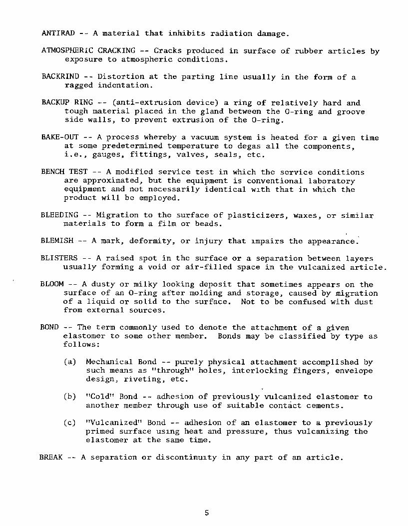
ANTIRAD -- A material that inhibits radiation damage.
ATMOSPHERIC CRACKING -- Cracks produced in surface of rubber articles byexposure to atmospheric conditions.
BACKRIND -- Distortion at the parting line usually in the form of aragged indentation.
BACKUP RING -- (anti-extrusion device) a ring of relatively hard andtough material placed in the gland between the 0-ring and grooveside walls, to prevent extrusion of the 0-ring.
BAKE-OUT -- A process whereby a vacuum system is heated for a given timeat some predetermined temperature to degas all the components,i.e., gauges, fittings, valves, seals, etc.
BENCH TEST -- A modified service test in which the service conditionsare approximated, but the equipment is conventional laboratoryequipment and not necessarily identical with that in which theproduct will be employed.
BLEEDING -- Migration to the surface of plasticizers, waxes, or similar
materials to form a film or beads.
BLEMISH -- A mark, deformity, or injury that impairs the appearance.
BLISTERS -- A raised spot in the surface or a separation between layersusually forming a void or air-filled space in the vulcanized article.
BLOOM -- A dusty or milky looking deposit that sometimes appears on thesurface of an O-ring after molding and storage, caused by migrationof a liquid or solid to the surface. Not to be confused with dustfrom external sources.
BOND -- The term commonly used to denote the attachment of a givenelastomer to some other member. Bonds may be classified by type asfollows:
(a) Mechanical Bond -- purely physical attachment accomplished bysuch means as "through" holes, interlocking fingers, envelopedesign, riveting, etc.
(b) "Cold" Bond -- adhesion of previously vulcanized elastomer toanother member through use of suitable contact cements.
(c) "Vulcanized" Bond -- adhesion of an elastomer to a previouslyprimed surface using heat and pressure, thus vulcanizing theelastomer at the same time.
BREAK -- A separation or discontinuity in any part of an article.
5

BREAKOUT -- Force to inaugurate sliding. Expressed in same terms asfriction. An excessive breakout value is taken as an indication ofthe development of adhesion.
BRITTLENESS -- Tendency to crack when deformed.
BUNA N -- Same as nitrile rubber.
BUNA S -- A general term for the copolymers of butadiene and styrene.Also known as SBR and GRS.
BUTT JOINT -- Joining two ends of a seal whereby the junction is perpen-dicular to the mold parting line.
BUTYL -- A copolymer of isobutylene and isoprene.
COEFFICIENT OF THERMAL EXPANSION -- Average expansion per degree over astated temperature range, expressed as a fraction of initial dimen-sion. May be linear or volumetric.
COLD FLEXIBILITY -- Flexibility following exposure to a predetermined
low temperature for a predetermined time.
COLD FLOW -- Continued deformation under stress.
COMPOUND -- A term applied to a mixture of polymers and other ingredients,to produce a usable rubber material.
COMPRESSION MODULUS - The ratio of the compressive stress to the resultingcompressive strain (the latter expressed as a fraction of theoriginal height or thickness in the direction of the force).Compression modulus may be either static or dynamic.
COMPRESSION SET -- The amount by which a rubber specimen fails to returnto original shape after release of compressive load.
CONDUCTIVE RUBBER -- A rubber capable of conducting electricity. Mostgenerally applied to rubber products used to conduct static elec-tricity.
CORROSION (PACKING) -- Corrosion of rigid member (usually metal) whereit contacts packing. The actual corroding agent is fluid mediumtrapped in the interface.
CORROSIVE (PACKING) -- A property of packing whereby it is assumed,often incorrectly, to promote corrosion of the rigid member by thetrapped fluid.
CRACKING -- A sharp break or fissure in the surface. Generally due toexcessive strain.
CREEP -- The progressive relaxation of a given rubber material while itis under stress. This relaxation eventually results in permanentdeformation or "set."
6

CROSS SECTION -- A seal as viewed if cut at right angles to the mold
parting line showing internal structure.
CURE -- See Vulcanization.
CURE DATE -- Date when 0-ring was molded, e.g., 2Q73 means the secondquarter of 1973.
CURING TEMPERATURE -- The temperature at which the rubber product isvulcanized.
CYLINDER -- Chamber in which piston, plunger, rain, rod, or shaft isdriven by or against the system fluid.
DIFFUSION -- The mixing of two or more substances (solids, liquids,gases, or combinations thereof) due to the random motion oftheir molecules. Gases diffuse more readily than liquids; similarly,liquids diffuse more readily than solids.
DUROMETER -- (a) An instrument for measuring the hardness of rubber.Measures the resistance to the penetration of an indenter pointinto the surface of rubber. (b) Numerical scale of rubber hardness.
DYNAMIC -- An application in which the seal is subject to movement ormoving parts contact the seal.
DYNAMIC SEAL - - A seal required to prevent leakage past parts that arein relative motion.
ELASTICITY - - The property of an article that tends to return it to itsoriginal shape after deformation.
ELASTOMER -- Any synthetic or natural material with resilience or memorysufficient to return to its original shape after major or minordistortion.
)ELEMENT -- The smallest part(s) that a seal or component can be dividedinto or the smallest procedure(s) that a process, such as installation,can be divided into.
ELONGATION -- Generally means "ultimate elongation" or percent increasein original length of a specimen before it breaks.
EVAPORATION -- The direct conversion from liquid state to vapor state ofa given fluid.
EXTRUSION -- Distortion or flow, under pressure, of portion of seal intoclearance between mating metal parts.
FILLER -- Chemically inert, finely divided material added to the elastomerto aid in processing, improve physical and mechanical properties (i.e.,improve abrasion resistance and strength), and control hardness.
7

FLASH -- Excess rubber left around rubber part after molding due tospace between mating mold surfaces; removed by trimming.
FLEX CRACKING -- A surface cracking induced by repeated bending orflexing.
FLEX RESISTANCE -- The relative ability of a rubber article to withstand
dynamic bending stresses.
FLOCK -- Fibrous filler sometimes used in rubber compounding.
FLOW CRACKS -- Surface imperfections due to improper flow and failure ofstock to knit or blend with itself during the molding operation.
FLUID -- A liquid or a gas.
FRICTION -- Resistance to motion due to the contact of surfaces.
FRICTION (BREAKOUT) -- Friction developed during initial or startingmotion.
FRICTION (RUNNING) -- Constant friction developed during operation of adynamic O-ring.
FUEL (AROMATIC) -- Fuel that contains benzene or aromatic hydrocarbons.Causes high swell of'rubber.
FUEL (NONAROMATIC) -- Fuel that is composed of straight chain hydro-carbons. Causes little swell of rubber.
GASKET -- A device used to retain fluids under pressure or seal outforeign matter. Normally refers to a static seal.
GLAND -- Cavity into which O-ring is installed. Includes the groove andmating surface of second part that together confine the O-ring.
GROOVING -- Putting the O-ring into the groove.
HARDNESS -- Resistance to a distorting force. Measured by the relativeresistance of the material to an indentor point of any one of anumber of standard hardness testing instruments.
HARDNESS SHORE A -- The rubber durometer hardness as measured on a Shore"A" gauge. Higher numbers indicate harder material. A 35 Shore "A"durometer reading is considered soft; a 90 is considered hard.
HERMETIC SEAL -- An airtight seal evidencing no leakage.
HOMOGENEOUS (a) General -- a material of uniform composition throughout.(b) In seals -- a rubber seal without fabric or metal reinforcement.
HYPALON -- DuPont trade name for chlorosulphonated polyethylene, anelastomer.
8

IMMEDIATE SET -- The deformation found by measurement immediately afterremoval of the load causing the deformation.
IMMERSION -- Placing an article into a fluid, generally so it is com-pletely covered.
IMPACT -- The single, instantaneous stroke or contact of a moving bodywith another, either moving or at rest, such as a large lump ofmaterial dropping on a conveyor belt.
LEAKAGE RATE -- The rate at which a fluid (either gas or liquid) passesa barrier. Total Leakage Rate includes the amounts that diffuse orpermeate through the material of the barrier as well as the amountthat escapes around it.
LOGY -- Sluggish, low snap or recovery of a material.
MEMORY -- Tendency of a material to return to original shape afterdeformation.
MIRROR FINISH -- A bright, polished surface.
MISMATCH -- Unsymmetrical seal caused by dissimilar cavities in matingmold sections.
MODULUS -- As a measure of stiffness for elastomers, the stress requiredfor a given elongation, such as 100% or 300%.
MODULUS OF ELASTICITY -- Ratio of stress to elastic strain--a constantfor metals but not for elastomers.
MOLD FINISH -- The uninterrupted surface produced by intimate contact ofrubber with the surface of the mold at vulcanization.
MOLD MARKS -- Indentations or ridges embossed into the skin of themolded product by irregularities in the mold cavity surface.Parting line flash is an example.
MOONEY SCORCH - The measurement of the rate at which a rubber compoundwill cure or set up by means of the Mooney Viscometer test instru-ment.
MOONEY VISCOSITY -- The measurement of the plasticity or viscosity of anuncompounded or compounded, unvulcanized, elastomeric seal materialby means of the Mooney Shearing Disk Viscometer.
NITRILE (BUNA-N) -- The most commonly used elastomer for O-rings becauseof its resistance to petroleum fluids, good physical properties, anduseful temperature range.
NOMINAL DIMENSION -- Nearest fractional equivalent to actual decimaldimension.
9

OCCLUSION -- (a) The mechanical process by which vapors, gases, liquids,or solids are entrapped within the folds of a given substanceduring working or solidification. (b) The materials so trapped.
OFF-REGISTER -- Misalignment of mold halves causing out-of-round O-ringcross section.
OIL-RESISTANT -- Ability of a vulcanized rubber to resist the swellingand deteriorating effects of various type oils.
OIL SWELL - The change in volume of a rubber article due to absorptionof oil or other fluid.
O-RING -- A torus; a circle of material with round cross section whicheffects a seal through squeeze and pressure.
O-RING SEAL -- The combination of a gland and an O-ring providing afluid-tight closure. (Some designs may permit momentary or minimumleakage.)
Moving (dynamic) -- O-ring seal in which there is relative motionbetween some gland parts and the O-ring--oscillating, reciprocatingor rotary motion.
Nonmoving (static) -- O-ring seal in which there is no relativemotion between any part of the gland and the O-ring (distortionfrom fluid pressure or swell from fluid immersion is excluded).
OPTIMUM CURE -- State of vulcanization at which the most desirable com-bination of properties is attained.
OUTGASSING -- A vacuum phenomenon wherein a substance spontaneously re-leases volatile constituents in the form of vapors or gases. Inrubber compounds, these constituents may include water vapor,plasticizers, air, inhibitors, etc.
OVERCURE -- A degree of cure greater than the optimum, causing some desir-able properties to be degraded.
OXIDATION -- The reaction of oxygen on a compound usually detected by achange in the appearance or feel of the surface, or by a change inphysical properties, or both.
OZONE RESISTANCE - Ability to withstand the deteriorating effect ofozone (which generally causes cracking).
PACKING -- A flexible device used to retain fluids under pressure orseal out foreign matter. Normally refers to a dynamic seal.
PARTING LINE FLASH -- Residual rubber that is squeezed out between thedies during molding.
PERMANENT SET - The deformation remaining after a specimen has beenstressed in tension for a definite period and released for adefinite period.
10

PERMEABILITY -- The rate at which a liquid or gas under pressure passesthrough a solid material by diffusion and solution. In rubber ter-minology, it is the rate of gas flow expressed in atmospheric cubiccentimeters per second through an elastomeric material 1 centimetersquare and I centimeter thick (atm cc/cm2 /cm/sec).
PIT OR POCK MARK -- A circular depression, usually small.
PLASTICIZER -- A substance, usually a heavy liquid, added to an elastomerto decrease stiffness, improve low temperature properties, andimprove processing.
PLASTOMETER -- An instrument for measuring the plasticity of raw or un-vulcanized compounded rubber.
POLYMER -- A material formed by the joining together of many (poly) indi-vidual units (mer) of one or more monomers; synonymous with elastomer.
POROSITY -- Quality or state of being porous.
POST CURE -- The second step in the vulcanization process for the moreexotic elastomers. Provides stabilization of parts and drives offdecomposition products resulting from the vulcanization process.
RADIATION - An emission of varying energy content from a disturbed atomundergoing internal change. There are two broad classifications ortypes:
(a) Corpuscular, comprising streams of particles either neutral orcharged, e.g., protons, electrons, neutrons.
(b) Electromagnetic, comprising wave-like emissions such as ultra-violet radiation, x-rays, and gamma rays.
RADIATION DAMAGE -- A measure of the loss in certain physical and mechan-ical properties of organic substances such as elastomers, dueprincipally to ionization of the long chain molecule. It is be-lieved that this ionization process (i.e., electron loss) resultsin redundant cross-linking and possible scission of the molecule.This effect is cumulative.
REINFORCING AGENT -- Material dispersed in an elastomer to improvecompression, shear, or other stress properties.
RELATIVE HUMIDITY -- The ratio of the quantity of water vapor actuallypresent in the atmosphere to the greatest amount possible at thegiven temperature.
RESILIENT -- Requires much energy to deform elastically.
11

ROUGHNESS AVERAGE -- Arithmetic average of surface irregularities,abbreviated Ra; also called AA and CLA.
ROUGH TRIM -- Removal of superfluous material by pulling or picking.Usually the removal of a small portion of the flash or sprue whichremains attached to the product.
RUBBER -- Same as elastomer.
RUBBER, NATURAL - Raw or crude rubber obtained from vegetable sources.
RUBBER, SYNTHETIC -- Manufactured or man-made elastomers.
RUNOUT (SHAFT) - Same as gyration; when expressed in inches alone oraccompanied by abbreviation "TIR" (total indicator reading), itrefers to twice the radial distance between shaft axis and axisof rotation.
SCORCHING -- Premature curing or setting up of raw compound duringprocessing.
SEAL -- Any device used to prevent the passage of a fluid (gas or liquid).
SEATING -- Squeezing the O-ring between the sealing surfaces by closingthe gland.
SERVICE -- Operating conditions to be met.
SHELF-AGING -- The change in a material's properties that occurs in
storage with time.
SHORE A HARDNESS -- See Hardness and Durometer.
SHRINKAGE -- Decreased volume of seal, usually caused by extraction ofsoluble constituents by fluids followed by air drying.
SILICONE RUBBER -- Elastomer that retains good properties through extrawide temperature range.
SIZE, ACTUAL -- Actual dimensions of the O-ring or other seal, includingtolerance limits.
SIZE, NOMINAL -- Approximate size of a part in fractional dimensions.May also indicate the actual size of the groove into which a nominalsize seal fits.
SIZE NUMBER -- Number assigned to indicate inside and cross sectiondiameters of an O-ring. Sizes established in SAE standard AS568have been adopted by the military and industry.
SORPTION -- The term used to denote the combination of absorption andadsorption processes in the same substance.
1I

SPECIFIC GRAVITY -- The ratio of the weight of a given substance to theweight of an equal volume of water at a specified temperature.
SPRUE MARKS -- Marks left on the surface of a rubber part, usually ele-vated, after removal of the sprue or cured compound in the gatethrough which the compound is injected or transfer molded.
SQUEEZE -- Cross section diametral compression of O-ring between surfaceof the groove bottom and surface of other mating metal part in thegland assembly.
STATIC SEAL -- Part designed to seal between parts having no relativemotion. See Gasket.
STEP -- One or a group of elements in a procedure such as grooving.
STRAIN -- Deformation per unit original length.
STRESS -- Force per unit of original cross section area.
SUBLIMATION -- The direct conversion of a substance from solid state tovapor state without passing through a transitory liquid state. Thevapor, upon recondensing, reforms into the solid state with nointervening liquid phase.
SUN CHECKING -- Surface cracks, checks or crazing caused by exposure todirect or indirect sunlight.
SWELL -- Increased volume of a specimen caused by immersion in a fluid(usually a liquid).
TEAR RESISTANCE -- Resistance to growth of a cut or nick when tension isapplied to the cut specimen. Commonly expressed as pounds per inchthickness.
TEMPERATURE RANGE -- Maximum and minimum temperature limits within whicha seal compound will function in a given application.
TENSILE STRENGTH -- Stress required to cause the rupture of a specimenof a rubber material.
THERMAL EXPANSION -- Expansion caused by increase in temperature. Maybe linear or volumetric.
TORQUE -- The turning force of a shaft.
TORSIONAL STRENGTH -- Ability of rubber to withstand twisting.
TRAPPED AIR -- Air that is trapped in a connector or seal.
TRIM -- The process involving removal of mold flash.
TRIM CUT -- Damage to mold skin or finish by too close trimming.
13

UNDERCURE -- Degree of cure less than optimum. May be evidenced by
tackiness, loginess, or inferior physical properties.
ULTIMATE ELONGATION -- See Elongation.
VACUUM -- The term denoting a given space that is occupied by a gas atless than atmospheric pressure.
VAPOR -- A gas at a temperature below the critical temperature so that itcan be liquefied by compression without lowering the tempera-ture. Fog and gas streams from atomizers are common examples.
VAPOR PRESSURE -- The maximum pressure exerted by a liquid (or solid)heated to a given temperature in a closed container.
VISCOSITY -- The property of fluids and plastic solids by which theyresist an instantaneous change of shape, i.e., resistance to flow.
VOID -- The absence of material or an area devoid of materials where notintended.
VOLATILIZATION -- The transition of either a liquid or a solid directlyinto the vapor state. In the case of a liquid, this transition iscalled evaporation, whereas in the case of a solid, it is termedsublimation.
VOLUME CHANGE -- A change in the volume of a seal as a result of immersionin a fluid, expressed as a percentage of the original volume.
VOLUME SWELL -- Increase in physical size caused by the swelling actionof a liquid.
VULCANIZATION - A thermo-setting reaction involving the use of heat andpressure, resulting in greatly increased strength and elasticity ofrubber-like materials.
VULCANIZING AGENT -- A material that produces vulcanization of anelastomer.
WIDTH -- Seal cross section or thickness.
WIPER RING -- A ring employed to remove excess fluid, mud, etc., from areciprocating member before it reaches the packings.
14
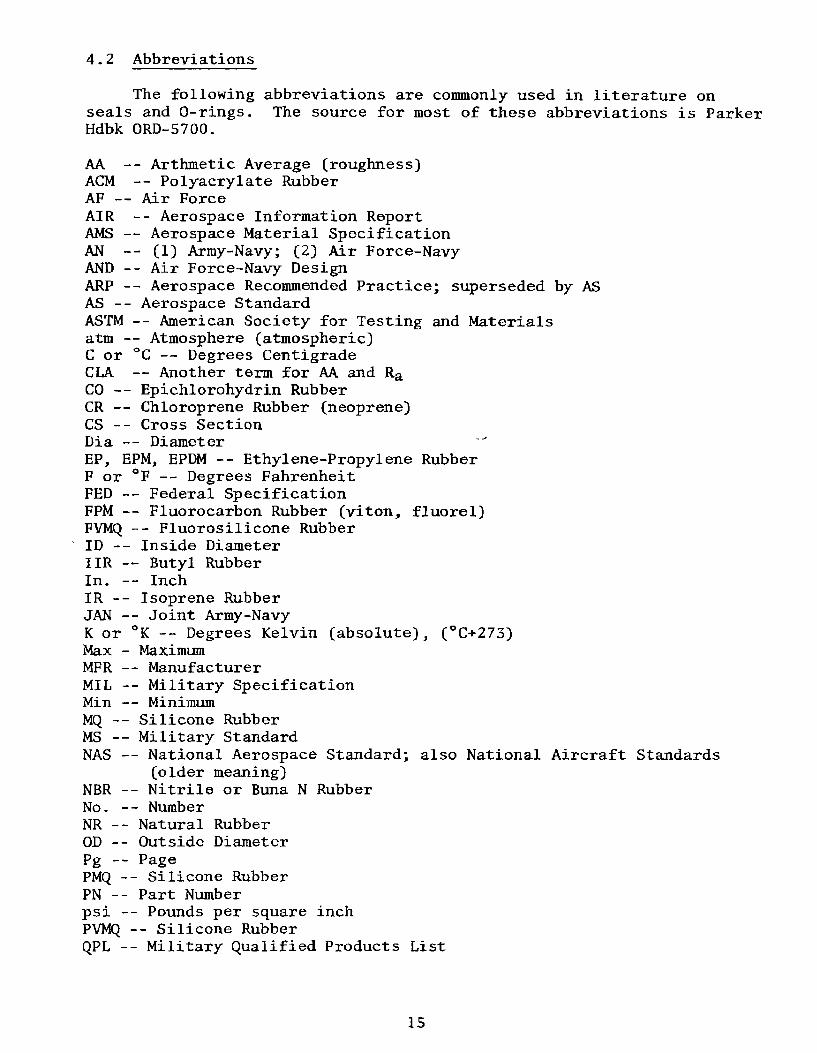
4.2 Abbreviations
The following abbreviations are commonly used in literature onseals and O-rings. The source for most of these abbreviations is ParkerHdbk ORD-5700.
AA -- Arthmetic Average (roughness)ACM -- Polyacrylate RubberAF -- Air ForceAIR -- Aerospace Information ReportAMS -- Aerospace Material SpecificationAN -- (1) Army-Navy; (2) Air Force-NavyAND -- Air Force-Navy DesignARP -- Aerospace Recommended Practice; superseded by ASAS -- Aerospace StandardASTM -- American Society for Testing and Materialsatm -- Atmosphere (atmospheric)C or 0C -- Degrees CentigradeCLA -- Another term for AA and RaCO -- Epichlorohydrin RubberCR -- Chloroprene Rubber (neoprene)CS -- Cross SectionDia -- DiameterEP, EPM, EPDM -- Ethylene-Propylene RubberF or 'F -- Degrees FahrenheitFED -- Federal SpecificationFPM -- Fluorocarbon Rubber (viton, fluorel)FVMQ -- Fluorosilicone RubberID -- Inside DiameterIIR -- Butyl Rubber
In. -- InchIR -- Isoprene RubberJAN -- Joint Army-NavyK or 0K -- Degrees Kelvin (absolute), ( 0 C+273)Max - MaximumMFR -- ManufacturerMIL -- Military SpecificationMin -- MinimumMQ -- Silicone RubberMS -- Military StandardNAS -- National Aerospace Standard; also National Aircraft Standards
(older meaning)NBR -- Nitrile or Buna N RubberNo. -- NumberNR -- Natural RubberOD -- Outside DiameterPg -- PagePMQ -- Silicone RubberPN -- Part Numberpsi -- Pounds per square inchPVMQ -- Silicone RubberQPL -- Military Qualified Products List
15

Ra -- Arithmetic Average RoughnessRad -- Radiusrms -- Root-mean-square; the square root of the mean of the sum of the
squares of the heights of surface irregularitiesSAE -- Society of Automotive Engineers, Inc.Spec -- SpecificationTemp. -- TemperatureVMQ -- Silicone RubberW -- Width (seal cross section)
16

5. O-RING SEALS, GENERAL
5.1 0-ring Definition. An 0-ring is a rubber torus, or doughnut-shaped ring, with a circular cross section as shown in Figure 5.1.Q Figure 5. 1
0-ring shape.0
5.2 0-ring Dimensions. An 0-ring is defined dimensionally by itscross-section diameter (thickness) W and inside diameter (ID) as shownin Figure 5.2. 0-rings are commonly made in five standard cross sec-tions with nominal inside diameters (like the diameter of the doughnuthole) ranging from 1/32 to 26 in. (0.79 to 660 mm). Refer to AN6227.
CROSS
00 iFigure 5.2- - -0,003 in
(0.08Mm) 0-ring dimensions.Mtx --.FLASH FROM
- MOLDING
LA •- •- CROSS r7//SECTION V'77A
INSIDE DiAM _ I_ jF0 _~ .~0.005 in
(0.13 m m)
5.3 How 0-rings Seal. When properly installed in its gland, the cir-cular cross section of the 0-ring is squeezed between the top of thegland and the bottom of the gland as shown in the top sketch inFigure 5.3. The gland is the cavity that contains the 0-ring. Aspressure is applied, the 0-ring slides to the low pressure side of thegland and prevents the fluid (seawater or gas) from crossing the gland(bottom sketches in Figure 5.3). Sealing takes place because the pres-sure of the fluid and the initial installation squeeze force the 0-ringagainst the gland walls and into the gap so hard that no liquid or gasmolecules can pass. The critical sealing surfaces are shown inFigure 5.4. The critical surface is really an interface where threethings (gland metal surface, rubber 0-ring, and 0-ring lubricant) aretightly compressed. The pressure produces the seal. The lubricant isapplied to the 0-ring and the gland surfaces for three main reasons--toreduce friction (i.e., to help the rubber 0-ring slide during instal-lation, form to the gland surface, and prevent adhesion); to keep waterfrom the sealing surfaces; and to fill all voids under the rubber.
17

SQUEEZE
a GAP
- GROOVE
NO PRESSURE
GLAND CROSS SECTION
Figure 5.3 *PRESSURE
Sealing action.
PRESSURE APPLIED
PRESSURE+444
PRESSURE REVERSED
CRITICAL SEALING SURFACE
LOW 66*LOW ' ' IIPRESSUREPRESSURE LUBRICANT PR E Figre 5
Critical sealing surfaces* * *and sealing mechanism.
*PRESSURE' Sealing is produced by* • *'*the pressure between the
0-ring and gland surfaces.
;LUBRI CANT/
CRITICAL SEALING SURFACE
18

The 0-ring rubber deforms to match nearly all of the fine machine-tootgrooves (which are so small they are barely visible to the naked eye)and the lubricant fills all the rest of the grooves as shown inFigure S.S. The reliability and success of the seal depend on thiscritical sealing surface, or interface, that runs all around the 0-ring.If anything goes wrong anywhere on that interface, the seal will leak.Dirt, hair, fibers, scratches, or cuts cause LEAKS as shown in Figure 5.6.The water can wick through a fiber or dirt and break the seal. Thussurfaces must be clean and free of scratches or cuts.
-RSSR
PRESSURE
TOWLRGROOVE
//\/ /
TOLGROOVESWL -N
>META TRUBERSGROOVE WALL O-RING
LUBRICANT LUBRICANT
FIBER, DIR
OR HAIR ##WATER
Figure 5.5 Enlarged view of critical Figure 5.6 How water can leak pasgland sealing surface, or interface, the 0-ring because of contaminatio.where groove wall, rubber 0-ring, and by fibers, dirt, or hair.lubricant meet and are tightly com-pressed together to produce a reliableseal.
19

5.4 Types of O-ring Seals. O-ring seals are normally either dynamic(i.e., they often slide, rotate, or vibrate during use) or static (sta-tionary). In this Handbook, only static O-ring seal designs are con-sidered. Face seals (sometimes called flange seals) squeeze the O-ringinto a groove with a flange or face plate as shown in Figure 5.7. Capand plug seals are alike except for the gender of the glands as shown inFigure S.8. The cap seal has the groove in the female part whereas theplug seal has the groove in the male part. The cap and plug are reallyforms of static piston seals because the plug is like a cylinder. Thecommon static piston-type seals are shown in Figure 5.8. The dynamicpiston-type (sometimes called rod-type) seals are shown in Figure 5.9.The crush-type seal is shown in Figure 5.10. Refer to MIL-G-5514F.
CAP SEAL PLUG SEAL
CAP END PI ECE' ~ PLUG END PIECE
If-' MALEFEMALE L L.GLAND ---
FLANGE SEAL
FACE SEAL
Figure 5. 7. Static-type seals (cap, plug, flange, and face). Notethat gap in flange and face seals can be essentiallyzero, permitting sealing of very high pressures.

r PISTON
PISTON (ROD) SEAL CYLINDER
0-RING Figure 5. 8MALE GLAND
PISTON Common static piston-type seals.
CYLINDER
PISTON SEAL O-RING
"*- FEMALE GLAND
ROD
Figure 5.9
Dynamic piston-type (rod)seats (shown for compari- PISTON (ROD) SEAL
son). FEMALE GLAND
•') PISTON
-. PISTON SEALMALE GLAND
- CRUSH SEAL Figure 5.10
Crush-type seal.
k\ O-RING VOLUME IS90-95 % GLAND VOLUME
21

5.5 Gland Definitions. The common parts of the static 0-ring sealglands are identified in Figure S.11.
5.6 Extrusion and Backup Rings. When the outside or inside pressurebecomes very high or the clearance gap is necessarily large, the 0-ringmay be extruded (pushed too far into the gap). To prevent extrusion, abackup ring is installed between the low pressure side of the gland andthe 0-ring as shown in Figure 5.12. When high pressure may occur oneither side of the 0-ring, double backup rings are installed as shown inFigure 5.12. Backup rings are commonly made of hard rubber, plastic, orleather.
NO SHARP7 RADIUSEDGES /-
GLAND GROOVEJDEPTH I DEPTH THESE SURFACES
/ REQUIRE SPECIAL
G FINISHCLEARANCE
GROOVE DETAIL FEMALE GLANDO-R-\ GROOVE --- OSLEEVE OD
HFEMALE GLAND
GGROOVE I D
'N LFEMALE GLANDRHOUSING BORE
CYLINDER ODMALE GLAND ROD GLAND-' -" G
BORE ID OPDSTON DOD
CLEARANCE CLEARANCEROD BORE I D-
-PISTON GROOVE ID ROD GLAND
CYLINDER BORE ID GROOVE OD
Figure 5._1. Gland definitions (conmnon).
EXTRUSION 44,, PRESSURE
~JTCLE RANCESINGLENO BACKP ARAN BACKUPRING UVGjAP RiNG
**PRESSURE PRESSURE4,
DOUB3LE DOUBLEBACKUP BACKUPRINGS RINGS
Figure 5.12 TypicaZ backup rings.
22

6. O-RING SEAL PROBLEMS
6.1 General. O-ring seals leak or create other problems because atleast one of the following has occurred before the end of expectedservice:
O-ring left out (see Figure 6.1)Bad installation of good O-ring in good gland (see Figures 6.2-6.5)Good installation, good O-ring, bad gland (see Figures 6.6-6.8 and
6.11)Bad or wrong O-ring used in good gland (see Figures 6.9 and 6.10)Good installation, good O-ring, good gland, wrong environment (too
corrosive) or wrong gland material (see Figure 6.11)
6.2 O-ring Problems. O-ring problems and the responsible person orcause are as follows:
O-ring left out (see Figure 6.1) -- installerO-ring cut or cracked (see Figures 6.4, 6.5, and 6.10) -- storage,
installer, exposureDirty O-ring or gland (see Figures 6.2 and 6.3) -- installer,
storageWrong O-ring (see Figure 6.9) -- installer, designer, or supplier.
The installer should not install an O-ring with any of the problemslisted above. Even though the installer may not have caused the prob-lem, he is responsible for seeing that damaged O-rings do not getinstalled.
6.3 Gland Problems. Gland problems and the responsible person orcauses are as follows:
O-ring extrusion -- excessive clearance; designer or machinist(see Figure 6.8)
-- shallow groove; designer or machinist(see Figure 6.8)
O-ring leak -- insufficient squeeze; designer, machinist,or installer (see Figures 6.7 and 6.9)
-- cut O-ring; designer (chamfer, alignment) or installer(see Figures 6.4 and 6.5)
-- scratch in gland; machinist or installer (seeFigure 6.6)
-- improper lubricant distribution*; installer (seeFigures 6.4 and 6.11)
-- corrosion path; installer, designer, machinist, orheat treater (see Figure 6.11)
-- dirty or contaminated; installer (seeFigures 6.2 and 6.3)
Gland interference -- machinist, designer
Gland burrs -- machinist
*Refer to Section 8.2.20 for description of proper lubrication.
23
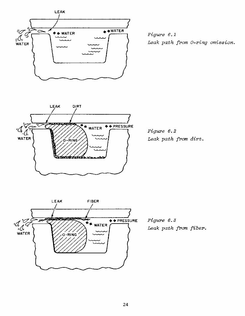
LEAK
Irk / IS
(& +WAT E 4,,41WATER Figure 6.1
WATER Leak path from O-ring omission.
LEAK DIRT
WAE *+PRESSUREpahfo
Figure 6.2
WATER Leak path from dirt.
LEAK FIBER/ /
Yy O1,*PRESSURE Figure 6.3
-WATER Leak path from fiber.WATER
24

CUT OFFLEAK PIECE/
i21 7* +PRESSURE Fgure 6.4
WATERFiue64WATER Leak path from cutting on
installation (due to lackof lubricant or improperchamfer).
Figure 6. 5
Double 0-ring seal ofmain signal cable endof junction chamber,showing cut piece of
" 0-ring backup gland
deposited in the first0-ring groove. (Plug-type seal, male gland.)Cause: misalignmentduring in ta l lation.
METAL
LEAK SCRATCH/ /
WATER + + PRESSURE-
WATER ORNFigure 6. 6
Leak path from metal scratch.
25

O-RING SHAPEAFTER BEFORE PRESSURE
LEAK PRESSURE (LOW SQUEEZE)
WAT ER •/ \•Leak path from low squeeze.
LEAK
•;" ;•(::ii:/C;•41,PRESSU/RE Fibure 6.8
Leak path from extrusion//AER• (gfap tolerance too high
S~or groove too shallow).
.0-RING
EXTRUDED{(PUSHED-OUT)O -RING
LEAK
•, "d~C;:. ";:-, *1 WATER • • PRESSUIRE
,WATERSFigure 6.9
• • Leak path from wrong size O-ring.
26

LEAK CUT OR CRACK/ /
'-, - .9 4 *#PRESSURE
WAATERWATER
Figure 6. 10
Leak path from cut (or cracked)0-ring.
LEAK CORROSION
CC>>- /PRESSURE"" d [ • ///////•WATER f-
Figure 6. 11
WATER -Leak path from corrosion (dueto lack of lubricant and corro-sive environment).
27
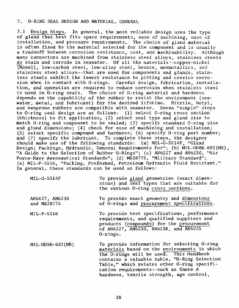
7. O-RING SEAL DESIGN AND MATERIAL, GENERAL
7.1 Design Steps. In general, the most reliable design uses the typeof gland that best fits space requirements, ease of machining, ease ofinstallation, and pressure requirements. The choice of gland materialis often fixed by the material selected for the component and is usuallya tradeoff between corrosion resistance, cost, and machinability. Althoughmany connectors are machined from stainless steel alloys, stainless steelsdo stain and corrode in seawater. Of all the materials--copper-nickel(Monel), low-carbon steel, low-alloy steel, bronze, nonmetallics, andstainless steel alloys--that are used for components and glands, stain-less steels exhibit the lowest resistance to pitting and crevice corro-sion when in contact with O-rings. Careful design, fabrication, installa-tion, and operation are required to reduce corrosion when stainless steelis used in O-ring seals. The choice of O-ring material and hardnessdepends on the capability of the rubber to resist the environment (sea-water, metal, and lubricant) for the desired lifetime. Nitrile, butyl,and neoprene rubbers are compatible with seawater. Seven "simple" stepsto O-ring seal design are as follows: (1) select O-ring cross section(thickness) to fit application; (2) select seal type and gland size tomatch O-ring and component to be sealed; (3) specify standard 0-ring sizeand gland dimensions; (4) check for ease of machining and installation;(5) select specific compound and hardness; (6) specify O-ring part number;and (7) specify the lubricant. To complete these steps, the designershould make use of the following standards: (a) MIL-G-S514F, "GlandDesign; Packings, Hydraulic, General Requirements For"; (b) MIL-HDBK-692(MR),"A Guide to the Selection of Rubber O-Rings"; (c) AN6227 and AN6230, "AirForce-Navy Aeronautical Standards"; (d) MS28775, "Military Standard";(e) MIL-P-5516, "Packing, Preformed, Petroleum Hydraulic Fluid Resistant."In general, these standards can be used as follows:
MIL-G-5514F To provide gland geometries (exact dimen-sions) and seal types that are suitable forthe various O-ring cross sections.
AN6627, AN6230 To provide exact geometry and dimensionsand MS28775 of O-rings and procurement specifications.
MIL-P-5516 To provide test specifications, performancerequirements, and qualified suppliers andproducts (compounds) for the procurementof AN6227, AN6230, AN6238, and AN6225O-rings.
MIL-HDBK-692(MR) To provide information for selecting O-ringmaterials based on the environments in whichthe O-rings will be used. This Handbookcontains a valuable table, "0-Ring SelectionTable," which relates other O-ring specifi-cation requirements--such as Shore Ahardness, tensile strength, age control,
28
packaging, and marking--with dimensionspecifications, material specifications,and elastomers commonly used in variousenvironments.
Similar information is available in commercial O-ring handbooks such asParker Handbook ORD-5700 and National O-Ring Design Guide OR-15R. Thedimensions used in commercial gland designs can differ slightly fromthe gland dimensions specified in Military Standards.
7.1.1 Select the O-ring Cross Section. O-ring cross sections come inseveral standard sizes: 0.040 in. (1.02 mm), 0.050 in. (1.27 mm),0.060 in. (1.52 mm), 0.070f1/14 in. (1.78 mm); 0.103=1/10 in. (2.62 mm);0.139=1/8 in. (3.53 mm); 0.210=7/32 in. (5.33 mm); 0.275=9/32 in. (6.99 mm).Metric O-rings in even millimeter widths are also available frommanufacturers in the United States. The 0-ring crosssection (W) and inside diameter (ID) that fit the component will guidethe selection.* The range of ID's is fixed by the component's diameter.Select the largest cross section (thickest or fattest) that will fit inthe available space. Large (fat) O-rings are more resistant to damageby abrasion, rolling, or twisting during installation. They are alsomore resistant to damage due to stretch and squeeze. It is especiallynoted that fat O-rings produce a larger critical sealing surface andtherefore are more resistant to leaks due to corrosion, dirt, scratches,etc. Refer to MIL-G-5514F, AN6227, AN6230, and MS28775.
7.1.2 Select the Seal Type and Gland Size. Select the seal type thatmakes the component easiest to use, machine, and assemble. Select thegland size that matches the seal type and the 0-ring cross section.
7.1.3 Specify the Standard O-ring Size and the Gland Dimensions.Example: AN6227-32 = an O-ring with a width of 0.210 in. (5.33 mm) andand ID of 1.975 in. (50.17 mm).
7.1.4 Select the Elastomer and Specify the Compound. The common elas-tomers (about 15 total) include nitrile, ethylene-propylene, neoprene,fluorocarbon, and silicone. If an AN or MS O-ring is selected, thematerial and hardness as well as the dimensions are fixed because AN andMS drawings state that the O-ring must meet certain material specifi-cations. AN6227, for example, requires that the material meet MIL-P-5516Class B specifications. Although MIL-P-5516 does not require nitrile,it will probably be the material supplied because, at this time, it isthe only compound that has been qualified by the manufacturers andapproved by the military as meeting the tests specified in MIL-P-5516.How, then, can an engineer specify an O-ring with AN or MS dimensions butmade out of some other material such as a silicone compound? One non-standard but successful method is to contact the supplier (or use hiscatalogs) and specify the supplier's compound number for the desiredmaterial on the drawing and on the purchase order next to the O-ring ANnumber. The second, and more desirable, method is to translate the ANO-ring number into its corresponding AS O-ring size number. For example,
*OD = 2W+ ID may also guide the selection.

AN6227B-25 dimensions correspond exactly to AS568-220 dimensions Creferto Section 15.1, AN6227), but whereas the AN drawing specifies a material,the AS drawing does not. The O-ring material must be specified by theengineer as meeting some material specification such as MIL-G-21569Class II, which is met by certain silicone durometer 70 compounds [refer
-to MIL-HDBK-692(MR)]. If nonmilitary specifications are acceptable (forspecial cases only), suppliers' catalogs can be used to call out on thedrawing and purchase order an O-ring made of a supplier's specificpolymer, and even with a supplier's O-ring dimensions. The supplier'sO-ring dimensions must be checked to be sure they match the desireddimensions.
7.1.5 Recommended Component and Seal Design Specifications. Thefollowing recommendations for component and seal design were developedfrom experience and were composed by members of the Undersea Cable andConnector Committee of the Marine Technology Society. (See Reference 21in Section 15.2). The recommendations have been modified slightly forthis Handbook.
1. The physical properties of the O-ring material should be suchas to maintain pressure proof integrity in seawater and fresh-water environments for a period of at least five years.
2. The O-ring should be capable of withstanding service tempera-tures from -6S°F to +165 0 F (-540 C to +74 0 C).
3. The O-ring should be capable of passing thermal shock testsof -65'F to +28 0 F (-54 0 C to -2 0 C) and +165 0 F to +28 0 F (+74 0 Cto -2 0 C). These are the conditions that are encountered inarctic and tropical climates.
4. The seal design must be such that the plug and receptacle canbe mated and unmated many times without damaging or otherwiseaffecting the O-ring or seal surfaces. A recommended durabilitytest is 100 cycles (one cycle is a mating and unmating).
5. The design of the plug and receptacle should be such that itdoes not require an O-ring that is not readily available.Standard O-ring shapes, sizes, and materials are preferable.
6. The O-rings chosen for the application should be inexpensive.
7. The seal design must be capable of withstanding at least 2000hydrostatic pressure cycles to a pressure equivalent to thedepth for which the seal is designed. If the characteristicsof the O-ring material are not fully known, it may be desirableto superimpose a temperature cycle during the hydrostaticpressure tests.
8. The O-ring design should be capable of withstanding a statichydrostatic pressure test to 1.5 times the operating designdepth for a period of 16 hours minimum.
30

9. The seal design should be such that the gasket is not dislodgedduring the mating and unmating cycles, as this could result inO-ring damage or loss.
10. Each O-ring should be individually packaged and properly iden-tified as to material, size, shape, and shelf life.
11. The connector seal should be designed so that the O-ring isreadily accessible for installation or removal. O-ring in-stallation and removal tools should be designed to precludedamage to the O-ring or the O-ring seal surfaces.
12. The connector seal design should afford the maximum possibledamage protection to the surfaces being sealed.
13. If the effectiveness of the seal design selected depends onthe application of minimum torque values, the minimum andmaximum allowable torque values should be specified.
14. The seal design and the O-ring should be such as to require aminimum of installation and removal instruction.
15. Where practical in the connector design, the use of doubleO-rings in separate glands (primary and secondary) is recom-mended. Each O-ring should be capable of maintaining a fullyeffective seal independently in the event of inadvertentomission of, or damage to, one of the O-rings.
16. The O-ring material should not deteriorate in the presence ofhydraulic lubricating or compensating oils.
17. The connector seal design should be capable of withstandingthe same shock and vibration as the unit to which it isattached.
18. The connector seal design should provide corrosion resistancein seawater and freshwater environments and should not promotecorrosion in the adjacent seal areas.
19. The O-ring material should be fungus resistant.
7.1.6 Select and Specify Lubricant. Refer to Section 13 of this Hand-book for specific data on, and descriptions of, the various O-ring lubri-cants. Petrolatum (petroleum base grease), MIL-G-4343 or DC 55 (siliconebase grease), and Parker O-Lube (barium base grease) are among the 12lubricants that are commonly used on O-rings. The deterioration of thelubricant with time in the seawater/gland environment and the lubricant'scompatibility with the environment (i.e., whether it will produce unde-sirable swelling or shrinking of the O-ring) must be considered.
31

8. INSTALLATION
8.1 Arrangement. This section describes a step method of installing0-rings in new or used components for marine and other static pressureapplications. First, an abbrevition of the step method is given, andthen detailed descriptions and explanations.
8.2 Scope. Installation as used in this Handbook encompasses the stepsor processes involved from obtaining the 0-rings and component partsfrom stores or the shop to releasing the assembled component for service.Installation includes withdrawing, accounting for, inspecting, checking,testing, lubricating, grooving (putting the 0-ring in the groove), seating,and testing. Installation is complete when tests of 0-ring seating giveno evidence of improper seating, and threaded or locking parts aresecure but not necessarily tightened. The following steps for the in-stallation should be followed unless other requirements are given inthe engineering drawings.
8.2.1 Abbreviated Step Method of 0-ring Installation
(a) Prepare for the installation by laying out the component partson a clean, lint free surface.
(b) From the configuration and position of each part, determine thesequence of assembly to prevent damage to the 0-ring or gland.
(c) Compare the part numbers with the drawings to ensure that theproper parts are being assembled.
(d) Check gland dimensions that set the squeeze and clearance gapagainst engineering drawings. (Tools: inside and outsidecalipers and a dial-indicating vernier caliper with 0.001 in.(0.025 mm) divisions.)
(e) Inspect gland sealing surfaces for cleanliness, proper finish,and absence of defects. Surfaces and edges must be free ofall contaminants, dirt, nicks, scratches, gouges, marks, andburrs. Some minor burrs can be removed by "touching" them with400 grit emery paper. Do not install 0-rings on componentsthat are not free of burrs or other imperfections.
(f) Clean sealing surfaces and all surfaces that the O-ring maycontact. (Only proper solvents can be used; the propersolvent depends on the base polymer. Refer to 8.2.12.)
(g) Protect all sealing surfaces from contamination and damage.
(h) Determine which 0-ring to install from the engineering drawings.
Example: AN6227B-25
32

(i) Withdraw the O-rings from stock just before (a few hours ordays) assembly.
(j) Cross check the O-ring identification on the package withthe drawings or specifications.
(k) Do not withdraw 0-rings in damaged packages or with a cure dateolder than 20 calendar quarters (5 years). Refer to Section 12.3.
(1) Maintain accountability for each O-ring. Each installer shouldkeep a record of the O-rings in his possession and record anychange in disposition (withdrawn, rejected, lost, discarded,or installed) and the date.
(m) Do not remove the O-ring from the package until ready to lubri-cate it for installation.
(n) Handle carefully to protect the O-rings from damage by finger-nails and tools, and from contamination by chemicals, dirt, andchips.
(o) Check the O-ring dimensions (W and OD) if on visual inspectionor during installation the O-ring size appears to be improper.
(p) Carefully inspect the O-ring visually for cracks, nicks, dents,or flat spots. Refer to Section 8.2.14, MIL-STD-177, andMIL-STD-413. No defects are allowable.
(q) Prepare for grooving by masking sharp edges (not groove edges)such as threads and holes on the component. Ensure that cham-fers are 100 to 20'.
(r) Determine the proper O-ring lubricant. If not specified on theengineering drawing, consult with the engineering department,which should select the lubricant from those listed in thisHandbook or from manufacturer's information. See Section 13,Lubricants.
(s) Lubricate with a thin, continuous film the O-ring and all partsurfaces and tools that will contact the O-ring during grooving.If service conditions are corrosive to sealing surfaces andassembly conditions permit, put sufficient lubrication in theO-ring groove that the groove will be full after the O-ring isin the groove. Refer to Section 8.2.20.
(t) Where possible, don't stretch or twist an O-ring. PreferablyO-rings will not be stretched at any time more than 50% ofthe initial ID. For example, an O-ring with an ID of 1.00 in.(25.4 mm) should not be stretched over a cylinder greater than1.50 in. (38.1 mm) in diameter.
33

(u) Groove the 0-ring with the least amount of twisting, stretch-ing, and rotation. Push the 0-ring down to the bottom ofthe groove and toward the back of the groove all around itsentire circumference. The back of the groove is the side thatthe 0-ring will be pushed against during assembly of thegland. The back is not necessarily the side that the 0-ringwill push against during service. The 0-ring may fill thegroove in some designs. (See Figure 8.1.)
SEATINGDIRECTION4, , 4, 1
MATINGES• SURFACE
•O-RING
BOTROOM OO
GROOVE
SBOTTOM OF
GROOVE
Figure 8.1. 0-ring against back and bottom of groove.
(v) Remove all twists. The parting line, if visible, on the0-ring can be used to straighten the 0-ring. (See Figure 8.2.)
i //
Figure 8.2. Twisted and untwisted 0-rings, as shown by molding diemarks (parting lines) on 0-ring surface.
(w) Ensure that the 0-ring is evenly distributed and the sameheight around the groove.
(x) Remove excess lubricant or add lubricant to produce a thickcoating for corrosive service if assembly conditions permit, ora thin coat if assembly conditions do not permit a thick coat.
34

(y) For all installations that are deemed critical by designengineering, obtain assurance from quality control, and sig-nature of approval on the 0-ring accountability record, thatthe O-ring is properly grooved. This step may be required byquality control groups, quality assurance groups, or engineer-ing groups to ensure that no O-ring is inadvertently omitted.This step increases reliability because it adds redundancy andfixes responsibility. However, it also increases manpower andprocedural requirements. The tradeoff between increasedreliability and increased cost must be considered in deter-mining whether to include the step or not. Economic consider-ations may limit the use of this step to critical installations.
(z) Seat the O-ring by pushing or sliding the mating gland sur-faces over or against the grooved O-ring. Seating shall beaccomplished by a steady or a steadily increasing force. SeeFigure 8.3. CAUTION: impacts or hammering are not permitted.Do not rotate parts more than a few degrees during seatingunless coupling or fastening methods require such rotation.Refer to Section 8.2. 2 5 (c).
--- II_--+ 4 . 4 .STEADY SEATINGFORCE WITHOUTTWISTING
STEADY SEATINGFORCE WITHOUTTWISTING
(7*4. +STEADY SEATINGFORCE WITHOUT
TWISTING0-RING
Figure 8.3. Seat 0-ring with a steady or steadily increasing force-- no twisting.
(aa) Test for proper seating by inspecting diametral clearancevolumes, snugness, and torque resistance. CAUTION: DO NOTUSE TORQUE RESISTANCE UNLESS REQUESTED BY ENGINEERING. Referto 8.2.25(c).
(bb) If no evidence of improper seating or installation is present,fasteners can be tightened.
35

8.2.2 Which O-ring? Determine which O-ring and associated parts toinstall. Engineering assembly drawings and parts lists should identifythe proper O-ring and associated parts for each assembly. The infor-mation in the current engineering assembly drawings, including noticesof revision (NOR's) when available, shall supersede all other partinformation. What sort of information is used on engineering drawingsand parts lists to identify a specific O-ring? Proper specificationsinclude the military (or in some cases commercial) O-ring part number(which usually specifies the size, but sometimes also fixes the O-ringmaterial), compound, hardness, manufacturer, batch, and cure date. Referto Section 7.1. The dimensions of each O-ring are given by Army-Navy(AN) or Military Standard (MS) drawings and tables, or by manufacturers'catalogs or handbooks in the case of commercial size specifications. Thebasic document establishing these standard dimensions is Aerospace Stan-
dard (AS) 568A, published by the Society of Automotive Engineers (SAE).The Military Standard detailing the performance specifications for theO-ring compound is given on the AN, MS, or other military drawings.The compound number listed on the O-ring package is the supplier'snumber for a compound that meets the specification requirements. Thesupplier's number can be used with the supplier's catalog to determinethe elastomer of the supplied O-ring (see Section 11.4). The followinglist summarizes the information found in some common O-ring part numbers.
AN6227B and Called series because each of these part numbersAN6230B refers to many O-rings with similar uses.
AN6227B O-rings differ from AN6230B O-ringsonly in that the AN6227B series are smallerthan the AN6230B series for the same dashnumbers.
AN6227B Designates compound specification MIL-P-5516which commonly means a nitrile (Buna N) elastomersimilar to N304-75, a Parker compound.
AN6227B-25 The dash number (-25) designates the exact dimen-sions of the O-ring; ID = 1.359 ± 0.012 in.;W = 0.139 ± 0.004 in. (ID = 34.52 ± 0.30 mm;W = 3.53 ± 0.10 mm).
Parker P/N 2-220 Designates a Parker O-ring part number that hasthe same dimensions as AN6227B.
N304-75 Designates a Parker compound specification thatmeets the MIL-P-5516 requirements. The -75specifies a Shore A-75 durometer hardness ofthe rubber.
8.2.3 Don't Hoard. Withdraw the O-rings from stock just before (i.e.,a few hours or days) assembling the component.
36

8.2.4 O-Ring Package Identification. Each O-ring or O-ring sealassembly obtained from stores should be separately sealed in a package.Compare the O-ring size and compound markings on each package with theO-ring specifications on the engineering drawing to be sure that onlycorrect O-rings are withdrawn. Refer to Section 11.4. The packageshould show the date of manufacture (cure date). Reject any O-ring thatis more than 20 calendar quarters (5 years) old.
8.2.5 Package Inspection. Check each package to be sure that the pack-age has not been opened or altered in such a way that the O-ring mightbe damaged by cuts, tears, pinches, or heating. Do not use O-rings indamaged packages. Do not open the packages until the O-ring can beinstalled.
8.2.6 Accountability. Each installer should maintain accountability oneach O-ring withdrawn from stores. The quantity of each O-ring (identifyby size, MFR/PN, batch number, and cure date) withdrawn should be recordedby the installer. The disposition of each O-ring should be recorded asthe disposition changes: i.e., when it is withdrawn, installed, dis-carded, damaged, or lost. O-ring accountability records are intended toincrease the reliability of O-ring seals. When installed, the 0-ring'sidentity and the time, date, and name of installer should be recorded onthe accountability record and other production records for each connectorassembly.
8.2.7 Preparation. Prepare for installation by determining the sequenceof assembly. To prevent contamination, rubbing, wear, cutting, disassembly,and scratches, where possible lay out all parts to be assembled on aclean, nonabrasive, lint-free surface (rubber, metal, plastic, or wood).Lay out all inspection and assembly tools and materials, includinglubricants, tape, and wiping cloths.
8.2.8 Configuration. Determine the relative position and location ofeach seal component from the appropriate engineering drawing. If doublebackup rings are called for, the O-ring is normally positioned betweenthe rings, with the flat side of the backup rings against the grove walland the curved sides against the O-ring. If a single backup ring iscalled for, the ring usually is positioned on the low-pressure side ofthe O-ring and, if curved, the curved side of the backup ring is againstthe O-ring.
8.2.9 Inspect Component Gland Surfaces. Inspect all gland sealing sur-faces on the component. Sealing surfaces must be free of nicks, scratches,gouges, burrs, abnormal tool marks, andccontaminants such as chips,dust, and dirt. All surfaces must meet or exceed the requirements setforth in MIL-P-5514F, Sections 3.2.5 and 3.2.6.
8.2.10 Check Component Gland Dimensions. On each unfamiliar componentor "first of a kind" component, check the size and shape of each glandagainst the dimensions given on the engineering drawing, and periodically
37

measure the dimensions on routine components. Gauges with 0.001 in.(0.025 mm) divisions such as micrometers or calipers can be used, butgo-no-go gauges are preferable for high production items. CAUTION:Care must be used to prevent scarring or roughening of sealed surfaces.Teflon-coated gauges should be used if necessary to prevent damage.
"Piston seal glands have four important dimensions (see Figure 8.4):
Female Gland Male Gland
(a) rod diameter (a) bore diameter(b) throat diameter (b) piston diameter(c) groove diameter (c) groove diameter(d) groove width (d) groove width.
PISTON, RODOR TUBE
- ROD DIAM
THROAT DIAM
GROOVE DIAM
__ WIDTH
PISTON SEALFEMALE GLAND
m-GROOVEt WIDTH
T -- PISTON SEALII MALE GLAND
I -- GROOVE DIAM
PISTON DIAM
-BORE DIAM
Figure 8.4. Piston seal dimensions.
Face seal glands have three important dimensions (see Figure 8.5):
(a) inside diameter of groove (external pressure) or outside
diameter of groove (internal pressure)
(b) groove depth
(c) groove width.
38

OUTSIDE DIAM OF GROOVE
INSIDE DIAM OF GROOVE
UX_ I FACE SEAL Figure 8. 5G DVG Face seal dimensions.
GROOVE DEPTH L-l G ROOV WIDTH
The allowable dimensions are given on the engineering drawings and canbe checked with tables of gland dimensions for 0-ring static seals for agiven pressure range, seal type, and seal size. Refer to MIL-G-5514F orvendor handbooks for gland dimensions.
8.2.11 Check Gland Surface Texture. Check surface texture for requiredfinish. The following average roughness or better will be required unlessthe engineering drawing, performance, or qualification tests indicate thatother surface roughnesses are satisfactory. The finishes are indicatedby surface roughness as defined in ANSI B46.1-1978.
Part of Component Average Roughness, RaStatic Pressure, Liquid Environment Only (microinches) (micrometers)
Cylinder bore or piston rod 32 0.80(diameter over which 0-ringmust slide or act)
0-ring groove diameter; all 32 0.80sides of crush-type sealsand all other sealing surfaces
0-ring groove sidewall (side- 63 1.60walls are not assumed to besealing surfaces although inpractice they may seal).
There is some dispute among authorities about the maximum roughness thatis allowable. Research is needed to quantify the tradeoffs among squeeze,sealability, seal reliability, economic factors, and surface texture.Although 0-rings are not designed to do so, they can produce a seal oververy rough and gouged surfaces if the seal can be made to function exclu-sively as packing in a stuffing box (i.e., if they can be highly anduniformly squeezed and held fixed in a small volume as in a commonwater faucet or a crush-type 0-ring seal). However, rough or gougedsurfaces can damage 0-rings in time and, if the 0-rings move during use
.z;Ql

as they often do, they can be progressively damaged. This threat tothe seal is eliminated by using smooth surfaces, i.e., good finishes.Good finishes are hard to define and accurately measure because surfaceroughness features are very complex in shape and character and are toominute to measure directly. Present terms used to refer to surfacefinish include roughness, waviness (widely spaced surface patterns),lay (direction of tool marks or other predominant metal deformationpatterns), and flaws (localized ridges, scratches, cracks, pits, andburrs). However, quantitative measurement of these features currentlyis so difficult that only visual, tactile, and low magnification (5 to25X) techniques are practical during installation. The lay (tool marks)on any part of the gland must not point from the high pressure to thelow pressure side of the O-ring. Preferably the tool marks should beperpendicular to the cross section W of the part of the O-ring they con-tact. Do not install O-rings on sealing surfaces with waviness (especiallyridges) that is visible to the naked eye or can be felt with finger tips.Do not install O-rings on sealing surfaces that have flaws that can bedetected by careful inspection with the naked eye. Surface roughness ismeasured by the roughness average in units of microinches (10-6 in.) andsymbolized by Ra. Descriptively speaking, Ra is the arithmetic averageof heights of peaks and depths of valleys when the heights and depthsare measured from the exact midpoint between the tops and bottoms ofsampled peaks and valleys. Roughness average can be measured, for ourpurposes here, by visual and tactile comparison with standard samples orby stylus-type profilometers. Other terms sometimes used to refer toroughness average are arithmetic average roughness (AA) and surfaceroughness height. Refer to ANSI B46.1-1978, "Surface Texture," for amore complete coverage.
8.2.12 Clean Metal Surfaces with Solvents. Clean all metal sealingsurfaces. Solvents such as Stoddard solvent (kerosene base with arust-inhibiting film) can be used sparingly if they do not come incontact with or will not harm the O-ring material. Refer to fluidcompatibility tables such as Table B-5 in Parker ORD-5700, or equi-valent, for fluid compatibility ratings. Only solvents with a satis-factory or fair rating may be used. No other solvents should come incontact with the sealing surfaces after cleaning for O-ring installation.After cleaning and before applying lubricant, all traces of solvent mustbe removed by wiping and air drying. It is important to understandthe difference between cleaning the metal sealing surfaces and clean-ing the O-rings. Do not clean O-rings with chemical solvents. O-ringsshould be clean when taken from their package and remain clean, exceptfor the film of lubricant which is added by the installer, until afterthey are installed. If minor cleaning is necessary to remove dust ordirt before the lubricant is added, a warm water and detergent solutioncan be used. Detergent-water solutions are not recommended for cleaningpolyacrylate or polyurethane O-ring compounds. Wipe and air dry com-pletely after cleaning any O-ring, especially before applying the lubri-cant. If an O-ring gets dirty after the lubricant has been applied andthe dirt or contaminant cannot be easily removed by wiping with a clean,lint-free cloth, do not use the O-ring. Discard it. So many lubricants(especially silicone) require special solvents which may harm the O-ringand special procedures for cleaning that it is less expensive to discard
40

the dirty one and use a new one. If chemical solvents must come in con-tact with 0-rings, refer to compatibility tables such as B-5 in ParkerORD 5700 to ensure that the 0-ring will not be damaged. At least one ofthe following solvents is compatible with the basic 0-ring compounds:
Solvent Use Restrictions
Stoddard solvent Use only on nitrile, fluorocarbon, poly-acrylate, polyurethane, and fluorosiliconecompounds.
Isopropanol Do not use on polyacrylate and polyurethanecompounds.
Methanol Do not use on fluorocarbon, polyacrylate,or polyurethane compounds.
Note that Stoddard solvent can not be used on neoprene or ethylenepropylene 0-rings. Only clean, lint-free swabs and cloths may be usedto clean sealing surfaces or 0-rings.
8.2.13 Protect Sealing Surfaces. Protect all sealing surfaces, espe-cially after cleaning, to prevent contamination and damage.
8.2.14 Visually Inspect the O-ring. Remove the 0-ring to be installedfrom its package and visually inspect it for cracks, nicks, dents, orflat spots that would impair sealing. Minute cracks can sometimes bedetected by carefully bending or slightly stretching the 0-ring. Thesealing areas of the 0-ring, and thus the areas to inspect more care-fully, depend on the type of seal. The top and bottom surfaces are themost effective sealing surfaces in a face-type seal (see Figure 8.6).
sTOP
1j-i FACE SEAL
(FLANGE SEAL)
BOTTO M \ _.-SEALING\~ U, SR FAC E
K- SEALINGSURFACE
'igure 8.6. Sealing surfaces in face seal.
41

The inside and outside as well as the top or bottom are the sealingsurfaces in a piston-type seal (see Figure 8.7). MIL-STD-413, "VisualInspection Guide for Rubber 0-rings," should be used to determine theadequacy of, the 0-ring. MIL-STD-177 defines the terms for visibledefects of rubber products. No defects are allowed. Do not returndefective 0-rings to storage. Cut and discard them. Record in theaccountability record the disposition and the reason for discarding.Because most 0-rings are black, defects are difficult or impossible tosee without proper lighting. Use a flashlight or lamp if the generallighting is not good enough for close inspection.
SEALINGSURFACES
FOR INTERNAL FOR EXTERNALPRESSURE PRESSURE
/ SEALING\ \ / / SURFACES\ \ / /
\ /
Figure 8.7. Sealing surfaces in piston seal.
8.2.15 Check 0-ring Dimensions and Size. If on visual inspection the0-ring size appears to be incorrect for the housing or component, the0-ring's inside diameter (ID) and cross section width (W) should bemeasured with either a size gauge cone or a tape (Parker Seal Co. orequivalent). The width can also be measured with a micrometer or cali-per. The measurements can be compared with the dimensions specified inthe appropriate military or industrial standards to verify the size.0-rings that do not conform to engineering drawing dimensions or to the0-ring size specified in the engineering drawing shall not be installed.
42

8.2.16 Prevent Handling Damage. By careful handling, protect 0-ringsfrom damage by fingernails, tools, or sharp edges and contamination bythreads, dirt, and chips. Clean, surgical-type gloves should be worn byinstallers with sharp fingernails or rings. Thread burrs can often bereduced by running a nut onto the thread. To prevent stretching, squeez-ing, and cutting, use only semi-rigid plastic tools or plastic-coatedmetal (see Section 9 for more details) to handle, install, or removeO-rings.
8.2.17 Mask Sharp Edges. If the 0-ring must pass over sharp edges,corners, holes, or screw threads during installation, thin plastic tapeor a sleeve of aluminum foil or equivalent should be used to protect the0-ring. Lubricant is applied to the mask or sleeve and the 0-ring workedover the sleeve. Rolling the 0-ring as opposed to sliding it is allowedbut in most cases less desirable. For the special case where the 0-ringrests on threads such as between a jam nut and the base of a tube orconnector fitting, rolling may be used as a substitute for sleeves, whichcan only be used on initial installation. CAUTION: Remove all sleeves,shields, covers, and masks from the component after grooving and becareful that no part of the mask is left trapped under the 0-ring.0-rings must not be left twisted after installation.
8.2.18 Lubricate Component Surfaces and Tools. Lubricate all sealingsurfaces and all surfaces that the 0-ring must contact during installa-tion. For this purpose, apply a thin coating of the lubricant that willbe used on the sealing surface. The installing lubricant helps protectthe 0-ring from damage and shall be wiped off after installation unlessthe installer is instructed otherwise. The lubricant can be appliedwith clean fingers or, preferably, when wearing clean surgical-typegloves. Care must be taken not to entrap any threads, lint, hair, ordirt in the lubricant. CAUTION: The installation lubricant (or anycontaminant) sh4ll not be removed with solvent when there is any proba-bility that the solvent will contact the 0-ring or the lubricant inthe seal either during or after installation. Lubricated surfacescollect dirt and dust rapidly. Externally lubricated parts shouldnot contact unclean surfaces and may need to be held in fixtures duringinstallation. Surfaces should not be lubricated until just beforeinstallation and assembly. Lubricated parts must be covered if leftout over night.
8.2.19 Lubricate the 0-ring for Installation. Apply a thin, continuousfilm of approved lubricant to the entire area of each 0-ring just priorto installation. The lubricant can be applied with clean fingers or,preferably, when wearing clean surgical-type gloves. Care shall betaken to prevent contamination of the lubricant by threads, lint, hair,or dirt. If possible, place the 0-ring directly into the groove imme-diately after lubrication. Recognized lubricants are described inmore detail in Section 13 of this Handbook. A brief listing of thelubricants is given here:
43

PetrolatumParker O-LubeParker Super-O-LubeDow Corning 55M, 111, 4, or 7CelvaceneVersilubeApiezon NFluorolube
Preferably, the O-ring lubricant will be specified on the engineeringdrawing. If not, the 0-ring's intended service environment (tempera-ture, chemicals, and pressure) and the 0-ring material compatibility canbe used with the lubricant tables in Section 13 of this Handbook, withMIL-L-4343, or with Parker Packing Engineering Handbook Table 6-1,"Compatibility of Typical Lubricants with Seal Compounds Used in Recipro-cating Seals," p. 6-1, to select a lubricant. After placing the O-ringin the groove, excess lubricant may have to be removed or more lubricantmay need to be added. The quantity of lubricant that should be left onthe O-ring and in the groove is now discussed.
8.2.20 Quantity of Lubricant to Use in the O-Ring Seal. Experienceshows that the particular environment and installation requirements mustbe considered in selecting the thickness, placement, distribution, andamount of lubricant to use in an O-ring seal. In general, there are twoextremes in lubricant quantity: thick coats and thin coats.
(a) Thick coat: The O-ring is coated, and the groove and sur-rounding gaps within a few groove widths are filled withlubricant. The thick coat is used when service will be undercorrosive conditions (seawater immersion), at stable lowtemperatures, and long term (several years).
(b) Thin coat: The O-ring and sealing surfaces are coated witha thin, continuous film of lubricant. The thin coat is usedwhen corrosion is not an important problem, temperatures mayfluctuate as much as a few hundred degrees, and when excesslubricant in the seal will probably cause the 0-ring to beextruded.
One simple method that works well on most piston-type seals is to pushthe lubricated 0-ring to the back of the groove where it will be afterpressurization, fill the empty space in the groove with lubricant, andproceed with coupling. This method should not be applied indiscriminatelysince there are a few cases in which the coupling forces slide the O-ringto the opposite side of the groove from where the O-ring is pushed duringpressurization. In general, once the 0-ring is in the groove, lubricantshall be added or carefully removed with a clean and lint-free swab, softplastic tool, or fingers to produce the selected thickness. Not all O-ringmanufacturers or authorities agree on the need for, or manner of, lubri-cating an 0-ring in a static seal application. However, the mechanics ofO-ring function indicate that lubricant on the 0-ring in a static seal
zA

helps the elastomer exude into the microscopic hills, valleys, and machinedgrooves of the seal faces and prevents sticking, especially during pressur-ization. Lubrication facilitates the installation and assembly of thecomponents without undue forces and helps hold the O-ring in the grooveduring assembly. The basis for using lubricants may be stated as follows:
(a) It increases sealing capacity under low squeeze conditions.
(b) It lessens the risk of O-ring damage from rough, sharp, ordefective glands during installation and during pressurecycles.
(c) It keeps corrosives away from the sealing surfaces and O-ringsand thus reduces corrosion.
(d) It retards leaks and damage due to buildup of corrosionproducts around and under the O-ring.
(e) It reduces O-ring sticking, reduces twisting, and reducesnonuniform stress distribution.
(f) It reduces assembly forces and can reduce the tendency forshearing.
(g) It facilitates removal.
The basis for not using, or using less, lubricant may be stated as follows:
(a) It increases the hazard of contaminant entrapment.
(b) It causes swelling in some O-rings.
(c) It is not required for sealing in some static conditions evenon rough surfaces, when squeeze is sufficiently high.
(d) It is difficult and time consuming to handle, apply, contain,and clean up (lubricants are messy).
(e) It can cause 0-ring extrusion due to displacement by thelubricant.
(f) It can trap air.
In summing up the tradeoffs, experience and thought indicate that,although the use of lubricants complicates the installation procedure,the only way to increase the lifetime and the reliability of O-ring sealsis to learn to cope with lubricants.
45

8.2.21 Limit Stretching. Install each O-ring with as little twistingand rotation as possible. A small amount of rotation during seatingcannot be prevented when seating by hand, especially in the case ofpiston-type O-ring seals. However, the installer can keep the maximumrotation to <20. The preferred maximum stretch during installation is50% of the initial O-ring ID. For example, a 1.0 in. (25.4 mm) IDO-ring may be stretched over a 1.5 in. (38.1 mm) OD plug during instal-lation. The maximum allowable stretch is 100% of initial O-ring ID;i.e., a 2.0 in. (50.17 mm) OD is the maximum over which a 1.0 in.(25.4 mm) ID O-ring can be stretched. Excessive stretch can damage theO-rings by causing possibly irreversible or long-term size changes or byopening microcracks.
8.2.22 Grooving. In this Handbook, putting the O-ring into the grooveis referred to as grooving. Grooving is followed by seating, whichinvolves joining, coupling, or assembling. Seating encloses the O-ringin its final chamber and completes the seal assembly except for tighten-ing fasteners. Further accounting and testing complete the O-ringinstallation. Grooving puts the O-ring within three sides of the closedgland, in the case of piston and face-type seals, or locates the O-ringagainst two of the three sides of the gland in the case of the crush-type seal. Grooving includes pushing, sliding, or rolling the O-ring toensure that it is properly positioned in the groove. After grooving,the O-ring should be inspected to ensure the following:
(a) The O-ring has no twists or rolls. If visible, the partinglines on the O-ring, i.e., the lines or shallow ridges aroundthe OD and ID produced during molding (see Figure 8.2), can beused to ensure that no twists remain. The parting lines onall properly grooved O-rings should form a circle in oneplane.
(b) The O-ring is evenly distributed around the circumference, andis not pressed to one side.
(c) The O-ring is pressed into the groove evenly so that only athin, uniform film of lubricant is between the O-ring and thebottom of the groove. When positioned properly, the O-ringwill extend a constant distance above the groove all aroundthe groove (for a face seal, see Figure 8.8; for a pistonseal, see Figure 8.9). The exception to this extension isthe crush-type seal where the O-ring is grooved on the shoulderof the bore or piston (see Figure 8.10).
(d) In the case of a piston-type seal, the O-ring is pressedagainst the side of the groove that will restrain the O-ringduring seating. The O-ring in a male gland groove, forexample, should be pushed to the side of the groove oppositethat which the bore circumference would pass over first duringseating. The reason for pushing the O-ring to the back sideof the groove is to reduce the possibility that lubricant infront of the O-ring will displace it during seating andcause it to be pushed out of the groove and extruded or sheared.
46

EXTERNAL
LUBRICANTO-RING E
UNIFORM-HEIGHT
INTERNAL
Figure 8.8. Properly grooved 0-ring in face seal. In the diagranmthe groove is filled to the top with a thick coat oflubricant (see Section 8.2.20.a); for a thin coat, onlythe groove walls would be coated (see Section 8.2.20.b).The 0-ring is shown on the ID of the groove, as it wouldbe if high pressure were on the external side duringservice; the 0-ring will be in contact with the OD ofthe groove when high pressure is on the internal sideduring service.
If the 0-ring is not initially against the back side, it willbe pushed there during coupling; if this pushing is nonuniform,it could cause the O-ring to bunch up and result in extrusionor shearing. Further, any misalignment of the mating membercan be more effectively accommodated by an 0-ring that isuniformly against the back side of the groove.
The inaccessibility and small size of the groove may make groovingdifficult. Special plastic tools may have to be used to accomplishgrooving. Common sense combined with the implied "do's and don'ts" inthis section should indicate how to use the tools. See Section 9,Tools.
8.2.23 Inspection. An installer or quality control inspector shouldinspect each critical 0-ring before seating to determine whether it hasbeen properly grooved. If grooving is proper, the inspector shall in-dicate the number and size of the 0-rings inspected, and sign and datethe accountability record. The inspection of hard-to-reach 0-ringsmay not include verification of the quantity of lubricant, but shouldalways include visual proof that both the 0-ring and the lubricant arein the groove.
8.2.24 Seating. Seating is closing the gland. In the case of a piston-type 0-ring, seating is the operation of sliding (or forcing) the boreover the plug or the plug into the bore. In the case of a face-seal-type O-ring, seating is the operation of forcing a face plate against agrooved 0-ring. Seating forms the sealing chamber and squeezes the 0-ringinto that chamber. Seating should be accomplished by a steady or steadilyincreasing force. CAUTION: Impacting or hammering are not permitted.
47

COAT ALL SIDESWITH LUBRICANT
SEAWATERSETN
PISTON FORCE
MALE GLAND
EXTERNAL SEAWATER(SERVICE)
THICK OR THIN COAT PISTON(CAVITY NOT FILLED) __
LUBRICANTS~SEATING
PISTON FORCE
MALE GLAND
INTERNAL PRESSURE SEAWATER(SERVICE) -
THICK COAT SHOWN PISTON THICK COAT
THIN COAT(CAVITY NOT FILLED)
SEAWATER LUBRICANT
PISTONSEATING
FEMALE GLAND FORCE
EXTERNAL SEAWATER(SERVICE)
THICK COAT SHOWN PFILLED FOR
THIN COAT THICK COAT
(CAVITY NOT FILLED)
LUBRICANT
PISTON SEATINGFEMALE GLAND 1,SFORCE
INTERNAL PRESSURE(SERVICE)
THICK OR THIN COAT SEAWATER(CAVITY NOT FILLED) PISTON
Figure 8.9. Properly grooved piston seaZs.
48

INTERNAL
CRUSH
O-RING ON PISTON SHOULDER
EXTERNAL SEAWATER
THICK OR THIN COAT
LUBRICANT
-THIN COAT ONLYIN THIS VOLUME
INTERNAL
O-RING ON PISTON SHOULDER
INTERNAL SEAWATER
THICK COAT AS SHOWN
FILL HERE FOR, I INTERNALISEAWATER
-- I
THIN COAT ONLYIN THIS VOLUME
CRUSH
O-RING ON BORE SHOULDERPISTONFT C
FILL HERE FOREXTERNAL SEAWATER THIN COAT ONLY
FOR THICK COAT IN THIS VOLUME
FILL HERE FORINTERNAL SEAWATER
INTERNAL
Figure 8.10. Properly grooved crush seals.
49

Parts should not be rotated while seating forces are being applied, asrotation can cause cuts, twists, and extrusion. (Note: Some parts arethreaded and require rotation. See paragraph 8.2.l.aa.) The bore andplug should be carefully aligned and not cocked so that the forcespushing against the O-ring are uniform. Usually, in piston-type seals,the leading edges of the bore and the plug are chamfered (see Figure 8.3).The chamfer and lubricant help to squeeze the O-ring uniformly duringseating but chamfering cannot alleviate the need for proper alignmentand slow and steady seating forces. During seating when the O-ring inthe plug (male) groove is squeezed under (into) the bore, the smallclearances that resist O-ring extrusion under service pressures tend toshear the O-ring between the bore and the top of the groove. The shearstrength, elastic deformation, and viscoelastic creep of the O-ringresist the tendency to shear. Aside from proper installation, thetendency to shear is reduced by proper design; i.e., by maximizing thediametral clearance, maximizing the groove depth, chamfering the leading-edge angle 10 to 20, ensuring adequate chamfer depth so that the O-ringcontacts only the chamfered surface of the leading edge, and maximizingO-ring cross section (W). It is important to remember that these shearforces are necessary in piston-type seals to squeeze the O-ring properlyin the sealing chamber (the O-ring must be squeezed down as much as 30%of the initial W). Squeeze is necessary to prevent leaking under lowpressures. The force required to squeeze the O-ring depends principallyon the amount of squeeze, the hardness of the O-ring, and the chamfer ofthe bore or plug. Values for the compression load per linear inch ofseal can be found in Figures A4-10 through A4-14 in Parker HandbookORD-5700, December 1977. Based on static equilibrium, no friction, achamfer angle of 200, a diameter of 1.5 in. (38.1 mm), a hardness ofShore A-70 durometer, a cross section of 0.103 in. (2.62 mm), and a 30%compression squeeze (Figure A4-11), the seating force (Fs) can be esti-mated by the formula:
Fs = 'r D CL sine
where
Fs = seating force (lb)
= 3.1416
D = ID of bore or OD of plug (in.)
CL = compression load per linear inch of seal (lb) -[from Fig. A4-11, p. A4-7, Parker Handbook ORD-5700]
o = chamfer angle (angle between bore length and chamferface), assumed to be 200.
If the formula holds,
Fs = (1.5) (3.0) sin 20 (lb)
= 4.84 lb,
so

or approximately 5 lb. If the chamfer is improperly increased to 450,the force increases by a factor of 2; i.e., Fs = 10 lb. Friction dueto lack of lubricant, surface roughness, or burrs may increase the forceseveral fold. The force can be further increased by impulse seatingforces. The increased load can extrude the O-ring and result in shear-ing off part of the O-ring and thus threatening the reliability of theseal. Seating is complete when the parts, e.g., the bore and the plug,are snug in the proper position.
8.2.25 Tests of Proper Seating. The purpose of the following tests isto check for evidence of O-ring damage or improper seating. If evidenceis detected that seating is not proper, the seal or component shall becarefully disassembled to determine the cause of the problem. The proba-ble cause should be noted on the account;. Llity record, and the problemarea on the seal should be identified as well as the seal part numbergiven on the drawing. The note on the cause should also show which of thefollowing items, if any, are involved: lubricant absent, O-ring absent,groove out of tolerance, bore or plug (or both) out of tolerance, sealingsurface damage, improper chamfer, O-ring damage, surface roughness,contamination, improper O-ring, or improper seating method.
(a) Snugness Test: The assembled parts should be gently shakenbefore tightening threaded joints or fasteners to check forrattles or looseness, which may indicate that the O-ring isthe wrong size, has been extruded, or left out entirely.
(b) Inspection: The diametral clearances and possible locationsof extruded O-ring parts should be carefully inspected todetermine whether any O-ring or seal damage is visible.
(c) Torque resistance: Upon written approval from the engineeringgroup, piston-type O-ring seals shall be rotated slightly (lessthan 20) back and forth about the bore axis one time only totest for unexpected torque resistance. Excessive torque re-sistance may indicate extrusion of part or all of an O-ringinto the diametral clearance area. Too little torque resis-tance may indicate a missing O-ring, improper O-ring size, orimproper squeeze. (The test for torque resistance afterseating should not be confused with the caution against rota-ting the O-ring during seating.)
NOTE: This test cannot be used on electrical connec-tors because the connector pins, keyways, leads,or conductors would prevent or hamper movement.Note also that the test is not allowed except onwritten approval from engineering or unless itis required on the engineering drawing.
CAUTION: If the test can be and is applied, the componentmust be returned to its initial position beforethe rotation; i.e., the 0-ring stress must benullified.
51

9. TOOLS
9.1 Intent. The intent of this section is to describe acceptable toolsand their proper use for removing, installing, and checking O-rings with-out damaging the sealing surfaces, the O-rings, or the tools.
9.2 General. Traditionally, O-ring tools have been treated like "caveman weapons": use whatever object is within reach. Unfortunately, themost convenient tools--jackknives, screwdrivers, and scribers--are alsothe worst. DO NOT USE METAL OBJECTS OR METAL-TIPPED TOOLS TO REMOVE,EXTRACT, OR INSTALL O-RINGS. Metal tools, especially hardened steel,can ruin the metal sealing surface or damage the O-ring being installed.The finished or "smooth" metal sealing surfaces are very easy to damagewith tools; in fact, they are more susceptible than some watch crystals.Only clean plastic (in some special cases, wood) tools should be used toinstall or remove 0-rings. Although some tools composed of copper(brass, bronze, or yellow metal) alloys are available for O-ring handling,such tools are not recommended by this Handbook for general use and aredisallowed on or around aluminum alloys intended for marine applications.(Copper accelerates pitting and general corrosion of aluminum.) Fortu-nately, fingers covered by clean surgical gloves are often the best"tools" available for handling and installing 0-rings. However, extrac-tion is a different matter--some "instrument" smaller than a finger isoften needed to get under the grooved O-ring to pull or lift it out.A hook shaped like a tiny cane, just large enough to hold the O-ringcross section and also fit into the groove, is most often the best in-strument for extracting and removing O-rings from grooves in a bore.A tiny spoon-shaped tool is most often the best instrument for extractingor removing an 0-ring from a groove in a piston or from a face groove.
9.3 Instruments. Figure 9.1 shows the approximate shape and config-uration of instruments that may be useful in O-ring manipulations.These instruments resemble the type that dentists use. A dentist'stools are often hardened steel or stainless steel, whereas O-ring toolsare composed of either rigid plastic or metal coated with plastic. Theinstruments may be fashioned from plastic rods of rigid nylon, polyvinyl-chloride (PVC), polyethylene, or similar materials. All surfaces must besmooth, free of burrs, and clean. A surface finish equal to that of thesealing surfaces (Ra = 32) is necessary, since rough surfaces are easilycontaminated and difficult or impossible to clean. Cleanliness isimperative!
9.4 Instrument Use. Instrument use during O-ring extraction and removalis shown in Figure 9.2. Extraction is the process of getting the firstpart of the O-ring out of the groove. Care must be taken during thisstep not to damage the sealing surfaces or break the tool and leave thebroken parts or particles inside the seal or assembly. Extraction oftenrequires prying and twisting with the tool, but only minimal forces(ounces) are allowable. Removal is the process of pulling the O-ringout of the groove and out of the bore or off the piston.
52

CAUTION: Check each instrument often and before each use to be sure ithas not broken, been contaminated, or developed a sharp edge.
CAUTION: Every effort should be made to avoid contact of instrumentswith critical surfaces of parts. Discard instruments thatare defective in any way.
INTERNAL 0-RING 0 RING REMOVALEXTRACTING TOOL TOOL (HEAVY(PUSH TYPE) ~ J~DUTY HOOK)
SIDE PLAN PLAN SIDEVIEW VIEW VIEW VIEW
0 RING EXTRACTORHOOK TOOL
EXTERNAL 0ORING lEXTRACTING 0 TOOL
RIGHT & LEFT HAND EXTERNALO-RING EXTRACTOR-REMOVALSPOONS
O-RING REMOVAL TOOL(EXTENDED OFFSET HOOK)
INTERNAL O-RING EXTRACTOR
TOOL (PUSH TYPE)
INTERNAL O-RING O-RING
? EXTRACTING TOOL EXTRACTOR-(PUSH TYPE) REMOVAL
TOOL6• ,,. g •(INTERNAL-
I INTERNAL-EXTERNAL EXTERNAL)
O-RING EXTRACTING jjl PLANSTOOL (PULL TYPE)I VIEW I SIDE VIEW
Figure 9.1. Plastic or plastic-coated instruments for extracting,removing, and installing O-rings. Source: "0-RingGuide for Aircraft Maintenance Men,3 " Parker Seal Co.,Culver City, California, and Cleveland, Ohio.
53-

0 RING - O-RING 0-RING EXTRACTOR
AK-UP RINGS TOOL (PUSH TYPE)
O-RING EXTRACTOR TOOL N
N "-CYLINDERMOUTH
CYLINDER I
0
RING REMOVAL TOOL
TYPICAL 0 RING N CYLINDERO RING REMOVAL TOOL (HOOK) REMOVAL UTILIZING / • MOUTH
PUSH TYPE EXTRACTING . 0 G MTOOL & HOOK REMOVAL TOOLS• ql.-O-RING REMOVAL
O RING ERATRTO(PLT E)TOOL [HOOK)
0 RING EX(TRACTOR 0 RING REMOVAL.TOOL (PUSH TYPE) TOOL IHOOK)
BACK UP RINGS
0RING EXTRACTORBACK UP RINGS TOOL (WEOGE)
0 RING RF MOVALI TOOL (HOOKI 0 RING REMOVALS~~~0 RIN.,,•.,• TOOL (HOOK)
0 RIN.So0 RING EXTRACTOR I RTOOL
TYPICAL DUAL 0 RING INTERNAL EXTRACTION TYPICAL SINGLE 0 RING INTERNALAND SIMULTANEOUS REMOVAL EXTRACTION UTILIIhW WEDGE
TYPE EXTRACTING 7OOL ANDHOOK REMOVAL TU.L
O-RING REMOVAL TOOL (HOOK) 0 RING LXTRArTOP TOOL IWLOGEI
0*-IT TRING REMOVAL
O-RINGREMOVALSPOON
0 RING EXTRACTINGTOOL IWEDGE)
TYPICAL EXTERNAL 0 RING REMOVAL UTIUZING TYPICAL SINGLE O-RING REMOVAL UTILIZINGO-RING REMOVAL SPOON WEDGE TYPE EXTRACTING TOOL AND HOOK
CAUTIOR- 0O NOT PERMIT UNNECESSARY TYPE REMOVAL TOOL
CONTACT OF TOOLS WITH BEARING AND NOTE AFTER 0-RING IS DISLODGED FROMCYLINDER WALL SURFACES AVOID DROPPING GROOVE. HOLD SPOON TOOL STATIONARYTOOLS INTO CYUNDERS SIMULTANEOUSLY ROTATE AND WITHDRAW
PISTON FROM RING
Figure 9.2. Extraction and removal of O-rings with instruments.Source: "O-Ring Guide for Aircraft Maintenance Men,"Parker Seal Co., Culver City, California, and Cleve-land, Ohio.
54

10. INSPECTIONS AND TESTS
10.1 O-ring Inspections. O-rings shall be inspected to ensure that nodefects, as described and pictured in MIL-STD-413, are present. Rejectand discard all defective O-rings. The types of defects and theirclassification (major or minor) are listed in Table 10.1 to provide afeeling for the kinds of possible O-ring defects.
Table 10.1. Types and classification of 0-ring defects.
Source: MIL-STD-413.
Defect Major Minor
Backrind XBackrind, upper limit allowed' (2) (2)
Dent (peeling) XDent (peeling) --- XDent (peeling), upper limit allowed' (2) (2)
Dent (reworked mold mark), upper limit allowed' (2) (2)
Depressions, multiple small, upper limit allowed1 (2) (2)
Flash XFlow line, with delamination, indentation, or a
marked change of contour XFlow line, no delamination or no marked change of
contour, similar to the hair lines at the endsof the flow line of Figure 10, MIL-STD-413 (2) (2)
Flow line (preform or knit mark) XFill, bad XFill, poor --- XFill, poor, refer to Figures 5-7 in MIL-STD-413
for acceptable limitsForeign materidl (inclusion) XForeign material (inclusion) --- XLooseness of color code marking (when given
in the specification) XOff-register (mismatch), outside cross-sectional
tolerance XOff-register (mismatch), cross-sectional
tolerance not exceeded --- XOff-register (mismatch), upper limit 1 (2) (2)
Split X ---Trim, material missing XTrim, small material missing X
'Maximum allowable size.2 Not a defect.
55

10.2 O-ring Size Measurement. O-rings should also be checked forproper size and part number (i.e., those specified in the engineeringdrawing). Machinist gauges are normally required to make a precisemeasurement of O-ring size parameters. (Convenient devices availablefor determining O-ring size are shown in Figures 10.1-10.3. The tapeshown in Figure 10.3 is for O-rings that are too large for the cone.)
10.3. O-ring Gland Inspection. Refer to Section 8, Installation, andthe engineering drawings. All gland surfaces shall be visually in-spected, or in certain cases measured, for:
- sharp edges or burrs (tactile and visual)
- nicks and scratches (visual plus lOX magnifier if suspect)
- 32 Ra or better finish
- dirt, hair, or fibers
- contamination
- cleanliness
- corrosion damage (visual plus lOX magnifier if suspect)
- dimensions affecting squeeze and clearance gap (refer toSection 8.2.1.d for measurement instruments required)
- gland size and shape.
10.4 Installed O-ring Seal. Refer to Section 8, Installation, and theengineering drawings. All installed seals shall be visually inspectedor in certain cases measured to ensure:
- O-ring in gland
- proper O-ring
- snug fit
- expected number of threads engaged and exposed
- proper fit
- pressure-keeping capability (if possible).
56

Figure 10.1
Checking O-ring cross sectionwidth (thickness). Source:"Parker Size Gauge for O-rings,"Parker Seal Co., Culver City,California, and Lexington,Kentucky.
Figure 10.2
4psS Determining size number with cone- (read correct size directly above
the O-ring). Source: "Parker<a "• rSize Gauge for O-Rings," Parker
Seal Co., Culver City, California,- •and Lexington, Kentucky.
Figure 10.3
"Determining size number with tape.Source: "Parker Size Gauge forO-Rings," Parker Seal Co. Culver
2-.. City, California, and Lexington,7 Kentucky.
57

11. PACKAGING
11.1 Intent. The packaging methods prescribed in this section are in-tended to accomplish the following:
(a) Assure positive identification of each O-ring (and accompanyingbackup O-rings if required) by part number, batch, and cure dateuntil it is installed in the connector or component.
(b) Assure positive identification by singly packaging O-ringsand marking each package. Thus the need for marking or colorcoding individual O-rings is reduced.
(c) Provide protection of each O-ring from contamination, oxidation,and radiation damage until installation.
11.2 Unit Size. All O-rings procured for components used in marine appli-cations shall be singly packaged in sealed packages. Included in the bagmay be needed crush rings or backup rings.
11.3 General. Packages and packing procedures shall meet MIL-P-4861,"Individual (Unit) Packaging," MIL-P-ll6, "Methods of Preservation-Packaging," or other equivalent specifLcations (see Section 15.1, Numer-ical Listing of Applicable Standards, Handbooks, and Specifications).The packing and packages for all O-rings procured for critical appli-cations shall meet or exceed MIL-P-116, method IC-l, or in special casesMIL-P-116, method IC-3. Method Csubmethod) IC-I requires a sealedgreaseproof and waterproof bag whereas method IC-3 requires only asealed waterproof bag. The IC-l bag is preferred because it protectsagainst greases and often is supplied at no additional cost by suppliers;however, in the special case where it is known that no grease shallcontact the packaged units, the packages need only meet or exceed thespecifications in MIL-P-116, method IC-3. When any uncertainty in theshipping, handling, or storage environments exists, MIL-P-116 methodIC-l should be specified.
11.4 Marking. Both MIL-P-116 and MIL-P-4861 require marking or labelingof each package according to MIL-STD-129, "Marking for Shipment and Stor-age." MIL-STD-129 (under paragraph 5.1.1, Unit and intermediate packsand unpacked items, which apparently pertains to each singly packed O-ring)specifies the following identification markings:
(a) National stock number (NSN/NATO) (if it exists)(b) Manufacturer's part number (MFR/PN)(c) Item description(d) Quantity and unit of issue(e) Contract, purchase, or delivery order number(f) Level of protection and date of packaging(g) Gross weight and volume.
Figure 11.1 shows the typical markings on an AN6227B-25 O-ring bag andgives their meanings. The markings are not easily matched with the list
from MIL-STD-129. No NSN/NATO exists so none appears, and gross weight
58

PACKAGE MARKINGS (FRONT)Army-Navy standard drawing partnumber; -25 specifies dimensions
AN6227B-25 2-220 (W- 0.139 in. (3.53 mm), OD1.637 in. (41.58 mm)
SPEC/MIL-P-5516 CL B Manufacturer's part number
AMEND 2 corresponding to AN6227B-25
Military performance specifica-CONTRACT K805-601 tions for 0-ring material
CURED IQ75 P5urchase contract number
Date rubber 0-rings were cured
BATCH 165164 (first quarter of 1975)
Rubber compound batch number
COMP. PSI-30-5 Manufacturer's compound number
for supplied 0-ring materialDUROMETER 70 - Shore A durometer hardness of
sp~ecified materialONE EACH PACKING _______ a mtraN One singly packaged 0-ring
SAN DI EGO, CALIF. (quantity and item description)
PARKER SEAL CO. Supplier and address
AEROSPACE SUPPLY INC.
Figure 11.1. Markings on the front of an AN6227B-25 0-ring package and theirmeanings. The markings on the back pertain to packaging proce-dures and material (see Figure 11.3).
and volume are not given. Note the military performance specificationfor the material and the manufacturer's compound number for the supplied0-ring material. The manufacturer's compound number can be used withthe manufacturer's 0-ring catalogs or handbooks to learn what compoundthe supplied 0-ring is made with. For instance, by checking the quali-fied products list in the material specification (MIL-P-5516 Class BAmendment 2) to find PSI-30-5 (now N304-75) and then checking the sup-plier's catalog, it can be learned that the 0-ring compound is nitrile.Figure 11.2 shows the typical markings on an MS28775-117 0-ring bag andtheir meanings. Note that the markings are similar in almost everyrespect to those on the AN 0-ring bag.
Figure 11.3 shows one variation of the markings that can appear onthe bag of an 0-ring procured by specifying the manufacturer's partnumber and compound number. The markings differ from the packages shownin Figures 11.1 and 11.2 because a supplier's number was used, but the0-ring dimensions are identical. The back of the package--which showsan arrow and the words MIL-B-117D, Type II, Class C, Style 1, RichmondCorp., Polykraft No. 18, 1/73--can be interpreted as follows: Thepackage meets MIL-P-116G submethod IC-i, which specifies a greaseproof,waterproof, heat-sealed bag conforming to MIL-B-117, Type I or II,Class C, Style 1; the bag was made of Polykraft No. 18 by Richmond Corp.
59

PACKAGE MARKINGS (FRONT).Military Standard drawing part
MS28775-117 2- 117 number; -117 specifies dimensionsof 0-ring. W ' 0.103 in. (2 62 mm),OD 1.005S in. (25 53 mm)
ONE EACH PACKING Manufacturer's part number
corresponding to MS28775-117MIL-P-25732BOne singly packaged O-ring(quantity and item description)
PC Military performance specifica-COMP 304-7tion for the 0-ring material
Manufacturer
DUROMETER 70 Manufacturer's compound numberfor supplied 0-ring material
BATCH 135923 Shore A durometer hardness of
specified material
CONTRACTH1215-605 Rubber compound batch number006517
Purchase contract number
CURED 2Q73 Date rubber 0-rings were cured
(second quarter of 1973)
AEROSPACE SUPPLY INC., Supplier and address
SAN DIEGO, CALIF.
-e 11.2. Markings on the front of an MS28775-117 0-ring package and theirmeanings. The markings on the back pertain to packaging proce-dures and material (see Figure 11.3).
BACK FRONT
MIL-B-117D, TYPE II, PREFORMED O-RING
CLASS C, STYLE 1 PARKER P/N 2-220
RICHMOND CORP. MAT. SPEC: SAEJ200 6SE
POLYKRAFT NO. 18 705A 19B37 E 16 E36 F19
1/73 PARKER SEAL COMPANY
COMPOUND: S455-70
BATCH: 16562
P.O. #NO0221-73-M-J065
CURE DATE: 4Q72
MCDOWELL & COMPANY
SILICONE, O-RING & NYLONCRUSH RING ENCLOSED.
Figure 11.3. Front and back of singly packaged 0-ring.
60

in the first month of 1973. The front of the package shown in Figure 11.3shows all of the standard identification markings except the NSN/NATO,quantity, standard unit of issue, and gross weight and volume. Whatappears to be extra information in Figure 11.3 (i.e., manufacturer'sname, SAE material specifications, manufacturer's material specifications,batch number, local supplier's name, and the common name of the package'scontents) may be part of the information required by (c), Item description.Item description is the exact name and description of the item as itappears in the contract, purchase order, or requisition. Althoughrigorous adherence to item description would require using only the itemnames in Cataloging Handbook H6, "Federal Item Name Directory for SupplyCataloging," both purchasers and suppliers have allowed the use ofvarious item descriptions which include more information than the mini-mum required by MIL-STD-129. Thus the information on some packages maynot match exactly that called for and illustrated in the standard. Item(f), Level of protection and date of packaging, is not given in any ofthe figures except as the cure date for the O-ring material; a completelabel might read, for example, A/B-1Q78, which would indicate level Apreservation, level B packing, and the month and year of the earliestpackaging date. Unfortunately, level A and level B are not carefullydefined in the standards. Item (g), Gross weight and volume, is alsonot given in the figures. The experience of the author has been thatItem (f), Level of protection, and Item (g), Gross weight and volume,are not always adhered to by the industry for small envelopes of singlypackaged O-rings.
61

12. STORAGE AND AGING
12.1 Intent. The intent of the information given in this section is toincrease the storage and service life of O-rings, and to increase relia-bility by knowing when the life has been decreased by adverse storage
.conditions and what the shelf life of 0-rings should be under normalstorage conditions. Knowledge of the conditions that are adverse andthose that are beneficial is a basis for proper storage and timely dis-carding of O-rings. Storage life as used here includes the time that0-rings are in the possession of the supplier, shipper, stockroom, andinstaller, and are installed in the component before use.
12.2 General. Rubber and plastic deteriorate with time when exposed tocommon environments. This process is known as aging. Three commontypes of aging reactions occur in the long, chain-like hydrocarbon mole-cules composing rubber: (1) Scission--cutting of the chains into smallerlengths due to ozone, ultraviolet light, and nuclear type radiation;(2) Cross linking--production of bonds between chains along their lengthdue principally to heat and oxygen; (3) Side group modification--smallclumps of atoms on the molecules are changed, added, or lost along thelength of the chains, primarily due to moisture and other contaminants.These aging reactions can be slowed down or stopped by removing theenvironmental causes. In other words, aging is controlled by the envi-ronment, and time itself is only indirectly a causative factor. Becausetime is easy to measure and describe and because most handling andstorage facilities are assumed to have similar environments, time, bothin storage and in actual service, is used to make a "conservative" esti-mate of the probable deterioration of O-rings. Nevertheless, time aloneis not an accurate measure of deterioration. On the one hand, even ashort exposure to adverse environments such as heat or ozone can producedeteriorated seals; on the other hand, discarding seals that have beenstored under proper conditions after a short time only results in waste-ful destruction of good seals. Some seal compounds are more resistantto aging than others. A final report to the Mare IslandNaval Shipyard entitled "Effect of Shelf Aging on MIL-P-55160-rings" (Report 92-20, Project No. S-F013-13-01 Task No. 905, prepared20 June 1967) states that no significant changes in physical propertiesfrom the standpoint of serviceability were observed after shelf aging0-rings 8 years beyond the recommended 4 years. Storage conditionsvaried from packaged to exposed to air and light. The allowable shelflife has not been and cannot be accurately determined until limits orstandards on storage conditions, material, reliability, and propertyrequirements (allowed degree of deterioration) are firmly set by theuser. For the O-rings that are purchased, stored, and installed accord-ing to this Handbook, the acceptable storage life is 5 years, or 20quarters. To reduce the possibility of using 0-rings damaged by agingor improper storage, the installer must check for signs of such damage.The obvious signs of damage by aging due to exposure to air, ozone, orradiation include hard skin, minute cracks, discoloration, and irregularshape. Discoloration should not be confused with thin coatings oflubricants or mold release compound. (Refer to Section 8.2.14.)
62

12.3 Shelf Storage Life. No O-ring shall be installed in a componentif the shelf life of the O-ring exceeds 5 years (20 calendar quartersbeyond the cure date) unless instructions on the engineering drawingsspecifically allow longer storage periods. MIL-HDBK-695, "RubberProducts: Shelf Storage Life," provides information concerning theshelf life of O-rings. That handbook gives expected shelf storage livesranging from 2 to 20 years depending on the O-ring material. MIL-HDBK-695divides elastomers into three groups according to age resistance. Forsilicone or fluorosilicone (Silastic LS), for example, the suitablestorage period is up to 20 years; for isobutylene/isoprene, butyl,neoprene or chloroprene, the period is 5 to 10 years, and for Nitrile(Buna N) and Buna S compounds, the period is 2 to 5 years. Table I ofthat handbook notes that nitrile rubber seals may have a shelf life ashigh as 10 years when aging resistance requirements are included in thespecification. Department of Defense MIL-STD-1523 pertains specificallyto the age control of nitrile compounds meeting specific military speci-fications. The standard attempts to give proper emphasis to the controlof storage conditions as well as to time periods of storage.
12.4 Storage Conditions. Conditions for maximum storage life are as
follows:
(a) Temperature not exceeding 120'F (49 0 C)
(b) Minimum practical exposure to air (avoid oxygen)
(c) Minimum practical exposure to ozone (avoid electrical motorsand high voltage)
(d) Minimum practical exposure to light (avoid sunlight)
(e) Minipum practical exposure to contaminants (avoid vapors,solvents, and water)
(f) Minimum exposure to radiation
(g) Stress avoidance (i.e., avoid forces that cut, shear, squeeze,etc.).
The minimum practical exposures will be determined by the allowed storageperiod (from cure date to installation and presumed use date), by relia-bility requirements, and by economic considerations. For connector seals,the allowed storage period is 5 years (20 quarters), the reliability iscritical, and economy is important. By storing each singly packed O-ringin a storeroom, or briefly in an orderly work area where continued atten-tion is given to avoiding ozone, sunlight, contaminants, radiation, stressesand heat sources such as steam pipes, heaters, etc., the minimum practicalexposure requirements can be met.
63

13. LUBRICANTS
13.1 Scope. This section lists satisfactory lubricants for use instatic O-ring seals in marine environments, briefly discusses differ-ences between and features of the lubricants, and presents a tablelisting lubricants for certain applications. Selected general featuresof lubricants are also discussed to promote understanding of theirmakeup, proper use, and cleanup, and applicable standards and speci-fications are mentioned.
13.2 Purpose. Lubricants are used to reduce friction, especiallyduring installation, and to reduce corrosion. Refer to Sections 8.2.18and 8.2.20 for further discussion of purpose.
13.3 Applicable Documents. Two military documents that are useful forselecting, storing, and using lubricants are: MIL-G-4343, "Grease,Pneumatic System," and MIL-L-17192, "Lubrication Design, Lubricants, andLubrication Information for Electronic Equipment: General Specification."MIL-G-4343 identifies products that are qualified under that specifi-cation. MIL-C-4343 describes some important tests that are applied toshipments of grease from suppliers: Odor, corrosion on copper, oilseparation, evaporation (2.5% of weight in 22 hours @ 210 0 F/990 C),oxidation, rubber swell limitations, rust prevention properties, storagestability, and homogeneity (no lumps or abrasive materials).
CAUTION: Lubricants older than the shelf life recommended by thesupplier should not be used.
13.4 General: Viscous lubricants, which are the only kind that areused with O-rings, can be either greases or synthetic grease-like com-pounds. The lubricating qualities of greases come from natural oilssuch as animal fat, vegetable oil, or petroleum bases. Grease can bedescribed as a liquid lubricant that is thickened to a semifluid orsolid by the addition of agents such as soaps or finely divided parti-cles. Most common greases are thickened with soap. The thickeningoccurs when alkali metals such as calcium, sodium, lithium, barium,etc., are added to the liquid and react chemically with the fatty acidsin the soap. Some greases are thickened by mixing into the liquidlubricant finely divided particles of graphite, talc, clay, molybdenumdisulfide, etc. Additives are sometimes used in greases to providecorrosion protection, color changes, and oxidation resistance. Thelubricating qualities of synthetic substances come from silicone, poly-olefins, esters, and other chemicals of "low" molecular weight. Incontrast to greases, which are usually thickened by a chemical reaction,synthetic lubricants are usually thickened by adding finely dividedparticles. As might be anticipated from this discussion, lubricants,both natural and synthetic, do change chemically, mechanically, andphysically with time both in storage and during use. Further, theingredients in these lubricants can sometimes react with rubber (theprincipal 0-ring material), water, solvents, and metals in an adversemanner. The ingredients in some synthetics, for example, can cause
64

rubber to shrink; others make it swell. Fats, of course, are digestibleby many organisms and if conditions are right may decompose. In general,synthetic grease-like lubricants that contain no digestible componentsappear to be good candidates for long life in marine environments.Examples include Parker Super-O-Lube and Dow Coming 7, 4, and 111
silicone compounds. (The term compound is used here to differentiatelubricants made of high viscosity silicone from greases that are made ofcommon oils and use soaps as thickeners.) Dow Corning 4, 7, and 111,however, can shrink O-rings by I to 2% in volume. Where O-ring squeezeis critical, such shrinkage may be unacceptable. Molykote 55M grease, ahybrid silicone-based lubricant that is soap-thickened by the reactionbetween lithium and animal fats, is used intentionally to produce slightswelling in some O-rings to promote sealing. Because stearates aredigestible by some organisms, exposure to time, temperature, and certainorganisms can result in decomposition. Parker O-Lube, which has apetroleum base with a barium soap thickener, swells any nonpetroleum-based O-ring material. In general, surface contamination by high-viscosity silicone compounds is very difficult to clean up, and caremust be taken not to get them on surfaces that are to be painted, vul-canized, or otherwise coated. (Solvents for silicone lubricants includeChlorothene NU, perchloroethylene, mineral spirits, and methyl ethylketone.)
13.5 Long Life 0-rings and Lubricants Paradox. The best lubricant forlong shelf life and corrosion resistance is not recommended for use withthe best 0-ring compound for long shelf life and age resistance. Sili-cone O-ring compounds can have a shelf life of up to 20 years. However,the silicone-based lubricants that have a long shelf life, that are
indigestible, that are stable, and that help protect glands from sea-
water are not recommended for use with silicone O-ring compounds. The
silicone lubricants swell and soften silicone O-rings and some othersynthetic O-ring compounds. Silicone O-rings and silicone lubricants
should not be mixed because they are slightly soluble in each other. In
contrast, the common O-ring compound used for marine applications (nitrile)
that is compatible with silicone lubricants has a relatively short shelf
life unless storage requirements specifically designed to control aging
are specified. In practice, a compromise has resulted. Nitrile O-rings
are commonly used in marine applications because they last for many
years in this environment. The selected lubricant is usually a soap-
thickened grease or a hybrid silicone-based lubricant, both of which
compromise maximum service life but have minimum adverse reactions with
the O-ring material. In short, the best lubricant to use in marine
environments varies with the O-ring material and the service life required.
65-

13.6 Comparison of O-ring Lubricants. Table 13.1 compares many of theavailable lubricants that could be used on O-rings for static marineapplications. Because of the availability of new materials and infor-mation that were not studied or were not available, the table should notbe considered complete. Comments have been added to the table to helpdistinguish some major differences between lubricants. More datagathering and evaluation on the basis of fixed criteria need to beaccomplished before the best lubricant or lubricants can be identifiedwith certainty. Table 13.1 is partly based on Table 6-1, Parker PackingEngineering Handbook, Parker-Hannifin Corp., Cleveland, Ohio.
66

'C 0- CD
o C 0)0 4)0 0p- C-H Co -t1+
Cd LI) Q04)1 j ý 41 04 N co a j -e- 0 a- o44 44 H-4- p-d d' - 4) ~ -
o -0 r' C .- P.-C P. 04-H Cl.I., r-r CCI p44J 0- 0'- Cp- 4 0) 0 -'
0 I'dH 1d m)0 I- V) 4) 0)) 0460 NC0:3 UC C '0 "10 04) CC r_ 0. :42) C
-40 U - 0 15 C ' 0 4) 9C 2 C W060 CCV ) '-' 4-'d CC
CC -4 4- 0)0 o)0 =- 'PCl.4 ) 0)003-'-4 40 4.J -' 0 -0 04J 0C r= 9 0 C
40t-iQ Of CA1a >-C(L >C d 0 () r-Q) C0 0 >.O C-' :N) 4) do-4 x0 .44 xU r0 0 r-C
-e 4-) 0 -W . -40 4 ) 4J 4-. .0 H 4)4 t
uau W COC(A 1 0) p 0.3 C': Q 0 C' ) 0)' CC M)C v)VC
4) C) 0 44 .0 '. -d a-ci - 0)4 Enpo 1-4, N), C'0 '-4 H- '.4 n ' 4- 4)2-4'
(fi - 0 P40. O'sd 4J- ( >,- CU a½C >- ) 4.)'- _ 0. 4) r- 4CLLI 0.C CH= CO p +1 - kA Cj ) 4-'C4- 1 H> C0oC 4JP "44-
w (D i k.4r4z) CC ;) 04 El " 004d- *4- Cd C 0 10 C:A CO .0 4 0).0. 10 A, .0 .0 .0 03 r- 'I4 .0 0 -H
4-4 N-VC .0 0 (1 4)la dV dl 4) ID 4-4 -a)'d;-4)0 r-4 : 1 -00C u fld) u40 0-0 4-) C 0 g 0 nC 4) uO d
'4'.4 0 4- 0a) 0 4)C r- -- iCC0 -0 0 '-4 00 0C - -40 VH-I Ei-C ( 4)kF. -dM H4)U H4)r pu ." H u uO H,1-4 0 H-4- U>-
4) -q 004a. 4 -1) 4 -. O j H k 0-,q k NO' '.1.0 ý4).r-4 o )0 q404 C4-) 4-'OCA 0I09o/i V Ad 9 - 4-41 4-1 5- 4ZH p-44;) 41 H 0 :-' .0A
14 9 CC - Q 0 042.4 H-Cd HH-4 4-4 -H -4-H1 H co BPI H Hp- i-IH 4-3zZC L.4 r-CCý Z-' 24-1.v) 24~ Z '44In 44- mU Z-10 z 4-4 4OR
Ca E!. 4- u) 4) 4)) I L 1
V) 0 >) 4-. UJ U CC U 75 a0 Cd ~ 41 .- 4 CAu z4Cf 4J H Cj 0) H) 4- n4( 0' 400 )1
U) Z ' W) C -1 )4- 4-' " 0'- 1 -P 0d rda) a)fL) >0 Ul Ud 04)4 _.>4 E0 ý> 4).- 4
z- W- 40 k-' H0 .0U o~9. 44C
ZZF--k't >. '4 HC) .44) t 4 41 -1 J41 0 4 4
to 4- 4-4 C4O Cit CC OC4)6 4)-' Cd Cdr 5 r
HOI-) 4) -Id -- 4 -i.d o- 4C4 r-04 o .0g p0 .OC4+C
22-a 0) a-) 0 -4 (LC -i'O 4)-O '1C ( -104 Cq 0 H> CU
1'4. .004)0 C' C-- X Cd C4 C x))- tH)- '0 .-4 C C U2U0)C 041 UN U>,4 LIEC U C0 U I- 44-J tIO -.2 Cd
1$ C ~ XC >4-44>40) >40A 3~1 -
4-t~ 4J C CC 4 4
2) 68U to C-U .- 0 4) C
Hý 4- H 4Cd C-v j 4) u4-.4) -4 '4 OH CC 4)
4)' 4) :s (L 4-0 c -' 4-U U 0 d
In U)0 CC C 0 )0 ) UHP
C -'4 NC W) 4)0 HP~0 - >"-
ClOU 4-N U) 1(Dcir C,4-d r-4 4-4- Aq ) ' -4.4- CA )4
uj OH a-) u4 4 HI- p-I 11> 0 4)00 co - V
C-C 4)9 4)4)q4-J 14)4 k H' -4 4-p- g 0 40 - d 0q V-0 4- 4 -0 4-U k)- L-k0:
N-N (1) tn 0 u -4 a)9) a)N '0)9 Cr- 04)C' 1)0v d0 0) r- p24 Cn C -4 .d U' I )' UL< X
0 1 ) - 4-0 0)HC k)4) 0)00 004 CD 0 kC 4- C)
CAC)0 3 CD '' O> CCC
0 0NCU 0a 0 0 0 0 0 0 00o 00o '0 4J- 0O 0 0 o -(u
+JII 4)4)> 4-J4J -4)4 -14'- 4-1'- 444- W' j)- +jý 1 J 0 r.
0
+~ U1
C~~~)4 0 )0 - C
CA-1+j- OH H414 H -(HA -4din 4-)d 14 0)D 4-1d4- --4 A4z ;-ICý 0 4 03 0-1 OH 4-C In 4)0 'n 4.0 o 1, V)r- 4-H ,H3H F4 Hi) HO4) 4) 04.
Co 044( 4- r-H c0 t'IC: 4ý44 0- 60 "U M2 14JLU "H C C 00 0) 0 0V)9/
MA 4) rC4 CD CU u V) 4J w' 0 ->- ) 0) w-I CC C C 1 C 04 Cd 04- U -0-44
U U14 U u U U>> 0,4-4 :3U U > 4dm 4-f 0 -H 0Ac 1 1 - ) 0) 0.4+j 044 4 -4 '2) C: HHC H'0 -4 -44 ;0 NC:
'0- '0c>' 4 = i rlr r 4F 'Di H 04 23 r4 co
in' 04- 41 2) 4) U2 41 2 n 4 ) 2 4 - 1 44- O 04-
F4H 0 ) 60 0 0 t4 I )a C. 1 '-04 ) t4 .- m ' 4)o
I4 4 M4) H M.-0 P-0 lz o.'o r o-0 4j- -4' C-)O CD- ~ C
0)4> w 6o-4) 9X 344 3 9' X 4) CO CH0 C CA D-H 04r-I-444-0-Hek :EH 004 COC 004- 00 -4 0 COd Q. 04- C0 t0o- k.0 0- 00 H 0o 0-i 0- O4'4 Id '--0 k Z.4zJ NC
X0 0 w . 13 4 ý L O t. n0 c d - 4 4
C ~09
4- 0 0 I O0 C. ~ 4)4)C a H 'H 0 4-
Ln-)il) -4 N4 N - C CS4) t.2 4)0 3n -4I H £4 H 0 4)0
Cl. 1. 0 PCC 00 0'" u 0 0 u

14. RELIABILITY
14.1 Intent. The intent of this section is to explain how and why thedesign, materials, installation, and use of O-ring seals affect thereliability of component seals such as those used in connectors. The generalconcepts of reliability and its relation to probability are discussed.
14.2 General. Assuring high reliability of a seal requires ensuringthat seal design, fabrication, material selection, material procurement,seal installation, the initial test of the seal, and seal service-use areproperly accomplished. This Handbook directs needed attention to learninghow to ensure proper seal installation and, to some degree, testing.
14.2.1 Definition of Reliability. Reliability is the probability thata system, in this case the seal, will function properly for a specifiedtime under specified conditions.
14.2.2 Definition of Probability. Probability is a number that includes,but is normally between, 0 and 1 and that indicates the likelihood of acertain thing happening. The probability of a normal copper pennylanding head up when flipped, for instance, is about 0.5, or about 50%.The probability for neither heads nor tails because the coin might standon its edge is about 0.01, or 1 out of 100. The probability of gettingeither heads or tails, therefore, is 0.99 or 99%. Here, we have assumedthat the probability of losing the coin is 0. A probability of 0indicates that the event has no possibility of happening. If you flipa copper penny, the probability that it will turn into a $20 goldpieceis 0. The probability that at some time you will be given the wrongO-ring for a particular seal is somewhere between 0 and 1--probably not1, and definitely not 0.
14.2.3 Reliability Explained. Because reliability is the probabilityof something happening (for example, a part functioning properly), italso is described by a number from 0 to 1. Then why use the term reli-ability instead of probability? Reliability applies to a system, aninstallation procedure, or a machine that is a collection of elementsthat all have individual probabilities of functioning. Further, sincewe more often know the probability of failure than of success, reliabilityis defined as 1 minus the probability of failure,
R = 1 - Pf.
This definition of reliability can be applied to an O-ring seal, whichis a system, used in a component such as a connector. By carefullyputting the seal system together one element at a time, we can under-stand how installation steps and how methods of accomplishing thesesteps can affect the seal's reliability. Note that the steps may be acollection of elements and the methods may be a collection of elements.The individual elements will have probabilities for success or failureas well as reliabilities, and the steps and methods will be discussed interms of reliabilities.
68

14.2.4 Definition of Applied Reliability. In the application discussedhere, reliability is 1 minus the probability that the O-ring seal willleak before 5 years of service either undersea or shipboard exposed toseawater spray.
14.2.5 Reliability of Installation Steps. The reliability of the sealinstallation can be calculated if the reliabilities of the installationsteps and the parts are known. The method of calculation depends onhow the steps and these elements are related. If an essential stepcannot be properly taken unless the step or steps before it have beenproperly taken, we say that these steps are in series, and their reli-abilities must be multiplied together to obtain the reliability thatboth (all) have been properly completed. If an essential step is com-posed of more than one element and one or more of these elements can bealternatives (i.e., if there is more than one method of accomplishingthat step), we say that these methods are in parallel. The reliabilityof a step that has a parallel set of methods is calculated by subtractingfrom 1 the product of the methods' unreliabilities. This calculationwill be explained in Section 14.2.10.
14.2.6 Definition of Series Relationship. A series relationship canexist between elements or steps. A system of series-related steps is onein which all steps are so interrelated that the entire system will failif any one of its steps fails. For example, if an O-ring is left outduring installation, the entire seal system will fail.
14.2.7 Definition of Parallel Relationship. A system of parallel re-lated steps is one that will fail only if all of its steps fail. Forexample, if only one O-ring were left out of a double O-ring seal, theseal would probably not fail (i.e., not leak). However, if both of theO-rings were left out, the seal would definitely'leak.
14.2.8 Reliability of Series-Related Steps. The reliability of a systemof series-related steps is obtained by multiplying the reliabilities ofthe steps in the series; that is,
Rs = (Rsl) (Rs2) (Rs3) (Rs4) (Rs5),
where Rs is the reliability of the system and Rsl, Rs2, etc., are thereliabilities of the steps. The reliability of a step of series relatedelements is obtained in the same manner. The value for the reliabilityof each step, hereafter called the step reliability, can be calculatedfrom the definition of applied reliability:
Rsl = 1 - Pfl
Rs2 = 1 - Pf2
etc.
69

The values for Pfl, Pf2, etc., could be obtained by experiments, basedon manufacturers' estimates, judged from experience, or simply educatedguesses. Consider the following example for estimating the reliabilityof part of an O-ring installation:
Lubricating Grooving Seating
Pfl = 0.05 Pf2 = 0.06 Pf3 = 0.07
Rsl = 0.95 Rs2 = 0.94 Rs3 = 0.93
If steps 1, 2, and 3 are series-related steps, the reliability of thisparticular procedure is calculated as follows:
Rs = (Rsl) (Rs2) (Rs3)
= (0.95) (0.94) (0.93)
= 0.83.
The values given for each step reliability (and the probabilities offailure) have been selected for example purposes only. Note that if anyof the step reliabilities were low, this system reliability would alsobe low. For example, if Rs3 were 0.09 instead of 0.95, the systemreliability, Rs, would be 0.08 instead of 0.83--a 10 fold reduction inreliability! A system composed of series-related steps needs highreliability in each step procedure to have a high system reliability.Taking chances with any step in a series relationship dramatically re-duces the reliability of the entire system.
14.2.9 Definition of Independent Relationship. An independent rela-tionship is one in which the steps in a system are so unrelated that theperformance of one step does not affect the reliability of the others.Although the concept of independent relationships may be clear, theapplication of the concept can be complex. The simple multiplicationrule for calculating the reliability of series-type steps can only beaccurately applied when the steps are independent; i.e., when the per-formance of one does not affect the reliability of the others. Unfor-tunately, many series-type steps are not independent. As the dependencebetween several steps increases, both the complexity of the calculationand the complexity of evaluating the individual step reliabilitiesincrease. Flipping a balanced coin, for example, is an independentstep and doesn't depend on skill; therefore, the probability of gettingheads on each of two successive flips would be (0.5)(0.5) = 0.25. The
probability of drawing two successive aces from a deck of cards, however,depends on how the drawing is accomplished. If on the first step thecard is replaced, each draw is independent, and the probability of getting
on ace on two successive draws is (4/52)(4/52) = 16/2704 = 0.0059. If,however, the drawn card is not replaced, the probability of drawing asecond ace is not independent, but depends on both what was drawn and
70

how many cards are left in the deck, and decreases to (4/52)(3/51) =12/2652 = 0.0045; that is, the probability of drawing two successiveaces when the first card is withheld is the probability of drawing anace on the first draw (4/52) times the probability of drawing an ace onthe second draw (3/51), assuming the first card is an ace. Card gamesand O-ring installations have some important similarities: Just aswithholding a drawn ace reduces the probability of drawing an ace on thenext draw, so improper grooving, for example, reduces the probability ofproper seating. Further, the probability of correctly performing O-ringinstallation steps may not be the same each time, since the skill andcare of the installer may change.
14.2.10 Reliability of Parallel-Related Steps. A system composed ofindependent steps that are parallel related will fail only if all of thesteps fail. Thus, since reliability is I minus the probability forfailure, we can write
Rp = 1- (I-R1) (I-R2) (I-R3) . . .
where
Rp is the reliability of the system
Rl is the reliability of step 1, and (I-Rl) is the probabilityof failure of step 1
R2 is the reliability of step 2, and (1-R2) is the probabilityof failure of step 2
R3 is the reliability of step 3, etc.
The reliability of a step composed of parallel-related elements is obtainedin the same manner. Consider the following example of parallel-relatedsteps:
Inspection AR1 = 0.95
Inspection BR2 = 0.94
Inspection CR3 = 0.93
71
If steps 1, 2, and 3 are assumed to be independent, parallel-relatedsteps, the reliability of this process is calculated as follows:
Rp = 1 - (1-RI) (1-R2) (l-R3)= 1 - (0.05) (0.06) (0.07)= 1 - 0.00021= 0.9998.
Note that the reliability of the set of parallel steps is greater thanthe reliability of the set of steps that were in series, even though thestep probabilities are the same. Further, even if step 3, for example,were reduced to 0.5, the overall reliability would still remain quitehigh:
Rp = 1 - (0.05) (0.06) (0.5)= 1 - 0.0015= 0.9985.
14.2.11 Observations
(1) The addition of parallel steps can significantly increase thereliability of the installation procedures and systems ingeneral.
(2) Addition of series steps can decrease the overall reliability.
(3) Increasing the reliability of individual steps, especiallyseries-type steps, will increase the overall reliability.
(4) Errors must be avoided in deciding whether a step is a seriestype, a parallel type, independent, mutually exclusive, orredundant. One (exaggerated) error, for example, would be toassume that the three possible lubricating processes (thick,thin, or none), are parallel and independent steps. Thepossible lubricating procedures are not independent; they aremutually exclusive. Three independent and parallel stepswould be an inspection to determine whether the O-ring isproperly grooved by three separate people who do not influenceeach other before, during, or after their inspection. Thesethree inspections are also examples of redundant steps.Redundant steps often improve reliability, and excess re-dundancies in production processes are not common.
(5) Replacement of a series step or a series part by several stepsor parts connected in parallel is one way of increasing relia-bility. A good example is replacing a single O-ring with adouble O-ring so that leaks will be prevented by either O-ring.
14.2.12 Definition of Mutually Exclusive Steps. Two or more steps arecalled mutually exclusive if the occurrence of any one of them excludesthe occurrence of the others. For example, "You can't have your cakeand eat it, too."
72

14.2.13 Definition of Redundant Steps. Two or more alternatives in astep are called redundant if they are independent and failure of allexcept any one alternative would not cause failure of the step. Unfor-tunately for reliability, Webster defines redundant as excessive orsuperfluous. In engineering, that is not necessarily so. Although thethird wire in industrial and household wiring, for example, is a re-dundant grounding path, it cannot be called excessive or superfluoussince it has saved and will save many lives from death by electrocution.In this case, it is obvious that the increased reliability due to aredundancy in return grounding wires is well worth the increased cost.
14.2.14 Definition of Failure. Failure has many meanings, and it mustbe defined for each use if there is any question about the intendedmeaning. Failure is used in this section to mean at least three things:
(1) The lack of occurrence of a step or the occurrence of adefect in an element; the probability of Type 1 failure isused to evaluate the reliability of the step or element andfinally the system.
(2) The occurrence of a reliability for the overall installationprocedure that is less than acceptable; the installation pro-cedure is a failure if it does not produce a product with ahigh reliability.
(3) The failure of individual seals before 5 years (or some otheracceptable period) of service. Such seals should be autopsiedto determine which element, step, system, design, or usefactor caused the failure. The result can then be used tocorrect the value used for the probability of Type 1 failures.
14.2.15 O-Ring Installation Using Series and Parallel Type Steps.Table 14.1 shows a "first-cut" at separating some of the steps involvedin 0-ring installation into series or parallel steps. This separationis intended only to develop a feeling for the influence of the steps onthe reliability of an installation procedure.
14.2.16 Important Interpretations. The purpose of Table 14.1 is toprovide a first cut at separating major series steps from the numerousmore-parallel-than-series steps and to indicate the difficulty of cate-gorizing the latter into either exclusively series-type steps or exclu-sively parallel-type steps. For example, the step 'Withdraw 0-ring" is
certainly a series step in that absence of an O-ring means that thefinal seal will fail; i.e., no O-ring, no seal. The step "Withdraw theCorrect O-Ring" cannot be accurately called a series step unless failure
is defined as installation of any O-ring except the specified O-ring.There is a chance that an O-ring other than the specified one will pro-duce a seal; however, the chance is extremely small, perhaps 1 in 10,000,that the seal will perform satisfactorily in service. Therefore, not
only do we withdraw an O-ring but we try to ensure that it is the correct
O-ring by proper checks and inspections, and thus increase the reliability
73

of the withdrawal step. The same reasoning can be applied to all stepsand thus the whole installation. If all of the steps were completelyseries or parallel, we could simply apply the definitions and relation-ships that have been developed in this section, and thus write the exactequation for the reliability of the 0-ring installation. Then, if the-reliability of each step were known or assumed and substituted into theequation, the numerical value of the reliability of the installationcould be calculated. Then the improvement in the reliability of theinstallation by changing steps or the reliability of individual stepscould be numerically evaluated. Accurate prediction of seal reliabilityand the effects of design changes on that reliability will requirestandardization of design and fabrication, and careful failure analysis,reliability analysis, and data collection.
Table 14.1. Ecmrple of a "first cut" at separating installationsteps into series or parallel types.
SERIES PARALLEL
Get installation assignment Understand jobRead work requestRefer to engineering drawingsPlan work
Handle O-ring Handle gentlyUse rubber glovesKeep cleanStore briefly only
Withdraw O-ring Withdraw correct 0-ringInspect 0-ring packageCompare package markingsCheck cure dateAccount for O-ringRecord O-ring dispositionDiscard out-of-date O-rings
Withdraw connector parts Withdraw correct partsCheck part numbersCompare size and shape
Lay out parts and O-ring Count partsPlan steps and methodCheck sealing surface dimensionsInspect surface textureInspect for burrsInspect for contaminationLay out on clean area
74

Table 14.1, cont.
SERIES PARALLEL
Clean parts Use only proper solventsUse clean lint-free clothsDry partsClean sealing surfacesClean adjacent areas
Remove 0-ring from bag Inspect O-ring for defectsCheck O-ring sizeCheck O-ring cure dateDiscard if damaged or defectiveRecord disposition
Obtain lubricant Compare specificationsKeep lubricant cleanDon't use old or contaminated
lubricant
Lubricate Use proper lubricantUse proper amount on sealUse proper amount on O-ringCheck lubricant quantityCheck lubricant distributionKeep cleanUse rubber glovesUse proper toolsUse tools properly
Groove O-ring Prepare for groovingMask sharp edgesPrevent rollingPrevent stretchingPush evenlyRemove twistsAlign parting lineEvenly distribute O-ringCheck for uneven heightCheck lubricant for quantityCheck lubricant for distributionPush O-ring to back of the grooveAdd or remove lubricantCheck for contaminationRedundant inspectionRecord dispositionCheck for seal surface damageCheck for O-ring surface damageUse proper toolsUse tools properly

Table 14.1, cont.
SERIES PARALLEL
Remove or degroove Similar to grooving
Seat O-ring Plan actionsPosition partsSupport partsCareful aim at joiningPrevent hard contactCheck for contaminationCheck lubricant distributionCheck lubricant quantityCheck O-ring existenceCheck O-ring locationCheck part numbersAlign pinsAlign keysAlign piston and cylinderApply steady forcesPrevent rotationAvoid impactsOn O-ring contact, steadily increase
force to produce squeeze and seatingCheck seatingCheck clearancesCheck snugnessCompare configuration with drawingCheck torque resistance if allowedTag assemblyRecord disposition
Assembly Confirm task completionConfirm task was completed
satisfactorily.

15. BIBLIOGRAPHY
15.1 Numerical Listing of Applicable Standards, Handbooks andSpecifications (Refer to Section 15.3 for sources of standards)
SAE J14 Specifications for Elastbmer Compounds for Auto-motive Applications. (Cancelled 1980. Supersededby SAE J200 and ASTM D2000.)
USASI B46.1-1962 Surface Texture: Surface Roughness, Waviness and Lay(Revised as ANSI B46.1-1978).
MIL-STD-10SD Sampling Procedures and Tables for Inspection by
Attributes. Notice 2
MIL-P-116G Methods of Preservation-Packaging
SAE Jl20A Rubber Rings for Automotive Applications
MIL-STD-129H Marking for Shipment and Storage. Notice 1, 1 Nov 78
MIL-STD-130E Identification Marking of U.S. Military Property
MIL-STD-177A Terms for Visible Defects of Rubber Products
MIL-STD-190C Identification Marking of Rubber Products
SAE J200F Classification System for Elastomeric Materials forAutomotive Applications
MIL-HDBK-212 Gasket Materials (nonmetallic)
MIL-STD-413B Visual Inspection Guide for Rubber O-rings
MIL-STD-417A Classification System and Tests for Solid ElastomericMaterials (inactive for new design), Notice 1 (MR)
ANA-BULL 438 Age Controls of Age-Sensitive Elastomeric Items,Rev. C (cancelled; superseded by MIL-STD-1523).
SAE JSlSA Hydraulic O-ring
ARP 568 Uniform Dash Numbering System for O-Rings. Supersededby AS568.
AS 568A Aerospace Size Standard for O-ring.
FED-STD-601 Rubber, Sampling and Testing. Notice 7, 17 Aug 76
NAS 617-60 Packing Pre-formed, Straight Thread Tube-Fitting Boss,Synthetic Lubricant Resistant
MIL-HDBK-692A A Guide to the Selection of Rubber O-rings
77
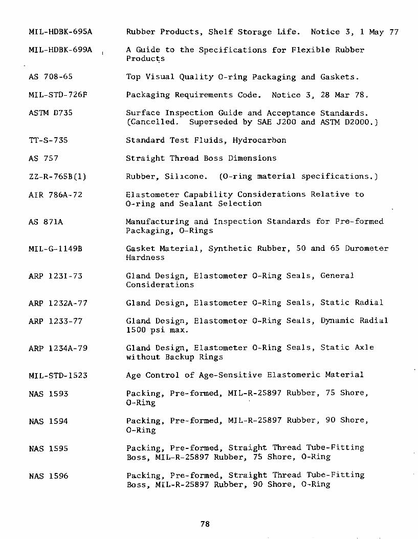
MIL-HDBK-695A Rubber Products, Shelf Storage Life. Notice 3, 1 May 77
MIL-HDBK-699A A Guide to the Specifications for Flexible RubberProducts
AS 708-65 Top Visual Quality O-ring Packaging and Gaskets.
MIL-STD-726F Packaging Requirements Code. Notice 3, 28 Mar 78.
ASTM D735 Surface Inspection Guide and Acceptance Standards.(Cancelled. Superseded by SAE J200 and ASTM D2000.)
TT-S-735 Standard Test Fluids, Hydrocarbon
AS 757 Straight Thread Boss Dimensions
ZZ-R-765B(l) Rubber, Silicone. (0-ring material specifications.)
AIR 786A-72 Elastometer Capability Considerations Relative toO-ring and Sealant Selection
AS 871A Manufacturing and Inspection Standards for Pre-formedPackaging, O-Rings
MIL-G-1149B Gasket Material, Synthetic Rubber, 50 and 65 DurometerHardness
ARP 1231-73 Gland Design, Elastometer O-Ring Seals, GeneralConsiderations
ARP 1232A-77 Gland Design, Elastometer O-Ring Seals, Static Radial
ARP 1233-77 Gland Design, Elastometer O-Ring Seals, Dynamic Radial1500 psi max.
ARP 1234A-79 Gland Design, Elastometer O-Ring Seals, Static Axlewithout Backup Rings
MIL-STD-1523 Age Control of Age-Sensitive Elastomeric Material
NAS 1593 Packing, Pre-formed, MIL-R-25897 Rubber, 75 Shore,O-Ring
NAS 1594 Packing, Pre-formed, MIL-R-25897 Rubber, 90 Shore,O-Ring
NAS 1595 Packing, Pre-formed, Straight Thread Tube-FittingBoss, MIL-R-25897 Rubber, 75 Shore, O-Ring
NAS 1596 Packing, Pre-formed, Straight Thread Tube-FittingBoss, MIL-R-25897 Rubber, 90 Shore, O-Ring
78

NAS 1613 Packing, O-Ring, Phosphate Ester Resistant
AIR 1707 Patterns of O-Ring Failures, Aerospace InformationReport
ASTM D2000-80 Rubber Products in Automotive Applications, 28 Mar 80
AMS 2817B-75 Packaging and Identification, Pre-formed Packaging
MIL-R-3065D Rubber, Fabricated Parts
AMS 3200E Rubber, Nitrile, Petroleum-Base, Hydraulic FluidResistance 55-65
AMS 3201G-75 Rubber, Nitrile, Dry Heat Resistant 35-45
AMS 3202G-75 Rubber, Nitrile, Dry Heat Resistant 55-65
MIL-G-4343B Grease, Pneumatic System
MIL-Q-9858A Handwheel, Ordnance
MS 9970 Packing, Pre-formed, AMS 7279, O-Ring
MIL-P-25732 Packing, Pre-formed, Petroleum Hydraulic FluidResistant, Limited Service at 275'F (135 0 C)
MS 28775D Packing, Pre-formed, Hydraulic, Plus 275 0 F (0-Ring)
MS 28778B Packing, Pre-formed, Straight Thread Tube FittingBoss
MS 28784D Packing, O-Ring, Hydraulic, 275F (Cancelled;superseded by MS 28775)
MS 28900 Packing, Pre-formed, for Electrical Use. (For sizes,see Reference 28)
MIL-P-4861B(4) Packing, Pre-formed, Rubber, Packaging of
MIL-P-5315B(l) Packing, Pre-formed, Hydrocarbon Fuel Resistant
MIL-P-5510C Packing, Pre-formed, Straight Thread Tube FittingBoss, Type 1 Hydraulic (-65o to 160 0 F)
MIL-G-5514F Gland Design, Packings, Hydraulic, General Require-ments For
MIL-P-5516C(2) Packing, Pre-formed, Petroleum Hydraulic FluidResistant, 160 0 F. (Use MIL-P-25732 or MIL-P-83461)
79

AN6227 Packing, O-Ring Hydraulic (Rev. 8). (Compound per MIL-P-SS16).O-ring dimensions correspond with AS568, but dash numbersare different. The table shows AN and AS correspondingdash numbers.
AN AS AN AS AN AS AN AS6227 568 6227 568 6227 568 6227 568
1 006 23 218 45 342 67 4402 007 24 219 46 343 68 4413 008 25 220 47 344 69 4424 009 26 221 48 345 70 4435 010 27 222 49 346 71 444
6 011 28 325 50 347 72 4457 012 29 326 51 348 73 4468 110 30 327 52 349 74 4479 111 31 328 53 426 75 448
10 112 32 329 54 427 76 449
11 113 33 330 55 428 77 45012 114 34 331 56 429 78 45113 115 35 332 57 430 79 45214 116 36 333 58 431 80 45315 210 37 334 59 432 81 454
16 211 38 335 60 433 82 45517 212 39 336 61 434 83 45618 213 40 337 62 435 84 45719 214 41 338 63 436 85 45820 215 42 339 64 437 86 459
21 216 43 340 65 438 87 46022 217 44 341 66 439 88 42S
.Qn

AN6230 Gasket, O-ring Hydraulic (Rev. 8). (Compound per MIL-P-5516).O-ring dimensions correspond with AS 568, but dash numbersare different. The table shows AN and AS correspondingdash numbers.
AN AS AN AS AN AS AN AS6230 568 6230 568 6230 568 6230 568
1 223 14 236 27 249 40 2622 224 15 237 28 250 41 2633 225 16 238 29 251 42 2644 226 17 239 30 252 43 2655 227 18 240 31 253 44 266
6 228 19 241 32 254 45 2677 229 20 242 33 255 46 2688 230 21 243 34 256 47 2699 231 22 244 35 257 48 270
10 232 23 245 36 258 49 271
11 233 24 246 37 259 50 27212 234 25 247 38 260 51 27313 235 26 248 39 261 52 274
RI"

15.2 Selected References
1. Smoley, E.M., "Sealing with Gaskets," Machine Design, October 27,1966.
2. Andrews, J.N., "Hollow Metal 0-rings," Product Engineering,November 26, 1962.
3. Freeman, A.R., "Gaskets for High Pressure Vessels," ASME, Paper No.52-11RD-5.
4. Elonka, S., "Gaskets," Power, March 1954.
5. "Design Manual on Nonmetallic Gaskets," Machine Design, 1954.
6. "Seals Reference Issue," Machine Design, June 19, 1969.
7. Warring, R.H., Seals and Packings, Trade and Technical Press, Ltd.,Norden, Surrey, England, 1967.
8. Denny, D.F. and C.M. White, "The Sealing Mechanism of FlexiblePackings," London: His Majesty's Stationery Office, 1948.
9. Bridgman, P.E., The Physics of High Pressure, Macmillan Co.,New York, 1931.
10. Barbarin, R., "Keeping Seals Tight," Machine Design, August 26,1976, pp. 92-93.
11. Ratelle, W., "Seal Selection Beyond 'Standard Practice,.'" MachineDesign, January 20, 1977, pp. 133-137.
12. Wilson, J.V., "Sonar Cable and Connector Problems," FY-78 STRIPTASK C-1 NRL; Tech. Memo. No. 43-79-01, Civil Engineering Labora-tory, Port Hueneme, California 93043.
13. Sandwith, C.J. "Performance/Failure Analysis of Acoustic ArrayConnectors After 6-10 Years of Service," OCEANS 78-74-76790,September 1978, pp. 273-286.
14. Mark's Standard Handbook for Mechanical Engineers, Seventh Edition,Sections 6 and 8, 1958.
15. O-Ring Handbook ORD-5700, Parker Hannifin Corporation, Lexington,Kentucky.
16. O-Ring Guide for Industrial Maintenance Men, Parker HannifinCorporation, Lexington, Kentucky.
17. O-Ring Guide for Aircraft Maintenance Men, Parker Hannifin Cor-poration, Lexington, Kentucky.
R2

18. Abo, M.M., "Analysis of Array Components Recovered at St. Croix,VI," NAVTORPSTA Report 1332, Naval Torpedo Station, Keyport,Washington, May 1977.
19. Reference Manual on Interference Seals and Connectors for UnderseaElectrical Applications, prepared by the Applied Physics Laboratoryof the University of Washington for the Naval Facilities EngineeringCommand, Chesapeake Division (available from NTIS, 5285 Port RoyalRoad, Springfield, Virginia 22161; ref. Publ. ADA 036841), June 1976.
20. Jenkins, J.F., "Inspection of Objects Retrieved from the DeepOcean - AUTEC Acoustic Array," Technical Note 1424, Civil EngineeringLaboratory, Port Hueneme, California, February 1976.
21. "Design Recommendations for Pressure Proof Plug to Receptacle Seals,"Static Seals Panel, Undersea Cable and Connector Committee, MarineTechnology Society (assembled by Raymond Haworth, Carl Schweichert,and Edward Swartz), July 23, 1971.
22. Atkinson, W.B., "Gasket Materials for Electrical Equipment,"Product Engineering, December 1949.
23. Frazier, E. C., "Designing for Economical Gasketing," ProductEngineering, July 1951.
24. Bolz, R.W., "Gaskets in Design," Machine Design, March 1945.
25. Thron, F.C., "Compression and Stress Decay in Rubber Gaskets,"ASTM Bulletin, October 1941.
26. Haworth, R.F., "Handbook for Connector and Cable Harness Design,"(in preparation).
27. Sandwith, C.J., "Painting O-Ring Sealing Surfaces to PreventCorrosion," in Corrosion Control by Organic Coatings, Henry Leidheiser,Jr., ed., National Association of Corrosion Engineers, 1981, pp. 285-294.
28. "National O-Ring Design Guide," OR-ISR, Federal Mogul Corp.,1975 (rev. 1979).
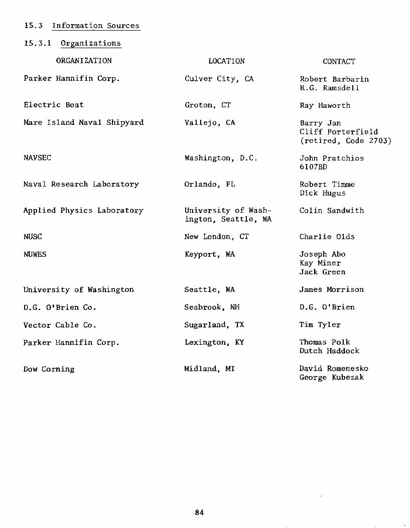
15.3 Information Sources
15.3.1 Organizations
ORGANIZATION LOCATION CONTACT
Parker Hannifin Corp. Culver City, CA Robert BarbarinR.G. Ramsdell
Electric Boat Groton, CT Ray Haworth
Mare Island Naval Shipyard Vallejo, CA Barry JanCliff Porterfield(retired, Code 2703)
NAVSEC Washington, D.C. John Pratchios6107BD
Naval Research Laboratory Orlando, FL Robert TimmeDick Hugus
Applied Physics Laboratory University of Wash- Colin Sandwith
ington, Seattle, WA
NUSC New London, CT Charlie Olds
NUWES Keyport, WA Joseph AboKay MinerJack Green
University of Washington Seattle, WA James Morrison
D.G. O'Brien Co. Seabrook, NH D.G. O'Brien
Vector Cable Co. Sugarland, TX Tim Tyler
Parker Hannifin Corp. Lexington, KY Thomas PolkDutch Haddock
Dow Corning Midland, MI David RomeneskoGeorge Kubezak
84

15.3.2 Standards and Specifications
1. All military listings in the Department of Defense Index of Standardsand Specifications can be ordered, preferably with DD Form 1425, from:
Commanding OfficerNaval Publications and Forms CenterATTN: NPFC 30155801 Tabor AvenuePhiladelphia, PA 19120
Refer to Department of Defense Index of Specifications and Standards(DODISS), Part I and Part II, for a complete alphabetical listingand other source information. DODISS is available to militaryactivities from:
Commanding OfficerNaval Publications and Forms Center5801 Tabor AvenuePhiladelphia, PA 19120
and to private industry and individuals from:
Superintendent of DocumentsU.S. Government Printing OfficeWashington, D.C. 20402
2. Federal Standardization Documents (TT-, ZZ-, and others) areavailable from:
General Services AdministrationSpecification and Consumer Information
Distribution Section (WFSIS)Washington Navy Yard, Bldg. 197Washington, D.C. 20407
3. ANSI standards can be ordered from:
American National Standards Institute (ANSI)Sales Department1430 BroadwayNew York, NY 10018
4. AS, ARP, AMS, and AIR sets of standards can be ordered from:
Society of Automotive Engineers, Inc. (SAE)Dept. 331400 Commonwealth DriveWarrendale, PA 15096
85