oak ridge telephone national laboratoryinfo.ornl.gov/sites/publications/files/pub2501.pdforder of...
TRANSCRIPT

OAK RIDGE
NATIONAL LABORATORY
MANAGED BY UT-BATTELLEFOR THE DEPARTMENT OF ENERGY
DOCUMENT AVAILABILITY
Reports produced after January 1, 1996, are generally available free via the U.S. Department of Energy (DOE) Information Bridge.
W eb site http://www.osti.gov/bridge
Reports produced before January 1, 1996, may be purchased by members of the public from the following source.
National T echnical Information Service5285 Port Royal RoadSpringfield, V A 22161T elephone 703-605-6000 (1-800-553-6847) TDD 703-487-4639 Fax 703-605-6900E-mail [email protected]
Web site http://www.ntis.gov/support/ordernowabout.htm
Reports are available to DOE employees, DOE contractors, Energy Technology Data Exchange (ETDE) representatives, and
International Nuclear Information System (INIS) representatives from the following source.
Of fice of Scientific and Technical InformationP .O. Box 62Oak Ridge, TN 37831 Telephone 865-576-8401 Fax 865-576-5728 E-mail [email protected] Web site http://www.osti.gov/contact.html
This report was prepared as an account of work sponsored by an agency of the United States Government. Neither the United States Government nor any agency thereof, nor any of their employees, makes any warranty , express or implied, or assumes any legal liability or responsibility for the accuracy , completeness, or usefulness of any information, apparatus, product, or process disclosed, or represents that its use would not infringe privately owned rights. Reference herein to any specific commercial product, process, or service by trade name, trademark, manufacturer , or otherwise, does not necessarily constitute or imply its endorsement, recommendation, or favoring by the United States Government or any agency thereof. The views and opinions of authors expressed herein do not necessarily state or reflect those of the United States Government or any agency thereof.
ORNL-27 (4-00)

DOCUMENT AVAILABILITY
Reports produced after January 1, 1996, are generally available free via the U.S. Department of Energy (DOE) Information Bridge.
Web site http://www.osti.gov/bridge
Reports produced before January 1, 1996, may be purchased by members of the public from the following source.
National Technical Information Service5285 Port Royal RoadSpringfield, VA 22161Telephone 703-605-6000 (1-800-553-6847)TDD 703-487-4639Fax 703-605-6900E-mail [email protected] site http://www.ntis.gov/support/ordernowabout.htm
Reports are available to DOE employees, DOE contractors, Energy Technology Data Exchange (ETDE) representatives, and International Nuclear Information System (INIS) representatives from the following source.
Office of Scientific and Technical InformationP.O. Box 62Oak Ridge, TN 37831Telephone 865-576-8401Fax 865-576-5728E-mail [email protected] site http://www.osti.gov/contact.html
This report was prepared as an account of work sponsored by an agency of the United States Government. Neither the United States Government nor any agency thereof, nor any of their employees, makes any warranty, express or implied, or assumes any legal liability or responsibility for the accuracy, completeness, or usefulness of any information, apparatus, product, or process disclosed, or represents that its use would not infringe privately owned rights. Reference herein to any specific commercial product, process, or service by trade name, trademark, manufacturer, or otherwise, does not necessarily constitute or imply its endorsement, recommendation, or favoring by the United States Government or any agency thereof. The views and opinions of authors expressed herein do not necessarily state or reflect those of the United States Government or any agency thereof.

AN ASSESSMENT OF ORNL PIE CAPABILITIES FOR THE AGR PROGRAM
CAPSULE POST IRRADIATION EXAMINATION
Robert N. Morris
September 2006
Prepared by OAK RIDGE NATIONAL LABORATORY
P.O. Box 2008 Oak Ridge, Tennessee 37831-6285
managed by UT-Battelle, LLC
for the U.S. DEPARTMENT OF ENERGY
under contract DE-AC05-00OR22725

CONTENTS
Figures ........................................................................................................................ v Tables ........................................................................................................................ vi
Acronyms ........................................................................................................................ vii Executive Summary.......................................................................................................... viii
1.0 Introduction ................................................................................................................ 1 1.1 Building 3525..................................................................................................... 1
1.2 Other Buildings .................................................................................................. 7 1.2.1 Building 3025E.......................................................................................... 7 1.2.2 Building 4501............................................................................................ 8 1.2.3 Building 4508 LAMDA Facility ................................................................ 9
2.0 General PIE Task Flow ............................................................................................... 10 2.1 Data Task Matrix................................................................................................ 11
3.0 Current Hot Cell Status for the AGR Program............................................................. 12 3.1 AGR Program Plan Task Requirements.............................................................. 13
3.1.1 AGR PIE Task-1....................................................................................... 14 3.1.2 AGR PIE Task-2........................................................................................ 15 3.1.3 AGR PIE Task-3....................................................................................... 16 3.1.4 AGR PIE Task-4....................................................................................... 16 3.1.5 AGR PIE Task-5....................................................................................... 17 3.1.6 AGR PIE Task-6....................................................................................... 17 3.1.7 AGR PIE Task-7....................................................................................... 18 3.1.8 AGR PIE Task-8....................................................................................... 18 3.1.9 AGR PIE Task-9....................................................................................... 19 3.1.10 AGR PIE Task-10................................................................................... 19 3.1.11 AGR PIE Task-11................................................................................... 20 3.1.12 AGR PIE Task-12................................................................................... 20 3.1.13 AGR PIE Task-13................................................................................... 21 3.1.14 AGR PIE Task-14................................................................................... 21 3.1.15 AGR PIE Task-15................................................................................... 22 3.1.16 AGR PIE Task-16................................................................................... 22 3.1.17 AGR PIE Task-17................................................................................... 23 3.1.18 AGR PIE Task-18................................................................................... 23 3.1.19 AGR PIE Task-19................................................................................... 24 3.1.20 AGR PIE Task-20................................................................................... 24 3.1.21 AGR PIE Task-21................................................................................... 25 3.2 General Functional Requirements....................................................................... 25

iv
4.0 Specific Task Equipment Specification and Current Status.......................................... 32
4.1 Test Train Gamma Scanning .............................................................................. 32 4.2 Test Train Disassembly and Component Removal .............................................. 33
4.3 Metrology ......................................................................................................... 34 4.4 Leach-Burn-LeacH Apparatus ............................................................................ 35
4.5 Irradiated Microsphere Gamma Analyzer (IMGA) ............................................. 36 4.6 Metallographic Examination............................................................................... 37
4.7 SEM/Microprobe................................................................................................ 38 4.8 CO/CO2 Particle Gas Analyzer ........................................................................... 39
4.9 Compact Reactivation ........................................................................................ 39 4.10 Annealing Furnace ........................................................................................... 40
4.11 Graphite Sorptivity/Diffusion Data Collection .................................................. 41 4.12 Material Properties Tools.................................................................................. 42
4.13 Hot Cell Resources ........................................................................................... 42 4.14 Equipment Standardization............................................................................... 43
5.0 Path Forward............................................................................................................... 44 6.0 Summary..................................................................................................................... 45
References ........................................................................................................................ 46 Appendix A. Data Test Matrix .......................................................................................... A-1
Appendix B. Minimal AGR PIE Preparation..................................................................... B-1

v
FIGURES
Figure 1 Building 3525 at ORNL................................................................................... 2 Figure 2 Hot Cell layout within Building 3525. ............................................................. 3 Figure 3 SEM cubicle. ................................................................................................... 4
Figure 4 SEM with shielding loading device.................................................................. 5 Figure 5 The IMGA cubicle used for coated particle fuel investigations. Front view
(left) showing the manipulators and side view (left) showing the counting port......................................................................................................................... 5
Figure 6 The IMGA device used for coated particle fuel investigations.......................... 6 Figure 7 The CCCTF cubicle......................................................................................... 6
Figure 8 Annealing furnace. .......................................................................................... 7 Figure 9 A Typical Building 3025E testing station......................................................... 9
Figure 10 Quadrapole spectrometer and glovebox areas in Building 4501........................ 9 Figure 11 LAMDA lab. ................................................................................................... 10

vi
TABLES
Table 1. Functional Breakdown of the PIE Tasks ............................................................. 26 Table 2. Order of Magnitude Gamma Scanner Cost Evaluation For Full Train Scanning
(Hot Cell Time Not Included) .......................................................................... 33 Table 3. Order of Magnitude Disassembly Jig Cost Evaluation (Hot Cell Time Not
Included) ......................................................................................................... 34 Table 4. Order of Magnitude Automated Metrology Jig Cost Evaluation
(Hot Cell Time Not Included) .......................................................................... 35 Table 5. Order of Magnitude LBL Cost Evaluation (Hot Cell Time Not Included) ........... 35
Table 6. Order of Magnitude IMGA Cost Evaluation (Hot Cell Time Not Included) ........ 37 Table 7. Order of Magnitude Partial IMGA Cost Evaluation (Hot Cell Time Not
Included) ......................................................................................................... 37 Table 8. Order of Magnitude Metallograph Replacement Cost Evaluation
(Hot Cell Time Not Included) .......................................................................... 38 Table 9. Order of Magnitude Second SEM Upgrade Cost Evaluation (Hot Cell Time Not
Included) ......................................................................................................... 38 Table 10. Order of Magnitude CO/CO2 Particle Gas Analyzer Cost Evaluation
(Hot Cell Time Not Included) .......................................................................... 39 Table 11. Order Of Magnitude Reactivation Concept Cost Evaluation ............................ . 40
Table 12. Order of Magnitude Airlock Annealing Furnace Cost Evaluation (Hot Cell Time Not Included) .......................................................................... 40
Table 13. Order of Magnitude Oxidizing Annealing Furnace Cost Evaluation (Hot Cell Time Not Included) .......................................................................... 41
Table 14. Order of Magnitude Micro-Gamma Scanner Cost Evaluation (Hot Cell Time Not Included) .......................................................................... 42
Table 15. Order of Magnitude Hot Cell Time Costs. ........................................................ 43

vii
ACRONYMS AGR Advance Gas-Cooled Reactor ATR Advanced Test Reactor CCCTF Core Conduction Cooldown Test Facility CoC Certificate of Compliance DDN Design Data Need DTM Data Task Matrix EDS Energy Dispersive Spectrometry ES&H Environment, Safety, and Health HFIR High Flux Isotope Reactor IFEL Irradiated Fuels Examination Laboratory IMET Irradiated Materials Examination and Testing IMGA Irradiated Microsphere Gamma Analyzer INL Idaho National Laboratory HEPA High Efficiency Particular Air LAMDA Low Activity Materials Development & Analysis LBL Leach-Burn-Leach LWR Light Water Reactor NEPA National Environmental and Protection Act ORNL Oak Ridge National Laboratory OPyC Outer Pyrocarbon (layer) PGA Particle Gas Analyzer PIE Post-Irradiation Examination QA Quality Assurance QC Quality Control R/B Release to Birth Ratio (fission gases) SAR Building Safety Analysis Review SEM Scanning Electron Microscope SNF Spent Nuclear Fuel WDS Wavelength Dispersive Spectrometry
viii
EXECUTIVE SUMMARY ORNL has facilities and experienced staff that can execute the Advanced Gas Reactor (AGR) Post Irradiation Examination (PIE) task. While the specific PIE breakdown needs to be more formally defined, the basic outline is clear and the existing capabilities can be assessed within the needs of the tasks defined in the program plan. A one-to-one comparison between the program plan tasks and the current ORNL PIE status was conducted and while some shortcomings were identified, the general capability is available. Specific upgrade needs were identified and reviewed. A path forward was formulated. Building 3525 is available for this work and this building is equipped with the tools necessary for coated particle fuel PIE, but some of the analysis tools are no longer state-of-the-art and others are the near the end-of-life. This report identifies these tools and provides rough estimates of the costs required to update and replace them. In addition, other ORNL buildings are available to support Building 3525 in specialized tasks along with the normal laboratory infrastructure. Before the AGR management embarks on any equipment development effort, the PIE tasks should be updated against current program (modeling and data) needs and better defined so that the items to be measured, their measurement uncertainties, and throughput needs can be reviewed. A Data Task Matrix (DTM) should be prepared so that the program data needs can be compared against the identified PIE tasks and what is practical in the hot cell environment to make sure nothing is overlooked. Finally, if the PIE is to be conducted at multiple sites, thought should be given to the development of standardized equipment designs between sites to avoid redundant design efforts and different measurement techniques. This is a potentially cost saving effort that can also avoid data inconsistencies.

1
1.0 INTRODUCTION The purpose of this report is to determine the Post Irradiation Examination (PIE) tools required for the PIE of the Advanced Gas-Cooled Reactor (AGR) series of capsules and the present inventory of these tools at Oak Ridge National Laboratory (ORNL) [1]. These capsules will be irradiated in the Advanced Test Reactor (ATR) at the Idaho National Laboratory (INL) and will contain gas-cooled reactor fuel and test components. The current program plan contains only an upper level description of the PIE plans, but this description along with ORNL experience from past gas-cooled reactor fuel PIE efforts allows us to make a reasonable estimate of the tools required and the work to be done. Historically, efforts of this nature have required all the usual hot cell tools along with several specialized tools for handling coated particle fuel. Due to reduced programmatic funding in this area over the past decade, much of the general hot cell tooling as well as the specialized particle handling tools are in need of maintenance, upgrading, or replacement. In addition, the increased emphasis on environmental, safety, and health issues, as well as the economic constraints of increased efficiency demand that a close look be taken not only at the tool inventory, but how this work is conducted. Thus, some of the equipment changes and upgrades may be due to demands outside of this program and capital/labor tradeoffs, not just programmatic data needs. For example, waste minimization issues may favor nondestructive techniques, and schedule and cost issues may result in a need for more automation. The PIE will require the support of not just the hot cell staff, but ancillary groups as well. These groups are often transparent to the program, but they must be acknowledged because their services must be incorporated into the cost and schedule for the task planning. Prior to any work being conducted at the hot cell, the program must be sure the National Environmental and Protection Act (NEPA) documentation has been completed, nuclear criticality and radiation exposure conditions satisfied, isotope shipping forms completed, lifting and rigging requirements satisfied, calibration needs satisfied, and quality control plans implemented. In addition, spent fuel handling and waste disposal services will be required.
1.1 BUILDING 3525 The Irradiated Fuels Examination Laboratory (IFEL), Building 3525, has a long history of fuel research and examination. It is in the Bethel Valley portion of ORNL, approximately 8 miles southwest of the city of Oak Ridge, Tennessee. Over a period of three decades this facility has handled a wide variety of nuclear fuels including aluminum clad research reactor fuel, both stainless and zircaloy clad Light Water Reactor (LWR) fuel, coated-particle gas cooled reactor fuel (most recently HRB and NPR capsules), and numerous one of a kind fuel test experiments. It has been the primary US PIE facility for

2
examination of coated particle fuel. In addition, the facility has also performed iridium isotope processing and irradiated structural materials capsule disassembly. Figure 1 shows an outside view of the Building.
Fig. 1. Building 3525 at ORNL The IFEL contains a large horseshoe-shaped array of hot cells which are divided into three work areas (see Figure 2). The hot cells are constructed of 3-ft thick high density concrete walls with oil filled lead glass viewing windows. The inside surfaces of the cell bank are lined with stainless steel to provide containment of particulate matter and to facilitate decontamination. Special penetrations in the front and back of the cells are provided for the sealed entry of services such as instrument lines, lights, and electrical power. A pair of manipulators is located at each of 15 window stations for remote cell operations and periscopes allow for magnified views of in-cell objects. Heavy objects within each cell bank can be moved by electromechanical manipulators or a 3 ton crane. Fuel materials enter and leave the cells through three shielded transfer stations provided at the rear face of the North cell. Two small diameter (6.5 & 14.5 in) horizontal transfer stations are used for small objects (less than 8 ft in length). Items (usually casks) up to 4 by 4 by 6 ft in size can be transferred through the shielded air-lock door system. In addition, with modifications (planned for early 2007) for cask handling, it will be possible to handle full length light water reactor fuel rods in the East Cell.

3
Fig. 2. Hot Cell layout within Building 3525. The remainder of the building outside the hot cell complex is subdivided into: (1) the charging area; (2) the equipment maintenance air lock areas; (3) the operating area; (4) the truck unloading area; (5) the rooms housing supporting mechanical equipment; (6) the decontamination area; (7) the hot equipment storage area; (8) Room 120 which contains hoods for small projects, and (9) the office area in the front of the building for staff. The shielded decontamination area and the hot equipment storage area, located on the second floor of the building, are connected via hatches to the cells below. A maintenance area incorporating glove box facilities for servicing equipment adjoins the decontamination area. Sliding doors separate the decontamination area, storage area, and glove maintenance room; a remote crane system provides for retrieval of equipment into and transfer of items between these second floor facilities. Equipment may be transferred between cells through the second floor pathway. An upper level of the second floor houses ventilation system ducts, control valves, high efficiency particulate air filters, heat exchangers, and air inlets for the equipment storage area, the decontamination area, and the glove maintenance area.

4
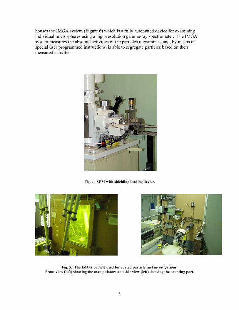
Gases and particulates exhausted from the cell complex are completely contained and shielded until subjected to sufficient filtration to ensure safe stack disposal. The cell air is maintained at negative pressure with respect to the operating areas to ensure confinement. Liquid effluent from the hot cells is handled in a batch mode for disposal to the ORNL low-level liquid waste system. The IFEL also has other facilities outside the main bank of cells. Room 120 contains hoods, preparation tools, and examination equipment for conducting hands-on low level tasks in a contamination zone. Three free standing shielded cubicles are located on the first and second floors of the building which contain specialized equipment associated with PIE. The Scanning Electron Microscope (SEM) cubicle (Figure 3) is located on the second floor above the West Hot Cell and is connected to the West Cell by an in-cell shielded elevator. The cubicle contains a precision balance and a vacuum sputter coating system for gold coating of SEM specimens. A special transfer port is mounted on the side of the cubicle which allows shielded handling of specimens to be loaded into the SEM system located adjacent to the cubicle. The SEM currently available is a JEOL JXA 840A system with both wavelength dispersive spectrometry (WDS) and energy dispersive spectrometry (EDS) capability. Radioactive specimens up to 1 R/hr (near contact) can be examined in this system. Figure 4 shows the SEM.
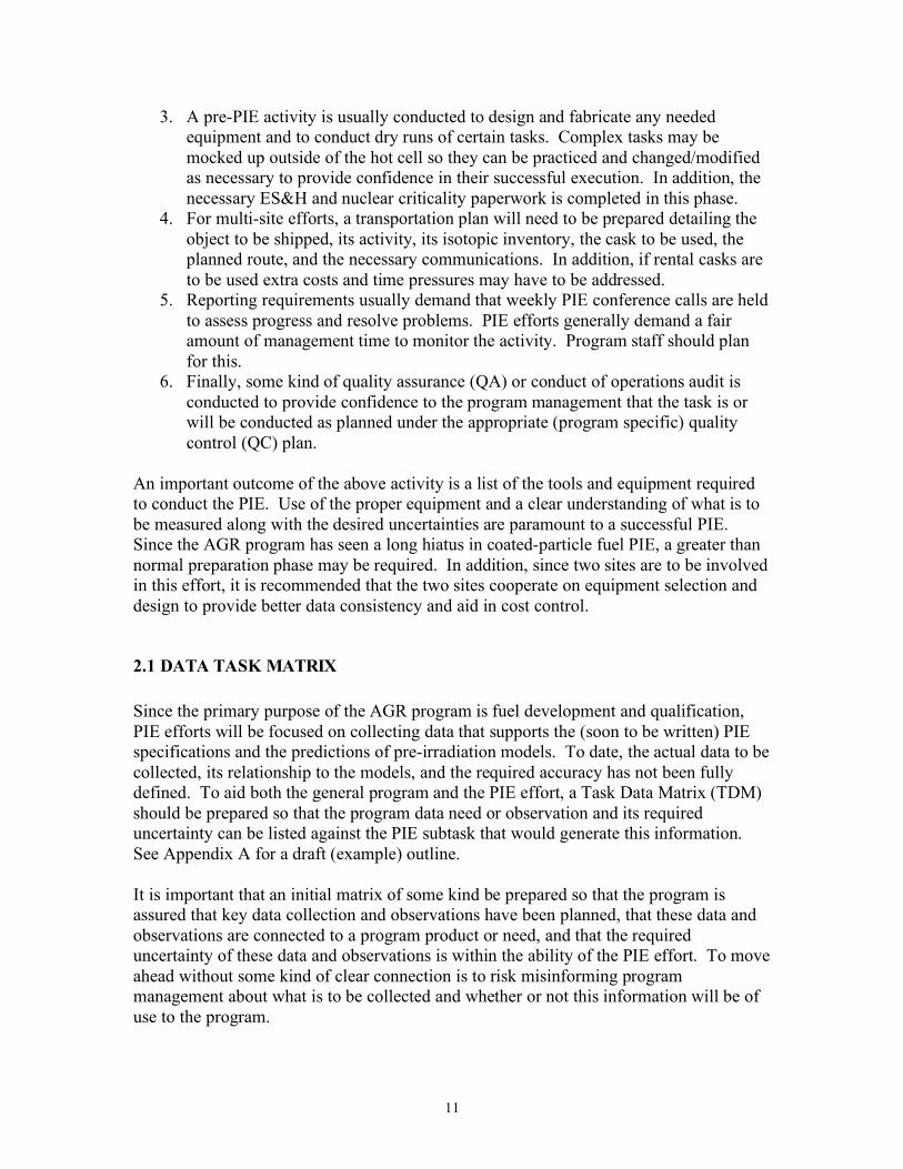
Fig. 3. SEM cubicle. The Irradiated Microsphere Gamma Analyzer (IMGA) cubicle (Figure 5) is located on the second floor above the East Hot Cell and is connected to the East Cell by an in-cell shielded elevator. The cubicle contains several pieces of equipment specially designed for handling individual coated particles. The cubicle has a shielded stereo-microscope with a 3 axis stereo-stage and micro-manipulator for handling individual particles. It also
5
houses the IMGA system (Figure 6) which is a fully automated device for examining individual microspheres using a high-resolution gamma-ray spectrometer. The IMGA system measures the absolute activities of the particles it examines, and, by means of special user programmed instructions, is able to segregate particles based on their measured activities.
Fig. 4. SEM with shielding loading device.
Fig. 5. The IMGA cubicle used for coated particle fuel investigations.
Front view (left) showing the manipulators and side view (left) showing the counting port.

6
Fig. 6. The IMGA device used for coated particle fuel investigations.
The Core Conduction Cooldown Test Facility (CCCTF) cubicle (Figure 7) is located on the first floor of the IFEL. This is a general purpose cubicle that is kept clean and used for a variety of functions.
Fig. 7. The CCCTF cubicle. The function of most interest to this program is the annealing furnace (Figure 8), which is used for accident testing of coated particle fuel. The furnace is operated in the CCCTF cubicle which contains the necessary utilities and links to the control system and gas traps.

7
Fuel samples to be tested are transferred to and from the cubicle using small shielded casks. The furnace is capable of temperatures up to 1800ºC when using an inert atmosphere such as helium.
Fig. 8. Annealing furnace. In addition to the furnace and cubicle, the system includes a power supply, a control and data logging system, a sweep gas source and a rather complex gas trapping and gamma counting system. This system was used for the HRB-22 series of heatup tests and underwent an upgrade to conduct later tests [12].
1.2 OTHER BUILDINGS While Building 3525 is the major building involved in fuel PIE work, three other buildings often participate in these tasks and contain a host of specialized equipment and experienced personnel.
1.2.1 Building 3025E The Irradiated Materials Examination and Testing (IMET) hot cell facility is located in Building 3025E. These hot cells are the primary mechanical testing and examination facility at ORNL for highly irradiated structural alloys and ceramics. The six interconnected (shielded drawers/doors) steel-lined hot cells contain 320 square feet of

8
work space and are maintained as a low alpha contamination facility (<70 dpm per 100 cm2) to facilitate transfer of specimens to other radiological laboratories after testing or sorting. An additional 600 square feet of work space for test equipment control systems and staff work stations is located in a contamination-free area in front of the hot cells. The cells offer easy access for equipment installation and maintenance via removable roof plates for large equipment and doors at the rear of the cells for smaller equipment and personnel entry. All of the cells are equipped with Level 8 (or better) manipulators. Video cameras and/or Kollmorgen wall periscopes are located in most of the cells to assist in visual identification of specimens and for equipment troubleshooting. The cell exhaust is connected to a High Efficiency Particulate Air (HEPA) filtered ventilation system and the drains to the low-level liquid waste system. Plant air, process water, liquid nitrogen, inert gas, and electrical power are available in all cells. Internet connections are used to transfer data from the equipment to internal and external users. A radiological specimen preparation area is located adjacent to the hot cells, consisting of three shielded glove boxes and a chemical hood with HEPA ventilation and connections to the ORNL low-level liquid waste system. This specimen preparation facility is used for preparation of transmission electron microscopy specimens and other specialized activities. Typical testing functions include tensile testing, laser profilometry, creep testing, Charpy impact and fracture toughness testing, fatigue testing, capsule disassembly, density measurements, microscopic examination, grinding, polishing, welding, shearing, machining, sawing, photography, and video examination. Equipment includes a laser profilometer, a screw driven Instron machine (20 kip load frame) with a turbo pumped high temperature (up to 1350ºC) furnace chamber that is capable of achieving pressures below 10-7 torr, an automated ball indentation flow properties test system (screw driven frame), a Mitutoyo automated micro-indentation hardness tester (model AAV-500, capable of Vickers or Knoop indentations), a Tinius-Olsen Charpy impact machine, two MTS servo-hydraulic testing machines, an FEI (Philips) XL30 scanning electron microscope equipped with a LaB6 filament, and an EMCO TM02 computer-numerically controlled (CNC, CAD/CAM) milling machine that is programmable for fully automated machining operations. Figure 9 shows a typical testing station. 1.2.2 Building 4501 Radiochemical analysis is performed in Building 4501. This facility and staff can perform the necessary chemical separations and mass spectrometric operations required for the isotopic analysis of fuel and fission product specimens. Figure 10 shows the mass quadrapole and glovebox area. This facility also contains a variety of other analytic instrumentation and fully equipped radiological counting room, and can handle a wide variety of specimens. A specimen preparation area is available for prep work; because of activity limitations, some high level prep work may have to be done at Building 3525.

9
Fig. 9. A Typical Building 3025E testing station.
Fig. 10. Quadrapole spectrometer and glovebox areas in Building 4501.
1.2.3 Building 4508 LAMDA Facility The Low Activity Materials Development & Analysis (LAMDA) facility is a multipurpose laboratory for evaluation of low activity materials such as irradiated nuclear grade graphite, low activation metals, and SiC. The most commonly conducted work includes mechanical testing, optical and scanning electron microscopy, densitometry, metallography, and thermal and electrical conductivity. The lab contains load frames, high vacuum furnaces, a scanning calorimeter, a flash diffusivity system, resistivity tester, an SEM, and density determination devices. Work can be conducted on tabletops, hoods, or glove boxes, depending on the specimen activity; this equipment may be of interest to the AGR PIE task if low level specimens are available or can be prepared from the major test specimens. This lab is also a beta/gamma area; work with alpha material may be possible. Figure 11 is a view of this lab.

10
Fig. 11. LAMDA lab.
2.0 GENERAL PIE TASK FLOW Prior to the commencement of the PIE activity, a rather extensive planning task is executed to outline the required tasks, the facilities required, the equipment required for the tasks, the QC level, and the reporting required. A typical activity would proceed as follows:
1. The test capsule/train would be reviewed along with its irradiation conditions and abnormalities seen during the irradiation. This review would be summarized in the PIE report and would include drawings showing the construction of the test capsule train, materials of construction, items of interest, expected changes during irradiation, isotope inventory, and any special handling precautions. The irradiation history would document the actual conditions seen by the capsule, the sweep gas activity, and any unexpected behavior. This effort usually consists of two reports, a pre-irradiation capsule description along with the expected irradiation plan and a later post-irradiation report describing how the irradiation proceeded and any problems encountered.
2. A PIE plan would be prepared detailing the method of opening the capsule, removing the specimens of interest, inspecting them, item storage, item testing (if any), specific measurement methods, any special needs, and finally, reporting. For the AGR capsule trains, this report may require extensive disassembly instructions because of the complex nature of the capsule train. In addition, the fuel accident testing is complex as well. Thus, two or more reports may be required for this task, the first being the disassembly and metrology of the capsule train, and the second containing the detailed description of the accident testing.
11
3. A pre-PIE activity is usually conducted to design and fabricate any needed equipment and to conduct dry runs of certain tasks. Complex tasks may be mocked up outside of the hot cell so they can be practiced and changed/modified as necessary to provide confidence in their successful execution. In addition, the necessary ES&H and nuclear criticality paperwork is completed in this phase.
4. For multi-site efforts, a transportation plan will need to be prepared detailing the object to be shipped, its activity, its isotopic inventory, the cask to be used, the planned route, and the necessary communications. In addition, if rental casks are to be used extra costs and time pressures may have to be addressed.
5. Reporting requirements usually demand that weekly PIE conference calls are held to assess progress and resolve problems. PIE efforts generally demand a fair amount of management time to monitor the activity. Program staff should plan for this.
6. Finally, some kind of quality assurance (QA) or conduct of operations audit is conducted to provide confidence to the program management that the task is or will be conducted as planned under the appropriate (program specific) quality control (QC) plan.
An important outcome of the above activity is a list of the tools and equipment required to conduct the PIE. Use of the proper equipment and a clear understanding of what is to be measured along with the desired uncertainties are paramount to a successful PIE. Since the AGR program has seen a long hiatus in coated-particle fuel PIE, a greater than normal preparation phase may be required. In addition, since two sites are to be involved in this effort, it is recommended that the two sites cooperate on equipment selection and design to provide better data consistency and aid in cost control.
2.1 DATA TASK MATRIX Since the primary purpose of the AGR program is fuel development and qualification, PIE efforts will be focused on collecting data that supports the (soon to be written) PIE specifications and the predictions of pre-irradiation models. To date, the actual data to be collected, its relationship to the models, and the required accuracy has not been fully defined. To aid both the general program and the PIE effort, a Task Data Matrix (TDM) should be prepared so that the program data need or observation and its required uncertainty can be listed against the PIE subtask that would generate this information. See Appendix A for a draft (example) outline. It is important that an initial matrix of some kind be prepared so that the program is assured that key data collection and observations have been planned, that these data and observations are connected to a program product or need, and that the required uncertainty of these data and observations is within the ability of the PIE effort. To move ahead without some kind of clear connection is to risk misinforming program management about what is to be collected and whether or not this information will be of use to the program.

12
Of particular importance for this effort is the uncertainty in the measurement or observation. Since this data will be used in predictive models, an estimate of the uncertainty is needed. This uncertainty comes from both the model and the data. If the model is particularly sensitive to the data and this data is difficult to obtain, the program may fall short of its goals because of the difficulties inherent in the PIE measurement. Thus, each PIE task should be evaluated not only for the data to be collected, but whether this data can be collected accurately enough to resolve the need. Large amounts of high uncertainty data may not be cost effective or may even be worthless.
3.0 CURRENT HOT CELL STATUS FOR THE AGR PROGRAM Over the past few years, Building 3525 has seen an effort to catch up on deferred maintenance and significant improvements have been made to the building and to the conduct of operations. Several small and moderate sized projects have allowed the retention of key staff and maintenance of key pieces of equipment along with the installation of a few new items. As a general rule, the building has retained its ability to perform coated-particle fuel PIE on a low volume basis. While some of the equipment functions at a level below its original design, most tasks can either be conducted with existing equipment or with apparatus that can be installed in the hot cell at low to moderate cost. The problems that exist are mostly due to end-of-life issues and the lack of funds to maintain and improve the functioning systems. Since one of the focal points of the AGR program is to collect data to support the statistical description of the fuel and provide data for fuel performance models, throughput will be important. Measurements on fuel compacts can be done with or without automation, but processing large numbers of particles will require reliable equipment for mass data collection and the segregating of failed particles. Individual particle handling is a particularly time consuming task; during the early PIE planning stage the number of individual coated particles to be handled should be determined so one can estimate the infrastructure and time required for processing. For example, screening particles requires a counting time of roughly 5 minutes per particle and the availability of the IMGA apparatus is about 80%; to do 10,000 particles (without significant problems) would require a continuous run of over 43 days. Thus, an examination of the individual particle handling tasks and the methods to accomplish this task can have a large payoff in cost and schedule. The actual data needs should also be viewed through the lens of what is practical for the PIE task. If one needed 100,000 particles to be handled to collect the necessary statistics, a huge time penalty will be incurred; however, this must be balanced off the usefulness of the data if only examining 10,000 particles results in marginal or useless information. For applications like this, one is often better off paying the price and doing the full analysis or deleting the task as the scatter inherent in small samples often masks the objective.
13
As can be seen from above, one of the first PIE tasks is deciding what is to be measured and what measurements to make. The determination of the acceptable uncertainty is the next issue. Finally, the level of automation needed for the task must be determined. Currently, much of the hot cell work is done manually by the staff using common tools and the cell manipulators. The cost of automating one- or few-time jobs is very high and it is often cheaper and faster (overall) to do the task by hand if possible. However, the AGR program is unique in its statistical needs and serious thought needs to be given to upgrading and improving the current methods.
3.1 AGR PROGRAM PLAN TASK REQUIREMENTS The current hot cell capabilities were compared to the PIE tasks listed in the program plan [1]. The following sections are brief descriptions of the listed PIE tasks, the required infrastructure, and the generic equipment status at ORNL. Since many details remain to be worked out, the reader should only use these sections as a guide to help in planning the PIE activity. They do, however, provide a quick reference as to the infrastructure required for any given task. Implicit in this section is the assumption that hot cell staff, program personnel, and the necessary support personnel will be available to provide the engineering, fabrication, and testing necessary to prepare the equipment for the particular PIE task. Also, one has to be cognizant of the ES&H issues to avoid implementation problems and delays.
14
3.1.1 AGR PIE Task-1 Task Title: PIE TASK-1 Description Complete the material transfer documentation, nuclear accountability
documentation, and prepare the hot cell for the delivery of the cask. Infrastructure Required
Isotopes shipping group, trucks and cranes for on-site handling of cask, and hot cell cask handling. The main issue is the size of the cask and whether the existing rigging and lifting equipment are suitable for the task. A secondary issue is to make sure the delivered material falls with the facility safety basis.
Equipment Required
Depends on the size of the cask and how it is to be unloaded. Generally, one needs a truck, cranes, and the proper rigging. A port adapter to the hot cell may be needed in special cases.
Current Status at ORNL
If the cask is less than 10 tons, current equipment can handle it with the proper rigging if it is horizontal unloading. For vertical loading, the cask needs to fit on a 4’ by 4’ cart with a height of less than 6’. If the cask is larger other options may be available, but these will have to be looked at on a case-by-case basis.
What Needs to be Done
The cask, its Certificate of Compliance (CoC), and its handling requirements need to be determined and reviewed by the groups that will handle and unload the cask. A brief (informal) review should determine if handling issues are a problem. Once these items have been resolved, cask handling procedures need to be written, a transportation plan outlined, and cask inventory determined. Isotopes shipping needs to be notified before the actual shipment.
15
3.1.2 AGR PIE Task-2 Task Title: PIE TASK-2 Description Test Train Gamma-Scanning Infrastructure Required
Hot cell with space for long bed gamma scanner, in-cell handling equipment.
Equipment Required
Gamma scanner (2D preferred) with enough capacity to handle either the entire capsule train or segments of the train, a collimator and detection system to get the desired resolution and sensitivity (signal and energy), the necessary mounting hardware, and the data analysis software.
Current Status at ORNL
Modest length segments (<30”) can be gamma scanned at modest resolution. Shorter segments (~10”) can be scanned to higher resolution. A limitation is that the software is DOS based and has memory limitations. Some upgrading would be necessary to get both higher resolution and large specimens. The data analysis may need to be upgraded as well. The current system performs as three single channel analyzers in the scan mode; it can be configured to run as a multi-channel analyzer on selected points. The system is too small to hold a full irradiation train, but is suitable for collecting data in three energy ranges for single capsules without modification.
What Needs to be Done
The program needs to decide if ORNL will be scanning capsules or other larger parts. In that case, the system will need to be modified. Some updating would be desirable to stay current with the analysis software. The current computer system and software are obsolete. Updating the scanner software would be a major effort.
16
3.1.3 AGR PIE Task-3 Task Title: PIE TASK-3 Description Test Train and Capsule Opening Infrastructure Required
Hot cell with space for capsule disassembly, in-cell handling equipment, debris handling, and space for specimen handling.
Equipment Required
Jigs and fixtures to hold capsule and capsule train, cutting tools (mills/lathes/abrasive cutters) for cutting and slotting, deburring tools, chip collection system, scrap metal collection, specimen handling and storage method.
Current Status at ORNL
Currently, an abrasive cutting system exists that can be used to segment the capsule train and open the capsules. Some significant changes may be necessary, mostly in the area of work supports. An evaluation of its suitability will have to be made. The components can be stored in a program specified way.
What Needs to be Done
The program needs to decide if ORNL will be opening capsules and an evaluation of the cutting equipment made to be sure it can perform the desired operations. This apparatus will be a major piece of equipment if the existing equipment is unsuitable and a new unit must be designed and fabricated.
3.1.4 AGR PIE Task-4 Task Title: PIE TASK-4 Description Component Metrology Infrastructure Required
Hot cell with space for metrology tools, lighting and stable work platform, cables and I/O for signals. A program QC plan for control of measurement issues.
Equipment Required
Jigs and fixtures to hold objects to be measured and the appropriate measuring tools along with their standards. Cameras that can withstand the radiation. Data and image analysis software along with a specimen storage system.
Current Status at ORNL
Currently, only a limited amount of equipment is available for this task (limited throughput). Most of this equipment would have to be developed to conduct the specific task in a time efficient manner. Suggest that this equipment be developed in a manner that is consistent with the equipment at the other site so measurements can be performed in the same manner.
What Needs to be Done
Determine what measurements need to be made and how to do them. Develop equipment to do the measurements. Write procedures and conduct testing. This will be a major development effort.

17
3.1.5 AGR PIE Task-5 Task Title: PIE TASK-5 Description Fuel Compact Cross-Section Infrastructure Required
Hot cell with space for “dirty” fuel cutting and grinding operations. Ability to handle metallographic mounts and the tools and materials involved in metallographic operations.
Equipment Required
Small Iso-Met type saws to cut the fuel compacts, an epoxy potting chamber, grinding and polishing equipment, and a metallograph to photograph the mounts under both regular and polarized light. A degree of automation would be desirable so that photo mosaics can be created with a minimum of effort. The ability to take both macro and micro photographs and combine them would be of benefit.
Current Status at ORNL
Currently, these general tools are in place in the hot cell, but the current metallograph is nearing the end of life and lacks the desired automation. It is also wearing out and becoming difficult to use; its replacement would be a good idea. Several possible replacements have been investigated, but funding limitations have prevented action from being taken.
What Needs to be Done
Investigate the upgrading of the metallograph along with some task automation; the rest of the equipment appears to be suitable for this task.
3.1.6 AGR PIE Task-6 Task Title: PIE TASK-6 Description Fuel Compact Reactivation Infrastructure Required
TRIGA type reactor with a King Furnace and the associated R/B measurement tools. It may be possible to do this in the (High Flux Isotope Reactor (HFIR) or to use 129I techniques without reactivation.
Equipment Required
Tools and fixtures for transferring compacts from the hot cell to the reactor along with the traps, gamma spectrometers, and gas flow systems needed for the R/B measurements. Complex reactor and fuel analysis tools.
Current Status at ORNL
We are planning to investigate the use of the HFIR reactor with both ½ and ¼” compacts as well as the 129I technique.
What Needs to be Done
The three options need to be assessed to a greater degree before a judgment can be made.

18
3.1.7 AGR PIE Task-7 Task Title: PIE TASK-7 Description Component Activity Infrastructure Required
Hot cell, shielded work area, means of specimen transfer from the hot cell to the gamma counting area. Ability to handle liquids if the specimen is to be leached and the solution counted. This activity could be conducted at two facilities; beta counting may best be done in a dedicated area.
Equipment Required
Tools and fixtures for transferring low level components from the hot cell to the gamma/beta counting area; high level components can be gamma counted in the hot cell. Gamma, beta spectrometer(s) and a shielded counting area. Data analysis software. Gamma, beta standards. Possible chemical methods for separation.
Current Status at ORNL
A gamma counting system (Building 3525) and more complete system along with a beta counting system (Building 4501) exist at ORNL. New standards may be required. Special geometries may be required to obtain absolute activity values. Some of the equipment may have to be upgraded to handle the throughput and resolve maintenance issues. Chemical separations equipment is available at Building 4501.
What Needs to be Done
Determine the components of interest, their likely activity, and the gamma/beta energies of interest. Determine the best way to handle and count these specimens. Determine any chemical processes that may be required. Determine what upgrades to the spectrometers need to be made, noting that some older hardware and software may need to be replaced or upgraded.
3.1.8 AGR PIE Task-8 Task Title: PIE TASK-8 Description Leach-Burn-Leach Infrastructure Required
Hot cell, ability to handle acid solutions and glassware in-cell, furnace area, liquid waste disposal, radiochemical analysis lab.
Equipment Required
Laboratory glassware and supports, hot plate, air furnace, compact and particle handing tools, gamma spectrometer for solution analysis, mass spectrometer for uranium and fission products. Standards for analysis.
Current Status at ORNL
This analysis method exists at ORNL. A minor effort will be needed to procure and set up the glassware and furnace in the hot cell. The major portion of the task is the analysis.
What Needs to be Done
Set up equipment in the hot cell, write procedures, and conduct a test run. Consult with the work being conducted out-of-cell and take advantage of any new knowledge or known problems.

19
3.1.9 AGR PIE Task-9 Task Title: PIE TASK-9 Description Fuel Compact Deconsolidation Infrastructure Required
Hot cell, ability to handle acid solutions and glassware in-cell, furnace area, liquid waste disposal, radiochemical analysis lab.
Equipment Required
Laboratory glassware and supports, power supply, compact and particle handing tools, gamma spectrometer for solution analysis, mass spectrometer for uranium and fission products. Standards for analysis.
Current Status at ORNL
The major portion of this apparatus exists at ORNL. A minor effort will be needed to move and set up the glassware and low voltage power supply.
What Needs to be Done
Procure the glassware and low voltage power supply, set up equipment in the hot cell, modify the procedures for the hot cell, and conduct a test run. Determine the quality of the deconsolidation and the amount of matrix debris remaining on the particles. Consult with the work being conducted out-of-cell.
3.1.10 AGR PIE Task-10 Task Title: PIE TASK-10 Description Irradiated Microsphere Gamma Analysis Infrastructure Required
Hot cell, specialized area for IMGA unit, IMGA unit
Equipment Required
Specialized IMGA unit, gamma spectrometer, particle handling tools, shielded microscope.
Current Status at ORNL
The IMGA unit is a very specialized unit which requires a special design. The current unit is a 70’s design that is in need of a major upgrade. It works with the larger particles, but may not work reliably with the smaller AGR particles.
What Needs to be Done
The current design should be reviewed and consideration should be given to updating. A design effort is likely to be needed and new ways of conducting this task should be investigated. This is a difficult to design piece of equipment that will require a considerable amount of thought.
20
3.1.11 AGR PIE Task-11 Task Title: PIE TASK-11 Description Fuel Metallography Infrastructure Required
Hot cell with space for “dirty” fuel cutting and grinding operations. Ability to handle metallographic mounts and the tools and materials involved in metallographic operations. Micro-manipulators for handling individual particles.
Equipment Required
Tools for handling and tracking the particles, an epoxy potting chamber, grinding and polishing equipment, and a metallograph to photograph the mounts under both regular and polarized light. Software to do image analysis as required. Any necessary storage and tracking methods.
Current Status at ORNL
Currently, these tools are in place in the hot cell. The current metallograph is nearing the end of life and its replacement would be a good idea. Several possible replacements have been investigated.
What Needs to be Done
Investigate the upgrading of the metallograph; the rest of the equipment appears to be suitable for this task. Determine the workload and the types of mounts to be produced.
3.1.12 AGR PIE Task-12 Task Title: PIE TASK-12 Description Fuel Particle SEM Failure Mechanism Infrastructure Required
Hot cell with space for “dirty” fuel cutting and grinding operations. Ability to handle and prepare metallographic mounts and the tools and materials involved in metallographic operations. Micro-manipulators for handling individual particles.
Equipment Required
Tools for handling and tracking the particles, an epoxy potting chamber, grinding and polishing equipment, a metallograph to view the mounts, an SEM with microprobe capability (WDS), data and image analysis software. Sputter coater and SEM. Elemental standards.
Current Status at ORNL
Currently, these tools are in place in the hot cell. The current metallograph is nearing the end of life and its replacement would be a good idea. The microprobe on the SEM is more qualitative than quantitative and some improvement is called for.
What Needs to be Done
Investigate the upgrading of the metallograph and the microprobe; the rest of the equipment appears to be suitable for this task. The elements to be searched for and their likely concentrations should be estimated; success is limited by the sensitivity of the instrument.

21
3.1.13 AGR PIE Task-13 Task Title: PIE TASK-13 Description Examination of Fission Products in Kernels and Coatings Infrastructure Required
Hot cell with space for “dirty” fuel cutting and grinding operations. Ability to handle and prepare metallographic mounts and the tools and materials involved in metallographic operations. Micro-manipulators for handling individual particles.
Equipment Required
Tools for handling and tracking the particles, an epoxy potting chamber, grinding and polishing equipment, a metallograph to view the mounts, an SEM with microprobe capability (WDS), data and image analysis software. Sputter coater and shielded SEM.
Current Status at ORNL
Currently, these tools are in place in the hot cell. The current metallograph is nearing the end of life and its replacement would be a good idea. The microprobe on the SEM is more qualitative than quantitative and some improvement is called for if the interest is in trace levels.
What Needs to be Done
Define the fission products of interest and investigate the ability of the SEM/Microprobe to image and discriminate the desired elements. Determine if the sensitivity is adequate for the task. Intrinsic background noise may limit detection limits.
3.1.14 AGR PIE Task-14 Task Title: PIE TASK-14 Description Fission Gas and CO/CO2 Content of Particle Infrastructure Required
For an individual particle a small shielded area or a hot cell with specialized equipment for handling the particle and collecting the off-gas. The small volumes required will complicate the task.
Equipment Required
A specialized chamber with particle crushing tools and gas collection ability. A mass spectrometer will likely be required. This equipment needs to be developed as the past apparatus no longer exists. The extraction may need to be done at an elevated temperature. The small volumes and small amounts of material make this a formidable task.
Current Status at ORNL
Only general particle handling tools are in place. This particular apparatus needs to be designed and constructed.
What Needs to be Done
Define the needs and design the apparatus. This will be a significant effort. Prior to beginning this effort the program should decide what it wants to get out of this task.
22
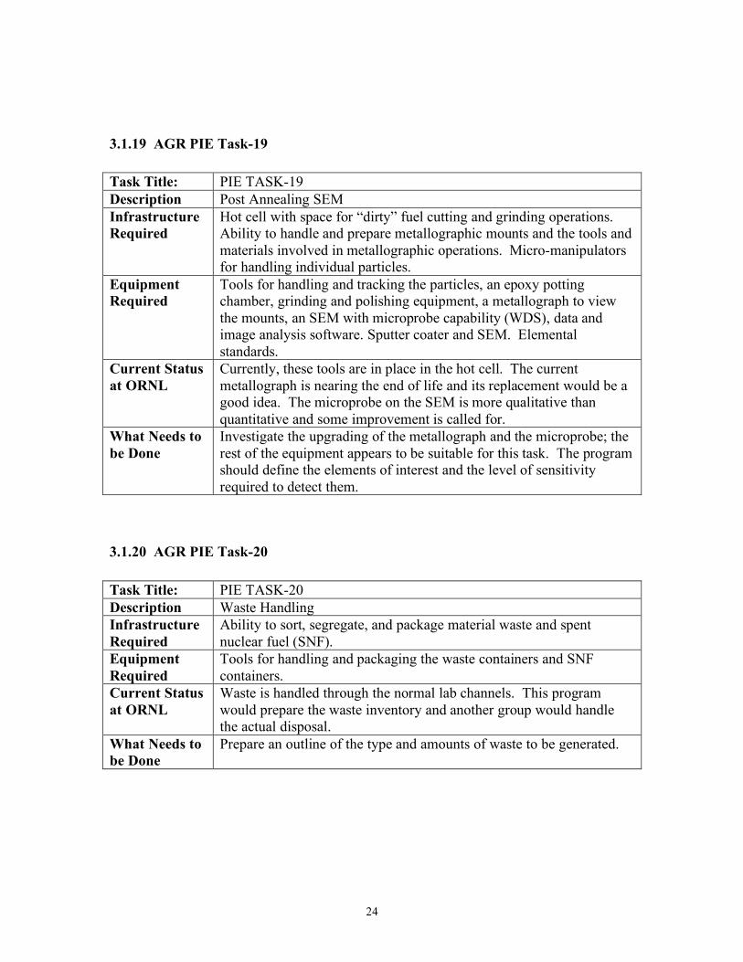
3.1.15 AGR PIE Task-15 Task Title: PIE TASK-15 Description Measure properties (thermal, physical, mechanical) on samples of
irradiated PyC, SiC, graphite, and metals. Infrastructure Required
A hot cell or hood, specialized testing equipment, sampling handling tools, analysis capability
Equipment Required
Testing jigs, testing equipment, specialized tools and methods. Much of this needs to be defined. Equipment at Buildings 3025E and 4508 could be used.
Current Status at ORNL
General testing equipment is in place; more details about the materials and methods are required to determine the actual apparatus required and the methods of preparation and analysis.
What Needs to be Done
Better define the needs, materials, and testing. These definitions need to be done early in the process as this type of equipment is expensive and complex to install in the hot cell. One also has to know the type of specimens required so that irradiation tests can be properly constructed and specimens machined. Determine whether the specific testing can be performed using the existing equipment in the LAMDA facility or Building 3025E.
3.1.16 AGR PIE Task-16 Task Title: PIE TASK-16 Description Radionuclide Transport in Irradiated Specimens Infrastructure Required
A hot cell or hood, specialized sampling equipment, ability to collect small samples, dust collection, sampling handling tools, analysis capability, special considerations for handling contamination. Possible radiochemical lab.
Equipment Required
Special tools for preparing the analysis samples, testing jigs, testing equipment, specialized tools and methods for handling small amounts of materials. Cutting or material shaving apparatus; an advanced micro gamma scanner would be of interest. Gamma/beta spectrometer, data analysis software, modeling guidance.
Current Status at ORNL
General testing equipment is in place; more details about the materials and methods are required to determine the actual apparatus required and the methods of preparation and analysis.
What Needs to be Done
Better define the needs, materials, and testing. This task is likely to be affected by contamination; careful planning will be required to conduct this task as the destructive sampling can only be done once. This is likely to be a major effort with special equipment.

23
3.1.17 AGR PIE Task-17 Task Title: PIE TASK-17 Description Fission Product Release during Postirradiation Annealing Infrastructure Required
A hot cell prepared for the furnace, utility manifold, I/O lines, off gas handling and sampling, gamma analysis area. Cooling water and power supplies.
Equipment Required
Specialized annealing furnace, tools for preparing the analysis samples, sweep gas system, cold traps, gamma spectrometers, methods for handling the collected fission metals. Casks and shielded sample transfer methods.
Current Status at ORNL
An annealing furnace is operational for gas collection, but not for metals. Metals can be collected, but the collection surface cannot be changed during operation. The airlock system on the furnace needs to be improved and overhauled to return this function to operation. The current system only uses a Type C thermocouple; a pyrometer may be of interest. The current system can only work with an inert gas.
What Needs to be Done
Determine the upgrades to the furnace that are necessary to perform the desired tasks. Full helium operation can be restored with a moderate amount of effort; aggressive chemical atmospheres will require a major equipment redesign and extensive testing at significant cost.
3.1.18 AGR PIE Task-18 Task Title: PIE TASK-18 Description Post Annealing Metallography Infrastructure Required
Hot cell with space for “dirty” fuel cutting and grinding operations. Ability to handle metallographic mounts and the tools and materials involved in metallographic operations. Micro-manipulators for handling individual particles.
Equipment Required
Iso-met saw for cutting fuel compacts, tools for handling and tracking individual particles, an epoxy potting chamber, grinding and polishing equipment, and a metallograph to photograph the mounts under both regular and polarized light. Image analysis software.
Current Status at ORNL
Currently, these tools are in place in the hot cell. The current metallograph is nearing the end of life and its replacement would be a good idea. Several possible replacements have been investigated.
What Needs to be Done
Investigate the upgrading of the metallograph; the rest of the equipment appears to be suitable for this task. The micromanipulator tools should be investigated and repaired/upgraded as necessary.
24
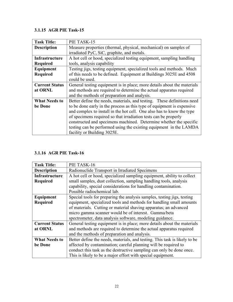
3.1.19 AGR PIE Task-19 Task Title: PIE TASK-19 Description Post Annealing SEM Infrastructure Required
Hot cell with space for “dirty” fuel cutting and grinding operations. Ability to handle and prepare metallographic mounts and the tools and materials involved in metallographic operations. Micro-manipulators for handling individual particles.
Equipment Required
Tools for handling and tracking the particles, an epoxy potting chamber, grinding and polishing equipment, a metallograph to view the mounts, an SEM with microprobe capability (WDS), data and image analysis software. Sputter coater and SEM. Elemental standards.
Current Status at ORNL
Currently, these tools are in place in the hot cell. The current metallograph is nearing the end of life and its replacement would be a good idea. The microprobe on the SEM is more qualitative than quantitative and some improvement is called for.
What Needs to be Done
Investigate the upgrading of the metallograph and the microprobe; the rest of the equipment appears to be suitable for this task. The program should define the elements of interest and the level of sensitivity required to detect them.
3.1.20 AGR PIE Task-20 Task Title: PIE TASK-20 Description Waste Handling Infrastructure Required
Ability to sort, segregate, and package material waste and spent nuclear fuel (SNF).
Equipment Required
Tools for handling and packaging the waste containers and SNF containers.
Current Status at ORNL
Waste is handled through the normal lab channels. This program would prepare the waste inventory and another group would handle the actual disposal.
What Needs to be Done
Prepare an outline of the type and amounts of waste to be generated.

25
3.1.21 AGR PIE Task-21 Task Title: PIE TASK-21 Description Reporting Infrastructure Required
General nuclear engineering and office support.
Equipment Required
No special equipment required.
Current Status at ORNL
Experienced staff available.
What Needs to be Done
Integrate the PIE task into the AGR program document handling structure.
3.2 GENERAL FUNCTIONAL REQUIREMENTS Table 1 is a listing of the general functional requirements of the activities likely to be required by the PIE activity and may be more useful for general program considerations than the previous task-by-task breakdown. As a general comment, one should note that there is not a one-to-one correspondence between the previously listed tasks, the general requirements, and the DTM. For the purposes of program management, the DTM may be of the most value because it is organized along the lines of specific program data needs and observations. This would allow the cognizant manager to see what is required to fulfill a need along with the tools and tasks required. It also folds in the issue of measurement uncertainty so the overall usefulness of the collected data can be assessed and the program can avoid spending time and resources on measurements that offer little value to the program goals.

26
Table 1. Functional Breakdown of the PIE Tasks
No. Task/Item Significance Comments 0 Environment, Safety,
and Health Need to make sure the project meets the laboratory and facility overall requirements and can be supported by the existing infrastructure.
Need to check Building Safety Analysis Review (SAR), criticality safety, and NEPA. Need to make sure waste streams and spent nuclear fuel can be handled. Proposed tasks must be within the operational envelope of the facility.
1 Shipping Irradiation capsules and/or components will have to be shipped to ORNL from INL. Shipping large items such as a full capsule would require a cask with a cavity approximately 4-5’ long. The availability of the necessary casks and their cost is a major issue as well as the cask license conditions.
If only pieces and parts are to be shipped to ORNL, small easier to handle casks could be used and the shipping is less of an issue. If a large cask is needed, the costs could be substantial and scheduling could be an issue. In addition, any modification of the cask CoC would require $100K plus and several months. An early start on this issue to resolve possible bottlenecks is important.
2 Facility cask handling Large casks may require large cranes and special handling or components to mate to specific hot cell ports. This is less of an issue for the smaller casks.
If a large and heavy cask is required for shipment of the full length test train, the facilities may have to be modified to accept the cask. This may include cranes, mating components, rigging, and supports. In addition the facility safety basis may have to be modified. An early start on this issue to resolve possible bottlenecks is important.

27
No. Task/Item Significance Comments 3 In-cell capsule or test
train handling and machine tools for opening
If the requirement is to handle a full length test train, the appropriate in-cell lifting and handling tools will have to be developed. Opening either a full or partial capsule will require machine tools. If the task only involves items of interest such as fuel and graphite bodies, only a modest amount of handling hardware will be required.
Handling and opening a full length test train will require a large jig of some kind that can hold and rotate the capsule as well as cut it. Even part of a capsule will require a significant jig. This will be a nontrivial development effort. Also, HTGR capsules generally contain a lot of 60Co which is difficult to shield and a fair amount of irradiated scrap will have to be disposed of.
4 Contamination issues Some of the fission product transport capsules may require analysis of small volumes of graphite millings. Avoidance of contamination by hot cell dust is important. Compacts that are to be tested in an annealing furnace for releases cannot be contaminated with cell dust prior to the testing. In either case, even small amounts of contamination will impact the results.
Special consideration will have to be given to the analysis of small graphite samples both from the contamination viewpoint as well as the background radiation level. It may be worthwhile to develop a special work space for this task. Also, this material may have to be removed from the hot cell and transferred to a dedicated gamma spectrometer.
5 Gamma scanning (in and out of cell)
Capsules and components are often gamma scanned to determine the internal state of the item. The size and activity of the item determine the bed size of the scanner and the necessary detector hardware. Low activity items may require long scan times. Complex items may require special methods to interpret the results or even new methods for collecting the data.
The gamma scanner is a fairly complex piece of equipment and changes to existing hardware would be expensive and time consuming. Options would be to do partial disassembly if the item did not fit on the scanner. The resolution of the scan may be limited by the activity of the item and the size of the item. Also, thought must be given to how the “image” is to be evaluated for this complex test train.

28
No. Task/Item Significance Comments 6 Component
Metrology Components are visually and dimensionally examined for changes. Usually custom jigs and fixtures are required for this work. The task may be automated or done manually. Equipment will need to be developed for the measurement task and macro photography will be required as well. Low to moderate resolution measurements could be done by photo imaging.
The best way to conduct this task is to measure the components in a manner that is consistent with the pre-irradiated inspection. Clear pictures may be difficult to get under hot cell conditions. The camera may be located outside of the hot cell or inside. Radiation damage to the camera is a major problem. Difficulties may arise if the fuel compacts are friable or the graphite fuel bodies crack.
7 Metallography Compact and individual fuel particle cross sections are used to assess the performance of the fuel and matrix material. Metal components may be examined as well.
Metallography involves cutting the fuel, potting the cut piece in an epoxy mount, and polishing the surface. The surface may also be etched. The complete mount is then viewed under a shielded microscope and usually photographed. This process is somewhat of an art and practice may be required for specific items. Irradiation generally changes the polishing properties of the materials.
8 Re-activation of fuel compacts and particles
In order to measure the short lived isotopes during accident testing the fuel must undergo a short irradiation. It can also be used to sort compacts.
Selected fuel can be irradiated in a TRIGA reactor, most likely in a KING furnace. Other options include the HFIR reactor and a possible 129I technique that does not require reactivation (needs further investigation). Releases may be measured during this re-irradiation and then during the subsequent accident testing. These techniques and equipment will be investigated at ORNL.
29
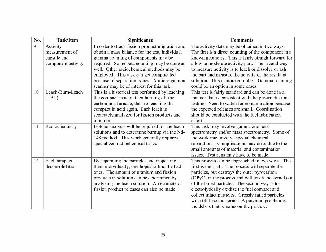
No. Task/Item Significance Comments 9 Activity
measurement of capsule and component activity
In order to track fission product migration and obtain a mass balance for the test, individual gamma counting of components may be required. Some beta counting may be done as well. Other radiochemical methods may be employed. This task can get complicated because of separation issues. A micro gamma scanner may be of interest for this task.
The activity data may be obtained in two ways. The first is a direct counting of the component in a known geometry. This is fairly straightforward for a low to moderate activity part. The second way to measure activity is to leach or dissolve or ash the part and measure the activity of the resultant solution. This is more complex. Gamma scanning could be an option in some cases.
10 Leach-Burn-Leach (LBL)
This is a historical test performed by leaching the compact in acid, then burning off the carbon in a furnace, then re-leaching the compact in acid again. Each leach is separately analyzed for fission products and uranium.
This test is fairly standard and can be done in a manner that is consistent with the pre-irradiation testing. Need to watch for contamination because the expected releases are small. Coordination should be conducted with the fuel fabrication effort.
11 Radiochemistry Isotope analysis will be required for the leach solutions and to determine burnup via the Nd-148 method. This work generally requires specialized radiochemical tasks.
This task may involve gamma and beta spectrometry and/or mass spectrometry. Some of the work may involve special chemical separations. Complications may arise due to the small amounts of material and contamination issues. Test runs may have to be made.
12 Fuel compact deconsolidation
By separating the particles and inspecting them individually, one hopes to find the bad ones. The amount of uranium and fission products in solution can be determined by analyzing the leach solution. An estimate of fission product releases can also be made.
This process can be approached in two ways. The first is the LBL. The process will separate the particles, but destroys the outer pyrocarbon (OPyC) in the process and will leach the kernel out of the failed particles. The second way is to electrolytically oxidize the fuel compact and collect intact particles. Grossly failed particles will still lose the kernel. A potential problem is the debris that remains on the particle.

30
No. Task/Item Significance Comments 13 IMGA By individually measuring key fission product
gamma emitters one can identify particles that have released fission products. Large numbers of particles need to be analyzed to find the small number of failures. This is a delicate task as the particles are easily broken. Segregation of the bad particles is important for later analysis.
This task requires a very specialized instrument – the Irradiated Microsphere Gamma Analyzer. Present equipment is in need of an upgrade and serious consideration should be given to this device to update and optimize the design. This is not a simple design task.
14 SEM/Microprobe Mount and polish selected particles. Examine particles with scanning electron microscope and microprobe. Determine microstructure and elemental composition.
This task requires an SEM capable of handling radioactive material. Typically, one does both gross images of the particle as well as scans of the kernel and coatings for the distribution of fission products. The sensitivity and qualitative nature of the device is important for detailed elemental analysis.
15 Fission gas and CO/CO2 particle content
Particle pressure is a failure driver and various means have been invented to control it. Experimental verification of the pressure would allow comparison between theory and experiment.
This device will have to be designed and tested. Because of the very small volumes involved, it is a design challenge. One should consult the fuel theory group to make sure the proper parameters are being measured.
16 Properties of irradiated materials
Mechanical properties are of major interest to this program. Items of interest are: strength, creep, and thermal properties.
This task will require some rather specialized equipment to prepare specimens and test them. More definition is required for this task. Long lead times may be required as installing this equipment in a hood or hot cell is complex.
17 Micro manipulators Small parts, especially particles will require special tools to handle and store.
Usually an array of motorized stages and vacuum tweezers are used to move particles and small components around. The challenge is integrate this equipment into the hot cell.

31
No. Task/Item Significance Comments 18 Annealing furnace Safety and accident testing requires that the
fuel be exposed to high temperatures and monitored for fission product releases. Generally one wants both gaseous and metallic releases as a function of time at temperature. Both inert and oxidizing atmospheres are of interest.
This task involves a complex furnace with provision for monitoring fission product release during operation. This task encounters some rather severe materials problems as well as some complex operational issues. The system must also be reliable for long (>1000 hours) periods of time.
19 Waste handling Task cleanup work. The program must supply the expected waste volumes and isotope inventories.
Waste handling facilities are a part of the operation of the building, but many details have to be addressed for the task to be cost effective and timely.
32
4.0 SPECIFIC TASK EQUIPMENT SPECIFICATION AND CURRENT STATUS At the present time, it appears the AGR PIE task will require a major equipment development task since much of the past equipment has been discarded or needs to be upgraded. Also, greater throughput and labor efficiency are needed to control costs and meet an aggressive schedule. The following sections detail some options for the program to consider. One major issue for management to consider is the degree of coordination between sites. It may be worthwhile to standardize some or much of the PIE equipment so that there are cost savings and consistency between sites. This may help in later analysis and avoid measurement artifacts that complicate interpretation of the results. Another alternative is to focus one site on the particularly complex tasks to avoid duplication of expensive equipment. That site staff could also concentration on a narrower selection of tasks. A final consideration is that any new equipment that is developed should be designed with an eye toward future use and/or flexibility. While the specific nature of this work often precludes flexibility for future changes, some effort and thought should be expended in this direction owing to the cost of this equipment and disposal issues.
4.1 TEST TRAIN GAMMA SCANNING The size and internal complexity of the test train may make gamma scanning the test train difficult. The many tubes, thermocouples, and three dimensional structure of the test train complicate imaging; a simple projection may be difficult to understand. Some thought will have to be given to what information is desired and how that information can be obtained from a gamma scan. If the capsule can be rotated on the gamma scanner along its axis, it may be possible to do tomographic reconstruction; otherwise the internal structure projected upon itself may make interpretation difficult because of the complex construction of the AGR capsule test train. A one dimensional gamma scan may not be of much value. To move forward with this task one needs to:
1. Determine what information is required by the program. 2. Determine if the existing equipment can handle this item and what modifications
to the equipment and software might be required. 3. Decide if the capsule should be scanned whole or cut into pieces. 4. Determine what to do with the data and how to present it in a programmatically
useful way. 5. Decide if this information is cost effective and whether the program could
proceed ahead without it. It is possible that the gamma scanner might require a complete redesign to obtain a useful imaging of the internal structure of the test train because of its complexity. If so, the

33
program should decide if the information to be obtained is worth the cost. Other diagnostic techniques may be more cost effective if only limited data is needed. For example, the sweep gas flow rates and pressures along with the R/B data could be used to decide if the capsule operation went well. The current configuration can be used with minimal changes (mostly a mount modification) to 2D scan a single capsule; however, if the entire test train must be scanned in total prior to disassembly, then the gamma scanner will require a great deal of modification. Piecewise scanning may be possible, but the test train may simply be too large. Table 2 is a rough estimate of the costs involved in a major modification of the scanner. This is only a very rough estimate and more detail would be required if a decision is made to proceed.
Table 2. Order of Magnitude Gamma Scanner Cost Evaluation For Full Train Scanning (Hot Cell Time Not Included)
Task Staff
Months Materials
($K) Total ($K)
Determine Existing Task Suitability 0.5 15 Redesign 3 90 Fabrication 1 50 80 Software development 2 60 Testing and Installation 1 15 45 Order of Magnitude Estimate 290
4.2 TEST TRAIN DISASSEMBLY AND COMPONENT REMOVAL The size and the intricate design of this unit appear to demand that a special purpose disassembly jig needs to be designed for its opening. A first cut at the design needs seems to indicate that:
1. The jig will be several feet long. 2. It will have to allow for the rotation of the capsule train. 3. Precision cutting will be necessary, possibly using an abrasive cutoff wheel. 4. A separate disassembly jig may be required for the individual capsules. 5. The tight tolerances may demand special deburring of cut pieces to insure
components can be slid apart. Hopefully, longitudinal slitting will not be required. 6. The large amount of irradiated metal (60Co) will probably have a higher and more
challenging radiation dose than the fuel. 7. Steps will have to be taken to segregate this metal to avoid exposing the hot cell
equipment to a continuous high radiation dose. 8. Visual inspection and disassembly operations may require the use of an in-cell
camera. The high radiation levels associated with the irradiated capsule metal may limit the lifetime of the camera and optics.

34
9. Contamination of some fuel compacts and components may be an issue. The fuel to be tested in the annealing furnace and the graphite diffusion specimens must not pick up any cell or disassembly contamination. Fission product pickup will complicate the annealing tests and graphite measurements and capsule metal contamination could damage the fuel SiC at high temperatures.
This equipment will require a serious design effort, even if some of the in-cell tooling can be reused. Table 3 is a rough estimate of the costs involved in developing such an apparatus. It may be possible to modify some existing equipment; in this case the cost may be significantly lower. Overall, this could be a large piece of equipment with one or more cutting axes and more than one cutting tool. An additional push-out fixture may be required.
Table 3. Order of Magnitude Disassembly Jig Cost Evaluation (Hot Cell Time Not Included)
Task Staff
Months Materials
($K) Total ($K)
Determine Needs 0.5 15 Design 3 90 Fabrication 1 100 130 Testing and Installation 2 15 75 Order of Magnitude Estimate 310
4.3 METROLOGY Past metrology work for fuel compacts and graphite bodies was largely done by hand with V-Blocks and dial indicators [2]. This is slow and tedious work; more automation is certainly desired for the program, especially if a large number of specimens will be examined. The program should tally up the work load, the measurements per specimen and the required accuracy to get an estimate of the work load. With this in mind, measurement jigs should be designed using some contemporary measurement tools that have a track record of hot cell use. Items to consider:
1. It may be possible to measure compacts using laser micrometers or other non-contact methods. This would speed the process up as long as the compacts have good measurement surfaces. The compacts made from overcoated particles have a smoother surface than the injection made compacts, so surface roughness and friability are less of an issue.
2. Better use of computers and databases could allow rapid collection, analysis and dissemination of the data. A small task to investigate this would be of value.
3. A correspondence between the modeling and the PIE task needs to be established so the dimensions of interest can be measured. This would also allow a data collection optimization study to be conducted so that high value measurements are taken.
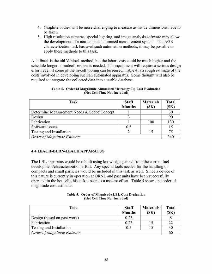
35
4. Graphite bodies will be more challenging to measure as inside dimensions have to be taken.
5. High resolution cameras, special lighting, and image analysis software may allow the development of a non-contact automated measurement system. The AGR characterization task has used such automation methods; it may be possible to apply these methods to this task.
A fallback is the old V-block method, but the labor costs could be much higher and the schedule longer; a tradeoff review is needed. This equipment will require a serious design effort, even if some of the in-cell tooling can be reused. Table 4 is a rough estimate of the costs involved in developing such an automated apparatus. Some thought will also be required to integrate the collected data into a usable database.
Table 4. Order of Magnitude Automated Metrology Jig Cost Evaluation (Hot Cell Time Not Included)
Task Staff
Months Materials
($K) Total ($K)
Determine Measurement Needs & Scope Concept 1 30 Design 3 90 Fabrication 1 100 130 Software issues 0.5 15 Testing and Installation 2 15 75 Order of Magnitude Estimate 340
4.4 LEACH-BURN-LEACH APPARATUS The LBL apparatus would be rebuilt using knowledge gained from the current fuel development/characterization effort. Any special tools needed for the handling of compacts and small particles would be included in this task as well. Since a device of this nature is currently in operation at ORNL and past units have been successfully operated in the hot cell, this task is seen as a modest effort. Table 5 shows the order of magnitude cost estimate.
Table 5. Order of Magnitude LBL Cost Evaluation (Hot Cell Time Not Included)
Task Staff
Months Materials
($K) Total ($K)
Design (based on past work) 0.25 8 Fabrication 0.25 15 22 Testing and Installation 0.5 15 30 Order of Magnitude Estimate 60

36
4.5 IRRADIATED MICROSPHERE GAMMA ANALYZER (IMGA) The IMGA unit is a very specialized device for handling and determining the isotopic inventory of individual coated particle fuel [3]. While useful, the device needs to be updated to meet the program goals. It works best with particles that are somewhat larger than the AGR particles; the smaller particles can be damaged as they cycle through the device. In addition, the current system relies on obsolete computer hardware and is difficult to repair. Finally, the compact deconsolidation process can leave a small amount of debris on the particle which can interfere with the proper operation of the unit. The first order of business would be to determine the programmatic needs for individual particle examination. As was noted in a previous section, this can be an expensive and time consuming part of the PIE and a clear definition of the task is needed to make effective use of the unit and the collected data. If a large amount of data is to be collected, several units may have to be operated in parallel. The IMGA unit is, however, the only proven way to isolate individual failed fuel particles. Before proceeding with the concept for a new IMGA type device, the documentation for the old unit should be reviewed so one understands the historical design and purpose. One may also want to review some pneumatic methods for handling particles; great leaps in technology have taken place since the design of this unit. Major lessons learned with this device are that any new design must:
1. Be able to handle particles of several sizes, not only because of different fuel types, but also to be able to handle outliers within a fuel type.
2. The device must be able to deal with seriously out-of-round particles and particles with bits of matrix material attached to them.
3. The device must be able to handle broken particles and particle debris. It needs to be smart enough to reject debris and not get hung up. It also must not break particles.
4. It should be reasonably easy to maintain under hot cell conditions. Simple and reliable operation is more important than flexibility at the price of reliability.
5. It must have a simple loading and unloading method. The program will need an early start on this complex device. Table 6 is a rough estimate of the costs involved in developing such an apparatus; some experimentation may be required and time should be allowed for this. Some thought will also be required to integrate this unit into a useable database so the data is easily and quickly available to the program staff for evaluation.

37
Table 6. Order of Magnitude IMGA Cost Evaluation (Hot Cell Time Not Included)
Task Staff Months
Materials ($K)
Total ($K)
Determine Measurement Needs & Scope Concept 1 30 Design 12 20 380 Fabrication 6 100 280 Particle Micro-manipulator Design 3 90 Particle Micro-manipulator Fabrication 3 25 115 Software Issues 3 10 100 Testing and Installation 3 30 120 Order of Magnitude Estimate 1115 A less costly option is also possible for the IMGA upgrade, assuming that the basic system is acceptable. Rather than do a complete upgrade, this plan would replace the singulizer with a pneumatic motor slide system to replace the current mechanical hopper feed system. An update of the control system would also be necessary; the balance of the IMGA unit would remain the same. This partial upgrade option is shown in Table 7.
Table 7. Order of Magnitude Partial IMGA Cost Evaluation (Hot Cell Time Not Included)
Task Staff Months
Materials ($K)
Total ($K)
New Singulizer Design 2 60 Fabrication 0.25 125 130 Control System 1 10 40 Software Issues 1 30 Testing and Installation 1 10 40 Order of Magnitude Estimate 300
4.6 METALLOGRAPHIC EXAMINATION A large segment of the metallographic preparation equipment is in good operating condition at Building 3525. A weakness is the metallograph itself; it is an old unit and the internal parts have considerable wear and backlash, making specimen handling and focusing tedious. It is not automated so that photo mosaics have to be assembled in a time consuming manner by hand. Replacement of this unit by one that is automated and easier to use would result in better quality photographs at a lower labor cost. In addition, the optics could be better tailored to current needs. The AGR fuel characterization group has considerable experience in this type of work along with its automation, so the program already has a resource to tap.

38
Table 8 is a rough estimate of the costs involved in replacing the metallograph. Some thought will also be required to integrate the collected images into a useable database so the photos can be easily stored and made available to the program staff.
Table 8. Order of Magnitude Metallograph Replacement Cost Evaluation (Hot Cell Time Not Included)
Task Staff
Months Materials
($K) Total ($K)
Location Layout 0.5 15 Layout Design 1 30 Metallograph & Support Parts 1 120 150 Software issues 1 30 Testing and Installation 1 15 45 Order of Magnitude Estimate 270
4.7 SEM/MICROPROBE The current SEM/Microprobe is an unshielded unit located near the preparation cell. This is an 80’s vintage design whose microprobe capabilities are more qualitative than may be desired for this program. It is probably not cost effective to upgrade this device. A replacement would consist of purchasing a new unit at a cost of several hundred thousand dollars. Another option is to upgrade another SEM/microbe presently under procurement by another program. This SEM will be used in the CCCTF cubicle and has the potential to be upgraded to have microprobe capability. One downside to this option is that the device will have to be operated in a batch mode as the CCCTF cubicle must be shared by other projects. An advantage is that higher radiation levels could be tolerated. Table 9 is a rough estimate of the costs involved in updating the SEM/Microprobe to one that is more sensitive. The fallback position is to use the current unit; however, upgrading offers the advantage of one unit for throughput and another unit for more quantitative work or for work with higher radiation levels. Table 9. Order of Magnitude Second SEM Upgrade Cost Evaluation (Hot Cell Time Not Included)
Task Staff Months
Materials ($K)
Total ($K)
New Spectrometers & Software 0.5 200 215 Specimen Handling Concept in CCCTF Cell 0.5 15 Support Parts 0.5 20 35 Testing and Installation 1 15 45 Order of Magnitude Estimate 310
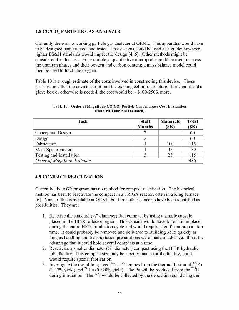
39
4.8 CO/CO2 PARTICLE GAS ANALYZER Currently there is no working particle gas analyzer at ORNL. This apparatus would have to be designed, constructed, and tested. Past designs could be used as a guide; however, tighter ES&H standards would impact the design [4, 5]. Other methods might be considered for this task. For example, a quantitative microprobe could be used to assess the uranium phases and their oxygen and carbon content; a mass balance model could then be used to track the oxygen. Table 10 is a rough estimate of the costs involved in constructing this device. These costs assume that the device can fit into the existing cell infrastructure. If it cannot and a glove box or otherwise is needed, the cost would be ~ $100-250K more.
Table 10. Order of Magnitude CO/CO2 Particle Gas Analyzer Cost Evaluation (Hot Cell Time Not Included)
Task Staff
Months Materials
($K) Total ($K)
Conceptual Design 2 60 Design 2 60 Fabrication 1 100 115 Mass Spectrometer 1 100 130 Testing and Installation 3 25 115 Order of Magnitude Estimate 480
4.9 COMPACT REACTIVATION Currently, the AGR program has no method for compact reactivation. The historical method has been to reactivate the compact in a TRIGA reactor, often in a King furnace [6]. None of this is available at ORNL, but three other concepts have been identified as possibilities. They are:
1. Reactive the standard (½” diameter) fuel compact by using a simple capsule placed in the HFIR reflector region. This capsule would have to remain in place during the entire HFIR irradiation cycle and would require significant preparation time. It could probably be removed and delivered to Building 3525 quickly as long as handling and transportation preparations were made in advance. It has the advantage that it could hold several compacts at a time.
2. Reactivate a smaller diameter (¼” diameter) compact using the HFIR hydraulic tube facility. This compact size may be a better match for the facility, but it would require special fabrication.
3. Investigate the use of long lived 129I. 129I comes from the thermal fission of 239Pu (1.37% yield) and 241Pu (0.820% yield). The Pu will be produced from the 238U during irradiation. The 129I would be collected by the deposition cup during the

40
heating test and then it can be leached off for analysis. The solution would then undergo chemical separations to isolate the iodine. This segregated solution could either then be analyzed for 129I directly or could undergo neutron activation to generate 130I, which would then be counted.
These concepts are still being investigated and it is not clear what the best approach will be. Concepts 1 and 2 would likely require significant infrastructure at Building 3525 to load, weld, and open the capsules. Concept #3 is attractive because of its limited reactor need; however, considerable effort is required to determine if it is feasible. Because of the uncertainties, Table 11 reflects the concept evaluations rather than the equipment costs. Once a credible option and its supporting details are identified, specific costing can be computed.
Table 11. Order Of Magnitude Reactivation Concept Cost Evaluation
Task Staff
Months Materials
($K) Total ($K)
129I Conceptual Evaluation 1 30 Re-activation Concept 2 60 Transportation and Cask Issues 0.5 15 Order of Magnitude Estimate 105 If the re-activation in HFIR is selected, the first of kind re-activation rig would most likely cost ~ $100K to $1000K; the use of 129I would probably involve roughly ~ $50K to $250K. These numbers have a high uncertainty and the results of the concept planning are necessary before better estimates can be made.
4.10 ANNEALING FURNACE The current annealing furnace at ORNL is capable of operation with a helium atmosphere and a variety of temperature ramps [7-9]. It presently cannot change deposition surfaces (cups) during operation because of an inoperable airlock; only gas release can be continuously monitored. To return it to its full operational status would require the redesign of the upper airlock along with the addition of some cooling lines. Table 12 shows the estimated cost breakdown.
Table 12. Order of Magnitude Airlock Annealing Furnace Cost Evaluation (Hot Cell Time Not Included)
Task Staff
Months Materials
($K) Total ($K)
Design/Upgrade 2 60 Fabrication 60 60 Testing and Installation 1 10 40 Order of Magnitude Estimate 160

41
This configuration cannot handle oxidizing atmospheres and substantial design changes would be required for it to do so. It is not clear whether the current fission production collection systems could be kept or not; in any event, a major design effort would be required to develop a furnace that would function over the desired temperature range in an oxidizing atmosphere. A large amount of testing and redesign would likely be required; past German designs may be used as a starting point [10]. A quartz tube with radiant heating may be another option to consider. The program needs to plan for lengthy R&D effort. Table 13 is a rough estimate of the costs involved in testing, designing and constructing the oxidizing atmosphere version of this device.
Table 13. Order of Magnitude Oxidizing Annealing Furnace Cost Evaluation (Hot Cell Time Not Included)
Task Staff
Months Materials
($K) Total ($K)
Conceptual Design of Oxidizing Version 3 10 100 Design 12 20 380 Fabrication 3 250 340 Gas Analysis 3 50 140 ES&H Issues 1 30 Testing and Installation 6 150 330 Order of Magnitude Estimate 1320
4.11 GRAPHITE SORPTIVITY/DIFFUSION DATA COLLECTION Experiments involving the analysis of fission product transport often require the determination of the both the total inventory of a specific fission product as well as the spatial profile within a graphite component. Determining spatial profiles can be difficult and time consuming, especially if specimen sectioning is required. Contamination from the hot cell is also a great concern. Over the past decade advances have been made in detectors, apertures, and computing so the program should consider the development of a micro-scale tomographic gamma scanner. Such units have been developed by the medical community for the scanning of small animals; application of this technology to the scanning of similar sized capsule components appears to be feasible and offers a great productivity increase over the “slice and dice approach” [11]. A modular unit could be designed for use in the CCCTF cubicle and, by keeping it relatively free from contamination, hands-on maintenance would be possible. Table 14 is a rough estimate of the costs involved in constructing this device. These costs assume that the device can fit into the existing cell infrastructure.

42
Table 14. Order of Magnitude Micro-Gamma Scanner Cost Evaluation
(Hot Cell Time Not Included)
Task Staff Months
Materials ($K)
Total ($K)
Conceptual Design of Scanner 1 30 Design 3 30 120 Fabrication 3 100 190 Testing and Installation 3 20 110 Order of Magnitude Estimate 450
4.12 MATERIAL PROPERTIES TOOLS The material modeling codes require information about thermal and mechanical properties of the fuel compacts, matrix material, graphite, and fuel. These properties have not yet been described in enough detail so that the PIE task can be scoped out. Items involving low activity materials can likely be measured at the LAMDA facility and the costs involved in moving specimens from Building 3525 to Building 4508 can be minimized. If the equipment can be used without special modification, the only costs to be incurred would be the development of the unique fixtures required and perhaps some safety documentation. Higher level non-fuel materials might be tested at Building 3025E if the alpha contamination can be held to a low level. In this case, advantage can be taken of the already in place materials testing equipment. If fuel must be tested, the specialized equipment must be installed at Building 3525, perhaps in the CCCTF cubicle. The purchase and installation of this equipment will be a substantial cost. A rough guide is $150-250K per piece of equipment.
4.13 HOT CELL RESOURCES The installation and testing of the above equipment will require a considerable allocation of hot cell resources. Table 15 is an order of magnitude estimate for this need.

43
Table 15. Order of Magnitude Hot Cell Time Costs.
Task Cell Days Materials
($K) Total ($K)
Gamma Scanner 10 50 Disassembly Apparatus/Jig 10 50 Metrology Apparatus 10 50 LBL 5 25 IMGA 10 15 65 Metallograph 10 15 65 SEM Upgrade 5 25 PGA 10 50 Helium Furnace Airlock Repair 5 25 Oxidizing Furnace Concept 20 100 Micro-gamma scanner 5 25 Material Testing Tools/Apparatus 10 50 Other Services (ES&H, criticality) 25 25 Order of Magnitude Estimate 605
4.14 EQUIPMENT STANDARDIZATION It is likely that a considerable amount of new equipment will be required for the AGR PIE task. Since this equipment may be required at both ORNL and INL, a common design effort can be of great value to avoid duplication of effect and to pool the resources of both sites so that the best design options may be developed. While site differences can impose constraints on coordination, this should not be construed as an insurmountable obstacle. In additional to equipment development, a common data format or database should be considered as well. Perhaps this could be modeled on other experimental programs. A lot of gas cooled reactor historical data is difficult to obtain and one goal of this effort should be easy access to generated data. During the course of the PIE evaluation task, some thought should be given to what tasks would be candidates for multiple site development and how the necessary equipment can be developed. In particular:
1. The program should identify the PIE tasks and the manner to conduct them as well as issues associated with throughput. The need for large amounts of data or for tasks that take a long time would be drivers for multi-site efforts.
2. Relevant site constraints should be identified so they can be taken into consideration during the design process.
3. The format for data storage should be part of the design effort so that data collection and sharing is not cumbersome.
4. Common operating procedures and analysis methods should be outlined to make sure the equipment is operated in a proper and consistent manner.

44
5. The program should consider not only resources at the sites for equipment development, but other outside resources as well so that robust state of the art designs can be produced.
Well developed common equipment designs can save the program a lot of time and money while producing consistent results across the DOE complex. A common design can also help with troubleshooting and avoid data artifacts due to different measurement methods and techniques.
5.0 PATH FORWARD The previous sections have detailed the current situation for AGR PIE work at the ORNL facilities. Some of the equipment to be developed will be expensive and will require extensive developmental work. Now is the time for the program to better define the PIE needs and the amount of work to be done so that PIE tasks can be solidly defined and the necessary equipment developed. One might proceed as follows:
1. Compile the results of the PIE capability tour so that the program has a reasonable idea of the current state of the PIE facilities and tools. This will provide a starting point for the program and will allow the program to take advantage of any special capability.
2. Complete or at least prepare a draft DTM so that the data to be collected, its required uncertainty, and collection apparatus can be linked to a specific program need or request. This is necessary to insure that the PIE tasks are coupled to specific program needs and whether the data is likely to resolve its generating issue. Specific thought should be given to the sensitivity of the computational models and the maximum acceptable level of uncertainty. One may also reflect on the value of single effects data versus integrated data. For this program, one also may wish to categorize the tasks as licensing related or engineering data since the demands of a licensing review are rather specific.
3. Determine the throughput required for the identified tasks. This will allow the PIE staff to make decisions as to the level of automation required and the workload required.
4. Decide on the specific PIE tasks to be conducted at the various sites. 5. Determine what the equipment needs are. First determine what existing
equipment can be used and identify any necessary modifications. Next, determine what equipment can be purchased and used with minimal modifications. Finally, identify the important equipment development efforts that this program will require. Once the equipment needs have been sorted out and the build/buy decisions made, a serious standardization effort between sites should be established to efficiently pursue this effort.
6. Develop and design the required equipment. Determine if the original data needs can be met or if modifications to the DTM are required because of equipment issues. Refine the technical and licensing approach so that it can be achieved with

45
what is practical from the PIE task. Purchase and install other equipment. Verify that the equipment works as desired and works in a hot cell.
7. Complete a dry run and satisfy the needs of the startup QC audit. Report to the program the status of the PIE preparations and any shortcomings that may impact the ability to collect the desired data.
As may be inferred, this sequence of events will be time consuming and expensive; an early start and rational set of data needs, along with proper funding will be required for a successful PIE. A more limited PIE preparation effort may be necessary if funding constraints prevent a comprehensive approach. Appendix B outlines a minimal preparation task that would allow the ORNL hot cells to support the early AGR PIE effort with a moderate throughput; fission product transport and extensive particle analysis tasks would be compromised however. During the course of this effort it is likely that some desired tasks will be difficult and expensive or even impossible to do with the necessary accuracy in the hot cell environment. In this case the program should review its options and decide if the program need can be satisfied in another way.
6.0 SUMMARY ORNL has facilities and experienced staff that can execute the AGR PIE task. While the current task needs to be more formally defined, the basic outline is clear and the existing capabilities can be assessed within the needs of the tasks defined in the program plan. Building 3525 is available for this task and has a history of coated particle PIE work. This building is equipped with the tools necessary for PIEs of this nature, but the long hiatus in coated particle fuel work has left it with out-of-date and end-of-life analysis tools. This report identified several of these tools and provided rough estimates of the cost to update and replace them. In addition, other ORNL buildings are available to support Building 3525 in specialized tasks along with the laboratory infrastructure. Before beginning any equipment development effort, the tasks should move to the next program step and be better defined so that the measurement uncertainties and throughput needs can be reviewed. A DTM should be prepared so that the program data needs can be compared against what is practical in the hot cell and to make sure nothing is overlooked. Next, the specific PIE plan needs to be written for the particular irradiation test. Finally, thought should be given to the development of standard design between sites to avoid redundant design efforts and different measurement techniques. This is a potentially cost saving effort that can also avoid data inconsistencies.
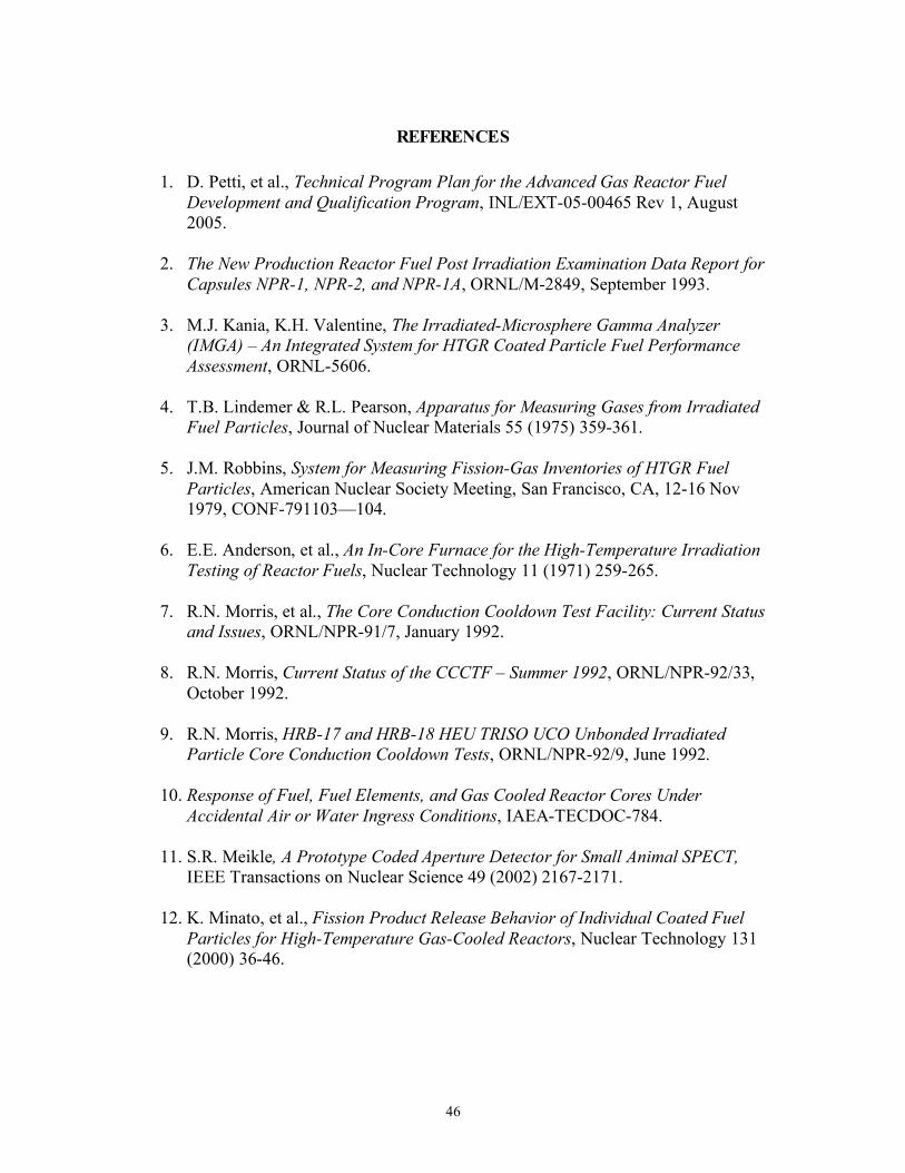
46
REFERENCES
1. D. Petti, et al., Technical Program Plan for the Advanced Gas Reactor Fuel Development and Qualification Program, INL/EXT-05-00465 Rev 1, August 2005.
2. The New Production Reactor Fuel Post Irradiation Examination Data Report for
Capsules NPR-1, NPR-2, and NPR-1A, ORNL/M-2849, September 1993.
3. M.J. Kania, K.H. Valentine, The Irradiated-Microsphere Gamma Analyzer (IMGA) – An Integrated System for HTGR Coated Particle Fuel Performance Assessment, ORNL-5606.
4. T.B. Lindemer & R.L. Pearson, Apparatus for Measuring Gases from Irradiated
Fuel Particles, Journal of Nuclear Materials 55 (1975) 359-361.
5. J.M. Robbins, System for Measuring Fission-Gas Inventories of HTGR Fuel Particles, American Nuclear Society Meeting, San Francisco, CA, 12-16 Nov 1979, CONF-791103—104.
6. E.E. Anderson, et al., An In-Core Furnace for the High-Temperature Irradiation
Testing of Reactor Fuels, Nuclear Technology 11 (1971) 259-265.
7. R.N. Morris, et al., The Core Conduction Cooldown Test Facility: Current Status and Issues, ORNL/NPR-91/7, January 1992.
8. R.N. Morris, Current Status of the CCCTF – Summer 1992, ORNL/NPR-92/33,
October 1992.
9. R.N. Morris, HRB-17 and HRB-18 HEU TRISO UCO Unbonded Irradiated Particle Core Conduction Cooldown Tests, ORNL/NPR-92/9, June 1992.
10. Response of Fuel, Fuel Elements, and Gas Cooled Reactor Cores Under
Accidental Air or Water Ingress Conditions, IAEA-TECDOC-784.
11. S.R. Meikle, A Prototype Coded Aperture Detector for Small Animal SPECT, IEEE Transactions on Nuclear Science 49 (2002) 2167-2171.
12. K. Minato, et al., Fission Product Release Behavior of Individual Coated Fuel
Particles for High-Temperature Gas-Cooled Reactors, Nuclear Technology 131 (2000) 36-46.

APPENDIX A

A-1
APPENDIX A. DATA TEST MATRIX Table A-1 is an example of a Data Test Matrix. It is a matching of a particular program data need to a PIE method and what can be expected from that method. The purpose of this matrix is to match each required program need to a PIE task and offer a realistic guide as to whether the need can be fulfilled. Management can then decide whether to proceed with the task, change or delete the task, or to accept a less than desired outcome. Note that there is not necessarily a one-to-one correspondence between program needs, PIE tasks, and PIE equipment. It may be worthwhile to review the needs and restructure the PIE tasks along the lines of the needs to give the program a better idea of what the task structure and equipment requirements are on an informational basis. In the past, the program often handled this task with Design Data Needs (DDNs) that helped inform management as to the impact a task may or may not have on the design of a reactor. However, for the specific needs of a PIE, it is more useful to connect the required data to a PIE method because of the great expense of PIE work and the special equipment required. A useful plan would be to use the DDNs to define the data to be collected and use the DTM to estimate the usefulness and practicality of collecting this data. One of the most important outcomes of this exercise is to determine if the data required for specific applications can really be collected by the PIE program. Computational models are often sensitive to particular input parameters and it may either be very difficult to make the required measurements or the number of measurements required may be very large. In cases like this, the above planning can help the program decide to either continue to pursue acquisition of the data or to develop an alternative approach to the problem. In principal, the DTM should be prepared before the experimental program is started so that the program has a model for the evaluation of the likely success of a particular experiment.

A-2
Table A-1 Data Test Matrix Example
Program Need Acceptable
Uncertainty PIE Method Likely Uncertainty Comments
Gamma Scan Resolution of internal parts to detect distortion, gaps, and relocation.
Gamma Scan capsule train, reconstruct image either by simple projection or more complex methods
Simple capsule layouts give good results with a projection; complex designs may be confusing and require a different approach.
Need to review approach to make sure this complex capsule can be imaged to the degree necessary to resolve the internal structure.
Compact Metrology Measure the compacts length and diameter (at several locations) to a precision that will allow detection of swelling/shrinking to within a modeling goal limit.
Measure the compacts using high accuracy contact or non-contact means to a similar accuracy of the pre-irradiated measurement.
Can probably measure the compacts to a degree that is comparable with the pre-irradiation measurement.
Need to determine what changes are predicted and double check to make sure the proper measurements are being taken, both in accuracy and in location.
Kernel and buffer behavior -Kernel extrusion -Kernel migration -Kernel phases for comparison with thermo-chemical predictions
Need to estimate kernel movement from center to within ~5% and determine if buffer cracked and kernel extruded into cracks. Determine phase segregation and carbon absorption into kernel.
Prepare and examine metallographic mounts; use image software to dimension kernel and measure cracks. Use SEM to examine kernel phases.
Probably can determine kernel migration to within 5%. SEM can at least provide qualitative information about phases.
Need to determine if the SEM elemental resolution is adequate for examining phases. Also, need to determine the number of particles to examine.

A-3
Program Need Acceptable Uncertainty
PIE Method Likely Uncertainty Comments
Distribution of fission products in the layers and any signs of corrosion to compare with transport and corrosion models.
Not clear; want to resolve corrosion issues and any damage to the SiC layer.
Metallographic sections followed by visual and SEM examination.
Can see gross damage and high transport, may have difficulties with low levels of fission products and grain boundary attack.
The spatial and elemental resolution of the SEM is a major factor in this type of analysis. This needs to be examined in detail prior to starting the task so that reasonable goals can be set.
Particles with damaged layers to compare with particle performance codes.
A resolution of less than one particle.
LBL for general purposes, metallographic mounts for some cases, deconsolidation and IMGA to look for individual failed particles. Reactivation can be used to sort out compacts.
Probably can get to the one particle limit. Locating the actual layer damage will be very difficult as one is unlikely to find it by using a metallographic mount. Advanced x-ray tomographic methods may be of interest.
LBL offers a fairly quick way to find the failed fraction, but finding the failed particle and what caused the failure will be much more difficult.
Fission product transport to support models and their development.
Overall, would like agreement within an order of magnitude.
Gamma counting of specimens, sectioning of specimens, leaching of specimens and counting. Micro gamma scanner technology may be applied here.
In a proper geometry, a counting accuracy of 5-10% is reasonable. Need to watch for contamination. It is not clear how the measurements work back to the models.
One also needs to know the source term to compute the absolute transport. May have to leach the fuel compact to estimate the released fraction. Tomographic reconstruction methods may be of value here.

A-4
Program Need Acceptable Uncertainty
PIE Method Likely Uncertainty Comments
Fission gas and particle CO/CO2 content for thermo-chemical modeling.
Not sure, need to be able to resolve pressures less than a few atmospheres.
Use the PGA to measure the particle gases and determine their composition.
This would depend on the apparatus. Past designs seem to have worked to an acceptable accuracy.
May also be able to determine the fission gas release fraction. What temperatures are of interest?
Coating material properties for use by particle modeling code.
Unknown. This needs to be determined.
At present, properties are to be inferred from fuel performance.
Probably high. This issue needs to be examined.
This area has not been scoped out much.
Accident testing under inert conditions to supply data for the release codes.
Within a factor of 2? Use CCCTF type annealing furnace to expose specimens to high temperatures and collect the released fission products.
Past testing has had good overall mass balances, but this is temperature sensitive. Will need to double check this.
The basic operation of the inert furnace is understood, some details remain, but they are not considered major.
Accident testing under oxidizing conditions to supply data for the release codes.
Within a factor of 2? Use modified CCCTF type annealing furnace to expose specimens to high temperatures along with an oxidizing atmosphere and collect the released fission products.
This is a research topic. Probably can reach a factor of two, but needs to be confirmed by testing.
This equipment will have to be developed -and tested.

B-1
APPENDIX B

B-1
APPENDIX B. MINIMAL AGR PIE PREPARATION
1.0 General In the interests of conserving resources a minimal ORNL PIE preparation task can be planned with the following constraints: 1) ORNL receives only individual capsules or fuel compacts and only minimal
segmenting is required to open the capsules and remove the components; 2) The jigs and fixtures are designed only for the Leach/Burn/Leach task (LBL),
individual capsule opening, compact handling, and the high temperature annealing in helium;
3) Existing low throughput metrology equipment is used with minimal adjustments for fuel compact measurements;
4) ORNL only performs the following PIE tasks: i) Minor individual capsule disassembly; ii) Compact dimensional measurements, mass, and immersion density (as
acceptable); iii) Leach/Burn/Leach and fuel compact deconsolidation; iv) IMGA analysis of the deconsolidated particles; v) CCCTF heating of the compacts and individual particles in a helium
atmosphere; vi) Metallographic mount preparation of the compacts and individual particles; vii) SEM/Microprobe examination of the compact sections and individual
particles. Under this minimal plan, the following equipment would be upgraded: 1) Metallograph; 2) CCCTF furnace; 3) IMGA; 4) Jigs and fixtures for LBL, individual capsule disassembly, and compact handling; 5) Minor fixture and procedure changes to existing hardware for compact dimensional,
mass, and immersion density measurements. The old metallograph would be replaced with a modern programmable unit, the airlock on the CCCTF furnace would be replaced restoring the time dependent metallic fission product collection in helium, and part of the IMGA unit would be replaced allowing more reliable particle handling. The remainder of the IMGA unit and in-cell handling tools would not be replaced or upgraded. This configuration may not be suitable for the fission product transport tasks. The LBL apparatus would be rebuilt as well as jigs and fixtures for handling the AGR fuel compacts and loose particles. The apparatus for dimensional measurements, mass,
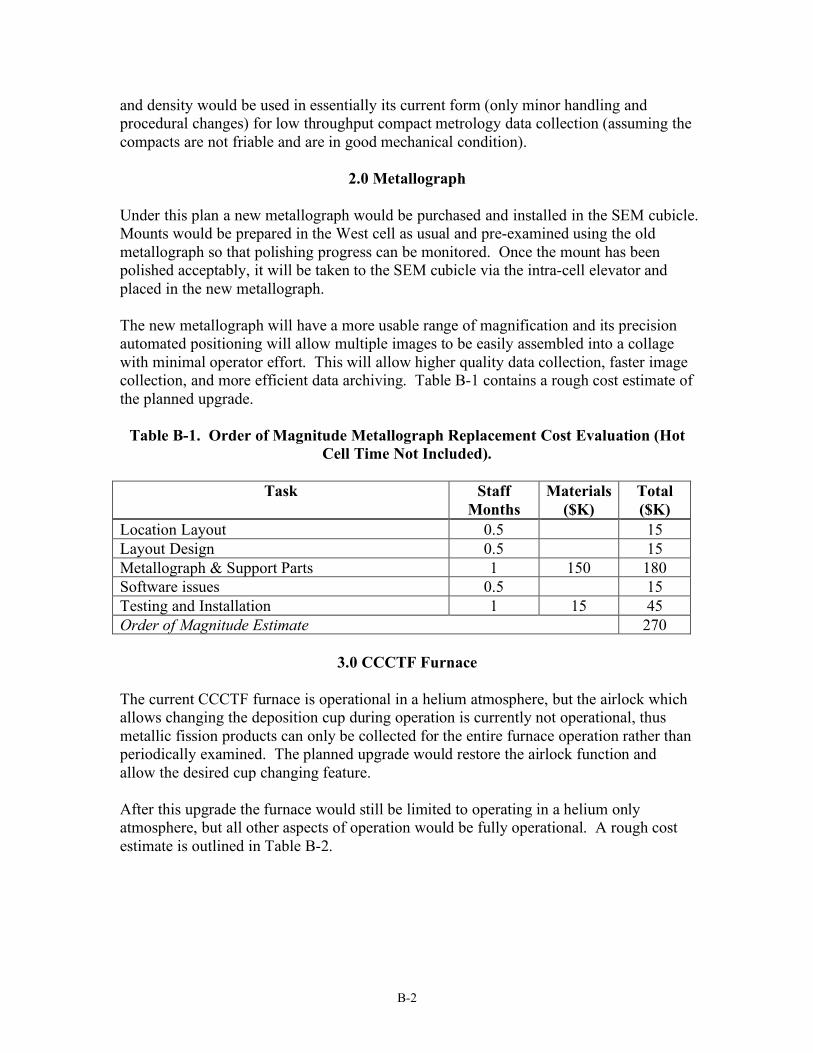
B-2
and density would be used in essentially its current form (only minor handling and procedural changes) for low throughput compact metrology data collection (assuming the compacts are not friable and are in good mechanical condition).
2.0 Metallograph Under this plan a new metallograph would be purchased and installed in the SEM cubicle. Mounts would be prepared in the West cell as usual and pre-examined using the old metallograph so that polishing progress can be monitored. Once the mount has been polished acceptably, it will be taken to the SEM cubicle via the intra-cell elevator and placed in the new metallograph. The new metallograph will have a more usable range of magnification and its precision automated positioning will allow multiple images to be easily assembled into a collage with minimal operator effort. This will allow higher quality data collection, faster image collection, and more efficient data archiving. Table B-1 contains a rough cost estimate of the planned upgrade.
Table B-1. Order of Magnitude Metallograph Replacement Cost Evaluation (Hot Cell Time Not Included).
Task Staff
Months Materials
($K) Total ($K)
Location Layout 0.5 15 Layout Design 0.5 15 Metallograph & Support Parts 1 150 180 Software issues 0.5 15 Testing and Installation 1 15 45 Order of Magnitude Estimate 270
3.0 CCCTF Furnace The current CCCTF furnace is operational in a helium atmosphere, but the airlock which allows changing the deposition cup during operation is currently not operational, thus metallic fission products can only be collected for the entire furnace operation rather than periodically examined. The planned upgrade would restore the airlock function and allow the desired cup changing feature. After this upgrade the furnace would still be limited to operating in a helium only atmosphere, but all other aspects of operation would be fully operational. A rough cost estimate is outlined in Table B-2.

B-3
Table B-2. Order of Magnitude Annealing Furnace Air Lock Refurbishment Cost Evaluation (Hot Cell Time Not Included).
Task Staff
Months Materials
($K) Total ($K)
Design/Upgrade 2 60 Fabrication 60 60 Testing and Installation 1 10 40 Order of Magnitude Estimate 160
4.0 IMGA The weak point of the current IMGA apparatus is the singulizer, the component that selects a single particle from the hopper of particles. This portion of the device can malfunction and damage particles. It is particularly troublesome with the smaller sized particles. This plan would replace the singulizer with a pneumatic motor slide system to avoid the problems associated with the current mechanical hopper feed system. An update of the control system and computer will also be required. The rest of the IMGA system would remain the same. A rough cost estimate is contained in Table B-3.
Table B-3. Order of Magnitude IMGA Cost Evaluation (Hot Cell Time Not Included).
Task Staff
Months Materials
($K) Total ($K)
New Singulizer Design 2 60 Fabrication 0.25 125 130 Control System 1 10 40 Software Issues 1 30 Testing and Installation 1 10 40 Order of Magnitude Estimate 300
5.0 LBL The LBL apparatus and would be rebuilt and any special equipment for handling the compacts and loose particles would be developed and constructed. This is expected to be a rather small effort as much of the LBL equipment used in the characterization task can be modified for use in the hot cell. The rest of the support equipment is not seen as a major effort. The cost is estimated in Table B-4.

B-4
Table B-4. Order of Magnitude LBL Cost Evaluation (Hot Cell Time Not Included).
Task Staff Months
Materials ($K)
Total ($K)
Design (based on past work) 0.25 8 Fabrication 0.25 15 22 Testing and Installation 0.5 15 30 Order of Magnitude Estimate 60
6.0 Compact Dimensional, Mass, and Density Measurements Currently, a set of general purpose dimensional measurement tools exist for use in the CCCTF cell. This equipment can be used to measure the diameter, length, mass, and immersion density of the fuel compacts. Only minor fixtures and procedure changes are necessary to proceed with low throughput compact measurements. Table B-5 contains a rough estimate of the minor changes required. The compacts are assumed to be in good mechanical condition and suitable for contact measurements.
Table B-5. Order of Metrology Cost Evaluation (Hot Cell Time Not Included).
Task Staff
Months Materials
($K) Total ($K)
Fixture changes 2 2 Procedures & test run 0.25 8 Order of Magnitude Estimate 10
7.0 Hot Cell Costs The actual installation and testing of the above equipment will require a considerable amount of hot cell resources. Table B-6 contains a rough estimate of the resources required for these tasks.
Table B-6. Order of Magnitude Hot Cell Cost Evaluation.
Task Cell
Days Materials
($K) Total ($K)
Metallograph 10 15 65 Furnace Airlock 5 40 IMGA 10 15 65 LBL 5 25 Metrology (general purpose) 5 25 Other Services (ES&H, criticality) 25 25 Order of Magnitude Estimate 245