object identi fi cation based on 3-d features using...
TRANSCRIPT

247Closed Loop Control of Soft Switched Forward Converter Using Intelligent Controller
IJCTA, 9(39), 2016, pp. 247-258© International Science Press
Object Identifi cation Based on 3-D Features Using Structured Light TechniqueC. R. Srinivasan* A. Vinothkumar** R. Senthilnathan*** R. Sivaramakrishnan**** and R. Srividya*****
Abstract : Three dimensional (3-D) vision techniques in the fi eld of Computer Vision aims mainly at reconstructing a scene to fi nd its three dimensional geometrical information. Active methods of sensing in a generic sense have better sensing abilities than passive methods since they release some form of energy into the environment for sensing. Structured Light technique in 3-D computer vision is one such active method which throws a light pattern on to the scene whose image is then captured by an intensity camera. The structured light technique is by far the most rugged of all 3-D reconstruction methods in the current scenario. The technique is so rugged that even passive methods such as stereo vision makes use of the pattern projection advantage thus resulting in many hybrid approaches. The paper presents an extremely low cost structured light method for scene reconstruction using off-the-shelf hardware. The objects considered are deliberately made texture-less and no contrast between the object and background is ensured so as to demonstrate the abilities of the structured light technique. The reconstructed information of the object is utilized for identifying its identity. The need comes in the form that such identifi cation processes cannot otherwise be done using 2-D visual features. The concept is validated for a set of three different cylindrical objects which basically vary in their slope of the top surfaces. The paper intends to demonstrate the ease of developing a complicated approach for 3-D vision using simple low-cost hardware and fi nally appreciates the wide range of application possible.Keywords : Structured Light, Camera Calibration, 3D Reconstruction, Object Identifi cation.
1. INTRODUCTION
Scene reconstruction in the fi eld of 3-D Computer Vision has been the topic of interest for over three decades. Many techniques viz. passive, active and hybrid techniques have evolved over the years. Passive methods for 3-D reconstruction aim at estimating the 3-D surface geometry with one or more passive cameras which records intensity information of the scene, while active vision techniques reconstructs a scene by estimating the depth indirectly by measuring the time of fl ight of light or other waves. This paper presents object identifi cation based on 3-D features using structured light technique. Object identifi cation techniques look for specifi c set of cues in the image whose range of values will form a set. Though 2-D object identifi cation has numerous applications and is in practice for a long time, the capabilities are restricted to 2-D feature set and anytime beyond that will demand multi-sensory information. Structured light technique is very similar stereo vision in terms of the underlying geometry in the imaging process just that one of the cameras is replaced by pattern projector. It overcomes the correspondence problem as
* Department of Instrumentation and Control, Manipal Institute of Technology, Manipal University, Manipal.** Department of Mechanical Engineering, Rajalakshmi Engineering College, Thandalam, India.*** Department of Mechatronics Engineering, SRM University, Kattankulathur, India.**** Department of Production Technology, MIT Campus, Anna University, Chennai, India***** Department of Electrical Engineering, Manipal Institute of Technology, Manipal University, Manipal. E-Mail: [email protected]
248 C. R. Srinivasan, A. Vinothkumar, R. Senthilnathan, R. Sivaramakrishnan and R. Srividya
in the case of stereo based reconstruction (it doesn’t demands conjugate points in the multiple images of the scene). Some authors have argued that structured light is a hybrid light technique as it projects external light in the scene and uses passive camera to capture.
Research in structures light has begun about two decades ago and it is the only 3-D reconstruction method which has the widest presence in the industrial and service applications of machine vision. Various structured light patterns are available and specially coded structured lights and its performance has been studied in various works. Even the shadows are used as pattern projector to reconstruct the object’s the volumetric information [2]. High accurate three dimensional image reconstructions has been achieved by projecting the patterns and acquired through the passive camera and applying stereo algorithm in extracting the volumetric information [3], it is an amalgamation of stereo and structured light technique.
In this paper a single strip pattern is utilized which is the often used one in industries. It is predominantly because of the fact that line scan camera could be used for a conveyor system and single strip suits line scan cameras. In order to have a relative motion and to imitate the industrial environment the objects are placed in a conveyor. Many portable systems have also been developed which can generate the 3D model of the objects [4]. Authors have attempted utilizing mirror based structured light approach which could give a complete 360 degree reconstruction of the scene [3]. The scenario such as template less objects with exactly equal base area but has variations in axis perpendicular to camera demands for 3D feature extraction. Dynamic reconstruction 3D model from a single image is possible using specially coded patterns [5] though the underlying principle of having the profi le information in the form 1-D offsets in the images remains the same. Laser light is used as the source as it has a special features that it divergence over long range of distance is very small. This property is mandate in any structured light projector so as to ensure reconstruction accuracy. Numerous images of the object at various instances are recorded. These images are integrated to have the 3D information model of the objects.
2. WORKING PRINCIPLE OF STRUCTURED LIGHT TECHNIQUE
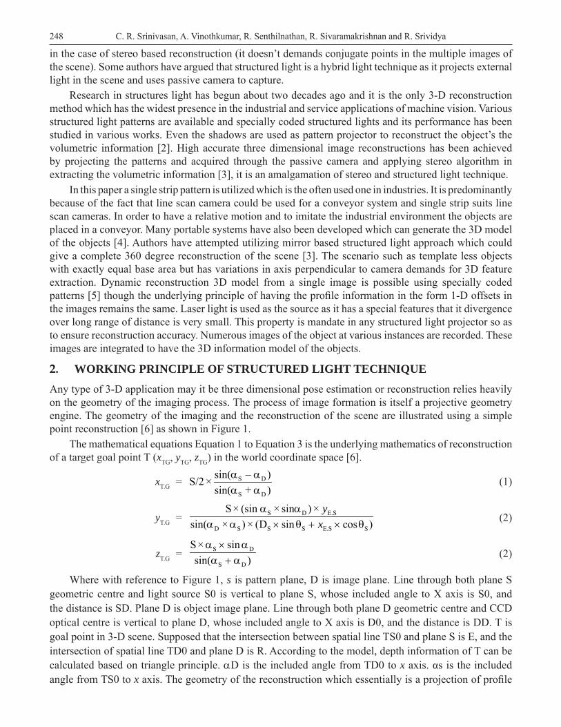
Any type of 3-D application may it be three dimensional pose estimation or reconstruction relies heavily on the geometry of the imaging process. The process of image formation is itself a projective geometry engine. The geometry of the imaging and the reconstruction of the scene are illustrated using a simple point reconstruction [6] as shown in Figure 1.
The mathematical equations Equation 1 to Equation 3 is the underlying mathematics of reconstruction of a target goal point T (xTG, yTG, zTG) in the world coordinate space [6].
xT.G = S D
S D
sin( – )S/2 ×sin( + )
(1)
yT.G = S D E.S
D S S S E.S S
S× (sin × sin ) ×sin( × ) × (D sin cos )
yx
(2)
zT.G = S D
S D
S× sinsin( )
(2)
Where with reference to Figure 1, s is pattern plane, D is image plane. Line through both plane S geometric centre and light source S0 is vertical to plane S, whose included angle to X axis is S0, and the distance is SD. Plane D is object image plane. Line through both plane D geometric centre and CCD optical centre is vertical to plane D, whose included angle to X axis is D0, and the distance is DD. T is goal point in 3-D scene. Supposed that the intersection between spatial line TS0 and plane S is E, and the intersection of spatial line TD0 and plane D is R. According to the model, depth information of T can be calculated based on triangle principle. D is the included angle from TD0 to x axis. αs is the included angle from TS0 to x axis. The geometry of the reconstruction which essentially is a projection of profi le
249Object Identifi cation Based on 3-D Features Using Structured Light Technique
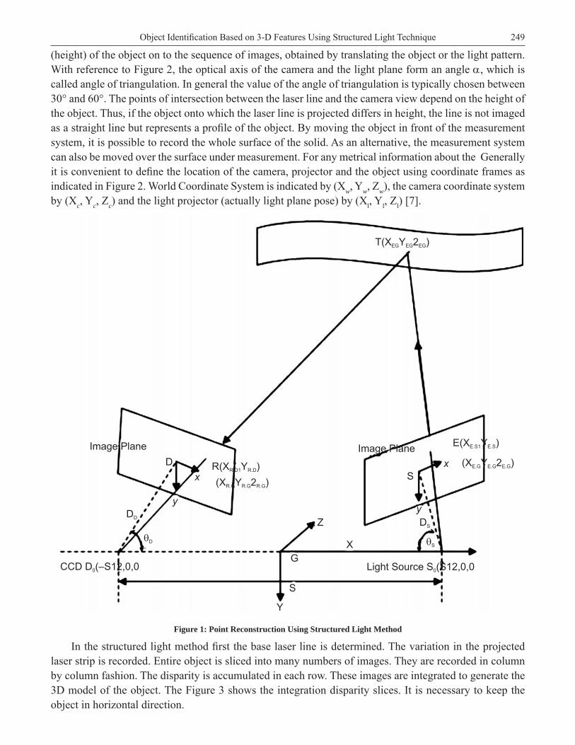
(height) of the object on to the sequence of images, obtained by translating the object or the light pattern. With reference to Figure 2, the optical axis of the camera and the light plane form an angle , which is called angle of triangulation. In general the value of the angle of triangulation is typically chosen between 30° and 60°. The points of intersection between the laser line and the camera view depend on the height of the object. Thus, if the object onto which the laser line is projected differs in height, the line is not imaged as a straight line but represents a profi le of the object. By moving the object in front of the measurement system, it is possible to record the whole surface of the solid. As an alternative, the measurement system can also be moved over the surface under measurement. For any metrical information about the Generally it is convenient to defi ne the location of the camera, projector and the object using coordinate frames as indicated in Figure 2. World Coordinate System is indicated by (Xw, Yw, Zw), the camera coordinate system by (Xc, Yc, Zc) and the light projector (actually light plane pose) by (Xl, Yl, Zl) [7].
Image Plane Image Plane
DD
DS
D
x
y
�D �S
CCD D (–S12,0,00 Light Source S (S12,0,00
Z
X
G
S
Y
R(X Y )R.D1 R.D
(X Y 2 )R.G R.G R.G
S
x
y
E(X Y )E.S1 E.S
(X Y 2 )E.G E.G E.G
T(X Y 2EG EGEG )
Figure 1: Point Reconstruction Using Structured Light Method
In the structured light method fi rst the base laser line is determined. The variation in the projected laser strip is recorded. Entire object is sliced into many numbers of images. They are recorded in column by column fashion. The disparity is accumulated in each row. These images are integrated to generate the 3D model of the object. The Figure 3 shows the integration disparity slices. It is necessary to keep the object in horizontal direction.
250 C. R. Srinivasan, A. Vinothkumar, R. Senthilnathan, R. Sivaramakrishnan and R. Srividya
Xw
Yw
Zw
X1
Y1
Z1
Zc
Yc
Xc
�
LASER LINE
CAMERA
IMAGE
OBJECT
Figure 2: Geometry of the Setup
Figure 3: Integration of Disparity
A model for structured light technique is created with few parameters. These parameters include ambiguity resolving which specifi es the method to be adopted when ambiguity arises in row wise disparity image. The parameter also includes gray value which specifi es the minimum gray value that the profi le strip should satisfy. The number of profi les can also be included which defi nes the total number of profi les that are taken for consideration.
3. EXPERIMENTAL SETUP
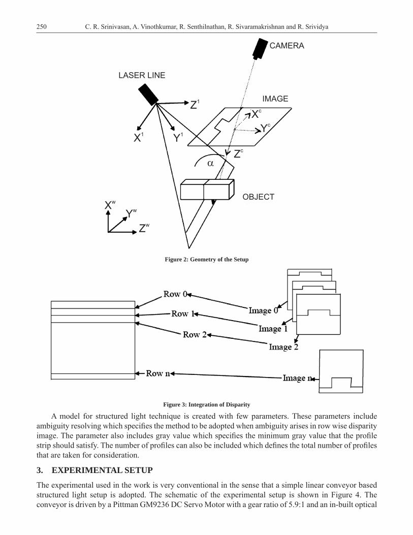
The experimental used in the work is very conventional in the sense that a simple linear conveyor based structured light setup is adopted. The schematic of the experimental setup is shown in Figure 4. The conveyor is driven by a Pittman GM9236 DC Servo Motor with a gear ratio of 5.9:1 and an in-built optical
251Object Identifi cation Based on 3-D Features Using Structured Light Technique
incremental encoder of 500 counts per revolution. The conveyor is provided with a couple of infra-red (IR) transmitter-receiver pair to make sure the number of frames taken completely covers the object sliding in the conveyor. It also helps as a means for synchronization with the computer running the reconstruction algorithm. The line strip pattern projector is an off-the-shelf barcode scanner with a laser light source. Though it is not comparable special purpose pattern projectors available exclusively for structured light technique, the scanner is very much justifi ed for a low cost system and the results of reconstruction are reasonably good. An 8-bit microcontroller (AT89C51) is used as a buffer for the purpose of motor control and reading the encoder signals. The encoder signals are not quadrature decoded; instead only pulse from a single channel is fed to a counter of the microcontroller so as to measure the speed. The position information is directly obtained from the IR sensors placed with a known distance of separation. The microcontroller communicates with the controller via serial RS232 protocol. The motor driver is a high frequency Darlington bipolar junction transistor to perform on-off control.
Figure 4: Schematic of the Experimental Setup
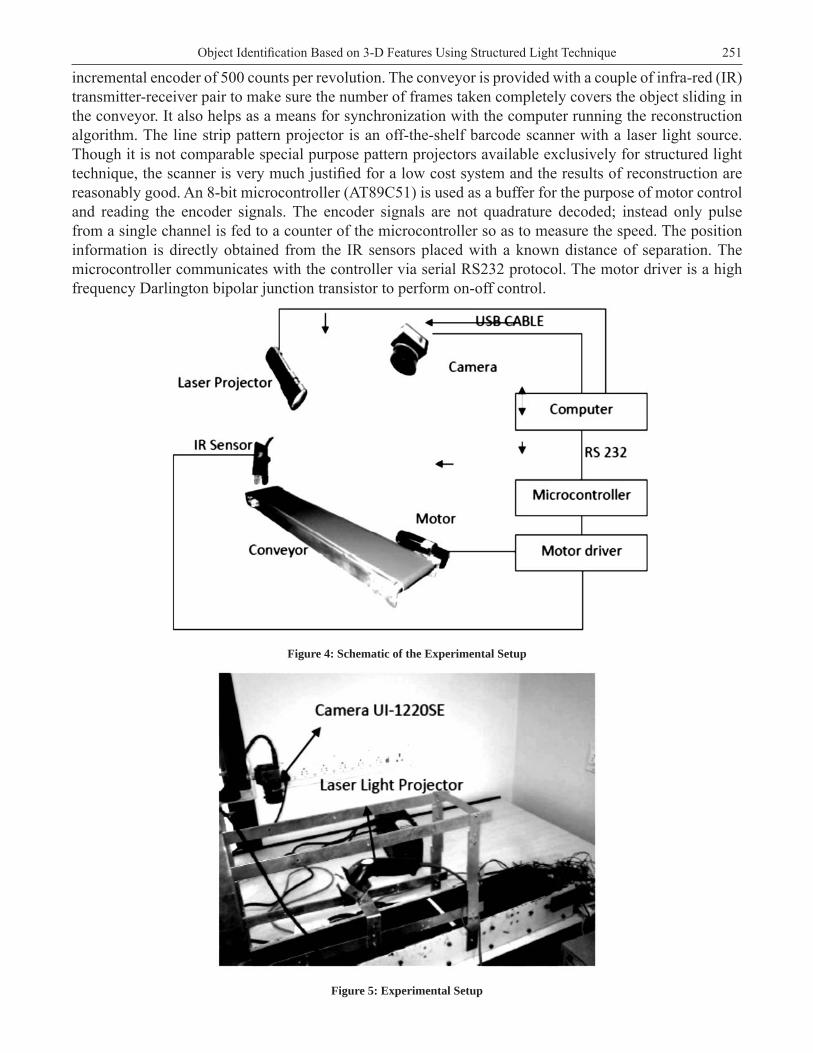
Figure 5: Experimental Setup

252 C. R. Srinivasan, A. Vinothkumar, R. Senthilnathan, R. Sivaramakrishnan and R. Srividya
The camera used is UI 1220SE-C from iDS which is a CMOS sensor based camera. The various specifi cation of the imaging system is listed in Table 1. The lens is a 16mm C-mount lens and a 0.5mm extension ring is used between the camera and the lens so as to conveniently cover the entire width of the conveyor. The system is fabricated as one completely integrated structure whose photograph is shown in Figure 5. The most challenging work in deciding the parameters of the camera is the frame rate of the camera which should be high enough to meet the conveyor velocity and choosing a compromise the exposure time (which affects the frame rate) and the lighting of the scene was another challenging part in the work. The process of fi nalizing the mentioned parameters involved many trials and fi nally narrowed down on the numbers specifi ed in Table 1. The software library used for the work is based on the Halcon software from MVTec Sofware GmbH.
Table 1
System Specifi cations
Specifi cation Value
Lens Focal Length 16 mm, C- Mount
FOV 160mm x 110mm
Aperture, f # 1.4
Working Distance 360 mm
Depth of Field 20 mm (max)
Camera Make iDS UI-1220SE-C
Camera Type Area Scan, Color (Operated in Monochrome Mode) Progressive CMOS
Camera Interface USB 2.0
Sensor Size 1/3”
Sensor Resolution 752 x 480
Spatial Resolution 0.21 mm/ pixel
Frame Rate 81 fps
Light Source (For Camera Calibration) White LED
Light Source (For Pattern Projection)Motorola Symbol LS1203
Class 1 Laser, Red (650nm to 700nm)
Hardware Platform 2.6 GHz Dual Core with 2GB primary memory and 1300MHz bus speed
4. SYSTEM CALIBRATION
The calibration of the structured light reconstruction system may be split into three segments namely, camera calibration, light plane pose calibration and fi nally calibration of the conveyor motion with respect to the camera’s rate of image acquisition.
A. Camera Calibration
Machine Vision algorithms especially 3D vision applications require equations linking the 3D coordinates of the points of the object with their corresponding image points. These equations are generally written in what is generally called the camera reference frame. But the camera reference frame is generally defi ned with respect to what is called as world reference frame. This frame of reference is generally used for reference to defi ne the pose and structure of the scene. The coordinates of the image points in the camera reference frame can be directly obtained from the pixel coordinates which are the only set of information

253Object Identifi cation Based on 3-D Features Using Structured Light Technique
available from the image. All these set of facts can be characterized into what is called as camera parameters viz., extrinsic parameters and intrinsic parameters. With reference to Figure 6, the world point is projected through the optical centre of the lens to the point ‘p’ in the image plane, which is located at a distance of f (the focal length) behind the optical centre. Actually, the term “focal length” is not quite correct and would be appropriate only for an infi nite object distance. To simplify matters, in the following section of the paper always the term “focal length” is used even if the “image distance” is meant. Although the image plane in reality lies behind the optical centre of the lens, it is easier to pretend that it lies at a distance of ‘f ’ in front of the optical centre, as shown in Figure 6.
Figure 6: Perspective Camera Model
Figure 7: Camera Calibration Images
Camera calibration is a necessary step in 3D computer vision in order to extract metric information from 2D images. Much work has been done in photogrammetry and relatively recently in computer vision [7]. Calibration is performed by observing a calibration object whose geometry in 3-D space is known with very good precision. The paper uses a hybrid method for partial calibration of the camera. A hybrid method based on photogrammetry and multi-plane calibration is used. The calibration procedure is the common multiplane calibration with a known calibration object. The images sequences for the calibration procedure is shown in Figure 7. The camera calibration estimates the internal camera parameters based on the direct estimation of the projection matrix of the camera. The lens distortion can be modelled as simple radial distortions since de-centering distortion (tangential distortions) can be considered as negligible in the current level of lens manufacturing tolerances. After the projection into the image plane, the lens
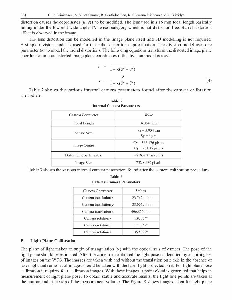
254 C. R. Srinivasan, A. Vinothkumar, R. Senthilnathan, R. Sivaramakrishnan and R. Srividya
distortion causes the coordinates (u, v)T to be modifi ed. The lens used is a 16 mm focal length basically falling under the low end wide angle TV lenses category which is not distortion free. Barrel distortion effect is observed in the image.
The lens distortion can be modelled in the image plane itself and 3D modelling is not required. A simple division model is used for the radial distortion approximation. The division model uses one parameter () to model the radial distortions. The following equations transform the distorted image plane coordinates into undistorted image plane coordinates if the division model is used.
u = 2 21 ( )u v
v = 2 21 ( )vu v (4)
Table 2 shows the various internal camera parameters found after the camera calibration procedure.
Table 2Internal Camera Parameters
Camera Parameter Value
Focal Length 16.8649 mm
Sensor SizeSx = 5.954 m
Sy = 6 m
Image CentreCx = 362.176 pixelsCy = 281.35 pixels
Distortion Coeffi cient, –858.478 (no unit)
Image Size 752 x 480 pixels
Table 3 shows the various internal camera parameters found after the camera calibration procedure.Table 3
External Camera Parameters
Camera Parameter Values
Camera translation x –23.7674 mm
Camera translation y –33.0059 mm
Camera translation z 406.856 mm
Camera rotation x 1.92754o
Camera rotation y 1.23269o
Camera rotation z 359.972o
B. Light Plane Calibration
The plane of light makes an angle of triangulation () with the optical axis of camera. The pose of the light plane should be estimated. After the camera is calibrated the light pose is identifi ed by acquiring set of images on the WCS. The images are taken with and without the translation on z axis in the absence of laser light and same set of images should be taken with the laser light projected on it. For light plane pose calibration it requires four calibration images. With these images, a point cloud is generated that helps in measurement of light plane pose. To obtain stable and accurate results, the light line points are taken at the bottom and at the top of the measurement volume. The Figure 8 shows images taken for light plane

255Object Identifi cation Based on 3-D Features Using Structured Light Technique
calibration. The Table IV shows the parameters of the pattern projector’s pose extracted during light plane calibration. Alpha, Beta and Gamma represents the orientation of the light plane pose with respect to the x, y and z axis of the World Coordinate System (WCS).
Figure 8: Images for Light Plane Calibration
Table 4Light Plane Pose Parameters
Parameter Value
Translation in x –0.992m
Translation in y –0.807m
Translation in z –0.0176m
Alpha 181.6o
Beta 9.877o
Gamma 359.7o
C. Conveyor Motion Calibration
Figure 9: Images for Conveyor Motion Calibration
Movement pose calibration is the calibration of movement of the object with respect to the measurement setup. The calibration plate is moved in discrete steps by the linear positioning system that will be used for the measurement of movement. To calibrate the movement of the linear positioning system, two images with different movement states are taken with countable movement steps. The calibration object‘s image is taken between two the acquisition of two successive profi les. The Figure 9 shows the calibration plates for movement pose calibration. The parameters obtained in movement pose calibration are as shown in Table 5. The transform corresponding to this movement is also expressed with respect to the WCS. The camera is operated at the frame rate of 81 frames per sec during the acquisition process.
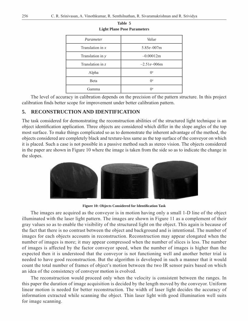
256 C. R. Srinivasan, A. Vinothkumar, R. Senthilnathan, R. Sivaramakrishnan and R. Srividya
Table 5Light Plane Pose Parameters
Parameter Value
Translation in x 5.85e–007m
Translation in y –0.00012m
Translation in z –2.51e–006m
Alpha 0o
Beta 0o
Gamma 0o
The level of accuracy in calibration depends on the precision of the pattern structure. In this project calibration fi nds better scope for improvement under better calibration pattern.
5. RECONSTRUCTION AND IDENTIFICATION
The task considered for demonstrating the reconstruction abilities of the structured light technique is an object identifi cation application. Three objects are considered which differ in the slope angles of the top most surface. To make things complicated so as to demonstrate the inherent advantage of the method, the objects considered are completely black and texture-less same as the top surface of the conveyor on which it is placed. Such a case is not possible in a passive method such as stereo vision. The objects considered in the paper are shown in Figure 10 where the image is taken from the side so as to indicate the change in the slopes.
Figure 10: Objects Considered for Identifi cation Task
The images are acquired as the conveyor is in motion having only a small 1-D line of the object illuminated with the laser light pattern. The images are shown in Figure 11 as a complement of their gray values so as to enable the visibility of the structured light on the object. This again is because of the fact that there is no contrast between the object and background and is intentional. The number of images for each objects accounts in reconstruction. Reconstruction may appear elongated when the number of images is more; it may appear compressed when the number of slices is less. The number of images is affected by the factor conveyor speed, when the number of images is higher than the expected then it is understood that the conveyor is not functioning well and another better trial is needed to have good reconstruction. But the algorithm is developed in such a manner that it would count the total number of frames of object’s motion between the two IR sensor pairs based on which an idea of the consistency of conveyor motion is evolved.
The reconstruction would proceed only when the velocity is consistent between the ranges. In this paper the duration of image acquisition is decided by the length moved by the conveyor. Uniform linear motion is needed for better reconstruction. The width of laser light decides the accuracy of information extracted while scanning the object. Thin laser light with good illumination well suits for image scanning.

257Object Identifi cation Based on 3-D Features Using Structured Light Technique
Figure 11: Inverted Sample Images of Object
Figure 12: Sample Reconstructed Information
The height is indicated through the different gray level in disparity image as discussed in Section II of the paper. So the difference between maximum and minimum gray value is a function of slope of the object. A sample reconstructed images of the object is shown in Figure 12. The three different objects have different slopes, using this data various trials are made on identifying the range of gray levels. For fl at object it had been found the range is below 30. The object with low slope the gray value range is about 85 and fi nally the last object results the gray value of range above 150. These distinct values help in identifying the objects. Tighter tolerances might be required for identifying objects with small variations in the surface slopes, though the objects considered did not demand one. The reconstructed image for all the three objects are shown in Figure 13
Figure 13: Reconstructed 3-D Information of the Objects Considered for Identifi cation

258 C. R. Srinivasan, A. Vinothkumar, R. Senthilnathan, R. Sivaramakrishnan and R. Srividya
6. CONCLUSIONS
The paper is an attempt to demonstrate the capabilities of the structured light technique for 3-D reconstruction with the help of a simple object identifi cation application. Since the decision making did not require pixel-level reconstruction accuracy, the setup and the calibration procedure were adequate enough. Inconsistencies were observed in the camera calibration and movement calibration which was predominantly because of the calibration plate which is a printed copy of the pattern utilized by the library. The movement calibration was inconsistent throughout because of the inherent nature of low-cost conveyor which has different velocities in the different position of their rotations. The qork may be extended further for application like exporting the reconstructed information to CAD package as in reverse engineering sense where more accurate information is required thus better calibration procedures.
7. REFERENCES 1. Agin G.J and Binford T.O. ―Computer description of curved Objects. IEEE Trans. Comp.,pp 439–449, 1976.
2. Batlle J, Mouaddib E, and Salvi E. Recent progress in coded structured light as a technique to solve the correspondence problem: a survey, pp 963–982, 1998.
3. Davis J and Chen X. ―A Laser Range Scanner for Minimum Calibration Complexity, In Proc. Third International Conference on 3-D Digital Imaging and Modelling, 2001.
4. Douglas Lanman, Daniel Crispell, and Gabriel Taubin, ―Surround Structured Lighting for Full Object Scanning, In 3-D Digital Imaging and Modeling, 2007
5. Jean-Yves Bouguet and Pietro Perona, ―3-D photography on your deskǁ, Technical report, California Institute of Technology, 1997.
6. McCallum B.C, Fright W.R ,Nixon M.A, and Price N.B. ―A Feasibility Study of Hand-held Laser Surface Scanning. In Proc. Image and Vision Computing New Zealand, pp 103–108, 1996
7. Ribo.M and Brandner .M, ―State of the art on vision-based structured light systems for 3-D measurementsǁ, In Proc. IEEE Int. Workshop on Robotic Sensors: Robotic and Sensor Environments, vol. 7, 2005
8. Salvi J, Pags J, and Batlle J, ―Pattern codifi cation strategies in structured light systemsǁ, Pattern Recognit., vol. 37, no. 4, pp. 827–849, 2004.
9. Z. Zhang, “A fl exible new technique for camera calibration’”, IEEE Transactions on Pattern Analysis and Machine Intelligence, vol.22, No.11, 2000, pp 1330–1334.
10. C.R. Srinivasan et al ,”Evaluation of Statistical Focus Measures in a Parallax Affected SFF-Inspired Approach”, IJCTA, volume 8 number 3, 2015, pp. 847-855.