object oriented design -ood
TRANSCRIPT

UniRoma2 - Service-oriented Software Engineering 1
Object Oriented Design - OOD• The OOD phase consists of the following two sub-phases:
– preliminary (or architectural, or system) OOD: defines the overall strategy to build a solution that solves the problem specified at OOA time. Decisions are taken that deal with the overall organization of the software (system architecture)
– detailed (or objects) OOD: provides the complete definition of classes and associations to be implemented, as well as the data structures and the algorithm of methods that implement class operations
• According to an iterative and incremental development approach, the OOA model is “transformed” into the OOD model, which adds the technical details of the hardware/software solution that defines how the software has to be implemented

UniRoma2 - Service-oriented Software Engineering 2
System architecture• A system architecture defines the structure of the software
system components along with the relationships between such components and the principles driving design and system evolution
• Evolution of system architectures:1. Mainframe-based architectures2. File sharing architectures3. Client/server (C/S) architectures:
3.1 two-tier (thin client, fat client)3.2 three-tier (upper layer, middle layer, bottom layer)
4. Distributed objects architectures5. Component-based architectures6. Service-oriented architectures
• Architectures from 3 through 6 are denoted as distributed architectures, or architectures of distributed software systems

UniRoma2 - Service-oriented Software Engineering 3
Distributed software systems• The processing of a distributed software system is
distributed over a set of independent execution hosts, which are connected by a network infrastructure (of either local area or wide area type)
• The set of independent execution hosts is seen by users as a single execution host
• Middleware technology has played an essential role in the transition from centralized architectures to distributed ones
• Middleware refers to the software layer that provides connectivity
• Such layer is in between the application and operating system layers and provides a set of services to establish the required interaction among the various application processes executed by networked hosts (e.g., TP monitor, RPC, MOM, ORB)

Example distributed software system
UniRoma2 - Service-oriented Software Engineering 4
Traffic control system: composed of multiple processes which are executed onto different processors (could be executed onto a single processor as well – it’s the set of separate processes that makes distributed a software system)

UniRoma2 - Service-oriented Software Engineering 5
Main features of distributed systems• Data and resource sharing• Openness (ability to manage heterogeneous
resources)• Concurrency• Scalability• Load balancing• Fault tolerance• Transparency• Adaptability to enterprise computing scenarios• Critical factors
– quality of service (performance, reliability, etc.)– interoperability– security

UniRoma2 - Service-oriented Software Engineering 6
Client/server (C/S) architectures• Each process plays the role of client or server
• The client process interacts with the user as follows:– provides the user interface to collect user requests
– forwards requests to servers, by use of middleware technology
– displays server responses back to the user through the user interface
• The server process (or the set of processes executed by a given host) provides services to the clients, as follows:– replies to client requests (it’s not the server that initiates the conversation with
the client)
– hides the complexity of the entire C/S system to the user (a given server may
in turn act as a client that forwards the initial request to a secondary server,
without making the client and the user aware of the forwarding chain)

UniRoma2 - Service-oriented Software Engineering 7
Client/server (C/S) architectures (2)A C/S architecture partitions software applications in terms of a set of separate processes, each acting as a client, a server or both

UniRoma2 - Service-oriented Software Engineering 8
Client/server (C/S) architectures (3)A C/S architecture partitions software applications in terms of a set of separate processes that are executed onto the same host (the processor) or on a group of networked hosts
Network
SC1SC2
CC1 CC2 CC3
CC5 CC6CC4
Servercomputer
Clientcomputer
s1, s2 s3, s4
c5, c6, c7
c1 c2 c3, c4
c8, c9 c10, c11, c12

UniRoma2 - Service-oriented Software Engineering 9
Application layers• Presentation layer
concerned with collecting user inputs and presenting the results of a computation to system users
• Application processing layerconcerned with providing application specific functionality, e.g., in a banking system, banking functions such as open account, close account, etc.
• Data management layerconcerned with managing access to application data
Presentation layer
Application processinglayer
Data managementlayer

UniRoma2 - Service-oriented Software Engineering 10
Two-tier C/S architectures • thin-client model: all of the application processing and data
management is carried out on the server; the client is simply responsible for running the presentation software
• fat-client model: the server is only responsible for data management; the software on the client implements the application logic and thepresentation software.
Thin-clientmodel
Fat-clientmodel Client
Client
ServerData management
Applicationprocessing
Presentation
Server
Datamanagement
PresentationApplication processing

UniRoma2 - Service-oriented Software Engineering 11
Three-tier C/S architectures • Each of the application architecture layers
executes on a separate processor• Allows for better performance than a two-tier thin-
client approach and is simpler to manage than a two-tier fat-client approach
• A more scalable architecture– as demands increase, extra servers can be added
Client
Server
Datamanagement
PresentationServer
Applicationprocessing

UniRoma2 - Service-oriented Software Engineering 12
Example C/S three-tier architecture
Database server
Customeraccountdatabase
Web server
Client
Client
Client
Client
Account serviceprovision
SQLSQL query
HTTP interaction
Internet Banking System

UniRoma2 - Service-oriented Software Engineering 13
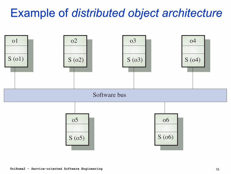
Distributed object architectures• No distinction between client and server• Each distributed object acts both as a client (by sending
request messages, i.e., by invoking methods) and as a server (by providing response messages, i.e., by executing the invoked method)
• The remote communication between objects is made transparent by use of middleware based on the software bus concept (referred to as object request broker):– abstract bus: specification of the interface providing
communication and data exchange services (control transfer model and type model for exchanged values)
– bus implementation: implementation of the abstract bus for a given HW/SW platform (Þ separation between interface and implementation)
• Applications based on distributed object architectures consists of a set of objects that are executed onto distributed and heterogeneous platforms and that communicates through remote method invocation

Distributed object architectures (2)
UniRoma2 - Service-oriented Software Engineering 14
UniRoma2 - Service-oriented Software Engineering 15
Example of distributed object architecture
Software bus
o1 o2 o3 o4
o5 o6
S (o1) S (o2) S (o3) S (o4)
S (o5) S (o6)

UniRoma2 - Service-oriented Software Engineering 16
BCED approach• Extension of the BCE approach• Introduces the Database Package, which groups the set of
classes responsible of the interface with the underlying database (native database interface, ODBC driver, JDBC driver)
• Such classes provide the operations used by entity objects (i.e., instances of classes in the Entity Package) to access data stored in the database
Boundary Package
Control Package
Entity Package
Database Package
Boundary Package
Control Package
Entity Package
Database Package

UniRoma2 - Service-oriented Software Engineering 17
Component-based architectures• Component-based architectures define software products
assembled from a set of software components, which are designed to work together as part of a component framework
• A component framework makes use of generic software architectures to formalize given classes of applications
• Component-based software systems support the efficient development of software systems whose requirements exhibit significant levels of variability
• It is thus necessary to identify and implement software abstractions that encapsulate efficient and reliable solutions to standard coordination and synthesis problems
• These abstractions, or “components”, are used to build bigger systems, while hiding the implementation details of the smaller structure
• A components can be used across many different applications, and can be reconfigured when application requirements

UniRoma2 - Service-oriented Software Engineering 18
Component-based architectures (2)• An essential element for building component-based software systems
is the black-box reuse of software
• Putting together components is simple, since each component has a limited set of “plugs” with fixed rules specifying how it may be linked with other components
• Instead of having to adapt the structure of a piece of software to modify its functionality, a user plugs the desired behavior into the parameters of the component
• Important aspects of components:– encapsulation of software structures as abstract components (variability)
– composition of components by binding their parameters to specific values, or other components (adaptability)

Component-based architectures (3)• Objects vs. components:
– objects encapsulate services, whereas components are abstractions (that can be used to construct object-oriented systems)
– objects have identity, state and behavior, and are always run-time entities; components, on the other hand, are generally static entities that are needed at system build-time (and do not necessarily exist at run-time).
– components may be of finer or coarser granularity than objects: e.g., classes, templates, mix-ins, modules; components should have an explicit composition interface, which is type-checkable
UniRoma2 - Service-oriented Software Engineering 19

Component framework
UniRoma2 - Service-oriented Software Engineering 20

Framework dev vs. Application dev
UniRoma2 - Service-oriented Software Engineering 21

UniRoma2 - Service-oriented Software Engineering 22
UML Components• A UML component is defined as:
«a physical and replaceable part of a system that conforms to and provides the realization of a set of interfaces»
• UML defines 5 standard stereotypes for components:– Executable (i.e., a directly executable module)– Library (i.e., a static library or a DLL)– Table (i.e., a database table)– File (i.e., a source code or data document)– Document (i.e., a human-readable document)

UniRoma2 - Service-oriented Software Engineering 23
Component characteristics• A unit of independent deployment
– never deployed partially• A unit of third-party composition
– sufficiently documented and self-contained to be “plugged into” other components by a third-party
• Has no persistent state– cannot be distinguished from copies of its own– in any given application, there will be at most one copy of a
particular component• Replaceable part of a system
– can be replaced by another component that conforms to the same interface
• Fulfills a clear function and is logically and physically cohesive
• May be nested in other components

UniRoma2 - Service-oriented Software Engineering 24
Component diagram• A UML component diagram shows the structure of
components, as well as the relationships between components
• Such relationships can be of two types:– dependency relationship– composition relationship
MaintainInvoiceUSP<<stored procedure>>
InvoiceDLL<<executable>>
InvoicingEXE<<executable>>

UniRoma2 - Service-oriented Software Engineering 25
Interfaces on component diagramRoomAllocEXE
ClassUSP
RoomUSP
Allocate
Reserve

UniRoma2 - Service-oriented Software Engineering 26
Deployment diagram
Client Browser
Web Server
Database Server
page requests
database requestsA UML deployment diagram is used to specify the software execution platform in terms of:– a set of nodes representing
computational resources
– connection relationships between nodes

UniRoma2 - Service-oriented Software Engineering 27
Allocation of components onto nodes• A computational nodes with processing capabilities
«executes» the components that are allocated onto it• A node together with the allocated components defines a
so called distribution unit
CorporateDatabaseServer
InvoiceUSPCustomerUSP
Corporate DatabaseServer
InvoiceUSP
CustomerUSP
Corporate DatabaseServer
InvoiceUSP
CustomerUSP

UniRoma2 - Service-oriented Software Engineering 28
Detailed OOD• Preliminary OOD provides the HW/SW execution platform to
which the detailed design sub-phase must conform• The main part of the detailed OOD sub-phase is devoted to
refine what produced in the OOA phase• The objective is to transform the OOA models, which have been
defined in the problem domain, into models defined in the solution domain, which in turn will be used in the coding phase
• The detailed OOD sub-phase provides the detailed design of the architectural unites identified in the preliminary OOD sub-phase, through the addition of technical details (or by producing additional models at a decreased level of abstraction)
• The detailed OOD sub-phase defines the collaboration between objects, which is at the basis of each object-oriented program
• Such a collaboration is defined through the realization of use cases and operations
• Collaborations are to OOD what use cases are to OOA– if use cases drive OOA then collaborations drive OOD

UniRoma2 - Service-oriented Software Engineering 29
Collaboration: UML notation• Similar to use cases, makes use of an ellipse with
a dashed line border• The realization relationship is represented by
directed edges labeled with the stereotype«realize»
Browse Student List
Add Student to Course Offering
Enter Program of Study
<<realize>>
<<realize>>

UniRoma2 - Service-oriented Software Engineering 30
Collaboration diagram• Interaction diagram typically preferred in the OOD
phase• Equivalent to the sequence diagram, which easily
becomes cumbersome when used in the OOD phase
• A collaboration diagram explicitly shows the static relations between interacting objects, along with the flow of messages that they exchange
• Provides the following advantages in the OOD phase:– improved readability of interactions when the number of
objects increases– ability to fully specify and annotate exchanged
messages

UniRoma2 - Service-oriented Software Engineering 31
From a sequence diagram...
: CustomeraConfWin :
ConfigurationWindowaComp : Computer
: ConfigurationItem
openNewgetConf
* getConfItem (out item_rec)displayComputer(item_recset)

UniRoma2 - Service-oriented Software Engineering 32
...to the equivalent collaboration diagram
The temporal sequence of message can be captured by introducing sequence numbers, which provide the progressive order according to which objects exchange messages (sequence numbers are optional)
aCust : Customer
aConfWin : ConfigurationWindow
aComp : Computer
aConfItem : ConfigurationItem
openNew
getConf
*getConf (out item_rec)
displayComputer (item_recset)

Message notations
UniRoma2 - Service-oriented Software Engineering 33
aBank1 : Bank
aCustomer1 : Customer
aCustomer2 : Customer
aBank2 : Bank
aCustomer3 : Customer
aBank3 : Bank
loanPlease (in amount_req, out amount_granted)
amount_granted := loanPlease (amount_req)
loanPlease
amount_grantedamount_req

UniRoma2 - Service-oriented Software Engineering 34
Realization of use cases• Use cases introduced at OOA time are realized
through collaborations at OOD time• A single use case is typically realized by a set of
collaborations, due to the different level of abstraction
• A collaboration has:– a structural part
• represents static aspects of collaboration• defined by elaborating the class diagram (in comparison with
its OOA version) with the implementation details– a behavioral part
• represents the dynamics that shows how the static elements collaborate
• defined by use of collaboration diagrams

UniRoma2 - Service-oriented Software Engineering 35
Collaboration – structural partRefer toOOA examples A.3 and A.6
PrereqCourseprereq_grade : String
prereq(out crsOID)
AcademicRecordcourse_code : Stringyear : Datesemester : Integergrade : String
prereqsSatisfied(out satisfied)
ProgramEntryWindow
add(std, crs, sem)destroy()
<<Boundary>>
Course<<PK>> course_code : String<<CK>> course_name : Stringcredit_points : Integer
areYouOpen(out c_check)prereq(out crs)addStudent(stdOID)
*
*
*
*
Gradegrade : Stringmark : Set<Number>
required_by
required_for
Student<<PK>> student_id : Stringstudent_name : Stringcurrent_fees : Money
areYouValid(out s_check)addCourse(crsoffOID)feesPaid(out paid)
0..*0..*
CourseOfferingyear : Datesemester : Integerenrolment_quota : Integer
areYouOpen(out c_check)addStudent(stdOID)
0..*0..*
*
*takes
*
*

UniRoma2 - Service-oriented Software Engineering 36
Collaboration – behavioral partRefer to
OOA examples A.3 and A.6
: ProgramEntryWindow
: Data Entry Person
aStudent : Student
anAcademicRecord : AcademicRecord
feesPaid(out paid)[c_check="no"]destroy[s_check="no"]destroy
aCourse : Course
aCourseOffering : CourseOffering
aPrereqCourse : PrereqCourse
prereqsSatisfied(out satisfied)
prereq(out crs)
areYouOpen(out c_check)
*prereq(out crsOID)
areYouValid(crs,out s_check)
areYouOpen(out c_check)
addCourse(crsoffOID)
addStudent(stdOID)
add(std,crs,sem)

UniRoma2 - Service-oriented Software Engineering 37
Collaboration – control managementUniversity Enrolment system• Example
– add a student (Student) to a course offering (CourseOffering)
• Actions to be executed1. identify the prerequisite courses for the course offering2. check if the student satisfies the prerequisites
• Consider that:– the enrol()message is sent by the boundary object :EnrolmentWindow
– three entity classes are involved – CourseOffering, Course and Student
• At least four solutions possible (with different class coupling characteristics)

UniRoma2 - Service-oriented Software Engineering 38
Control management - solution 1
: EnrolmentWindow
aCourseOffering : CourseOffering
aCourse : Course
aStudent : Student
enrol()
getAcadRec()
[prereq OK] enrol()
Policy maker
Mindless

UniRoma2 - Service-oriented Software Engineering 39
Control management – solution 2
: EnrolmentWindow
aCourseOffering : CourseOffering
aStudent : Student
aCourse : Course
enrol()
getPrereq()
[acad_rec OK] enrol()
Policy makerMindless

UniRoma2 - Service-oriented Software Engineering 40
Control management – solution 3
aCourseOffering : CourseOffering
: EnrolmentWindow
aCourse : Course
aStudent : Student
getPrereq() getAcadRec()
enrol()
Policy maker(the “God” class)

UniRoma2 - Service-oriented Software Engineering 41
Control management – solution 4
: EnrolmentWindow
aCourseOffering : CourseOffering
aCourse : Course
aStudent : Student
: EnrolmentPolicy
enrol()
getPrereq() getAcadRec()
[OK] enrol()The control object

Coupling and BCED approach• The BCED approach specifies four layers of
classes• Objects communicate within a layer and between
the adjacent layers• Intra-layer coupling
– desirable– localizes software maintenance and evolution to
individual layers• Inter-layer coupling
– to be minimized– communication interfaces to be carefully defined
• The Law of Demeter can be used to reduce the inter-layer class coupling
UniRoma2 - Service-oriented Software Engineering 42

UniRoma2 - Service-oriented Software Engineering 43
Law of Demeter• The target of a message (in class methods) can only be one of
the following objects:1. The method’s object itself (i.e. this in C++ and Java, self and
super in Smalltalk)
2. An object that is an argument in the method’s signature
3. An object referred to by the object’s attribute (strong law è inheritedattributes cannot be used to identify the target object)
4. An object created by the method
5. An object referred to by a global variable
• Also known as the “don’t talk to strangers”

UniRoma2 - Service-oriented Software Engineering 44
Realization of operations• Collaborations allow modeling complex operations
that involve a set of interacting objects
• Operations confined within one or two classes can be better designed by use of activity diagrams (in particular if they are algorithmically intensive)
• The same principle applies to operations parts of complex operations modeled as collaborations
• Finally, simpler operations can also be designed by use of pseudo-code, or PDL (program design language)

UniRoma2 - Service-oriented Software Engineering 45
Realization of operations (2)Example
void addStudent(Student std)
(class CourseOffering)
areYouOpen()do / check enrolment quotado / check current number of studentsdo / compare
students.add(std)
std.addCourseOff(this)
open
closed