object recognition using hough-transform clustering...
TRANSCRIPT

Object Recognition Using Hough-transform
Clustering of SURF Features
Viktor Seib, Michael Kusenbach, Susanne Thierfelder, Dietrich Paulus
Active Vision Group (AGAS), University of Koblenz-Landau
Universitatsstr. 1, 56070 Koblenz, Germany
{vseib, mkusenbach, thierfelder, paulus}@uni-koblenz.de
http://homer.uni-koblenz.de
Abstract—This paper proposes an object recognition approachintended for extracting, analyzing and clustering of features fromRGB image views from given objects. Extracted features arematched with features in learned object models and clustered inHough-space to find a consistent object pose. Hypotheses for validposes are verified by computing a homography from detectedfeatures. Using that homography features are back projectedonto the input image and the resulting area is checked forpossible presence of other objects. This approach is applied byour team homer[at]UniKoblenz in the RoboCup[at]Home league.Besides the proposed framework, this work offers the computervision community with online programs available as open sourcesoftware.
I. INTRODUCTION
The ability to memorize and redetect object instances isa key feature in modern computer vision applications androbotics. Such systems need to cope with many difficultiesin practical scenarios like a home environment. Typically,objects appear in different poses and in cluttered environments.Further, occlusion makes it difficult to determine exact bordersbetween objects and highly heterogeneous backgrounds areeasily mistaken for object parts. Finally, different illuminationschallenge the feature extraction process and add an additionaluncertainty to the object recognition process.
In our proposed approach we use Speeded Up RobustFeatures (SURF) [1] to cope with these challenges. SURF isa point feature detector which also provides a descriptor formatching. Its main advantage is the fast computation whilethe features are distinctive enough to enable robust objectrecognition even under difficult circumstances such as partialocclusion and cluttered background.
The descriptors from the extracted interest points arematched with objects from a database of features using nearest-neighbor matching. The identification of clusters for a certainobject was accomplished using Hough-transform clusteringto obtain valid object pose hypotheses. In the final step ahomography is built using the clustered features to verifyconsistent pose parameters and select the most probable objectpose for each recognized object.
While [2] already presented our approach briefly, it focusedon a comparison with a dense-statistical approach withoutdetailed algorithm description. Therefore, the contributions ofthis paper are as follows. We describe our object recognitionapproach in detail with a thorough explanation of each step.We then evaluate our algorithm with respect to changes in
important algorithm parameters. Finally, we provide an opensource implementation of our approach as a Robot OperatingSystem (ROS) package that can be used with any robot capableof interfacing ROS. The software is available at [3].
In Sec. II related approaches are briefly presented. Theseapproaches either use similar techniques or are used by otherteams competing in the RoboCup@Home league. Hereafter,Sec. III presents our approach in great detail, an evaluationfollows in Sec. IV. Finally, Sec. V concludes this paper.
II. RELATED WORK
Similar to our approach, Leibe and Schiele [4] use theHough-space for creating hypotheses for the object pose.Later, this concept was extended to the Implicit Shape Modelformulation in Leibe et al. [5]. Leibe et al. use the Harris cornerdetector [6] for key point extraction and image patches of25×25 pixels as local descriptors. In contrast to SURF descrip-tors, image patches used in the Implicit Shape Model are veryhigh dimensional. Thus, Leibe et al. use a special descriptorclustering technique to reduce the number of key points intoso-called codewords. Together with relative vectors pointingto the object’s center these codewords form the data basis forobject recognition. During recognition, matching codewordscast their votes for the object center into a continuous Hough-space. Maxima in Hough-space are considered true objectpositions. While this approach provides good results in general,it is not invariant to object rotation. This restriction impedesits usage in the RoboCup@Home for service robots.
Team Golem [7] and their object recognition approachplaced second in the RoboCup Technical Challenge of 2012.Golem uses the Multiple Object Pose Estimation and Detection(MOPED) framework proposed by Collet et al. [8] for objectrecognition. Similar to our approach, several images of eachobject are acquired during training. Scale Invariant FeaturesTransform (SIFT) [9] features are extracted from each imageand a 3D model of each object is reconstructed using structurefrom motion. In the recognition phase hypotheses for the objectpose are obtained with SIFT features extracted from the sceneand the previously created 3D model. In principle, a 3D objectmodel provides advantages over a method solely workingwith 2D images, especially if object manipulation is desired.However, 3D model creation in the MOPED framework makesthe training phase error-prone and time consuming. The cam-era has to be moved carefully around the object, while thebackground has to contain sufficient matching features insubsequent images. In contrast, our approach does not rely on
Scientific Cooperations International Workshops on Electrical and Computer Engineering Subfields 22-23 August 2014, Koc University, ISTANBUL/TURKEY
176

rgb image segmented object SURF object features
Preprocessing Feature extraction OutputInput
Fig. 1: Image processing pipeline for the training phase
Input Feature
extraction
Classification Output
rgb image SURF nearest-neighbor matching
Hough-transform clustering
homography calculation
verification
objects'
names
and poses
Fig. 2: Image processing pipeline for the recognition phase
background information for training and an object is usuallytrained in less than a minute.
The object recognition approach by team NimbRo@Homeconsist of a combined descriptor of SURF features and acolor histogram [10]. As usual, descriptors are obtained fromseveral object views in the training phase. During recognition,the extracted descriptors are compared to the database oflearned object descriptors. If matching descriptors are found,object hypotheses are tracked with a multi-hypothesis tracker.hypotheses confirmed over several frames are considered valid.
III. HOUGH-TRANSFORM CLUSTERING OF SURFFEATURES
Our object recognition approach is based on 2D cameraimages. In the training phase, SURF features are extractedand saved in a database. The recognition phase calculatesSURF features on an input image and matches features withthe database using nearest-neighbor matching. Wrong corre-spondences are removed and object pose transformations areclustered in a multi dimensional Hough-space accumulator.Finally, the matched features are verified by calculating ahomography.
From each image we extract a number of SURF featuresf . A feature is a tuple f = (x, y, σ, θ, δ) containing the position(x, y), scale σ and orientation θ of the feature in the image, aswell as a descriptor δ. Thus, the features are invariant towardsscaling, position in the image and in-plane rotations. They arealso robust towards changes in illumination and lesser off-plane rotations.
A. Training
The image processing pipeline for the training phase isshown in Fig. 1. In order to train the object recognitionclassifier an image of the background has to be captured.
Subsequently, an image of the object is acquired. From this twoimages a difference image is computed to separate the desiredobject from the background. Depending on the light conditions,the object might cast a shadow on its surroundings. Naturally,this shadow would appear in the difference image and thus beconsidered as part of the object. Therefore, the borders of theextracted object are adjusted to reduce the area contributed tothe object and thus remove shadows from the foreground. Fromthe acquired object image SURF features are extracted andstored in an object database. Further, images with a differentobject view are acquired and added to the object model in thedatabase. In their original publication, Bay et al. recommend30◦ as an optimal rotation between subsequently acquiredimages of an object for SURF computation [1]. However, it isnot necessary to acquire different rotations of the same objectview, since SURF features and the presented algorithm arerotation invariant.
B. Recognition
The image processing pipeline for the recognition phaseis shown in Fig. 2. During object recognition no informationabout the background is available. Thus, SURF features arecomputed on the whole input image. The obtained features arethen matched against the features stored in the object databaseusing nearest neighbor matching.
1) Nearest-Neighbor Matching: For each feature in theinput image the best feature in the database is obtained bycalculating a distance measure based on the euclidean distanceof the feature descriptors. Since simple distance thresholds donot perform well in high dimensional space, Lowe introducedthe distance ratio [9], which is used here. The distance ratiois the ratio of the euclidean distance to the best fitting and thesecond best fitting descriptor. If this quotient is low enough,the best fit is considered a matching feature. If the quotientis higher than a given threshold, the best and the second
Scientific Cooperations International Workshops on Electrical and Computer Engineering Subfields 22-23 August 2014, Koc University, ISTANBUL/TURKEY
177

(a)
y
(b) (c)
y
(d)
Fig. 3: The four dimensional accumulator is depicted as a red grid in (b) and (d), where the cell position along the two axesindicates the relative feature position. Inside each cell the horizontal and vertical translation encode the scale and rotation,respectively. Objects are recognized and hypotheses about the object pose are clustered in Hough-space using the accumulator.With correct objects, the feature position, rotation and scale match (a). Thus, the same accumulator bins in Hough-space areincremented for each feature, leading to a maximum, shown white (b). On the other hand, if wrong features are matched, theirrelative positions, as well as scale and rotation differ (c). Thus, their votes in the accumulator are scattered (gray) (d). Thesevotes are considered as outliers.
best descriptor fit almost equally well. This leads to theassumption that they are very likely the best matches onlyby chance and not because one of them actually matches thequery descriptor. The distance ratio also sorts out ambiguousmatches, which may result from repeated textures on objects.For the fast nearest-neighbor and distance computation in thehigh dimensional descriptor space we use an approximatenearest neighbor approach [11].
Since SURF features are calculated on the whole inputimage, including a potentially different background than in thetraining phase, not all features are matched in this step. Theresult of feature matching is a set of matches between featuresextracted from training images and the scene image. This setmay still contain outliers, i. e. matches between features whichdo not correspond to the same object point. These erroneouscorrespondences are discarded in the next step.
2) Hough-transform Clustering: Each feature match givesa hint of the object’s pose in the scene image. To cluster this in-formation from all feature matches, a four dimensional Hough-space over possible object positions (x, y, σ, θ) is created.Here, (x, y) is the position of the object’s centroid in the image,σ it’s scale, and θ it’s rotation. The goal is to find a consistentobject pose in order to eliminate false feature correspondencesfrom the previous step. This four dimensional accumulator isvisualized in Fig. 3 (b, d). The red grid represents translation inx- and y-directions. Inside each grid cell, the x-axis representsscale and the y-axis represents rotation. Thus, each pixel insidea grid cell corresponds to a bin.
Each feature correspondence is a hypothesis for an objectpose and is added to the corresponding bin in the accumulator.As suggested in [9] and [12], to reduce discretization errors,each hypothesis is added to the two closest bins in eachdimension, thus resulting in 16 accumulator entries per fea-ture correspondence. Clusters of maxima in the Hough-spacecorrespond to most probable object poses, whereas bins witherroneous object poses get only little votes (Fig. 3 (b,d)). Thus,outliers are removed and correct object poses are obtained. Forthe next steps only bins with at least five entries are considered,since we want to find a consistent pose applying homographycalculation. This low threshold helps finding small as well as
partially occluded objects in the scene.
We chose 10 bins for each dimension in the Hough-space, resulting in 104 bins describing different possible objectpositions in the image. Each feature correspondence votesinto 16 bins (the one it falls into and the closest ones ofeach dimension to avoid discretization errors). More bins perdimension would allow for a finer quantization of featureposes. However, this would also lead to potential maxima beingscattered among neighboring bins. Objects with sufficient fea-ture correspondences would be recognized with less confidenceor would not be recognized at all. Choosing less bins on theother hand would lead to feature correspondences voting forwrong object poses or even wrong objects.
To calculate the bin for the object position the centroid ofthe object in the scene cs has to be estimated. In the following,values with index o describe properties of an object acquiredduring the training phase, whereas values with index s refer tokey points found in a test scene during the recognition phase.The translation vector v′ from the centroid of the learned objectco to the position of the feature key point po on the object,normalized with the scale ratio of the scene key point σs andthe object key point σo is calculated according to Eq. 1.
v′ = (co − po)σs
σo
(1)
The resulting vector v′ has to be rotated to account forpossible object rotation in the scene. This is done by applyingEq. 2
v =
(
cosα − sinαsinα cosα
)
v′ (2)
where α = |θo− θs| is the minimal rotation angle betweenthe feature rotation θo of the object and the feature rotationθs in the scene. Finally, the estimated centroid of the objectin the scene cs is obtained by adding the feature’s position inthe scene ps to the calculated translation vector v (Eq. 3).
cs = (cxs, cys)T = v + ps (3)
Scientific Cooperations International Workshops on Electrical and Computer Engineering Subfields 22-23 August 2014, Koc University, ISTANBUL/TURKEY
178

The bins for the x- and y-location in the accumulator, ixand iy , are calculated as shown in Eq. 4 and Eq. 5,
ix =⌊cx,s
wbx
⌋
(4)
iy =⌊cy,s
hby
⌋
(5)
where w and h refer to the image width and height, andbx and by is the number of bins in the x- and y-dimensionof the Hough-accumulator, respectively. Apart from ix and iyalso the corresponding bins with position indices ix + 1 andiy + 1 are incremented to reduce discretization errors.
The index for the rotation bin is calculated using thedifference between the angles of the key point correspondencesα and the total number of bins reserved for the rotation inthe accumulator br. Originally, α is in [−π, π], thus Eq. 6normalizes the angle to be in [0, 2π].
i′r =(α+ π)br
2π(6)
To allow for the rotations by −π and π to be close togetherin the accumulator the final index for the rotation bin iscalculated according to Eq. 7.
ir = ⌊i′r⌋modbr (7)
Again, a second bin is used to reduce discretization errors.It’s index is calculated according to Eq. 8:
ir = ⌊i′r + 1⌋modbr. (8)
The fourth dimension in the accumulator encodes thescale the point of interest was found at. To determine theaccumulator bin for scale, first the ratio q between the scalesof the key point in the scene σs and in the learned object σo
is needed (Eq. 9):
q =σs
σo
. (9)
Further, the index is determined by the total number of binsused to represent scale bs and the number of octaves n usedfor SURF extraction and is calculated according to Eq. 10:
bs =
⌊
log2(q)
2(n− 1)+ 0.5
⌋
bs. (10)
As before, discretization errors are reduced by using asecond bin with the index bs + 1. All scales that go beyondthe range represented by the last bin are subsumed in the binfor the biggest scale of the accumulator.
As a result of the Hough-transform clustering all featureswith consistent poses are sorted into bins, while most outliersare removed because they do not form maxima in Hough-space(Fig. 3). So far, all features were processed independently of
all other features without taking into account the geometryof the whole object. With the resulting possible object posesfrom the Hough-transform clustering, the goal in the next stepis to find the best geometric match with all features in oneaccumulator bin.
3) Homography Calculation: In this step, bins representingmaxima in Hough-space are inspected in order to find the binthat matches best the object pose. All bins containing five keypoint correspondences or more are considered as maxima. Aperspective transformation is calculated between the featuresof a bin and the corresponding points in the database underthe assumption that all features lie on a 2D plane. As mostoutliers were removed by discarding minima in Hough-space,a consistent transformation is obtained here. Random SampleConsensus (RANSAC) is used to identify the best homographyfor the set of correspondences. The homography with mostpoint correspondences is considered to be the correct objectpose. Using the obtained homography the recognized objectcan be projected into the scene (Fig. 8). Since homographycalculation is computationally expensive the runtime of theobject recognition algorithm would increase considerably ifa homography was calculated for each bin. To speed up thealgorithm all bins are sorted in descending order consideringtheir number of features. A homography is calculated startingwith the bin containing the highest number of features. Thecalculation terminates if the next bin contains less features thanthe number of found point correspondences in the calculationof the best homography so far. The result is a homographydescribing the relative position, orientation and scale of thebest fitting training image for a test image, as well as thenumber of features supporting this hypothesis.
4) Verification of Results: The last step of our objectrecognition pipeline verifies the results. Using a threshold of aminimal matched feature number to verify the presence of anobject in the scene is futile since large and heterogeneouslystructured objects contain more features than small and ho-mogeneously structured objects. Instead, an object presenceprobability p is calculated as
p =fm
ft(11)
where fm is the number of matched features of that objectand ft is the total number of features that are present in thearea of the object. The number of features in the object areais calculated by projecting the object into the scene using thehomography and then counting all features in the boundingbox of the projected object.
IV. EVALUATION
This Section describes the different experiments performedto evaluate the presented object recognition approach. Experi-ments were performed to test the influence of the accumulatorsize, variable background and light conditions, as well aspartial occlusion on the performance of the classification.
For the verification step we used a threshold of p = 15 %(Eq. 11) and a minimum of 5 matched features per object.These two values have the most influence on the number offalse positive recognitions. If they are not chosen restrictively
Scientific Cooperations International Workshops on Electrical and Computer Engineering Subfields 22-23 August 2014, Koc University, ISTANBUL/TURKEY
179
(a) (b) (c)
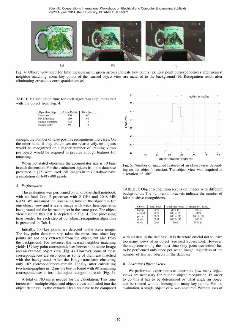
Fig. 4: Object view used for time measurement, green arrows indicate key points (a). Key point correspondences after nearestneighbor matching: some key points of the learned object view are matched to the background (b). Recognition result aftereliminating erroneous correspondences (c).
TABLE I: Calculation time for each algorithm step, measuredwith the object from Fig. 4.
Algorithm Step # Key Points Time [ms]
Detection 500 697
NN-Matching 139 61
Hough-clustering 102 13
Homography 98 12
enough, the number of false positive recognitions increases. Onthe other hand, if they are chosen too restrictively, no objectswould be recognized or a higher number of training viewsper object would be required to provide enough features formatching.
When not stated otherwise the accumulator size is 10 binsin each dimension. For the evaluation objects from the databasepresented in [13] were used. All images in this database havea resolution of 640×480 pixels.
A. Performance
The evaluation was performed on an off-the-shelf notebookwith an Intel Core 2 processor with 2 GHz and 2048 MBRAM. We measured the processing time of the algorithm forone object view and a scene image with weak heterogeneousbackground and the learned object in the same pose. The objectview used in this test is depicted in Fig. 4. The processingtime needed for each step of our object recognition algorithmis presented in Tab. I.
Initially, 500 key points are detected in the scene image.The key point detection step takes the most time, since keypoints are not only extracted from the object, but also fromthe background. For instance, the nearest neighbor matchingyields 139 key point correspondences between the scene imageand an example object view (Fig. 4). However, some of thesecorrespondences are erroneous as some of them are matchedwith the background. After the Hough-transform clusteringonly 102 correspondences remain. Finally, after calculatingtwo homographies in 12 ms the best is found with 98 remainingcorrespondences to form the object recognition result (Fig. 4).
A total of 783 ms is needed for the calculation. This timeincreases if multiple object and object views are loaded into theobject database, as the extracted features have to be compared
20
30
40
50
60
70
80
90
0 50 100 150 200 250 300 350
Featu
res
Object rotation (degrees)
Number of features
Fig. 5: Number of matched features of an object view depend-ing on the object’s rotation. The object view was acquired ata rotation of 180◦.
TABLE II: Object recognition results on images with differentbackgrounds. The numbers in brackets indicate the number offalse positive recognitions.
Object hom. back. weak het. back. strong het. back.
bscup 100 % 90 % (1) 100 %
nizoral 100 % 100 % (2) 90 %
perrier 100 % 100 % (1) 100 % (2)
ricola 100 % 100 % (1) 100 %
truck 100 % 90 % 70 % (1)
with all data in the database. It is therefore crucial not to learntoo many views of an object (see next Subsection). However,the step consuming the most time (key point extraction) hasto be performed only once per scene image, regardless of thenumber of learned objects in the database.
B. Learning Object Views
We performed experiments to determine how many objectviews are necessary for reliable object recognition. In orderto do this it has to be determined by what angle an objectcan be rotated without loosing too many key points. For theevaluation, a single object view was acquired. Without loss of
Scientific Cooperations International Workshops on Electrical and Computer Engineering Subfields 22-23 August 2014, Koc University, ISTANBUL/TURKEY
180
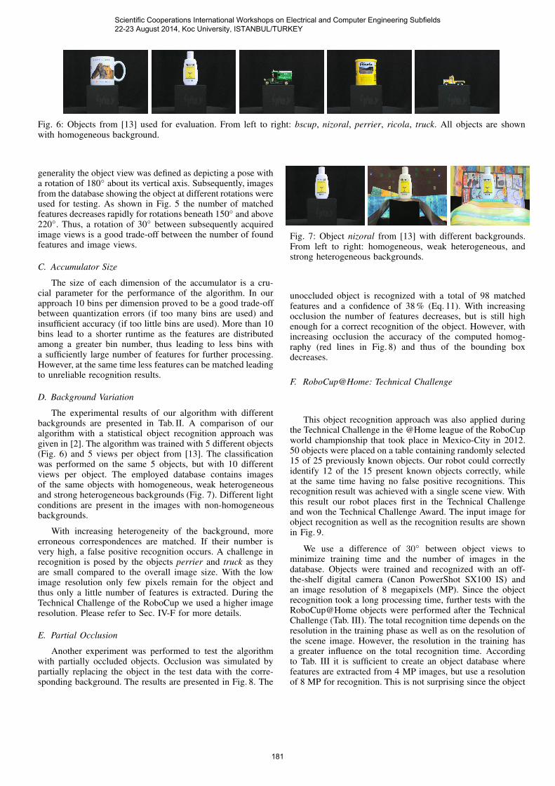
Fig. 6: Objects from [13] used for evaluation. From left to right: bscup, nizoral, perrier, ricola, truck. All objects are shownwith homogeneous background.
generality the object view was defined as depicting a pose witha rotation of 180◦ about its vertical axis. Subsequently, imagesfrom the database showing the object at different rotations wereused for testing. As shown in Fig. 5 the number of matchedfeatures decreases rapidly for rotations beneath 150◦ and above220◦. Thus, a rotation of 30◦ between subsequently acquiredimage views is a good trade-off between the number of foundfeatures and image views.
C. Accumulator Size
The size of each dimension of the accumulator is a cru-cial parameter for the performance of the algorithm. In ourapproach 10 bins per dimension proved to be a good trade-offbetween quantization errors (if too many bins are used) andinsufficient accuracy (if too little bins are used). More than 10bins lead to a shorter runtime as the features are distributedamong a greater bin number, thus leading to less bins witha sufficiently large number of features for further processing.However, at the same time less features can be matched leadingto unreliable recognition results.
D. Background Variation
The experimental results of our algorithm with differentbackgrounds are presented in Tab. II. A comparison of ouralgorithm with a statistical object recognition approach wasgiven in [2]. The algorithm was trained with 5 different objects(Fig. 6) and 5 views per object from [13]. The classificationwas performed on the same 5 objects, but with 10 differentviews per object. The employed database contains imagesof the same objects with homogeneous, weak heterogeneousand strong heterogeneous backgrounds (Fig. 7). Different lightconditions are present in the images with non-homogeneousbackgrounds.
With increasing heterogeneity of the background, moreerroneous correspondences are matched. If their number isvery high, a false positive recognition occurs. A challenge inrecognition is posed by the objects perrier and truck as theyare small compared to the overall image size. With the lowimage resolution only few pixels remain for the object andthus only a little number of features is extracted. During theTechnical Challenge of the RoboCup we used a higher imageresolution. Please refer to Sec. IV-F for more details.
E. Partial Occlusion
Another experiment was performed to test the algorithmwith partially occluded objects. Occlusion was simulated bypartially replacing the object in the test data with the corre-sponding background. The results are presented in Fig. 8. The
Fig. 7: Object nizoral from [13] with different backgrounds.From left to right: homogeneous, weak heterogeneous, andstrong heterogeneous backgrounds.
unoccluded object is recognized with a total of 98 matchedfeatures and a confidence of 38 % (Eq. 11). With increasingocclusion the number of features decreases, but is still highenough for a correct recognition of the object. However, withincreasing occlusion the accuracy of the computed homog-raphy (red lines in Fig. 8) and thus of the bounding boxdecreases.
F. RoboCup@Home: Technical Challenge
This object recognition approach was also applied duringthe Technical Challenge in the @Home league of the RoboCupworld championship that took place in Mexico-City in 2012.50 objects were placed on a table containing randomly selected15 of 25 previously known objects. Our robot could correctlyidentify 12 of the 15 present known objects correctly, whileat the same time having no false positive recognitions. Thisrecognition result was achieved with a single scene view. Withthis result our robot places first in the Technical Challengeand won the Technical Challenge Award. The input image forobject recognition as well as the recognition results are shownin Fig. 9.
We use a difference of 30◦ between object views tominimize training time and the number of images in thedatabase. Objects were trained and recognized with an off-the-shelf digital camera (Canon PowerShot SX100 IS) andan image resolution of 8 megapixels (MP). Since the objectrecognition took a long processing time, further tests with theRoboCup@Home objects were performed after the TechnicalChallenge (Tab. III). The total recognition time depends on theresolution in the training phase as well as on the resolution ofthe scene image. However, the resolution in the training hasa greater influence on the total recognition time. Accordingto Tab. III it is sufficient to create an object database wherefeatures are extracted from 4 MP images, but use a resolutionof 8 MP for recognition. This is not surprising since the object
Scientific Cooperations International Workshops on Electrical and Computer Engineering Subfields 22-23 August 2014, Koc University, ISTANBUL/TURKEY
181

(a) (b) (c) (d)
Fig. 8: Example images for detection of partially occluded objects. The unoccluded object is recognized with 98 matched featuresand 38 % confidence (a). The occluded object have less features, but are still recognized correctly: 49 with 33 % (b), 17 with17 % (c), and 34 with 34 % (d).
(a)
(b)
Fig. 9: The input image for object recognition as acquired by our robot during the Technical Challenge of the RoboCup (a) andthe output image depicting the recognition results (b). During training and recognition an image resolution of 8 MP was used.
to camera distance is usually smaller during training thanduring recognition. Thus, even with a lower image resolutiona sufficient number of features can be extracted and saved inthe database during training.
V. CONCLUSION
We presented our object recognition approach that we usein the RoboCup@Home league. Our approach is based onSURF features that are clustered in Hough-space. Hough-clustering allows us to discard most erroneous correspondencesin the detection step. Subsequently, homographies are calcu-
Scientific Cooperations International Workshops on Electrical and Computer Engineering Subfields 22-23 August 2014, Koc University, ISTANBUL/TURKEY
182

TABLE III: Comparison of different image resolutions andtheir effect on recognition time and recognition quality.
Resolution Resolution Recognition True False
Training [MP] Scene [MP] Time [s] Positives Positives
4 4 20 5 1
4 8 26 12 0
8 4 53 6 1
8 8 117 12 0
lated to take into account the relative positions of all featureson the object. The homography that best matches the objectgeometry is back projected into the scene image to indicatethe position of the recognized object.
Our recognition approach performs well on images withcluttered background and partially occluded objects. Objectsat different scales and with arbitrary poses in the scene imageare recognized reliably. For best results, it is recommended touse high resolution images in order to extract sufficient featuresfor object representation.
This object recognition algorithm is available as an opensource ROS package and can be downloaded from [3]. Apartfrom the recognition algorithm itself, the ROS package pro-vides a convenient GUI to learn new object models and test therecognition. With this GUI new object models can be learnedin less then a minute.
Our future work will concentrate on further evaluating andoptimizing our approach. We plan to test several key pointdetectors and descriptors, as well as test different Hough-clustering techniques.
REFERENCES
[1] H. Bay, T. Tuytelaars, and L. J. V. Gool, “SURF: Speeded up robustfeatures,” ECCV, pp. 404–417, 2006.
[2] P. Decker, S. Thierfelder, D. Paulus, and M. Grzegorzek, “Dense Statis-tic Versus Sparse Feature Based Approach for 3D Object Recognition,”Pattern Recognition and Image Analysis, vol. 21, no. 2, pp. 238–241,2011.
[3] AGAS. (2014, Jul.) Ros package for object recognition basedon hough-transform clustering of surf. [Online]. Available: http://wiki.ros.org/agas-ros-pkg
[4] B. Leibe and B. Schiele, “Interleaved object categorization and segmen-tation,” in BMVC, 2003.
[5] B. Leibe, A. Leonardis, and B. Schiele, “Combined object categoriza-tion and segmentation with an implicit shape model,” in ECCV’ 04
Workshop on Statistical Learning in Computer Vision, 2004, pp. 17–32.
[6] C. Harris and M. Stephens, “A combined corner and edge detector,” inFourth Alvey Vision Conference, Manchester, UK, 1988, pp. 147–151.
[7] L. A. Pineda, C. Rascon, G. Fuentes, V. Estrada, A. Rodriguez, I. Meza,H. Ortega, M. Reyes, M. Pena, J. Duran et al., “The golem team,robocup@ home 2014.”
[8] A. Collet, M. Martinez, and S. S. Srinivasa, “The moped framework:Object recognition and pose estimation for manipulation,” The Interna-
tional Journal of Robotics Research, p. 0278364911401765, 2011.
[9] D. G. Lowe, “Distinctive image features from scale-invariant keypoints,”International Journal of Computer Vision, vol. 60, no. 2, pp. 91–110,2004.
[10] J. Stuckler and S. Behnke, “Integrating indoor mobility, object ma-nipulation, and intuitive interaction for domestic service tasks,” inHumanoid Robots, 2009. Humanoids 2009. 9th IEEE-RAS International
Conference on. IEEE, 2009, pp. 506–513.
[11] M. Muja, “Flann, fast library for approximate nearest neighbors,” 2009,http://mloss.org/software/view/143/.
[12] W. E. L. Grimson and D. P. Huttenlocher, “On the sensitivity of thehough transform for object recognition,” IEEE Transactions on Pattern
Analysis and Machine Intelligence, vol. PAMI-12, no. 3, pp. 255–274,1990.
[13] M. Grzegorzek and H. Niemann, “Statistical object recognition includ-ing color modeling,” in 2nd International Conference on Image Analysis
and Recognition. Toronto, Canada: Springer, 2005, pp. 481–489.
Scientific Cooperations International Workshops on Electrical and Computer Engineering Subfields 22-23 August 2014, Koc University, ISTANBUL/TURKEY
183