objective - portland state...
TRANSCRIPT

1
Happy Fun TimesThe Story of a Networked Precipitation Model
James Manzoine & Kumkum Bhattacharyya
Objective:
Objectives of this project are:
I. Create a geometric network based on coordinate point locations that represent the a municipal sewer system.
II. Generate a terrain model that represents the watershed characteristics of that sewer systems topography.

2
Developing the Geodatabase and ArcHydro Model
Hydrologic Modeling
Arc Hydro Geodatabase
Hydrologic Information System (Maidment, 2002)
ArcHydro data model for water resources
3
Working Steps
• Field Work: Gathering GPS Coordinates• Network: Establishing Topology and Relations
in Building a Geometric Network• Terrain Assessment: Building a Watershed
Based on a DEM• Modeling: Relating the Network to the
Watershed• Results: A Time Series Hydrograph
Representing Discharge Rates per Outfall
A Friendly Neighborhood

4
The Study Area
Surveying the FieldAn isolated area was selected on DEM
►Looked for area with few external sources and descent relief in elevation►GPS coordinates recorded for all manholes, inlets, and outfalls via Goe XT►GPS coordinates imported and converted to .SSF file via GPS Pathfinder 3.2►Coordinate locations imported as table into ArcGIS and converted into a point shapefile

5
Point Attributes
Building Drainage Network►A geodatabase was created and a feature dataset was established to store network features.►The point shapefile was then imported into the feature dataset and polyline shapefile were then created and imported into ArcMap► Polylines were then digitized in the direction of flow to represent pipe connections of the sewer system►A geometric network was then established using the point locations and digitized polylines.►This created a system of junction points which will later be used to populate the maps visual features.

6
Terrain Processing
► A DEM of the area was clipped to encompass on the area of interest before the sinks were filled using the “Fill” tool.
► ArcHydro was then opened, and the Terrain Preprocessing tools were utilized.
These tools were used to establish the following layers:
• Flow directions• Flow accumulations• Stream definitions• Stream segmentations• Catchments polygons• Flow lines• Adjoined catchments• Drainage points, slopes• Flow paths
Terrain Elevation

7
Flow directions
Flow Accumulations & Slope
8
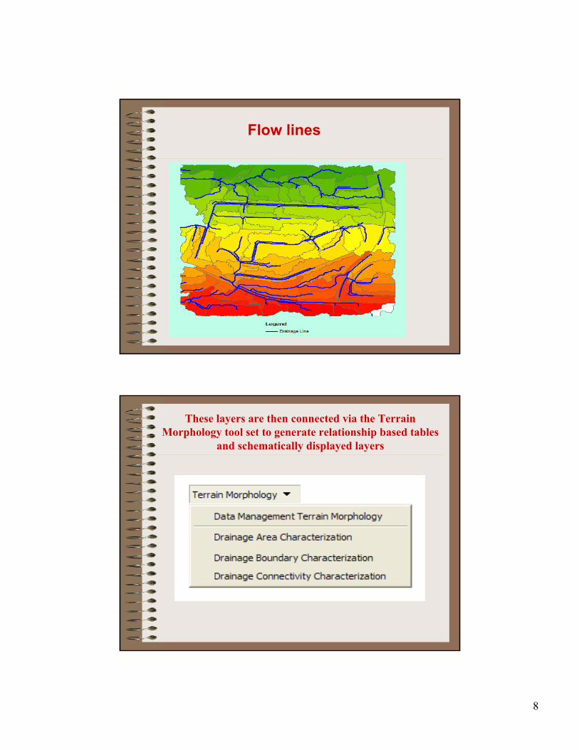
Flow lines
These layers are then connected via the Terrain Morphology tool set to generate relationship based tables
and schematically displayed layers

9
►Upon generating the desired layers and establishing the appropriate connections a hydro network was established to represent the dynamics of watershed flow
►This network is based off of the flow lines, drainage points, and catchments that were generated via Terrain Processing.
Watershed Networking
Watershed

10
Attribute Building
► Now that the hybrid network models are built, several attribute fields must be calculated for modeling relationships
►These attributes include HydroIDs, To/From Nodes, NextDownIDs, DrainIDs, GridIDs, FlowDir, LengthDown, and Type fields.
►The vast majority of these fields were established via Attribute Tools in ArcHydro, but some like DrainID and GridID were established by spatial and attribute joins.
►Upon calculating the attributes of the models, the junctions were then assigned an Ancillary Role (Source, Sink, or None).
Relationship Building
► Catchments Have Drainage Points (HydroID -> GridID)
►DrainagePoints Have Watershed Junctions (JunctionID -> HydroID) Note: Specified Connections were Joined Together Manually
►Watershed Junctions Have Network Junctions (HydroID -> DrainID) Note: This relationship is the hybrid point of the two models
►Network Junctions Have Network Drainage Points (HydroID -> JunctionID)
►Network Drainage Points Have Network Outfall Sinks (HydroID -> DrainID)
►Network Junctions Have Network Outfall Sinks (HydroID -> JunctionID)
►Network Sinks Have Values Table (HydroID -> SinkID)Note: This relationship stores accumulation data
11
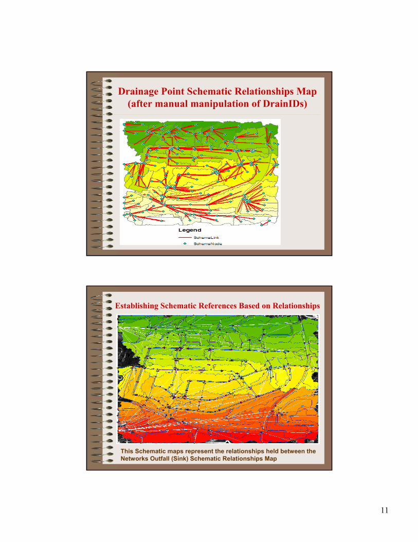
Drainage Point Schematic Relationships Map (after manual manipulation of DrainIDs)
Establishing Schematic References Based on Relationships
This Schematic maps represent the relationships held between theNetworks Outfall (Sink) Schematic Relationships Map

12
Attribute Consolidation and Accumulation
• The attribute tables of both models were separately consolidated and accumulated.
• Consolidating the related attribute fields summarizes the properties of features in one related class to another
• Accumulating the related attribute fields assigns drainage area properties downstream
Consolidate / Accumulate Attributes

13
Modeling Intentions
• Combine Network to Watershed• Integrate Precipitation Data to Model• Make the Network “active” in Draining
Catchments• Automate Drainage Over Time• Produce Time Series Data for Discharge
Rates
Compute Local ParametersUpon generating all of these layers and relationships the model was set “Compute Local Parameters”
This tool took the precipitation data and implied it to model to generate volumetric results in the assigned data table.
Results:
The map failed to model the results ...
Questions?????

14
Reasons Why?
• After many attempts and discussions with Dr. Duh, we determined that ESRI cannot support two Hybrid models.
• This is because a Sink in one model cannot be determined as a Source in another.
• In order to properly represent the model one must make a single master model that with separate sink watersheds.
Watershed

15
Establishing Schematic References Based on Relationships
This Schematic maps represent the relationships held between theNetworks Outfall (Sink) Schematic Relationships Map
Drainage Point Schematic Relationships Map (after manual manipulation of DrainIDs)

16
Future Plans?
• Future attempts might be made on correcting this model, but no promises will be made at this point.
• Mike Urban: A software program that might be able to correctly model a sewershed.
References
• Carlos Patino-Gomez, Daene C. McKinney and David R. Maidment. 2007. Water Quality Data Model in GIS for the Rio Bravo/Grande basin,
• http://www.crwr.utexas.edu/gis/gishydro07/SpaceAndTime/ESRI_2007_Patino.htm
• ESRI Virtual Campus Course, Creating and Integrating Data for Natural Resource Applications, completed ESRI certified Training, 12 course hours, December, 2006
• ESRI Virtual Campus Course, Creating, Editing, and Managing Geodatabases for ArcGIS Desktop, ESRI certified Training in progress
• Maidment, David R (Ed). 2002. Arc Hydro. GIS for Water Resources, ESRI press, California, 203 pp.
• http://webhelp.esri.com/arcgisdesktop/9.2/index.cfm?TopicName=Geometric_network_connectivity_rules, accessed on November 25th, 2008

17
Questions?
Thanks!