oblique flying wings: an introduction and white paper1 · oblique flying wings: an introduction and...
TRANSCRIPT

Oblique Flying Wings: An Introduction and White Paper1
Desktop Aeronautics, Inc. June 2005
Abstract
The purpose of this white paper is to provide a range of information to potential designers of oblique wing aircraft, including theoretical and conceptual foundations, general performance characteristics and mission-based optimization, more detailed parametric design studies, and other supporting resources. A collection of technical papers related to oblique wings has been compiled as part of this study. Many of these papers have not been widely distributed, but are now available and linked to this paper.
1. Introduction to Oblique Flying Wings In 1958, R.T. Jones suggested that aircraft with asymmetrically-swept (oblique) wings would offer many advantages at high transonic and low supersonic speeds. However, a variety of uncertainties and technological difficulties associated with this unusual configuration have prevented its application to operational aircraft. In the past several decades, the technology needed to resolve these issues has developed rapidly and oblique-wing aircraft now appear to present attractive alternatives to conventional designs in certain civil and military roles.
Many of the technical challenges of oblique wings arise from their nonlinear and strongly-coupled aerodynamic characteristics. For example, significant variations in rolling moment with changes in angle of attack are observed. Unusual inertial couplings and aeroelastic characteristics further complicate the dynamics of such aircraft and for certain oblique wing configurations propulsion integration is problematic.
These challenges are especially formidable for all-wing configurations that lack the powerful stability and control contributions from traditional tails. Stability is an issue because of the limited alternatives for packaging payload, propulsion, and aircraft systems into the wing to achieve a desired center of gravity location. Control may be difficult because of relatively short moment-arms and the changes in control effectiveness with large changes in wing sweep.
Modern computational methods provide much more rapid analysis of vehicle force and moment characteristics, control effectiveness, and other performance characteristics. Modern flight control system technology now makes a strongly coupled, unstable vehicle more feasible, creating renewed interest in the potential performance advantages of oblique flying wings. However, much of the experience gained over the past 50 years of oblique wing development is not supplanted by rapid turn-around simulation-based design tools and the present paper is intended to highlight some of the important lessons from previous research.
1 On-line version available at: http://www.desktopaero.com/obliquewing/
1.1 Basic Concepts and Motivation
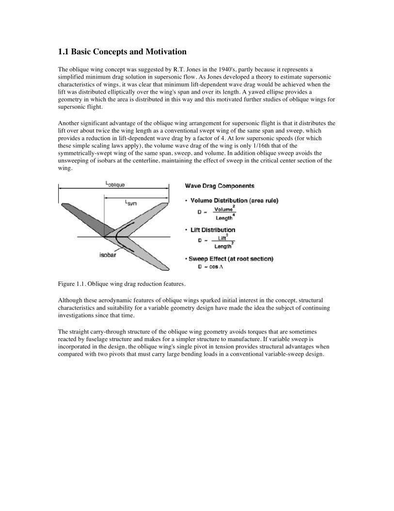
The oblique wing concept was suggested by R.T. Jones in the 1940's, partly because it represents a simplified minimum drag solution in supersonic flow. As Jones developed a theory to estimate supersonic characteristics of wings, it was clear that minimum lift-dependent wave drag would be achieved when the lift was distributed elliptically over the wing's span and over its length. A yawed ellipse provides a geometry in which the area is distributed in this way and this motivated further studies of oblique wings for supersonic flight.
Another significant advantage of the oblique wing arrangement for supersonic flight is that it distributes the lift over about twice the wing length as a conventional swept wing of the same span and sweep, which provides a reduction in lift-dependent wave drag by a factor of 4. At low supersonic speeds (for which these simple scaling laws apply), the volume wave drag of the wing is only 1/16th that of the symmetrically-swept wing of the same span, sweep, and volume. In addition oblique sweep avoids the unsweeping of isobars at the centerline, maintaining the effect of sweep in the critical center section of the wing.
Figure 1.1. Oblique wing drag reduction features.
Although these aerodynamic features of oblique wings sparked initial interest in the concept, structural characteristics and suitability for a variable geometry design have made the idea the subject of continuing investigations since that time.
The straight carry-through structure of the oblique wing geometry avoids torques that are sometimes reacted by fuselage structure and makes for a simpler structure to manufacture. If variable sweep is incorporated in the design, the oblique wing's single pivot in tension provides structural advantages when compared with two pivots that must carry large bending loads in a conventional variable-sweep design.

Figure 1.2 Structural advantages of oblique wings.
Perhaps the most significant advantage of oblique wings for variable sweep aircraft was recognized in a 1940's design by Blohm and Voss which used oblique variable sweep to avoid the undesirable aerodynamic center shift common with symmetric variable sweep.
Figure 1.3. Oblique variable sweep reduces some of the aerodynamic, structural, and control difficulties associated with changes in symmetric sweep.
The desirable features of oblique wings for variable geometry aircraft permits these designs to maximize aerodynamic performance over a wide range of Mach numbers without the penalties usually associated with variable geometry concepts.

Figure 1.4. Variation of L/D with Mach number for oblique wing with optimized sweep compared with fixed geometry symmetric design.
Other features unique to oblique wing designs may make them well-suited for particular missions. Examples of this include efficient storage and/or deck spotting that may be appealing to Navy aircraft.
Figure 1.5. Rockwell study of oblique wing aircraft for fleet air defense.
The oblique flying wing configuration benefits from span-loading in the same way as other all-wing concepts, but it is particularly appealing because large changes in sweep may be achieved with rather simple (by comparison) motions of nacelles and control surfaces.

1.2 Brief History
The oblique wing concept was developed initially by R.T. Jones and colleagues at NASA Langley and Ames Research Centers. The first wind tunnel test to assess the stability and control of this unusual asymmetric concept was undertaken in 1945, while the most recent NASA test report appeared in 2000. Designs for Mach 1.2 to 2.0 transports, fighters, business jets, and UAV's have been studied over this time (see figure 1.6).
Figure 1.6. R.T. Jones and a variety of oblique wing designs.
Considerable design experience and wind tunnel data on oblique wings has been accumulated over the years, predominantly by NASA, starting with R.T. Jones and continuing with a long list of other researchers. Tests of oblique wings have included:
• High speed and low speed wind tunnel tests of rigid and flexible models, including free-to-roll aeroelastic tests.
• Several UAV’s • A piloted demonstrator (AD-1) • Piloted simulations in NASA's vertical motion simulator • Wind tunnel tests of supersonic business jets and supersonic transport concepts

Figure 1.7. AD-1 configuration in wind tunnel (left) and in flight (right) at NASA Dryden.
After the successful AD-1 flight demonstration, NASA Ames and Dryden undertook efforts to design and build a supersonic Oblique Wing Research Aircraft (OWRA), supported in part by the U.S. Navy and in collaboration with Rockwell (North American Aircraft Co.).
Figure 1.8. Supersonic oblique wing research aircraft concept was to utilize the digital flight control system of NASA's F-8 aircraft and focussed research efforts in the 1980's.
Unfortunately, the plan to install an oblique wing on an F-8 Crusader aircraft was cancelled prior to fabrication, although extensive analysis and design research was completed and wind tunnel data was acquired and published.1,2

Figure 1.9. Oblique wing technology development included aerodynamic studies and tests of the Mach 1.6 design with design cruise sweep angle of 68 degrees.
This work illustrated the importance of wing-body interactions in many aspects of oblique wing aircraft. Aerodynamic interactions lead to significant nonlinear stability characteristics, especially at higher angles of attack; aeroelastic behavior is strongly influenced by the concentration of mass near the wing center; pivot design, although simpler than symmetric variable sweep designs, is still challenging; and many of the wave drag advantages of the oblique concept are overwhelmed by the dominant volume wave drag of the fuselage. These observations led to the subsequent focus on oblique flying wings (often termed oblique all-wings to emphasize the configuration concept rather than the desired operational mode).
Although the oblique flying wing concept was described by Jones in 1958 and a drawing by G. H. Lee was published in 1962, the concept received little attention until the 1990's when active digital flight control systems became more capable and widespread. The oblique all-wing configuration was studied in detail by researchers at NASA, Stanford University, McDonnell-Douglas, and Boeing in the 1990's as part of a NASA program.
Figure 1.10. Oblique flying wing concepts circa 1962 (left) and 1992 (right).

NASA Ames Research Center conducted a design study of the oblique all-wing concept for a supersonic commercial passenger transport in the early 1990’s. Participants in this study included staff at NASA Ames with long-established expertise in oblique wing design as well as engineers from Boeing Commercial Airplane Company in Seattle and Douglas Aircraft Corporation in Long Beach, California, and a research team at Stanford University. The purpose of the industry collaboration was to ensure that real-world design constraints were included in the study, and to gain access to industry design expertise. The team at Stanford built and flew a 17-foot span oblique all-wing UAV, demonstrating flight with 3% negative static stability. The design study culminated in two wing designs, called OAW-3 and DAC-1. The OAW-3 wing was designed by the team at NASA Ames, and represents a highly optimized design based on configuration constraints and mission performance metrics. The DAC-1 wing was designed by the team at Douglas Aircraft Company. It is a classical elliptical planform with a high degree of aerodynamic shape optimization, but the design was not optimized based on overall mission performance metrics. Although both wings were tested in the 9 x 7 supersonic wind tunnel, only the OAW-3 wing had a full complement of control surfaces and engine nacelles. The wind tunnel data described in this report was obtained only on the NASA OAW-3 configuration.
Figure 1.11. Oblique all-wing wind tunnel model (left) was tested at NASA Ames. Results included pressure sensitive paint visualization (right).
For historical reasons, frustratingly little of the oblique all-wing design study was ever published. AIAA paper 92-4220 by Mark Waters, et al. describes the design of the baseline vehicle configuration, including mission and operational constraints, weight and aerodynamic performance estimates, and the decision processes that led to the configuration4. AIAA paper 92-4230 by Tom Galloway provides additional insight into mission constraints5.
There is also a compilation of presentation materials from a project meeting that was held in December, 1992 that contains considerable information about the design activity up to that time6. In an effort to make the wind tunnel data from this study accessible, these data and several supporting documents were released for public distribution by NASA Ames and are now available on CD-ROM7. Among the supporting documents is a brief test report describing the conduct of the test, and a sample FORTRAN program useful for extracting and manipulating the wind tunnel data.
Figure 1.12. Artist's Concept of Boeing Oblique All-Wing Transport Design.

2. Basic Aerodynamic Characteristics and Issues It is no coincidence that one of the inventors of wing sweep was also the principal proponent of the oblique wing concept. Jones noted that the large wave drag that arose in transonic and supersonic flow, even for a wing with infinite span, could be eliminated if that infinite wing were swept. Finite wings still produce inviscid drag, but the concept that much of the wave drag could be eliminated with sweep was verified in some of the classical NACA wind tunnel tests and remains a key aspect of modern wing design.
Selecting the optimal wing sweep is a starting point for high speed wing design, and for a variable-sweep wing, such as an oblique wing or oblique all-wing design, this may be scheduled with the flight condition. This seems straightforward, based on simple-sweep theory, but as discussed in the following sections, many subtleties arise.
2.1 Optimal Oblique Sweep
If one assumes, as in simple sweep theory, that the wing is sufficiently long that the component of freestream flow parallel to the wing long axis has little effect on the aerodynamics, then the required sweep is set by section performance considerations.
Figure 2.1. For very large aspect ratio wings, simple sweep theory may be used to determine optimal sweep.
In this case the effective Mach number is given by:
M⊥ = M∞ cos Λ
So, even at supersonic speeds, the wing may be designed with transonic, supercritical airfoils. Unfortunately, the effect that reduces the section effective Mach number also reduces the effective dynamic pressure, so that the 2-D effective Cl is given by:
Cl⊥ = Cl∞ / cos2 Λ
So, although a wing at Mach 1.4 with 60 degrees of sweep at a CL of 0.25 may be created with sections designed for Mach 0.7, the design section Cl is 1.0.
Oblique wings must fly at sufficient sweep angles to keep the normal-component Mach number below the airfoil drag divergence Mach number, yet must fly at low enough sweep angle so that the normal-section lift coefficient does not become excessive. Recognizing that increasing sweep not only increases the

required section lift coefficient, but also reduces the effective span (aspect ratio), it would seem reasonable to expect that it would be best to fly with the lowest sweep angle that allows the airfoil sections to operate below drag divergence.
Table 1 shows the required sweep angle to maintain constant values of normal-component Mach number at various flight Mach numbers. Figure 2.2 shows the effective aspect ratio of an aspect-ratio = 10 wing as a function of sweep. It can be seen that at a sweep of 60 degrees, the effective aspect ratio is 2.5, still fairly reasonable for an efficient supersonic aircraft, while a further increase in sweep from 65 degrees to 70 degrees reduces the aspect ratio from 2.0 to 1.0.
Leading edge sweep, deg
M∞ M⊥=0.6 M⊥=0.65 M⊥=0.7
1.4 64.6 62.3 60.0
1.5 66.4 64.3 62.2
1.6 68.0 66.0 64.1
1.7 69.3 67.5 65.7
1.8 70.5 68.8 67.1
1.9 71.6 70.0 68.4
2.0 72.5 71.0 69.5
Table 2.1 Sweep angle required to maintain normal-component Mach numbers of 0.6, 0.65, and 0.7 at various freestream Mach numbers.
Figure 2.2. Effective Aspect Ratio of Oblique Wing as a Function of Sweep
To a first approximation, these characteristics of the oblique wing effectively prescribe a relationship between sweep and cruise Mach number (within a range bounded by different airfoil thickness and characteristics).
The achievable wing loading is then related to M⊥2 Cl,
since: W/S = L/S = γ/2 P M⊥2 CL
and: M⊥ = M cos Λ and Cl = CL/ cos2Λ.
It would seem to make sense then to design airfoil sections that seek to maximize M⊥2Cl. In the absence of
any section pitching moment constraint, this would suggest supercritical sections.
Experience, and a survey of existing airfoils, indicates that M⊥2Cl is maximized for Mach numbers between
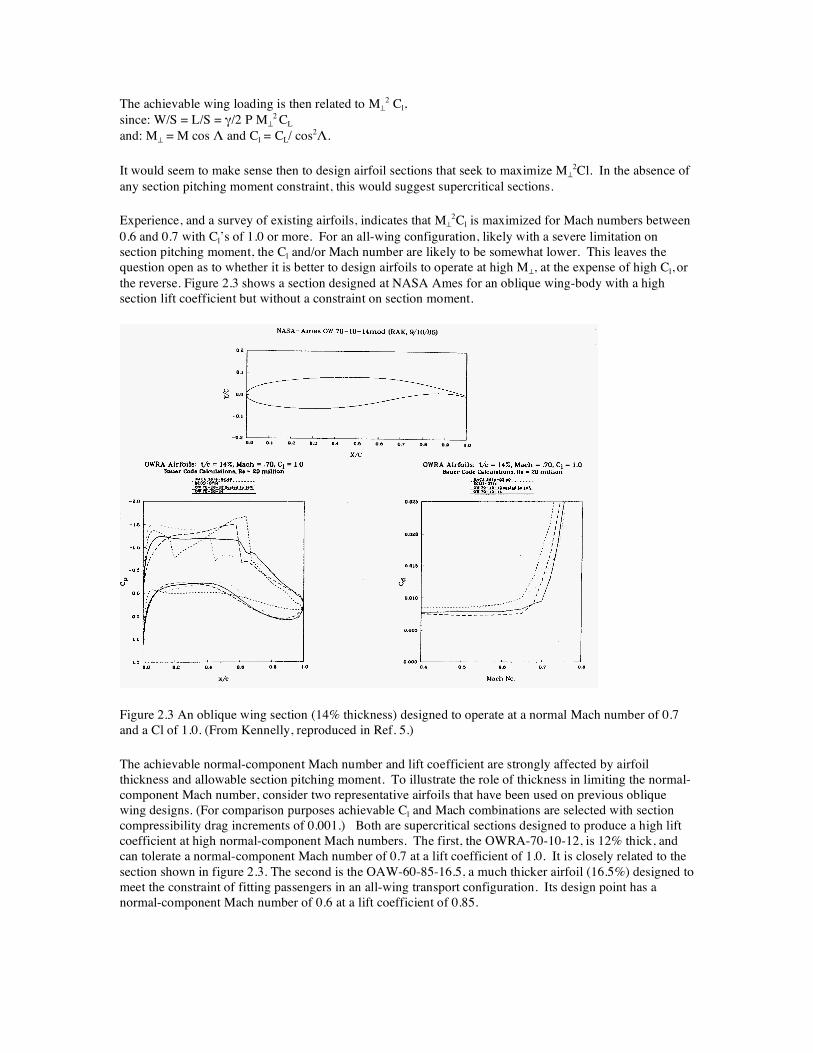
0.6 and 0.7 with Cl’s of 1.0 or more. For an all-wing configuration, likely with a severe limitation on section pitching moment, the Cl and/or Mach number are likely to be somewhat lower. This leaves the question open as to whether it is better to design airfoils to operate at high M⊥, at the expense of high Cl, or the reverse. Figure 2.3 shows a section designed at NASA Ames for an oblique wing-body with a high section lift coefficient but without a constraint on section moment.
Figure 2.3 An oblique wing section (14% thickness) designed to operate at a normal Mach number of 0.7 and a Cl of 1.0. (From Kennelly, reproduced in Ref. 5.)
The achievable normal-component Mach number and lift coefficient are strongly affected by airfoil thickness and allowable section pitching moment. To illustrate the role of thickness in limiting the normal-component Mach number, consider two representative airfoils that have been used on previous oblique wing designs. (For comparison purposes achievable Cl and Mach combinations are selected with section compressibility drag increments of 0.001.) Both are supercritical sections designed to produce a high lift coefficient at high normal-component Mach numbers. The first, the OWRA-70-10-12, is 12% thick, and can tolerate a normal-component Mach number of 0.7 at a lift coefficient of 1.0. It is closely related to the section shown in figure 2.3. The second is the OAW-60-85-16.5, a much thicker airfoil (16.5%) designed to meet the constraint of fitting passengers in an all-wing transport configuration. Its design point has a normal-component Mach number of 0.6 at a lift coefficient of 0.85.

The role of section pitching moment will be discussed in more detail, but it is worth noting here that the strong aft loading typical of modern supercritical sections does offer a significant increase in achievable lift coefficient and Mach number. For example, the OWRA-70-10-12 airfoil has a Cm0 = -0.25 and achieves a value of M⊥
2Cl = 0.49. A typical subsonic transport airfoil, the DSMA 526, is about 11% thick but has a Cm0 = -0.07 and produces a Cl = 0.8 at a normal-component Mach number of .65, for a value of M⊥
2Cl = 0.34 .
Typical transonic airfoil design points are selected so that the transonic wave drag is not zero, but is not so high as to reduce the aircraft performance or economics. The selection of an acceptable section wave drag is complicated in the case of highly swept wings by the fact that the section wave drag acts perpendicular to the isobars and so the net effect on wing drag is:
CD = Cd * cos3Λ.
It appears, therefore, that one might push the section to operate much higher into drag rise than is typical for wings at more moderate sweep angles. However, other factors influence the selection of sweep angle to maximize performance at supersonic speeds. This requires consideration of three-dimensional characteristics, not included in simple sweep theory.
2.2 Beyond Simple Sweep Theory – Three-Dimensional Effects on Oblique Wing Aerodynamics
Three aspects of 3-D wing aerodynamics important to oblique wing design are discussed here:
1. The effect of finite span on optimal sweep through 3D lift-dependent drag. 2. The classical effect of sweep on the wing lift distribution. 3. A significant effect of the wing spanwise thickness distribution (volume) in supersonic flow.
2.2.1 Finite Span Effects on Oblique Wing Performance
As noted in Chapter 1, the yawed ellipse represents an intriguing solution for minimum lifting drag with an elliptic distribution of area in both the spanwise and streamwise directions. A symmetrically-swept planform with the same span and length may also be created with an elliptical distribution of area in the spanwise and streamwise directions as shown in figure 2.4. Although the symmetrical design with the same span and length can achieve the same lift-dependent drag at low supersonic Mach numbers, it requires higher sweep and smaller chords for a given span, length, and area. This has adverse implications for viscous drag, structural weight, and internal volume, but the higher sweep and lower normal Mach number allow thicker sections, which offset these disadvantages.
Figure 2.4. For minimum drag, lift must be distributed elliptically over the span and length of the planform. The above figure shows two solutions from an interactive "game" for supersonic wing designers (Ref. 4).

The optimal span and length are fundamentally features of the three dimensional character of the wing and are directly related to the selection of the optimal sweep, emphasizing that the optimal sweep may not be chosen solely on the basis of infinite wing simple sweep theory. Increasing the sweep angle above that needed to keep M^ below drag divergence increases the section Cl, but also increases effective length. An interesting trade-off arises between the benefit of increased length in reducing the lift-dependent and volume-dependent wave drag and the benefit of decreased sweep to increase span, decreasing the vortex drag. A further complication arises in that the wave drag depends on the distribution of lift and volume computed from a set of oblique cuts through the geometry at many different roll angles. So, although the simplest theory that applies near Mach 1 suggests that the two geometries in figure 2.4 would have the same lift-dependent wave drag, substantial differences exist above Mach numbers of even 1.4 and it is necessary to specify planform details to provide an accurate account of these more complex 3D effects.
One approach to investigating these trade-offs to determine the best wing sweep as a function of Mach number is to perform a series of optimizations using a realistic wing drag build-up model. Such a model for oblique wings consists of a sum of skin friction drag, airfoil section compressibility drag, classical finite-wing induced drag, and supersonic lift-dependent and volume-dependent wave drag. A more detailed discussion of how each of the drag components are modeled in such a drag build-up model is included in Appendix A.
This drag model was used to determine the sweep angle for best L/D at a series of Mach numbers. The series of figures that follow illustrates the combination of Mach number, sweep angle, and lift coefficient for best L/D for a wing with aspect ratio = 12, airfoil t/c = 0.12 and airfoil pitching moment (Cm0) equal zero.
Figure 2.5 shows the resulting optimum L/D vs. Mach number. Figure 2.6 shows the optimal sweep vs. Mach number. Figures 2.7 and 2.8 show the normal-component Mach number and lift coefficient, respectively, vs. Mach number.
The optimization process finds best performance with more sweep than would be indicated from consideration of section properties alone. This is illustrated by the solution at Mach 1.4, which yields an optimum sweep of 64.5 degrees resulting in a normal-component Mach number of 0.6 and an average section Cl=0.7. At this condition, the 2-D section compressible drag component is only 0.0004, the induced drag component is 0.0029, and the L/D is 12.1. By comparison, if the sweep of the wing was reduced to 62 degrees while fixing CL, the airfoil section would be at drag divergence with a section Cl= 0.6 and a normal-component Mach number of 0.66. The 2-D section compressible drag component increases to 0.001, the induced drag component is 0.0024, and the L/D is 11.9. As the sweep is increased from 62 degrees to 64.5 degrees, the decrease in section drag is largely offset by the increase in induced drag, but the volume-dependent wave drag on the wing also drops from 0.0014 to 0.0010 leading to an improvement in L/D.
Although a 2.5-degree change in wing sweep might seem insignificant, note the substantial change in normal-component Mach number and section Cl. Based on the results in Figures 2.5-2.8, it appears that the tendency to fly at higher sweep than would be expected based on 2-D section performance becomes even greater at higher Mach numbers. At Mach 1.8, the optimum normal-component Mach number has dropped to 0.52, with a section Cl=0.82, well below drag divergence for the 2-D section. The challenge then becomes obtaining such high design lift coefficients with constraints on pitching moment and with 3D viscous effects.

Figure 2.5. L/D vs. Mach number with optimal sweep for AR=10, t/c=0.12 wing
Figure 2.6. Sweep vs. Mach number for best L/D for AR=10, t/c=0.12 wing

Figure 2.7. Normal-component Mach number for best L/D for AR=10, t/c=0.12 wing
Figure 2.8. Normal-section Cl for best L/D for AR=10, t/c=0.12 wing

2.2.2 Effect of Oblique Sweep on Spanwise Lift Distribution
A well-known effect of wing sweep is the variation of induced downwash along the span from the trailing wake that produces an additional lift distribution characterized by increased loading on the aft wing and reduced additional lift on the forward wing. For a wing with no twist or bend, this results in a significant rolling moment, tending to roll the forward wing downward. There is also a yawing moment from the asymmetrical distribution of induced drag that tends to unsweep the wing. These moments scale roughly linearly with CL until the onset of flow separation on the wing.
Naturally the wing needs to be appropriately twisted (or bent) so that the basic lift distribution combined with the additional lift distribution at the cruise CL results in a more-or-less symmetrical lift distribution (at least, one that has zero net rolling moment). It turns out that parabolic bend of the wing along its structural axis is especially useful for achieving roll trim. The combination of bend and sweep has the effect of increasing the angle of attack of the forward wing, and reducing the angle of attack of the rearward wing. To illustrate the effect of wing bend, sample cases were run with a vortex-lattice model of an aspect ratio 6 oblique wing with 45 degrees sweep. Wing bend was simulated by adding dihedral to the outboard 50% of each wing panel. The vertical displacement of the wing tip has been referenced to the wing span. These results are shown in figure 2.9.
In addition to designing the wing to have an appropriate deflection under 1-g loading to provide roll trim in this way, it is also possible to design the elastic stiffness of the wing so that increased g-loading due to gusts or maneuvers will cause the appropriate additional bend to trim the additional rolling moment. If, for various reasons, the wing is stiffer than needed to provide this passive trim benefit, it must be recognized that the additional loading on the aft wing will aggravate any tendency toward buffet or separation there. If aileron deflection is used to re-trim the rolling moment of the wing at the higher CL, the localized de-cambering of the section may also aggravate the section to stall. A well-designed oblique wing with reasonable gust/maneuver margins thus must have somewhat greater buffet (stall) tolerance on the aft wing than might be assumed from simple 2-D arguments.
Figure 2.9. Wing Bend Required to Maintain Roll Trim at Various Lift Coefficients for an Aspect Ratio = 6 Wing at 45 Degrees Sweep. (Low speed.)

2.2.3 Additional 3D Effects on Oblique Wing Aerodynamics
The other significant aspect of the finite oblique wing characteristics arises from the supersonic spanwise flow. Normally when simple sweep theory is applied, an argument is made that the spanwise flow component has an insignificant effect on the wing pressures. However, for a finite-span oblique wing with a supersonic spanwise flow component, this effect becomes substantial, and strongly influences the section pressure distributions at various locations on the wing.
Consider an equivalent slender body with the same cross-sectional area variation along the span as the oblique wing, operating at a Mach number corresponding to the spanwise Mach component. Figure 2.10 illustrates a typical pressure distribution over such a body. This pressure distribution represents a variation in the local pressure field that each 2-D airfoil section is immersed in.
Figure 2.10. Equivalent slender body pressure distribution in supersonic flow.
It is evident that the forward wing is immersed in a local flow field that is compressed somewhat above freestream pressure, and somewhat below freestream Mach number. This results in a more benign flow environment than would be anticipated from simple 2–D analysis. At the same time, the rear wing is immersed in a local flow field with accelerated flow, higher local Mach number and lower local pressure. This has the effect of raising the (negative) Cp on both the upper and lower surface, so that although the section lift coefficient may be the same, the shock Mach number is higher and there are more strongly adverse pressure gradients on both the upper and lower surface. These effects are shown schematically in Figure 2.11 and in computational results in Figure 2.12. The CFD results show the wing colored based on Cp and the Cp distribution at several chordwise sections. The acceleration of the spanwise flow is particularly evident in the color change over the slope discontinuity on the wing at mid span.
Figure 2.11. Schematic illustration of effect of spanwise flow component on section Cp distributions on forward and aft wings.

Figure 2.12. Euler CFD Solution on an AR=10 oblique wing swept 65 degrees at Mach 1.6. Note that the Cp distribution on the forward and aft wings is very different even when twist or bend is adjusted to maintain roll trim. Cp is shown along normal cuts at 4 spanwise locations.
2.3 Center of Gravity Location, Supercritical Airfoils, and the Effect of Section Pitching Moment
A challenging aspect of all-wing configurations is the packaging of payload, systems, engines and structure to achieve a center of gravity in the desired location. Locating the center of gravity forward of the 25% MAC point may be difficult from a packaging standpoint, but leads to a statically stable vehicle with simpler control system requirements. However, pitch trim with the c.g. so far forward requires airfoils with nearly zero or positive section pitching moments.
Conversely, exploiting the useful internal volume to contain payload and systems is likely to lead to a rather aft c.g. location. This allows airfoils with moderately negative section pitching moment that may provide a performance benefit compared to the airfoils required to trim with a forward c.g.. A practical constraint on aft c.g. location may arise, not only from stability requirements, but also from controllability requirements. The incremental (added) lift resulting from a trailing-edge flap deflection typically has an effective center of pressure at about 40% chord. As the c.g. is moved aft toward the 40% chord location, the incremental pitching moment produced by the flap deflection diminishes to zero.
Ignoring the packaging, stability, and controllability requirements for the moment, it is worthwhile to explore the performance tradeoffs with respect to c.g. location by enabling more aft-loaded (supercritical) airfoils to be used. Based on the previous discussion, one may anticipate that supercritical sections would tend to reduce sweep at a fixed lift coefficient. This should improve performance at subsonic cruise conditions where the increased span is clearly beneficial. For supersonic cruise, the previous discussion suggests that the benefit would not be realized, since the optimal sweep increases to reduce the lift- and volume-dependent wave drag.
To study the tradeoffs affecting performance as c.g. location is changed, the wing drag build-up model previously described was incorporated into a vehicle performance/mission analysis program developed by Desktop Aeronautics. This program includes a structural weight model, engine performance model,

available fuel volume constraint, and other operational constraints. The effect of section pitching moment on the airfoil compressibility drag was modeled by linear interpolation between conventional sections and the supercritical OWRA-70-10-12 airfoils described previously. This simple model correlates the airfoil section pitching moment to the drag divergence Mach number at a given lift coefficient.
The center of gravity location was varied parametrically for a family of oblique all-wing vehicles optimized for a particular mission. As an illustration of the mission analysis and design program's optimization capabilities, airplanes were optimized for maximum cruise range with fixed take-off gross weight and fixed payload. Wing aspect ratio, t/c, and proportion of wing available for fuel tanks were fixed. Oblique wing sweep, wing area, thrust, and cruise altitude were allowed design variables, while pitch trim, climb gradient at cruise, and fuel volume constraints were imposed. The pitch trim constraint determined the required airfoil section Cm0 for each specified c.g. location. The climb gradient constraint effectively determines the required engine size depending on the cruise altitude, while the fuel volume constraint effectively limits the range for a given wing area. The design optimization was repeated for several c.g. locations, expressed in the form of static stability margin.
The results of this study are shown in figures 2.13 and 2.14. Figure 2.13 shows the L/D vs. cruise Mach number, and figure 2.14 shows the optimum wing sweep vs. Mach number. It is evident that, as expected, for subsonic cruise, there is a small performance advantage for designs with the c.g. located further aft. At Mach 0.85, a c.g. shift of 10% of the MAC, from s.m. = 0.02 to –0.08, decreases the optimal sweep 1.2 degrees and the L/D improves from 21.2 to 21.6. However, at supersonic cruise conditions, there is essentially no change in the optimal sweep or L/D associated with the c.g. shift. It should be noted that the curve for a static margin of –0.18 in these figures represents a c.g. location that violates the controllability constraint described above. Even with this extreme aft c.g., there is no performance benefit; in fact the L/D is lower for the aft c.g. cases at lower supersonic Mach numbers. This indicates that characteristics other than the airfoil section moment (and associated drag-divergence Mach number), are determining the optimum cruise configuration.
Figure 2.13. L/D vs. Mach number for vehicles optimized for maximum range.

Figure 2.14. Optimum Sweep vs. Mach number for vehicles optimized for maximum range.
2.4 Planform Design Features
The next step in oblique wing design involves more than setting the oblique sweep. Many planform design variables can play an important role in oblique wing performance, stability, and control. A few of the more significant parameters are described in this section.
2.4.1 Symmetric Sweep
The influence of the spanwise supersonic flow that increases the effective Mach number of the aft wing motivates the idea of introducing symmetric sweep in the wing planform, so that, combined with the oblique sweep, the aft wing is at a higher sweep angle than the forward wing. A small amount of sweep is introduced by lofting the wing with various chord-fractions located on a straight line. For example, a wing that is lofted with a straight leading edge has forward sweep compared with a wing that is lofted with a straight quarter-chord. A second potential advantage of symmetric sweep is in adjusting the location of the aerodynamic center relative to a fixed c.g. position. This may aid in trim and/or allow selection of a different airfoil section Cm0.
To evaluate the influence of symmetric sweep, four wing planforms (with an unusual wing tip shape, to be discussed later) were lofted with x/c = 0., 0.25, 0.4, and 0.55 fractions as straight lines. Each case was computed with the Cart3D Euler code at Mach 1.6 and 65 degrees of sweep at a CL = 0.18. Based on the results shown in figure 2.14, this is a somewhat aggressive flight condition, so the wings with unswept leading edges and quarter chord lines (x/c=0 and x/c=0.25) were also run at Mach 1.4. Each wing incorporated parabolic bend, adjusted to produce roll trim. Figure 2.15 shows the Cp distributions on the wing upper surface for each of the wings. The effect of symmetric sweep on the pressure distribution at 80% semispan on the aft wing is shown in figure 2.16 for the four wings at Mach 1.6. It is evident from both figures that increasing the symmetric sweep reduces the effective Mach number, so the shock occurs farther forward, although for the Mach 1.6 cases, the Cp at the shock is about the same. Symmetric sweep

also reduces the effective sweep of the forward wing, resulting in changes in the normal-section pressure distributions. In particular, the leading-edge suction peak present on the forward wing with the straight leading edge is suppressed as the symmetric sweep is increased. Bearing in mind that a complete design process would involve tailoring the airfoil shapes on the forward and aft wing to achieve more desirable pressure distributions, the purpose here is to show the sensitivity of the pressure distribution to subtle changes in planform shape.
There is a modest effect of this symmetric sweep on L/D, as shown in figure 2.17, but a more interesting effect is the change in yawing moment. Although there is a modest L/D penalty associated with the reduction in yawing moment, this effect of (negative) symmetric sweep may still provide a means of establishing yaw trim. Based on the results at Mach 1.6, it was hypothesized that the yawing moment is influenced by the spanwise distribution of normal-section pressure drag. As the aft-wing sweep is reduced, the airfoils in that region produce more wave drag and a corresponding negative yawing moment, offsetting the natural positive yaw moment (which arises from the spanwise distribution of induced drag). To test this hypothesis, the unswept x/c = 0 and x/c = 0.25 wings were run at Mach 1.4, where the normal-section pressure drag should be greatly reduced. It seemed reasonable then to expect that the trend of reduced yawing moment with reduced symmetric sweep would vanish.
Figure 2.15. Upper Surface Cp Distribution at Mach 1.6 on Wings with Straight x/c=0 line (upper left), Straight x/c = 0.25 line (upper right). Straight x/c = 0.4 line (lower left) and Straight x/c = 0.55 line (lower right).

Figure 2.16. Normal-section Cp Distributions at Mach 1.6 At 80% Semi-Span on the Aft Wing with Varying Symmetric Sweep.
Figure 2.17 shows the expected increase in L/D as Mach number is reduced from 1.6 to 1.4, due to a substantial reduction in normal-section pressure drag. However, as shown in figure 2.18, the slope of the yawing moment change with sweep was unchanged. Figure 2.19 shows the normal-section Cp distributions at Mach 1.4 at 80% semi-span for these two wings. It is evident that there is still a shock present, although the normal-component Mach number at the shock is only M^ = 1.09, compared with M^ = 1.32 for the Mach 1.6 cases. The wing with unswept x/c = 0.25 line shows a lower Cp value at the shock as well as a farther forward shock location. Nevertheless, it seems unlikely that there would be sufficient wave drag at this section to account for the trend in yawing moment.
Figure 2.17 Effect of Symmetric Sweep on Inviscid L/D

Figure 2.18. Effect of Symmetric Sweep on Yawing Moment.
Figure 2.19. Normal-section Cp Distributions at Mach 1.4 At 80% Semi-Span on the Aft Wing with Varying Symmetric Sweep.

2.4.2 Asymmetric Taper
Another design option to address the issue of the aft wing operating at a higher effective Mach number is to make the planform asymmetrical with a more highly tapered forward wing and less taper on the aft wing. This increases the local chord length on the aft wing, thus reducing the section lift coefficient for the same lift, and reducing the section t/c (assuming the physical thickness is maintained). Both these changes should help reduce the shock strength on the aft wing.
To illustrate the effect of asymmetric taper, the AR=10 trapezoidal wing used to study symmetric sweep was modified by increasing the taper on the forward wing to a taper ratio of 0.4 and decreasing the taper on the aft wing to a taper ratio of 0.6. The t/c of the defining airfoil sections were modified by the same amount so that the physical thickness would be preserved. Figure 2.20 shows the upper surface Cp distribution at Mach 1.4 for the baseline wing and the wing with asymmetric taper. Although it is evident that the asymmetric taper was successful in reducing the shock strength on the aft wing, it also increases the leading edge suction peak on the forward wing. The L/D of this wing is actually slightly lower. Once again, a more refined design process would involve tailoring the airfoil sections to achieve more desirable pressure distributions on both the forward and aft wings.
Figure 2.20. Effect of Asymmetric Taper on Upper Surface Cp Distribution, Mach 1.4. Left: symmetric taper ratio = 0.5, L/Dinviscid = 18.45, Right: asymmetric taper = 0.4/0.6 L/Dinviscid = 18.39
These studies of symmetric sweep and asymmetric taper demonstrate the complexity of oblique-wing aerodynamic design and the need for a complete three-dimensional aerodynamic shape optimization to achieve a satisfactory wing design.
2.4.3 Wing Tip Shape Study
The wing tips of an oblique wing see a variety of flow conditions as the wing sweep is varied. The side edge of the forward tip becomes a leading edge with diminishing sweep as the wing sweep is increased. At some combination of sweep and Mach number, a normal tip side edge becomes a supersonic leading edge. Various concepts for modifying the forward wing tip shape based on heuristic arguments have been studied to determine the effect on wing performance, and the results from four different wingtip shapes will be presented here.
The same trapezoidal wing planform described for previous studies, with AR=10, taper ratio=0.5, was used for this tip-shape study. The baseline tip shape was simply the unmodified trapezoidal wing planform.

With 65 degrees of wing sweep, the tip has a supersonic edge swept 25 degrees. Lofting from the 8% thick airfoil at 90% semi-span to the sharp side edge results in a maximum included angle of 6.7 degrees.
Assuming that a supersonic leading edge tip would be undesirable, the second tip has the side edge cut at a 40-degree angle to the normal chord axis. With the wing swept 65 degrees, the tip side edge is now also swept 65 degrees, resulting in the same subsonic normal Mach number as the wing leading edge. The tip edge is still sharp, and the wing surface was re-lofted by maintaining the maximum physical thickness at the 90% semi-span chord. This increases the included angle of the tip (in the section parallel to the span axis) to about 13 degrees,
A third wingtip shape was formed by maintaining the normal tip edge sweep from the baseline tip, but reducing its length by aggressively tapering the wing trailing edge. The trailing edge was trimmed on a line parallel to the freestream intersecting the tip edge at 40% of the original tip chord length. This results in a portion of the wing trailing edge becoming effectively a side edge and maintains the more slender “wedge angle” of the baseline tip. However, the trimmed trailing edge significantly shortens the chord length at the 90% semi-span section, so that airfoil is effectively thickened to a t/c=11%.
The fourth wingtip shape to be studied combines the concepts of the second and third tips, keeping the trailing edge trim line that forms a streamwise edge and trimming the tip edge to have 65 degrees of sweep with respect to the freestream.
The four wingtip shapes described above are shown superimposed in figure 2.21. It is difficult to determine which edges belong to which tips unless the description above is followed. To aid in interpreting the figure, the tips are drawn in different colors. Tip one is drawn in blue and orange, tip two in green and brown, tip three in red, yellow, and orange, and tip four in red and brown.
Figure 2.21. Four Wing Tip Shapes Studied for Oblique Wings.
Each of these tips was analyzed on the same wing at Mach 1.6 and CL=0.18 with the Cart3D Euler code. Tip 1 and tip 4 were also run at Mach 1.4 In each case, the parabolic bend of the wing was adjusted to achieve roll trim about the center chord axis. For this wing thickness, sweep, and CL combination, Mach 1.6 is somewhat too fast, resulting in high 2-D section drag. The Mach 1.4 cases represent a more reasonable flight condition. Table 5 provides the inviscid L/D results for each wing tip.

Tip L/D @ M=1.6 L/D @ M=1.4
1 14.25 18.45
2 13.79 --
3 13.67 --
4 13.66 16.91
Table 5 Results of Wing Tip Shape Study
It appears that all of the alternate wingtip shapes result in lower L/D than the simple baseline tip. There are two likely explanations for this result. The second and third tip shapes reduce the effective wingspan, the third more so than the second. The second tip also has a blunter included angle as a result of the wing lofting. The fourth tip suffers from both the span reduction of the third tip, and the blunting effect of the second. The trend of reduced L/D seems to correlate more strongly with the reduction in effective wingspan, with bluntness as a secondary effect. Because of the highly swept tip edges, the reduction of effective span is likely to be even greater than would be predicted based only on geometry. At even modest angles of attack, the sharp, highly swept side edge of tips two and four will form a leading-edge vortex sheet that will roll up to initiate the forward tip vortex. The trajectory of this vortex will thus be displaced somewhat inboard from the extreme lateral extent of the tip. The overly aggressive Mach 1.6 flight condition seems to reduce the relative importance of the tip shape, with only a 4% drop in L/D for tip 4 relative to tip 1. At Mach 1.4 where the 2-D section drag is much lower, tip 4 reduces the L/D over 8%.

3. Trim, Stability and Control Issues To aid in conceptual understanding and discussion of the unusual aerodynamic characteristics of oblique wings, it is often convenient to refer forces and moments into a coordinate system that is aligned with the principle inertia axes of the vehicle. In this axis system, the y-axis extends along the span, the x-axis points ‘aft’ along the centerline chord, and the z-axis points up, normal to the plane of the wing. In the following discussion of trim, stability, and control, unless otherwise noted, pitching moment will be assumed to be nose-up about the span axis, rolling moment to the right about the chord axis, and yawing moment to the right about the normal axis.
Oblique wings produce rolling moment, yawing moment, and side force that vary as lift coefficient is increased, in addition to more customary lift, drag, and pitching moment variations. Strategies for designing and operating the vehicle for trimmed flight deserve special attention.
To illustrate these trim strategies, an example oblique wing was analyzed with CART3D and the untrimmed forces and moments estimated as shown below. The example wing is shown in figure 3.1. It has an unswept span of 60 ft., a reference area of 360 sq. ft., and a reference chord length of 8 ft.. At supersonic speeds (Mach 1.6), the wing is swept 65 degrees, flies at CL = .18 and incorporates a parabolic wing bend necessary for roll trim at this condition. At Mach 0.8, with 35 degrees of sweep and CL=0.45 the wing is assumed to incorporate the same bending amplitude as in supersonic flight and so is not trimmed in roll without additional control input.
Figure 3.1. Example oblique wing planform for trim strategy evaluation.
In the supersonic case, the forces and moments are summarized below: CL=0.179 CD=0.01305 (L/D = 13.7 inviscid) + .008 (CDp) = 0.021 CY=-.00174 Wind axes moments: Crollw=-.0019 (based on span) Cmw=-.00749 (based on chord) Cnw=.00064 (based on span) Principal axes moments: Croll = Clw cos Λ - Cmw (c/b) sin Λ = 0.0001 (based on span) Cm = Cmw cos Λ + Clw (b/c) sin Λ = -0.016 (based on chord) Note that moments must be referred to common reference length.

3.1 Pitch Trim
Trim about the long axis in pitch may be achieved with elevator deflection, which changes Cm0, or by properly locating the center of gravity. For the sections assumed in this example with almost 0 moment at zero lift, the net pitching moment of -0.0161 may be trimmed by moving the c.g. aft of the reference center (here at 25% chord) by: dx/c = Cm/CL = -0.0161/.1799 = -0.09, which places the c.g. at 34% of the reference chord. Because the character of the pressure distribution is similar at subsonic and supersonic speeds, very little change in trailing edge deflection or c.g. position is required to trim in the subsonic case.
3.2 Roll Trim
Swept wings have a nonuniform spanwise distribution of downwash induced by the trailing wake. For an oblique wing, this results in an asymmetrical lift distribution where the rear wing panel produces more lift. At moderate sweep angles and lift coefficients, it is possible to twist the wing to produce a symmetrical lift distribution. However, since the degree of asymmetry in the lift distribution is strongly coupled to the wing sweep, the wing twist will only be correct at one sweep angle. A more useful means of making the lift distribution symmetric is to incorporate a small amount of parabolic dihedral (wing bend) into the 1-g wing shape. As the wing is swept, the dihedral has the effect of increasing the incidence on the forward wing, and reducing the incidence on the rear wing. The incidence angle is approximately proportional to the sine of the sweep angle, so a wing can be designed to have a nearly symmetrical lift distribution over a wide range of sweep angles.
As with a twisted wing, an oblique wing with parabolic bend is only perfectly trimmed at one lift coefficient for a given sweep angle. At other lift coefficients, traditional aileron roll control is required to balance the remaining untrimmed roll moment. In addition to designing the wing with the appropriate parabolic bend to provide roll trim under 1-g loading, it is also possible to design the elastic stiffness of the wing so that increased g-loading due to gusts or maneuvers will cause the appropriate additional bend to trim the additional rolling moment. A typical value of wing flexibility to maintain passive roll trim is about 1% of span per ‘g’, based on the example in figure 2.9. Of course, the desired stiffness will change with aspect ratio and other design parameters.
Small changes in rolling moment may also be effected by aileron input. If one assumes, for this example, an aileron geometry shown in figure 3.3, then the rolling moment coefficient (about the centerline chord axis) is estimated as follows:
aileron lift = q Δ Cl (5)(5) cos2Λ
So: rolling moment = q (2) ΔCl (5)(5)(25) cos3Λ = q (.000101)(360)(60) and the rolling moment coefficient is:
ΔCroll = 0.029, which suggests that modest changes in section Cl (and aileron deflection) at transonic conditions are sufficient to produce fine roll trim.

Figure 3.3. Example aileron dimensions.
3.2 Side-force Trim
The aerodynamic forces on an oblique wing include side-force components that are not experienced on symmetrical aircraft. Although the side force is large enough that it cannot be neglected, it is easily trimmed by flying with a small bank angle, on the order of one or two degrees. The side-force has two origins, one resulting from the wake-induced downwash on the lifting vortex system, the other a result of the supersonic wave drag.
When the bound vortex is swept, the induced downwash produces a side force in addition to an induced drag force. An oblique wing with the right tip forward (a standard that has been followed in most studies over several decades) has a positive side force in subsonic flow. This side force is easily trimmed by flying with a small bank angle. In fact, care must be taken in interpreting computational predictions, since most codes vary the angle of attack by rotation about the normal Y axis that produces a wing bank angle as well (the forward tip is elevated with respect to the aft tip). The resulting side-force component of the lift vector overwhelms the induced side force.
Figure 3.4. Side-force trim approach using wing bank.
In supersonic flow, there is also a side-force component from the integrated pressure distribution. This is essentially the volume-dependent wave drag of the wing subjected to the supersonic spanwise flow component. An oblique wing with the right tip forward has a negative side force in supersonic flow.
In the example case, at supersonic conditions, the computed bank angle to trim is:
φ = tan-1 CY/CL = tan-1 (-.00174/.179) = 0.55 degrees
At subsonic conditions the result is still less than 1 degree.

3.3 Yaw Trim
The spanwise distribution of induced drag and 2-D section drag results in significant yaw moments. Of the lateral forces and moments generated by the oblique wing, the yaw moment is perhaps the most difficult to deal with. A fin on the aft wing provides the most natural means of yaw trim, but the lift load (and drag) on a fin located above the wing also produces a pitching moment about the span axis. In the example case here, a single vertical fin with 3% of the wing reference area (10.8 sq ft) located at Y=-25 ft requires a lift coefficient of only 0.057 to trim the residual yawing moment. A second fin on the lower surface cancels the pitch coupling effect, but creates ground clearance problems. An upper surface fin may also be canted so that the line of action of the lift load on the fin passes near the span axis, minimizing the pitch coupling. A fin may be undesirable for other reasons, but the alternatives are not very satisfactory.
Split ailerons, similar to those used on the B-2, are effective at low sweep, subsonic conditions, but loose effectiveness rapidly at high sweep angles.
Figure 3.5. Split ailerons have been considered for yaw trim, but are probably inefficient approaches.
In any case, a relatively large drag penalty would be paid for trimmed flight with the significant split flap deflection needed for trim, not just control and/or stability augmentation. Using 2-D results from Horner (subsonic) with:
ΔCd = 0.6 @ δf=60° (ref to flap area) using aileron geometry in figure 3.3 we find that split aileron deflections of about 30 degrees are required, implying that it is difficult to trim at high sweeps with this approach. Even subsonically, the required deflection is similar.
Engine offset may also be used to produce yaw trim, but at high sweep angles, the required engine offset is large enough to cause problems for low-speed trim.
Figure 3.6. Yaw trim with engine thrustline offset -- example calculations.

An offset of 7.4 ft in the unswept long axis direction is required to trim the example at subsonic speeds.
Multiple engines would be required to allow trim over a range of flight conditions by differential thrust. This requires excess installed thrust. Differential thrust vectoring is also rather ineffective because of the short moment-arm of the off-axis thrust component about the c.g. and any thrust-related trim strategy naturally becomes throttle-dependent.
Figure 3.7. Yaw trim with thrust vectoring -- example calculations.
A cascade of very small fins on the wing upper surface may provide a satisfactory compromise with other design objectives. With a total area of 10 sq ft, the fins shown in figure 3.3 would require a local Cl of only 0.076 to trim the example in yaw at supersonic speeds and a moderate loading of 0.33 at the subsonic condition.
Figure 3.8. Yaw trim with small vertical fins may be compatible with some applications.

3.4 Combined Trim Analysis and Trim Strategy
To aid in rapid trim assessment, an interactive analysis tool has been developed that determines basic trim requirements given a set of untrimmed aerodynamic forces and moments. The inputs can be provided from any source available, such as wind tunnel data, computational methods, or some form of response surface. The wing bank angle for side-force trim, c.g. location for pitch trim, wing bend for roll trim, and fin lift, split flap deflection, or thrustline offset for yaw trim, are all computed and displayed. An example of the graphical user interface for the trim applet is shown in figure 3.9.
Figure 3.9 Screen image of OFW trim applet.
3.5 Effect of Planform Shape and Operational Parameters on Forces and Moments
Because of the large number of possible oblique flying wing geometries and their complex relationship to the vehicle forces and moments, a simplified parameterization of oblique wings with 6-10 parameters (including aspect ratio, symmetric sweep, asymmetric taper, wing bend, angle of attack, and others) was used to generate a response surface model of forces and moments. Results were generated with multiple runs of the A502 surface panel code and checked with selected runs of CART3D. Geometries were generated automatically for both codes with the Desktop Aeronautics RAGE parametric geometry tool. Example results are shown in figures 3.6 and 3.7 for a 65 deg obliquely swept wing at Mach 1.4 with the moment center at the quarter chord of the root section. (taper 0.5, AR 8, symmetric sweep zero at 1/4 chord, CL approx 0.12).

Figure 3.6. Effect of parabolic bend on rolling moment.
Figure 3.7. Effect of parabolic bend on yawing moment.

4. Structural Considerations and Aeroelastic Issues
This section is still in development (ignore for now).

5. Wind Tunnel and Flight Testing of Oblique Flying Wings
5.1 Wind Tunnel Testing Issues
Testing any all-wing configuration presents challenges for supporting the model in the wind tunnel and obtaining force and moment measurements from it. The oblique all-wing concept further aggravates these problems because it has the potential to produce large untrimmed roll and yaw moments, and the lack of flow symmetry causes unusual support system interference, even at zero sideslip angle.
The NASA program of the early 1990’s provides one approach to overcoming these testing issues, despite the fact that the results remain unpublished. Certainly other solutions may also be feasible. The following discussion describes the model support and force balance used in those tests, and addresses various issues and experiences that arose during the tests.
5.1.1 Model Support
The model was mounted in the NASA Ames 9 ft x 7 ft Supersonic Wind Tunnel using a blade strut that attached to the underside of the wing at mid-span. A notional sketch of the support is shown in the figure below. Because of the asymmetrical flow in the region below the wing, the blade was cambered and twisted in an attempt to align it with the local flow, minimizing the lateral load on the blade and resulting influence on the model.
A procedure for designing the strut shape was developed using the TRANAIR full potential CFD code. The oblique all-wing configuration was modeled in the nominal cruise condition with a survey grid of off-body sampling points arranged in the location where the model support blade would be. Local velocity information at these points was used to compute a “warped” stream-surface shape that was everywhere tangent to the local flow. This surface was treated as the mean surface to define the blade support, with a supersonic airfoil (wedge-plate-wedge) thickness distribution added. Once this was done, a second iteration TRANAIR model was run with the blade included. The results of this computation showed that the blade was producing some lateral force, so the local incidence (twist) of the blade was adjusted at several stations and the configuration re-run until there was essentially no lift on the blade. Of course since the blade must have finite thickness, there remained the pressure influence on the lower surface of the wing related to the displacement of the flow around the strut.
It was found during the wind tunnel test that there was a moderate untrimmed roll moment on the model that was suspected of originating from interference from the blade strut. An OVERFLOW Navier Stokes CFD solution of the wing with and without the blade later confirmed that the blade was in fact inducing the rolling moment on the model. These CFD solutions were to be used to generate strut corrections for the wind tunnel data.
One conclusion from these results is that the simple method employed to warp the blade was not adequate. Apparently the pressure field caused by the thickness of the blade influenced the wing differently on the left and right sides. This would be expected given the large wing sweep. Although it is not possible to design a strut that produces no influence on the model, it would be desirable to use an optimization procedure to minimize the induced moments (predominantly roll moment) from the model support system.
5.1.2 Force Balance
The oblique all-wing configuration tested by NASA in 1993 was designed as a passenger transport, so the center region of the wing was fairly thick (about 16% t/c). Even with this rather thick wing, it was

impossible to install a conventional 6-component internal force balance inside the wing. Several arrangements of external balances were studied, but all suffer from requiring extremely large pitching moment capacity that precluded high-resolution drag measurement. Ultimately it was decided to design a special force balance that was arranged as a flat box with a center metric region attached to the non-metric surrounding frame by appropriate gaged flexures. More information on this balance is available from Unitary Wind Tunnel testing organization at NASA Ames Research Center.
5.1.3 Forced Boundary Layer Transition
Three different boundary layer conditions were tested during the NASA OAW tests. The oil-flow interferometry shear-stress measurement technique and traditional sublimation technique were used to determine the presence and location of boundary layer transition. With no forced boundary layer transition, the wing demonstrated a substantial amount of laminar flow. In addition to free transition, two different heights of cylindrical “trip-dots” were tested. The trip dots were 0.040 inch diameter epoxy disks, spaced 0.125 inch apart, following the methodology adopted within the NASA High Speed Research (HSR) program that was proceeding concurrently. Based on traditional boundary-layer trip methodology, an initial trip height of 0.0075 inches was selected. Oil-flow shear-stress measurements found that the 0.007 inch trip height was not sufficient to establish prompt boundary layer transition, and the trip height was increased to 0.011 inches for the remainder of the testing. Unfortunately, some of the test configurations tested with the first trip height were not repeated with the second trip height, complicating efforts to extract useful force and moment increments for those configurations.
It is worthwhile noting here that the same under-estimation of required trip height occurred in the NASA HSR program, where the highly-swept, inboard portion of the wing with a subsonic, rounded leading-edge demonstrated remarkable resistance to boundary layer transition. This may seem counter-intuitive given degree of cross-flow produced by the high-sweep, rounded leading edge. Extensive testing of various trip heights and resulting transition location, as well as an improved method of determining the drag increment from the forced transition is documented in a AIAA Journal article by Aga Goodsell and Robert Kennelly8. The lesson from these studies is to always verify the desired boundary layer transition location as the first objective of testing.

5.2 Oblique Flying Wing Flight Tests
Figure 5.1. Oblique Flying Wing
In order to better understand some of the stability and control issues associated with the oblique flying wing concept an actively controlled low speed testbed was built and flown in 1990 by researchers at Stanford University led by Stephen Morris. This work is described in detail in Dr. Morris' thesis (Ref. 6) as well as in conference papers (Refs. 7-8) available through the links here. A video clip of the flight test at NASA Ames Research Center is also available.
In addition to some of the basic oblique wing design concepts described in Chapter 2 of this paper, the testbed highlighted the importance of thrust/pitch coupling, the influence of vertical surfaces on (long axis) pitch control, the variation in trailing edge control surface effectiveness with sweep (different on forward and aft wings), the non-trivial landing gear design challenges, and the importance of digital lags and latency on a vehicle with short time constants in the long axis dynamic modes.

6. Synthesis, Sizing, and Mission Optimization A series of trade studies for an oblique flying wing of a size and mission capability that might be appropriate for a research aircraft were performed using the aircraft synthesis study code, PASS. The goal of the study was to identify trends and features that emerged as the aircraft was optimized throughout the range of selected Mach numbers.
The baseline mission called for:
• a payload capability of 500 lb • a range of 1,000 n mi • and a takeoff field length (TOFL) of 5,000 ft
These values were chosen to yield a small configuration, but one that might be of sufficient size to introduce challenges in stability and control through coupling of aero-structural deflections and aircraft dynamics.
6.1 Study Description
For the purposes of this study, the following subset of analysis modules was used in conjunction with the integrated optimizer:
Weights The wing weight estimate considers multiple load cases (Takeoff Gross Weight (TOGW), Zero Fuel Weight (ZFW), Taxi). Spars are sized according to bending loads, while non-structural weight is estimated empirically. Empirical estimates are used for control system weights, landing gear and instrumentation.
Drag Viscous drag estimated by equivalent flat-plate skin-friction, and induced drag estimated using conventional advanced design methods. Compressible drag is computed based on expressions from R.T. Jones and JHB Smith for a yawed ellipse.
Engines A rubberized, generic low-bypass turbofan engine model was used for estimating fuel burn and thrust at the given mission segments. Performance is on a par with that feasible by current levels of technology.
Trim No trim drag penalties were modeled. It was assumed that the aircraft CG was located at the root section quarter-chord point at all times, presumably using fuel pumping, or some other balancing mechanism.
Geometry A simplified parameterization was used, and the wing was assumed to be symmetric when the oblique sweep was set to 0. Parameters included:
• Reference area (Sref) • Aspect Ratio (AR) • Symmetric, quarter-chord sweep (Λc/4) • Trapezoidal wing taper (λ) • Break location (η)

• Leading edge extension (LEX) • Trailing edge extension (TEX) • Airfoil t/c • Oblique sweep
Other Takeoff field length estimates are based on an empirical fit related to available thrust, weight, and aircraft stall speed. The stall speed estimate is in turn based on a user-specified value of wing CLmax. Fuel burn used for climb and acceleration to initial cruise conditions is estimated using energy methods.
Baseline aircraft characteristics, along with listings of the design variables and constraints used are summarized below in Tables 6.1, 6.2 and 6.3, while a view of the wing planform is shown in Figure 6.1.
Payload location 0% span
Landing Gear location 25% span
Fuel tank inboard bulkhead 20% span
Fuel tank outboard bulkhead 95% span
Fuel tank chord fraction 75% chord
Fuel tank capacity efficiency 85% of total volume
AR (unswept) 10
Taper ratio (λ) 0.5
LEX* -0.05
TEX* -0.125
Break span (η) 33.3% span
Airfoil t/c 12%
Payload 500 lb Table 6.1 Sizing study aircraft configuration properties *LEX and TEX were defined to produce a constant-chord inboard section.
Figure 6.1 Planform view of study configuration

Design variable Minimum bound
Maximum bound
Oblique sweep (deg) 0.0 90.0
Sref (ft2) 10.0 1000.0
TOGW (lb) 500.0 10000.0
Sea Level Static (SLS) Thrust (lb) 10.0 3000.0
Initial cruise altitude (ft) 30000 65000
Final cruise altitude (ft) 30000 65000
Airfoil t/c 0.05 0.25
Table 6.2 Optimization design variables and associated bounds on values
Constraint Minimum bound
Maximum bound
Initial cruise climb gradient 0.005 -
Final cruise climb gradient 0.005 -
Fuel weight < fuel volume True -
Cruise range (nmi) 1000.0 -
TOFL (ft) - 5000
Table 6.3 Optimization constraints and associated bounds on values
The optimization objective in each case was to minimize the TOGW, unless otherwise noted.
The study consisted of four related configuration optimization cases:
1. TOGW was minimized while airfoil t/c was held constant; the TOFL constraint was disabled for this case.
2. TOGW was minimized while airfoil t/c was varied; the TOFL constraint was disabled for this case.
3. TOGW was minimized while airfoil t/c was held constant; the TOFL constraint was active for this case.
4. Range was maximized while TOGW and t/c were held constant; the TOFL constraint was active for this case.
In each case, the planform parameters (listed in Table 6.1) were held constant. For each study, the configuration was optimized at each of the following Mach numbers: 0.75, 0.85, 0.95, 1.2, 1.4, 1.6 and 1.8. Results computed are presented in the following section.

6.2 Results and Discussion
For all cases, the expected trend of decreasing L/D with increasing Mach number was observed (see Figure 6.2). When considering the closely related cases 1 and 3 (t/c fixed cases with TOGW as objective, with and without a TOFL constraint), differences in supersonic performance are negligible in the Mach 1.2-1.6 range, although there is a discrepancy at Mach 1.8 which is attributed to a poorly converged solution for the case with unconstrained field length (case 1).
For each of the supersonic study cases where a range requirement was set, fuel volume was invariably critical. In the cases where t/c was fixed, the optimizer responded by increasing the wing reference area to accommodate the mission fuel (see Figure 6.3). In the cases where t/c was allowed to vary, it was increased dramatically (see Figure 6.4), while wing area was decreased. Case 4, where the TOGW is fixed and no requirement is placed on range, supersonic performance is somewhat better in the Mach 1.4-1.8 range, no doubt the result of not having the wing size driven by the constraint on fuel volume. This latter case is probably best representative of the L/D values that could ideally be achievable, although as this study illustrates, real-world considerations may make them infeasible. The general increasing trend in required fuel is driven by the interaction between the progressively more powerful engines required to overcome the increase in wave drag with Mach number, and the larger aircraft volume required to fuel these engines.
For cases optimized for sub- and trans-sonic flight, those with a constrained TOFL have lower L/D, which can be attributed to the wing reference areas for these configurations no longer being optimally sized for efficient cruise. Instead, wing reference area is forced to increase in order to decrease the stall speed and thus the TOFL. On the other hand, the unconstrained cases are free to size the wing for optimal wing loading, and in turn have very poor field length performance (see Figure 6.5). It should be noted that weight savings due to changes in the wing structure were largely negligible due to the very small fraction of the TOGW that the wing weight represented.
For the cases with fixed t/c optimized for supersonic flight (cases 1 and 3), the TOFL was never critical. This was likely due to the cumulative effect of having engines sized for supersonic flight (providing ample thrust at the takeoff condition), coupled with the large wing area that resulted from the fuel volume constraint. For the case with t/c as a design variable (case 2), the benefit of increased wing area was lost, since the optimizer in these cases favored the increase of t/c over an increase in Sref.
For the curve of the fixed t/c, TOFL constrained optimization (case 3), the "kink" at Mach 1.2 is the apparent crossing point (apparent, since more points may reveal a smooth curve) between the subsonic curves, where larger wing area is required to meet the TOFL constraint (to lesser degrees as Mach number increases and engine size increases), and supersonic curves, where engine thrust and wing area required to accommodate fuel are such that the TOFL constraint is no longer relevant.
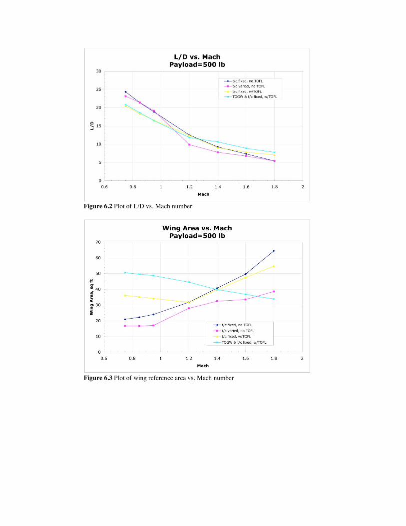
Figure 6.2 Plot of L/D vs. Mach number
Figure 6.3 Plot of wing reference area vs. Mach number

Figure 6.4 Plot of t/c vs. Mach number
Figure 6.5 Plot of TOFL vs. Mach number
From Figure 6.6, it can be seen that the TOGW trends are similar, with each case giving similar TOGW at each Mach number up until Mach 1.4. Beyond this, the results of t/c as a design variable (case 2) have notably lower TOGW than either of the other cases with t/c fixed (cases 1 and 3). It may seem puzzling that a configuration with worse L/D and compressible drag (CDc, see Figure 6.7(a)), and very similar values for induced (CDi, see Figure 6.7(b)) and parasite drag (CDp, see Figure 6.7(c)) appears to result in an ultimately better plane. However, when one considers that the wing areas for this configuration are as small as half the size of the other configurations, it can be surmised that lower absolute drag values (due to a smaller reference area) must be sufficiently low to offset the decreased aerodynamic efficiency of this configuration. The discrepancy between case 1 and 3 is again attributed to a poorly converged solution for case 1 at the Mach 1.8 cruise condition.

Figure 6.6 Plot of TOGW vs. Mach number
(a)
(b)

(c) Figure 6.7 Plots of CDc (a), CDi (b) and CDp (c) vs. Mach number
The trend for oblique sweep, shown in Figure 6.8 below, is fairly consistent among the configurations. As the cruise Mach number is increased, optimal sweep increases in order to keep the wing leading edge behind the oblique shock, and in order to increase the lifting length to decrease wave drag. However, at higher Mach numbers the curves become more shallow as the effective aspect ratio (and hence span) is reduced, resulting in increased induced drag.
Figure 6.8 Plot of oblique sweep vs. Mach number

A plot of normal Mach number vs. Mach is presented in Figure 6.9 below. The general decrease in normal Mach number may be a result of the optimizer seeing more benefit from increasing the lifting length (thus reducing wave drag) rather than maintaining span (and thus keeping induced drag down). The better converged results for cases 3 and 4 indicate that between Mach 1.6 and Mach 1.8, this trend may be reversing, since the normal Mach number is increased in this range. Values for the normal CL vs. Mach (closely tied to the normal Mach number plot discussed above), is shown in Figure 6.10 below.
Figure 6.9 Plot of normal Mach vs. Mach number
Figure 6.10 Plot of normal CL vs. Mach number

The plot of range vs. Mach, only relevant for case 4, is shown in Figure 6.11 below. This serves to illustrate the multi-mission capability of an oblique all-wing aircraft. Depending on the given mission, the same aircraft could fly at Mach 0.75 for 3,500 nmi, or at Mach 1.4 for 1,000 nmi. This is admittedly an idealized example, in that the aircraft wing is being re-sized for each Mach number.
Figure 6.11 Plot of range vs. Mach number

7. Oblique Wing Bibliography 1. Taylor, J., Munson, K., ed. History of Aviation, Crown Publishers, Inc., 1978 (Picture of Blohm and Voss Oblique Wing)
2. Kucheman, D., The Aerodynamic Design of Aircraft, Pergammon Press, 1978
3. Tennant, R., "Super-Sonic Developments", The Aeroplane, Feb.7, 1947
4. Campbell, J., Drake, H., "Investigation of Stability and Control Characteristics of an Airplane Model with a Skewed Wing in the Langley Free Flight Tunnel", NACA Technical Note 1208, May 1947
5. Jones, R.T., "The Minimum Drag of Thin Wings in Frictionless Flow," Journal of the Aeronautical Sciences, Feb. 1951
6. Jones, R.T., "Theoretical Determination of the Minimum Drag of Airfoils at Supersonic Speeds," Journal of the Aeronautical Sciences, Dec. 1952
7. Jones, R.T., "Possibilities of Efficient High Speed Transport Airplanes," Proceedings of the Conference on High-Speed Aeronautics, Polytechnic Institute of Brooklyn, Jan. 1955
8. Jones, R.T., "Aerodynamic Design for Supersonic Speed," Advances in Aeronautical Sciences, Vol.1, Pergammon Press, 1959
9. Lee, G.H., "Slewed Wing Supersonics," The Aeroplane, March 1961
10. Jones, R.T., "New Design Goals and a New Shape for the SST," Astronautics and Aeronautics, Dec. 1972
11. Jones, R.T., Nisbet, J., "Transonic Transport Wings -- Oblique or Swept?" Astronautics and Aeronautics, Jan. 1974
12. Jones, R.T., "The Oblique Wing -- Aircraft Design for Transonic and Low Supersonic Speeds," Acta Astronautica, Vol. 4, Pergammon Press, 1977
13. Jones, R.T., Cohen, D., High Speed Wing Theory, Princeton University Press, 1960
14. Rech, J., Leyman, C.S., "Concorde Aerodynamics and Associated Systems Development," in Case Studies in Aircraft Design, Published by AIAA, 1980
15. Taylor, J., ed., Jane's All the World's Aircraft 1984-85, Jane's Publishing Co. Ltd., 1985
16. Wiler, C., White, S., "Projected Advantage of an Oblique Wing Design on a Fighter Mission," AIAA-84-2474, Nov. 1984
17. Curry, R., Sims, A., "Unique Flight Characteristics of the AD-1 Oblique-Wing Research Airplane," J. Aircraft, June 1983
18. Kulfan, R.M., et al., "High Transonic Speed Transport Aircraft Study," Fional Report, NASA CR-114658, 1973

19. Jones, R.T., Nisbet, J., "Aeroelastic Stability and Control of an Oblique Wing," The Aeronautical Journal of the Royal Aeronautical Society, Aug. 1986
20. Weisshaar, T., Crittenden, J., "Flutter of Asymmetrically Swept Wings," AIAA Journal, Aug. 1976
21. Crittenden, J., et al., "Aeroelastic Stability Characteristics of an Oblique-Wing Aircraft," J. Aircraft, July 1978
22. Weisshaar, T., Zeiler, T., "Dynamic Stability of Flexible Forward Swept Wing Aircraft," J. Aircraft, Dec. 1983
23. Nelms, W., "Applications of Oblique Wing Technology -- An Overview," AIAA 76-943, Sept. 1976
24. Bradley, E., et al., "An Analytical Study for Subsonic Oblique Wing Transport Concept," Fianl Report, NASA CR 137896, 1976
25. BCAC Preliminary Design Dept., "Oblique Wing Transonic Transport Configuration Development," Final Report, NASA CR 151928, 1977
26. Kulfan, J., "Study of the Single-Body Yawed Wing Aircraft Concept," NASA CR 137483, 1974
27. Graham, A., Jones, R.T., Boltz, F., "An Experimental Investigation of an Oblique Wing and Body Combination at Mach Numbers Between .6 and 1.4," NASA TM X-62207, Dec. 1972
28. Graham, A., Jones, R.T., Boltz, F., "An Experimental Investigation of Three Oblique Wing and Body Combinations at Mach Numbers Between .6 and 1.4," NASA TM X-62256, April 1973
29. Hopkins, E., Nelson, E., "Effect of Wing Bend on the Experimental Force and Moment Characteristics of an Oblique Wing," NASA TM X-3343, March 1976
30. Black, R., Beamish, J., Alexander,W., "Wind Tunnel Investigation of an Oblique Wing Transport Model at Mach Numbers Between .6 and 1.4," NASA CR-137697, July 1975
31. Bailey, R., Putnam, P., "Oblique Wing Remotely Piloted Research Aircraft," Presented at 1975 Meeting of the National Assoc. for Remotely Piloted Vehicles, June 1975
32. Andrews, W., et al., "AD-1 Oblique Wing Aircraft Program," SAE Paper No. 801180, Oct. 1980
33. White, S., Beeman, E., "Future Oblique Wing Designs," SAE Paper No. 861643, Oct. 1986
34. White, S., et al., "A Feasibility Design Study for an F-8 Oblique Wing Research Demonstrator," Final Report, NASA Contract No. NAS-11409, July 1984
35. Graham, A., Jones, R.T., Summers, J., "Wind Tunnel Test of an F-8 Airplane Model Equipped with an Oblique Wing," NASA TM X-62273, June 1973
36. Smith, R., Jones, R.T., Summers, J., "Transonic Wind Tunnel Tests of an F-8 Airplane Model Equipped with 12 and 14-percent Thick Oblique Wings," NASA TM X-62478, Oct. 1975
37. Smith, R., Jones, R.T., Summers, J., "Transonic Longitudinal and Lateral Control Characteristics of an F-8 Airplane Model Equipped with an Oblique Wing," NASA TM X-73103, March 1976

38. NASA Ames Research Center, "Oblique Wing Research Aircraft Preliminary Design (RFP)," RFP2-31666, Nov. 1984
39. Smith, J. H., "Lift/Drag Ratios of Optimised Slewed Elliptic Wings at Supersonic Speeds," The Aeronautical Quarterly, August 1961
40. Bauer, F., Garabedian, P., Korn, D., Jameson, A., Supercritical Wing Sections II, Sringer-Verlag, Berlin, 1975
41. Kennelly, R., "Wind Tunnel Test of a 12% Thick High Lift Transonic Airfoil," NASA CR in press, 1986
42. Kennelly, R., "Improved Method for Transonic Design-By-Optimization," AIAA Paper No. 83-1864, July 1983
43. Jameson, T., "Transonic Flow Calculations for Airfoils and Bodies of Revolution," Aerodynamics Rpt. 390-71-1, Grumman Aerospace Corp
44. Gill, P., Murray, W., Pitfield, R., "The Implementation of Two Revised Quasi-Newton Algorithms for Unconstrained Optimization," National Physical Laboratory Rpt. NAC 11, April 1972
45. Stratford, B., "The Prediction of Separation of the Turbulent Boundary LAyer," J. Fluid Mech., Vol. 5, 1959
46. Collins, L., Saunders, D., PROFILE User's Guide, Informatics General Corp. Technical Note No. 11, Nov. 1984
47. Harris, C., "Aerodynamic Characteristics of a 14-Percent-Thick Airfoil Designed for a Normal Force Coefficient of 0.7," NASA TM X-72712, July 1975
48. Sidewell, K., Baruah, P., Bussoletti, J., "PAN AIR -- A Computer Program for Predicting Subsonic or Supersonic Linear Potential Flows About Arbitrary Configurations Using a Higher Order Panel Method. Vol II, User's Manual," NASA CR-3252, 1980
49. Carmichael, R., "A Computer Program for the Estimation of the Aerodynamics of Wing Body Combinations," NASA Ames Research Center, 1969
50. Woodward, F., "Analysis and Design of Wing-Body Combinations at Subsonic and Supersonic Speeds", J. Aircraft, Dec. 1968
51. Arieli, R., Tauber, M., Saunders, D., Caughey, D., "Computation of Transonic Flow About Helicopter Rotor Blades," AIAA Journal, May 1986
52. Mehta, U., "The Computation of Flow Past an Oblique Wing Using the Thin-Layer Navier-Stokes Equations," NASA TM 88317, June 1986
53. Alag, G., Kempel, R., Pahle, J., "Decoupling Control Synthesis for an Oblique-Wing Aircraft," NASA TM 86801, June 1986
54. Burken, J., Alag, G., Gilyard, G., "Aeroelastic Control of Oblique-Wing Aircraft," NASA TM 86808, June 1986
55. Barber, M., DeAngelis, M., Traskos, R., "F-8 Oblique Wing Research Aircraft - A Progress Report," Society of Flight Test Engineers 17th Annual Symposium, August 1986

56. Kroo, I., "The Aerodynamic Design of Oblique Wing Aircraft," AIAA 86-2624, Sept. 1986
57. Morris, S.J., Kroo, I., "Aircraft Optimization with Dynamic Performance Constraints," J. Aircraft, Dec. 1990
58. Phillips, J., "Modal Control of an Oblique Wing Aircraft," NASA TP 2898, Jan. 1989
59. Morris, S.J., "Integrated Aerodynamics and Control System Design for Oblique Wing Aircraft," Ph.D. Thesis, Stanford University, June 1990.
60. Kempel,R., McNeill, W., Gilyard, G., Maine, T., "A Piloted Evaluation of an Oblique Wing Research Aircraft Motion Simulation with Decoupling Control Laws," NASA TP 2874, Nov. 1988.
61. Curry, R., Sim, A., "In-Flight Total Forces, Moments, and Static Aeroelastic Characteristics of an Oblique Wing Research Airplane," NASA TP 2224, Oct. 1984.
62. Curry, R., Sim, A., "Flight-Determined Aerodynamic Derivatives of the AD-1 Oblique Wing Research Airplane," NASA TP 2222, Oct. 1984.
63. Sim, A., Curry, R., "Flight Characteristics of the AD-1 Oblique Wing Research Airplane," NASA TP 2223, March 1985.
64. Van der Velden, A., Kroo, I., "The Sonic Boom of an Oblique Flying Wing," Journal of Aircraft, Jan. 1994.
65. van der Velden, A., Kroo, I., "Aerodynamic Design of the Oblique Flying Wing Supersonic Transport," NASA CR 177552, June 1990.
66. Kennelly, R., Kroo, I., Strong, J., Carmichael, R., "Transonic Wind Tunnel Test of a 14% Thick Oblique Wing," NASA TM 102230, August 1990.
67. Van der Velden, A., Kroo, I., "A Numerical Method for Designing Wings Based on Two Dimensional Pressure Distributions," AIAA Aircraft Design Conference, Sept. 1990.
68. Jones, R.T., "The Flying Wing Supersonic Transport," Aeronautical Journal, March 1991.
69. Tauber, M., Langhi, R., Transonic Rotor Tip Design Using Numerical Optimization, NASA TM-86771, October 1985.
70. Waters, Ardema, Roberts, Kroo,"Structural and Aerodynamic Considerations for an Oblique All-Wing Aircraft," AIAA 92-4220, AIAA Aircraft Design Meeting, August 1992.
71. Seebass, A. R., "The Prospects for Commercial Transprot at Supersonic Speeds," AIAA 94-0017, Sixth Biannual W.F. Durand Lecture, Arlington, VA, May 1994.
72. Galloway, T., Gelhausen, P., Moore, M., "Oblique Wing Supersonic Transport Concepts," AIAA 92-4230, August 1992.
73. Kroo, I., "Tailless Aircraft Design -- Recent Experiences," Ch. 7 of Aerodynamics and Aeroacoustics, K.Y. Fung, ed., March 1993.
74. Sobieczky, H., ed., New Design Concepts for High Speed Air Transport, Springer, 1997.