occupant locating system using restricted detection range in wireless pir sensor...
TRANSCRIPT
Occupant Locating System Using RestrictedDetection Range in Wireless PIR Sensor Network
In Hwan Baek, Xiangrui Liu, and Shubham KhandelwalDepartment of Electrical Engineering, University of California Los Angeles
Henry Samueli School of Engineering and Applied ScienceEmail: [email protected], [email protected], khandelwal d [email protected]
Abstract—Occupant locating plays an important role in manysmart home and smart building applications, such as energyefficient smart work places. Among several techniques proposedfor locating occupants in such an environment is motion sensing-based occupant tracking using PIR sensors. However, the currentPIR sensor-based locating systems have high computationalcomplexity in order to track multiple occupants. Furthermore,they are not easily scalable and the multiple occupant locatingalgorithm must be modified based on the dimension of theroom, number of sensors used, and the sensor placement. Inthis project, we propose an idea to achieve multiple occupantlocating without adding computational complexity as well as toensure easy scalability. Current systems must have probabilisticalgorithm because the overlapping PIR detection regions canbring confusion. In our system, the detection range of PIRsensors are restricted with aluminum so that we can removeundesirable overlapping regions. Our system works as follows:Activity fingerprints are captured by the PIR sensor, which relaysthis information to the Intel Edison through the IR transmittersand receivers. This information is then uploaded to the cloud overWi-Fi by Intel Edison. The cloud hosts a web server and thusa browser can be used to access the web page which shows thelocation of the user in a 2m × 2m section graphically. Extensiveexperiments showed that each subsystem is very reliable.
I. INTRODUCTION
Occupancy detection is used in many buildings to reduceenergy consumption. Occupancy information can be useddirectly by building control systems to reduce the energyconsumption of air conditioning, lighting, IT infrastructure,and other building systems. Occupancy detection can provideinformation to these building systems to allow them to operateproportionally to the number of occupants in the building.For lighting there are potential energy savings of 50% withgood occupancy detection. For HVAC, occupancy driven con-trol could enable energy savings of 20%. Significant energysavings are possible by controlling desktop PC power on andsleep states as a function of usage. This is evidenced by agrowing number of commercial products (for example, [1])and research efforts in this area (for example, [2]). At theheart of these methods is occupancy detection of PC users.
Occupancy detection in current buildings is typically ac-complished using passive infrared (PIR) and ultrasonic motiondetectors. These dedicated occupancy sensors are installedexpressly to determine occupancy and control building sys-tems to reduce energy. Drawbacks to such explicit occupancysensing include limited accuracy, incorrect installation, failureafter installation, and lack of networking capabilities for data
collection. Energy savings from using PIR sensors to controllights can vary from 10% to 45% depending on the type ofroom and the detector settings. PIR sensors are particularly ef-fective for controlling lighting in infrequently occupied closedspaces such as storage rooms, but are ineffective for more openlayouts such as offices. The lack of communication amongthese sensors precludes the sharing of occupancy informationwith other systems and fusion of information from multiplesensors.
In this project we try to address some of these issues.We have tried to redesign some PIR based sensor moduleswhich are energy effective. These efficient modules are thencombined with some unique algorithms which optimize theaccuracy of detection and also help in reducing power con-sumption. In addition to this we make use of Intels low powerplatform called Intel Edison for establishing connectivitybetween various sensors. This helps in sensors exchangingmeaningful data. To help our design be more robust andscalable and to avoid transmission losses we make use ofinfrared communication between PIR sensors and Intel Edisonplatform. Our system also enables use of a remote cloud server.This cloud server receives data from Intel Edison which is thenuseful to display the location of user on a webpage which isuseful for remote monitoring.
II. BACKGROUND AND RELATED WORK
A. PIR Sensor
Every object that has a temperature above perfect zeroemits thermal energy (heat) in form of radiation. Human bodyradiates at wavelength of 9 - 10 m always. The PIR sensors aretuned to detect this IR wavelength which only emanates whena human being arrives in their proximity. The pyroelectricsensor is made of a crystalline material that generates a surfaceelectric charge when exposed to heat in the form of infraredradiation. When the amount of radiation striking the crystalchanges, the amount of charge also changes and can then bemeasured with a sensitive FET device built into the sensor.The sensor elements are sensitive to radiation over a widerange so a filter window is added to limit detectable radiationto the 8 to 12 m range which is most sensitive to human bodyradiation.
B. Abstraction of the Detection Region of a PIR SensorThere are three important properties about detection region
of a PIR sensor. First, the shape of detection region of a PIRsensor is a sector form as shown in Figure 1. Second, the sectorform has a constant radius which is a maximum detectiondistance of the PIR sensor. Third, the sector form also has acentral angle which is a detection range of the PIR sensor.
Fig. 1. Detection region of a PIR sensor
C. Region-Based Tracking AlgorithmFor occupant locating system, PIR sensors are usually used
since they do not require any signal or devices on the occupantto be tracked and they can work in dark environment as well.As shown in the Figure 2, when we use only one PIR sensor,the only information we can obtain is existence of an occupant(technically, the motion of an occupant) within the detectionregion of that one PIR sensor. However, if we deploy twoPIR sensors, we can divide a space into 3 different regions.Therefore, the more PIR sensors we deploy, the more differentregions we can divide a space into, and then the more accurateoccupants location information we can obtain.
Fig. 2. Sensor deployment with only one PIR sensor and two PIR sensors
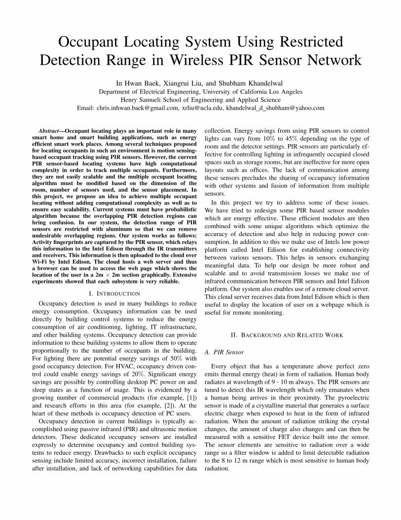
[3] proposed a region-based tracking algorithm that aims tofind out which region an occupant is located by using outputsignals of several PIR sensors. For example, there are thirteendifferent regions in the example of Figure 3. If the outputsignals of the all PIR sensors are high, which means that theyare detecting an occupant in their own detection region, theoccupant is in the center region A of the small room becauseit is intersection of the detection regions of each PIR sensor.Therefore, in general, region-based tracking algorithm can besummarized as calculating the detection regions of each sensorthat detects the occupant and the regions outside the detectionregions of each sensor that do not detect the occupant.
Fig. 3. A possible deployment example for a small room with 4 PIR sensors
However, the region-based tracking algorithm proposed by[3] has a big limitation. Considering the scenario of Figure 3,if one occupant is located in the region A, the output signalsof all PIR sensors are high. But, if one occupant is locatedin the region B and another occupant is located in the regionC in the meanwhile, the output signals of all PIR sensors arealso high. So, the region-based tracking algorithm proposedby [3] cannot figure out whether there is just one occupant inthe region A or there are two occupants in the region B andthe region C in the meanwhile. As a consequence, it cannotlocate multiple occupants.
There have been efforts to solve the multiple occupantstracking problem. [4] proposed multiple target tracking schemeusing joint probabilistic association and consensus filtering.However, this proposed method brings more computationalcomplexity to the region-based tracking algorithm.
III. SYSTEM DESIGN
We propose a system that incorporates region-based motiontracking using PIR sensor network. Our system solves themultiple occupants tracking problem without adding computa-tional complexity. In fact, our system simplifies computationeven further. This is done by removing overlapping detectionregions of PIR sensors and it is described in details in III-A.
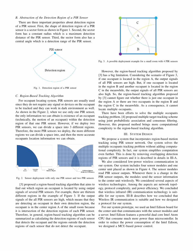
We also considered low-power wireless communication inour system. Our system includes four sensor modules and onecenter unit placed as shown in Figure 4. The sensor modulesread PIR sensor outputs. Whenever there is a change in thePIR sensor outputs, the modules send the sensor informationto the center unit wirelessly. We considered several aspects ofwireless technologies. Among the aspects are network topol-ogy, protocol complexity, and power efficiency. We concludedthat wireless infrared (IR) communication technology is suit-able for our system. III-B describes how we concluded thatWireless IR communication is suitable and how we designeda protocol for our system.
For our system prototype, we used an Intel Edison board forthe center unit that communicates with the sensor modules anda server. Intel Edison features a powerful dual core Intel AtomCPU that consume much more power than microcontoller. Inorder to reduce the power consumption of the Intel Edison,we designed a MCU-based power control.
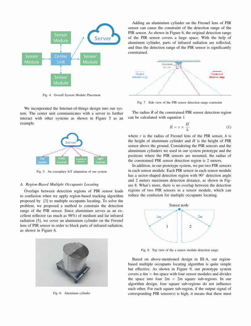
Fig. 4. Overall System Module Placement
We incorporated the Internet-of-things design into our sys-tem. The center unit communicates with a server to furtherinteract with other systems as shown in Figure 5 as anexample.
Fig. 5. An exemplary IoT adaptation of our system
A. Region-Based Multiple Occupants Locating
Overlaps between detection regions of PIR sensor leadsto confusion when we apply region-based tracking algorithmproposed by [3] to multiple occupants locating. To solve theproblem, we proposed a method to constrain the detectionrange of the PIR sensor. Since aluminium serves as an ex-cellent reflector (as much as 98%) of medium and far infraredradiation [5], we cover an aluminium cylinder on the Fresnellens of PIR sensor in order to block parts of infrared radiation,as shown in Figure 6.
Fig. 6. Aluminum cylinder
Adding an aluminium cylinder on the Fresnel lens of PIRsensor can cause the constraint of the detection range of thePIR sensor. As shown in Figure 6, the original detection rangeof the PIR sensor covers a large space. With the help ofaluminum cylinder, parts of infrared radiation are reflected,and thus the detection range of the PIR sensor is significantlyconstrained.
Fig. 7. Side view of the PIR sensor detection range constraint
The radius R of the constrained PIR sensor detection regioncan be calculated with equation 1
R = r × H
h(1)
where r is the radius of Fresnel lens of the PIR sensor, h isthe height of aluminum cylinder and H is the height of PIRsensor above the ground. Considering the PIR sensors and thealuminium cylinders we used in our system prototype and thepositions where the PIR sensors are mounted, the radius ofthe constrained PIR sensor detection region is 2 meters.
In addition, in our prototype system, we put two PIR sensorsin each sensor module. Each PIR sensor in each sensor modulehas a sector-shaped detection region with 90◦ detection angleand 2 meters maximum detection distance, as shown in Fig-ure 8. What’s more, there is no overlap between the detectionregions of two PIR sensors in a sensor module, which canreduce the confusion for multiple occupants locating.
Fig. 8. Top view of the a sensor module detection range
Based on above-mentioned design in III-A, our region-based multiple occupants locating algorithm is quite simplebut effective. As shown in Figure 9, our prototype systemcovers a 4m × 4m space with four sensor modules and dividesthe space into four 2m × 2m square sub-regions. In ouralgorithm design, four square sub-regions do not influenceeach other. For each square sub-region, if the output signal ofcorresponding PIR sensor(s) is high, it means that there must

be occupant(s) in this square sub-region. For example, if theoutput signal of the left PIR sensor in the sensor node 1 is highor the output signal of the right PIR sensor in the sensor node 2is high, there must be occupant(s) in the upper-left square sub-region. Note that here we already achieve 2m × 2m detectionaccuracy theoretically. If higher detection accuracy is required,we can further constrain the detection angle of the PIR sensorsand add more PIR sensors for each sensor node, because in thisway each square sub-region will be further divided into moresmaller regions and thus the detection accuracy is improved.
Fig. 9. The placement of PIR sensor nodes
B. Wireless Infrared CommunicationAs our system consists of wireless sensor network, we
considered low-power wireless communication. There areseveral wireless technologies available and we consideredseveral aspects of these technologies. Among the aspects arenetwork topology, protocol complexity, and power efficiency.Our choice of the network topology is point-to-point becausethe sensor modules directly communicate with center unit.The information sent from the sensor modules only consist ofcommand, module address, and PIR sensor data. Therefore,we do not want huge overhead of extra protocol stacksof Bluetooth or WiFi. Also, we want the sensor module’stransmitter and the receiver to be active only when the PIRsensor outputs change.
We concluded that wireless infrared (IR) communicationtechnology is suitable for our system. Compared to radiotechnologies such as Bluetooth, IR transmitter and receiversare capable of high speed communication at low cost [6].Other advantages of IR over radio are unregulated bandwidth,easy secure implementation, and freedom from multipathfading [6]. Often considered drawbacks of IR communicationdo not affect our system. First, the IR’s difficulty of operatingoutside is not likely a problem because our system is indooroccupant locating. Second, IR’s inability to penetrate throughwalls also means that there is no interference from outsidethe room. Thus, it is much easier to implement secure com-munication. Third, IR communication is direct line-of-sight.
However, our sensor modules and the center unit are mountedon the ceiling and the wall in a room, so we can easily alignthe IR transceivers of each subsystems during the setup.
Our IR communication protocol is based on Sony 12-bitSIRC protocol. The logical ones and logical zeros are formedthe same way as in Sony SIRC protocol, in which a burst of1200µs followed by a space of 600µs forms logical one anda pulse of 600µs followed by a space of 600µs forms logicalzero [7] as shown in Figure 10.
Fig. 10. SIRC Protocol
However, the coded bits carry different information in ourprotocol. Each 12-bit signal consists of three parts. Mostsignificant four bits are the command, the next four bits are themodule address, and the least significant four bits are sensordata as shown in Figure 11 and the information sent as bits foreach type is described in Table I. The bit patterns are designedfor more robust communication. Although it is not likely tohappen, if one bit is misinterpreted and also passed by theSIRC protocol checker, the transmitted signal is ignored asthere is no matching pattern and the receiver requests anothertransmission. Each bit pattern has at least two bits that aredifferent from another within the same type.
Fig. 11. 4-bit IR code
Type Bits DescriptionCommand 1001 Send data
0110 Send ACKAddress 0000 ”Up” sensor module
0101 ”Down” sensor module1010 ”Left” sensor module1111 ”Right” sensor module
Sensor Data 0000 None of sensors on1100 ”Left” PIR sensor on and ”Right” sensor off0011 ”Left” PIR sensor off and ”Right” sensor on1111 Both sensors on
TABLE I4-BIT IR CODE
In order to further improve the reliability of the IR com-munication, we designed a simple two-way handshake asillustrated in Figure 12. When a sensor module has a changein it sensor data, it send a message to the center modulewith ”send data” as the command, its module address, andthe sensor data. Once the center unit receives the message,

Fig. 12. IR two-way handshake
it replies with an acknowledgement, which consists of ACKcommand and the original sensor module address and datareceived. If the sensor module does not receive an ACKmesssage from the center unit, it retransmit the message. Ifthe sensor module receives a message, it extracts the addressand the data and compare them with those in the originalmessage. If there is a mismatch, the sensor module retransmitthe message.
C. MCU-based Power Efficient System
Our prototype uses an Intel Edison board for the center unitas a gateway that communicates with the sensor modules andour server. An Intel Edison is a powerful IoT platform, whichmay suffer from high power consumption compared to ultralow-power microcontroller-based systems.
Acutually, Intel Edison board features an Intel Atom dual-core processor running Linux as its host CPU and a Minute In-tel architecture processor running Viper as its microcontrollerunit (MCU), as shown in Figure 13. The power consumptionof the microcontroller unit is significantly lower than the hostCPU, so we can utilize this feature to reduce the powerconsumption of the Intel Edison board. In order to achieve
Fig. 13. Host CPU and MCU on Intel Edison
the power saving on Intel Edison board, we can have the host
CPU rest in a sleep status while the MCU is kept active tocollect data that comes from four sensor modules and wake upthe host CPU only when the occupants location informationchanges. Figure 14 shows the workflow of our MCU-basedpower efficient system.
Fig. 14. The workflow of MCU-based power efficient system
D. Server Interaction
Our objective is to enable remote monitoring of user lo-cation. Also to enable platform independence we make useof simple web browser based page over which location canbe monitored. Use of web page helps us to remove anydependency on platforms, Operating Systems or softwares.Our solution can be used from tablets, smartphones, laptops,personal computers etc. Communication mechanism used forcommunication from cloud to Intel Edison is secure andencrypted as it uses SSH (secure shell). Also data need touploaded is very minimal and is less than 1KB. This helps usto keep the system power efficient and secure and protected.
IV. SYSTEM IMPLEMENTATION
For our prototype implementation, we used Arduino Unos,an Intel Edison, PIR sensors, IR transmitters, IR receivers, aLinux machine, and other miscellaneous components as shownin Figure 15.
Fig. 15. Overview on system implementation
A. Sensor Module
Our sensor module is implemented with an Arduino Uno,two PIR sensors, an IR emitter (LED), an IR receiver, two

2.7V 400mAh LiPo batteries, and other miscellaneous com-ponents. Figure 16 is our sensor module mounted on a wall.The sensor module base and the housing of the PIR sensors
Fig. 16. Sensor module mounted on wall
are 3D printed. An Arduino-compatible protoshield is used toput all electric/electronic components together.
1) PIR Sensor: In our sensor module prototype, we usedHC-SR501 PIR motion sensor. The output signal of the PIRsensor will be high when it detects human motion. Under therepeatable trigger mode we used, during the delay period,if there are still human motions in its detection region, theoutput signal of the PIR sensor will always remain high untilthe people leave. After the delay period, the output signal ofthe PIR sensor will change from high to low. In additon, weadjust the distance potentiometer on the board to increase thedetection distance to the maximum detection distance (about7 meters) and adjust the delay potentiometer on the board todecrease the delay to the minimum delay (5 seconds).
2) IR Transmitter and Receiver: Each sensor module in-cludes a pair of an IR transmitter and an IR receiver. IRtransmitters are implemented with an IR leds. A PWM signalgenerated by Arduino’s ATmega328 is used to modulate andcode the IR signals. The pin that is mapped to the PWMoutput of ATmega328 cannot supply enough power to theIR LED to achieve the range we need. Arduino Uno’s 5Voutput pin, on the other hand, is capable of supplying enoughpower. Therefore, we connected the IR LED to an N-channelMOSFET, whose gate is connected to the PWM pin as shownin Figure 17.
We used VS1838 38kHz IR receiver to simplify our im-plementation. Although we constraint to use 38kHz carrierfrequency due to its hardware configuration, the line-of-sightnature of IR communication allows us to use 38kHz for allsensor module communication without much interference.
Fig. 17. IR transmitter
B. Center Unit
The center unit is implemented with an Arduino Uno and anIntel Edison connected via GPIO pins as shown in Figure 18.
Fig. 18. Center unit
1) IR Transmitter and Receiver: The center unit needs tocommunicate with four sensor modules and hence four pairsof IR LEDs and IR receivers are installed. The Arduino Unocan only supply one PWM signal for the IR modulation. Thus,four MOSFETs are used as switches to select the IR LED tobe used for transmission as shown in Figure 19.
2) MCU: The MCU API developed by Intel provides aninterface that allows us to control the peripherals that connectto the MCU, and communicate with the host CPU system.In our project, we built an application for MCU using theMCU SDK, an Eclipse-based software development kit whichis used to create applications for MCU on Intel Edison borad.In this application, we use gpio setup API to set up the inputmode for four GPIO ports that are connected to the ArduinoUNO in the center unit and then use gpio read API to readthe value of four GPIO ports all the time. When the value

Fig. 19. IR LED configuration on center unit
of four GPIO ports changes, the MCU can wake up the hostCPU using host send APIs.
3) CPU: Whenever the host CPU on the Intel Edison wakesup, it read the occupant location data from the Arduino Unoof the center unit via GPIO pins. The location data is thenuploaded to the server via SSH.
C. Server
We make use of a file present on the server to maintain thedata needed and use a web browser to parse this data and showthe location of user. Intel Edison is responsible for updatingthe data stored in this file. Intel Edison over Wi-Fi uses SSHand then writes the new data inside this file. A PHP basedweb page, as shown in Figure 20 has been developed whichreads and parses the data from this file. This PHP page alsohas been enabled to auto refresh after every 1 second. Thusthe current user location is updated automatically. Intel Edisonupdates data in server whenever it senses some human motionin the room. This interaction enables real time monitoring ofthe room as well as remote monitoring thus increasing theoverall security feature of the system. The data sent by theIntel Edison on to the server is over a secure shell and thus isencrypted and secure Also very minimal data is needed to besent to the server (< 1 KB)
Fig. 20. Web page that visualizes the occupants location information
V. EVALUATION
Figure 21 shows the indoor experimental setup and corre-sponding divided regions.
Fig. 21. The indoor experimental setup and divided regions
The result of the indoor experiment is depicted in Figure 22Based on our experiment, our system seems to be very accu-
Fig. 22. Result of the indoor experiment
rate. The only problem we encountered is the PIR sensor delay.In other words, the location information may get updated witha delay when an occupant move to another region. The PIRsensor holds the value ”HIGH” for certain amount of time, thusfor a short period of time when an occupant is relocating, thesystem may show that two regions are occupied.
Now, we will also discuss about the evaluation of IRcommunication subsystem. We tested the IR communicationby placing two IR modules separated by two meters, whichis the distance between a sensor module and a center unit.Then, we sent forty messages from one module to the other.For each message, we counted how many transmissions it hadto try until it receives an ACK message from the other andsuccessfully passes the error detection method. The result isgive in Table II. Based on this result, one message needs 1.2transmissions on average until it is successful. Each transmis-sion is done with high speed, so our IR communication systemis fast and robust.

Msg. # of Msg. # of Msg. # of Msg. # oftrans. trans. trans. trans.
#1 1 #11 1 #21 1 #31 1#2 1 #12 1 #22 2 #32 3#3 1 #13 1 #23 1 #33 1#4 1 #14 2 #24 1 #34 1#5 1 #15 1 #25 1 #35 1#6 1 #16 1 #26 1 #36 1#7 1 #17 1 #27 1 #37 1#8 2 #18 1 #28 1 #38 1#9 1 #19 2 #29 1 #39 1#10 2 #20 2 #30 1 #40 1
TABLE IINUMBER OF TRANSMISSION FOR EACH MESSAGE
VI. FUTURE WORK
One of the major concerns about our system is that the IRreceivers are always active and checking for IR signals. Thismay result in unnecessary power consumption. In the futre,we would like to add a photodiode-based IR receiver powercontrol unit for each receiver. Figure 23 shows the designof the power control unit. We can set a threshold value on
Fig. 23. Photodiode-based IR receiver power control unit
the ADC, so a value beyond the threshold indicates strongpresence of IR. Only in the strong presence of IR, we turn onthe receiver.
Another potential improvement is converting our point-to-point Wireless sensor network into wireless mesh sensornetwork. Our prototype works well as it is. However, if ourprototype system is scaled and adapted in a bigger room, weneed to multiple Intel Edison boards as the gateways, eachof which interacts with the server. This may not be the mostcost effective. We may have only one gateway for a room ofany size. If each sensor module directly communicate withthe gateway via IR communication, the power consumption isbe significant. The power consumption is proportional to thesquare of the distance between the transmitter and the receiver.If we use mesh network topology as shown in Figure 24, thepower consumption will scale linearly.
Fig. 24. Wireless Mesh Sensor Network
VII. CONCLUSION
Our developed system has many advantages. The systemuses very basic and power efficient components. The PIRsensor range restriction removes the need of probabilisticalgorithms. Hence the computational complexity is very low.Design is modular and robust and thus is easily scalable torooms of any geometry and size. System does not make useof any wires and thus can be added to existing rooms as wellalong with new construction. Inexpensive components helpto keep the cost of system under $150 including the IntelEdison which can further be used for implementing smartHVAC system. Simple and lucid code helps maintaining andupdating software a trivial operation. Software for cloud isvery simple and is less than 30 lines and does not require anyhigh computation servers. Browser based monitoring of roomhelps in real time monitoring and also platform independenceis maintained. Bandwidth requirement for the system is veryless as < 1KB of data is transferred each time Edison updatesthe data in cloud. In this system we have tried to improve someareas which were not yet explored, thus increasing overallsystem efficiency, power efficiency and cloud interaction.
ACKNOWLEDGMENT
The authors would like to thank Professor Lei He andTeaching Assistant Xiao Shi.
REFERENCES
[1] Aptean.com Verdiem::SURVEYOR, http://www.verdiem.com/surveyor.aspx,2011.
[2] J. Reich, M. Goraczko, A. Kansal, and J. Padhye Sleepless in Seattle NoLonger, Proceedings of the USENIX Annual Technical Conference, June2010.
[3] Byunghun Song, Haksoo Choi, Hyun Su Lee Surveillance Tracking Sys-tem Using Passive Infrared Motion Sensors in Wireless Sensor Network,International Conference on Information Networking, pp.1-5, Jan 2008.
[4] Qi Hao, Fei Hu, Jiang Lu Distributed Multiple Human Tracking withWireless Binary Pyroelectric Infrared (PIR) Sensor Networks, IEEESensors, pp.946-950, Nov 2010.
[5] P. Berdahl Pigments to Reflect the Infrared Radiation From Fire, J. HeatTransfer, pp.355-358, May 1995.
[6] Joseph M. Kahn, John R. Barry Wireless infrared communications,Proceedings of the IEEE,Volume 85, Issue 2, pp.265-298, Feb 1997.
[7] Nhivekar, G. S., R. R. Mudholkar Microcontroller based IR remotecontrol signal decoder for home application, Adv Appl Sci Res,Volume2, Number 4, pp.410-416, 2011.