occurrence and density of shell in the...
TRANSCRIPT

OCCURRENCE AND DENSITY OF SHELL IN THE
VICINITY OF SEVENFOOT KNOLL, MAN O'WAR
SHOAL, SIXFOOT KNOLL AND AREA B
by Robert Cuthbertson
Maryland Geological Survey 2300 St. Paul Street Baltimore, MD 21218
Coastal and Estuarine Geology Program
File Report No. 56
July 1988

TABLE OF CONTENTS
List of Figures.
Page
2
List of Tables. ...... ... . . . .. . . . . . . . . . . . . . .. . . . . ... .. . .. .. . . . . . . ... . . 3
Executive Summary. 4
Introduction. . . . . . . . . . . . . • . . . . . . . . . . . . . . . . . . . . . . . . . . . . . . . . . . • . . . . . 5
Methods . .. ,. • • • ,. • • • • " .. II .. . . ... .. .. .. .. .. .. .. .. .. . II .. .. .. . .. ,. ................. ,. ........... " .. .. 5
Results . .. .. .. . . .. . . .. .. .. .. .. .. .. .. .. .. .. .. .. .. .. .. .. .. .. . . .. .. . . .. .. .. .. .. .. .. . . . .. .. .. .. .. .. .. .. . . .. . . .. .. 15
Sevenfoot Knoll. .... ....... ....... ....... ................ ................. ............ 15
Man 0' War Shoal . . . .. . . . . . . III . . .. . .. .. . .. .. . .. . . . I I .. • .. .. • .. .. .. .. .. .. • • .. • .. .. • • 1 5
Sixfoot Knoll.......... ... .. ........... ............ . .. ........ ... 24
Area B..... .. .......... .. .......... ..... .. ............... .............. .... ......... 24
Discussion.. • • • • • • • • • • • .. • • .. • • • • • .. .. • .. • • • • • • • • • • • • • • • • • • • • • • • • • • • • • • 24
Sevenfoot Knoll. .. . . . . . ... ... ... ... . . . . . . ... . . . . . .. . . ... ... . . . . . . . ... 2�
Man 0' War Shoal............................................ 25
Sixfoot Knoll.. . . . . . . . . . . . . . . . . . . . . . . . . . . . . . . . . . . . .. . . . .. . . 27
Area B .. . . .. . . . ... . . . ...... . . . . . ... . . ..... . . .. . .. . . . . . . . . . . . . . 30
Conclusions. . . . . . . . . . • . . . . . . . . . . . . . . . . . . • . . . • . . . . . . . . . . • • . . • . . . . • . 30
References. • • • • • • • • • • • • • • • • • • • • • • • • • • • • • • • • • • .. • • .. • • • • .. • .. .. • • • .. .. .. .. • • 32
Appendix A
Appendix B
Appendix C
Seismic Data . ..... ... . . . . . ....... ........... . . . . ......... ..... . ...... . . . ..
Core Data ............................................. .. .
Mathematical Calculations . • • • • . • . . • . . . . • • • . • . • . • • • • • . •
1
33
36
70

LIST OF FIGURES
Figure 1. Charts showing proposed areas for seismic subbottom reconnaissance and vibracore groundtruthing. .. .. . . . . .. . 6
Figure 2. Location chart showing coring sites for Sevenfoot Knoll, Man O 'War Shoal and Area B and track lines for seismic subbottom reconnaissance in vicinity of Man 0 t War Shoal.. .. . . . . . . . .. . . . .. .. ... .. .. . .. . . . .. . . . . . 10
Figure 3. Chart showing track lines for seismic subbottom reconnaissance in vicinity of Sixfoot Knoll . . . . . • . . . . . . 12
Figure 4. A contoured chart showing number of bushels of shell per square yard of bottom disturbed for Sevenfoot Knoll, Man O 'War Shoal and Area B ( on surfaces to bottom of shell bearing layer ) .... .. .. ... .. . .. ... .. ... ... ........ 16
Figure 5. Section from seismic record along track line 1 at Man O 'War Shoal ( between LORAN fix marks 1-1 and 1-2) with core #11 location indicated. . . . . . . . . . . . . . . . . . . . . . . . . . . . 18
Figure 6. Section from seismic record along track line 2 at Man O'War Shoal ( between fix mark 5 and end of line ) with core #3 location indicated. . . .. .. . . .. ... . . . . . . . . . . . . ... 20
Figure 7. Section from seismic record along track line 3 at Man O 'War Shoal ( between LORAN fix marks 3-3 and 3-5)...... 22
Figure 8. Section from seismic record along track line at Sixfoot Knoll ( between LORAN fix marks 1-1 and 1-2).... 28
2

LIST OF TABLES
Appendix 1
Table 1. Corrected track line fix marks for seismic subbottom profiles in vicinity of Man O 'War Shoal . • • • • • . • • • . • • • • • . 34
Table 2. Corrected track line fix marks for seismic subbottom profiles in vicinity of Sixfoot Knoll • • • • • • • • • • • • • • • • • • • 35
Appendix B
Table 3. Core logs recorded by the Exmar Company of Norfolk, Virginia............................................. ... 37
Table 4. Corrected core locations • . . . . . . . • . . • • • . . • . • . • . . • . . . . . . • . 64
Table 5. Weight of shell ( g ) for each core section ( shells greater than 1/2 inch ) . .. ........ ... . .. . . ..... . . .. .......... .... 65
Appendix C
Table 6. Mathematical formulas used for calculations in this report............................. ................... .. 71
Table 7. Basic measurements and calculation of pounds of shell per cubic yard of bottom • • • • • • • • • • • • • • • • • • • • • • • • • • • • • • • • 72
Table 8. Calculated quantities of shell )1/2 inch per square yard of subbottom disturbed ( to bottom of shell bearing layer.. ... ............. .. ... .... . ... .. .. . .. .. ...... .... . 73
Table 9. Digitized information from Figure 4 and calculation of amount of bushels for study areas • • . . . • . • • . . . • • • . . . • . • . . 74
3
EXECUTIVE SUMMARY
This study delineated the shell-bearing zones in the subbottom and
estimated the amount of shell present in the areas known as Sevenfoot
Knoll, Man Q'War Shoal, Sixfoot Knoll and Area B. Interpretation of
subbottom records for Man O 'War Shoal and Sixfoot Knoll and vibracore data
for Sevenfoot Knoll and Man O 'War Shoal allowed volumetric estimations of
the quantity of shell. The amount of shell calculated in the vicinity of
Sevenfoot Knoll was 7.56x10⁶ bushels and 94.5x10⁶ bushels in the Man O'War
Shoal area.
4

INTRODUCTION
The objective for the study was to locate areas containing sufficient
shell occurrence and density for the Shell Repletion Program. This is an
ongoing program that supplies shell for the purpose of creating a base on
which oyster spat may grow and therefore new shell resources need to be
discovered for the program to continue. The Fisheries Division, Tidewater
Administration, Department of Natural Resources monitors the progress and
needs of the dredging contractor in supplying shell for this program.
Sevenfoot Knoll, Man O'War Shoal, Sixfoot Knoll, and Area B, northern
Chesapeake Bay, Baltimore and northern Anne Arundel Counties, were chosen
as the most likely areas to contain the amounts of shell required to
fulfill the needs of the program (Figures 1). Investigation of these
areas was performed by the Maryland Geological Survey at the request of
the Fisheries Division. The Survey conducted seismic reconnaissance in the
vicini ty of Man 0 'War Shoal and Sixfoot Knoll and analyzed vibracores
collected by the Exmar Company of Norfolk, Virginia from Sevenfoot Knoll,
Man 0' War Shoal and in Area B east of Man 0' War Shoal.
objectives of this report were:
The specific
(1) to delineate the shell bearing strata in the suggested areas by
analyses of seismic subbottom records and vibracores and
(2) to calculate the volume of shell present for the areas under
study from analyses of the vibracores.
METHODS
In order to accomplish the stated objectives three primary methods
were utilized: (1) seismic subbottom surveying, (2) bottom sampling and
(3) calculated projections of densities and total amounts of shell present
in each of the designated areas.
5

FIGURES 1 . CHARTS SHOWING PROPOSED AREAS FOR SEISMIC SUBBOTTOM RECONNAIS
SANCE AND VIBRACORE GROUNDTRUTHING
6

'B..HHHH 10

39°12'15"
76°20'25"
AREA 8 39°11'20"
76°23'30"
39°11'00"
76°23'30"
MAN O' WAR SHOAL
39°11'00"
76°21'51"
39°10'43"
76°21'40" 76°21'00"
SEVENFOOT KNOLL
39°08'58"
76°23'18" 39°08'53"
76°22'09" �------.:...�
SIXFOOT KNOLL
39°07'57"
76°22'23"
8
39°08'20"
76°21'41"
39°11'08"
76°20'22"

1) Seismic subbottom reconnaissance surveys were conducted in the
vicini ty of Man 0 'War Shoal and Sixfoot Knoll. There were five track
lines followed along the 42xxx LORAN range lines for each of the two areas
(Figures 2, 3). The track lines varied from 350 to 500 yards apart. LORAN
T-O fix marks were recorded at the beginning and end of each track line
and at approximately 900 yard intervals. LORAN T-O coordinates for the
seismic record were corrected in accordance with correction factors
developed by Halka (1987) (Appendix A; Tables 1, 2).
A Oatasonics SBT-220 (5kHz transducer) continuous seismic reflection
system produced acoustic pulses under the water surface directed at the
bottom. The returning signals from the subbottom provided a graphic
record on a chart recorder (EPC model 3200S) of the reflecting horizons
within the subbottom stratigraphy.
Sevenfoot Knoll and Area B, probable shell resource areas, were
omitted from seismic subbottom reconnaissance due to budget and time
constraints.
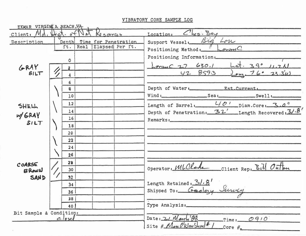
2) Bottom sampling involved the analyses of 25 vibracores collected
by the Exmar Company of Norfolk, Virginia (Figure 2, Appendix B; Table
3). Cores were collected independently of the seismic track lines. Four
cores were collected in the Sevenfoot Knoll area, 20 in the vicinity of
the Man O'War Shoal priority area, and one in Area B. Cores were not
collected in the vicinity of Sixfoot Knoll. LORAN T-O coordinates for the
bottom sample locations were corrected in accordance with correction
factors developed by Halka (1987) (Appendix B; Table 4). The vibracore
barrel length was 40 feet and had a diameter of three inches. The
Tidewater Administration supplied Latitude/Longitude coordinates for the
coring locations, a barge with a crane to lift the coring tower, and the
9

FIGURE 2. LOCATION CHART SHOWING CORING SITES FOR SEVENFOOT KNOLL, MAN O'WAR SHOAL, AREA B AND TRACK LINES FOR SUBBOTTOM RECONNAISSANCE IN VICINITY OF MAN O'WAR SHOAL.
10

390I2'OO'
r'-------------r------------r-----------.-------------,------7r---"""'Tj----,
c HE
II' +
j 10' +
s .AI.
CUlfiHlll tHIUEl fRONT UIII&[ lKHT ."
£>
p E .AI. K E B .AI. y .,.
0,.
C) o
SOL � � 18 �0 += � + -0- ---0- + -:-6-L ---0----. /" .,\ . """"'""EOL 3 EOL 4 0---__ _
�,-�-----'0" 0 � -<>--- � -0 � '0,"
., SOL 4
\.." + +
•
+ ) /.
� �
0
J" 0
0
SOL - START OF LINE EOL - END OF LINE
�S'09'OO' I I , / I, I , ! , I 39"09'00'
1602�'OO' 24 n 22 21 1Iio20'OO' o �oo 1000 YA"OS HE3E3HE3'

FIGURE 3. CHART SHOWING TRACK LINES FOR SEISMIC SUBBOTTOM RECONNAISSANCE IN
VICINITY OF SIXFOOT KNOLL.
12

39°09'00"
,8
o
39°08'00"
()
D
o + +
I� -
I
0-'",,'� '>. "" + ----r.\ SOL 21 76021'41" SOU &- \\ ) --0\ \� -0- --r. roll
+ 39°07'57" •. 76022' �3"
+
SOL 5 0- -0----0 EOL 5
..
I
I
l ________________________________________ ��---------1/ �----------------------�/���----------�(��----------------(���( 39°07'30" I _ _ 76°24'00" 76° 23'00" 76°22'00"
Sixfoot Knoll o 500 1000 YAROS F3 F3 F3 F3 E3
SOL - START OF LINE EOl - END OF LINE
EOL I
tugboat "Big Lou". The cores were cut in sections approximately five feet
in length for ease of transportation and examination. The sections of
each core containing shell were washed through a 1/2 inch sieve using a
Teel centrifugal pump. The 1/2 inch sieve was chosen because the final
shell screen size of a dredge is 1/2 inch. The shells were dried for
several days before weighing. The weight of the shell fraction of each
section of core was recorded (Appendix B, Table 5). No grain size
analyses of the sediments in the vibracores were performed. The
designation of silt in the core logs was reclassed as the general category
mud except when reference was made directly to the core log (Appendix B,
Table 3).
3) The third method of the project correlated seismic subbottom data
with vibracore data for estimates of occurrence and density of shell in
the Sevenfoot Knoll and Man O'War Shoal areas. Estimates of shell
occurrence and density were omitted for the eastern section of the Man
O'War Shoal priori ty area, Sixfoot Knoll and Area B due to insufficient
vibracore information.
The formulas for the calculations of shell volume were reported by
Hobbs (1987) and those formulas along with other calculations are listed
in Appendix C; Table 6. There are two differences, however, between
Hobbs' (1987) work and this report; (1) the size of a bushel and, (2) the
average weight of five gallons of shell. The Maryland bushel is equal to
2800.9 cubic inches (.060 cubic yards) whereas a Virginia bushel is equal
to 3003.9 cubic inches (.064 cubic yards). For volumetric determinations
several five gallon pails containing shell )1/2 inch were weighed. The
average weight of five gallons of shell was 32 pounds. The 32 pounds of
shell per five gallons equals 1293 pounds per cubic yard compared to the
14

28 pounds of shell per 5 gallons or 1084 pounds per cubic yard reported by
Hobbs (1987). The density of shell (pounds of shell per cubic yard of
bottom) determined the quanti ties of shell per square yard of bottom
disturbed for the shell-bearing layer (Appendix C, Tables, 7, 8).
The number of bushels of shell for Sevenfoot Knoll, Man O'War Shoal
and Area B were plotted on a chart at a scale of 1:20, 000, contoured and
digitized using a Hewlett Packard 9825T desktop computer (Figure 4 ) . From
the digitized chart the total number of bushels were calculated (Appendix
C, Table 9).
RESULTS
Sevenfoot Knoll
The four vibracores collected in this area indicated five feet of
soft gray mud overlying a mixed shell-gray mud layer (Table 3). The lower
boundary of the shell bearing layer in each vibracore was delimited by the
presence of coarse sand. The thickness of the shell bearing sediments
varied from 21.2 to 31. 5 feet (Table 5).
Man O'War Shoal
The three seismic subbot tom reconnaissance profiles wi thin the Man
O'War Shoal priority area showed strong acoustic impedence in the first
six feet of bottom sediments (Figures 5-7). The impedence varied
vertically and horizontally throughout the seismic records.
The 20 vibracores collected in this area indicated a mixed shell-gray
mud layer overlying a coarse sand wi th only four cores (111, 2, 5, 7)
containing a gray mud overburden (Table 3). The length of the shell
bearing section varied from 11.5 to 36. 8 feet.
15

FIGURE 4. A CONTOURED CHART SHOWING NUMBER OF BUSHELS OF SHELL PER SQUARE YARD OF BOTTOM DISTURBED FOR SEVENFOOT KNOLL, MAN O'WAR SHOAL AND AREA B (ON SURFACES TO BOTTOM OF SHELL BEARING LAYER).
16

'8 + � a:l + +
cd QI '"' -<
+
�
'<q
� "1:1 a + . +
�
! -
g ..cI G) 00
'"'
� � 0
0
� "::I + + '<q
� �
� --
g '<q � i<1J
� H ..
� � !� +
1� + + � � �
H.< �i ��<1J �i ��
"8 ":c
'n � "s
-
1;
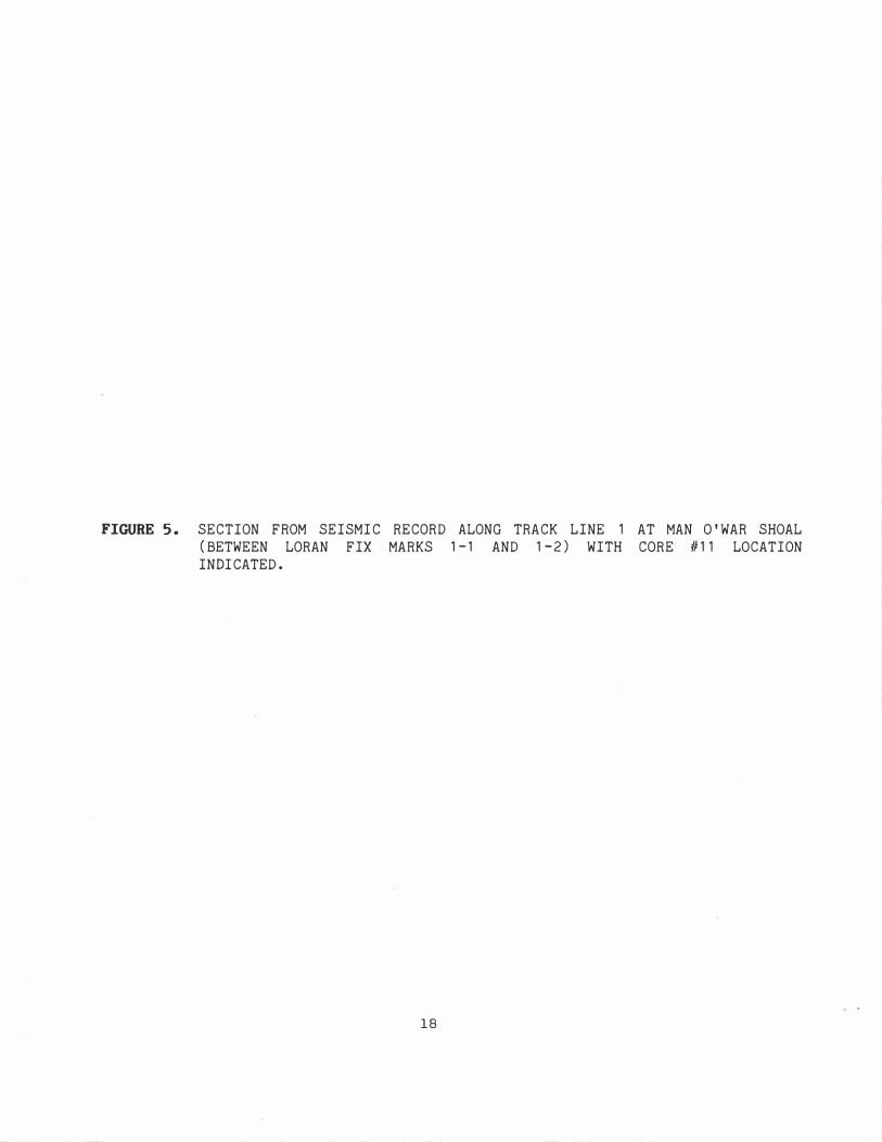
FIGURE 5. SECTION FROM SEISMIC RECORD ALONG TRACK LINE 1 AT MAN O'WAR SHOAL (BETWEEN LORAN FIX MARKS 1-1 AND 1-2) WITH CORE #11 LOCATION INDICATED.
18

� w w �
o
30
60
90
WEST
OUTGOING SIGNAL
'I --
SITE OF CORE #11 SUSPECTED SHELL GRAY SILTY CLAY OVERBURDEN
WATER SURFACE 1 WATER-SEDIMENT INTERFACE MULTIPLE
N I
....
NAVIGATION FIX MARK
a 100 200 300 YARDS r-------,.-------T� _ _ � � -�
EAST
10/6/87

FIGURE 6. SECTION FROM SEISMIC RECORD ALONG TRACK LINE 2 AT MAN O'WAR SHOAL (BETWEEN FIX MARK 5 AND END OF LINE) WITH CORE #3 LOCATION INDICATED.
20

� w w u..
o
30
60
90
WEST SITE OF CORE #3
OUTGOIN G SIGNAL 1
N � C w
NAVIGATION FIX MARK
WATER SURFACE
o
SUSPECTED SHEll
100
WATER-SEDIMENT INTERFACE
. I . . :
I I 1\
200 300 YARDS L--=--: -- _�
EAST
MULTIPLE
Ln I 10/6/87 I
N

FIGURE 7. SECTION FROM SEISMIC RECORD ALONG TRACK LINE 3 AT MAN O'WAR SHOAL (BETWEEN LORAN FIX MARKS 3-3 AND 3-5) .
22

.w w u..
o
30
60
90
WEST SUSPECTED SHELL
GRAY SILTY CLAY OVERBURDEN WATER SURFACE
qI
M
OUTGOING SIGNAL
WATER-SEDIMENT INTERFACE
NAVIGATION FIX MARK
o 100 200 300 YARDS
EAST
MULTIPLE
10/6/87

Sixfoot Knoll
The sections of seismic profiles from track lines 1-4 wi thin the
designated Sixfoot Knoll area showed strong acoustic impedence within the
first six feet of bottom sediments. There were sections present where the
impedence was present at the water-sediment interface.
Area S
One core was taken in this area. The core log showed approximately 4
feet of gray mud overlying a mixture of shell and gray mud approximately
23 feet thick. The shell bearing zone was bounded on the bottom by sand
(Appendix S, Table 3) .
DISCUSSION
Sevenfoot Knoll
The core logs when compared to the sieving analyses present possibly
conflicting data (Appendix S; Tables 3, 4) . The core logs show a layer of
soft gray mud (4-5 feet thick) overlying a layer of shell with soft gray
mud. The sieving analyses shows that shell was present for the first six
feet of bottom (Appendix S, Table 4) . The reason for this discrepancy was
probably due to either visual inspection of the core through the core
liner with the dark gray mud occluding a view of shells, or that the
sieving data was summary data for each section and therefore horizons
could not be delineated.
The shell bearing sediments thickness varied from 21.2 to 31.5 feet.
However, when the weight of shell fell below the 1000 gram level the
densi ty of shell was much reduced. The thickness of shell wi th the
highest densities varied from 16.2 to 26 feet. This suggests that
shellfish colonization was spatially variable.
24

Calculations based on core data indicated there are approximately
453,750 cubic yards (7,562,500 Maryland bushels ) of shell within an area
of approximately 20 8,725 square yards in the vicinity of Sevenfoot Knoll
( Figure 4, Appendix C, Table 9) . This yields an average of approximately
2. 2 cubic yards (36 bushels ) of shell for each square yard of subsurface
material dredged to the bottom of the shell bearing layer.
Man 0 'War Shoal
There were three seismic subbottom reconnaissance profile tracks
conducted within the Man O'War Shoal area. The records from track lines
1, 2, and part of 3 delineated the extent of the shell bearing layer. The
records suggest that a shell resource is present throughout the Man O'War
Shoal area.
interface.
The deposit varies in depth below the water-sediment
To substantiate the interpretation of the seismic record
vibracores were needed. Only two vibracores, #3 and #11 were in
proximity of the track lines to support the seismic interpretation ( Figure
2) •
Track line 1 borders the northern edge of the priority area at Man
O'War Shoal. A strong acoustic impedence ( reflector ) was recorded varying
in depth below the surface of the bottom between 1. 5 and 6 feet as seen in
Figure 5. The strong reflector was interpreted to be a dense shell layer
with a less dense gray mud and shell overburden.
Vlbracore 1111 is located approximately 250 yards east of LORAN fix
mark 2 on track 1. The vibracore log ( Table 3) indicated no presence of
overburden. The weight of shell present in vibracore 1111 ( Table 5) and
the corresponding densi ty ( Table 8) when compared wi th other cores was
much lower for the entire core length. The reduced amount of shell and
increased amount of mud may account for the seismic record at core site 11
25

on track 1. Another possibility is that the overburden on the seismic
record varies rapidly over a short distance and therefore the distance
between vibracore #11 and track
stratigraphic column being recorded.
could account for a different
Track line 2 bisected the r1an 0 'War Shoal. The entire length of
track line 2 indicates a strong reflector at the surface of the bottom.
This was interpreted to be a densely packed layer of shell with a gray mud
matrix. The analysis of vibracore 1t3, located approximately 760 yards
from LORAN fix mark 5 towards the end of the track line (Figure 6) , showed
that the first 28.5 feet of the core was densely packed shell with gray
mud. The reflector present at the surface of the bottom would appear to
indicate the top of the densely packed layer of shell.
Track line 3 borders the southern edge and passes through the eastern
section of the Man O 'War Shoal priority area. The seismic record is
similar to that of track line 1 (Figure 7) . There is a strong reflector
(shell) varying from 1 to 6 feet below the surface of the bottom except
when the track line passes over the shoal area on the eastern end (between
LORAN fix marks 3 and 4) . Here, the strong reflector is present at the
surface of the bottom indicating shell present at the water-sediment
interface. Unfortunately, no vibracore was taken in the vicinity of track
line 3 to substantiate the interpretation of the seismic record.
Calculations based on the core data indicated there are an estimated
5,667,338 cub i c yards (94,455,625 Maryland bushels) of shell wi thin an
area of approximately 2,156,825 square yards (Figure 4, Appendix C, Table
9) . This yields an average of about 2.6 cubic yards (44 bushels) of shell
for each square yard of subsurface material dredged to the bottom of the
shell bearing layer. These estimates may be conservative for four
26

reasons: (1) The seismic records indicate shell is present outside of the
priority area, (2) No vibracores were taken in the eastern section of the
priority area and therefore omitted from the calculation of shell, (3)
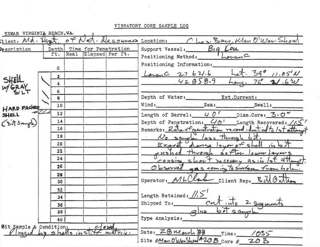
Vibracore #20 contained very dense shell but was impeded from penetrating
the bottom further due to either the density of shell or an obstruction
and (4) The digitization of the core data resulted in an error of
approximately -1.8% or a total of 1,700,201 bushels (102,012 cubic yards)
under an area of 39,325 square yards.
Sixfoot Knoll
There were five sUbbottom seismic reconnaissance profiles performed
in the vicinity of Sixfoot Knoll. Only sections of the first four were
within the designated area of the study ( Figure 3) . The seismic records
revealed the possibility of shell being present at various depths below
the water-sediment interface. A section of the seismic record along track
line 1, typical of the Sixfoot Knoll area, indicates suspected shell at
the water-sediment interface (oyster bar, possibly living) and under three
feet of overburden (Figure 8). The inference of shell in this area is
drawn from the interpretation of similar seismic records obtained in the
Man 0 'War Shoal area with vibracores in proximity to the track lines.
Interpretation of the seismic records suggests that shell may be present
throughout the deSignated Sixfoot Knoll area. Vertical extent of the
shell resource could not be determined from the seismic records.
No calculations estimating the density and quantity of shell could be
computed for the Sixfoot Knoll area. However, suspected shell was present
throughout the entire area or approximately 2,577,300 square yards.
27

FIGURE 8. SECTION FROM SEISMIC RECORD ALONG TRACK LINE 1 AT SIXFOOT KNOLL (BETWEEN LORAN FIX MARKS 1-1 AND 1-2) .
28

.w W I.L.
GRAY SILTY CLAY OVERBURDEN
WEST SUSPECTED SHELL SUSPECTED OYSTER BAR ( living)
OUTGOING SIGNAL WATER SURFACE WATER SEDIMENT INTERFACE
o
30
6o rE_1IMN
90 ..-
I ..-
NAVIGATION FIX MARK
o 100 200 300 YAROS
MULTIPLE
N I ..-
EAST
10/6/87

Area 8
No seismic records were available from this area. Therefore, no
estimation of areal extent of suspected shell could be made.
The one core taken in this area indicated a shell bearing section
with a four foot gray mud overburden (Appendix 8, Table 3) . However, the
analysis of this core indicated an amount of shell beginning at the
water-sediment interface (Appendix 8, Table 4) . The description of the
core is interpreted as being cursory. The low amount of shell present in
the 14-19 foot core section possibly indicates a time when the area was
uncolonized.
Digitization of Area 8 indicates there is 2,404,875 square yards of
bottom (Appendix C, Table 9) . At core location #1 there are 48 bushels of
shell per square yard of bottom to the bottom of the shell bearing layer.
If this core is representative of the amount of shell within the area then
a resource similar to that present at Man Q'War Shoal could be expected.
However, without more intensive coring the occurrence and density of shell
cannot be estimated.
CONCLUSIONS
8ased on the available data estimations show approximately 7.56x10⁶
bushels of shell in the Sevenfoot Knoll area and 94.5x10⁶ bushels of shell
in the Man Q'War Shoal area. Sixfoot Knoll contains shell but the density
could not be determined from the seismic records. Area 8 contained shell
as determined from analysis of one core taken in the area. The one core
taken in Area 8, however, could not be expanded to encompass the entire
area. Therefore, only the local density was determined at 48 bushels of
30

Shell per square yard of subbottom disturbed to the bottom of the shell
bearing layer. The actual densi ty of shell in any particular area may
only be known after dredging has commenced.
31

REFERENCES
Halka, Jeffrey P., 1987, LORAN-C Calibration in Chesapeake Bay: Maryland
Geological Survey, Report of Investigations No. 47, 34 pp.
Hobbs, Carl H. III, 1987, Occurrence and Distribution of Shell in the
vicinity of Parker's Rock, Pocomoke Sound, unpublished report to the
Virginia Marine Resources Commission, 17 p.
Langenfelder, C.J., 1988, Telephone conversations on dredging operations
in Chesapeake Bay.
32

APPENDIX A
SEISMIC SUB BOTTOM DATA
33

TABLE 1. CORRECTED TRACK LINE FIX MARKS FOR SEISMIC SUBBOTTOM PROFILES IN VICINITY OF MAN O'WAR SHOAL
UNCORRECTED CORRECTED BOAT LORAN LATITUDE LONGITUDE LATITUDE LONGITUDE
TD-X TD-Y DEG MINUTES DEG MINUTES DEG MINUTES DEG MINUTES
SOL 1 W-+E 27630.00 42862.00 39 11.3184 76 22.7888 39 11.3532 76 23.1102
27627.00 42862.00 39 11.2830 76 22.1915 39 11.319 1 76 22.5124 27624.00 42862.00 39 1 1 .2482 76 21.5955 39 11 .2850 76 21.9159 27621 .00 42862.00 39 1 1.2134 76 20.9999 39 1 1 .2511 76 21.3199 27618.00 42862�00 39 11.1788 76 20.4053 39 11.2 173 76 20.7253
EOL 1 27615.00 42862.00 39 1 1 • 1 440 76 19.8 116 39 11.1841 76 20.13 11 SOL 2
E-+W 276 15.00 42860.00 39 10.9856 76 19.9269 39 11 .0252 76 20.2464 276 18.00 42860.00 39 1 1.0204 76 20.5206 39 1 1.0591 76 20.8406 27621.00 42860.00 39 11.0552 76 21.1 157 39 11.0930 76 21.4362 27624.00 42860.00 39 11.0905 76 21.7113 39 11.1269 76 22.0322 27627.00 42860.00 39 11 � 1 255 76 22.3077 39 11.1612 76 22.6291
EOL 2 27630.00 42860.00 39 11.1610 76 22.9051 39 11.1953 76 23.2269 SOL 3 W-+E 27630.00 42858.00 39 1 1.0030 76 23.0219 39 11.0374 76 23.3437
27626.60 42858.00 39 10.9625 76 22.3448 39 10.9985 76 22.6657 27624.00 42858.00 39 10.9323 76 21.8271 39 10.9689 76 22.1484 2762 1.00 42858.00 39 10.8973 76 2 1.23 1 1 39 10.9346 76 21.5520 27618.00 42858.00 39 10.8623 76 20.6360 39 10.9010 76 20.9564
EOL 3 276 15.00 42858.00 39 10.8277 76 20.0418 39 10.8671 76 20.3618 SOL 4 E-+W 27615.00 42856.00 39 10.6698 76 20.1572 39 10.7089 76 20.4776
27618.00 42856.00 39 10.7043 76 20.7518 39 10.7428 76 21.0722 27621.00 42856.00 39 10.7394 76 21 .3469 39 10.7764 76 21 .6682 27624.00 42856.00 39 10.7744 76 2 1.9434 39 10.8108 76 22.2647 27627.00 42856.00 39 10.8099 76 22.5403 39 10�8451 76 22.8621
EOL 4 27630.00 42856.00 39 10.845 1 76 23.1386 39 10.8799 76 23.4604 SOL 5 W-+E 27630.00 42854.00 39 10.6874 76 23.2553 39 10.7220 76 23.5771
27627.00 42854.00 39 10.65 19 76 22.6570 39 10.6872 76 22.9784 27624�00 42854.00 39 10.6165 76 22�0592 39 10.6531 76 22.3810 27621.00 42854.00 39 10.5812 76 2 1.4627 39 10.6185 76 21.7841 27618�00 42854.00 39 10.5462 76 20.8667 39 10�5842 76 21.1880
EOL 5 27615.00 42854.00 39 10.5114 76 20.272 1 39 10.5505 76 20.5930
Key
SOL - Start of line
EOL - End of line
W - West
E - East
34

TABLE 2. CORRECTED TRACK LINE FIX MARKS FOR SEISMIC SUBBOTTOM PROFILES IN
VICINITY OF SIXFOOT KNOLL.
UNCORRECTED CORRECTED
BOAT LORAN LATITUDE LONGITUDE LATITUDE LONGITUDE TD-X TD-Y DEG MINUTES DEG MINUTES DEG MINUTES DEG MINUTES
SOL 1 W-+E 27619.00 42830.00 39 8.6627 76 22.4510 39 8.6993 76 22.7760
276 16.00 42830.00 39 8.6266 76 2 1.8523 39 8.664 1 76 22.1768 276 13.00 42830.00 39 8.5911 76 21 .2549 39 8.6295 76 21.5790
EOL 1 276 10.00 42830.00 39 8.5554 76 20.6584 39 8.5947 76 20.9821 SOL 2 E-+W 276 10.00 42827.00 39 8.3 183 76 20.8301 39 8.3572 76 21.1546
27613.00 42827.00 39 8.3544 76 2 1.4270 39 8.3924 76 21.7520 276 16.00 42827.00 39 8.3901 76 22.0253 39 8;4274 76 22.3503
EOL 2 27618.00 42827.00 39 8.4142 76 22.4245 39 8.4503 76 22.7499 SOL 3 W-+E 27618.00 42825.00 39 8.2565 76 22.5398 39 8.2926 76 22.8653
27615.00 42825.00 39 8.220 1 76 2 1.94 11 39 8.2576 76 22.2661 27612.00 42825.00 39 8. 1841 76 2 1.3432 39 8.2226 76 21.6678
EOL 3 27610.00 42825.00 39 8. 1606 76 20.9445 39 8.1992 76 2 1�2691 SOL 4 E-+W 276 10.00 42823.00 39 8.0022 76 21 r0590 39 8.0411 76 21.3840
27612.00 42823.00 39 8.0262 76 2 1.4572 39 8.0649 76 2 1.7827 276 15.00 42823;00 39 8;0624 76 22.0560 39 8.0999 76 22.38 14
EOL 4 276 17.00 42823.00 39 8.0864 76 22.4551 39 8. 1232 76 22.7815
SOL 5 W-+E 276 17.00 42820.00 39 7.8497 76 22.6282 39 7.8864 76 22.9546
276 15.00 42820.00 39 7.8255 76 22.2285 39 7.8630 76 22.5545
EOL 5 276 12;00 42820.00 39 7;7895 76 2 1;6293 39 7.8275 76 21.9557
Key
SOL - Start of line
EOL - End of line
W - West
E - East
35

APPENDIX B
VIBRACORE DATA
36

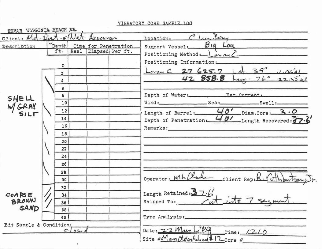
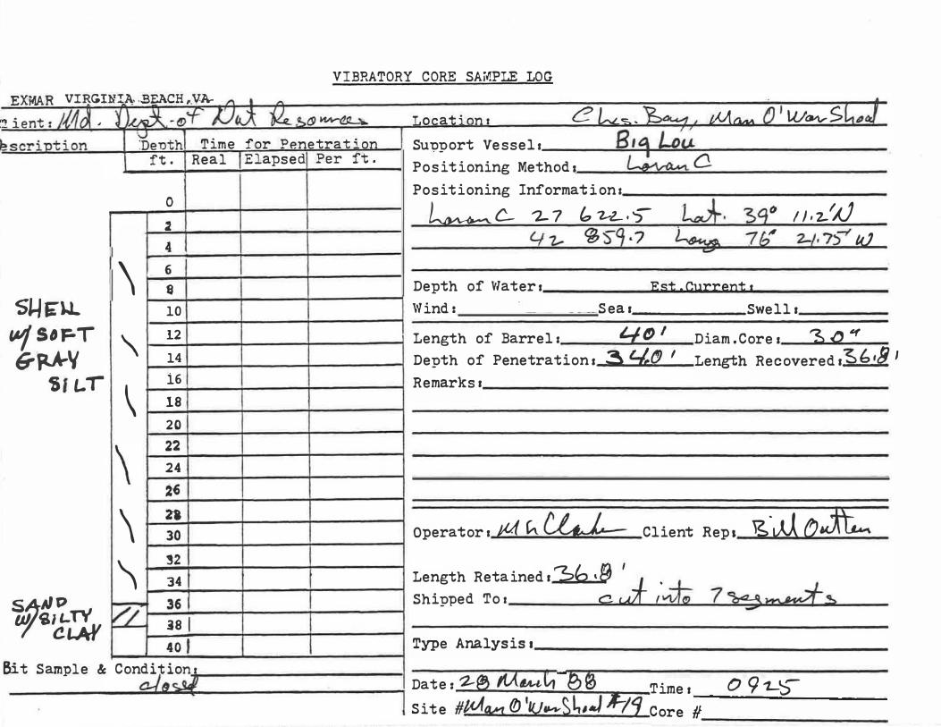
TABLE 3. CORE LOGS RECORDED BY THE EXMAR COMPANY OF NORFOLK, VIRGINIA.
37

VIBRATORY CORE SAi/.PLE LOG � X "'. ;"R VIRGINIA . ..BEACH . VA-- _ . - - - .
�
D 1 :. en"".: : /vLk f)�, .... 1 - aI--f ,U � - � � ..,l.tvU--�
Ie � :: � : n -: ; 0 n
SoF-T �V
SII-T
�eL.L u./"AAV
O�T)"th
./ � " \
J'+ - .. .
O I 2 4 6 I 8 10 12
�ime for Penetrat:on Real ';:"ansed' PeT' -f'-�- . I - - - "'" •
I I
I I I I I
Locationr ('!fi fl./J_A 41�/Vk �J.A / I � u Su"Oport Vessell � ic-tA..-Positioning l"ethods L� C!-Positioning Informationr
i..a:r .31 0 {'}1.� , L� J�7 (7 ;;2i I
Depth of V/ater I /0' Est.Currents Winds Sear Swelll ,
I Length of Barrel t �O' Diam.Corer �.O ." &/I..T \ 14 I Depth of Penetrations 3tL-' Length Recovered 1"2k·� " /2 � V1--l t,q.f,�
7! i6/ I I lsI I ,
CoA�E 'l 20 I wu. Tfii / 221 1 Stil1tp C'oA II-�Ii � 24 I
6A./JWN 26 I I .5MJ> " .nl 30 �'2 I 34 36 38 I I I 40 I
Remarkss R�� To )...DI �_ ��t"J -J� �z-' ,� ('(')�� ':!::.� •
)Jo } Cl '>� 1;P --,c So _� L -f-L.-vD �..L'11L- c::;t;;Lr dV � L--z O'-t- 'Y\.L C' 0 LI-� � � ";. a b &t L (, J � jv loco> r. o-r ��.L of I;� Us,", f--t I-I:;;'X*) st'--L±- ) a l-f.o!'1r
Operator I
/ U
jItI) L OlL Client Reps ��M Length Retainedl�,L-.�cd�, Shipped TOI 711ft.. Type Analysis.
/
o �-fu:,.,.
Bit Sarr.ple & Qrji tiofBc l tJ I (' , I' (' eo/ <2 /" � Date: 14 Mth1'�ge Timer //<1-0
\ 1\ _. I '} 1 . c � IS�te # �V�IJ?Mn,-�.,(-. /) . )

c
D
VIBRATORY CORE SAit1PLE LOG
1:' y.;.'}. R VIRGINIA . .BEACH. VA - - - . -l ; en": : JY1/�' )),..3.--. �ft..2.� . �c..,'l)WY�-L � e sc::: D-:�on i \1>enth
... � - .. -
0 SoFT
/j :! GAAV
SI L. 'T / 4 6 I
\ 13 S�E\...'- 10 tA.J / (,.AA'I
\ 12
S.'L-T 14 16/
\ lSI
\ 20 I 22 24
CoAILSE: � 26 �D 21
'/ 30
�'2 34 I 36 I �8 I 40 I
Time for Pene��ation Real
I i I 1 I
I
... , d' p J"+ .r. ... apse i - er _ v .
I I
I ! I
t I
Bi -:: Sarr.p2.e & condi .. t)01: 1;1 (' a (' 4!........ c- oo:..c
Locations CN/J.-ddt///./-t- � I Su�port Vessell 'Bur J.�(I
V)tI�e. Positioning Method. Positioning Information:
u,r 1-&7
a.�O.�t." � 14: 4 .:L J.j, 2
/ )
Depth of V/ater I e.� Winds Seal
�st.Cur�entl
Swelll
I Length of Barrell '1:.0 I Diam.Corel �.O " Depth of Penetration I 3S:' Length Recovered r 3/-0 Remarks I
I
I
Operator I Ai< � Client Rep. ��� Ow-ri; .... I
Length Retained. 15/-0 Shipped To I jntf �4..f!.. kwey Type Analysisl
Date: Time I If i'VJ�h �a l � tJ t!) i ; 1 5i te # �£.(� roPe-\- kw#tl1h- Core 1/ .jeff) DC;. �I 26 0 ;21,�
I

VIBRATORY CORE SAit1PLE LOG
�Xi'·.A � VI RGINIA ..BEACH, VA-.-
:1 j ent : J-'/o\ . i 1� . , <f }J c,;X. j2, c; .. '"vti-� )o<;c:� n�ion �
Deuth Time for Penetration ft. Real Elapsed Per ft.
0 SO,:., V' 2 �" II 4 &''-T 6
\ s
5*1 eLL 10 I
\ tJ/C,AAY 12
�'-T 14 I \ 16 I
lSi
\ 20
\ 22 24
� 26
coARS" 2"8 )0
SA�J) I �'2
I; 34 36 .is I 40 t
Sit Sample & Conditionr
Locationl t�tJ-��k ;&./01' Su�port Vessel. � � (! Positioning Methods C11cVl-a'?'V e Positioning Informations
Lat ,Jq CJ (}1, & /
4?tJ 24�() �1o �
Depth of Vlater. )0 ( Est . Current s Wind. Seal Swell.
I Length of Barrels Diam.Coret �.O H 1..(2' Depth of Penetrations �(2' Length Recoveredr � · S 51 Remarksr
Operator I EllcCf42.,.- Client Rep, "6 v�, o�H�&'\. b -I Length Retainedl � ,�
Shipped To I }11.IL M� �� Type Analysis I
i Date: / if If'krrh.'$3 , Timer /5'55 , 1 Site II � �tkl.{"q .#-3 Core # 31 0 (/t. (.; I 710 v�. 0 f

a �
VIBRATORY CORE SAiJIPLE LOG �Xil.AR VIRGINIA: .BEACH, VA--i en� f ;v1� ,})ak· �O��4� SC:-�D�'on
�'F-r (5;AAV SI L..,-
c:.��L.L. t1fi.AAV
511-\,
SR.O""�AT PE CoAJl.,Se
8RD""tJ SMD
DeT)th
If/ \
\ \
\ \
///J �" � -
f"� - .. .
0 2 4 6 S. 10 12 141 16 I lsi 20 22 24 2� 21 30 3'2 34 I 36 �8 I 40 J
Time for Penetration Real Elapseci Per ft.
I
I I
I I
I I I I I I I
I
Locationl !!�/J"/LA;lv?J'!.U �1 SU1)1)ort Vessel. ' � Lc-i .... Po�itioning lw1ethod. 'Ltn..4� G Positioning Information,
ktt;r 3el � 01 . ss-I � 7� t) 2 tI. f) / ,-Depth of �/ater I // / Est.Current, Wind: Seal Swell,
! Length of Barrel r �O/ "3 1/ Diam. Co:-e I • 0 Depth of Penetration I �Z' !.ength Recove:-ed ,'3/. 7 Remarks I
Operator! I�L��� I
Client Rep I � j� () ltfL Length Retained. 3/·7 Shipped Tor /n�. �� 41vu<evZ 7 . Type Analysis.
Bi --:: Sarr:'D�e & Condi ti0I;:f . c�tc r:i::: c l�*, Date: t.l!. jl1�� 1{g� " . Time, /��c;-�- - - !Site # Sv�&etk�.Jlty . Core # 31°01.55' 76°;2J../,O,J
VIBRATORY CORE SAMPLE LOG EXMAR VIRGIN A: .BEACH , YA- , "
� J\. o-..fN J\ � � D Ily-Ctl.� 'Cl ient t .M o\} \ \J
Desc!"intion Denth Time for Penetration ft. Real Elapsed Per ft.
0
�MY � 2 SH .. I / 4
6
\ Q 10
�\-tkh'" \ 12
WIG-PAV 14
\ 16 SILT 18 20
\ 22
\ 24 26
CoAIlSE." 'l 2"8 S�AJ 30
SA.al> / 32 ,. 34
36 �8 I I 40 ,
Bit Sample & cond ttiol ' Cl- OM
Locationl C'lcs. ��vf SUT;>port Vessels f.3;r4/ � Positioning Methods ?I Positioning Information I
L <5'V'� C 7-:-7 (P�O,l y'1- �59,3>
L��c. L.�. L'k.,j .
�gD /'= �
Depth of \'Iater1 Est.Currentt
r )),l.-,v -:2.S .3,cuj
Wind: Seas Swells
Length of Barrell Lf tJ I Diam.Corel �.O II
Depth of Penetration. '31-' Length Recovered r 3/·� Remarks.
Operators t�(�� Client Repi 'tJ( ode
Length Retained s �/, S ' � Shipped Tor �1¢>3'f
, Type Analysisr
Timer Date: 7-1 4�h'cn CJ9.IO� i l Si te # JV1a11 &'tJa-vS1� I Core # ________ __________ __
I

VIBRATORY CORE SAMPLE LOG EXMAR VIRG
tel ient I MJ.� , Descri 'Otion
��AV .sILT
�i.LLS w/'-VAY
�'LT
�=., �Al)t>
ti� .BEACH I �A-LW . o'f )j aA . �.-&�)I'l Vi1 It. �
Denth Time for Penetration ft. Real Elapsed Per ft.
0
/; � 4 6
\ e 10
\ 12 14
\ i6 18
\ 20 22
\ 24 2�
� 2. 30 I �2 34 36 �81 40 I
Bit Sample & conditi� (lIG
Locationl (' k_co oD<41 SU'ODort Vessell � L� Po�itioning Methods Positioning Information:
h�C "1-7 b'2-@, b l/1- SS-£!.'2-
Depth of Viater. Wind: Seal
LcYv�C
�:!2f:. 'S � )1·1 A1 L"vg , "1b � '"J-3·/W
Est.Currentl Swell.
Length of Barrell 4DI Diam.Core. '3. (J'" Depth of Penetration. 3�' Length RecoveredJ�d.� Remarks .
Operator I 1-<4 t � Client Rep, "&�y�� Length Retained. 30· 'L-
yY/t(. �'cd �u� Shipped TOI
Type Analysis.
Date: U If,,(� �; �� Timet j olD • . j Site # ffMt C 'r{lv/�L,�Ff :2. Core # ---------------------
I

EXMA R VI RGI1HaA� .Il �CH , VA;. VIBRATORY CORE SAMPLE LOG
.C' ient I /VJj. ikn . �� LJ �. �,!..dl Vc)'"'.!. � � Location I C' �� \ � Descr; . . otion �euth Time for Penetration Su�port vessela __ ...:I4i4r.::: ·;F-"':"'�""':'- "";;;"'/ _________ _ _ ft. Real Elapsedl Per ft. P ' t' . M th d tr L /'I OSlo l.onl.ng e 0 a __ ......::;;;:.;fN'���_'-______ __ _ _
o Positioning Informationz ____ ____ __ __ _
2 L,)o q.,.,c. . '1-7 , G '1-� . � � ai. � 9 (7 / I • �IJ / 4
L/'1-. 1259· b �();vr3' 7 1/:1 ?-�. )u.J S�tk� �6 �--4_ __ -+ __ --�----------------------------------UJ/GflA'I / 8
Depth of \'latera Est.Current.
ca., L T 10 Wind I Sea 1 Swell. / 12 Length of Barrel. 'to � Diam .Core I '3 - 0 1/
14 Depth of Penetrationr :?b I Length Recovered .3ff'1 i6 Remarks.
/ 18 ----------------------------
20 22
/ 24 2�
��;A�QI'C�\' : Operator. pt1k� Client Rep. 'g,A.( oL ��� � n I SaLT IZ 34 Length Retaine�'( , 9
� (!()1't� /" 36 Shipped To.--'-m-.:.'d�....;...·.:.....;�::!i:;;l'��tJu:.� ·�d�..::::-..=...::::::::..:::::::�l------:sAiOI> � 8 I I /I 40 J Type Analysis • __________ ____________ _
Bit Samnle & Condition' -----�--*T'"""'T-. =-:------------------C I (pwl , Date: 7-1 rt1(W¥C1 '�� Time. II (J S-1 Site #t1M1 O'IUt1V344J -;l3 Core # ______ _
I

VIBRATORY CORE SAMPLE LOG EXMAR VIRGIb
Client .-.A? ). - .
Desc!"i'Dtion
SH� -wj�A"
�'LT
t;,MV �, LT'/
CLAY
�A: �EACH I VA- • -
) -�r�" JJiA. f,& �� L(V�L> IU Deuth Time for Penetration ft. Real Elapsed Per ft.
0 �
/ 4
I 6 e 10
/ 12
I 14 16
I 18 20 22
/ 24 / 2-6
Z8
� 30 32 '\
I!o",� t\ fJ> 17/ 34 36 .i8 I 40 J
Bit Sample & Conditions t! I t!!J '"H J
Locationl C��. :g� SU'D'Dort Vessell � Ltn<..! Positioning Methodl ��a..".. � Positioning Information:
l��{} -z-1 .&?-9.L L�, ��f' 1t.,3N l/1- tfbO,t.) L.�I .7/2° "'"J-7... '7 B u.J
Depth of Water. Est.Currentl Wind: Sear Swell.
Length of Barrell t:J. 0 ' �.(!)., Diam.Corer Depth of Penetration. �q i Length Recovered. �S.! !I' Remarksr
Operatorr ;11L,(}l� Client Rep. \>"JA�£ Length Retained. 3 S". 8' 221ri�{�7 Shipped TOI
Type Analysis.
Da te : "2-1 dif �Ct 'B� Timer /1 �O !Site #MMf�/��4;JtljL/ Core # _______ _

EXMAR VIRGINI,!.: .BPCH I "A-VIBRATORY CORE SAMPLE LOG
Client s A1J,.. tlJc· o-FPI:J::,,_ ��o\.{y-�� Locations C k�. 1Zv� ... Description I UOenth Time for Penetration Su�port vessels __ �tt&��'g�_i-�� ____ / __________________ ___ 1 ft. Real IElapsed l Per ft. P ' t' . M th d I L ......, � ____ � ____ � __ ___ +-I ______ � os� �on�ng e 0 s ____ �������� ________________ __
Positioning Informationl ____ __ __________ ________ -----
l� c. '2-7, b27.'1 L.....�.�q" J ) ,2'/J '-1'2-'_ e 15"1. � ��V1Q' '7 (/' -:l-Z , � S'CU
-;,.J
Depth of Water. Est. Currents �--�----+-------�------�I Wind: Seas Swellt ________ __
1--4---+-----+-----11 Length of Barrels 4()1 Diam.Coret '!t.DN � � I I Depth of Penetrations :3 b I Length Recovered. �Z..7' - i I Remarks 1 _________________________________ ____ ___
1-1 ......::.-,:.-+-1----
-+----+-----11 Operators tNll�u-- Client Rep. D"t{ OL
:- : I Length Retained I :; � _'
--4-----;.-----l1 Shipped Tot n1d. �g/� �
I . . T �
. Date I '2.-/ AI( �4 .• A,"�� Time I I 3 IS-_______ --IL"..J.,..Q9'�o ::!! ..... 1-_ ___ _ 11 Site #��/LU���:Jit S- Core #

VIBRATORY CORE SAMPLE LOG EXMAR VIRGINIA .BEACH. VA-- - "
Cl ient f �J.. .. f)� ,,,o::p m t �9- OLty�!. Desc!'i 'Otion '6euth Time for Penetration
ft. Real Elapsed Per ft.
O 2
/ 4 6
/ �
51-1 £ L.\.. 10 12 LfGRAV 14 C;aLT
/ i6 18 20
/ 22 24 2�
/ n 30
WH \Tfl\"'t> 7;' �'2
(!"A-�E AJ � 34 SAoul 36 SAN.,.
�8 I 40 I
Bi t Sample & CO�d�t;::t
Locations C' ��.�� Su�port Vessel. i3d:1 Lh<--Positioning Method. 1-�� C-Positioning Information:
I bc�C 7-7 ',1.9 l-.'� 3qe 'I·�N '-IZ 95f .. � 4....,. 76 7=-
1,'1CI Depth of "later. Est.Currents Wind. Sea. Swell.
Length of Barrel: 4{)1 Diam.Core. "3.t) ., Depth of Penetration. 36' Length Recovered. '3S'"., Remarks I
Operator. tA1lvdlLL. Client Rep, ��'{,{ O"'�
-- D I Length Retained I '3, � •
Shipped To. m,i ffitCoF'-�
Type Analysis.
Date: 2::1 M�C; '8� Time. /�Jc.;-1 Site #/�a.-vr D'tUav.->�mJt 6 Core # _______ _
I

VIBRATORY CORE SAMPLE LOG EXMAR VIRGINIA .BEACH. VA
C' ient I h1 �r '1 J .... J-. »�, tl1.-$t9l.i y"U�
Descri ution \d Denth Time for Penetration ft. Real
"B�� 0
�/ . , :"- �
\ 4 6 8 :!t��l..'- \ 10 WlfrP-AY 12 �ILT
\ 14 16 18
\ 20 22
\ 24 2�
\ 21 30
�olflUS' 1/_ �2 &lUuN 34 &4A11> 36
�81 40 ,
Eit Samnle & Condition, -c lr;.;;}
Elapsed Per ft.
Locations L L..a�.�� SuuDort Vessell � Ltnl, positioning Methods LeY�t2.. Positioning Informations
L�c. "'-7 ';8. .. l b�' �g. /1.- -Z!,() 951·, Lt!lkcl . ¥2.. 0 7'- Y. .. 8W
Depth of \'/ater. Est.Currentl \'lind, Seal Swelll
Length of Barrels 71.0' Diam.Cores � ./J .�
Depth of Penetration. �1 ' Length Recovered ."3B .. S" Remarks.
Operatorl 141 "'-� Client Rep. 1G J{ �jh.-,
Length Retained. ��.�I Shipped To. w1l.- �7iUtJ? � Type Analysisl
Date: 'Z-L���r�� I Times I" . "S fJ tJ 1 Site #�4II;t �/uJA--�I;J·. 7 Core # ___ ____ _
I

VIBRATORY CORE SAiJIPLE LOG �A"'J\ rt y .L..fi ......... Aol.;,..p:, ..-yr-.-.-..... , ........ -- •
C' ient t 7Chf ��. 1 cf-i..JiA . ��"&.-i�> . Desc!,i ution 'deT.>th Time for Penet�ation
ft. Real Elapsed\Per ft.
0 2
/ 4 I 6 I
�HetJ.. Q I ,.Jf r;JtAV f lO I
12 SILT 14
I i6 I I 18 I 20
( 22 24
/ 2ii � 30 I �2 I I I
eoAN£. -�
34 t SRoal#ll 361 I BAND �8 I I I 40 I
Location I Ck� �� Su�port Vessels BII! L(HA. Positioning Methods L-�c-Positioning Information:
Lrrr:5V\C- 'Z-7 , 1-7·7 L-.v+ 3'i4 u .7...$'P t.f 7- 8' f) a() b5;' 7(,. � '2..1--" 7'W
Depth of \'later. Est.Currents Wind: Sea.
, Length of Barrel. L.( �' Depth of Penetration. � - ,
Remarks I
Swells
Diam.Corel '3 .061 S-.8/ Length Recovereds!)�.f
Operators M'-ct.· L Client Reps R. (,,,,11 )YYl9fA1:S"r Length Retained. '"3 s: 8 '
J Shipped To I C I !:::l I �
Type Analysis.
--:J. ����
Bit Sample & Conditiont. , 0-- I Q'?d-:-tJ I Date: kk JV1ibJ11'ml 1 Site # J-v\�dwrol/J � a
� ime I eJ C1 ")" Core # --------------------

VIBRATORY CORE SAiv'lPLE LOG ErAAR VIRGINIA. ..BEACH. VA--- . ,..
C' ien"t t fo1 J � -�. o-P iJJ\, � � (J�Y'� De sc'!' i u"t ion � Deoth Time for Pene�ration
ft. Real ElapsedlPer ft.
0 I �
� 4 I 6 � I 10 i ;t--.atLL 12 tfJ/ G-P.AV ( 14
SI LT i61 I I
/ lsi 20 I
( 22 24 2� I 21 PAR.kSo.L.. 30 .....
coA� � 32 I 34 I t "8�p
"
36 �81 I I 40 J
Bi t Sample & Condi t;r�J
Location: �k�,� SU"9port Vessel' 8,� Lou.. Positioning Methods 10 �C-Positioning Information:
� c LeA· I/f I 'AJ 2-7 47.L .. , 34f41 1.f7- BS1· D �. 7 /:,0 '2:"2. ·PUJ U,)
Depth of Vlater s Est�Currentl I Wind: Seal Swells
I Length of Barrell =to ' Diam.Corel � .t!J " Depth of Penetration I 3�1 1... Length Recovered s33 • � Remarks I
Operator I p1 L� Client Reps R ,(0�bw-��� , L0\1.
Length Retained. 53· L. ...:+ Shipped To r C' .' ;�t Type Analysis.
Date: �1..--A� �'�· If\' _!.mel
G s�,� -::. ='
t..S--Z-O 1 Site �CJ�L..;.;t!1 Core # _____ _ _

VIBRATORY CORE SAi/.PLE LOG
En-.AR VIRGIli� �EACH, Y-A--C' ient r JU � 1 ·O,,�.;f- 1.Jc9t. � � "V\.,...tL� Desc�i 'D"tion l'-l Deuth Time for Penetrat�on
ft. Real
0 �
\ 4 I 6
SJ.l��L e 10 J,V' / GrAA 'f \ 12 S/l-T 14
� i6 1 la 2Q
\ 22 24 2�
� �2'8 30
�2 I 34 36 I aDAIlS� VO jal 6P.�'J> 40 J
Bi� Sam'Ole & Conditionr -C- '6;::/
ElapsedlPer ft.
I
I I
I I I
I I I
Locationr C�� � Su�port Vessel r B, � Lo fA. Positioning Method s L�c Positioning Information:
L�C. 2::.2 �2.�2 L#t: '3 2- ll·�/AJ 1/7- eS",� 7 Leffj ' 74· -z.� .9'1(/
Depth of Vlater t Est.Currentr \'lind: Sea l Swelll
':f. f)f 3-0 Length of Barrels Diam.Cores Depth of Penetration. 'i. () I Length Recovered .36.-8 I Remarks.
Operator r }'Uk. Ol6.L-client Rep. {;.. .cJ��): ;:::JYI, Length Retained.S fa ,�I Shipped To r a. wf I � ) 0) - . Type Analysis.
7 9!fd 1-1-�
Da te: 2- '2- M CJ;Vt t I @)� Timer LQ6S-• 1 S ite #� ()IW�$t..tJ4rJl.-l{Jcore # ______ _

VIBRATORY CORE SAil.PLE LOG
'::'kl"ll'\n .,��,,-----: "-"1.' ----r �--
C' ient: MA. 1J tdt.. .. �..s�(,{ yt� Locations C �� · �..., Desc�';'D�ion
' De'Oth Time for Penetration Su,?port vessel ' _ _ .Ji:B�,�t:::I--.:::::J!;.::;D..:::U.� _ __ _ _ __ _ _ _
ft. Real Elansed l Per ft. P 't'
, M th d � .L----4---!-.....;.;....--+-------� os� �on�ng e 0 l _.....a:::;;���'--...;;;;;;.. __ __________ _
o I I Positioning Information: _____ ________ _ _ _
;Z Lt"�a-c 27· ,1=4.'3> Lt· 31" ".�' AJ
\ 4 '1-7.' QM.2. L�.. 7 '" 2.."2-·3$',,",
S \...1& \.1- : Depth of V/ater I Est. Current I
wI t;.AA'( 10 , Wind: Sea. Swell 1 ____ _
� I '",- \ 12 , Length of Barrel. Lf a I Diant . Core . �. Q It 14 Depth of Penetration. -Sq I Length Recovered,-S/,D \ 16 I I Remarks: ___ �-------------�--------lsi I l? �d�d- -; � �t- �. (J "" 4.-vl./ J v...D-- ) (p � .... \ 20 I fJI f �t9� �_�.!:l 10 .... / -hll'l v ... .r.;J 22 _ � ��j;-� , I �
24 1:) -----------------------------------
CDAtuae / �2_-6 ..I..-...-...;-------+-----i ===========================::;::===:::;:======
I
1!>�A1 / / 2"8 S A,.I,P Y 30 I Operator r 11 h � Client Rep. � . Ctv"i\ � � ��.
�2 I I 34 I I Length Retained. 3t· � � ,== L 36 Shipped To I C � 1 � � su l.oVt.�G is I I I 401 Type Analysis . ____ _ __________ ___ ___ __
Bit S�ple & Conditions � _____ �_�.I ��----------------� -0 )..yl i Date: 7:-2-JI!1<1'ttLt es Timer 11-'2.-� 1 Site # M PNl ot W...,c£---;;;r=t../! Core # _ _____ _ _
VIBRATORY CORE SAMPLE LOG �.h.I"lJ"\.n. . .. . �Y'.��: ..... -._ ... , ..... _-- •
C' ient I .xAo\. i� �Q)'f )Jilt..- 4);�OI.l�" Desc!"'i 'O�ion
UDeuth Time for Penetrat�on
ft. Real Elapsedl Per ft.
0 � I
\ 4 6 I I
SHE: LL e I 10 I w/ c,.p.A� \ 12 $'Lr 14
\ 161 I lsi I
\ 20 22 24
\ 2-6 28 30
� 32 I
CoAPSE 34 I t &IlDWN 'j 36 I j SANP i81 I I 40 J I
:Bit Sample & Conditions l c/ Q-b
Locations [7 k-:.. ,�-Sut)'Oort Vessell �I� L'o� Positioning Methods l ... t9-'V-a..., C. Positioning Information:
L�'r-fWt � 2-7 '-z.,s=o 7 L ak- -SqC' )1,Ob� 4l'2.. 9sS-S La±:). 7 b f!? 2-"L.� '5' t<J
Depth of Waterl Est.Currents
Wind: Seal Swells
I Length of Barrel t '-I ()' Diam.Cores 3,-0 Depth of Penetration. 4(2' 37-" Length Recovered.il:z-' Remarks.
Operator. )AI\ �Cf.L.- Client Rep.R. ('�t�� 0}'". Length Retained.3 7 '� . ...;;t-;;-
.J Shipped To. c.. z " 7 �� , Type Analysis I
, Date: -Z--Z r1/lQ1ct C I 00 17-1 () Time I
1 Site #MQIAI1b\.dll+-�L;rJI4ore # ______ _

VIBRATORY CORE SAiV!PLE LOG
t;"XMAR VIRGINIA .BEACH. VA-_ ...... - - .. - , A C' ient t �1t"\. � ).LA 1; - M't AJil\.. lk. � C> 14 V' M-So Desc!'i '0-: ion �e1)th Time for Penetration
ft. Real ElapsedlPer ft.
o I I � I
) 4 I 6 I I �� w (;1l-AY 9 I
/ 10 SI L-r 12 14 I
� i6 I ! 18 20 22 24
G-�A\' V � 2�
Ca." 23
CDAP-Se ,J � 30 I S� �2 I SAItIP f.- 34 I
36 �8 1 I I 40 I
Bit Sample & condi;irn:q
Location s Ck",�� Support Vessels �'o, 7l-ou. Positioning Methods ov-�C Positioning Information:
L�VLtacC 7-7 &2-� . '"L lJ· �1� J) .2-IJ ttl.- �:> j 'D kv;:,. 7 bel 7-'Z..·£!tU
Depth of \'later I Est.Currents
\'lind: Seas Swells
I Length of Barrels <::i.. () , Diam .Core I 3 .. 0 '"
2a� I cr l Depth of Penetration, Leng-th Recovered,32. � Remarks.
Operator I J4l- � Client Rep.� . ���k1am� :-:J", ,
Length Retained I 3 2.. ' q I Shipped To r c;J "\Afp Type Analys is t
Date: �'1-- 1V1� tl'�� Time,
(, �jJ .
i /2-<-:>-S I Site #�� b'w,-�Lt.;t1;-l� Core # ______ _

VIBRATORY CORE SAiw1PLE LOG
.!:;k/flP.t{ v .J..L\,,,.J.. ... �: ""t� ....... , •. �
C' ient : 100\· � �. L. OS!!) Vl yU� Desc'!"i "Otion De'Oth Time for Penetration
ft. Real
0 �
� 90F'- 4
tnI-A'I 6 I SlL--ti( 8 CLAY / 10 12 14
sk-lEL.�
� i6
�Gp.AV 18 .11.-. 20 I 22 � C-tl�Jt5"
� 24 BRow'" 2fi SANJ) ! pi 30 �2 I 34 I '6 i8 40
Bi't Sanrole & Condi t\on r -�. �
Elapsed l Per ft.
I
I
I I
I I
I I
I I
Locations �k��� SUl)port Vessell Bl,fJ Lou Positioning Methods L2�C Positioning Information:
L,� c 2-7 b?di..·1 �J, �:z e1 I ) j.) V 4-z.. 957·8 L�. 7b� I "l--�./ tV
Depth of '{later I Est.Current.
Wind: Seal Swelll
, Length of Barrel s 4-e>1 Diam.Core. �-D Depth of Penetration. '::L. (!) ( -I Length Recovered. 2.9"$ Remarks.
�-� I" A J'+- <:- L � '" � �"y erl ""'-4..----1-"bt!> "V'4. /.7() o.,.A .I-:ry:�� � �/v-" , !!::. o�;-Q. K c-r-� u J ��r / / /
I_H,J
Operator I In b � Client Reps i2. Ca:t:��, ;
Length Retained ,7--9 ,S- / Shipped To I (?;5t ; J Q
Type Analysis I � .
by-:;��
Da t e : --z-""2-l!1 � r g> � �4f) I Timer 1 Site #!Y.fY1 (jW.�p)··\.()HILfcore # ______ _
'J'�I

VIBRATORY CORE SAir'IPLE LOG
EXMAR VIRGI1:f!,l\ .B�CH, VA-C' ient t Iv! tA . � �. CJ -r JJ iA· fYa S>o u V't1L> '...J Descr; p-:ion Deuth Time for Penetrat �on
ft. Real Elapsedl Per ft.
0 �
\ 4 6 S�&\...\.... e
1M�'l 10 S. a...r
\ 12 14 16 I 18
\ 20 22 24
\ 2� I 2"1
\ 30 �2
PAp.k SOIL .. ZZI2 34 A�P uJ"'P 36 i8 1 I 40 I
Bit sam1e_ \;[fdition, S� """'" I 0 �l I
I
r
I I I I I
Locationr CJk�.�� Su�port Vessell 8i � Loti... Positioning Methods � C. Positioning Information:
L�4Z1 {] 2:=7 b z.lf: � k� 3q� I ) J .'2-ll
t.ih 96" ·0 L-.�. 7 bl# '),.:1- . / I I.U
De,pth of \'later I Est.Currentl Wind: Seal Swelll
I Length of Barrel I y... CJ I Diam.Core. S ·0'1 Depth of Penetrations Sl C2 ( Length Recovered,�S'7 I
Remarks.
ope·rator.;11L� Client Reps �. Cu.-ftLi��J � �'Y' , Length Retained I �s· 7 '
� �� .. Cw! ;� Shipped TO I
Type Analys is t
Date: �'l- )tIf� C' g� _�imel l..l.f � D I 1 Site #fM�O't.Uw-c;�JR1Score # ______ _

C!.ien-: t !'
VIBRATORY CORE SAj�PLE LOG
.!..location: 0 \"4� . �� . fot � (J'LU:vv SLo Desc!"iu-:ion for Penet!"ation Su,?port Vessell gla Lou.. ..... , d' p �.... 1 '
S"-le.l.L wi (;p.A'{
SILT
coA�e s.f4.,vt>
.t._anse I - er .l .. . p ... . M +h d r ______ � ____ �---____________ � _os� .. �on�ng ew 0 : __ ������L--�� ________________ ___
o I I 2
\ 4 6 I \ 8 \ 10 \
\ 12 14 I 16\ I lsi I
\ 20 I 22 241 2�
\ 2"a I . 30 I
\ 32 I I //2, 34 i I
36 i �8 i I 40 t
I
I I !
I I I I I � I I I I
Positioning Information: ________ �-------------------
k-a- C 2-7 '�3·' �J:. 310 /)./�/Iv' �2. 'sri. 8 L�w;; · 7 C/' "1-2.·0 'V .::/
Depth of Waterl !st.Cur!"entl
Wind: Seal Swelll ------
�e!1gth of Barrel: '-If) , Diam .Core I '3 -0 � !)epth of Penetrationr �7' !.ength Recoveredr�S." Remarks: __________________ ______ ____________________ __
Ope!"ato!" I 1{.1 � ,4td- Client Repr E�x, --,.--.
�ength Retained r :; � ·b I J Shipped TOi (' v./T ; t,..1; b 9-L,:� C..J
�ype Ana:ysisl ______________________ ________________________ _
Condition: Bit Sample & I F i :Ja-:e -,
-;;l �t.f _,l, \ e� �:''''e I C' 8'f '> <!, c� <>:f,- � , " I /.L/ " ; 5:'-:e ;: tiw".�",c r. :o:-e J1

VIBRATORY CORE SAiJIPLE LOG
_ .... - - .... - - " r C' ient : Jtt1 t.� -\l: -I�' r.+!J�- ()k S (!) ILArL.-L � Locations c.�, �A�.J M &vi C7)LU�v-s�"-,,J .Jesc!"iDtion
���\-\..-. wi '-R.�'i .,LT
COA-II.S&� ���J>
\�enth Time for Penetrat�on BI� lolA / Su,?port Vessels
ft. Real Elapsed Per ft. Positioning Method:
Positioning Information: �C 0 Lg}· //./�-/�1 2 I l�L- 7-7 b'2-3.� ��b
\ 4 I 4'2 SSCi·' 1--�. -7,=" .;; , '7 /4..,1 6 I e I Depth of Vlater s Est.Currents
\ 10 Wind: Seas Swells
12 ! Length of Barrel: � (2' Diam.Cores '3 -0 u 14 I Depth of Penetrationl �� I Length Recoveredl]S/·7 161 I I Remarks:
\ 18 2C I 22
\ 24 26
\ 2"8 e-1t eLL ��c>� 30 Operator I Client Reps
V',// 32 I I I 34 t I t Length Retainedl:>/·7
CJ-i� ��d; 36 1 Shipped TO I
38 I I 40 f 1 Type Analysiss
1.s � I$. f V?Hj ! Da-:e : "2-3 t{.(�V��
) S:' -:9 J!M,.o'WtANS4"411 17 m� � C) :> C _�rne: L' - � . Core !.'
I

VIBRATORY CORE SAr(PLE LOG EXMAR VIRGIN;rA. .B�CH,�A- _ " .
Client, M�,. �:i��. ,,-F IJ�. ��L(vact� Location. Q �o,.�... M�. 0) W4l\/SL,o� Descri'Qtion �E:!'Oth Time for Penetration Support vessell ___ Bw..;:,-=lqr--:L=.:,o :::::::u...=--'---------
ft. Real Elapsed Per ft. P ·t· . M th d 1 " os]. ].on].ng e 0 • __ ---::��t'\c��:::;.:;.:;...;;\..-;;;;;;.-. _______ _
Positioning Information 1 ______ .-.;... __ ___ _
� J-�tM�C 77 (,1--�''"2- �J-, -Sqb II. Oe � " l(� ifJh 0 ; tJ L�). 7./;/' il· e'l()
'\ --:� Depth of Water. Est • Current •
�"E,"", 10 Wind. Seal Swell.
"t'''�T ( i2 Length of Barrel. yat Diam.Core. :1 ,0 .. 31-,{ , S 11.: \ . 14 Depth of Penetration. �4 I Length Recovered I 31-,(
16 Remarks. ------------------------------
\ �: 22
\ � ======�.====.=
.==================::;:==:::;;===
� : Operator I tM�.l1.� Client Rep, YS.i« 0 t<..it'1, C.:, /� 32 .. , 8� / 34 Length Retained.S�1 . ' �
36 Shipped To I I d I """j; G �J� i81 40 , Type Analysis , ________ _ _________ _
Bit Sample & Conditions _______ ----"'t:"!...::....- ....... 1 & ......... S---4::i�=-- -----_ -�_-_1 Date : 2-� t«a-1l·A::t 'ge Time I /01 S-l Si te #,4(AM OIw.,..S.�;J7I / e r,,, .... o 1.' -------
VIBRATORY CORE SAMPLE LOG
EXMAR VIRGINIA, .BEACH. VA-· . ...... . ..... � ient: J/AJ. � � .., )� -(!)f lAJ... R,�� � � scription
'-d Time for Penetration Denth ft. Real Elapsed Per ft. g
0 2 4
\ 6 e
S�E"lJ.. 10
IJ/jS'F-T \ 12 G-JlA--V 14
" L.:r i6 \ 18
20
\ 22 24 2�
\ n 30
\ �2 34
r"P 36 V'/ W. �H-T'I .i8 I eJ.A¥ 40 I Sit Sample & Conditionl
Locations e k�, � � � t-<A.aM. tJ IIV�SLt.9� Su�port Vessels B,� �� Positioning Method. �Q Positioning Information:
�C- '2-7 fo�L.� Lj-. 39() II.Z-'JJ 47,,- �5q·7 � 7b 2-/.7)-,' u.J
Depth of Vlater s Est.Currents
Wind: Sea. Swell.
Length of Barrel: �f)1 Diam.Corel �.o� Depth of Penetrationl .3 '-it') I Length Recovered. �b,B Remarks.
Operator I JUt "- et...t- Client Rep, �'vU e» Jt: Length Retained I -:>b · 9 j . Shipped To I e , 0if; Type Analysis.
Date: z.e /G{£ufll e; e Times
7��:>
qd(l>&/ 091-� c 1 Site #t<Aan (!) 'IU�S�,J �/'l Core # _______ _
J

VIBRATORY CORE SAMPLE LOG EXjJ1AR VIRGINIA: ..B�CH, VA-ient:h{l�]k�·bT,.l?�. �6l.W"&� Locations �L��64<.., _ ��-{}���ItJ '" 8 To --, scrintion I Deuth Time for Penetration Support vessela ' 4 Lou
�1 _f_t_. -+ _ Re_ a_ l __ I�E _ l _ap
_
s_e_d�T _P _ e _ r _
f_ t_. __ � Positioning Methoda ____ �b����_C_ · __________ __ __ __ __
6&-t .. hL wjCrlttv
sA�1>V SILT
Positioning Information: __________ ____ __________ __ __ 0 . I I �C ?--7 C::a-',b �4. "!>9' Ild)S-'/J -
\a \ :
c.; 2.._ �5e·" 4�. 7.'/' 'Z..}' b (tU C/
"i 10 , I 12
1 1 Length of Barrel: 4-0 ' Diam .Core a � ,0 .,
""-/1 --I 1 Depth of Penetrationr 40 r Length Recoveredr It.;,/ ( V/ .. ".,j 14 10 , Remarksl��'���J�������------------------ ----)Jo \O�(j :ihV'��h cJ:oC 18 20 -! �""�¥-=:o-v: :-C:=T �y<-- J..-r-!* -22 - I G �cpb��,,� ����+- (!)� 7�' -24 26
(!J 1, �vJ __ "'-. q g. � JJ ...., ,.� -t f!) S cv-c{� � � V'\.
>-L-t-"';'v;� � �.£-.Y- • OJ
28 30
- I 1 Operators i1A["..� Client Reps �� &� 32 -34
t Length Retained r ! q. r
. ..L cJ i I Shiuned Tor C k.t ;Ji) � �\�� 36 - -
.i8 I 40 f I Type Analysis r
�t S�ple & conditionl n -a-t-
e-:-������
--���$�A�---- -
T
�i -m -
e-a--���O�f�O�------� rJfNJ I Site #M.e.a O,IV ..... £I.�jf-za ).. core # 7=oA
VIBRATORY CORE SAMPLE LOG EXIf'lAR VIRc;INIl: .BEACH, YA-
Client % )vf.J.... - �. 0 f N-y\'· J.l.Lso � Locations {' ,� .... , "f.::,� � Yv4eJA/1 OlLUa-v- <;;ho
s� ,Jr,p..4YT "7 �I \..
_ ::>r _ Per;���� t ;�n I Support Ve s se ls ___ ---:B::;..;../...;.,'1�=L;;..' cd
...;t.L� __________ _ _ .l-......;;�_4----�1 Positioning Methods � c...
Positioning Information: ___ � _______ _
. I I �C- '7-7 b'-/.1:, ha;:t. �1f1 /).b�-IIJ Lt_2-�S-�t9 ��. 7(/ �,bJuJ
- ; I
�
Operators Ml..t � Client Reps ·-v ... , ......... ,:;rp
_ . I Length Retained I /I. '5"' 1 :....j... � , Shipped To I ('tooVf" ; ""'II l-. � � I 6\9 la-it $�{�
Type Anal ys is I �----------�----���R----�I
IT ! "?3.')&-'" '0, :7 -w",,, In ,,! q r_,"""" , Y' i Date: z.e ���Tlig Times /OS>-Site tlM� tJWtaA-->heJA-20.5 Core # 2i!J �

VIBRATORY CORE SAMPLE LOG EXiJ1AR VIRGINJl'.� .BP.CH, VAr
lient: MCl\· ut:i&. � c..f ).5 ii\.. K�e'/lfr'etlS Locationt C �A.. ."g� . W�1\ �i-CJ'-fM�DllUor escription I De�th Time for Penetration Support Vessels Ba,' LOu. S "--"cvf
1 ft. Real IElapsedl Per ft . P ' t' . M th d � ....,
GI2.�'LT
$J4EWtJjG1J..AV
Sl L-T
5NJl)
os� �on�ng e 0 1 ___ ���...:o.-o =I-�=' ______ __ _
Pos i tioning Information 1 ______ ______ _ �f -� -t---+-
I---+
I-----I
I h� C 2-7,611·9 LJ. sq" II,t'lj
Y'_ 4 . . . 42-· �b6. 7 �. 7 t/ 2.0 .""3<9 II(}
6
\ a Depth of \'later I Est . Current I
\ 10 Wind: Seal Swell. ____ _
\ 12 Length of Barrel: y � I Diam .Core I :5 .. 0 4"f
�4 Depth of Penetrationl 34 ' Length Recoveredl2.9·0 16 Remarksl_� ___ -T __________ � __ � __ � ____ �_
\ 18 TQ/L A=rAGJr",r- '! lRmJ< 'i<{)g;;t
\ �� =tg,�...,�.
24 2�
f"1 =1 I 1 Client Rep, �� J� �2
: : I Operator. fA1.k� 34 I I
Length Retained. Z. 9.0 I • ..L 361 Shipped To I C uv*' I j; (;, 5?-9..t �� �81
I I 40 I I Type Anal ysis I
its�Ple&C�di)� -�-t-e-: -������ �� �,�3�---T�i- m-e -I-�/�/�3�O�---� 0- 1 Site Hr::....t-a-(>)/,( .... (J'�<;L..Jcore # A((€A 8 S l

TABLE 4. CORRECTED CORE LOCATIONS
UNCORRECTED CORRECTED
BOAT LORAN LATITUDE LONGITUDE LATITUDE LONGITUDE TD-X TD-Y DEG MINUTES DEG MINUTES DEG MINUTES DEG MINUTES
SEVENFOOT KNOLL*
1 39 09.4 76 24.4 2 39 09.5 76 24.2 3 39 09.6 76 24.0 4 39 09.55 76 24.01
MAN 0' WAR SHOAL 1 27630.10 42859.30 39 11.1067 76 22.9660 39 11.1413 76 23.2874 2 27628.60 42858.20 39 11.0019 76 22.7312 39 11.0374 76 23.0530 3 27629.50 42859.60 39 11.1237 76 22.8291 39 11 .1582 76 23.1505 4 27629.20 42860.50 39 11 • 1 909 76 22.7165 39 11.2257 76 23.0379 5 27627.90 42859.30 39 11 .0809 76 22.5279 39 11.1163 76 22.8493 6 27627.90 42859.50 39 11 .0964 76 22.5165 39 11.1319 76 22.8378 7 27628.10 42859.10 39 11.0674 76 22.5792 39 11.1028 76 22.9001
8 27627.70 42860.00 39 11.1337 76 22.4469 39 11 .1 690 76 22.7682 9 27626.90 42859.00 39 11.0454 76 22.3462 39 11 • 0811 76 22.6671 10 27625.70 4285j;10 39 11.0863 76 22.0670 39 11 .1223 76 22.3878
11 27626.30 42860.20 39 11.1330 76 22.1571 39 11.1690 76 22.4780 12 27625.70 42858.80 39 11 .01 56 76 22.1187 39 11.0518 76 22.4396 13 27625.20 42859.00 39 11.0250 76 22.0079 39 11.0614 76 22.3288
1 4 27624.10 42857.80 39 10.9177 76 21.8587 39 10.9543 76 22.1800 15 27624.40 42860.00 39 11 .0950 76 21.7909 39 11.1314 76 22.1114
16 27623.60 42859.80 39 11.0699 76 21.6431 39 11.1067 76 21.9640 17 27623.40 42859.60 39 11.0518 76 21.6151 39 11 .0886 76 21 .9360 18 27623.20 42860.00 39 11.0811 76 21.5520 39 11 • 11 77 76 21.8729 19 27622.50 42859.70 39 11.0490 76 21 .4307 39 11. 0863 76 21.7516
20A 27621.60 42858.90 39 10.9753 76 21.2984 39 11.0126 76 21 .61 88 20B 27621.60 42858.90 39 10.9753 76 21 .2984 39 11.0126 76 21.6188
AREA B 1 27617.90 42866.70 39 11. 5489 76 20.1146 39 11.5881 76 20.4332
* uncorrected latitude/longitude values recorded only
64

TABLE 5. WEIGHT OF SHELL (g) FOR EACH CORE SECTION (SHELLS GREATER THAN 1/2 INCH)
65

SEVENFOOT KNOLL
2
3
4
MAN O'WAR SHOAL 1
2
3
CORE INTERVAL
0-6.2 6.2-11.2 11.2-16.2 16.2-21 �2 21�2-26.2
0-6 6-11 11-16 16-21 21-26 26-31
0-5.5 5.5-11 11-16.5 16.5-21.5 21.5-26.5 26.5-31.5 31.5-36.5
0-5 5-11 .7 11.7-16.7 16.7-21.7 21.7-26.7
(ft)
21.7-22.7 22.7-26.7
0-5 5-11.8 11.8-16.8 16.8-21.8 21.8-26.8 26.8-31 �8
0-5 5-10.2 10.2-15.2 15.2-20.2 20-25.2 25.2-32.2
0-5 5-10 10-1-4.8 14.8-19.8 19.8-24.8
shells
WEIGHT OF SHELL COMPONENT (g)
1070 1833 2121
526 (no shell) ,
1615 1620 1686 1534 1754 (no shell) ,
2260 2030 1029 1000
464 878
(no shell) ,
640 2462 1031 1766
468
sand
sand
sand
coarse sand, peat at bottom
66
1701 1557 1458
980 1706
425
1496 1317 1257
647 1423
190 first 0.5 ft of interval shell, rest sand
2373 1475 1366 1389 1512

CORE WEIGHT OF SHELL MAN O'WAR SHOAL INTERVAL (ft) COMPONENT (g) 3 (cont.) 24.8-29.8 1713
29�8-34.8 no shell first 0.25 ft of interval - shell, rest sand
4 0-5 2173 5-10 1498 10-15.8 1580 15.8-20.8 2037 20.8-25.8 514 25�8-30.8 114 30.8-35.8 141
5 0-5 3219 5-12.7 2188 12.7-17.7 1420 17.7-22.7 1797 22.7-27�7 1607 27.7-32.7 544
6 0-5 2845 5-10 1295 10-15 1451 15-20 1253 20-25 1556 25-30 1771 30-35 473 33-35 muddy sand, last 0.5 ft gravel
7 0-6.5 3885 6.5-13.5 1384
13.5-18.5 1438 18.5-23.5 2018 23.5-28�5 1716 28.5-33.5 177
8 0-5 2427 5-10 1357 10-15.8 2150 15.8-20.8 1614 20.8-25.8 2240 25.8-30.8 1844 30.8-35.8 421
first 1.5 ft of interval - shell, rest sand
9 0-6 2516 6-13.2 1649 13.2-18.2 1745 18.2-23.2 1536 23.2-28�2 1936 28�2-33�2 532
67

CORE WEIGHT OF SHELL MAN O'WAR SHOAL INTERVAL (ft) COMPONENT (g)
10 0-5 2058 5-10 1430 10-16.4 1635 16.4-21.4 1549 21.4-26.4 1623 26.4-31.4 1737 31.4-36.4 160
31.4"'"32.4 shells and sandy mud 32.4-33.4 sandy mud 33�4-34.4 muddy sand 34�4-35.4 coarse sand
11 0-5 1519 5-11 590 11 -16 994 16-21 1086 21-26 772 26-31 no shells,
sand+gravel 12 0-5 2527
5-10 3003 10-17.6 2367 17.6-22.6 1477 22�6-27.6 1428 27.6-32.6 1623 32.6-37.6 772
32.6-34.6 shells in sand 34.6-35.6 clayey mud 35.6-37.6 muddy sand
13 0-6 2024 6-12.9 1615 12.9";'17.9 869 17�9-22.9 1792 22.9-27.9 1623
26.9-'-27.9 sandy clay, very cohesive 27.9-32.9 no shell,
muddy sand, some gravel
14 0-5 117 5-9.5 184 9.5-14.5 136 14.5-19.5 849 19.5-24.5 736 24.5-29�5 no shell,
brown sand
68

CORE WEIGHT OF SHELL MAN O'WAR SHOAL INTERVAL (ft) COMPONENT (g)
15 0-7 3475 7-13.7 1743 13.7-18.7 883 18�7-23.7 1735 23.7-28�7 1245 28�7-33.7 1279
16 0-6 1923 6-13.6 3620 13.6-18.6 1618 18�6-23�6 1647 23.6-28.6 1838 28.6-33.6 1740
17 0-6 2349
6-11.7 1471 11.7-16.7 1591 16�7-21.7 1803 21.7-26.7 1706 26.7-31�7 1199
18 0-6 2864 6-12.1 2709 12.1-17.1 1388 17. 1 -22.1 1602 22.1 -27.1 2752 27.1-32.1 1863
19 0-5 2780 5-10 3122 10-16.8 1911 16.8-21.8 2349 21.8-26.8 1832 26.8-31 �8 1678 31.8-36.8 1151
20A 0-5 3352 *coring stopped by 5-10 1171
obstruction 10-14.1 1824
20B 0-5 2577 *coring stopped by 5-11.5 2667
obstruction Bit sample 84
AREA B 1 0-5 2438
5-9 1443 9-14 1234 14-19 290 19-24 1853 24-29 1989
69

APPENDIX C
MATHEMATICAL CALCULATIONS
70

TABLE 6. MATHEMATICAL FORMULAS USED FOR CALCULATIONS IN THIS REPORT
1. Volume of cylinder (core cylinder); core diameter = 3 in
Vcyl lTr2h r=1 .5 in r2=2.25 in2 3.1416(2.25in2)(h) IT=3.1416 7.07 in2(hll) h=height in inches of shell ? in3
= ? yd3 1 yd3=46,656 in3
2. Pounds of shell per yd3 of bottom;
lbs of shell > 1/2 in yd3 of bottom
3. Pounds of shell per yd2 of bottom;
lbs of shell x thickness of shell yd3 of bottom bearing layer (yds)
4. yd3 of shell per yd2 of bottom;
lbs of shell + 1293 lbs of shell yd2 of bottom yd3 of shell
lbs of shell yd2 of bottom
yd3 of shell yd2 of bottom
1-5 gallon pail of shell 1 yd3 of shell
32 lbs of shell>1/2 inch 1293 lbs of shell
5. bushels per yd2 of bottom disturbed;
yd3 of shell + .06 yd3 = bushels yd2 of bottom bushel yd2 of bottom
1 Maryland bushel = 2800.9 in3 = .06 yd3
71
bearing section

TABLE 7. BASIC MEASUREMENTS AND CALCULATION OF POUNDS OF SHELL PER CUBIC YARD OF BOTTOM.
Length of weight of Core Pounds of Sevenfoot shell bearing shell >1/2
" Cylinder Sh�ll per Knoll section (in) (lbs) Volume (;[d3) yd of bottom
1 254.4 12.2 0.039 313 2 312 18 � 1 0.047 385 3 378 1 6 � 9 0.057 296 4 320.4 14' 0.049 286
Man O'War Shoal 1 381 .6 17.3 0.058 298 2 308.4 14 0�047 298 3 357�6 21.7 0.054 402 4 429�6 17.8 0.065 274 5 392.4 23.8 0.059 403 6 396 23.5 0.060 392 7 402 23�4 o � 061 384 8 387.6 26.6 0.059 451 9 398�4 21.9 0.060 365 10 388.8 22.5 0.059 381 11 312 10�9 0�047 232 12 415.2 29.1 0.063 462 13 322.8 17.5 0.049 357 14 294 4.5 0.045 100 15 404.4 22.8 0�061 374 16 403�2 27.3 o �061 448 17 380�4 22.3 0�058 384 18 385�2 29.1 0.058 502 19 441 .6 32�7 0�067 488 20A 169.2 14 0.026 538 20B 138 11.7 0.021 557
AREA B 1 348 20.4 0.053 385
72

TABLE 8. CALCULATED QUANTITIES OF SHELL >1/2 INCH PER SQUARE YARD OF SUBBOTTOM DISTURBED (TO BOTTOM OF SHELL BEARING LAYER)
lbs of shell per yd3 of shell per bushels per CORE yd2 of bottom yd2 of bottom yd2 of bottom
SEVENFOOT KNOLL 1 2212 1. 71 29 2 3337 2.58 43 3 3108 2.40 40 4 2545 1.97 33
MAN O'WAR SHOAL 1 3159 2.44 41 2 2553 1.97 33 3 3993 3�09 52 4 3270 2.53 42 5 4393 3.40 57 6 4312 3.33 56 7 4288 3�32 55 8 4856 3.76 63 9 4039 3 � 12 52 10 4115 3.18 53 11 2011 L56 26 12 5328 4.1 2 69 13 3201 2.48 41 14 817 0.63 11 15 4201 3�25 54 16 5018 3.88 65 17 4058 3.14 52 18 5371 4.15 69 19 5986 4�63 77 20A 2529 1.96 33 20B 2135 1.65 28
AREA B 1 3722 2.88 48
73
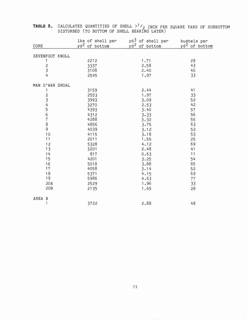
TABLE 8.
CORE
CALCULATED QUANTITIES OF SHELL >1/2 INCH PER SQUARE YARD OF SUBBOTTOM DISTURBED (TO BOTTOM OF SHELL BEARING LAYER)
lbs of shell per yd3 of shell per bushels per yd2 of bottom yd2 of bottom yd2 of bottom
SEVENFOOT KNOLL 1 2212 1. 71 29 2 3337 2.58 43 3 3108 2.40 40 4 2545 1.97 33
MAN O'WAR SHOAL 1 3159 2.44 41 2 2553 1.97 33 3 3993 3.09 52 4 3270 2.53 42 5 4393 3.40 57 6 4312 3.33 56 7 4288 3.32 55 8 4856 3.76 63 9 4039 3 � 12 52 10 4115 3.18 53 11 2011 L56 26 12 5328 4.12 69 13 3201 2.48 41 14 817 0.63 11 15 4201 3�25 54 16 5018 3.88 65 17 4058 3.14 52 18 5371 4.15 69 19 5986 4�63 77 20A 2529 1.96 33 20B 2135 1. 65 28
AREA B 1 3722 2.88 48
73

TABLE 9. DIGITIZED INFORMATION FROM FIGURE 6 AND CALCULATION OF AMOUNT OF BUSHELS FOR STUDY AREAS
DIGITIZED STUDY AREA (in2)
SEVENFOOT KNOLL 0.52 0.17
TOTALS 0.69
MAN O'WAR SHOAL 0.02 1.45 1. 47 1.06 2.62 0.30 0.08
TOTALS 7.04
SIXFOOT KNOLL
yd2
157,300 51 ,425
208,725
6050 438,625 444,675 320,650 792,550
90,750 24,200
2,129,600
8.52 2,577,300
AREA B 7.95 2,404,875
bushels/yd2 of bottom
30 to 40 (ave 35) >40
bushels
5,505,500±786,500 2,057,000 minimum 7,562,500±786,500
minimum amount of bushels 6,776,000 maximum amount of bushels 8,349,000
<20 121 ,000 mInimUm <30 13,158,750 minimum 30 to 40 (ave 35) 15,563,625±2,223,375 40 to 50 (ave 45) 14,429,250±1,603,250 50 to 60 (ave 55) 43,590,250±3,962,750 60 to 70 (ave 65) 5,898,750±453,750 >70 1,694,000 minimum
94,455,625±8,243,125
minimum amount of bushels 86,212,500 maximum amount of bushels 102,698,750
? ?(*)
48 ?(*)
Figure 6 parameters used in calculations; chart scale = 1 :20,000 1 in = 550 yds
(*) undetermined due to lack of coring data
74