oconee nuclear site, core operating limits report (colr). · cft boron concentration shall be...
TRANSCRIPT
AtDukeEr Power.
A Duke Energy Company
RON A. JONESVice PresidentOconee Nuclear Site
Duke PowerON01 VP / 7800 Rochester HighwaySeneca, SC 29672
864 885 3158864 885 3564 fax
April 14, 2005
U. S. Nuclear Regulatory CommissionDocument Control DeskWashington, D. C. 20555
Subject: Oconee Nuclear Site Docket No. 50-269Core Operating Limits Report (COLR)
Gentlemen:
Attached, pursuant to Oconee Technical Specifications 5.6.5, isan information copy of a revision to the Core Operating LimitsReport for Oconee Unit 1, Cycle 23, Rev. 25.
Very truly yours,
•7 fI (?c v7 1Jba
R. A. Jones Site, Vice PresidentOconee Nuclear Site
Attachment
- Do�
www. dukepower. corn

NRC Document Control DeskApril 14, 2005Page 2
xc w/att: Mr. W. D. Travers, ''Regional AdministratorU. S. Nuclear Regulatory Commission, Region II
Mr. L. N. Olshan,-'-Project ManagerOffice of Nuclear. Reactor.Regulation
Mr. Mel Shannon",Senior Resident Insp'ector :Oconee, Nuclear SiteSe '

DISPOSmON OF THE ORIGINAL DOCUMENT WILL BE TOP RTY SuperRush THE TRANSMITTAL SIGNATURE UNLESS RECIPIENT ISPRIORITY OTHERWISE IDENTIFIED BELOW
1) 00620 DOC MGMT MICROFILM EC04T2) 00813 DOC MGMT EC04T ORIGINAL3) 06358 ONS REGUL COMPLANCE ON03RC4) 06700 ONS MANUAL MASTER FILE ON03DM5) 06937 R R ST CLAIR EC08G
Duke Power CompanyDOCUMENT TRANSMITTAL FORM
REFERENCE
NUCLEAR GENERAL OFFICE
OCONEE NUCLEAR STATION
WORK ITEM: EXEMPTION M-5
RECORD RETENTION: 003587
RESP GROUP: NE
OCONEE I CYCLE 23
CORE OPERATING LIMITS REPORTS,
Page 1 of 1
Date: 04107/05
Document Transmittal # DUK050960022
QA CONDITION Ei Yes F NoOTHER ACKNOWLEDGEMENT REQUIRED . Yes
IF QA OR OTHER ACKNOWLEDGEMENT REQUIRED, PLEASEACKNOWLEDGE RECEIPT BY RETURNING THIS FORM TO:
Duke Power CompanyP.O. Box 1006Energy CenterEC04TCharlotte, N.C
Rec'd By
Date , I q, . , , � I4. I. *_.._ _._ _._ _| i
DOCUMENT NOI I ~ 1 i -
QA COND REV #1 DATE DISTR CODEI . I . I I,, . I L ' - . . . . . II I . I .. I I I . II .1, 2 3 .4 1, 5 6 7 .8 9 10 11 12 113 14 15 | TOTAL
, 4- .. .. I - I I'_I_ _1_i_ _'_ _I'_I'_ _I
ONEI-0400-050 0 1 ;: i; t 'S: ;:.... . ., ,,, a ...
,: . i Jo ., .f- .
: hi .. 4, 1 ..''
:
;: '
025 '04/07/05,4- i ; ' ,
I, I;:I:~ ~ . I ,
i:I :I .. i i, ,-....
NOMD-27 Vl ."] q .- r
.;j i
VI1:',
10A
VI 4
FOR INFCRN~AT IotrILY
I IREMARKS: DUKE
DOCUMENT RELEASE EXEMPT FROM NUCLEAR MODIFICATION PROGRAM. THOMAS C GEER
NUCLEAR STATION ENGR MANAGER
GS-SVP NUCLEAR SUPPORT
BY:
J W SIMMONS JWS/TER EC08H

.ONEI-0400-50 Rev 25Page 1 of 33
Duke Power Company
Oconee 1 -Cycle 23
Core Operating Limits Report
QA Condition 1
Prepared By L. D. McClain /2.uc 9- A&'n YI'1
Checked By: J. D. Forster
CDRBy: T.P.-Yadon / n-,tZ.
Date: X (Apr Oo5
Date * -&Apr, aI
Date: /( /(O ,/ o
Date: /4 D
7 7 1-~ d
Approved By: R.-R. St.Clair

: 6Docu'ment No. / Rev. ONEI-0400-50 Rev. 25-Date April 6, 2005Page No. Page 2 of 33
INSPECTION OF ENGINEERING INSTRUCTIONS
Inspection Waived By: , IiP eag(Sponsor)
Date: i//s
CATAWBA
InspectionWaived
MCE (Mechanical & Civil) : -Inspected By/Date:
RES (Electrical Only) ' Z] Inspected By/Date: - _-_;
RES (Reactor) El Inspected By/Date: :
MOD L Inspected By/Date:
Other ' '_)_'_:_____ )'' Inspected By/Date:
:-CONEE
InspectionWaived
MCE (Mechanical & Civil) 'Inspected By/Date:
RES (Electrical Only) -Inspected By/Date:::RES (Reactor) -,Inspected By/Date: _ _ _ __:
MOD I. : nspected By/Date: -_:_.
Other ( ) [ Inspected By/Date: :
-MCGUIRE
InspectionWaived
MCE (Mechanical & Civil) ' ; Inspected By/Date: '-_-__'.;______________________
RES(Electrical Only) [] InspectedBy/Date:: '-_:
RES (Reactor) [3 Inspected By/Date: _______________-__
MOD [l Inspected By/Date: __ _:
Other ( -E)l______-,_. -, Inspected By/Date: _

:1
ONEI-0400-50 Rev 25Page 3 of 33
Oconee 1 Cycle 23
Core Operating Limits Report
Insertion Sheet for Revision 25
This revision is not valid until the end of operation for Oconee 1 Cycle 22.
Remove these Revision 24 pages I te Rev sion 25 pages
1 - 33 1-33
Revision Log
Effective Pages Pages., Pages Total EffectiveRevisionn Date -Revised -.'Added:,- Deleted Pages
-Oconee 1 Cycle 23 revisions below25 - Apr 2005 = 1 -33 - - 33
Oconee 1 Cycle 22 revisions below . -
:-24 Mar2005 - 1-3,5 - - 3323 Feb 2005 1-4,6 - - 3322 Dec2004 - 1-3,30 : .--, . - 3321 Feb 2004 14,6 -33
20 Nov2003 1 -32 33 - 33
Oconee 1 Cycle 21 revisions below-19 ~Aug'2003 1,2, 3 1 -a -32
18 Apr2002 - 1,2,4 - - -32-17 Mar2002. 1-31- -32- - 32
Oconee 1 Cycle 20 revisions below - - -May2001 1 -4- 31
15 Nov2000 1 -31 - - 31

ONEI-0400-50 Rev 25Page 4 of 33
Oconee I Cycle 23
1.0 Error Adjusted Core Operating Limits
The Core Operating Limits Report for 01C23 has been prepared in accordance with the requirements
of TS 5.6.5. The core operatirig limits within this report have been developed using NRC
approved methodology identified in references 1 through 1 1. The RPS protective limits
and maximum allowable setpoints are documented in references 12 through 14. These limits are validated for
use in 01C23 by references 15 through 16.'- The Oi23 analyses assume a design flow of 107.5% of
88,000 gpm per RCS pump, radial local peaking (FAh) of 1.714, and axial peaking factor (Fz) of 1.5,
and an EOC (< 100 ppmB) Tavg reduction of up to 100F provided 4 RCPs are in operation and Tavg
does not decrease below 5690F.
The error adjusted core operating limits included in section 1 of the report incorporate all necessary
uncertainties and margins required for operation of the 01C23 reload core.
1.1 References
1. Nuclear Design Methodology Using CASMO-3 / SIMULATE-3P, DPC-NE-1 004P-A, Revision 0,
SER dated November 23,1992.
2. Oconee Nuclear Station Reload Design Methodology II,-DPC-NE-1002A, Revision 1,
SER dated October 1,1985.
.3. Oconee Nuclear Station Reload Design Methodology, NFS-1001A, Revision 5,
SER dated December 8, 2000.
4. ONS Core Thermal Hydraulic Methodology Using VIPRE-01, DPC-NE-2003P-A, Revision 1,
SER dated June 23,2000.
5. Thermal Hydraulic Statistical Core Design Methodology, DPC-NE-2005P-A, Revision 2,
SER dated June 8,1999.
6. Fuel Mechanical Reload Analysis Methodology Using TACO3, DPC-NE-2008P-A,
Revision 0, SER dated April 3,1995. -
7. UFSAR Chapter 15 Transient Analysis Methodology, DPC-NE-3005-PA, Revision 2,
SER dated September 24, 2003.
8. DPC-NE-3000P-A, Thermal Hydraulic Transient Analysis Methodology, Rev. 3,
SER dated September 24, 2003.
9. BAW-10192-PA, BWNT LOCA - BWNT Loss of Coolant Accident Evaluation'Model for
Once-Through Steam Generator Plants, SER dated February 18, 1997.
10. BAW-10164P-A, Rev. 4, RELAP51MOD2-B&W - 'An'Advanced Computer Program'for Ught Water
Reactor LOCA and Non-LOCA Transient Analysis", SER dated April 9, 2002.
11. BAW10227-PA, Evaluation of Advanced Cladding and Structural Material (M5) in PWR Reactor Fuel,
SER dated February 4, 2000. -
12. RPS RCS Pressure & Temperature Trip Function Uncertainty Analyses and Variable Low Pressure
Safety Limit, OSC-4048, Revision 4, January 2001.-
13. Power Imbalance Safety Limits and Tech Spec Setpoints Using Error Adjusted Flux-Flow Ratio of
1.094, OSC-5604, Revision 2, October 2001.
14. ATc and EOC Reduced Tavg Operation, OSC-7265, Rev. 1, Duke Power Co., June 2002.
15. 01C23 Maneuvering Analysis, OSC-8658, Revision 1, April 2005.
16. 01 C23 Reload Safety Evaluation, OSC-871 8, Revision 0, April 2005.
ONEI-0400-50 Rev 25Page 5 of 33
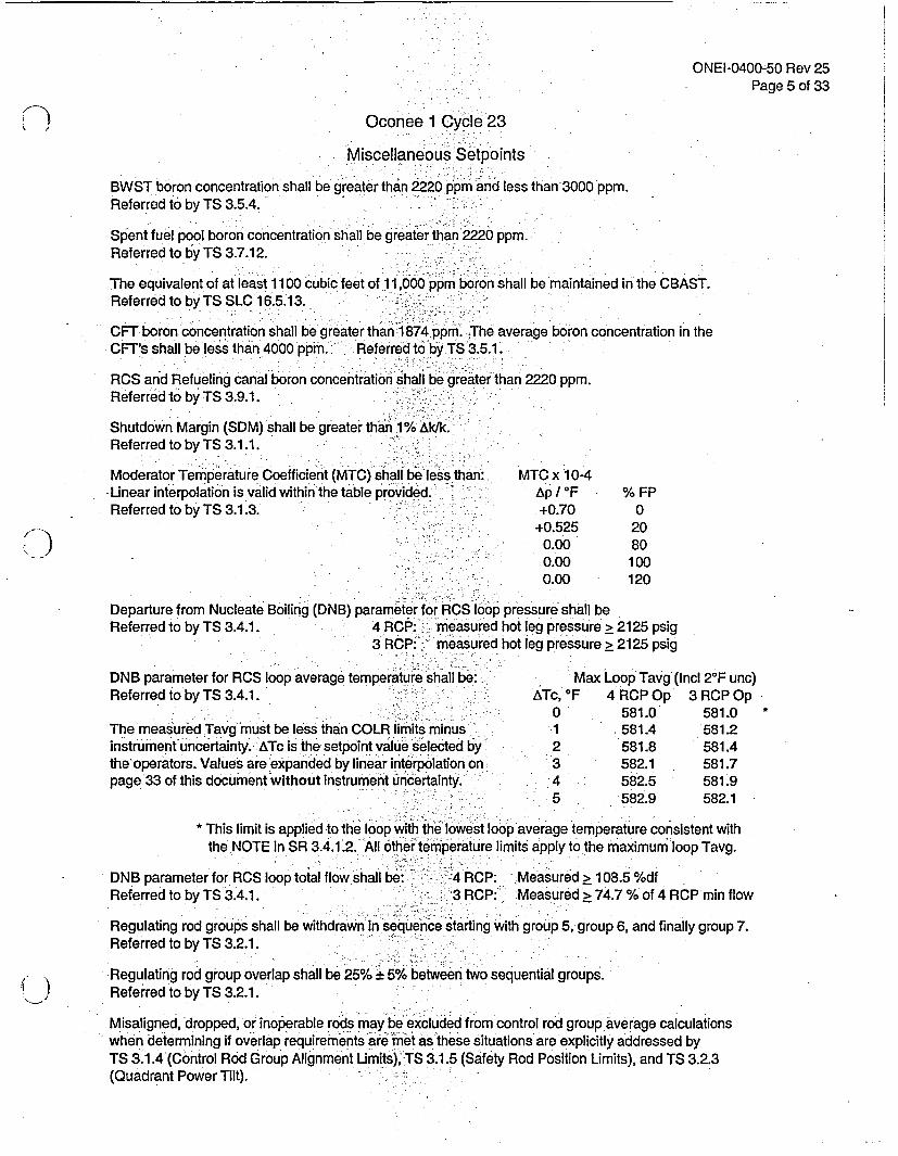
Oconee 1 Cycle 23
Miscellaneous Setpoints
BWST boron concentration shall be greater than 2220 ppm and less than 3000 ppm.Referred to by TS 3.5.4.
Spent fuel pool boron concentration shall be greater than 2220 ppm.Referred to by TS 3.7.12.
The equivalent of at least 1100 cubic feet of 11,000 ppm boron shall be maintained in the CBAST.Referred to by TS SLC 16.5.13.
CFT boron concentration shall be greater than 1874 ppm. The average boron concentration in theCFT's shall be less than 4000 ppmi. Referred to by TS 3.5.1.
RCS and Refueling canal boron concentration shall be greater than 2220 ppm.Referred to by TS 3.9.1.
Shutdown Margin (SDM) shall be greater than 1% Ak/k.Referred to by TS 3.1.1.
Moderator Temperature Coefficient (MTC) shall be less than: MTC x 10-4
Unear interpolation is valid within the table provided. - Ap/ F % FP
Referred to by TS 3.1.3. +0.70 0
+0.525 20
0.00 80
0.00 100
0.00 120
Departure from Nucleate Boiling (DNB) parameter for ROS loop pressure shall be
Referred to by TS 3.4.1. 4 RCP:- measured hot leg pressure > 2125 psig
3 R CP:- measured hot leg pressure > 2125 psig
DNB parameter for RCS loop average temperature shall be: Max Loop Tavg (Incl 20 F unc)
Referred to by TS 3.4.1. ATc, 'F 4 RCP Op 3 RCP Op
0 581.0 581.0 *
The measured Tavg must be less than COLR limits minus 1 581.4 581.2
instrument uncertainty.- ATc is the setpoint value selected by 2 581.8 581.4
the operators. Values are expanded by linear interpolation on, 3 582.1 581.7
page 33 of this document without instrument uncertainty.4 582.5 581.9
5 582.9 582.1
* This limit is applied to the loop with the lowest loop average temperature consistent with
the NOTE in SR 3.4.1.2. All other temperature limits apply to the maximum loop Tavg.
DNB parameter for RCS loop total flow shall be: - 4 RCP: Measured > 108.5 %df
Referred to by TS 3.4.1. 3 RCP: Measured > 74.7 % of 4 RCP min flow
Regulating rod groups shall be withdrawn in sequence starting with group 5, group 6, and finally group 7.
Referred to by TS 3.2.1.
Regulating rod group overlap shall be 25% + 5% between two sequential groups.
Referred to by TS 3.2.1.
Misaligned, dropped, or inoperable rods may be excluded from control rod group average calculations
when determining if overlap requirements are nmet as these situations are explicitly addressed by
TS 3.1.4 (Control Rod Group Alignment Umits), TS 3.1.5 (Safety Rod Position Limits), and TS 3.2.3
(Quadrant Power Tilt).

ONEI-0400-50 Rev 25Page 6 of 33
Oconee 1 Cycle 23
Steady State Operating Band
Rod Index APSR %WDMi Max Min Max
292t5 300 30 40
EFPD
0 to EOC
Core Power Level, %FP
Full Incore
-Out of Core
Backup Incore
Quandrant Power Tilt Setpoints
Steady State Transient30-100 0-30 30-100 0-30
3.50 7.32 6.82 9.10
2.33 6.09 5.63 7.72
2.25 3.87 3.63 4.81
Referred to by TS 3.2.3
Maximum0 - 100
16.26
14.22
10.07
-Correlation Slope'(CS)
-1.15
Referred to by TS 3.3.1 (SR 3.3.1.3).
ONEI-0400-50 Rev 25
Page 7 of 33
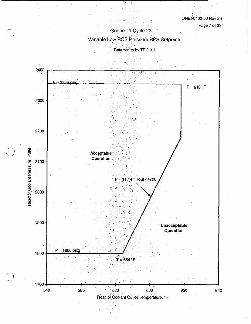
Oconee 1 Cycle 23
Variable Low RCS; PressureRPS Setpoints
Referred to by TS 3.3.1
2400
2300
2200
co05M
<' 2100Mcn
0na)
a.C:
000
2000
0
1900
1800
1700 _-540 560 - - 580 600
Reactor Coolant Outlet Temperature, OF
620 640

ONEI-0400-50 Rev 25Page 8 of 33
- Oconee 1 Cycle 23
RPS Power Imbalance Setpoints
% FP -
4 Pumps90.4 -
-107.9 --:107.9:1 90.4 -
0.
% Imbalance
-33.0-33.0-14.414.4.33.0.33.0
-33.0-33.0-14.414.433.033.0
3 Pumps -̂ . .- 0 ,:',0 63.1-
- 80.6-,E 0 80.6--: 63.1
0 .0 -
Maximum Allowable RPS Power Imbalance Limits
% FP-
4 PumpsX;90.0-109.4109.4 -9.0
:0
% Imbalance
-35.0-35.0-14.414.435.035.0
-35.0-35.0-14.414.435.035.0
3 Pumps 0'
-62.381.781.762.3
0
ONEI-0400-50 Rev 25Page 9 of 33
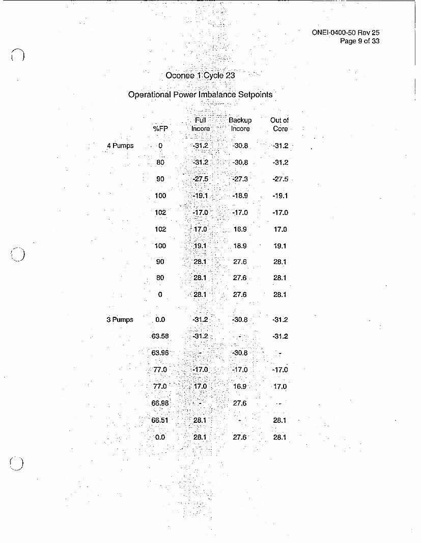
e C le 23
Operational Power Imbalance Setpoints
Full Backup Out of
%FP mncore. Incore Core
4 Pumps -0 -31.2 -30.8 -31.2
-80 -31.2 -30.8 -31.2
90 -2~7.5`- -27.3 -27.5
100 -1 -18.9 -19.1
102 -7.0 -17.0 -17.0
102 -17.0 -!16.9 17.0
100 19.1; 18.9 19.1
9 0 28.1 ,27.6 28.1
80 28.1 27.6 28.1
0 28.1 27.6 28.1
3 Pumps 0.0 -31.2 .8 -31.2
63.5 -312 -- 31.2
63.96- ~ -- 30.8-
77.0, -7. -17.0 -17.0
77.0- ~ -17.0 16.9 17.0
66.98 27.6
66.51 28.1 28.1
0.0 28.1 27.6' 28.1

ONEI-0400-50 Rev 25Page 10 of 33
Oconee 1 Cycle 23
Operational Power Imbalance Setpoints
Operation with 4 RCS Pumps, BOC to EOC
% FP RPS Trip . .Full lnoore Alarm I Out of Core Alarm
107.9
107106
105
104103102101
100
: 99989796
95
94939291
90.40
90
89888786
85
84838281
80
0
-14.40
-15.36-16.42
-17.48
-18.55-19.61-20.67-21.73
-22.80
-23.86-24.92-25.99-27.05
-28.11
-29.17-30.24-31.30-32.36-33.00
-33.00
-33.00-33.00-33.00-33.00
:-33.00
-33.00-33.00-33.00-33.00
-33.00
-33.00
14.40
15.3616.42
17.48
18.5519.6120.67
-21.73
22.80
23.8624.92-25.9927.05
28.11
29.1730.2431.3032.3633.00
33.00
33.0033.00-33.00-33.00
33.00
-33.0033.0033.0033.00
33.00
33.00
-- 17.00 ''''-18.05
--19.10,
-19.94--20.78"-21.62-22.46-
-23.30:
-24.14,;-24.983-25.82 2;-26.66--
' -27.16
--27.50
-27.87-28.24~-28.61-28.98
-29.35 0
-29.72-30.09-30.46--30.83
--31.20
-31.20
17.0018.05
19.10
20.0020.9021.8022.70
23.60
24.5025.4026.3027.2027.74
28.1 0
-28.10-28.1028.1028.10
28.10
28.1 028.1 028.1028.10
28.10
28.10
-17.00-18.05
-19.10
-19.94-20.78-21.62-22.46
-23.30
-24.14-24.98-25.82-26.66-27.16
-27.50
-27.87-28.24-28.61-28.98
-29.35
-29.72-30.09-30.46-30.83
-31.20
-31.20
17.0018.05
19.10
20.0020.9021.8022.70
23.60
24.5025.4026.3027.2027.74
28.10
28.1028.1028.1028.10
28.10
28.1028.1028.1028.10
28.10
28.10
% FP RPS Trip j - Full Incore Alarm J Out of Core AlarmI ' , I : h

ONEI-0400-50 Rev 25Page 11 of 33
Oconee 1 Cycle 23
Operational Power Imbalance Setpoints
Operation with 3 RCS Pumps, BOC to EOC
% FP I RPS Trip " I Full Incore Alarm Out of Core Alarm
80.6
80'
7978
77.076
75
74737271
70
696867
- 66.566
65
6463.5863.1636261
60
0
-14.40
-15.04
-16.10--17.16-18.23-19.29
-20.35
-21.41-22.48-23.54-24.60
-25.67
-26.73-27.79w-28.85-29.37'-29.92
-30.98
-32.04-32.49-33.00-33.00-33.00-33.00
-33.00
-33.00
14.40
15.04
16.1017.1618.2319.29
20.35
21.4122.4823.5424.60
25.67
26.7327.7928.8529.3729.92
30.98
32.04032.49
-33.0033.00
.33.0033.00
33.00
33.00
- -17.00-18.06
-19.12
-20.18, -21.23-22.29-23.35
-24.41
-25.47:i,26.53
--27.58tr>-28.1 0- X-28.64
-29.70
-'-30.76-31.20-31.20-31 20-31.20-31.20
-- 31.20 '0
'-31.20
: ,17.0018.06
19.12
20.18- 21.23-22.29' 23.35
24.41
'25.4726.53
'27.5828.10 -
28.10
28.10
:28.10.28.1028.1028.1 028.1028.10
28.10
28.10
-17.00-18.06
-19.12
-20.18-21.23-22.29-23.35
-24.41
-25.47-26.53-27.58-28.10-28.64
-29.70
0- -30.76-31.20-31.20-31.20-31.20-31.20
-31.20
-31.20
17.0018.06
19.12
20.1821.2322.2923.35
24.41
25.4726.5327.5828.1028.10
28.10
28.10
28.1028.1028.1028.10
28.10
28.10
% FP I - RPS Trip [-' Full In*ore Alarm Out of Core Alarm

Oconee 1 Cycle 23
RPS Power Imbalance Setpoihts
Referred to byTS 3.3.1
Thermal Power Level, %FP
120 -
ONEI-0400-50 Rev 25
Page 12 of 33
M2 = -0.941
(33.0,90.4)
(-14.4,107.9)
M1=0.941Acceptable 4
(-33.0,90.4) (-14.4,80.6)
100 -
(14.4,107.9)
:(14.4,80.6)
-: ,- . . I , I . - -.
mp OperationI - I - , . - ,
(-33.0,63.1)
.... .
-- 0: S--,:-.: -:
= . .
- .4 .
. f
: - .... :w.f. -
: .... . - f;.
. . E
- -0 60 -. ; .
. .
: . f ',.-
Acceptable 3 or 4 Pui. .... .
* ,; . ..'. .
L .; .
* ;
: --- 40-.. o
f . .... .... .
. . ..
, 4 ...
: f f C .. .
: - .:-: f S.
. .
-. V-
. ., . .-
: t --: 20 :-: .. ... .. f| - -: . -: . .; - - .:n. - , LC
, - .f, : . -. ,
,,
- - ', - ' : . . :':
, -
.
. ' :.
' :
: - R n
(33.0,63.1)
rnp Operation
,0:
. * . ! . . , ov .
-40.0 -30.0 -20.0 -10.0 ,0.0 ' 10.0
:Percent Power Imbalance
20.0 30.0 40.0

/ -I-)*
. Oconee 1 Cycle 23Imbalance Setpolnts for 4 Pump Operation, BOC to EOC
ONEI-0400-5D9v 25
Page 13 of 33
110I
100RPS Trip Setpointm E-- - - ~ -I _. I _ IIncore & Outcore Alarm RPS Trip Setpoint:
. . . . . . . . . .
90
I"807
70U1)O B
o :3
u-,
c ,a)
U)EL
60
5
40
30
20
10
-4-40
--35
--30, -25
- :-20 -15 -10 -5 0 5
v a v a10 15 20 ' 25
_ I
30 .: 35 40
Percent Axial Imbalance

.Oconee 1 Cycle 23ONEI-0400-50 A25
Page 14 of 33
Imbalance Setpoints for 3 Pump Operation, BOC to EOC
110
100
90
tRPS Trip Setpoint RPS Trip Setpoint _1 II I li t I __II_
80
l o I I I I * I t Arm : I I:Inco're & OUtcore Alarm70
1_
0
CLj0 . 60L, , . E
a) 050I .-Qi,
40
ann
20
10
0 9-40 -35
* a 5 - w-30 -25 -20 -15 -10 -5 0 5 10 15 20 25 30 35 40
Percent Axial Imbalance

ONEI-0400-50 Rev 25Page 15 of 33
Oconee 0Cycle 23-,
Operational Rod Index Setpoints
RI Insertion Setpoint%FP No Iop Rod 1 Inop Rod
4 Pumps
3 Pumps
102.0
100.0
90.0
80.0
50.0
48.0
15.0
13.0
5.0
3.0
2.8
0.0
77.0
75.0
50.0
48.0
15.0
13.0
5.0.
3.0
2.8
0.0
261.5
261.5
261.5
.1 95.2
291.5
7116.5
21.5-
0.0
255.5
:251.5
-201.5
:195.2
91.5
:76.5'
- 16.5
1.5 '
0.0
0.0
283.4
281.5
271.9
262.3
233.4
231.5
--165.5
-161.5
93.5
76.5
74.8
51.0
'285.2
281.5
235.2
231.5
165.5
161.5
93.5
76.5
74.8
51.0
RI WithdrawalSetpoint
300
300
300
300
:300
300
300
300
300
300
300
300
300
300
- 300
.300
300
300
300
300
300
300
ONEI-0400-50 Rev 25Page 16 of 33
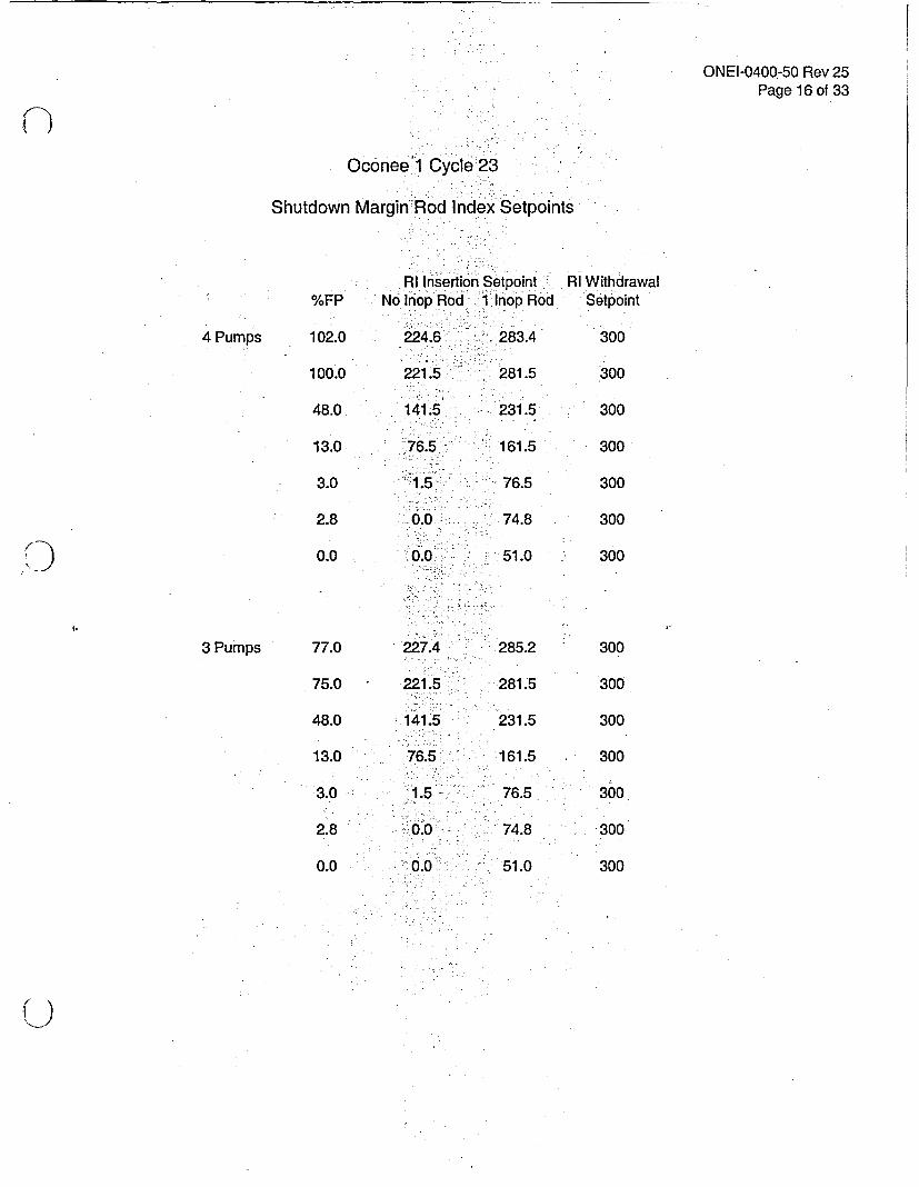
Oconee1 Cycle 23Shtdw- d...,r d St
Shutdown Margin-Rod In(dex Se points
4 Pumps
3 Pumps
%FP
102.0
100.0
48.0
13.0
3.0
2.8
0.0
77.0
75.0
48.0
13.0
3.0
2.8
0.0
RI Insertion SetpointNo Inop Rod 1 inop Rod
224.6- 283.4
221.5:: 281.5
141.5 231.5'
76.5 161.5
1.5 76.5
0.0 74.8
'-0.0 51.0
RI WithdrawalSetpoint
300
300
300
300
300
300
300
300
300
300
300
300
300
300
227.4
221.5
141.5
76.5
1.5
0.0,
0.0
285.2
281.5
231.5
161.5
76.5
74.8
51.0
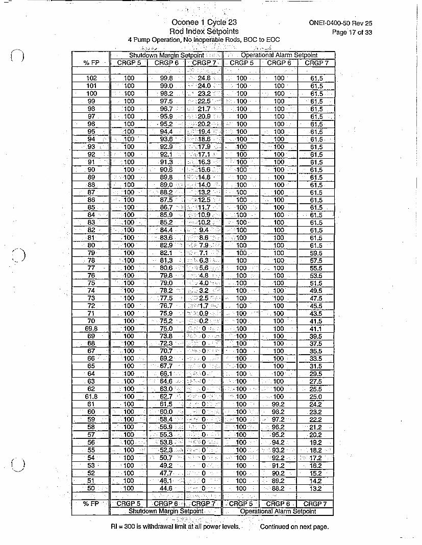
Oconee 1 Cycle 23Rod Index Setpoinrts
4 Pump Operation, No Inoperable- Rods, BOC to EOC
ONEI-0400-50 Rev 25Page 17 of 33
- '.�- I-1
Shutdown Margin etPoint - .IOperational Alarm etpoint,%FP CRGP 5 CRGP 6 ~CRGP7-7 CRGP5 CRGP 6 CRGP 7
102 100 99.8 24.8 1 00 100' 61.5101 100 - 99.0 240100 100 61.5100 100 98.2 23.2-: 100 100 61.5,99 100 97.5 22.51- 100 I 100 61.598 100 96.7 21.7 -100 .100 ~ 61.597 10 95.9 20.9 1 00 100 61.596 100 -95.2 -20. 2 100 1061.595 10 94.4 1 9.4 100 100 61.5
94100 93.6 18610100 61.593- 100 92.9 17.9 100 1061.5
92 100 92.1 -:117.11 100 100 61.591 :100 913 16.3 100 100 61.5
90100 90.6 - 15.6 100 100 61.589 - 100 89.8 148101061.5
88100 89.0 -14.0 100 100 61.587 :100 88.2 13210100 61.586 10 87.5 12.5 100 100 61.'585 100 86.7 11.7 100 100 61.584 100 85.9 110.9 100 100 61.583 -::100 85.2 10210 100 61.582 .10 84.4 9410100 61.581 100 83.6 8.6 -100 100 61.580 10 82.9: 7.9 100 100 61.579 0082.1 z- 7.1 100 100 59.578 1 00 81.3 6.3: 100 100 57.577 100 80.6 5.6 100 100 55.576 -100 79.8 -- 4.8.f' 100 100 53.575 100 79.0 .- 4.0 100 100 51.574 100 78.2 ~ 3.2- 10 100' 49.573 10 .775 .5 100 100 47.572 .100 '76.7 -1.7 100 100 45.571 10 75.9 0O.9 100 1043.570 :100 75.2 1-1~0.2 ~ 100 100 41.5
69.8 100 75.0 '0 --- 100 100 41.169 100 73.8 0: 100 100 39.5
68100 72.3 ~ 0 100 100 .37.5'67 100 70.7 0100 100 35.566r 100 69.2 0 '100 100 33.565 100 67.7 0oo 10 0 1.564 100 66.11010 0 29.563 . 100 64.6 -0 1 00 100 27.562 100 63.0 0 100 1025.5
61.8 -100 6.W 100 100 2.61 .100 61.5 0' :100 99.2 2.
60 10 60.0 0J10 98.2 23.259 10 5.40 0 97.2 2.
58 :100 56.9 0 100 96.2 2.57 '100 :55.3 0 :100 -95.2 20.256 10 5. 010 -94.2 19.255 100 -52.3 010011 932' 18.254 .100 50.7 0 100 -92.2 17.253 10 49.2 -0 100 91.2 16.252 100 47.7 - 0100 90.2 15.251 100 4610 100 -89.2 14.250 100 44.6 0-_~ 100 88.2 13.2
%FP CRGP5 RG s CRP CGP5-CRFGP6.CRP______ Shutdown Margin Setpoint. Operational Alarm Setpoint
RI = 300 is withdrawal limit at 'all power levels. Cotneonexpa.Continued on next page.

Oconee 1 Cycle 23Rod Index;Setpoints
4 Pump Operation, No Inoperable Rods, BOC to EOC
ONEI-0400-50 Rev 25Page 18 of 33
Shutdown Margin Setpoint Operational Alarm Setpoint%FP CRGP5 CRGP6 -CRGP7 CRGP 5 CRGP6 -CRGP7
49 -100 43.0 0 100; -86.7 11.748 100 41.5 0 - 100 85.1 10.147 100 39.6 0 100 -83.5 8.546 100 82.0 7.045 100 35.9 0 100 80.4 - 5.444 100 34.1 0 100 78.8 3.843 100 32.2 0 -- :' 100 . 77.2 2.242 100 30.4 0 100 75.7 0.7
41.6 100 29.6 0-O 100 75.0 041 .100 28.5 0 100 73.2 0.40 100 26.6 0 -100 70.1 0
39.1 -100 25.0 - 0 -100 67.3 039 99.9 24.9 0 100 -66.9 038 99.0 24.0 0- -100 63.8 037 98.0 -23.0 -0- 100 60.6 036 97.1 22.1 0 100 57.5 035 - 96.2 21.2 0 100 54.3 034 -95.2 20.2 0 -100 51.2 033 94.3 19.3 0 100 48.1 032 .93.4 18.4 0 100 44.9 031 92.5 17.5 0 100 41.8 030 91.5 16.5 0 100 38.6 029 - 90.6 15.6 0 100 35.5 028 89.7 14.7 0-- 100 32.4 027 88.8 13.8 0 100 29.2 026 87.8 12.8 - -0 100 26.1 0
25.7 87.5 12.5 5-0 - 100 25.0 025 86.9 11.9 0 99.0 24.0 024 86.0 - 11.0 0 97.4 22.4 023 85.0 -10.0 - 0 95.8 20.8 022 84.1 9.1 0 :94.2 19.2 021 83.2 8.2 0 92.7 17.7 020 82.2 7.2 0 91.1 16.1 019 81.3 6.3 0 89.5 14.5 018 80.4 5.4 0 88.0 13.0 017 - 79.5 4.5 0 86.4 11.4 016 78.5 3.5 - O,-0 :;84.8 9.8 015 - 77.6 2.6 0 0= '83.2 ; 8.2- 014 76.7 1.7 0 79.5 - 45 013 75.8-- 0.8 0 758 0.8 0
12.8 -75.0 0 0 - ; -75.0 0 012 :69.0 0 0 69.0- 0 011 61.5 0 0 61.5 0 0-10 - -54.0 0 0 54.0 : 0 09 . 46.5 0;:-0 - 0 46.5 0 08 39.0 0 0 .39.0 07 31.5 0--?- 0---o 31.5 0 06 24.0- 0 0 24.0 0 05 -16.5 ,0 0 16.5 0 04 9.0 0 0 9.0 0 03 1.5 - 0 0- 1.5 0 02.8 0 0 0 02 0 0 0 0 0 010 0 0 0 0 0
0 0 0 0 0 0o 0
%FP CRGP5 CRGP6 --CRGP7 CRGP5 CRGP6 CRGP7. Shutdown Margin Setpoint Operational Alarm Setpoint
RI =300 is withdrawal limit at all power levels.

Oconee 1 Cycle 23.Rod Index Setpoints
3 Pump Operation ,No Inoperable Rods, BOC to EQO
ONEI-0400-50 Rev 25Page 19 of 33
Shutdown Marqin Sepoint'- Oper tonal Alarm Setpoint% P CRGP 5 CRGP 6 CRGP 7 CRGP 5 CRGP67 CRGP 7
77 100 100 '27.4- 1 00 100 55.576.2 100 100 -25.0-' 100 100 53.976- 100 .99.7 24.7 10100 53.575 10 - 9.232100 100 51.5
74 100 96.8 218 0 100 49.573 100 95.3 -~20.3 100 1047.572 100 .93.8 1 8.8 10100 45.571 100 92.3 1 7.3 100 100 43.570 100 90.8 -15.8 100 10 4.69 1089.4 -14.4 -100 100 39.568 100 87.9 129100 100 - 37.567 10 64 11.4 100 1100 35.566 100 84.9 9.9' 100 1 00 33.565 1 00 83.4 .-8.4 1 00 100 31.564 100 -82.0 70100 100 29.5.63 :100 -80.5 5.5 10100 27.5
62100 79.0 '40100 7 100 2.61.8 -100 78.6 3.6 100 100.- 25.06 1 .100 77.5 - 2.5 ~ 100:- 99.2 24.260 100 76.0 -101009823.
59.3 100 75.0 0 100 97.6 22.659. 100 74.1 0100 97.2 22.258 -100' 71.1 0 -100 96221.257 100 68.2 :0 100 95.2 20.256 -100 65.2 0100 94.2 19.255 100 62.2 0- 100 93.2 18.254 100 59.3 0100 92.2 17.253 -100 56.3 0 100 91.2 16.252 '100 53.4 0O 100 90.2 15.251 .100 50.4 0 10 9214.250 ~~-100 47.4 '-0 100 -88.2 13.249 10 450- 100 86.7 11.748 100' 41.5 0 100 85.1 10.147 100' *39.6 0 100 83.5 - 8.546 100 37.8 0 100 82.0 -7.0
45 .100 35.9 -0100 80.4 5.444. -100 :34.1 0 100 7883.8
- 3100 32.2 . 0 722.2:42 ~ -100 30.4 0- 100 75.7 0.7
41.6 100 29.6' 0 .100 75.0 041 100 :28.5 0 10 73.2 040 -100 26.6, 0~- 1100 70.10
39.1 -100 25.0 0 - 100 673039 99.9 24.9 0 1j00 66.9 038 ~ 99 24.0 01063.8 037 9823.0 0100 60.6 036 97.1 - 210 100 57.5 035 96.2 21.2:- 0 100 54.3 034 95.2 20.2 0 - 100 51.2 033 94.3 19.3 0.- 100 48.1 032 93.4 -18.4 0 100 44.9' 031 92.5 17.5 0 100 41.8 030 91.5 16.5 0 100 38.6 0
2990.6 15.6 0 100 35.5. 028 89.7 14.7 0 1 00: 32.4 0
% FP- CRGP 5 CRGP 6 7CRGP 7 CRGP 5 CRGP 6 CRGP 7_____ Shutdown Margin Setpoint - Operational Alarm Sepon
RI = 300 is withdrawal limit at all power levels. Cotneonexpa.Continued on next page.

IOconee 1 ,Cycle 23I.Rod Index Setpoints
3 Pump Operation, No Inoperable Rods, BOC to EQO
ONEI-0400-50 Rev 25Page 20 of 33
Shutdown Marqin Sepofint Operational Alarm Sepoint%FP CG5 CRGP 6 ~CRGP. -CRGP 5 CRGP 6. CRGP 7
27 88.8 13.8 0. 100 29.2 026. 87.8 12.8 0 00 26.1 0
25.7 87.5 12.5 -0 100 25.0 025 86.9 -11.9, ~0 99.0 24.0 0
24 8. 100 -97.4 22.4 023 85.0 10.0' ~ 0 95.8 20.8 0
22 84.1 9.1 _0 94.2 19.2 0O21 83.2 8.2 0 927 17.7 020 82.2 -7.2 091.1 16.1 0
19 813 6.3 0 8Z9.5 14.5018 80.4 -5.4 0 88.0 13.0. 017 79.5 4.5 .0 86.4 11.4 0
16 78.5 3.5 0 8489.8 0
15 77.6 26 83.2 8.2 014 76.7 1.7 0 954.5 01 3 75.8 0.8 0-~ 75.8 0.8 0
12.8 75.0 0 0 7.12 69.0 0 0~- 69.0 0 011 61.50 0 61.5 0 0
10 54.0 0 -0 54.0 .0 0
9 46.5 0 0 46.5 0 08 39.0 0 039.0 0 0
7 31.5 00 3 1.5 0 0
6 24.0 0 024.0 0 0516.5 0 01 6.500
4 9.0 0 0 9.0 0 03 1 .5 0 0 .5 0 02.8 0 0 0 0 0 02 0 0 0 0 0 01 0 0 0 0 0 00 0 0 0 0 0 0
% FP CRGP 5 CRGP 6 -CRGP7 CRGPS 'CRGP 6 CRGP 7_____ Shutdown Margin Setpoint i--- Operational Alarm Setpoint
RI =- 300 is withdrawal limit at all power levels.

Ocornee 1 Cy~cle 23Rod Index' Setpoints
4 Pump Operation, 1 Inoperable Rod, BOC to EQO
ONEI-0400-50 Rev 25Page 21 of 33
Shutdown Marmin Sepoint -Operational Alarm Setpoint% FP :CRGP 5 CRGP 6 CRGP 7 CRGP 5 CRGP 6 CRGP 7
102 :100 100 -83.4 '100 100 83.4101 1100 00825100 100 82.510 .100 100 81.5 100 100 81.5-99 ~ 100 ~ 100 80.5 100 1 00 80.5
98100 100 ~ 79.6 -100 100 79.697 .100 l100-. 778.6 '100 100 -78.696 100 100 ,--77.7 100 100 77.795 100 100 76.7 100 100 76.794100 1 00 75.7 100 107.
93 .100100 74.8 100 100 74.892 -100 100 73.8 :100 100 73.891 :100 100. 72.8 .1001 100 72.990 100 100 71.9 10107.89 ~ 100 100 709100, 100 70.988 100 100 70.0: 100 100 - 70.0~87 100 100 -__69.0 10 1069.086 100 100 :,,68.0 100 100 68.185 100, 100O ',67.1 100 100 67.1.84 100 100 --66.1- 100 ~ 100 66.183 -100 '100 '6 5.2 100 100 65.2 -82 .100 100 _;~64.2 100 100 64.281 1 00 :100 63~".2 100 :100 63.380 100, 100 62.3 100 100 62.379 100 :100 613100 100 61.378 10100 ~ 60.3 100 100 60.477 100 100 ':;59.4 10100 59.476 -100 100 58.4 100058.47101057. 100 100 5.
74 100 100 56.5 100100 56.573 :100 .100 55.5 100. 100 565.72 100 100 54.6 100 100 54.671 :100 100 53.6 100 100 53.6
70 100 10 527 00 100 52.769 100 100 ~ 51.7 100 100 5.68 100, 100 -__50.7 - 100 100 50.7~67 100 100 49.8.- 100 100 49.8
66100 :100 48.8 1 00 :100 48.865100 10 .47.8 - :1 00 100 47.8
64 -100 -- 100 :_~46.9 100 -100 46.963 1 00 1 00' 45.9 .100 100 4.62 100 10 50100 100 - 45.061 :100 1 00 ~ 44.0 -100 100 44.060 100 -100 43.0: 100 100 43.059 100 04. - 100 100 4.,58 -100 :100 .'41.1' 100 100 41.157 100 -1 00 40.2: '100: 100 . 40.256 1010 39.2 1000- 39.255 100 100 38.2 10Q 100 38.254 _100 ~ 100 37.3 10-100 3.
53100 1 00 36.3 :100 -100 36.352 10100 35.3 100 100 35.351 100 100 34.4 - 100 100 34.450 ~ 100 100 ~ 33.4 100 100 33.449 100 100 ~ .32.5 100 '1032.548 100 10 .31.5,: 100 100 31.5
%P CRGP 5 CRISP6 CRGP 7 CRGP 5 -CRGP 6 CRGP 7Shutdown Margin Setpon . Operational Alarm Setpoint
RI = 300 is withdrawal limit at all power levels. Cotneonexpa.Continued on next page.

Oconee 1 Cycle 23,~II.Rod Index Setpoints
4 Pump Operation, ~1 In'operable Rod, BOC to EOC
ONEI-0400-50 Rev 25Page 22 of 33
Shutdown Margin SepitOperatonal Alarm Sepoint% FP CRGP.5 CRGP 6:CGP CRGP 5 CRGP 6 CRGP 7
47- 100 100 29.5 ~ 1 00 100 29.546 100 100 -27.5 100 100 27.545 100 100 25.5 100 1025.5
44.8 100 100 250 100 100 25.044 100 99.2 -24.2 100 99.2 24.243 100 98.2 -23.2, 100 98.2 23.2 -42 100 '97.2 222 10 97.2 22.2,41 100 -96.2 -21.2 -100 96.2 21.2
40100 `95.2 20.2 100 9520.39100 ~~94.2 192 10 94.2 19.2
38 100 ~ ~93.2 -18.2 100: 93.2 18.237 .10 922 1.00 92.2 17.236 100 912 16.2 1100 91.2 16.235 100 90.2 -15.2-:- 100 90.2 15.234 ~ 100 89.2 14.2 100 89.2 14.233 100 88.2 1 3.2 10 88.2 13.232 100' 87.2 -12.2 :100 87.2 12.2
31100 86.2 ~ -11.2, 100 86.2 11.230 :100 -85.2 10.2 100 85.2 1.29 '100 8429. 0 84.2 .228 -100 83.2 8.2100 83.2 8.2
27 10 822 72 10 82. 7.26 100 81.2 7.2 100 81.2 6.2
25, 100 80.2 52100 80.2 5.224 100 79.2 ,4.2 10 79.2 4.223 100 78.2 -3.2 100 78.2 3.222 100 77.2 2.2 -100 .77.2 2.221 100 -76.2 -1.2 :100 76.2 1.220 100 -75.2 -'-0.2 100 75.2 0.2
19.8 100 75.0 -0100 75.0 019 100 73.5 0 .100 73.5 018 100 71. - :100 71.'5 017 100 69.5 0 100 6950
16100 67.5 0 10 67.5 015 100 65.5 0 100 65.5 0
14100 63.5 0100 63.5 :013 100 61.5 0 106.12 100 53.0 0 - 0 300
11100 4450 - 100 44.5010 100 36.0-~ 0 100 36.0 09 100 27.5 0100 27.5 0
8.7 100 25.0 010 25.0 -0.8 97.0 22.0 0 97.0 22.0 07 92.8 117.8: 0 28 17.8 06 88.5 13.5 088.5, 13.5 0
584.2 9.2 0 8429204 8. 5.0 0~ 80.0 .5.0 03 75.8 0.8O 75.8: 0.8 0
2.8 - 75 0 0750 02 68 0 :0 68 0 01 59.5 0 0 59.5 ~ 0 00 51 -0 0 ~ 51 0 0
%FP CRGP 5 -CRGP 6 CRGP 7 CRGP 5 -CRGP 6 CRGP 7________ Shutdown Margin Setpoint --. Operational Alarm Setpoint
RI --300 is withdraw al limit at all power levels.

Oconee 1 Cycle 23Rod Inde-x Setpoints
.3 Pump Operation, 1 Inoperable Rod,' BOC to EOC
ONEI-0400-50 Rev 25Page 23 of 33
-Shutdwn Magin SepointOperational Alarm Setpin%FP CRGP 5 ~-CRGP 6 CRGP 7 CRGP5~ CRGP6 CRGP7
77 100 100 85.2 100 1085.276 100 100 83.4 100 1 00 83.475 100 100 81.5 10100 81.574 100 100 .-79.6 100 100 79.6
.73 100 100 77.8 :1 00 100 77.872 100 100 --:,75.9 -100 100 75.971 ~ 100 100 - .74.1 100 100 74.1~70 100 . 100 72.2 -100 100 72.2,-69 100 .1070.4 100 100 70.468 100 100 685100 100 68.567, -100 100 - 67100 100 66.766 ~ 100 100 -'64.8 10100 64.865 -100 100 63~.0 . 100 100 63.0
64100 100 ,61.1 100106.63 100 1059.3 10100 59.362 1 100 100 57.4 100 :100 57.461 100 100 .55.6 100 ~ 100 55.660 .100 100 53.7., T 100 100 53.759 -`100 100 51.9 100 100 -51.958 100 100 - 0010100 50.057 10100 -48.2 100 100 48.256 100 100 ~ ~46.3 100 .100 46.355 100 100 -44.5 100 100 44.554 100 -100 --- 42.6 100 100 42.653 100 100 1 4~0. 8 , -100 100 40.852 100 100 38.9 100 1038.951 100 .100 -~37.1 10100 37.1
50 100 100 35.2 100 100 35.249 100 -- 100 33.4 100 100 33.448 100 100 31.5 100 100 31.547 100 100 295100 100 29.546 100 100 -27.5 100027.545 100 100 25.5 100 100 25.5
44.8 100 .100 25.0 100 100 25.0~44 :100 99.2 ~ 24.2 100 99.2 :24.243 1098.2 23.2' ~ 100 98.2 2.
4109722100 097222.241 100 96.2 ~ 21.2 100 96.2 21.240 100 95.2 20.2 100 95220.239 100 94.2 19.2 100 94.2 19.238 100 93.2 189.2 -100- 93.2 18.2
37- 100 92.2: 17. 1 00 ~ 92.2 -17.2
36 :1 00 91.2 ~ 16.2 100 91.2 16.235 -100. 9. 15.2 ~ 100 90.2 15.234 .100 89.2 14.2- 100 89.2 14.233 100 -88.2 -13.2 100 -88.2 13.232 100 87.2 12.2 100 87.2 12.2:31 100 . 86.2 -11.2 1 00 86.2 11.230 -100 85.2 ~ 10.2 - 100 85.2 10.229- '100 84.2 92100 -8.9.2
28 :100 83.2 ~ 8.2 100 83.2 8.227 100 82.2 7.2 100 ~ 82.2 7.226 100 81.2 6.2 100 81.2 6.225 100 80.2 ~ :5.2 100 80.2 5.224 100 79.2 42100 79.2 4.2
%FP CRGP5 CRP R P- CRGP5 CRGP6 CRGP7_____ Shutdown Margin Setpoint - Operational Alarm Setpoint
RI = 300 is withdrawal limit at all power levels. Cotneonexpa.Continued on next page.

Oconee 1 Cycle 23Rod Index Setpoints
3 Pump Operation, 1 Inoperable Rod, BOC to EQO
ONEI-0400-50 Rev 25Page 24 of 33
Shutdown Margqin Sepoint Operational Alarm Sepoint% FP CRGP 5 CRGP 6 -- CRGP7L1 CRGP5 CRGP 6 CRGP 7.
23 '100 *7.23.2 -100 78.2 3.222 100 77.2 2.2 1 00 77.2 2.221 100. 76.2 1.2 100 76.2 1.220 .100 75.2 0.2 100 75.2 0.219.8 100 75.0 0100 75001 9 1073.5 0l~- 100 73.5 018 100 71.5 0-: ~ 100, 71.5 0
17100 69.5 0 1069.5 01670 6. 100 6.15 100 65.5 0 100 65.5 014 100 63.5 0v~!- 100 63.5 013, 100 61.5 0100 61.5 0
-12 100 53.0 o ~ 100 53.0 011 100 44.5 0 -100 44.5 0
10100 -36.0 ~ 01036.0 09 1 00 27.5 0 - 100 27.5 0
8.7 1025.0': 0 -~ 100 25.0 08 .97.0 22.0: 0 97.0 22.0 07 92.8 '17.8 -- 0 :~92.8 17.8 06 88.5 1350 88.5 13505 84.2 9.2 0; ~~ 84.2 9.2 04 80.0 5.0 0 8005.0 03 75.8 0.8 -%0-: 75.8 0.8 0
2.8 75.0 -0 0~ 75.0 0 02 68 0 0o 68 0 01 59.5 0-0 59.5 0 00 51 0 0 51 0 0
%.F P 7CRGP 5 CRGP 6 CRGP:7 CRGP 5 CRGP 6 CRGP 7
_____ Shutdown Margin Setpoint - Operational Alarm Setpoint
RI = 300 is withdrawal limit at all power levels.

UN
105
100
95
90
85
SO
75
70
65
Control, Rod Po6sition SetpolintsNo inoperable'Rods) :4Pump Flov%
ONEI-0400*50 kj51 . Page 25 of33
I100
.95:
90
85
80
J5
.70
a-LL
C.a)
0a-0.
a)cc
'55
"50
45
40
35--
30 -III T l1
25
20-
1015
10
0- 1 20 30 40 50 60 -70:: 80 90 100
TG-roup 5I
1111 Ail II IIIII60
55,
A ptbl ¾50
7, peratlan"
.... . . .. . -4 0
35
0 10 20 3' 4 '50 60 0 80 90 300GroupI7
**1,
Control Rod Position, % WI

U1 ONEI-0400-50 J25
-l : Page 26 of 33I ,
. ._
Oconee1 Cycle 23 |-2.1'
1'
ILL
0a-,
a)i:
.... . .. ... I., I_
fill Control Rod Position Setpolnts I I iLLLLtL4
95-9 0i l [ 1 . . I I U t I i l I H H 1 l l i t e 1 1l l i i t e I i l
85IaL L
80m ..
75
70
65 Unacceptable60
Operatio
2 5[l l20.. . .1 5 l i . .. . . . . . . . .. I s i l. . .i
1 01 .L fI Il L5i - f I i t e M l 1I I i t I i l I l L 1 I LI -m
II I i
105
100
95
790
85
680
75
70
65
60
355
350
45
40
35
30
25
20
15
'10
5
I 0 10 20 3 40 5 6 70. 0 , .90 . .100I ° 10 , 20 . 30: -40 . 50 : 60 70 ~ ~80 90 100 j ~I'
i [ T T I : I . I T I s F . ; i: . .1:0- 10 : 20 : 30 40 , 50 60 70 .80 90 1u00 I
: Group7TlI Group 5 1Control Rod Position, % WD
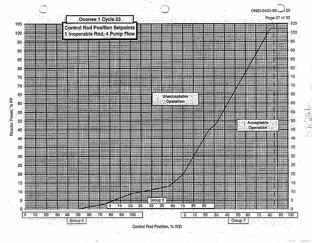
'7..-ONEI.0400-50J 25
I .Page 27 of 33
.:: .:': .. .uo_ -: , Oconeed1 Cycle 23. ' _ I .105
100
95
90
85
80
75
70
65
60
55
50
45
40
35
30
25
20
15
10
5
0
.
:g ControllRod Position Setpolnts. H I 11
8 0qw I It Iiiiiiiiiiiiiiiiiiiiilllllllllllllllllll E 2 S EI lilillllllliiiiii HIM H II [I HH I -H80
Unacceptable -' ill 65l.l E IIHIII I I E ilt IIIII II[lim it illi I 1I I ll IIIlIlI uiiii~illlilt lilil LLL I E E i 2 -7
H l Il [ il 1E1 = H IL
8 55
.,I I Il II 11111|11 11 11111111 1 11 11111111|t1111 [tl ' 11111111 -11i11111111111111111111111X11111 M I' IllE's
. TE t 11111 1 111 1I 11111111111111 111 1 l11111111111 1 111111 24q>8Acceptable- bw>
,.u11'11Ile. ' lllllllllHIMl I l lil t l lllu lllll H. I |t Ilt IIIIIIIIIIIIIIIIIIIIIIIIIIIIIIIE IIIIIIIIIIgI lllllllllllilllkllIlil
g g 1i!1llllllll~illl1lllllilt Illl1 I IlIII~tE~IIIaII~ai!I~il!lII!!l11lll!. . . . . . - 4 5
1 llilt LI. .. 11111111111 1 9 IAli iiiTT~ILII~llsLllfi~IITI~ilIIIIIIImtIiiiiiiiiiiiillllllllllli X m l ll!! l !!ll ALI lil!!l!t!!W4!!!!! 111L! ! ! 1 !!! It11!!!il!ll ......
-115
. . . . . ..1 0ALup 5tU a d'oa l~'.
2 55I5 55 6 5 5 85 9
0 ''10' 20 ^ 30 '-"40 -- 50 -"' 60 70 8 0 90 100IE1 . I , I I I I I I t I . I I I ,1 I-.
I 0 10 : 20 30 40 : 50: 60 70 80 90 100 I| Group 5 |1 ... ... . I
I Group7 Ii:.-Control Rod Position, % WD

I -
105
100
95
90
85
80
75
70
65
60
Oconee .1 Cycle 23
Control Rod Position Setp('1 Inoperable.Rod, 3 Pump
0-
0--1Im -
010
ai)
ONEI-0400-502 25
Page 28 of 33. ; .: - 0 ~105
100
915:.1 ImLL r LIlslliiirooirmrlTil mii . . l.-. . .. I
I LI g lm~llIII II r l l l . .. . . ,
8 0isiai~ii TTTT illlli~l Illlilll ~ I il J IIIllS, 1,,, H II llII lT II , ,,
a~~ ~I i LLmmmwmlmmt II 1 Hll]H I i I i | | | |I iiii i t-u
lilt ~ HI HIM i IL 80II
75
f Unacceptable. lllllllllmlIiiiiilla S 7
60peOpertlon Hl l 4
=._ U. 1111111 6 5
L"L., llt~I II I ILL I r
3~'0
Tlil~liilililiilililiilil4T~I ~lilmilzliii LI IFI 5. IH u 3 05
-I LL I+ Imlr 45-
~5
Iliillilliiliil~liillilliiliillilli > . Acceptble - +mT
!!''!'Ol"!ill32!llli- perat n: C 40
30
TT IIIIIItit~~lll lllllllelllll TllllI[T [T IlllllH m llllll
llllll-llllll Illlllllll~llllilllllL~lllll ':5o
I I m m m LI ILI IL l.. ... IIt ....2TT ~ Illl lrI m ln iml 11 I m T l 1 TTI I ..... I ILI ]II IM I u ll ll ||^wSZL m m T ~ r
0 1L03 4 LILIII 7 80 9LLLL0' li 100fI t I III J rHl ol .. 1Illlllllllllllllmllllllllllllm ll Illllll llii iiiilllllllll
; ~~~~~.. . . ILL /........
|~ 0 10 20 30: 40L 50. 60 70:7, 80 :90 1 00||Group`7 |
.50.
45
40
35
30
25
20
15
10
5
0
Control Rod Position, % WD

ONEI-0400-50 Rev 25Page 29 of 33
Oconee 1 CycIe 23
2.0 Core Operating Limits -- Not Error Adjusted
The data provided on the following pages satisfies a licensing commitment to identify specificparameters before instrumentation uncertainties are incorporated.
References provided in section 1 of this COLR identify the sources for the data which follows.
Core Power Level,
Quadrant Power T
Core OutF
112222
%FP 3C
ilt, %!
Quadrant'Power'Tilt Limits
Referred to by TS 3.2.3
Steady'State' T
0-100 0 -30 30 - 10
5.38. 10.00 9.44
.ransient
D 0 - 30
12.00
Maximum
0- 1 00
20.00
Variable Low RCS'Pressu're-Protective Limits
Referred to byTS 2.1.1
let Pressure -Reactor Coolant Outlet Temperature, °F)sia 3 RCS Pumps 4 RCS Pumps
800 '581.0 578.3900 ' -_590.0 587.3000 598.9 596.3100 607.9 605.2200 616.9 614.2300 " 625.9 623.2

ONEI-0400-50 Rev 25Page 30 of 33
Oconee 1 Cycle 23
Axial Power Imbalance Protective Limits
Referred to by TS 2.1.1
irn00MVUwMIMNMII- � I 0 W -0 MR-9- MIM I 0 W- Cft'%n-- M- M I
%FP .RPS I
4 Pumps
3 Pumps
0O8090100
109.4109.410090800
062.377.081.781.777.062.3
0
* 5.0
-35.0
35.0
35.0
.-35.0,
-14.414.4
35.0
35.0
.,',Operational
-43.4-43.4-39.6-30.0
30.040.339.639.6
-43.4
-43.4
39.6
39.6

ONEI-0400-50 Rev 25Page 31 of 33
Oconee 1 'Cycle 23
Rod In'dex Limits
Referred to by TS 3.2.1
- of~ anR
Operational RI%FP Insertion Limit
4 Pumps
3 Pumps
102100908050155
7750155
260260260
* 260200900
254200900
Shutdown Margin RI Insertion Limit-No iop Rod 1 Inop Rod
220 280
140 23075 -1600 e75
RI WithdrawalLimit
300300300300300300300
300300300300
220140-
-;75:.=0
28023016075

ONEI-0400-50 Rev 25Page 32 of 33
OconeelI Cycle 23
LOCA Limits
ItISU~I MINIMUM 1 la r .. . - . .: NotflnrARMfIitft-lt Ufl01. - . -a - ..
I RA-
Core ElevationFeet '=LOCA LHR kw/ft Limit Versus Burnup
Mk-B11 Fuel0.000
2.5064.2646.0217.7799.53612.00
0 GWd/mtU0 16.6'-17.517.6'17.717.6 0
,17.516.6
0 GWd/mtU15.616.516.817.0'-17.016.715.8
40 GWd/mtU16.617.517.617.717.6 -17.516.6
: 30 GWd/mtU- 15.6
16.516.817.017.016.715.8
62 GWd/mtU12.212.212.212.212.212.212.2
62 GWd/mtU11.611.611.611.611.611.611.6
Mk-B1 0 Fuel0.0002.5064.2646.0217.779-9.53612:00

!,44t ,-1,- i,I . , �� - 1 : 3
ONEI-0400-.50 Rev 25,Page 33 of 33
Oconee I Cycle 23
.. l ~ 4RCPOperation -Loop Average Temp.,T J 3 RCP Operation - Loop Average Temp., TFAod~FjTavg (An~aytical) ~ -- -- I:~Tavg (Analytical)
Z_____<8. <58K1.00.1 <581.0 -<581.0
0.2 <581.1 <581.0.0.3 <581.1 <581.10.4 <581.2 ~<581.10.5 .<581.2- - <581.10.6 <581.2 -<581.1
0.7 -<581.3 .<581.20.8 <581.3 '<581.2,
-0.9 <581.3 -<581.2
1.0 -<581.4 <581.21.1 <581.4 <581.21.2 <581.5 <581.313 <581.5 <581.31.4 - -6<81.5 -. <581.31.5 <581.<5131.6 <581.6 <581.4-1.7 -<581.6 <581.41.8 .- 517<5 81.4.
-1.9 <581.7 <581.4'2.0 <581.8 <581.42.1 <581.8 .<581.5
2.2 <581.8 -<581.5
2.3 <5681.9 <581.524<581.9 <581.5
2.5 -<582.0 <581.62.6 <582.0 <581.6
* 2.7 <582.0 -<581.6
2.8 <582.1 - <81.62.9 <52. - <81.6-3.0 - <82.1 <5 -81.73.1 -. <82.2 -d-<81.7
32 <.582.2 -<581.73.3 - .<82.3 *- <81.73.4 <582.3 -<581.7
3.5 <523 .- <581.83.6 <582.4 <581.83.7 -<582.4 d.<81.8~3.8 -<582.4 81 -
-3.9 <8. -- -<8.
4.0 - 52. - -<81.9
4.1 <5 82.6 <581.9 -
4.2 <526- ~.<81.94.3 <526-<581.94.4 <582.7 -. <582.04.5 -<82.7 - <5 82.0
-4.6 -<87 *-<582.0
4.7 <5.82.8 * <82.048.-<582.8 *-- -<582.1
4. *<82.9 - *<582.1
50<582.9 . <82.1