ocr of mathexpressions - bguben-shahar/teaching/... · · 2011-11-10optical character recognition...
TRANSCRIPT

Ben Gurion University
OCR of Math Expressions
Optical Character Recognition System of
Math Expressions
&
Testing Framework
Yakir Dahan∗
Vitali Sepetnitsky†
Work Report
February 17, 2011
Abstract: In this project we present an application for performing OCR of mathematical ex-pressions, based on segmentation and correspondence �nding, based on correlation coe�cient. Inaddition we present a framework which translates the results into a structural data using cluesregarding the syntax of mathematical expressions. The framework allows to convert the result toa format compatible with Wolfram Alpha computational engine and transfer it to the engine.
∗ Student at Department of Software Engineering, Ben-Gurion University, Beer-Sheba, Israel† Student at Department of Software Engineering, Ben-Gurion University, Beer-Sheba, Israel
1

Contents
I Project Work�ow Description 31 Introduction . . . . . . . . . . . . . . . . . . . . . . . . . . . . . . . . . . . . . . . . 3
1.1 Motivation . . . . . . . . . . . . . . . . . . . . . . . . . . . . . . . . . . . . . 31.2 OCR - De�nition and Applications . . . . . . . . . . . . . . . . . . . . . . . 41.3 OCR evolution � Important dates . . . . . . . . . . . . . . . . . . . . . . . . 41.4 Current state of OCR technology . . . . . . . . . . . . . . . . . . . . . . . . 4
2 Problem Domain and Assumptions . . . . . . . . . . . . . . . . . . . . . . . . . . . 53 Principles of the Algorithm . . . . . . . . . . . . . . . . . . . . . . . . . . . . . . . . 6
3.1 Dividing the image into columns, rows and clumps . . . . . . . . . . . . . . 73.2 Performing OCR of a single character . . . . . . . . . . . . . . . . . . . . . . 9
4 The Final Algorithm we Used . . . . . . . . . . . . . . . . . . . . . . . . . . . . . . 105 The Application (For a complete user-manual see part 2) . . . . . . . . . . . . . . . 11
5.1 The OCR System . . . . . . . . . . . . . . . . . . . . . . . . . . . . . . . . . 115.2 The Visualization & GUI framework . . . . . . . . . . . . . . . . . . . . . . 11
6 Experiments and Results . . . . . . . . . . . . . . . . . . . . . . . . . . . . . . . . . 137 Discussion ans Conclusions . . . . . . . . . . . . . . . . . . . . . . . . . . . . . . . . 178 Future Work . . . . . . . . . . . . . . . . . . . . . . . . . . . . . . . . . . . . . . . . 199 References . . . . . . . . . . . . . . . . . . . . . . . . . . . . . . . . . . . . . . . . . 2010 Useful Links . . . . . . . . . . . . . . . . . . . . . . . . . . . . . . . . . . . . . . . . 20
II User Manual 2110.1 System Requirements . . . . . . . . . . . . . . . . . . . . . . . . . . . . . . . 2110.2 Installation . . . . . . . . . . . . . . . . . . . . . . . . . . . . . . . . . . . . 2110.3 Application Loading . . . . . . . . . . . . . . . . . . . . . . . . . . . . . . . 2110.4 Performing OCR . . . . . . . . . . . . . . . . . . . . . . . . . . . . . . . . . 22
10.4.1 �Image Loading� Tab . . . . . . . . . . . . . . . . . . . . . . . . . . 2210.4.2 �Camera Capture� Tab . . . . . . . . . . . . . . . . . . . . . . . . . 25
2

Part I
Project Work�ow Description
1 Introduction
1.1 Motivation
Have you ever been looking on a printed image of a mathematical expression, or even on an ex-pression you typed using a formula editor (like the one of Microsoft Word), and were interestedto know its de�nition. However, you don't want or don't have the time to perform the exhaustingprocess of copying the expression to a computational engine command line while preserving thecorrect syntax of the expression. Moreover, this process requires you to switch between the engine'swindow and the image which is a very uncomfortable process.
A lot of e�ort, time and maybe nerves :) would be saved if you could take your mobile phone,capture the image and got automatically its analysis performed by some computational engine.
If you agree with us (and you must agree if you ever learned a calculus course :-) ) than yougot into the right place! The motivation of this project is to make the �rst steps towards thewonderful application described above. In this project we take a mathematical expressiongiven as an image, perform an OCR and further analysis process, retrieve the expres-sion from the image and send it to Wolfram Alpha computational engine. The projectcombines a computer vision approach, of performing OCR of single characters and symbols, andsome kind of arti�cial intelligence approach, which is applied after the basic OCR process. At thesecond stage we use syntactic rules of mathematical expressions to repair recognizing errors of theOCR stage, thus trying to reach a syntactically correct expressions and decrease the inaccuraciesof the OCR.
Currently, we perform OCR by using the same approach used to solve the correspondence problemwhen performing stereopsis - by maximizing a correlation similarity measure computed using a setof pre-de�ned templates.
The application we propose here can be usable for:
� People working with mathematical expressions, especially students.
� Finding errors and inconsistencies in a typed mathematical expression.
� Rewriting and redesigning the typed expression.
� Transferring the expression between di�erent applications and text �les.
3

1.2 OCR - De�nition and Applications
OCR is an abbreviation for O ptical C haracter R ecognition. OCR allows a machine to recognizecharacters through an optical mechanism. The naming OCR refers to all technologies whichperform translation of scanned/captured images of text (which can be handwritten or typewritten)to a standard, machine-encoded text with the same interpretation. The purpose of an OCRsystem is to classify optical patterns, contained in the image, to corresponding alphanumeric orother characters. After performing OCR, a further processing can be applied to the text, suchas text-to-speech and text mining. OCR is a �eld of research in computer vision and arti�cialintelligence.
1.3 OCR evolution � Important dates
1929 A �rst patent on OCR was �rst obtained in Germany by Gustav Tauschek, for a mechanicaldevice which performed OCR using a photodetector and templates.
1950 The �rst commercial OCR application was invented in USA, by David H. Shepard, a crypt-analyst at the Armed Forces Security Agency. A corporation was founded and namedI ntelligent M achines R esearch (IMR). It delivered machines which converted printed textswhich were especially credit card numbers and teletype typewritten messages, to a computertext.
1973 The �rst development of an omni-font OCR system � A computer program which wascapable of recognizing text printed in any normal font. This program was intended to theblind people in order to have the computer read text to them loudly.
1992-1996 The Information Science Research Institute (ISRI) conducted the Annual Test of OCRAccuracy in order to encourage the development of OCR systems for understanding machineprinted documents.
1.4 Current state of OCR technology
Today, there exist a lot of commercial applications for recognition of Latin script. According toa study based on recognition of 19th and early 20th century newspaper pages concluded thatcharacter-by-character OCR accuracy for commercial OCR software vary from 71% to 98%. Otherareas in OCR - including recognition of hand printing, cursive handwriting, and printed text inscripts other than Latin �are still a subject of active research.
4

2 Problem Domain and Assumptions
In order to de�ne the problem formally we decided about an initial set of characters and mathe-matical symbols that our application should recognize:1
1. Capital English letters (′A′, . . . , ′Z ′) and small English letters (′a′, . . . , ′z′).
2. Small Latin letters which are usually used in mathematical expressions: ′α′, ′β′, ′γ′, ′δ′, ′ε′,′θ′, ′λ′, ′π′ and ′σ′.
3. Digits (′0′, . . . , ′9′).
4. Binary operators: ′+′, ′−′, , ′∗′, ′÷′ and ′/′.
5. Boolean operators: ′ <′ and ′ >′.
6. Parentheses signs: left parenthesis (′(′) and right parenthesis (′)′).
7. The root character (′√′).
8. The equals (′ =′) character.
9. Sum (′∑′) and product (′
∏′) symbols.10. Integral (′
´ ′) and derivative (′′′) symbols.
11. The in�nity symbol (′∞′).
As it was said above, the goal of this project was to combine computer vision approach whichallow us to perform OCR of single symbols. Furthermore we wanted to use syntactic rules of math-ematical expressions to repair errors of the OCR stage and construct correct expressions from theread characters, thus leading us to application based on some kind of arti�cial intelligence.
We assume that the images given to the application, contains only characters from the set givenabove, which are syntactically correct. For example, the following expressions aren't acceptable:
+6, e− andk∑. The second assumption is useful especially for the operation of retrieving the
mathematical expression from the read characters.
In addition, we assume that the intensity of the characters seen on the image is clearly di�er-ent from the intensity of the background. As it can be seen from the next section, our algorithmcan deal with noisy images, but it is limited to images in which the characters can easily beextracted from the background.
5

3 Principles of the Algorithm
Our approach for solving the problem was divided to 4 stages:
1. First, we perform a simple image processing of the image using the following operations:
(�a) Converting the image to gray scale by eliminating the hue and saturation informationwhile retaining the intensity. We remind here that by assumption the intensity ofthe expression's characters on the image should be strictly lower than the intensity ofthe background and therefore, converting to the image to gray scale, shouldn't changedrastically the number of expression's pixels.
(�b) Converting the gray-scaled image to black&white, by using Otsu's method. Since weassume that the initial image consists of a background and the mathematical expressiononly, we should get a white background with characters and mathematical symbols lyingon it.
(�c) Removing all connected groups of pixels with less than 9 pixels - made in order to reducenoises (but may cause problems in handling small fonts).
(�d) Cropping the result image to be of size of the minimal bounding rectangle - for retainingthe expression only and omitting the background.
2. Next, we has to divide the given expression into single characters with a true order. Thisproblem is solved easily by thinking about the way we read a mathematical expression,constructed from the symbols given above. Usually the expression is read with left-to-rightand top-to-bottom order. Fortunately, the number of exceptional expressions is limited(according to the set of symbols given above) and refers only to the second rule:
(�a) The expression10∑k=1
x is read as �sum (x, k = 1 to 10)�. Similarly, the expression10∏k=1
x is
read as �product (x, k = 1 to 10)�. In other words, these expressions are read left-to-rightbut bottom-to-top (regarding the k = 1 and 10).
(�b) The expression
∞̂
−∞
x2 is read as �integral from −∞ to∞ of x2. Here, again, the expres-
sion is read left-to-right but bottom-to-top.
For the reasons stated here, we assumed that OCR can be performed on the expression'scharacters in the left-to-right and top-to-bottom order. The process of inverting the orderof characters in the special cases, is done during the construction of the full expression fromthe single characters read by the OCR process.
The division of the image into single characters and symbols was done as described at section3.1.
3. For each character/symbol we got from the division described above, we has to performand OCR and return an interpretation of this character. The interpretation was done bymaximizing a similarity measure as described at section 3.2. In order to perform the processof �nding the most corresponding interpretation of the image, we �rst re-size it to a standardsize which is the size of all the templates supplied (for details see section 3.2) which is 42rows X 24 columns.
6

4. We called the result of the above stages a �pseudo-result� , since, it isn't the �nal result ofthe algorithm - the �nal result is retrieved after performing a conversion of the pseudo-resultto a mathematical expression, using syntactic clues of expressions of this type.
3.1 Dividing the image into columns, rows and clumps
Given a binary (black&white) image, let's de�ne some de�nitions:
A valid column is a column whose height equals to the height of the image and width is at least1. In addition, all its vertical, unit width, columns, have at least one black pixel.
A maximal valid column is a valid column of maximal size. Meaning, that if another unit-pixels column of the image is added to this valid column (on left or right), it becomes invalid(the new column doesn't contain any black pixels).
A valid row is a row of pixels whose height is at least 1. In addition, all its horizontal, unitwidth, rows, have at least one black pixel.
A maximal valid row is a valid row of maximal size. Meaning, that if another unit-pixels rowof the image is added to this valid row (on top or bottom), it becomes invalid (the new rowdoesn't contain any black pixels).
A connected component is a set of pixels, in which any pixel has a neighbor from the set inone of the 8 directions (N, NW, W, SW, S, SE, E, NE).
A clump is a connected component of maximal size. Any pixel, external to the clump, will breakthe connectivity requirement if added to the clump. Dividing the a black&white image intoclumps is the simplest kind of segmentation.
When carefully thinking about a given (black&white) image representing a mathematical expres-sions, if we want to divide it into single symbols, while preserving the order of symbols in theexpression, we can use the following way:
Algorithm 1 Division of the image to single symbols
1. Divide the image into a set, C, of maximal valid columns.
2. For each column c ∈ C:
(�a) Divide c into a set, R, of maximal valid rows (c is treated as a standalone image) .
(�b) For each valid row r ∈ R:
i. Divide r into a set of clumps, S - each clump s ∈ S is assumed to be a single symbol.
7

In order to demonstrate the above algorithm, we present its operation on the mathematical ex-pression given below:
Figure 1: The mathematical expression on which Algorithm 1 is applied
After computing the maximal valid columns, we obtain the following set C of columns (the columnsare highlighted):
Figure 2: Retrieving columns from the image
Here, we present the maximal valid lines of the two central columns from C:
Figure 3: Retrieving lines from two central columns
As it can clearly bee seen, the left column consists of 3 rows and the right column consists of a2 rows. Now, we divide each row into clumps, which are numbered according to 〈m, n〉 patternwhere m is the number of the row (from top to bottom) and n is the number of the clump (left toright, top to bottom). Here is the result we should get:
8

Figure 4: Dividing the retrieved lines into clumps
3.2 Performing OCR of a single character
One of the main parts of this project is taking an image, representing a single character or mathe-matical symbol, and giving it the interpretation of this character/symbol. We decided to implementour OCR system by using an intensity based method by establishing correspondence of the imageto a pre-saved set of characters with known interpretations. The measure of similarity we chose tomaximize is a 2-D correlation which is described below:Given two matrices A and B of the same size, the 2-D correlation coe�cient r is calculated by thefollowing way (A and B represent the mean values of A and BL accordingly):
r =
∑m
∑n
(Amn − A
) (Bmn −B
)√√√√√√
∑m
∑n
(Amn − A
)2∑
m
∑n
(Bmn −B
)2The correlation coe�cient ranges from =1 to 1. A value of 1 implies that a linear equation describesperfectly the relationship between A and B, with all data points lying on a line for which Bmn
increases as Amn increases. A value of =1 implies that all data points lie on a line for which Bmn
decreases as Amn increases. A value of 0 implies that there is no linear correlation between thevariables. We can see that the expression
(Amn − A
) (Bmn −B
)is positive if and only if Amn and
Bmn lie on the same side of their respective means. Thus the correlation coe�cient is positive ifAmn and Bmn tend to be simultaneously greater than, or simultaneously less than, their respectivemeans.In our case, the two matrices are:
1. A is the image on which OCR should be performed.
2. B is the template image, which represents a character or a mathematical symbol whoseinterpretation is known.
Moreover, in our case A andB are binary matrices, since we convert the input image to black&whiteand the templates are stored as black&white. Therefore, high value of a correlation coe�cientmeans that there are a lot of pixels, lying at the same places in A and B, with same values andtherefore A can get the interpretation of B (which is known).
In order to use this method, a set of template images should be pre-saved. These templatesserve as B matrices when computing the correlation coe�cient. For this purpose, we created a setof templates which is supported with our application and can be found in the templates folder.
9

4 The Final Algorithm we Used
Given an image I, assumed to be an image of a mathematical expression:
Algorithm 2 The whole algorithm
1. Compute: GrayScaleI ← image to gray scale (I)
2. Compute: Black&WhiteI ← image to black andwhite (GrayScaleI)
3. Initialize: pseudo_result← Ø
4. Divide Black&WhiteI into a set of columns, C, according to the method speci�ed in section3.1.
5. For each column c ∈ C do:
(�a) Divide c into a set of lines, L, according to the method speci�ed in section 3.1.
(�b) For each line l ∈ L do:
i. Divide l into a set of clumps, S, according to the method speci�ed in section 3.1.
ii. For each clump, s ∈ S, assumed to be a single character (or a part of a singlecharacter):
�A. Perform character recognition using the statistical method described above andobtain a character c.
�B. Analyze c for being start or end of a power:
�C. In case c is a start of a power:pseudo_result← pseudo_result ∪ ∧(c.
�D. Else, in case c is an end of a power or a square root:pseudo_result← pseudo_result ∪ c).
�E. Else - c is a regular symbol:pseudo_result← pseudo_result ∪ c.
6. Compute the �nal mathematical expression from the pseudo-result, using statistical clues ofmathematical expressions:return ComputeF inalResult(pseudo_result).
10

5 The Application (For a complete user-manual see part 2)
For the purpose of demonstrating our OCR system capabilities we have created an applicationwhich serves in addition as a testing environment to our OCR implementation and its furtherimprovements. Our application consists of two parts: The OCR system and The GUI frame-work:
5.1 The OCR System
The �rst part of the system, which performs the OCR of the expression by using the �rst 3-stagesof the algorithm described above, was implemented in MATLAB. The implementation is dividedinto the following scripts:
1. The main �le OCR.m: This �le contains one main function named OCR(), which performsthe OCR of an image stored in the current folder of MATLAB, by using the auxiliary func-tions described below. The pseudo-result of the OCR is written to a �le and is used by thesecond part of the implementation (see below) in order to �nalize the expression which wasrecognized.In order to change the name of the image on which the OCR is performed, the name writtenin line 11 of the script, can be replaced with the desired name. In addition, the name of the�le, into which the pseudo-result is written, can be changed at line 12 of the script.Note: Because of the way we implemented the testing framework - neither the name of theimage-�le, nor the name of the output text-�le, should be changed in order to perform OCRon di�erent images. For further information see the explanation for the second part of theimplementation.
2. The functions columns() and lines() which are stored accordingly in the �les columns.mand lines.m. are intended to divide the image, on which the OCR is performed, to columnsand lines accordingly, as described in section 3.1.
3. The function create_templates(), which is stored in the �le create_templates.m, creates adataset of templates from the templates of characters stored in the symbols folder. Thisdataset is used later for performing OCR by the read_letter() function (see below).
4. The �le read_letter.m contains the function read_letter() which is the function that prac-tically performs OCR of a given character and returns the resulting character. This function�nds the correspondence by maximizing the correlation coe�cient, calculated on each of thetemplates of the templates dataset, as described in section 3.2.
5.2 The Visualization & GUI framework
This part of the implementation includes the implementation of the 4th stage of the algorithm. Itis responsible of taking the pseudo-result returned by MATLAB, and performing its �nalizationand conversion to a valid mathematical expression which is then sent to Wolfram Alpha compu-tational engine by opening it in a Mozilla Firefox browser.
In order to make our OCR system standalone and more convenient to the user (while gettingcloser to the application goals described above) we have implemented a GUI based system inJava, using the Swing GUI toolkit. In order to allow our application capture images from aweb-camera, we have used the JMF (J ava M edia F ramework) library that enables audio, video
11

and other time-based media to be added to Java applications.
Furthermore, in order to allow our application to connect with MATLAB computation engine,we used an open source Java RMI-based tool called JAMAL (J ava M atlab L inking), whichmade it possible to call the MATLAB functions performing OCR - from the Java application,without requiring the user to actually open MATLAB.
Here we present a block diagram describing our application:
Figure 5: Block Diagram of the Algorithm
12
6 Experiments and Results
In order to test the proposed algorithm we had to de�ne a common measure of accuracy rate. Theaccuracy rates of these kinds of algorithms can be measured in several ways, and how they are mea-sured can greatly a�ect the reported accuracy rate. For example, if the structure of mathematicalexpressions (the context) is not used to correct the resulting expression, a character error rate of5% (95% accuracy) may result in an error rate of 9% (91% accuracy) or worse if the measurementis based on whether each composed expression was recognized with no incorrect letters.
We decided to measure the accuracy of the recognized expression returned after the both parts ofthe algorithm - the OCR recognizer and the �nal converter. There can be two types of mistakesin the recognized expressions:
1. Replacing characters with wrong characters - the number of these mistakes was denoted asα and they got a weight of 1.
2. Placing true characters in wrong places - the number of these characters was denoted as βand they got a weight of 0.5 (less than the �rst type).
The measuring of the accuracy rate was done using the formula: 1− 100 · (α+0.5β)γ
. In this formulaγ represents the total number of characters and symbols in the input formula.
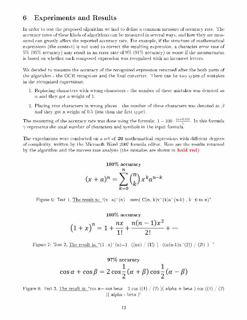
The experiments were conducted on a set of 20 mathematical expressions with di�erent degreesof complexity, written by the Microsoft Word 2007 formula editor. Here are the results returnedby the algorithm and the success rate analysis (the mistakes are shown in bold red):
100% accuracy
Figure 6: Test 1, The result is: �(x+a)^(n)= sum( C(n, k)x^(k)a^(n-k) , k=0 to n)�
100% accuracy
Figure 7: Test 2, The result is: �(1+x)^(n)=1+((nx) / (1!) )+((n(n-1)x^(2)) / (2!) )+�
97% accuracy
Figure 8: Test 3, The result is: �cos a+ cos beta =2 cos ((1) / (2) )( alpha + beta ) cos ((1) / (2))( alpha - beta )�
13

94% accuracy
Figure 9: Test 4, The result is: �x=((-b+ sqrt(b^(2)-4aC)) / (2a) )�
100% accuracy
Figure 10: Test 5, The result is: �A=P(1+((r) / (n) ))^(nt)�
93% accuracy
Figure 11: Test 6, The result is:�integrate(e^(-x2) , - in�nity, in�nity)=( integrate(e^(-x2) , - in�nity, in�nity)* integrate(e^(-y2)
, - in�nity, in�nity))^(1/2)= sqrt( pi )�
96% accuracy
Figure 12: Test 7, The result is: �((1) / (2 pi ) )2 pi L0((d theta ) / (a+b sin theta ) )=((1) /(!!a^(2)-b^(2) ))�
87% accuracy
Figure 13: Test 8, The result is: �a(b+C)=ab+aC�
14

94% accuracy
Figure 14: Test 9, The result is: �((a) / (b) )+((C) / (d) )=((ad+bc) / (bd) )�
86% accuracy
Figure 15: Test 10, The result is: �y!/7a^(2)+b^(2)+tal7(b)=((y(a+b)) / (Laa(b)) )�
90% accuracy
Figure 16: Test 11, The result is: �(ax+b)(Cx+d)=aCx^(2)+(ad+Cb)x+bd�
100% accuracy
Figure 17: Test 12, The result is: �(((a) / (b) ))^(n)=((a^(n)) / (b^(n) ))�
100% accuracy
Figure 18: Test 13, The result is: �f(a)=((1) / (2 pi i) )* integrate(((f(z)) / (z-a) ))�
100% accuracy
Figure 19: Test 14, The result is: �tan theta =(( sin theta ) / ( cos theta ) )�
15

80% accuracy
Figure 20: Test 15, The result is: �Laa(a)+taa(b)=((sill(a+b)) / (cOs(a)cOs(b)) )�
96% accuracy
Figure 21: Test 16, The result is: �f(z)= sum(((f^((n))(a)) / (n^(1) )(z-a)n) , n=0 to in�nity)�
89% accuracy
Figure 22: Test 17, The result is: �f(x)=((1) / (!!x+1) )+!/7x^(2)+3�
100% accuracy
Figure 23: Test 18, The result is: �cos n theta +i sin n theta =( cos theta +i sin theta)^(n)=e^(in theta )�
100% accuracy
Figure 24: Test 19, The result is: �2(4s^(-2)-7b)^(1 / x)+ ln (2b)'- cos '5d*((df(x)) / (dx) )=((d)/ (dx) )g(x)�
100% accuracy
Figure 25: Test 20, The result is: �f(x)=a0+ sum((a cos ((n pi x) / (L) ))+b sin ((n pi x) / (L) ),n=1 to in�nity)�
16

7 Discussion ans Conclusions
In this project we tried to create a reliable and applicable implementation of an algorithm forperforming OCR on mathematical expressions. The total accuracy of the algorithm, accordingto the experiments we conducted, is close to 95% for typed images. These recognition rate isquite surprising since we have used a very simple method for performing OCR of a single charac-ter/symbol.
One of the disadvantages of our system is that it requires calibration to read a speci�c font.The current version of the application works well on characters written in fonts similar to the oneof the templates. However, we created the templates dataset using the font of the formula editorsupplied by Microsoft O�ce programs, which is a very common formula editor and therefore theusability of our application is still very high.
One of the limitations of our algorithm is a very high sensitivity to rotation of the expressionappearing in the image (its orientation) - the mathematical expression should be placed horizon-tally or very close to horizontally. In the table below we can see the result of the algorithm onrotated images and it is clearly seen that the total accuracy decreases drastically as the expressionis rotated from 0◦.
Image Obtained result Accuracy rate
(x+a)^(n)= sum( C(n,k)x^(k)a^(n-k) , k=0 to n)
100%
(x+a)^(n)= sum( C(n,k)x^(k)a^(n-k) , k=0 to n)
100%
(x+a)^(n).+ sum( C(k,n)x^(k)a^(n1k) , k!!0 to h)
82%
cx+a)^(h)!! sum(ckn, k=0 ton)x^(k)a^(n!k
60%
Figure 26: The results of the algorithm on an image with di�erent rotations
17

Another disadvantage of our method is characters and mathematical symbols which looks verysimilar and therefore the correspondence coe�cients of images on one of them are very close. Asexamples we can give the following pairs of characters:
1. The little-o character (′o′) is very similar to the zero character (′0′) and to the big-o character(′O′).
2. The little-h character (′h′) is very similar to the little (′n′) character - can be seen at the lastrow of the table.
These similarities can cause mistakes in which an image representing a symbol, can get an interpre-tation of other (similar) symbol. Sometimes, that kind of mistakes can be repaired by our secondpart of the implementation. For example, we know to repair the mistake in which the string ′cos′
is interpreted as ′c0s′ (the character ′o′ is replaced by the character ′0′).
While testing the application on images captured by a web-camera, we noticed another disad-vantage of the algorithm; Our algorithm is very sensitive to little errors, generally caused byinsu�cient quality of captured images. For example, the image below is treated as (1 +xr)n since,if we look close on the x character, we can see it has a little defect on its top left side which isrecognized as another clump (marked with a red circle):
Figure 27: Captured image with a defect
18

8 Future Work
The application presented here can be considered as a prototype of more extensive and complicatedapplication which has more capabilities. Here we propose improvements and additional featureswhich can be applied to the current version of the application in order to improve it:
� First of all, the process of performing OCR to a single character can be improved. As itwas stated before, the current application is limited to a font used by the formula editor ofMicrosoft Word or similar fonts. An important improve is to add more templates of anotherfonts or even change the OCR method of a single character and use a more sophisticatedmethod, capable to deal with any font.
� A recursive process can be implemented in order to deal with clumps; currently the appli-cation can't deal with a composite expressions located in a single line, like the expressionbelow. In next version a recursive handling of clumps can be implemented - allowing to startthe process of �nding columns, lines and clumps again, after treating the �rst clump of theline. This will allow the algorithm to treat expressions of the above type.
Figure 28: An expression which is badly treated by the current versionof the algorithm and can be treated better in next implementations
� A method for treating the rotation of the given expression can be proposed - in order tominimize the damage of the �nal result, caused by rotation issues.
� A more complicated noise reduction can be implemented, allowing the application to treatnoisy images captured from camera. The implementation of a better noise reduction method,may allow the application to be installed on a mobile device with a camera, thus extendingits capabilities.
19

9 References
Here we list the sources of information which were used while working on the project and writingthis document:
1. The Association for Automatic Identi�cation and Data Capture Technologies (AIM) (2000),�Optical Character Recognition (OCR)�.Online version is available here.
2. Øivind Due Trier, Anil K. Jain and Tor�nn Taxt, �Feature extraction methods for characterrecognition-A survey�, Elsevier Science B.V., 1996.Online version is available here.
3. Vishvjit S. Nalwa. (1993). Stereo, correspondence establishment. �A Guided Tour of Com-puter Vision�. Addison-Wesley. p226-227.Online version is available here.
4. Ben Shahar, Ohad, �3D Shape and Depth Inference IV - Stereopsis�, Lecture notes from�Introduction to Computational and Biological Vision� course, 2011.Online version is available here.
5. Wikipedia, A free web encyclopedia, http://en.wikipedia.org/wiki/Main_Page.
10 Useful Links
Here you can �nd references to websites containing tutorials to the technologies and tools used tocreate the application:
1. Mathworks o�cial website:http://www.mathworks.com/products/matlab/.
2. JAMAL o�cial website:http://jamal.sourceforge.net.
3. SUN tutorials to Java Swing toolkit: Creating a GUI With JFC/Swing:http://download.oracle.com/javase/tutorial/uiswing/.
4. Wolfram Alpha computational engine:http://www.wolframalpha.com/.
5. �Introduction to Computational and Biological Vision�: course homepage:http://www.cs.bgu.ac.il/~ben-shahar/Teaching/Computational-Vision.
20

Part II
User Manual
10.1 System Requirements
� Our application was tested on a 32 bit machine with a Windows XP operating system. Sinceit is written in MATLAB and Java, there should not be a problem to install it on anothertype of machine with other kind of operating system, but we can't guarantee an installationsuccess.
� The machine should have MATLAB and Mozilla Firefox browser installed and in addition itshould have Java 1.6 or higher.
� Since the application reads and writes �les from and to the installation directory, you shouldhave the permissions to perform this operations. In addition, you should have a permissionto edit the directory where MATLAB is installed and the MATLAB classpath, this is orderto install the JAMAL server and client.
10.2 Installation
The whole application consists of a single .jar �le which is ran by simply double clicking on it.The directory which contains the application .jar �le should contain also the OCR.m, columns.m,lines.m, create_templates.m and read_letter.m scripts.
Before running the application you should install the JAMAL .jar �le, please follow the followinginstructions:
1. Copy the supplied jar �le named �jamal− 2.1.jar� to the �/java/jar� sub-folder located inthe MATLAB folder.
2. Get into MATLAB.
3. Type in the MATLAB prompt: �edit classpath.txt�.
4. In the opened �le, add the line. �$matlabroot/java/jar/jamal − 2.1.jar�.
5. Save the �le and exit.
10.3 Application Loading
When opening our application, it �rst connects to the MATLAB computational engine by runninga server on MATLAB and a client on our application. This process can take several seconds duringwhich the �Loading Please Wait!� message is presented on the screen. After that process and incase of a successful operation, the main screen of the application is shown.
21

Figure 29: Loading screen of our application
Notes:
1. During the connection process, you can cancel and exit by pressing the �Close� button shownbelow the loading animation. In this case, the application unloads securely in order to allowthe MATLAB stay in a stable state. This process can take several seconds - please be patient!
2. Sometimes the connection to MATLAB fails at �rst run and in this case our applicationens. The fault may be caused by connection timeout or licensing errors. In case you have aright licensed version of MATLAB, which operates correctly while it is ran as a standaloneapplication, please try to run our application again.
10.4 Performing OCR
Our application provides two ways for uploading images and performing OCR. These ways areshown on the tabs of the application main screen and are loading image from a pre-saved �le (the�rst tab - �Image Loading�) and capturing an image from a web-camera connected to the machineon which the application is installed (the second tab - �Camera Capture�).
Figure 30: The two ways of image loading provided by the application
10.4.1 �Image Loading� Tab
As it was said above, this tab allows the user to load a pre-saved image �le which represents amathematical expression on which OCR should be performed. The loading is done by pressingthe �Browse� button, choosing an image and pressing �Open�. Currently, the supported formatsof images are �.GIF�, �.PNG�, �.JPG� and �.BMP�. After pressing �Open� the image is loaded andshown on the application screen.
22

Figure 31: The image loading screen with a loaded image
After an image was loaded you can change it by pressing the �Browse� button again and choosingother image. In addition you can delete the image from the view by pressing the �Clear� button.In this case the image will be removed from the application screen and you will return to the mainscreen shown in �gure 32.If you want to crop the image horizontally you can use the mouse in order to change its top andthe bottom boundaries. Pressing the �Uncrop� button cancels the last cropping. The crop featureis helpful when you have an image which contains several lines of mathematical expression. Thecropping is necessary in this case, in order to focus the OCR system on a single expression. Hereis a screenshot of a cropping made to an image:
Figure 32: Cropping an image
Now, after an image representing an mathematical expression has been loaded, OCR can be per-formed by pressing the �OCR� button. The OCR process can take several seconds, depends on thecomplexity of the given expression. During that process, all the buttons are made not-accessibleand you can't exit the application (in order to keep MATLAB in a stable state).
23

Figure 33: The application view while performing OCR
After a successful OCR has been performed, the application window spreads out and its right partshows the result of the OCR. You can see the result in the text-box at the top of the right side.For convenience we allow the option to wrap the result (useful when it is wider than the window)or to see it not wrapped - as a single line. The option is �wrap� by default. You can change thewrap state by checking/un-checking the check-box �wrap ocr answer� below the OCR result.In addition, the result window provides the option to clear the OCR result and make the appli-cation window look like in Figure 33. This can be done by pressing the �Clear OCR� button. Incase you press the �Clear� button now, the OCR result will be cleared too and hidden.
Note: The OCR result shown in the text-box is after performing further processing of the pseudo-result returned by MATLAB. While transferring the result to Wolfram Alpha computational en-gine, additional processing is made in order to make the result conform to Wolfram Alpha querystructure.
Figure 34: The result window after performing OCR
The result of the OCR is automatically delivered to to Wolfram Alpha. Thus, immediately afterreturning from the call to OCR, a new �refox browser window is opened and the result is shown,after processing by Wolfram Alpha. In case you closed the browser window with the result of theOCR and you want to see it again, you can press the �Load to Wolfram� button and the browserwindow will be loaded again.
24

Figure 35: The result after performing OCR, delivered to Wolfram Alpha
10.4.2 �Camera Capture� Tab
In addition to performing OCR on pre-saved images, we provide the option to capture images on-the-�y, by using a web-camera. This feature is implemented in the application and can be reachedby pressing the �Camera Capture� tab. In case the camera is connected and initialized properly,the application detects it and presents a window similar to image loading window shown at �gure33. Below the window which shows the image currently viewed by the camera, you can see the�Capture� button, which allows to capture the currently shown image and perform an OCR on it.The image is shown with a horizontal and vertical grid-lines in order to help you capturing themathematical expression with a horizontal orientation. As it was shown in the conclusion part,the rotation of the image is critical to the algorithm success.
Figure 36: The camera capturing screen with math expression in front of camera
After pressing on �Capture� the application window spreads out and its right part shows thecaptured image. Here, again you can perform cropping of the image using the mouse and cleanthe crop result by pressing �Uncrop�. In addition, you can save the captured image by pressing
25

the �Save as� button. Currently only saving to �.JPG� format is allowed. Note that the savingoperation is optional and it isn't required in order to perform an OCR on the captured image.Also, please note that the image that will be saved is the cropped version of the captured image (incase a cropping was done). Like in the �Image Loading� mode, you can clear the captured imageby pressing the �Clear� button.
Figure 37: The camera capturing screen after capturing an image
In order to perform OCR press the �OCR� button on the �captured image� side. The process ofperforming OCR is similar to the one described above (in the �Image Loading� mode). After asuccessful OCR has been performed, the application window spreads out again and its most rightpart shows the result of the OCR. You can see the result in the text-box at the top of the rightside, clear the OCR result by pressing on the �Clear� button and load the result to Wolfram Alphaby pressing �Load to Wolfram�.
Figure 38: The camera capturing screen after performing OCR on a captured image
26

Notes:
1. If you press on the �Clear� button in the middle window, the captured image and the OCRresult will be removed from the screen.
2. Pressing the �Capture� button again will capture the image currently shown in the leftmostscreen and the currently captured image will not be saved (except if you saved it before).The previous OCR result will disappear too.
3. In case of a failure with the connection to the camera, the screens of the �Camera Capture�mode disappear and a �Connect to camera� button is shown. After resolving the connectionproblem, press the button and the screen with the camera output will be shown again.
Figure 39: The screen of �Camera Capture� mode in case of a camera connection failure
27