octaflowii manual docx - ala scientific · safety information ... troubleshooting ... is under...
TRANSCRIPT

OCTAFLOW II
ALA Scientific Instruments Inc.
E-mail: [email protected]
OCTAFLOW II™
Manual
Ver. August 2010
ALA Scientific Instruments Inc. 60 Marine Street
Farmingdale, NY 11735 Tel. # 631.393.6401
FAX: # 631.393.6407 mail: [email protected]
www.alascience.com

Table of Contents: Page # GLOSSARY .......................................... .......................................................................... 4
SAFETY INFORMATION ................................ ................................................................ 5
OCTAFLOW II II™ SYSTEM CHECKLIST .................. ................................................... 6
OCTAFLOW II™ COMPONENTS ........................... ....................................................... 7
USB Interface .............................................................................................................. 7
Valve Manifold ............................................................................................................ 7
The Micromanifold® ..................................................................................................... 8
Teflon Tubing .............................................................................................................. 8
Compression Fittings .................................................................................................. 8
Lee Co. LFAA Solenoid Valve ..................................................................................... 9
Pinch Valve ................................................................................................................. 9
Solution Reservoir ....................................................................................................... 9
Alt. Valve or Flush Valve ........................................................................................... 10
Magnetic Stand ......................................................................................................... 10
USB Cable ................................................................................................................ 10
PVCTubing ................................................................................................................ 10
OCTAFLOW II™ Software ........................................................................................ 10
INITIAL SETUP ..................................... ........................................................................ 11
Parts Check List ........................................................................................................ 11
System Assembly Setup ........................................................................................... 11
Electrical Noise ......................................................................................................... 13
Using the OCTAFLOW II™ ....................................................................................... 14
DAILY USAGE ....................................... ....................................................................... 16
Getting the OCTAFLOW II™ ready for an experiment .............................................. 16
Filling the Reservoirs ................................................................................................. 16
Priming the System ................................................................................................... 16
Rear Panel of the Interface ....................................................................................... 18
Some theory to keep in mind when using the OCTAFLOW II™ ................................ 19
The De-Gassing Feature of the OCTAFLOW II™ ..................................................... 19
Dead Volume ............................................................................................................ 20
IMPORTANT OCTAFLOW II™ FEATURES ................... ............................................. 21
Variable Valve Voltages ............................................................................................ 21
The Pressure System ................................................................................................ 21
TTL I/O ...................................................................................................................... 21
Analog Out ................................................................................................................ 21
SOFTWARE SETUP & CONFIGURATION .................... .............................................. 22
Software Installation/upgrade .................................................................................... 22
Firmware Software Installation .................................................................................. 22
TROUBLESHOOTING ................................... ............................................................... 23
Fixing a Leaky Valve ................................................................................................. 23
Removing Bubbles from the OCTAFLOW II™ System ............................................. 24
SPEED OF EXCHANGE (EXCHANGE TIME FOR FLUIDS) ...... ................................. 25
OCTAFLOW II™ Output ........................................................................................... 25

EXPERIMENTAL CONFIGURATIONS ....................... .................................................. 26
CLEANING AND MAINTENANCE .......................... ..................................................... 27
Daily Cleaning of Reservoirs and Valves .................................................................. 27
LIMITED WARRANTY .................................. ................................................................ 28
SAFETY NOTICE.......................................................................................................... 29
DIAGRAMS SECTION .................................. ................................................................ 30
Style 1- Setup for Gravity Fed Wash from Large Reservoir ...................................... 30
Style 2 - Setup for Suction Flush in Micromanifold .................................................... 30
Style 3 - Setup for Wash Reservoir & Suction via. 2-way Valve ................................ 31
Figure A. - Installation of the Tip on the Micromanifold ............................................. 32
Figure B. - Installation of the Tip on the Micromanifold ............................................. 33
Figure C. - Valve Manifold Maintenance & Service ................................................... 34
Figure D. - Syringe and Plug Assembly .................................................................... 35
Figure E. - Compression Fittings for Teflon, PE Tubing ............................................ 36
Figure F. - Filling the Reservoirs ............................................................................... 36
Figure G. - OCTAFLOW II™ System with Pinch Valves ........................................... 37
Figure H. - OCTAFLOW II™ Rear Panel .................................................................. 38
Figure I. - Alternate Position of Flush Tube ............................................................... 38
Figure J. - Hook-Up of Suction/Flush/Flush Valve .................................................... 39
Figure K. - Example of Cell Preparation Using OCTAFLOW II™ .............................. 40
Figure L. - Using the Flush Valve as a Continuous Wash ......................................... 41
Figure M. - The J-Tube Method ................................................................................ 42
Figure N. - U-Tube for the OCTAFLOW II™ ............................................................. 42
Figure O. - OCTAFLOW II™ Output with 100 µm Tip ............................................... 43
SOLENOID VALVE MAINTENANCE ........................ ................................................... 44
Cleaning and Maintenance of LFAA Valves .............................................................. 44
Diagnosing the Problem ............................................................................................ 44
2-WAY SOLENOID VALVE CLEANING ..................... ................................................. 45
3-WAY SOLENOID VALVE CLEANING ..................... ................................................. 46
Cleaning of Normally Closed Side of Valve ............................................................... 46
Cleaning of Normally Open Side of Valve ................................................................. 47
Recommended Cleaning Solutions for Lee Co. Solenoid Valves .............................. 48
SOLENOID VALVE LIMITED WARRANTY ................... .............................................. 49
IMPORTANT NOTE: BEFORE BEGINNING ANY WORK WITH YOUR OCTAFLOW II™, PLEASE READ THE SAFETY INFORMATION AND WARRANTY PAGES; THESE CONTAIN VITAL INFORMATION THAT THE USER MUST KNOW!

Glossary Air Manifold The series of tubes that port air/gas pressure to all the reservoirs. Barb Specifies the part of a connector that is supposed to be inserted into a
tube. Barbed Fitting A fitting with a barb on at least one end. CFG Configuration File. COM Common port of a valve. Having access to both NO port and NC port in a
three-way valve. Compression Fitting
Used to connect small bore tubing with valve.
Configuration File
Spreadsheet style listing of each reservoir number, name, valve voltage, and pressure.
Configuration Page
1st menu item of OCTAFLOW II™ software where flush time and valve high-voltage on time is recorded.
OCTAFLOW II™
Drug Application Device
De-gas To remove a gas from a liquid. Dead Volume An amount of liquid that is unstirred in a system. (Usual definition). Dead Volume The amount of liquid A that must pass before liquid B arrives. (Definition
used with Micromanifold of OCTAFLOW II™). ID Inside diameter. In Gas To dissolve a gas in a liquid. LED Light Emitting Diode. Long Times Programmed times 61 seconds or longer. Luer Plug Used to cap syringe reservoirs at the top and provide a seal for
pressurization. Microbore Tubing
Any tubing having an inside dimension of less than 1mm.
Micromanifold Aggregation of microbore quartz capillaries that form an applicator. This is the part of the OCTAFLOW II™ that brings the solutions to the cell(s).
NC Normally closed, when referring to a valve port. NO Normally open, when referring to a valve port. O-Ring A ring shaped sealing device. OD Outside diameter. USB Port Universal Serial Bus Pinch Valve Valve that controls flow in a tube by pinching the tube. Polyamide Plastic resin coating, completely inert for biological purposes. QMM Quartz Micromanifold. Reservoir Storage vessel for solution, usually a modified syringe. SEQ Sequence File. Sequence Fi le Spread sheet style listing of a sequence of solutions and on-times and
delays to be run. Short Time Programmed times less than 61 seconds. Silicone Connector
Connects small bore tubing with quartz capillaries.
System Configuration
See Configuration Page.
Venturi Pump Also known as a Venturi, it is pump that creates vacuum using positive pressure.

Safety Information The OCTAFLOW II™ system is a valve controller that is commanded through the USB port of a PC computer. Low voltage digital signals direct power to valves to effect open and closed states. The system requires connection to mains power and therefore common sense should prevail when operating this system.
Do not allow any liquids to spill on the interface box. If it should become wet, shut down and clean off all liquids, wait until the instrument is dry before powering up. The user should not open the interface box unless specifically directed to do so by a factory technician.
Be aware that liquids often are under pressure when used in this system. Pressures are considered low by most standards (less than 25 PSI (175 kPa)) but they can force a stream of liquid several meters. Never disconnect any liquid filled tubing when the unit is under pressure. The user should take such precautions as may be necessary to prevent damage to other equipment should a liquid leak occur. Any liquid loaded into the OCTAFLOW II™ that might present a hazard to humans should be treated carefully according to the regulations for handling such materials. Wear protective clothing and eye protection. All OCTAFLOW II™ systems, which are marked with “CE” conform to the EMC and safety standards as called for by the European Community. A copy of test reports can be obtained from the manufacturer or an agent. For those unfamiliar with these standards, they refer to Electromagnetic Compatibility which refers to the product’s immunity to outside electromagnetic radiation including radio frequency, line voltage spikes and electrostatic shocks as well as to the product’s inability to produce the above and interfere with other equipment. In addition after June 2006, all OCTAFLOW II™s conform to the RoHS standard of the EU as well. These standards do not apply outside the EC. Be sure to read this entire manual and familiarize yourself with this instrument before operating it.

OCTAFLOW II II™ System checklist Upon unpacking the system, the first things to do are as follows: Check to be sure that all the parts mentioned in the check list are present. Check for any damage that may have resulted from shipping.
OCTAFLOW II™ SYSTEM CHECKLIST
� Octaflow II USB Interface SN: ___________________ �
� Power Supply – Universal 24V DC output �
� ALA VM-8_____ � Custom LFAA solenoid valves x 8 16 24 32 � Pinch valves x 8 16 24 32 � 5mlRES installed x 8 16 24 32 � CF-1 installed x 8 16 24 32 � pressure manifold installed x 1 2 3 4
� � � � � �
� Flush valve kit including: � 3-way Valve w/cable and CF-2 attached x 1 2 3 4 � 60 ml reservoir � Mounting clip w/Velcro® � 3-way stop cock valve with 1/16” barb fitting � 4’ length of 1/16” ID PVC tubing
� � � � �
� Micromanifold QMM-__/1WT x ___ �
� DB-9 M/M cable x 1 2 3 4 �
� Magnetic Base x 1 2 3 4 � � VM Mounting Rod x 1 2 3 4 � � 2 x ALA TUBING-1 (1/8 “ ID PVC tubing) w/fittings � � Instruction Manual � � 1 USB M/F 10’ cable � � Power Cord � � Software – Octaflow II II CD �

Page 7 of 49
OCTAFLOW II™ Components
USB Interface
The USB interface of the OCTAFLOW II™ system is where all the computer commands are interpreted. The OCTAFLOW II™ not only controls what valves open and close, it times them, and sends out specific pressures and control voltages. The Interface accepts triggers and outputs TTL and Analog signals that mark valve actions. The interface also contains the mechanisms that provide the air pressure to the solution reservoirs.
Valve Manifold
The Valve Manifold (VM) consists of a front panel that holds the fluid reservoirs and a box to cover the valves and electronics. The casing provides a shield from electrical noise and is powder coated for good durability. Each valve has a LED that lights when the valve is ON. The valve manifold box is mounted to an aluminum rod. All reservoirs are interconnected on top by the air manifold. These are the tubes that connect all the reservoirs to the pressure output from the interface box. The valve manifolds can have either pinch valves or lee Co. solenoid valves (Custom made for ALA Scientific). These are all 12 VDC valves. A DB-9 M/M cable is used to connect the valve manifold to the OCTAFLOW II™ interface.

Page 8 of 49
The Micromanifold ® The Micromanifold is made up of quartz capillaries bonded together to form multiple channels into a single output. The Micromanifold is available in different ID sizes (100,200,350 and 500 micron). The tips are removable to ease cleaning as well as replacing. Due to the small ID’s of the Micromanifold, it is recommended that they be used with pressure systems. The Micromanifold connects to the valve output via small “spaghetti type” tubing. We can supply either Teflon or PE tubing already attached to the Micromanifold. When using this tubing, it is necessary to also use a compression fitting (CF-1 or CF-2) of the correct size. The Micromanifold is composed of quartz capillaries that are coated with polyamide to give them flexibility and then fused together to form the QMM. The front end of the QMM is a tip typically 100µm or 200µm ID. The polyamide coating on the quartz glass results in a tip, which is resistant to damage by strikes against the bottom of a chamber.
Teflon Tubing The Octaflow II perfusion system is shipped with a Micromanifold that connects to the valve manifold via Teflon® (Dupont Corp.) tubing designated as FEP tubing. This tubing is relatively stiff, translucent and highly chemical resistant. We prefer this material to Polyethylene (PE) because FEP is marginally gas permeable whereas PE tubing is considered a gas permeable material. Therefore it is more reliable at holding dissolved gasses in solutions, which protects the pH of solutions buffered with CO2 for instance.
Compression Fittings
These connectors made of polycarbonate are tubing reducers. It takes the larger tubing connected to the valve and reduces it to the FEP tubing used by the Micromanifold. The Compression fitting uses a silicone rubber gasket to seal the small bore tube in
place. The compression fitting is the link between the valve and the small bore tubing. It can hold the tubing in place despite great pressure yet can be loosened or tightened in a few seconds.

Lee Co. LFAA Solenoid Valve
The Lee Company is a world leadetechnology. Through our research we have found their valves to be the best suited to this application. used on our perfusion devices are custom made for AScientific for use in research lab conditions.open in as little as 1msec if powered at 24V. The minimal displacement of the valves imparts a very small pressure pulse, not noticeable in a typical consumption means less heating of the valve on long onmade from the highest quality materials designed to be inert and held to very high tolerances in their ISO 9000 facility. These valves are soon DC power.
Pinch Valve The pinch valves are three way These valves have a normally open and normally closed side. This means that when the valve is powered up, not only can it start solution flow;also stop flow if the other channel is selected. Adding a ‘Y’ connector can allow the valve to pass solutions to waste or be connected to a pump. The silicone tubing provided pressure driven systems have ID: 0.020” (0.51mm) OD: 0.083” (2.1mm)
Solution Reservoir
The solutions to be superfused are held in customized reservoirs that are made from rubber free luer syringes. These syringes offer a convenient chamber to hold the solutions. For pressurtypical size is 5ml. The reservoir assembly has a 3 Other reservoir options are 10 and 60ml
Page 9 of 49
Lee Co. LFAA Solenoid Valve
The Lee Company is a world leader in miniature valve Through our research we have found their
valves to be the best suited to this application. The valves used on our perfusion devices are custom made for ALA
for use in research lab conditions. The valve can open in as little as 1msec if powered at 24V. The minimal displacement of the valves imparts a very small pressure pulse, not noticeable in a typical OCTAFLOW II™ configuration. The low power consumption means less heating of the valve on long on-times. All Lee valves are made from the highest quality materials designed to be inert and held to very high tolerances in their ISO 9000 facility. These valves are solenoid valves, which run only
are three way 12 VDC valves. a normally open and normally
closed side. This means that when the valve is up, not only can it start solution flow; it can
also stop flow if the other channel is selected. Adding a ‘Y’ connector can allow the valve to pass solutions to waste or be connected to a pump.
The silicone tubing provided with the Octaflow II pressure driven systems have dimensions as follows:
ID: 0.020” (0.51mm) OD: 0.083” (2.1mm)
The solutions to be n
reservoirs that rubber free
syringes. These syringes offer a convenient chamber to hold the solutions. For pressurized systems, the
The reservoir assembly has a 3-way manual luer valve to facilitate filling the reservoir.
10 and 60ml customized luer syringes.
N.O
configuration. The low power times. All Lee valves are
made from the highest quality materials designed to be inert and held to very high lenoid valves, which run only
ized systems, the
way manual luer valve to facilitate filling the reservoir.
N.C
Silicon

Page 10 of 49
Alt. Valve or Flush Valve The OCTAFLOW II™, which typically comes with 8 valves on a valve manifold, also has an additional valve referred to as the “Flush valve”. This valve is a three way 12 VDC Lee Co. solenoid valve. This valve can be used either as a normal valve that starts flow when the valve gets powered, or used as a valve that stops flow when power is applied. Most users will set up this valve to control a wash solution fed by gravity. The idea is that the wash solution flows out the Micromanifold until any valve in the VM turns on, then the wash is stopped as the Flush valve powers up. As soon as the valve selected shuts off, the wash returns when at the same time, power is cut to the flush valve, etc. More details will be presented about this in the set-up section (Please refer to the diagrams of STYLE 1, 2, & 3 in the diagram section).
Magnetic Stand
A magnetic stand is provided so that the OCTAFLOW II™ Valve Manifold can be mounted on any steel table. The stand provides an efficient universal mounting system. Always be sure the magnet is locked on when the Valve Manifold is set down, or it can fall over. An aluminum rod is provided which screws into the magnetic base. The valve manifold is then secured to this rod.
USB Cable
A USB A/B cable is used to connect the OCTAFLOW II™ interface to a computer’s USB port. This cable meets the 2.0 specs for USB and is backward compatible for USB 1.1 devices.
PVCTubing The system comes with a pack of PVC tubing. •••• Two 8’ lengths of ALA TUBING-1 (1/8 id, ¼ od) with luer fitting attached. •••• One 8’ length ALA TUBING-2 (1/16 id, 1/8 od).
OCTAFLOW II™ Software
The Octaflow II software controls valve openings and closings, pressures, voltages and triggers. The software manages all the timing and provides a spreadsheet type environment for the user to set up experimental protocols. Please see the software section of the manual for specific software instructions.
Page 11 of 49
Initial Setup
Parts Check List Check to be sure that all the parts mentioned in the check list (pg.7) are present.
System Assembly Setup
Below are the instructions for assembling the OCTAFLOW II™ perfusion system.
1. The USB Port Interface can be mounted in a 19” rack or placed on a table. Check that the voltage select is set for the correct voltage for your area and connect the power cord to rear of interface and plug into main power outlet.
2. Connect the 3-way flush valve provided to port labeled “ALT” on rear panel of interface box. Place the flush near the microscope stage where your chamber will be located.
3. Connect filtered pressure source (house air or tank) to port “PRESSURE IN” on rear panel of interface box. These should be supplied at the rated pressure as listed on the rear panel of the interface. Clean filtered house air is fine. Nitrogen is excellent and so is helium since it does not in-gas solutions.
NEVER USE ANY FLAMMABLE OR VOLITILE GAS WITH THE OCTAFLOW II™ PRESSURE SYSTEM
4. Connect one side of PVC tubing provided to port “PRESSURE OUT“ on rear panel of interface box and the other side to the reservoirs input pressure luer connection on valve manifold.
5. Screw the aluminum mounting rod into the magnetic base. 6. Secure the magnetic base to a metallic plate. 7. Mount the valve manifold box. Place the valve box over the rod inserting the rod
through hole in the holder that is attached to the valve box. Secure the valve box to the rod by tightening the red (thumb) screws. The valve manifold can be placed either outside or inside the Faraday cage. Attaching it to the wall of the cage may be convenient but the magnetic stand provided should simplify things.
Systems with 5ml reservoirs go to step 8, 10 ml and 60 ml reservoirs go to step 9
8. Systems with 5ml reservoirs have the reservoirs mounted directly on the valve manifold and already connected to the valve. Go to step 11.
9. Mount the pressurized reservoir bracket on the rod above the valve manifold. Place the bracket over the rod and insert it into the holder located on the back of the bracket. Secure the bracket by tightening the red (thumb) screws.
For pinch valves go to step 10. For wetted Lee so lenoid valves go to step 11. 10. Attach tubing assembly from each reservoir to its corresponding pinch valve.
Place silicone tubing into N.C. port (rear port) of the pinch valve. Push the front of the valve to manually open/close valve. This allows for easy insertion of silicone tubing. GO to step 12

Page 12 of 49
11. Attach 1/16 ID Tygon tubing from each reservoir to its corresponding valve’s normally open port . Normally closed port will have compression fitting already attached.
12. Connect the USB interface box to the valve box via the 9-pin serial cable. Secure tightly. Systems with single valve manifolds (8 valves), connects to serial port labeled “BANK 1”. Additional valve manifolds will connect to the next seial connection. A total of 4 valve manifolds or 32 valves are possible.
13. Connect the USB port cable provided to the front panel of interface box and to the PC computer.
The last step is to attach the Micromanifold to the valve’s compression fittings. This step must be done with care not to d amage the quartz capillary Micromanifold. 14. Connect the 8 channel Micromanifold® to the valves. Carefully remove the
Micromanifold from its shipping container. The Micromanifold should be held in a micromanipulator. It is best to secure it using the black band that surrounds it at the midpoint. The black band is intended for mounting purposes. Any type of manipulator that can give the control you need to point the unit accurately is acceptable. It is not necessary to have the Micromanifold in the manipulator when attaching the tubes to the compression fittings. Try to keep the tubes of the Micromanifold from being pulled apart like a wishbone; this is their weakness. Each tube must be inserted into a compression fitting. It is best to loosen all the compression fittings before starting. Insert the micro-bore Teflon tubing into each compression fitting. It is not necessary to arrange them in any order. As you insert a tube into the compression fitting, observe that the end of the Teflon tube remains just beyond the pink compression gasket. If inserted too deep, air may be trapped. If the tube does not go right in, cut the end with a slight bevel and re-insert. If it still will not go in, then push a pin into the hole to open the space in the gasket and try again. Always remember to tighten the seal after a tube is inserted by rotating the cap screw clockwise. The micro-bore tubing is led into the compression fitting. The end of the tube must be visible just beyond the pink gasket. The knob at the front is tightened to seal in the tube.
The Micromanifold is not too delicate, but be caref ul not to crush it in the setting up process. 15. The Micromanifold has a large tube incorporated into the cluster. This tube is
added to act as a conduit to the space inside the Micromanifold where all the tubes converge. Since this tube is twice the diameter of the other tubes it can have 16 times the flow rate! This helps in the rapid flushing of the convergence zone between solution applications if such a flush is utilized. This large tube must be connected to the Flush valve that was supplied. The micro-bore tubing that is attached to the Micromanifold, also twice the inside diameter of the other tubes, must be connected to the Flush valve as the other tubes are connected to their

Page 13 of 49
respected valves. The Flush valve can be put almost anywhere. It is best to keep the length of the tube that goes from the Micromanifold to the Flush valve as short as possible. Since this tube is wider than all the others are, it can hold more liquid per cm and thus will add a lot of compliance to the system. This will be explained in more detail later in the manual. It is best to keep this tube short (See the section entitled, “Things to remember while performing setup ”). Keep in mind that the Flush valve is also equipped with noise snubbing circuitry so it should have no trouble being close to the prep even though its wire is not shielded.
Users will either want a wash solution entering the Micromanifold or use the Flush valve to flush out the convergence zone in the Micromanifold; this will be explained later.
Electrical Noise This section deals with electrical noise and the OCTAFLOW II™ system. The OCTAFLOW II™ has been designed with several features to reduce or eliminate electrical noise from being introduced to the experimental set-up. Associated with each valve on the valve manifold there is a diode, which acts as a snubber to reduce the temporal voltage rise of the power to the valve, thereby, reducing the creation of a low frequency spike. The main chassis of the interface is grounded, and the metal case serves as a shield for all the circuits inside. All cables are shielded as well, and they are brought to ground in the interface. Our electrical noise tests have shown that with Lee LFAA valves sometimes a spike of no more than 60 microseconds occurs when a valve is opened. The visibility of this event is entirely dependent on the ionic concentration of the solution(s) being used (i.e. the higher the salinity the greater the possibility of seeing a spike). No other factor has been found by us to either increase or decrease the occurrence of this spike. To date, no researchers have reported a problem as a result of it (Obviously this is not a factor in imaging studies). Furthermore, the speed of the spike, 60µsec from start to finish, is fast enough so that most data acquisitions systems do not pick it up on a regular basis. Some users will want to use the spike to serve as a trace marker. If it is visible on your system, then this can be a helpful tool to time an event since the spike marks the opening of the valve. Another time when a spike can appear is when the voltage is stepped down after a valve has turned on at a higher voltage. For example: If valve No. 1 is set to turn on at 18 volts so that it will open at high speed, and then it is set to step down to 12 volts holding after 50msec, a spike can be seen when the voltage changes levels from 18 to 12. Since one typically opens a valve at 18V when a high speed event is being sought, we recommend keeping the voltage at the higher level long enough to let the event that you are looking for occur before you step down to the lower holding voltage. Example: If the event you want to see will occur within 10msec of the valve opening, set the High Voltage ON time in the Configuration page to 500msec. This way the event you want to see will be long over before the valve voltage steps down and thus any spike that might interfere occurs long after the event you wanted to observe. Pinch valves can also create a spike, but it seems to be more related to the pinching of the silicone tube. That pinching action seems to create some turbulence that causes an artifact with an open recording pipette. The artifact occurs when the valve opens and

Page 14 of 49
when it closes. The time period is between 7 and 10msec so it corresponds to the time it takes for the pinch valve to respond, meaning the time before it is fully opened or fully closed. Generally the smaller the tubing ID the smaller this artifact. The artifact does not seem to come from the valve electronics.
Using the OCTAFLOW II™ A lot of this section will give advice for the first time set up, but some of these will be things that the user will do for each usage. You may wish to familiarize yourself with the OCTAFLOW II™ software by looking it over and reading the software instructions section of this manual. There will be times in this section that software items are referred to. Now that your OCTAFLOW II™ system has found a home and you have everything connected, you will need to decide what type of style you want the OCTAFLOW II™ to have. There are several styles you can set up. We deal with the most common ones here, but there are other possibilities, which you can create. Style #1 The output of the Micromanifold is simply pointed at a cell or a group of cells. A wash solution (normal saline) washes through the Micromanifold by gravity, at all times, that test solutions are not being emitted. This style has the advantage of providing a continuous wash over the cell at all times. Thus the cell can be de-sensitized to the flowing solution and it is continuously superfused with nutrients. The continuous flow helps to wash solutions away and keep the cell clear. This configuration also helps to keep the convergence zone in the Micromanifold clear of test solutions by always washing them out. Another advantage is that the wash solution enters the convergence zone at some pressure equal to its height. This static pressure pushes back on the other solutions poised at the end of their respective tubes in the Micromanifold and helps to keep them in, and not washing out into the prep or mixing into neighboring tubes of the Micromanifold. Another advantage is that the stream of solution that is constantly washing out can be visualized with DIC optics. This is very useful for pointing the Micromanifold at the cell(s) you want to study. To set up for this, place a solution reservoir, preferable a 60ml syringe about 1 to 2 meters above the preparation. Run a small tube (3mm ID) from the reservoir to the Normally Open (NO) port on the Flush valve. Place the plug over the (NC) port and connect the (COM) port to the flush tube on the Micromanifold using the compression fitting supplied. The valve’s power cable should be plugged into the “ALT” outlet on the back of the USB Port Interface. The “ALT” plug provides power whenever any other valve in the system has power. So the Flush valve will run in parallel to all the other valves in the system. Whenever it turns on in this configuration, it stops the flow of wash solution, permitting the test solutions to flow. As soon as the test solution stops, the wash solution resumes flowing. During any delay, the wash solution also flows. Style #2 (Please see Style #2 diagram pg. 31)

Page 15 of 49
The Micromanifold is pointed at a cell or a group of cells and the test solutions are puffed out at the cell(s) under study. A wash solution is only emitted if the user has selected to use one by placing it in one of the 32 reservoirs. A suction puff is produced after any of the 32 valves close that causes the convergence zone in the Micromanifold to be sucked clean. This style is particularly useful for a ‘U’ tube effect without actually setting up a ‘U’ tube. Solutions can actually be puffed out as a bolus and the bolus can be sucked back in before another solution is emitted. The down side is that this sort of a ‘U’ tube will not operate at high speeds (msec time scales). The situation just mentioned can also be a problem if the user is not trying to get a small bolus to come out and then get sucked back in. Some of the last solution emitted will always be sucked back, so it needs to be used in a preparation where there is at least moderate bath perfusion taking place to carry the emitted solutions away. Also, sufficient suck back time must be provided to be sure that the QMM tip is cleared of the last test solution before the next is emitted. To set up this style you will need a suction line. We recommend using a small tube of 3mm ID, filling it with water and allowing it to run from the lab-bench to the floor. This is all that is needed to provide adequate suction. This suction line is attached to the (COM) port of the Flush valve. The plug covers the (NO) port and the flush tube from the Micromanifold is attached to the (NC) port. In the OCTAFLOW II™ program the Configuration section, one of the settings is the Flush time . This controls the amount of time that the flush valve opens and thus flushes out the Micromanifold after any other valve closes. This feature switches 12V at the Flush/13 port on the back of the USB Port Interface. Simply plug the Flush valve in here to utilize this feature. Style #3 (Please see Style #3 diagram pg. 32) This style is identical to #1, but with a valve added to the system that will provide suction to the bath to remove small amounts of solution. For example, a solution is puffed out, then the wash comes down. At the moment the wash resumes, an extra valve opens and sucks away the solution that was just puffed into the prep (The extra valve must be ordered, since it is not standard equipment with the OCTAFLOW II™. It can be a two-way valve). It is mounted in such a way that it is kept close the prep. A small tube is connected to the valve at the NC port. A stiff material like Teflon® is best so that the valve can be held in a bracket or manipulator permitting the suction tube to be positioned where needed. The suction line is connected to the (COM) port. It is a good idea to put a 3-way luer valve in line with the suction tube so that it is easy to fill it down to the floor. This valve is plugged into the Flush/13 port on the back of the interface. This arrangement will greatly speed up the ‘off’ time of the solutions that are superfused and help remove them from the preparation bath. Please see the diagrams at the end of the manual for reference on these methods. If you want to set up for the “U” tube style or the “J” tube method of super-fusion, please see the section later on in the manual entitled Diagram M and Diagram N on pg. 43.

Page 16 of 49
Daily Usage
Getting the OCTAFLOW II™ ready for an experiment
Start by powering up the OCTAFLOW II™ interface. If the computer is not on, boot it up now. Make sure all connections in the system are correct. On your PC desktop, open the OCTAFLOW II™ program by clicking on the icon that looks like an Octopus. When the program starts it automatically loads up the last Sequence File and Configuration File used. Check the Configuration File to see that at least 4 psi (~200mm/Hg) has been selected as the pressure for each reservoir (This is the minimum pressure needed for priming the system, more pressure may be desirable.). Be certain that your source of positive pressure is working and hooked up to the P-in on the back of the interface. Please note the high and low limits specified on the back of the interface box for P-in (Min. 30PSI/206KPa, Max. 80PSI/551KPa).
Filling the Reservoirs
Fill each reservoir by using a syringe with a luer-lock tip. Lock the filling syringe onto the luer stop-cock of the particular reservoir that you want to fill. Twist the filling syringe to lock it in place. Move the lever on the stop-cock down, depress the syringe and fill the reservoir. Do not fill it to the air input port, leave a little space. When the reservoir is filled, return the lever of the stop-cock to horizontal and remove the syringe. Never try to fill a reservoir when the valve is open and pressure is being applied! Move onto the next solution and continue until they are all filled (See Figure F for details).
Important notes: All tubes of the OCTAFLOW II™ must be filled for the unit to operate properly. This means that all reservoirs m ust be filled and each tube primed and free of air bubbles. Tubes not being uti lized can be filled with distilled water.
When filling the OCTAFLOW II™ it is best to use solutions that have been de-gassed. Warm the solutions to a few degrees above room temperature or above the temperature at which they will be applied. Solutions that are not de-gassed run the risk of releasing air bubbles during the experiment as they pass through the small tubes. Solutions should always be filtered before being added to the OCTAFLOW II™.
Priming the System
When each reservoir is filled, the system must be primed. Follow these steps:
1) Place the Micromanifold in its holder and place the tip over dish on the microscope or wherever your work space is. The dish will be used to collect the solutions as they are primed.
2) Turn on each valve one at a time using the manual key (F1-F8) for the bank you are working on.
3) Be sure to have at least 4 PSI (~200mmHg) pressure, more is better. 4) When the valve opens, you should observe the fluid flowing down through the
valve and into the small bore tubing. As the fluid front advances to the tip, you may observe bubbles at the tip. When the bubbles stop, the solution drips into the bath chamber or collection dish. When no more bubbles are seen, the priming for that channel is done.
5) Repeat this step with the next tube.

Page 17 of 49
6) When you get through all tubes, quickly go through them again, in the manual mode, using the F-keys, to verify function. Each time you turn on a valve, you should see some solution emerge.
7) If you see more bubbles, keep that valve open until the bubbles stop. 8) GO to step 15 for priming the flush tube.
If you are trying to prime the system and it seems to take forever for the liquid to come down or you see an air pocket before the valve, proceed as follows: 9) Loosen all compression fittings, but do not remove the tubes from them if
possible. Otherwise you can remove the tubes if this works better for you. 10) Hold an absorbent towel or small cup at the point where the tubing enters the
compression fitting. Start with valve one. 11) With the towel or cup in position, turn on valve one for a second or two via the F-
keys on the computer. The pressure will push the solution down through the valve and out into the towel. The idea is to push out all the air bubbles. Repeat this step until all the air is cleared from this part of the system.
12) Re-insert the tubes and tighten the compression fitting. A drop of solution may appear as you tighten--wipe it away. Make sure that the micro-bore tubing is in place. The end should be just past the pink gasket. Repeat these steps for all the solutions.
13) Once all the valves and compression fittings are bled free of air and the compression fittings are secure, you must prime the micro-bore tubing. To do this, turn on each valve in the system using the manual mode. You can see the gas/liquid interface move through the tubing and out the Micromanifold. The system can be primed with the tip of the Micromanifold under water or in the air. Under water you see the air bubbles emerge, and in the air you see the water droplet form on the tip.
14) Run each valve until you see no more air bubbles come out of the tip. 15) To prime the flush tube: Place the reservoir, full of wash solution in its high
location above the prep. Bleed the air out of the tube that leads to the Flush valve by letting the solution flow down. If you are using style #1 you may want to pressurize the reservoir with a plunger (if your reservoir is a syringe) so that the solution travels to the tip quickly. (Remove plunger when done priming) A good test to see if the wash is working is to move the tip out of the bath and observe that a droplet forms and falls off every few seconds.
If you are using style #2 then you can prime the flush tube either by sucking back solution from the bath or pushing solution into the bath.
The most important thing is that there not be any air bubbles in the tubing that leads from the large tube in the Micromanifold to the Flush/flush valve. This length of tubing must be kept as short as possible and not have any air bubbles for the system to operate at peak performance.
Always look over all the compression fittings in the system to see if there are any air bubbles in them. Bubbles like to settle in the space between the tubing and the inside wall of the compression fittings. Very often, customers call us to complain that their valves are leaking while all that is happening is that air bubbles are in the line and as they expand they push some solution out. The problem becomes acute because every time the system is activated the whole thing is pressurized so when the pressure is released, the bubbles expand and push more solution out. The large tube in the

Page 18 of 49
Micromanifold is particularly adept at storing a small amount of one of the solutions that was emitted and releasing it when the pressure is released. This is why it is so important to get rid of all the air bubbles in the flush system as well. Keep in mind that whenever the system is under pressure, the solutions are in-gassing, so don’t keep the solutions under pressure longer than necessary.
If during priming you cannot get liquid to come out of a particular tube, please check/try the following:
1) Increase the pressure on that particular reservoir.
2) Check the air manifold for leaks, which sap head pressure from the system.
3) Slightly twist, loosen, or just move the tip section of the Micromanifold since it might be too tight and blocking one tube.
4) If none of the above works, then remove the tip of the Micromanifold and try again.
5) Check tubing for crimps.
6) Check the valve function and be sure that the valve has enough voltage to energize (open). At least 9 volts for Lee solenoid valves.
7) Check the Micromanifold tip for blockage.
8) If still no success, please contact the Factory or your dealer if this is a first time set-up. If you have used the system previously and you may suspect a clog, refer to the cleaning procedure on the Micromanifold.
Rear Panel of the Interface
The back panel of the OCTAFLOW II™ interface has an air input plug (P-in). 30psi (206 KPa) to 80psi (551 KPa) should be connected to it . 80 PSI (551 kPa) is the maximum pressure that should be used . Use only pure gases or filtered air. The output (P-out) should be connected to the reservoir air manifold. Please note that the higher the input pressure, the faster the pressure system responds during sequences. The output is set to never exceed 30 PSI (206kPa) (SEE DIAGRAM H REGARDING THE BACK PANEL.. NEVER CONNECT A FLAMMABLE GAS TO THE OCTAFLOW II™ I NTERFACE.
The rear panel also has the AC power input. If the power input has a voltage selection switch, or a voltage selection plate, check to be sure that it is set to the correct voltage in your area. If a fuse should blow, it is probably best to contact the factory to check on the possible cause. Only replace fuse with one of the same rating. Octaflow II uses a universal power supply with 24V DC output. The fuse rating = 3.0A 250 V Time delay type (Slo- Blow)
The back panel also has five 12V output plugs. One says Flush and the others say ALT . The Flush port puts out 12V after any valve on the manifold closes for as long as the “Flush Time” is set in the software. The ALT ports put out 12V whenever any other valve opens, simultaneously, for the same time interval as the open valve. This port is used to connect to the Flush valve (3-way valve) for the wash through the Micromanifold in most set-ups. (Style 1) The four Alt. ports allow one port for each of the four valve manifolds in a 32 valve system.

Page 19 of 49
Some theory to keep in mind when using the OCTAFLOW II™
Important matters as you get started
In order to make the OCTAFLOW II™ work fast and accurately, we have to deal with three foes. The first is compliance, the second is dead volume and the third is adhesion. Compliance is found in virtually all materials, solids being the least compliant and gasses being the most. Liquids are in the middle somewhere. Liquids with high gas content are more compliant than those with low gas content. In the OCTAFLOW II™, compliance causes control problems because it induces delays in starting liquid flows and stopping them--particularly when we are dependent on added pressure to move solutions. Two things can be done to minimize this problem. The first is to use de-gassed solutions whenever possible. Use filters and/or warm solutions to several degrees above the temperature at which they will be used before adding them to the reservoirs. The other is to keep the solutions in a de-gassing environment (under slight vacuum) to de-gas them as much as possible.
The De-Gassing Feature of the OCTAFLOW II™
The OCTAFLOW II™ has a feature in which a variable amount of vacuum can be applied to the solutions while a sequence is not being run. During a sequence the selected pressures are being applied, but when the system is in a "rest" state a valve switches the reservoirs over to the vacuum if desired. This helps to remove gases that have accumulated in the reservoir solutions during the sequence (in-gassing). In general only a slight amount of vacuum should be necessary (10-20mmHg). The amount of vacuum is set via a needle valve on the rear panel. The needle valve controls the pressure to the Venturi pump, which generates the vacuum using the positive inflow of air to the system. Turn it clockwise to shut off all vacuum (factory setting). Turning it counter-clockwise opens the needle valve and allows air to flow to the Venturi pump, which generates suction in proportion to the input. Only a slight hiss is necessary, too much vacuum will cause other problems. Note that if the venture pump is not used, the system just bleeds the pressure out to atmosphere.
The vacuum system can be invoked when the system is in the "rest" mode, i.e. between sequence runs, etc. (This has nothing to do with the flush valve). As stated above, the needle valve is shut off at the factory prior to shipping. If it is utilized, a hissing sound will be heard. The needle valve is the only control of gas to the Venturi pump. As long as it is open, gas will flow to the Venturi and ultimately to atmosphere. Keep this valve closed if you want to conserve gas. In general, when using the de-gassing system, it makes a very slight hiss (i.e. the needle valve is opened slightly) this is enough suction. Watch the manifold syringes while adjusting this needle valve; you will observe the fluid levels in the reservoirs change slightly as suction is applied. For best results, this movement should be minimal. Too much suction can bring in air bubbles instead of reducing them so all adjustments must be monitored.
It should be noted that if you are using CO2 buffered solutions, then no suction should be used to de-gas. Instead, solutions should be bubbled properly, heated slightly above ambient temperature, or above 37°C in temperature sensitive experiments, and then allowed to cool slightly before use (2-3 degrees generally is sufficient to reduce saturation). This will help keep gasses in solution when they enter the fine tubes of the OCTAFLOW II™ system. Alternatively, you may consider using CO2 as the pressure gas for the reservoirs. If your solutions have been bubbled and are in-gassed as a

Page 20 of 49
result, bubbles may form in the tubes during sequences. Sometimes the bubbles are disruptive and other times not. Generally they are not desirable.
In cases where CO2 is important, be aware that PE tubing is somewhat gas permeable and that if you are using PE tubing you may have trouble holding pH. Try to use Teflon which is standard with ALA Scientific’s QMMs.
Dead Volume
Dead Volume is the term used to describe any amount of solution that is in a location where it is "unstirred," i.e. it cannot be flushed out. There is a small amount of this in the valves, approx. 80µl. The Micromanifold, set up properly, has about 50-100nl of dead volume. Here the term is slightly stretched since the "dead volume" of the Micromanifold can be flushed out completely, it just may not happen as fast as we like. The result is that some of the former solution may still come out when the next one is activated. To reduce this problem we have added the "Flush" tube to the Micromanifold (also known as the flush line) and have manufactured the dead space as small as possible. In between each drug or solution, a wash solution can flow to help clear out the dead space and keep cross contamination from occurring. Style #1 in the diagram section shows this type of arrangement.
Conversely, the OCTAFLOW II™ has features that allow for a few msec of suction to be applied to help clear out the Micromanifold before the next solution is applied. Style #2 illustrates this method. It involves setting up a flush interval in the Configuration Page of the OCTAFLOW II™ software and using the Flush/13 power port on the back of the OCTAFLOW II™ interface.
Adhesive forces can be very strong. Narrow diameter tubes magnify the problems. If the OCTAFLOW II™ Micromanifold consisted of lengths of quartz tubing that were 12 inches (30cm) long, it would be virtually impossible to get flow even at 1500 mmHg of pressure! The small bore tubes offer a nice compromise between diameter which, as it increases, adds to compliance and flow, which diminishes with decreasing diameter. This way the size of the Micromanifold can be kept to a minimum and small bore tubes can be used as conduits to the valves thereby providing the best compromise.
The larger Flush tube (where provided in the Micromanifold) is twice the inside diameter of the other tubes thereby giving it 16 times greater flow capacity; the same is true for its small bore tube connection to the flush valve. Be advised that this larger diameter tube also causes greater compliance so try to keep this length as short as possible too.
NOTE: FILL THE ENTIRE OCTAFLOW II™ WITH FLUID BEFOR E USING
Before filling the reservoirs, make sure all connections are tight. Add de-gassed solutions to each reservoir whenever possible. EACH RESERVOIR MUST HAVE LIQUID IN IT. THE MICROMANIFOLD MUST HAVE LIQUID I N EACH TUBE TO PREVENT COMPLIANCE AND BACK FLOW. THIS ALSO INCLUD ES THE FLUSH TUBE [NOTE THAT THE FLUSH TUBE MUST BE FILLED AT A LL TIMES. IF IT IS NOT BEING UTILIZED, THEN THE FLUSH TUBE FROM THE MI CROMANIFOLD MUST BE FILLED AND THEN CLAMPED OFF WITH NO AIR BUB BLES PRESENT].
Page 21 of 49
Important OCTAFLOW II™ Features
The OCTAFLOW II™ has been designed with several special features that make it quite unique. The above section mentioned the de-gassing system. Other important features to note are the variable valve voltages, pressure system, TTL and Analog output and TTL input.
Variable Valve Voltages
The OCTAFLOW II™ was designed to be a system that can be used with various types of valves. We selected the Lee LFAA valve as the standard valve for the system but OCTAFLOW II™’s can be built with pinch valves or any type of valve that runs on DC from 1 to 24 volts. Alternatively, the OCTAFLOW II™ can be set up to turn a valve on at a higher voltage than that required to just keep it open in order to speed up the opening time of the valve. In this case valves can be opened at higher speeds or “over driven”. Then the voltage can be lowered to prevent the valve from overheating. All this is set up in the software section of the OCTAFLOW II™.
The Pressure System
The OCTAFLOW II™’s pressure system works by sampling the incoming pressure to a reservoir inside the interface. A valve then bleeds off a certain amount of pressure from the reservoir according to instructions it receives from the software and pressure information it receives from a pressure transducer that actually measures the pressure. A third valve directs pressure, atmosphere, or vacuum from the Venturi, to the reservoirs. While the pressure system is running it will make a clicking or a sputtering noise or sometimes it will seem to hum. The pressure system will consume a fair amount of gas in a day. To conserve gas we have set up the software so that when the <esc> button is pressed on the keyboard, the pressure system always turns off. Do not exceed 80PSI (551 KPa) input pressure.
TTL I/O The TTL Output or Sync Out, is a +5V signal that goes from 0 to +5V whenever a valve is on. When no valves are on, such as during a delay, or when the system is at rest, this signal will be at zero. The rising trace and falling trace will parallel the on and off time of a particular valve. The TTL input is what links the OCTAFLOW II™ to other data acquisition devices. The OCTAFLOW II™ software can be set up to wait for a trigger pulse before continuing with a step or series of steps in a sequence. Set up the OCTAFLOW II™ sequence to do what you want before hand and then trigger it via you data acquisition system’s D/A port or a TTL output. The OCTAFLOW II™ trigger needs to see a pulse going positive to +5V from ground. Be sure your signal returns to zero before the next time you want to trigger.
Analog Out The analog output provides a way to track what specific valve opened and closed using a voltage signal that jumps 0.1V per valve. This way each valve, up to 32, can be

Page 22 of 49
identified by its signature voltage on the analog scale. This output of the OCTAFLOW II™ is connected to an A to D port on your data acquisition system.
Software Setup & Configuration The OCTAFLOW II™ system provides a powerful, yet easy-to-use, intuitive interface designed to facilitate and automate perfusion system operation. Typical features include:
• Individually programmable valve drive voltage to encompass a wide variety of valve types and tailored perfusion rates
• Individually programmable channel pressures • Software and hardware triggered operation • Simple valve configuration and sequencing setup • Remote manual operation • Single and simultaneous dual value automated sequencing including repeat
sequence and delayed stepping of valve timing • Manual and automated inter-step flushing • Four additional user-defined ALT valves • Graphical analysis of valve perfusion performance allowing easy, real-time
adjustment of valve voltages and pressures • Flexible spreadsheet layout to quickly setup custom valve configurations and
project sequences importable and exportable as either text or Microsoft Excel files.
Software Installation/upgrade
The Octaflow II Software can be installed from the CD provided or can be downloaded from the ALA website. Installation instructions can also be viewed and downloaded from this location. Please refer to the OCTAFLOW II™ Software Manual which came with the system or can be downloaded from http://www.alascience.com/products/index.php?main_p age=product_info&cPath=1_6&products_id=57 if you are performing an upgrade.
Firmware Software Installation If an Octaflow II firmware update is required it can be can be downloaded from the ALA website. Installation instructions can also be viewed and downloaded from this location. Please refer to the OCTAFLOW II™ Manual for Firmware installation instructions . Note: it is recommended that you read the OCTAFLOW II™ Manual Firmware Installation section completely prior to performing a firmware installation. Errors in installation will render the unit un-programmabl e and require factory servicing.

Page 23 of 49
Troubleshooting
This section deals with some of the most basic problems our customers and we have encountered with OCTAFLOW II™ systems:
“I have one or more leaky valves .” One of the most common phone calls we get. Sometimes it is a leaky valve and sometimes it is not. How to tell the difference and what to do about it:
It is true that sometimes a valve in the OCTAFLOW II™ system will stick, or rather something will stick to the plunger and keep the valve from seating properly which allows fluid to leak. What can happen is that a small particle of dust or other solid gets attached to the plunger and is embedded in it causing it not to seat properly when closed. A small crack is present and fluid can get by the valve. The user sees fluid emerging from the Micromanifold and senses that there is a leak. But, there is another phenomenon that can be present and lead to the same observation:
The OCTAFLOW II™ is a system designed to reduce the effect that the compliance of fluids has on a hydraulic system. Since the fluids we use have gases inherently dissolved in them we must reduce our compliance by reducing volumes. That is why all the tubing is so small. So if by chance there should be some air bubbles in the system, they have a great effect. Sometimes what looks like a leaky valve is just the displaced fluid from air bubbles expanding in the fine tubing and displacing liquids out the Micromanifold. How to tell what the problem is:
The first thing to do if you have a persistent leaking from the Micromanifold is to try to determine the source. A leaky valve is easy to find. Pull out all the fine tubing from the compression fittings and loosen them all to the point where the fine tubing could be pushed back in easily. Pick any valve and turn off the luer valve just above it so that if that valve were turned on, no liquid could flow past it. Now select that same valve in the manual mode with at least 200mm/Hg pressure applied. Observe the ends of the compression fittings of the other valves for 2-3min. and see if any fluid emerges. If a drop forms on one then you have found your leaky valve. If all looks good, pick another valve to close off and open the first one you sealed to make sure that that one is not the leaky one. If after repeating the above procedure for the one that was originally closed, you see no leak, then the problem is somewhere else. If a valve is found to be leaky do the following:
Fixing a Leaky Valve
Remove the compression fitting from the valve. Connect a syringe filled with warm distilled water to the NC (Normally Closed) port of the valve (the lower port of the valve as they are assembled on the OCTAFLOW II™ valve manifold) and push the water into the valve. It is hard to push because you are forcing the water against the spring in the valve. This is the best way to clean off the plunger. Repeat this procedure a couple of times and then connect the syringe with distilled water to the NO port of the valve and try to push the water back through the valve as the OCTAFLOW II™ would. There is no need to open the valve electrically although you may wish to pass water through the valve in this manner as well. Look for the leak. If the leak does not clear up after several attempts contact your dealer or the factory.
Let’s say you found no leaks and there is still liquid coming out of the Micromanifold, what next? Check out the flush line. Since this tube is larger than all the others are, it

Page 24 of 49
is more likely to cause compliance problems. Be sure that if you are using it to feed in a wash solution, that this solution. is not what you are observing as the leak. As a general rule the length of tubing that connects the control valve to the large flush tube in the Micromanifold must be kept as short as possible. Examine the tube carefully for air bubbles and bleed any out that are observed.
If you trace the leak problem back to the valve manifold and you believe that it is related to air bubbles in that area here is how to handle it:
First see if you can observe any air bubbles trapped in the compression fittings where the fine tubing comes in. This is a common place for air to be trapped. Also notice if there are any air spaces above the valve. It is common for an air space or gap to form above the valve. This bubble can be quite large and even though you will observe it getting compressed when a valve is turned on and not seem to pass through the valve, it still has an effect and is better off removed.
Removing Bubbles from the OCTAFLOW II™ System The first step to reducing or eliminating bubble problems is to use de-gassed solutions whenever possible. To de-gas simply warm solutions to a few degrees above room temperature before adding them to the OCTAFLOW II™. The OCTAFLOW II™ has a system that can supply a small amount of vacuum to the reservoirs to help them de-gas. It is a Venturi pump located inside the interface that uses positive pressure coming into the OCTAFLOW II™ to generate a vacuum that is then ported to the reservoirs. Mostly you should keep this knob off. If you want to use it, or need to, use it sparingly. Too much suction can pull air into the system and make the bubble problem worse.
To clear bubbles out from the area around the valves, do as follows. Fill all the reservoirs with your test solutions. Install all the fine bore tubing in the compression fittings but leave the compression fittings loose. (i.e. don’t tighten them down). For your safety wear protective eyeglasses . Go into the manual mode of the OCTAFLOW II™ software and with about 200mm/Hg pressure, open each valve for a second or two. As you do each one, hold an absorbent towel at the place where the fine tube enters the compression fitting to catch any liquid that comes out. As you quickly cycle the valve you will notice that the air in the lines is pushed out very nicely. Repeat this procedure for each valve until you see that the air is cleared. Be sure to tighten the compression fitting, as each line is deemed satisfactory. This procedure can also be done with the tubing removed from the compression fittings. Use a small cup to catch the liquid that comes out instead of a towel. This method may be faster. Be careful not to let fluid project out of the valve- it may be propelled across the room. Re-insert all tubes carefully. Do not push the ends of tubes more than a few millimeters beyond the rubber seals in the compression fittings and try not to create air spaces by displacing liquid out of the end with the tube. (See Fig. E) After this procedure, when all compression fittings are tight, turn on each valve to fill the fine tubing with fluid and eject any air in that part of the system. It should be noted that when doing this procedure, an air bubble could get trapped in the Micromanifold and block solution output. If you think this has happened, first increase the pressure by at

Page 25 of 49
least double. If that does not work, try adjusting the tip of the Micromanifold or remove the tip of the Micromanifold and then replace it after all lines have filled with solutions.
Speed of Exchange (exchange time for fluids)
The distance that the subject being perfused is away from the tip of the output pipette will have a dramatic effect on application times (when speaking in msec of course). Those who can work with detached membrane patches or suspended cells can enjoy the fastest times because they can position their recording pipette just inside the barrel of the output pipette.
Shortening the length of the output tube or the “tip” of the Micromanifold will decrease the exchange time. Other things that can speed up performance are: Make the gap inside the Micromanifold as small as possible. The more space there is here, the more time it takes for the solution to displace the previous ones. Set the pressure of the system in such a way as to allow the maximum output velocity without causing a mechanical artifact to the cell under study. This pressure must be found empirically since it depends on many variables connected with the experiment, prep, and protocol.
If you want to achieve exchanges under 5 msec, there are a few things you can try. The first is to contact ALA Scientific Instruments and see if we have a device or add-on to the OCTAFLOW II™ for that purpose. We are constantly developing new equipment and something might be available like our HSSE system. Next, you can try the U-tube technique (Shown in Diagram N ). It is also possible to set up the J-tube style of super-fusion. This is done slightly differently with the OCTAFLOW II™ as those familiar with this technique will notice, however, the method is a bit simpler to set up with the OCTAFLOW II™. Please see Diagram M on this as well.
OCTAFLOW II™ Output
It is possible to measure the exact output of the OCTAFLOW II™ system in terms of volume of liquid. The best way is to measure the weight of solution that comes out of the system over a given time at a given pressure, and correlate that with a specific Micromanifold tip size. An example of this is given in diagram O.
We took a simple laboratory balance, filled our OCTAFLOW II™ with water, and measured the exact amount that came out in a specified time as we varied the pressure. Since 1cm of water is equal to 1 gram, we were easily able to convert the weight of the water that came out to the output volume. For best results you should know the specific gravity of your solutions to be sure that your volume conversions are accurate.
For extreme accuracy we recommend a precision chemical balance. The Micromanifold should be suspended so that the tip is under the surface of the 1ml or so solution in the collection vial. Simply take the weight of the vial and 1ml of solution and open a valve for say 5 min. At the end of that time, see how much weight of solution came out and note the pressure.
Page 26 of 49
Experimental Configurations There are many different ways to configure your OCTAFLOW II™ system in an experiment. The system is designed to be flexible. For instance, if you wish to use the flush valve to provide suction to a tube positioned at 90° or 180° to the output of the Micromanifold, you can significantly decrease the amount of time for an applied solution to be dissipated (see Diagram Style #3 and Figures I and K). If you are using your extra valve for a continuous wash into the Micromanifold, you will require an additional 2-way valve. Just connect the 2-way valve to the tube that will serve as the flush tube. If you are not using the internal wash for the Micromanifold and you want to set up the external flush tube, then be sure that the internal flush tube is filled with fluid, is bubble free and the tubing is clamped off. Now, whenever a solution stops flowing instead of the Micromanifold being internally cleared, the area around the cell is flushed. Using this method, one imitates the “J-tube” technique without the need to use the J shaped tube itself. The OCTAFLOW II™ gives you the tools to set up the input and the output, and control all the flows, etc. (Please see Figure I and Diagram M). An important feature that should be utilized is a 32-volt output located on the rear panel of the interface next to the flush valve output. 32 Volts is provided at this location whenever any of the 32 valves in the manifold are on. This output should be used to operate a flush valve that supplies a flow of solution into the Micromanifold. This method is described above and a diagram is provided for reference (See Diagram Style #1). This technique which is sometimes referred to as the “Alternate Flush Method” is now the method of choice for most OCTAFLOW II™ users. To set this up you will need a three way valve, a reservoir like a 60 ml syringe and a way to suspend it about 1-2m above the experiment table, and small bore tubing to connect the reservoir to the valve (Please see diagram Style #1) For testing purposes you may wish to fill one or two reservoirs in your OCTAFLOW II™ with water and food coloring. It is usually non-toxic and can help you visualize the output of the system. In some cases electrical measurements can be made with food coloring which will give you both a visual picture and an accurate time course.

Page 27 of 49
Cleaning and Maintenance At the end of each day you may wish to flush out reservoirs, tubes and the Micromanifold. Some may want to disinfect these parts as well. You can use any bactericide you wish that is compatible with plastics. Just do not use strong acids, strong bases or acetone. A sequence should be devised so that flushing can be done automatically for a few minutes while you do something else. NOTE: Use protective eyeglasses whenever working wi th fluids under pressure.
It is a good idea to keep the tip of the Micromanifold submerged to prevent it from drying out. The same would apply to the rest of the cluster if the tip were removed. If you blow out all lines with air, the above is not necessary.
If a tube should become clogged, it should be isolated and distilled water should be worked in with a syringe under pressure to free it up. The same method should be used for the tip if it becomes clogged. Remove the tip; determine that all the other tubes flow with the tip removed. Then attach the tip to a syringe of distilled water and then submerge the tip in distilled water (alcohol can also be used). Push and withdraw the syringe repeatedly until the clog is broken. You may also wish to soak the tip to help soften it or place it in an ultrasonic cleaner. The Micromanifold can also be cleaned ultrasonically.
The easiest way to clean the microbore tubing and the Micromanifold is to pull all the microbore tubes out of the compression fittings. Attach a syringe with whatever washing liquid you want to use, water, alcohol etc., to the flush tube (the one large tube) and push the solution in. Use the compression fitting that fits the large tube to connect it to a syringe. When pressure is applied to the syringe, fluid will be seen to emerge from each tubing end and from the tip of the Micromanifold. Continue pressure for at lest 1 min. If you have food coloring in at least one of the tubes, you will get a pretty good idea of how long it takes to flush out all the tubes. (2-3min. for a thorough job) This method will not work if the tip is removed.
Daily Cleaning of Reservoirs and Valves
This is where the pressurized OCTAFLOW II™ makes life easy. The Octaflow II software has a buit-in cleaning function. Refer to the software manual for instructions on implementing a cleaning cycle. The system can also be cleaned manually as described below. First pull out all microbore tubes from the compression fittings. Loosen each compression fitting by twisting the securing nut counterclockwise until it is loose. Enter the manual mode of the OCTAFLOW II™ software. Be sure that your pressure is still on and connected to the interface. In the configuration file, set the pressure to 200-400mm/Hg for each valve. Place a cup at the output of each compression fitting and press the corresponding function key. The liquid in the reservoir will drain into the cup at high speed followed by a blast of air. (USE CAUTION: FLUIDS CAN BE PROJECTED SEVERAL METERS WHEN UNDER PRESSURE) Repeat this for each valve until all are empty. Then each can be refilled with cleaning solution and this method repeated until the user is satisfied that all reservoirs and valves are clean.
Valves should be cleaned in accordance with the method shown in the diagrams section (Figure C) when there is a problem. You may disconnect a valve from its respective tubing and attach a syringe of distilled water. You can then turn on the valve in the

Page 28 of 49
manual mode and flush it that way, or while it is off you can inject under pressure into the N.C. port (discussed earlier). If you inject into the COM port under pressure, you should see no output from the N.C. port if the valve popit is seating properly. If not, repeat above until the valve seats and there is no leak.
Limited Warranty ALA Scientific Instruments agrees to warranty this equipment for a period of one year from the date of shipment, against defects in workmanship with the following exceptions: Computers, valves, manifolds and Micromanifolds. Computers can be returned within 30 days if they are found to be defective. For Lee Company solenoid valve warranty, refer to page 70. Manifolds that have been used in actual experiments with certain drugs or other agents cannot be returned. Individual valves (other than Lee Co. valves) that malfunction within 30 days of receipt will be replaced on a per case basis as will problems with manifolds. ALA Scientific Instruments limits coverage to include repair or replacement of defective materials at our discretion. We will help any customer with an out-of-warranty computer, that we sold, in need of computer service as much as we can at the lowest possible cost. Buyer is responsible for cost of return shipment and for inspection of goods upon receipt. Inspection upon receipt is essential to receiving coverage should the instrument be damaged in shipment. Generally three days after receipt is the limit for such claims. ALA Scientific Instruments, Inc. is not responsible for damage occurring to, or from the use of this product that is inconsistent with its intended usage or this manual. It is the buyer’s responsibility to make sure that DC valves used with this instrument are run at the proper voltage and to use common sense in the operation of this product. This instrument is not approved for clinical use and has not been produced to such standards. It cannot, by law, be used on human subjects in any way. It has no clinical applications and is intended as a research instrument only. No guarantee of results is offered or implied by the use of this product. It is intended only for research purposes. Your rights under this warranty may vary from state to state and country to country.

Page 29 of 49
Safety Notice When you see these symbols:
This device is intended to be used as a drug application device for cells and tissue in an experimental laboratory setting. This product has no clinical applications and should not be used in a residential/home environment. This system does utilize pressurization and may project liquids under pressure if misused. Procedures as outlined in this manual should be followed to assure safety. When this system is attached to mains power, mains voltage does exist within this chassis. This chassis should not be opened by unauthorized persons. Be advised that there is a shock hazard. European Community Certification CE This product has been manufactured in accordance with the regulations governing the CE mark for products used in light industry within the European Community if it bears the ‘CE’ symbol on the chassis. This product conforms to the emission requirements of EN 55011:1991 group 1, class A, conducted and radiated emissions. It also conforms to the immunity requirements EN 50082-1:1992. In addition, the unit has been manufactured in accordance with the safety requirements of the CE regulations.

Page 30 of 49
Diagrams Section
Style 1- Setup for Gravity Fed Wash from Large Rese rvoir
Style 2 - Setup for Suction Flush in Micromanifold

Page 31 of 49
Diagrams Section (cont.)
Style 3 - Setup for Wash Reservoir & Suction via. 2 -way Valve

Diagrams Section (cont.)
Figure A. - Installation of the Tip on the Micromanifold
Page 32 of 49
Diagrams Section (cont.)
Installation of the Tip on the Micromanifold

Diagrams Section (cont.)
Figure B. - Installation of the Tip on the Micromanifold
Page 33 of 49
Diagrams Section (cont.)
Installation of the Tip on the Micromanifold

Diagrams Section (cont.)
Figure C. - Val ve Manifold Maintenance & Service
Page 34 of 49
Diagrams Section (cont.)
ve Manifold Maintenance & Service

Page 35 of 49
Diagrams Section (cont.)
Figure D. - Syringe and Plug Assembly

Page 36 of 49
Diagrams Section (cont.) Figure E. - Compression Fittings for Teflon, PE Tub ing
Figure F. - Filling the Reservoirs

Page 37 of 49
Diagrams Section (cont.)
Figure G. - OCTAFLOW II™ System with Pinch Valves

Page 38 of 49
Diagrams Section (cont.)
Figure H. - OCTAFLOW II™ Rear Panel
Figure I. - Alternate Position of Flush Tube

Page 39 of 49
Diagrams Section (cont.)
Figure J. - Hook-Up of Suction/Flush/Flush Valve

Page 40 of 49
Diagrams Section (cont.)
Figure K. - Example of Cell Preparation Using OCTAF LOW II™

Page 41 of 49
Diagrams Section (cont.)
Figure L. - Using the Flush Valve as a Continuous W ash
Most popular Method: This style keeps the Micromanifold flushed and provides a static head pressure in the Micromanifold that pushes on all the other tubes to keep the solutions in their respective tubes and prevent diffusion.

Page 42 of 49
Diagrams Section (cont.)
Figure M. - The J-Tube Method
Figure N. - U-Tube for the OCTAFLOW II™

Page 43 of 49
Diagrams Section (cont.)
Figure O. - OCTAFLOW II™ Output with 100 µµµµm Tip
A sample of OCTAFLOW II™ outputs done with a standard Micromanifold with a 100um ID tip. The output volume was determined by weight of water after a 600 second application at the indicated pressures. Note that a doubling of the tip size to 200um ID gives 40-50% more output.

Page 44 of 49
Solenoid Valve Maintenance
Cleaning and Maintenance of LFAA Valves The solenoid valves made by the Lee Company can fail. Either they will not open, or not close completely if dirt or gummy materials collect inside the valve. These materials can be introduced to the valve as particles carried into the valve by the fluid that is flowing through the valve, or materials such as bacteria or fungi can grow in a valve that is not well cleaned. Particulate and gummy material have been found to damage the valve in two ways, one is where the armature of the valve passes through the solenoid, and the other is where the plunger impacts against the internal side of the output port at the “Normally Closed” side. Particulate and gummy materials can cause the armature to stick to the inside of the solenoid. This will either cause the valve not to open or not to close. Particulate and gummy materials can also stick to the plunger in the valve and cause it not to seal when the valve is closed; thus the valve will leak. NOTE: Wear protective eyeglasses whenever working w ith fluids under pressure.
Diagnosing the Problem In systems where small tubes are used it is possible to mistake the expansion of dissolved gasses in the liquid being used for a leak. Quite simply as the gasses come out of solution, they displace the liquid in the tubes and the system will appear to have a leak. This is especially common in systems like the OCTAFLOW II™ where many tubes come together to one output. The user must be certain that fluid leaving the system when it is not supposed to is indeed a leak from a valve. The first test to be performed is to determine which valve in the system is the leaky valve. The best way to do that is to remove the output tubes from the valve and apply liquid with mild pressure to the input of the valve (See Diagrams below). If, under mild pressure, liquid emerges from the valve, then the valve is not seating. Be careful not to use too much pressure since that can cause the valve to seal and mask the problem. Once you have isolated the affected valve, follow the procedure below to clean it. If, after following the procedures outlined, you cannot return the valve to function, you should contact your representative or the factory. Special warranty restrictions apply to valves. Should the research substances you are using prove to consistently foul the Lee solenoid valve, please check with ALA about the possibility of switching some or all of your valves to pinch valves that can be cleaned by simply changing the tubing that passes through them. Please note that the Lee solenoid valves were selected after numerous tests of virtually every similar valve available. The Lee valve proved to be the fastest and to produce the smallest shock pulse upon opening and closing. The valves provided are amongst the most inert ones fabricated by Lee, specially for ALA Scientific based on ALA Scientifics’ own specifications.

Page 45 of 49
2-Way Solenoid Valve Cleaning
STEP 1: a. Disconnect valve from system. STEP 2: a. Connect 5 or 10 cc syringe to the output (N.C. port) and tubing (1/16 ID) from input
(COM port) to waste. b. Inject cleaning solution. This will force port open and allow the outside part of the
seal membrane to be cleaned. (See page for recommended cleaning solutions) c. Repeat approximately 3 times. d. Use empty syringe to blow air through valve to remove cleaning solution from inside
valve. STEP 3: a. Connect 5 or 10 cc syringe to the input (COM Port) and tubing (1/16 ID) from output
(N.C. port) to waste. b. Energize valve to open port. c. Inject cleaning solution. This will allow the inside part of the seal membrane to be
cleaned. (See page 63 for recommended cleaning solutions) d. Repeat approximately 3 times. e. Use empty syringe to blow air through valve to remove cleaning solution from inside
valve. NOTE: If valve continuous to leak after cleaning procedure above, repeat procedure. If this still does not help then the valve should be replaced.
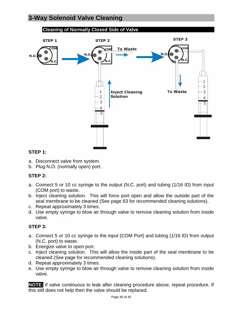
Page 46 of 49
3-Way Solenoid Valve Cleaning
Cleaning of Normally Closed Side of Valve
STEP 1:
a. Disconnect valve from system. b. Plug N.O. (normally open) port.
STEP 2:
a. Connect 5 or 10 cc syringe to the output (N.C. port) and tubing (1/16 ID) from input (COM port) to waste.
b. Inject cleaning solution. This will force port open and allow the outside part of the seal membrane to be cleaned (See page 63 for recommended cleaning solutions).
c. Repeat approximately 3 times. d. Use empty syringe to blow air through valve to remove cleaning solution from inside
valve.
STEP 3:
a. Connect 5 or 10 cc syringe to the input (COM Port) and tubing (1/16 ID) from output (N.C. port) to waste.
b. Energize valve to open port. c. Inject cleaning solution. This will allow the inside part of the seal membrane to be
cleaned (See page for recommended cleaning solutions). d. Repeat approximately 3 times. e. Use empty syringe to blow air through valve to remove cleaning solution from inside
valve. NOTE: If valve continuous to leak after cleaning procedure above, repeat procedure. If this still does not help then the valve should be replaced.

Page 47 of 49
3-Way Solenoid Valve Maintenance (cont.)
Cleaning of Normally Open Side of Valve
STEP 1: a. Disconnect valve from system. b. Plug N.C. (normally closed) port. STEP 2: a. Connect 5 or 10 cc syringe to the input (COM port) and tubing (1/16 ID) from output
(N.O. port) to waste. b. Energize valve to close port. c. Inject cleaning solution. This will force port open and allow the outside part of the
seal membrane to be cleaned (See page for recommended cleaning solutions). d. Repeat approximately 3 times. e. Use empty syringe to blow air through valve to remove cleaning solution from inside
valve. STEP 3:
a. Connect 5 or 10 cc syringe to the output (N.O. Port) and tubing (1/16 ID) from input (COM port) to waste.
b. Inject cleaning solution. This will allow the inside part of the seal membrane to be cleaned (See page for recommended cleaning solutions).
c. Repeat approximately 3 times. d. Use empty syringe to blow air through valve to remove cleaning solution from inside
valve.
NOTE: If valve continuous to leak after cleaning procedure above, repeat procedure. If this still does not help then the valve should be replaced.

Page 48 of 49
3-Way Solenoid Valve Maintenance (cont.) Recommended Cleaning Solutions for Lee Co. Solenoid Valves
After using a system that uses solenoid valves, you might experience mixing of your solutions. This occurs when the solenoid does not seal properly. There are many causes for a solenoid valve to leak.
The best deterrent is to clean the valve thoroughly whenever an experiment is concluded or when there will be a break of longer than 1 day before the valve is used again. In the previous pages there are instructions on how to clean the solenoid valves thoroughly. The type of cleaning solution will depend on the type of solutions that are used in the experiment. Below are some recommended solutions that we use to clean the solenoid valves.
1. Distilled water: For general flushing of valves.
2. Isopropyl Alcohol: For loosening particles that are stuck (due to use of “sticky” solutions) in valve.
3. 5% acidic solution: For removing bacteria or sticky build-up.
4. Acetic acid (i.e. diluted white vinegar): To loosen any build up of minerals in the valve mechanism

Page 49 of 49
Solenoid Valve Limited Warranty
ALA Scientific Instruments agrees to warranty Lee Company Valves for 30 days from date of invoice. The Lee Company certifies the functionality of each valve shipped to ALA Scientific Instruments. The valves are again tested at ALA Scientific when they are incorporated into the different systems that use them. It is recommended that the valves be checked upon receipt to determine any malfunctions. The following are the only agents approved to check valves: distilled water, Nitrogen or purified air. Any other agents used will void the warranty. Valves that have been used in actual experiments cannot be returned. Individual valves that malfunction within 30 days of invoice date will be replaced on a per case basis. ALA Scientific Instruments limits coverage to include repair or replacement of defective materials at our discretion. Buyer is responsible for the cost of return shipment. Inspection upon receipt is essential to receiving coverage should the instrument be damaged in shipment. Generally three days after receipt is the limit for such claims with the shipping company. ALA Scientific Instruments, Inc. is not responsible for damage occurring to, or from, the use of this product that is inconsistent with its intended usage or this manual. It is the buyer’s responsibility to make sure that DC valves used with this instrument are run at the proper voltage and to use common sense in the operation of this product. This instrument, or any of its parts, is not approved for clinical use and has not been produced to such standards. By law it cannot be used on human subjects in any way. It has no clinical applications and is intended as a research instrument only. No guarantee of results is offered or implied by the use of this product. It is intended only for research purposes. Your rights under this warranty may vary from state to state and country to country.