odeon user manual v1 en - ponsel-web.com · ponsel mesure- 35 rue michel marion - 56850 caudan -...
TRANSCRIPT

PONSEL Mesure- 35 Rue Michel MARION - 56850 CAUDAN - FRANCE Tel : +33 (0)2.97.89.25.30 – Fax : +33 (0)2.97.76.55.72
Email : [email protected], wwww.ponsel-web.com
1
ODEON RANGE
Portable field water quality metering and recording device
User guide
Last update: Feb. 2009 V1.1
PONSEL Mesure- 35 Rue Michel MARION - 56850 CAUDAN - FRANCE Tel : +33 (0)2.97.89.25.30 – Fax : +33 (0)2.97.76.55.72
Email : [email protected], wwww.ponsel-web.com
2
CONTENTS
CHAPTER 1 – NOTICES..................................................................................................................3 CHAPTER 2 – GENERAL.................................................................................................................3
2.2 – ODEON - Main functions ......................................................................................................4 2.3 – Additional device features ....................................................................................................4
CHAPTER 3 – TECHNICAL SPECIFICATIONS...............................................................................5 3.1 – ODEON unit - Description ....................................................................................................5 3.2 – Equipment components........................................................................................................6 3.3 – Sensor description................................................................................................................7
3.3.2- PNEPA turbidity/temperature sensor ..............................................................................9 3.3.3- PC4EA conductivity/temperature sensor .......................................................................11 3.3.4- PHRTA pH/Redox/temperature sensor…………………………………………………. 13
CHAPTER 4 – USING THE ODEON ..............................................................................................15 4.1 – Power supply ......................................................................................................................15
4.1.1-Type of batteries authorized ...........................................................................................15 4.1.2-Changing the batteries....................................................................................................15 4.1.3-Rechargeable batteries...................................................................................................15 4.1.4-Prolonged storage or use ...............................................................................................15
4.2 - On/Off, ODEON sleeper mode............................................................................................16 4.3 – Getting familiar with the user interface ...............................................................................17
4.3.1- Navigation pad...............................................................................................................17 4.3.2- Startup screen ...............................................................................................................17 4.3.3- Main screen: MEASURE ...............................................................................................18 4.3.4- General functions...........................................................................................................20
b. Setting DATE and TIME ...................................................................................................21 c.USER configuration ...........................................................................................................22 d. PREFERENCES MENU...................................................................................................23
4.3.5- The SCAN function ........................................................................................................25 4.4- SAVING measurements .......................................................................................................28 4.5- RESULTS display.................................................................................................................35 4.6- Calibrating the parameters. ..................................................................................................36
a- Temperature:....................................................................................................................41 b- Oxygen:............................................................................................................................42 c- pH or Redox: .....................................................................................................................44 d- TURBIDITY and CONDUCTIVITY: ..................................................................................46
CHAPTER 5 – DATA MANAGEMENT: WinTEK Viewer.................................................................49 5.1- ODEON/ PC connection:........................................................................................................49 5.2- Selecting the LOCATION .....................................................................................................50 5.3- Downloading the data...........................................................................................................51 5.4- Viewing the data...................................................................................................................51 5.5- Exporting data to Excel ........................................................................................................53
CHAPTER 6 - SENSORS, ACCESSORIES, CONSUMABLES ......................................................54 6.1 .Sensors: ...............................................................................................................................54 6.2- Accessories. .........................................................................................................................54 6.2- Consumables. ......................................................................................................................54

PONSEL Mesure- 35 Rue Michel MARION - 56850 CAUDAN - FRANCE Tel : +33 (0)2.97.89.25.30 – Fax : +33 (0)2.97.76.55.72
Email : [email protected], wwww.ponsel-web.com
3
CHAPTER 1 – NOTICES Users of ODEON range portable field equipment are invited to read this document in full before using the device. Failure to comply with the instructions provided in this user guide may cause irreparable damage to the equipment (ODEON unit plus digital sensor). This equipment should only be used in the conditions described in this user guide. Use in any other conditions will cause a breakdown of the ODEON-Sensor measurement chain.
CHAPTER 2 – GENERAL
2.1 – Product overview
The ODEON metering and recording device can be linked to one or several NEOTEK-PONSEL sensors to measure the following parameters :
• Temperature (°C) • Dissolved Oxygen ( % SAT, mg/L, ppm) • Turbidity (NTU, FNU) • Conductivity, salinity and TDS-KCl, • pH • Redox
The ODEON is available in 3 versions :
- ODEON CLASSIC : Connects to and recognizes a single specific sensor :
• Oxygen/Temperature, or • Turbidity/Temperature, or • Conductivity/Salinity/Temperature, or • pH / Redox / temperature.
- ODEON OPEN One : recognizes all type of sensors / single probe channel
• Oxygen/Temperature, • Turbidity/Temperature, • Conductivity/Salinity/Temperature • pH / Redox / temperature
- ODEON OPEN X : recognizes all type of sensors (cf OPEN One) / 2 probes channels

PONSEL Mesure- 35 Rue Michel MARION - 56850 CAUDAN - FRANCE Tel : +33 (0)2.97.89.25.30 – Fax : +33 (0)2.97.76.55.72
Email : [email protected], wwww.ponsel-web.com
4
2.2 – ODEON - Main functions
A)- Automatic connected sensor type and serial number recognition. Calibration coefficients for the parameters measured by the sensor plus former calibration history are stored in the sensor itself and are immediately accessible via the ODEON. The default parameters for each type of sensor are measured and immediately displayed. You then have access to an operational measurement chain.
b)- Automatic measurement data refreshing on all selected parameters.
c)- Data recording according to three modes :
• “One-shot” recording mode: Measurement recording on all active parameters by keyboard command,
• Automatic regular recording mode : with manual keyboard start-up,
• Automatic regular recording campaign mode : with campaign beginning and end dates and times. The recorded data are managed in user-named folders (location of measurement campaign, sample name, etc.).
d)- Use the RESULT menu to display each measurement recorded in a specific folder, either in cascade mode or by selecting a measurement number.
e)- Important for traceability: the operator’s identity can be specified. This information will be added to other items, namely in the calibration history.
f)- Automatic sleep mode for increased device autonomy.
2.3 – Additional device features
a)- High level of equipment protection : IP67 watertight warranty when new (not applicable once user has opened the unit, e.g. for battery replacement)
b)- Autonomous equipment powered by 4 alkaline AA batteries or 4 AA NiMH accumulators (optional external recharging cable) or by external 12V power supply (optional external power cable).
c)- PC connection via USB connector with recorded data recovery and display software.

PONSEL Mesure- 35 Rue Michel MARION - 56850 CAUDAN - FRANCE Tel : +33 (0)2.97.89.25.30 – Fax : +33 (0)2.97.76.55.72
Email : [email protected], wwww.ponsel-web.com
5
CHAPTER 3 – TECHNICAL SPECIFICATIONS 3.1 – ODEON unit – Description
Size : 43 / 122 / 205 (H/L/W in mm)
Weight : 560g (without sensor or connecting cable)
Protection factor : IP67.
Storage temperature : -20 to +60°C (-4 to +140°F)
Operating temperature : 0 to +60°C (+32 to +140°F )
Internal power supply : 4 AA alkaline batteries or 4 AA NiMH rechargeable batteries
External power supply: 12V DC by special cable
Inputs: 1 or 2 sensor inputs (6-pin grey metal socket)
1 external power supply or charger input (7-pin black metal socket)
Output : USB connection to PC (7-pin black metal socket)
Connectors
NOTE: Please note the four holes at the back of the unit, designed to allow the pressure sensor within the unit to adjust to atmospheric pressure. A hydrophobic vent in the unit ensures that the unit remains watertight.
Rear view of ODEON
1 or 2 sensor inputs
Grey sockets
Output: Charger power supply inputExternal power supply input
ODEON SERIAL N°
Atmospheric pressureadjustment

PONSEL Mesure- 35 Rue Michel MARION - 56850 CAUDAN - FRANCE Tel : +33 (0)2.97.89.25.30 – Fax : +33 (0)2.97.76.55.72
Email : [email protected], wwww.ponsel-web.com
6
3.2 – Equipment components The ODEON measuring unit is supplied with the following standard items :
N° DESCRIPTION
1 Field case
2 1. ODEON unit and 4 AA alkaline batteries (supplied with new unit)
3 1 carrying strap
4 1 CD with the user guide in PDF format and the WinTek Viewer software (PC application for management and data storage), 1 waterproof user instruction card
5 1 ODEON-PC connector cord (USB)
6 1 or several digital sensors
7 Bottles of calibration solution (as per sensor model supplied)
Optional items and accessories:
2 4 AA NiMH rechargeable batteries (included in the ODEON unit)
8 1 charger for rechargeable NiMH batteries included in the ODEON, and/or 1 12V external power cable
1
2
3
4
6
5
8
7

PONSEL Mesure- 35 Rue Michel MARION - 56850 CAUDAN - FRANCE Tel : +33 (0)2.97.89.25.30 – Fax : +33 (0)2.97.76.55.72
Email : [email protected], wwww.ponsel-web.com
7
3.3 – Sensor description
3.3.1- PODOA : Oxygen/temperature sensor The OPTOD dissolved oxygen sensor operates with optical luminescence measurement technology approved by ASTM International Method D888-05. An oxygen-sensitive layer is lit up with a blue LED. The sensitive material emits a red light (Fluorescence). Its intensity and emission time lag vary according to oxygen concentration. This kind of optical technology requires very few consumables : no membrane replacement, no electrolyte. The DO disk containing the sensitive material needs replacing approximately once every 2 years.
Technical specifications:
Measurement principale Optical luminescence
Measurement ranges 0.00 to 20.00 mg/l or ppm 0 -200% SAT
Resolution 0.01
Accuracy +/- 0.l mg/L or+/- 1 %
Response time (t90) 90% of the value in less than 60 seconds
Water movement No circulation required
Temperature compensation Via CTN
Temperature measurement range 0 - 60°C
Temperature resolution 0.01
Temperature accuracy +/- 0.5 °C
Storage temperature -10°C to + 60°C
Signal interface Modbus RS-485 (SDI-12 optional)
Measurement refresh speed < 1 second max.
Dimensions Diameter: 25 mm; Length without cable: 146 mm Weight 450g (with 3 meter cable)
Material in contact with the medium 316 L Stainless steel
Maximum Pressure 5 bars
Cables/ Connection hardware and software 9-wire shielded cables, polyurethane jacketed, Fischer watertight metal shell connector
Sensor identification Serial No.
Screw-on strainer for capsule replacement

PONSEL Mesure- 35 Rue Michel MARION - 56850 CAUDAN - FRANCE Tel : +33 (0)2.97.89.25.30 – Fax : +33 (0)2.97.76.55.72
Email : [email protected], wwww.ponsel-web.com
8
OPTOD sensor maintenance : -The OPTOD sensor must always be kept clean, particularly in the vicinity of the DO disk. Any trace of biofilm could lead to measurement errors. -After each use, rinse the sensor before storing. -If the membrane is dirty, clean the sensor head with warm water and soapy water. Use a sponge, but never use abrasive sponges with a scouring pad. Rinse the sensor before storing.
Oxygen Calibration : The OPTOD sensor is an optical sensor which only requires an annual calibration. Using a clean sensor, periodically check the 0 % Sat value by immersing the sensor in a water/sulphite solution (sulphite concentration: < 2%). If the zero point is offset, perform a complete calibration of the sensor. Caution: do not leave the sensor in contact with the sulphite solution for more than one hour. The 2-point calibration is performed with a sulphite solution (offset). After rinsing and drying, the sensor’s slope is calculated by exposing the sensor to humid oxygen saturated air. Temperature Calibration:
Temperature sensor calibration is performed once a year in two stages: • stage 1 (offset): the sensor is placed in a container filled with water and ice, • stage 2 (slope): The sensor is placed in a medium (air or thermostat-controlled water) with a known temperature. This temperature will be measured using a certified thermometer.
Changing the DOdisk :
If you notice an offset in measurements during use, clean the sensor and calibrate it. If calibration cannot be performed, change the membrane support containing the sensitive material, proceed as follows :
• Unscrew the stainless steel strainer, • Remove the DOdisk fitted onto an optical window. If this operation proves difficult (membrane stuck to the optical window), immerse the sensor in a little water to moisten the membrane and try removing the DOdisk using a small tip.
Do not use a sharp object or screwdriver. This could scratch the optical window.
• Once the membrane is removed, be careful not to touch the optical window and reposition the DOdisk onto the optical window with the red side facing the window. The size of the disk is perfectly adjusted to fit the optical window. • Refit the stainless steel strainer onto the sensor head and screw back on.
T°C sensor
Optical window Stainless steel strainer
DO disk (Upside)

PONSEL Mesure- 35 Rue Michel MARION - 56850 CAUDAN - FRANCE Tel : +33 (0)2.97.89.25.30 – Fax : +33 (0)2.97.76.55.72
Email : [email protected], wwww.ponsel-web.com
9
3.3.2- PNEPA : Turbidity/temperature sensor The measurement principle of the turbidity sensor is based on nephelometry: A LED emits an infrared light (880nm) and a receiver diode placed at an angle of 90° measures the light radiation emitted (standardized measurement). You can calibrate the sensor using a Formazine standard. This optical technology is a very cost-effective solution requiring little maintenance and no consumables (non-aggressive lens cleansing).
Technical specifications:
Measurement principle / Nephelometry 90° IR emission ISO 7027 compliance
Measurement ranges
0 to 4000 NTU in 4 ranges : 0.00 – 50.00 NTU 0.0 – 200.0 NTU 0 – 1000 NTU 0 – 4000 NTU
Resolution 0.01 to 1 according to NTU range
Accuracy +/-1 % of the full scale per range
Response time < 5 s
Operating temperature 0°C to +50°C
Temperature compensation Via CTN
Temperature measurement range 0 - 60°C
Temperature resolution 0.01
Temperature accuracy +/- 0.5 °C
Storage temperature -10°C to + 60°C
Signal interface Modbus RS-485 (SDI-12 optional)
Measurement refresh speed < 1 second max.
Dimensions Diameter: 27 mm; Length without cable: 170 mm Weight 300g (with 3 meter cable)
Material in contact with the medium PVC, PMMA, Nickel-coated bronze
Maximum Pressure 5 bars
Cables/ Connection hardware and software 9-wire shielded cables, polyurethane jacketed, Fischer watertight metal shell connector
Sensor identification Serial No.
Measuring head with optical fibers

PONSEL Mesure- 35 Rue Michel MARION - 56850 CAUDAN - FRANCE Tel : +33 (0)2.97.89.25.30 – Fax : +33 (0)2.97.76.55.72
Email : [email protected], wwww.ponsel-web.com
10
NTU sensor maintenance: Keep the NTU sensor clean, particularly the head containing the optical fibers. Any trace of biofilm or dirt could lead to measurement errors. After each use, rinse the sensor before storing. If the sensor head is dirty, clean it with a little warm water and soapy water. Use a sponge, but never use abrasive sponges with a scouring pad. Rinse the sensor before storing.
Turbidity Calibration:
The NTU sensor is an optical sensor requiring little calibration. Using a clean sensor, periodically check the NTU 0 value by immersing the sensor in still distilled water. If the 0 point is offset, perform a complete calibration of the sensor. To do this, you need a Formazine solution with a concentration equal to half the measurement range. Prepare the solution by using a stock solution at 4000 NTU.
To prepare the solution, use a 200mL volumetric flask. Add the required volume of Formazine (see table below) and make up to 200 mL with distilled water. Formazine solution with concentrations below 1 000 NTU degrade quite quickly. Do not keep the solution for several days. The 2000 NTU solution can be stored for 2 to 3 weeks in an opaque bottle in the refrigerator.
Measurement range Formazine calibration solution concentration
Volume of Formazine (mL)
0.0 – 50.0 NTU 25 NTU 1.25 mL
0.0 – 200.0 NTU 100 NTU 5 mL
0 – 1000 NTU 500 NTU 25 mL
0 – 4000 NTU 2000 NTU 100 mL
Temperature Calibration:
Temperature sensor calibration is performed once a year in two stages:
• stage 1 (offset): the sensor is placed in a container filled with water and ice, • stage 2 (slope): The sensor is placed in a medium (air or thermostat heated bath water) with a known temperature. This temperature will be measured using a certified thermometer.
PONSEL Mesure- 35 Rue Michel MARION - 56850 CAUDAN - FRANCE Tel : +33 (0)2.97.89.25.30 – Fax : +33 (0)2.97.76.55.72
Email : [email protected], wwww.ponsel-web.com
11
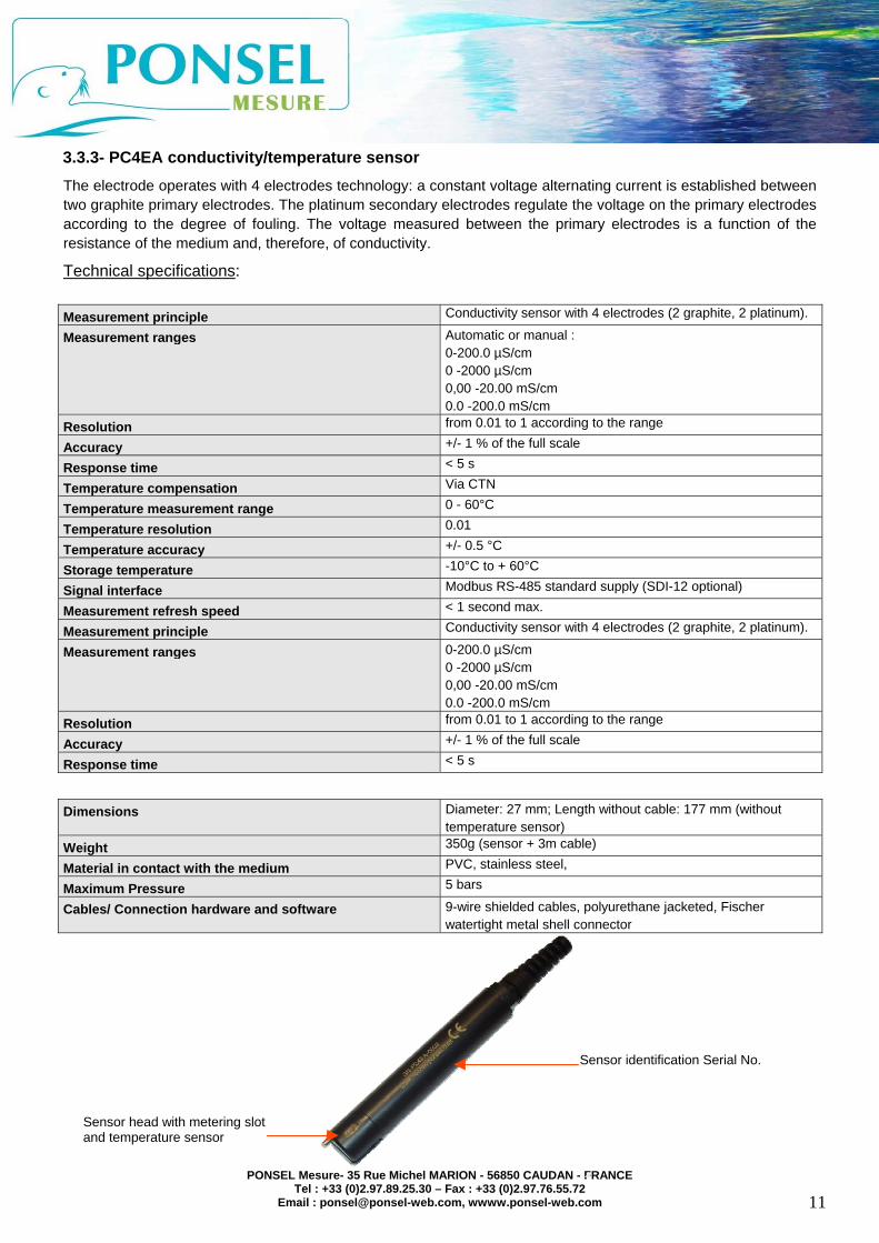
3.3.3- PC4EA conductivity/temperature sensor The electrode operates with 4 electrodes technology: a constant voltage alternating current is established between two graphite primary electrodes. The platinum secondary electrodes regulate the voltage on the primary electrodes according to the degree of fouling. The voltage measured between the primary electrodes is a function of the resistance of the medium and, therefore, of conductivity.
Technical specifications: Measurement principle Conductivity sensor with 4 electrodes (2 graphite, 2 platinum).
Measurement ranges Automatic or manual : 0-200.0 µS/cm 0 -2000 µS/cm 0,00 -20.00 mS/cm 0.0 -200.0 mS/cm
Resolution from 0.01 to 1 according to the range
Accuracy +/- 1 % of the full scale
Response time < 5 s
Temperature compensation Via CTN
Temperature measurement range 0 - 60°C
Temperature resolution 0.01
Temperature accuracy +/- 0.5 °C
Storage temperature -10°C to + 60°C
Signal interface Modbus RS-485 standard supply (SDI-12 optional)
Measurement refresh speed < 1 second max.
Measurement principle Conductivity sensor with 4 electrodes (2 graphite, 2 platinum).
Measurement ranges 0-200.0 µS/cm 0 -2000 µS/cm 0,00 -20.00 mS/cm 0.0 -200.0 mS/cm
Resolution from 0.01 to 1 according to the range
Accuracy +/- 1 % of the full scale
Response time < 5 s
Dimensions Diameter: 27 mm; Length without cable: 177 mm (without
temperature sensor) Weight 350g (sensor + 3m cable)
Material in contact with the medium PVC, stainless steel,
Maximum Pressure 5 bars
Cables/ Connection hardware and software 9-wire shielded cables, polyurethane jacketed, Fischer watertight metal shell connector
Sensor identification Serial No.
Sensor head with metering slot and temperature sensor

PONSEL Mesure- 35 Rue Michel MARION - 56850 CAUDAN - FRANCE Tel : +33 (0)2.97.89.25.30 – Fax : +33 (0)2.97.76.55.72
Email : [email protected], wwww.ponsel-web.com
12
C4E sensor maintenance: The C4E sensor operates with 4 electrodes. These electrodes must be maintained in optimal working condition. After each use, rinse the sensor before storing. To clean the graphite or platinum electrodes, run an abrasive band through the metering slot under running water.
Conductivity calibration: Conductivity sensor calibration is performed in two stages :
• stage 1 (offset): the sensor is exposed to air, • stage 2 (slope): the sensor is placed in a buffer solution with a known conductivity.
Measurement range Calibration solution concentration
0.0 / -200.0 µS/cm 84 µS/cm
0 / -2000 µS/cm 1413 µS/cm
0.00 - 20.00 mS/cm 12,880 µS/cm
0.0 - 200.0 mS/cm 111.8 mS/cm
Temperature Calibration:
Temperature sensor calibration is performed once a year in two stages:
• stage 1 (offset): the sensor is placed in a container filled with water and ice, • stage 2 (slope): The sensor is placed in a medium (air or thermostat-controlled water) with a known temperature. This temperature will be measured using a certified thermometer.

PONSEL Mesure- 35 Rue Michel MARION - 56850 CAUDAN - FRANCE Tel : +33 (0)2.97.89.25.30 – Fax : +33 (0)2.97.76.55.72
Email : [email protected], wwww.ponsel-web.com
13
3.3.4- PHRTA pH/Redox/temperature sensor The dual stage PONSEL pH/Redox/T°C sensor consists of :
- an electronic part
- a “consumable” part
The sensor is dual stage on delivery and only the consumable part requires replacement when the calibration gel is depleted.
The measurement principle includes an Ag/AgCl reference electrode with PLASTOGEL® KCI saturated plasticized electrolyte used for pH and Redox measurements The Plastogel® electrolyte is in direct contact with the external environment without the use of capillary or porous material. There is therefore no danger of blockage or unpriming of the calibration material. The measurement electrodes come in the shape of special pH sensitive glass phials welded to the end of a crystal tube, for pH measurements, and platinum tips for Redox. Temperature measurement is performed via CTN inserted in a stainless steel houding. pH measurement Measurement principle pH/Reference combined electrode: Special glass, Ag/AgCl
Reference Gelled electrolyte (KCI) Measurement ranges 0 – 14 pH
Resolution 0.01 pH
Accuracy +/- 0.1 pH
ORP measurement
ORP measurement principle Redox/Reference combined electrode: Platinum tip, Ag/AgCl Reference Gelled electrolyte (KCI)
Measurement range -1000 to +1000 mV
Resolution 0.1 mV
Accuracy ± 2 mV
Temperature measurement
Temperature measurement principle CTN
Operating temperature 0.00 °C to 60.00°C
Resolution 0.01 °C
Accuracy ±0.5 °C
GENERAL
Storage temperature -10°C to + 60°C
Signal interface Modbus RS-485 standard supply (SDI-12 optional)
Measurement refresh speed < 1 second max. Dimensions Electronic parts: Diameter = 27 mm ; Length without
cable: 159 mm Consumables: Diameter = ; Length =
Weight 380 g (with 3 meter cable) Material in contact with the medium PVC, special pH glass, platinum
Maximum Pressure 5 bars
Cables/ Connection hardware and software 9-wire shielded cables, polyurethane jacketed, Fischer watertight metal shell connector

PONSEL Mesure- 35 Rue Michel MARION - 56850 CAUDAN - FRANCE Tel : +33 (0)2.97.89.25.30 – Fax : +33 (0)2.97.76.55.72
Email : [email protected], wwww.ponsel-web.com
14
Sensor – disassembled Sensor Assembled
pH/EH sensor maintenance :
The glass pH measurement ball in the pH sensor must be kept as clean as possible. If dirty, wash the glass pH measurement ball in soapy water and rinse before storage or use. If this is not enough, soak the sensor in a special cleansing solution overnight, then rinse before use. As far as possible, avoid any contact between the glass ball and oil, hydrocarbons or colloids. To clean the Redox sensor, run an abrasive band over the platinum tip under running water. pH calibration: pH sensor calibration is performed in two stages:
• stage 1 (offset): Place the sensor in a pH 7.01 buffer solution. • stage 2 (slope): Place the sensor in a pH 4.01 (or 9.01 or 10.01) buffer solution.
Redox calibration: • Redox sensor calibration is performed in two stages: • stage 1 (offset): Expose the sensor to the air to set the 0 mV value • stage 2 (slope): Place the sensor in a 240 mV (or 470 mV) buffer solution.
Temperature Calibration: Temperature sensor calibration is performed once a year in two stages:
• stage 1 (offset): Place the sensor in a container filled with water and ice, • stage 2 (slope): Place the sensor in a medium (air or thermostat-controlled heated water) with a known temperature. This temperature will be measured using a certified thermometer.
Electronic part with cable
Tightening ring linking electronic part and consumable
Replaceable cartridge containing pH, Redox and temperature measurement devices. Part to be changed once reference gel supply exhausted
Pastille of Platinium for ORP measurerment
Temperature sensor Glass electrode

PONSEL Mesure- 35 Rue Michel MARION - 56850 CAUDAN - FRANCE Tel : +33 (0)2.97.89.25.30 – Fax : +33 (0)2.97.76.55.72
Email : [email protected], wwww.ponsel-web.com
15
CHAPTER 4 – USING THE ODEON
4.1 – Power supply
4.1.1-Type of batteries authorized
Users should never combine different types of batteries or connect a charger to an ODEON fitted with alkaline batteries. This could cause a fire hazard or explosions.
4.1.2-Changing the batteries Used AA alkaline batteries should always be replaced in a clean, dry place, to avoid any dirt entering the unit housing. The operator must first check that the batteries or rechargeable batteries are correctly positioned in the battery compartment (positive and negative polarity). When closing the unit housing, the operator should check:
• that the power cable between the battery unit and the electronic card is not caught, • that the seal between the two halves of the housing is in place, • that all 6 screws are tightened so that the seal is crushed between the two parts of the housing.
Inadequate tightening will result in ODEON malfunction or leakage into the unit.
The operator must also regularly check the batteries to avoid equipment damage due to old batteries.
4.1.3- Rechargeable batteries The 4 NiMH rechargeable batteries in the ODEON can be recharged without removing them from the unit. Use only the recharging cable supplied by the manufacturer. The unit housing may feel slightly warm during the recharging operation: this is normal.
Users will note that the charger supplied with the ODEON is not watertight. Do not use in a damp environment (field work measurements) but only in laboratory conditions.
The ODEON-PC USB connector is also designed for office use, not outdoor use. Users shall be entirely liable for any problems encountered while transferring data to a portable computer in the field (in damp environments).
4.1.4- Prolonged storage or use NiMH accumulators will lose power when not in use. Before starting a measurement campaign, uses should check the charge level indicated by the icon displayed in the upper right-hand corner of the screen.
If the output voltage of the batteries or accumulators is too low, the screen will start blinking, then the unit will cut out altogether. However, any data already saved will remain safe.
When preparing for a long measurement campaign, users should fit new alkaline batteries or recharge the accumulators. Users may also connect the ODEON to an external 12V source via the optional connector cord.

PONSEL Mesure- 35 Rue Michel MARION - 56850 CAUDAN - FRANCE Tel : +33 (0)2.97.89.25.30 – Fax : +33 (0)2.97.76.55.72
Email : [email protected], wwww.ponsel-web.com
16
4.2 - On/Off, ODEON sleeper mode
On : Simply press the On/Off key to enable the measurement unit.
COMMENT: Should the unit fail to start, users should check the power supply (batteries or rechargeables correctly installed in the battery unit).
Backlight : When the ODEON is on, press ON again to activate the screen backlight. The backlight stays on as long as the operator uses the keyboard. If the keyboard is no longer used, the backlight goes off after a time lag defined by the manufacturer. However, you can switch off the backlight by pressing the ON/OFF switch once again.
Off To switch off the ODEON completely, keep the ON/OFF key pressed down for 10 seconds.
Standby mode If no key is pressed for 30 seconds (factory default value), the unit automatically switches to sleeper mode. The screen becomes blank and no measurements are carried out. However, if the automatic record function is enabled, measurements will be performed and saved according to the pre-defined frequency.
To reactivate the screen, simply press any key.
You can adjust the standby time yourself (see the Chapter entitled “Using the user interface”).

PONSEL Mesure- 35 Rue Michel MARION - 56850 CAUDAN - FRANCE Tel : +33 (0)2.97.89.25.30 – Fax : +33 (0)2.97.76.55.72
Email : [email protected], wwww.ponsel-web.com
17
4.3 – Getting familiar with the user interface
4.3.1- Navigation pad KEY 1: On/Off; backlight enable/disable
KEY 2: OK key to validate choices and actions.
KEY 3: DEL, deletes selected letters
KEY 4: ESC, returns to previous window
KEY 5: Navigation arrows
4.3.2- Startup screen When the ODEON is switched on, the startup screen displays both the unit software and hardware.
N° Description 1 ODEON serial number 2 ODEON version:
- CLASSIC Range (dedicated to one sensor): Classic OPTOD Classic NTU Classic PHEHT Classic C4E - OPEN Range (Open One with 1 sensor input and X with 2 sensor inputs).
3 Software version
KEY 1
KEY 2
KEY 3
KEY 4
KEY 5
NEOTEK-PONSEL SN-ODEOA-0003
Open v 1.2.1
1
2 3

PONSEL Mesure- 35 Rue Michel MARION - 56850 CAUDAN - FRANCE Tel : +33 (0)2.97.89.25.30 – Fax : +33 (0)2.97.76.55.72
Email : [email protected], wwww.ponsel-web.com
18
4.3.3- Main screen: MEASURE
If connected to a single sensor which is already recognized, the ODEON directly displays the active parameters with additional data in the shape of icons or text. ZOOM mode is enabled. The measurement selected by the operator will be displayed in enlarged format among all the active parameters.
N° Description 1 Progress bar : saves current measurement 2 Localization enabled 3 Save mode 4 Number of data items saved 5 Measured atmospheric pressure 6 MODBUS address for the connected sensor 7 Name of active parameter 8 Measurement unit recall on ZOOM 9 Shortcuts Direct access to main functions 10 Activation of occasional save mode and manual start 11 ZOOM on parameter measurement 12 Parameter unit 13 Symbol: Information on state of measurement or
sensor 14 Date and Time 15 Current user identification 16 Battery charge level 17 USB logo: PC connection enabled
- ZOOM on a measurement:
To enable the ZOOM function, place the cursor on the measurement required and use the UP, DOWN, RIGHT and LEFT arrows. Then press OK to enable ZOOM. The operator can now access all displayed measurements.

PONSEL Mesure- 35 Rue Michel MARION - 56850 CAUDAN - FRANCE Tel : +33 (0)2.97.89.25.30 – Fax : +33 (0)2.97.76.55.72
Email : [email protected], wwww.ponsel-web.com
19
DISPLAY message associated with a symbol : Use the UP, DOWN, RIGHT and LEFT arrows to position the cursor on the selected symbol. Then press OK to display the message. Press ESC to return to MEASUREMENT window
Symbol Meaning
# Sensor using factory default coefficients
? Sensor malfunction or connection problem
! Measurement alert
- DISPLAY measurements for several sensors
If equipped with two sensor connectors or connected to several sensors via the appropriate equipment (multiple sensor probe or junction box) the ODEON unit can display data from several sources. The MODBUS address for each connected sensor is displayed on the left of the screen. In this case, the ZOOM mode is disabled.
DISCONNECTING a sensor
If the operator disconnects a sensor or if the connection is down the measurement value is replaced on screen by a line of slashes The ? symbol is simultaneously displayed. Placing the cursor on the symbol will display a message.

PONSEL Mesure- 35 Rue Michel MARION - 56850 CAUDAN - FRANCE Tel : +33 (0)2.97.89.25.30 – Fax : +33 (0)2.97.76.55.72
Email : [email protected], wwww.ponsel-web.com
20
4.3.4 - General functions
a. Selecting a LANGUAGE. ODEON operating instructions and messages are available in French, English, German, Spanish, Italian and Polish.
Use the MENU shortcut on the main screen to access the GENERAL MENU. Press OK to confirm.
Place the cursor on CONFIGURATION and press OK.
Place the cursor on the LANGUAGES tab then press OK.
Use the up/down arrows to move the cursor and press OK to select a language. The symbol indicates the active language.
Press ESC to return to previous menu.

PONSEL Mesure- 35 Rue Michel MARION - 56850 CAUDAN - FRANCE Tel : +33 (0)2.97.89.25.30 – Fax : +33 (0)2.97.76.55.72
Email : [email protected], wwww.ponsel-web.com
21
b. Setting DATE and TIME
Use the MENU shortcut on the main screen to access the GENERAL MENU. Press OK to validate.
Place the cursor on CONFIGURATION and press OK.
Place the cursor on the DATE/TIME tab and press OK.
Use the up/down arrows to move the cursor and press OK to select the item you want to change.
Increment by using the up/down arrows then press OK.
Select the date format required then press OK The symbol indicates the active format.
Press ESC to return to previous menu.

PONSEL Mesure- 35 Rue Michel MARION - 56850 CAUDAN - FRANCE Tel : +33 (0)2.97.89.25.30 – Fax : +33 (0)2.97.76.55.72
Email : [email protected], wwww.ponsel-web.com
22
c. USER configuration Use the MENU shortcut on the main screen to access the GENERAL MENU. Press OK to confirm. Place the cursor on CONFIGURATION and press OK. Place the cursor on the USER tab then press OK.
- CREATING a USER
Select New User to access a location definition (11 characters maximum). You can also access a default "USER" file.

PONSEL Mesure- 35 Rue Michel MARION - 56850 CAUDAN - FRANCE Tel : +33 (0)2.97.89.25.30 – Fax : +33 (0)2.97.76.55.72
Email : [email protected], wwww.ponsel-web.com
23
Use the up/down and right/left arrows to move the cursor over the alphanumerical characters. Press OK to select a character.
Press DEL to delete a character.
Select VALID and press OK to end selection. “NEW USER CREATED” is displayed and the new user is activated in the user list
“USER ALREADY CREATED” indicates that the list already contains an identical name. If this is the case, either change the name or press ESC to exit. - DELETING a USER
To delete a User, select the name in the list and press DEL. You cannot delete the active User. If the list already contains 10 User names, you need to delete one before creating a new User. The ODEON will request confirmation for each deletion to avoid measurement campaign data being deleted accidentally. Select YES or NO using the right/left arrows then press OK to confirm.
“ERASING IN PROGESS” will be displayed and the ODEON automatically returns to the previous screen.
d. PREFERENCES MENU
Use the up/down arrows to select the PREFERENCES menu tab then press OK.

PONSEL Mesure- 35 Rue Michel MARION - 56850 CAUDAN - FRANCE Tel : +33 (0)2.97.89.25.30 – Fax : +33 (0)2.97.76.55.72
Email : [email protected], wwww.ponsel-web.com
24
- DISPLAY menu. Screen sleeper mode Use the up/down arrows to select the DISPLAY menu tab, then press OK.
- DISPLAY menu. Screen sleeper mode Use the up/down arrows to increment the time lag after which the screen automatically goes into sleeper mode. The time lag is in increments of 10 seconds. The default time lag is 30 seconds. Above 60, the counter jumps to 999, indicating that the screen sleeper function is disabled. Disabling the screen sleeper mode is not recommended as this may reduce the ODEON’s autonomy. Press OK to confirm. The ODEON will automatically return to the previous screen.
- FACTORY CONFIGURATION Menu: Restoring the factory configuration. Use the left/right arrows to select factory configuration then press OK.
Warning: restoring factory configuration means you will lose the user list, the location list and all associated records, and the screen sleeper settings.
The screen displays “Factory config in progress" then returns to the measurement screen.

PONSEL Mesure- 35 Rue Michel MARION - 56850 CAUDAN - FRANCE Tel : +33 (0)2.97.89.25.30 – Fax : +33 (0)2.97.76.55.72
Email : [email protected], wwww.ponsel-web.com
25
4.3.5- The SCAN function
The ODEON allows you to display and save all measurements performed by the sensors currently connected and identified. The identification of all connected sensors is mandatory and corresponds to the MODBUS SCAN function. The ODEON sends a request to each of the MODBUS addresses in turn. Any sensor that is both active and compatible is then recorded in the ODEON's sensor data base. - Enabling SCAN: In the main MEASUREMENT screen, place the cursor on the SCAN shortcut then press OK. The SCAN MODBUS IN PROGRESS windows will open. All the MODBUS addresses will scroll down during the SCAN process. Press ESC to interrupt the SCAN. If the ODEON fails to detect a sensor or if the SCAN process has been interrupted before it could detect the connected sensors, the following message will be displayed: A new line appears every time an active sensor is identified, with its address and description. Press ESC to interrupt the SCAN when all connected sensors have been identified.

PONSEL Mesure- 35 Rue Michel MARION - 56850 CAUDAN - FRANCE Tel : +33 (0)2.97.89.25.30 – Fax : +33 (0)2.97.76.55.72
Email : [email protected], wwww.ponsel-web.com
26
- DISPLAYING the full sensor description
Use the UP and DOWN arrows to select a sensor in the SCAN RESULT window. Press OK to display the PROBE INFO. Press ESC to exit.
Press ESC to exit SCAN RESULT and return to the main screen.
4.3.6- SELECTING parameters displayed
You can select accessible parameters in the list displayed for each connected sensor. For example, the optical oxygen sensor provides 4 parameters:
• Temperature • Oxygen as a % of saturation, • Oxygen in mg/L, • Oxygen in ppm.
Use the shortcut on the main screen to access the GENERAL MENU. Press OK to confirm. Place the cursor on CONFIGURATION and press OK. Place the cursor on the PARAMETERS tab then press OK.

PONSEL Mesure- 35 Rue Michel MARION - 56850 CAUDAN - FRANCE Tel : +33 (0)2.97.89.25.30 – Fax : +33 (0)2.97.76.55.72
Email : [email protected], wwww.ponsel-web.com
27
A full description of the sensor with its available parameters will be displayed for each connected sensor.
Use the up/down arrows and press OK to select or deselect one or more parameters in the list. The symbol indicates an active parameter. Press OK to confirm the full parameter selection when the cursor is on VALID.
The VALID instruction will be replaced by DONE.
Press ESC to return to previous menu. If the configured parameters are different from the original parameters, an alert message is displayed.
The ODEON warns you that the settings have been changed and disables the current save functions. Any new data will have to be saved to a new location (see chapter 4.5).
Select Previous Page or Next Page and press OK to access the list of available parameters for another connected sensor (the conductivity/temperature sensor, for instance).
In the case of conductivity and turbidity sensors, you must select the work range as well as the parameters. Select 1 of the 4 set ranges or the automatic range switching function in the left-hand column, then press OK (2).
Press OK to confirm the selection when the cursor Is on VALID (CONFIRM SELECTION). Press ESC to return to previous menu.
- ODEON connected to more than 2 sensors: You can select up to 4 parameters simultaneously for each connected sensor. However, the main measurement screen can only display 8 parameters (8 lines). If your ODEON is connected to a network of more than 2 sensors, you will therefore have to limit the number of parameters you can select.

PONSEL Mesure- 35 Rue Michel MARION - 56850 CAUDAN - FRANCE Tel : +33 (0)2.97.89.25.30 – Fax : +33 (0)2.97.76.55.72
Email : [email protected], wwww.ponsel-web.com
28
4.4- SAVING measurements
You can save measurements in 20 different folders, identified according to LOCATION. When you create a location, the current configuration (list of identified sensors and active parameters) is automatically associated with the new location. A new location must be activated before data can be recorded. You can select different recording modes:
- SNAPSHOT: Once you have defined the location, you can save the measurement displayed on the main screen at any time. - AUTO PROGRAMMED : Once you have defined the location, you must define the recording campaign beginning and end dates along with measurement frequency. - AUTO MAN. START : In this case, the recording mode is also automatic. You only need to define acquisition frequency. Press OK in the main MEASURE screen to start the recording campaign. Data acquisition will continue until the batteries run down or the memory is full.
ATTENTION: when the recording is activated, stay on the MEASURE screen.
- DEFINING or ACTIVATING a location:
You can access the RECORDING menu via the REC shortcut in the main screen.
or by selecting the RECORDING tab in the GENERAL menu and pressing OK.
Press ESC to return to the previous screen.
Place the cursor on the LOCALISATION tab then press OK.
Press ESC to return to the previous screen.

PONSEL Mesure- 35 Rue Michel MARION - 56850 CAUDAN - FRANCE Tel : +33 (0)2.97.89.25.30 – Fax : +33 (0)2.97.76.55.72
Email : [email protected], wwww.ponsel-web.com
29
You can create a new location or select a location in the list.
- ACTIVATING a LOCALISATION in the list Use the up/down arrows to select an existing location. Press OK to activate the location before defining a recording campaign. When you have selected more than 7 locations, use the right/left arrows to navigate between the pages. (1).
- CREATING a LOCALISATION
Press OK on NEW LOCALISATION to access a location definition (8 characters maximum). You can also access a default "local" file.
Select the alphanumerical characters you need by using the up/down and right/left arrows. Press OK to select a character. Press DEL to delete a character.
Select VALID then press OK to end selection. “NEW LOCALISATION CREATED” is displayed and the new location is directly activated in the user list
“LOCALISATION ALREADY EXISTS” indicates that the list already contains an identical name. If this is the case, either change the name or press ESC to exit.
- DELETING a LOCATION
Press DEL on a location in the list to delete the location and all associated data. You cannot delete the active location. If the list already contains 20 Location names, you need to delete one before creating a new Location. The ODEON will request confirmation for each deletion to avoid measurement campaign data being deleted accidentally.

PONSEL Mesure- 35 Rue Michel MARION - 56850 CAUDAN - FRANCE Tel : +33 (0)2.97.89.25.30 – Fax : +33 (0)2.97.76.55.72
Email : [email protected], wwww.ponsel-web.com
30
- RECORDING in ON-SHOT mode:
Select the PONCTUEL tab in the ENREGISTREMENT menu then press OK to confirm.
This displays the LOCALISATION presentation screen. Select a file to save the recording data. Use the up/down arrows to select an existing location. Press OK to activate the location before defining a recording campaign. Two cases are possible: - Case N°1: The sensor configuration and the selected location configuration are different. Press ESC to return to the LOCALISATION selection screen. You can also chose another LOCALISATION, with a configuration identical to that of the connected sensors, or create a new location.
- Case N°2: The configuration for the connected sensor(s) is identical to that of the selected LOCALISATION (same number of parameters, same parameter, same measurement unit and unit range). Select the memory operating mode then press OK :
FIXED memory Recording stops once the memory is full, FIFO (Revolving) memory: Once the memory is full, data recording continues by deleting the first data for the current location (for example: POND-1 (BASSIN-1)).
The REC MAX line indicates the number of recordings available Select VALID (CONFIRM SELECTION) to enable 'one-shot' mode. Press ESC to return to the previous screen.

PONSEL Mesure- 35 Rue Michel MARION - 56850 CAUDAN - FRANCE Tel : +33 (0)2.97.89.25.30 – Fax : +33 (0)2.97.76.55.72
Email : [email protected], wwww.ponsel-web.com
31
“SNAP” indicates the 'SNAPSHOT' recording mode in the main screen (1).
The cursor moves to the center of the symbol in the shortcut bar (2). Simply press OK to record the measurement. You can see the recording in progress in the progress bar at the top of the screen (3). A meter (4) allows you to see the volume of data recorded for the current location.
The SNAPSHOT recording mode can be interrupted in the RECORDING menu (via the REC shortcut).
Press OK to toggle between ACTIVE and INACTIVE.
- RECORDING, AUTO mode, MANUAL START: This mode allows you to save all the measurements for a campaign at regular intervals, without time limitation. It is up to the user to initiate the first recording manually.
In the RECORDING menu, first select the LOCALISATION tab to enable or to create a localisation. Then chose the AUTO MA. START tab.
This displays the LOCALISATION presentation screen. Select a file to save the recording data. Use the up/down arrows to select an existing location. Press OK to activate the location before defining a recording campaign.

PONSEL Mesure- 35 Rue Michel MARION - 56850 CAUDAN - FRANCE Tel : +33 (0)2.97.89.25.30 – Fax : +33 (0)2.97.76.55.72
Email : [email protected], wwww.ponsel-web.com
32
Two cases are possible:
- Case N°1: The sensor configuration and the selected LOCALISATION configuration are different. Press ESC to return to the LOCALISATION selection screen. You can also chose another LOCALISATION, with a configuration identical to that of the connected sensors, or create a new location.
- Case N°2: The configuration for the connected sensor(s) is identical to that of the selected LOCALISATION (same number of parameters, same parameter, same measurement unit and unit range).
Use the up/down arrows to select a line, and then press OK to enable a line. Use the right/left arrows to move sideways on the FREQUENCY line and the up/down arrows to increment the values. Press OK to confirm. The ODEON unit displays the campaign end date, calculated on the basis of the memory remaining available.
You must also decide whether the memory mode will be FIXED or FIFO (Revolving) Press OK to enter the line and use the up/down arrows to toggle FIXED/FIFO. Press OK to confirm.
Select VALID and press OK to enable automatic mode Manual start. Press ESC to return to the previous screen.
“WAIT” indicates the ‘auto' recording mode in the main screen (1).
The cursor moves to the center of the OK button in the shortcut bar (2). Press OK to initiate the first recording of the measurement campaign. You can see the recording in progress in the progress bar at the top of the screen (1).
The ‘WAIT' abbreviation changes to "AUTO" [2]. The ODEON records the measurements according to the frequency defined.
A meter [3] allows you to see the volume of data recorded for the current location.

PONSEL Mesure- 35 Rue Michel MARION - 56850 CAUDAN - FRANCE Tel : +33 (0)2.97.89.25.30 – Fax : +33 (0)2.97.76.55.72
Email : [email protected], wwww.ponsel-web.com
33
The automatic recording mode with manual start can be interrupted in the RECORDING menu (via the REC shortcut).
Press OK to toggle between ACTIVE and INACTIVE.
- RECORDING, AUTO PROGRAMMED mode, with pre-programmed start and end dates: This mode allows users to record measurements at regular intervals for a campaign that starts and ends at a pre-determined date.
In the RECORDING menu, first select the LOCALISATION tab to enable or to create a location. Then chose the Dep. MANUEL (MANUAL start) tab. AUTO:
This displays the LOCALISATION presentation screen. Select a file to save the recording data. Use the up/down arrows to select an existing location. Press OK to activate the location before defining a recording campaign. Two cases are possible: - Case N°1: The sensor configuration and the selected location configuration are different. Press ESC to return to the LOCALISATION selection screen. You can also chose another LOCALISATION, with a configuration identical to that of the connected sensors, or create a new localisation.

PONSEL Mesure- 35 Rue Michel MARION - 56850 CAUDAN - FRANCE Tel : +33 (0)2.97.89.25.30 – Fax : +33 (0)2.97.76.55.72
Email : [email protected], wwww.ponsel-web.com
34
- Case N°2: The configuration for the connected sensor(s) is identical to that of the selected LOCALISATION (same number of parameters, same parameter, same measurement unit and unit range). Use the up/down arrows to move the cursor and press OK to select the item you want to change. Use the right/left arrows to move on the selected line, then increment with the up/down arrows. Press OK to confirm. The user sets:
- the time and date the recording campaign is started, - the time and date the recording campaign is completed, - the acquisition frequency (minimum 10 seconds), - the set or revolving memory.
The Odeon displays the maximum recording capacity and the number of pre-set recordings on the basis of the user-defined parameters. Select VALID and press OK to enable automatic recording programmed. Press ESC to return to previous menu. The first recording for the pre-set date and time is displayed in the progress bar at the top of the screen [1]. “AUTO” indicates current recording mode [2]. The ODEON records the measurements according the frequency defined. A meter [3] allows you to see the volume of data recorded for the current location.

PONSEL Mesure- 35 Rue Michel MARION - 56850 CAUDAN - FRANCE Tel : +33 (0)2.97.89.25.30 – Fax : +33 (0)2.97.76.55.72
Email : [email protected], wwww.ponsel-web.com
35
4.5- RESULTS display You can display the date recorded in the files created under the LOCALISATION tab. A total of 20 files can be saved. Use the MENU shortcut on the main screen to access the MAIN MENU. Press OK to confirm.
Use the up/down arrows to select RESULTS then press OK.
Use the up/down arrows to select the file you want to display, then press OK.
If no measurements have been recorded, the ODEON unit displays NO RECORD on the RESULTS page.

PONSEL Mesure- 35 Rue Michel MARION - 56850 CAUDAN - FRANCE Tel : +33 (0)2.97.89.25.30 – Fax : +33 (0)2.97.76.55.72
Email : [email protected], wwww.ponsel-web.com
36
The first results display line indicates the name of the selected file (CUVE-3 in our example) [1]. The second display line shows the total number of recordings (320 in our example [5]). To scroll down the pages of data, select the REC. N° line and press OK. Use the left/right arrows to select the number you want to change on the line, then use the up/down arrows to increment the pages. Press OK to confirm. Move down to the third line using the up/down arrow then use the left/right arrows to change the page. On the third line, the recording date and time helps identify the pages.
Press ESC to return to the previous screen.
4.6- Calibrating the parameters.
You can calibrate certain parameters according to the type of sensor connected to the ODEON.
The ODEON distinguishes between the main parameters, which can be calibrated, and the secondary parameters, which are calculated automatically on the basis of the main parameters and the compensation data (temperature, pressure, salinity).
The ODEON thus allows you to calibrate the following parameters: -Temperature -Oxygen as a % of saturation, -Conductivity in µS/cm, -Turbidity in NTU, -pH, -Redox.
You can also adjust the atmospheric pressure sensor within the ODEON unit itself.
Use the shortcut on the main screen to access the CALIBRATION (CAL) menu. Press OK to confirm.
The CALIBRATION menu can also be accessed via the CALIBRATION tab in the MAIN MENU.

PONSEL Mesure- 35 Rue Michel MARION - 56850 CAUDAN - FRANCE Tel : +33 (0)2.97.89.25.30 – Fax : +33 (0)2.97.76.55.72
Email : [email protected], wwww.ponsel-web.com
37
- Adjusting the atmospheric pressure sensor
Use the up/down arrows to select BAROMETER then press OK to confirm.
Use the up/down arrows to adjust the value for atmospheric pressure. The left/right arrows allow you to move horizontally over each digit. Press OK to confirm the calibration.
Press ESC to return to previous menu.
- Defining a salinity value as measurement compensation for dissolved oxygen :
The concentration of dissolved oxygen in mg/L or in ppm is a function of salinity in the medium considered. You can indicate the salinity value in g/kg (ppt), which will then be transmitted to the sensor to compensate for the calculated dissolved oxygen value. Use the up/down arrows to access the SALINITY menu, then press OK.
Use the up/down arrows to adjust the salinity compensation value. The default value is zero.
The left/right arrows allow you to move horizontally over each digit. Press OK to validate the salinity value. Press ESC to return to previous menu.

PONSEL Mesure- 35 Rue Michel MARION - 56850 CAUDAN - FRANCE Tel : +33 (0)2.97.89.25.30 – Fax : +33 (0)2.97.76.55.72
Email : [email protected], wwww.ponsel-web.com
38
- Define a calibration frequency for each parameter: You can use a special sensor calibration management tool.. This allows you to define a CALIBRATION FREQUENCY (as a number of days), to make sure the sensor remains fully operational. The ODEON compares the most recent calibration date (other than the factory default calibration) with the current date and displays an “X” if calibration is required. This symbol is displayed in the PARAMETER CALIBRATION window, which is accessed via the CALIBRATION GEST. tab.
Use the up/down arrows to access the lines displaying the number of days. Use the left/right arrows to select each digit and press OK to increment. Move the cursor to VALID and press OK to confirm the calibration. Press ESC to return to the previous menu.
- Performing calibrations:
Place the cursor on CALIBRATION GEST. and press OK to access the calibration menu.
The PARAMETER CALIBRATION window displays the most recent calibration date (in the Date column) and calibration state. “#” indicates that the factory default calibrations are in use. “?” indicates a calibration problem. If no symbol is displayed, the calibration has been confirmed. To calibrate a parameter, use the up/down arrows to move the cursor to the relevant parameter, then press OK to confirm.

PONSEL Mesure- 35 Rue Michel MARION - 56850 CAUDAN - FRANCE Tel : +33 (0)2.97.89.25.30 – Fax : +33 (0)2.97.76.55.72
Email : [email protected], wwww.ponsel-web.com
39
- Accessing the calibration LOG:
To view the 10 most recent calibrations, use the up/down arrows to access the JOURNAL (LOG) tab then press OK.
The sensor address is displayed in the first line, and the parameter name and unit in the second line. The display then lists the most recent calibrations with a number [1], the name of the user [2] who validated the calibration and the calibration date [3]. The 00 calibration is the current calibration used by the sensor. To view the details of a particular calibration, use the up/down arrows to select the calibration, then press OK. On delivery, the factory calibration for a sensor appears as Ponsel.
Displaying the factory calibration: The first line gives the sensor address and the parameter name and unit. You can then view the standards solutions used and the offset and slope values. For temperature, the first standard solution used to validate the offset if 0.00 °C and the second standard solution is a value obtained in a stabilized medium with a reference value given by a certified thermometer.
PARAMETER ETAL 1 ETAL 2 O2 % Sat 0.00 % (water + sulfite (2% sulfite solution)) 100.0 % (O2-saturated humid air) pH 7.01 (Buffer solution at 25°C) 4.01 (or 9.01; 10.01 buffer solution at 25°C)
Redox 0 mV (sensor exposed to air= 0 electronic measure) 240 mV (or 470 mV buffer solution) Conductivity Range 0-200.0 µS/cm Range 0 -2000 µS/cm Range 0,00-20.00 mS/cm Range 0.0 -200.0 mS/cm
0 µS/cm sensor exposed to air 84 µS/cm (buffer solution at 25°C) 1 413 µS/cm (buffer solution at 25°C) 12 880 µS/cm (buffer solution at 25°C) 111.8 mS/cm (buffer solution at 25°C)
Turbidity Range 0.00-50.00 NTU Range 0.0-200.0 NTU Range 0 -1 000 NTU Range 0- 4 000 NTU
0 NTU distilled water 25.00 NTU (from stock solution 4000 NTU) 100.0 NTU (from stock solution 4000 NTU) 500.0 NTU (from stock solution 4000 NTU) 2000 NTU (from stock solution 4000 NTU)

PONSEL Mesure- 35 Rue Michel MARION - 56850 CAUDAN - FRANCE Tel : +33 (0)2.97.89.25.30 – Fax : +33 (0)2.97.76.55.72
Email : [email protected], wwww.ponsel-web.com
40
- FACTORY COEFFICIENTS
You can use the factory default coefficients calculated for the « ideal » sensor. Use the up/down arrows to select the FACTORY SETTING tab, then press OK.
Use the right/left arrows to select YES or NO, then press OK. If you have chosen NO, the screen reverts to the previous display. If you have chosen YES, the screen also reverts to the previous display, but the #.symbol appears at the end of the line in the main measurement screen.
- CALIBRATION process:
To calibrate the temperature sensor, use the up/down arrows to select the CALIBRATION tab, then press OK.
You first select a user name in the pre-configured list. If the list has not yet been completed (cf. Chapter 4.4.3.c) and you want to enter a user name, select "New User". Press OK to confirm. See Chapter 4.4.3. above on how to create a user. Use the up/down arrows to select a user in the list, then press OK.

PONSEL Mesure- 35 Rue Michel MARION - 56850 CAUDAN - FRANCE Tel : +33 (0)2.97.89.25.30 – Fax : +33 (0)2.97.76.55.72
Email : [email protected], wwww.ponsel-web.com
41
a- Temperature:
Press OK to enter the temperature calibration menu. First adjust the offset with a water and crushed ice solution. The default value for this calibration standard is 0.00 °C, but you may also use another solution with a preset temperature. Use the right/left arrows to move the cursor to each digit, then increment with the up/down arrows. The second line shows the measurement performed by the sensor. When the measure stabilizes, the « Stabilization” message (Please wait - unstable measure) changes to “Stable measure, Press OK to valid”. Press OK to confirm the first stage. The following message is then displayed: “Calibration success” (“calibration successfully written to memory”)
If the first stage has been successfully completed, the ODEON moves to the next calibration stage. A message warns if the calibration process has failed. If you want to quit the calibration process, select NO using the right/left arrows then press OK. The ODEON returns to the CALIBRATION TYPE screen.
If you wish to continue with the calibration process, select YES and press OK.
For the second calibration stage, adjust the sensor slope using water at a known temperature. To adjust the value for the second calibration standard, use the right/left arrows to move the cursor to each digit, then increment with the up/down arrows. The second line shows the measurement performed by the sensor. [measure]. When the measure stabilizes, the « Stabilization” message (Please wait - unstable measure) changes to “Stable measure, Press OK to valid” ("Stable measure, please press OK to confirm"). Press OK to confirm the second stage. The following message is then displayed: “Calibration success” (“calibration successfully written to memory”)

PONSEL Mesure- 35 Rue Michel MARION - 56850 CAUDAN - FRANCE Tel : +33 (0)2.97.89.25.30 – Fax : +33 (0)2.97.76.55.72
Email : [email protected], wwww.ponsel-web.com
42
The calibration result window displays the name of the user who performed the calibration and the associated date and time [1].
The following lines display the first calibration standard value [Stand 1] and the associated offset. The value for the second standard solution and the slope value are displayed on the next two lines. Select VALID or CANCEL to confirm or to cancel the calibration. The ODEON returns to the CALIBRATION TYPE screen.
b- Oxygen :
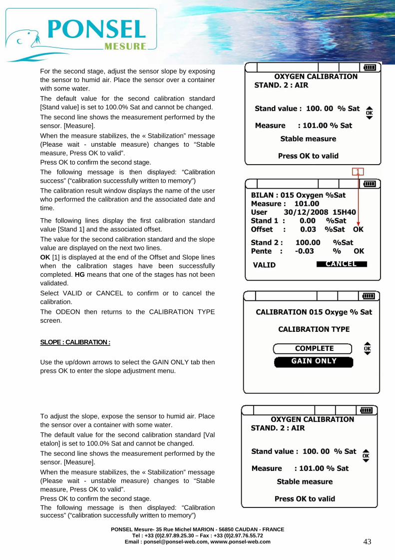
You can calibrate the oxygen sensor in 2 stages, via the full calibration menu, or in 1 stage, by adjusting the slope. Chose the type of calibration you want to use, then press OK.
COMPLETE CALIBRATION: You must first adjust the offset by using a water and sodium sulfite solution (sulfite content <2%) Once the solution is homogenized, place the sensor in the solution. This default calibration standard value is 0.00% and cannot be changed. The second line shows the measurement performed by the sensor. [Measure]. When the measure stabilizes, the « Stabilization” message changes to “Stable measure, Press OK to valid”. Press OK to confirm the first stage. The following message is then displayed: “Calibration success” (“calibration successfully written to memory”) If the first stage has been successfully completed, the ODEON moves to the next calibration stage. A message warns if the calibration process has failed. If you want to quit the calibration process, select NO using the right/left arrows then press OK. The ODEON returns to the CALIBRATION TYPE screen.
If you wish to continue with the calibration process, select YES and press OK.
PONSEL Mesure- 35 Rue Michel MARION - 56850 CAUDAN - FRANCE Tel : +33 (0)2.97.89.25.30 – Fax : +33 (0)2.97.76.55.72
Email : [email protected], wwww.ponsel-web.com
43
For the second stage, adjust the sensor slope by exposing the sensor to humid air. Place the sensor over a container with some water. The default value for the second calibration standard [Stand value] is set to 100.0% Sat and cannot be changed. The second line shows the measurement performed by the sensor. [Measure]. When the measure stabilizes, the « Stabilization” message (Please wait - unstable measure) changes to “Stable measure, Press OK to valid”. Press OK to confirm the second stage. The following message is then displayed: “Calibration success” (“calibration successfully written to memory”) The calibration result window displays the name of the user who performed the calibration and the associated date and time.
The following lines display the first calibration standard value [Stand 1] and the associated offset. The value for the second calibration standard and the slope value are displayed on the next two lines. OK [1] is displayed at the end of the Offset and Slope lines when the calibration stages have been successfully completed. HG means that one of the stages has not been validated. Select VALID or CANCEL to confirm or to cancel the calibration. The ODEON then returns to the CALIBRATION TYPE screen.
SLOPE : CALIBRATION : Use the up/down arrows to select the GAIN ONLY tab then press OK to enter the slope adjustment menu. To adjust the slope, expose the sensor to humid air. Place the sensor over a container with some water. The default value for the second calibration standard [Val etalon] is set to 100.0% Sat and cannot be changed. The second line shows the measurement performed by the sensor. [Measure]. When the measure stabilizes, the « Stabilization” message (Please wait - unstable measure) changes to “Stable measure, Press OK to valid”. Press OK to confirm the second stage. The following message is then displayed: “Calibration success” (“calibration successfully written to memory”)
PONSEL Mesure- 35 Rue Michel MARION - 56850 CAUDAN - FRANCE Tel : +33 (0)2.97.89.25.30 – Fax : +33 (0)2.97.76.55.72
Email : [email protected], wwww.ponsel-web.com
44
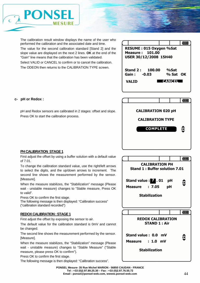
The calibration result window displays the name of the user who performed the calibration and the associated date and time. The value for the second calibration standard [Stand 2] and the slope value are displayed on the next 2 lines. OK at the end of the "Gain" line means that the calibration has been validated. Select VALID or CANCEL to confirm or to cancel the calibration. The ODEON then returns to the CALIBRATION TYPE screen.
c- pH or Redox :
pH and Redox sensors are calibrated in 2 stages: offset and slope. Press OK to start the calibration process.
PH CALIBRATION STAGE 1 First adjust the offset by using a buffer solution with a default value of 7.01. To change the calibration standard value, use the right/left arrows to select the digits, and the up/down arrows to increment. The second line shows the measurement performed by the sensor. [Measure]. When the measure stabilizes, the “Stabilization” message (Please wait - unstable measure) changes to “Stable measure, Press OK to valid”. Press OK to confirm the first stage. The following message is then displayed: “Calibration success” (“calibration standard recorded”)
REDOX CALIBRATION : STAGE 1 First adjust the offset by exposing the sensor to air. The default value for the calibration standard is 0mV and cannot be changed. The second line shows the measurement performed by the sensor. [Measure]. When the measure stabilizes, the “Stabilization” message (Please wait - unstable measure) changes to “Stable Measure” ("Stable measure, please press OK to confirm"). Press OK to confirm the first stage. The following message is then displayed: “Calibration success”.

PONSEL Mesure- 35 Rue Michel MARION - 56850 CAUDAN - FRANCE Tel : +33 (0)2.97.89.25.30 – Fax : +33 (0)2.97.76.55.72
Email : [email protected], wwww.ponsel-web.com
45
If the first stage has been successfully completed, the ODEON moves to the next calibration stage. A message warns if the calibration process has failed. If you want to quit the calibration process, select NO using the right/left arrows then press OK. The ODEON returns to the CALIBRATION TYPE screen. If you wish to continue with the calibration process, select YES and press OK.
PH CALIBRATION STAGE 2 For the second calibration stage, adjust the sensor slope by placing the sensor in a buffer solution with a known pH. The default value for the second calibration standard [Val etalon] is set to 4.01. To change the calibration standard value, use the right/left arrows to select the digits, and the up/down arrows to increment. The second line shows the measurement performed by the sensor. [Measure]. When the measure stabilizes, the «”Stabilization” message (Please wait - unstable measure) changes to “Stable Measure, Press OK to valid” ("Stable measure, please press OK to confirm"). Press OK to confirm the second stage. The following message is then displayed: “Calibration success” (“calibration standard recorded”)
REDOX CALIBRATION STAGE 2 For the second calibration stage, adjust the sensor slope by placing the sensor in a buffer solution with a known Redox potential. The default value for the second calibration standard [Stand value] is set to 240mV. To change the standard value, use the right/left arrows to select the digits, and the up/down arrows to increment. The second line shows the measurement performed by the sensor. [Measure]. When the measure stabilizes, the « Stabilization” message (Please wait - unstable measure) changes to “Measure stable, Press OK to valid” ("Stable measure, please press OK to confirm"). Press OK to confirm the second stage. The following message is then displayed: “Calibration success” (“calibration standard recorded”) The calibration result window displays the name of the user who performed the calibration and the associated date and time. The following lines display the first calibration standard value [Stand 1] and the associated offset. The value for the second calibration standard and the slope value are displayed on the next two lines. OK [1] is displayed at the end of the Offset and Slope lines when the calibration stages have been successfully completed. HG means that one of the stages has not been validated. Select VALID or CANCEL to confirm or to cancel the calibration. The ODEON then returns to the CALIBRATION TYPE screen.

PONSEL Mesure- 35 Rue Michel MARION - 56850 CAUDAN - FRANCE Tel : +33 (0)2.97.89.25.30 – Fax : +33 (0)2.97.76.55.72
Email : [email protected], wwww.ponsel-web.com
46
d- TURBIDITY and CONDUCTIVITY: Sensor calibration is performed in two stages: offset and slope. An additional stage also allows you to calibrate the work range for these 2 parameters. Press OK to start the calibration process. SELECTING THE RANGE Turbidity Calibration: Before entering the calibration menus, you must select the range for the sensor calibration. Use the up/down arrows to select the range then press OK to confirm.
Conductivity calibration: Before entering the calibration menus, you must select the range for the sensor calibration. Use the up/down arrows to select the range then press OK to confirm.
TURBIDITY CALIBRATION: STAGE 1 You first need to adjust the offset with a clear water solution. The value for this first calibration standard is set to 0 NTU. The second line shows the measurement performed by the sensor. [Measure]. When the measure stabilizes, the “Stabilization” message (Please wait - unstable measure) changes to “Stable measure, Press OK to valid”. Press OK to confirm the first stage. The following message is then displayed: “Calibration success” (“calibration standard recorded”)

PONSEL Mesure- 35 Rue Michel MARION - 56850 CAUDAN - FRANCE Tel : +33 (0)2.97.89.25.30 – Fax : +33 (0)2.97.76.55.72
Email : [email protected], wwww.ponsel-web.com
47
CONDUCTIVITY CALIBRATION: STAGE 1 Expose the sensor to the air to perform the first stage of the calibration process. The value for this first calibration standard is set to 0 0 µS/cm. The second line shows the measurement performed by the sensor. [Measure]. When the measure stabilizes, the “Stabilization” message (Please wait - unstable measure) changes to “Stable measure, Press OK to valid”. Press OK to confirm the first stage. The following message is then displayed: “Calibration success” (“calibration standard recorded”)
If the first stage has been successfully completed, the ODEON moves to the next calibration stage. A message warns if the calibration process has failed. If you want to quit the calibration process, select NO using the right/left arrows then press OK. The ODEON returns to the CALIBRATION TYPE screen. If you wish to continue with the calibration process, select YES and press OK. TURBIDITY CALIBRATION: STAGE 2 For the second calibration stage, adjust the sensor slope using a Formazine solution prepared from a 4,000 NTU stock solution. The default value for the second calibration standard [Val etalon] is set to half the selected work range. To change the standard value, use the right/left arrows to select the digits, and the up/down arrows to increment. The second line shows the measurement performed by the sensor. [Measure]. When the measure stabilizes, the “Stabilization” message (Please wait - unstable measure) changes to “Stable measure, Press OK to valid”. Press OK to confirm the second stage. The following message is then displayed: “Calibration success” (“calibration standard recorded”)
Range Calibration standard 2 0.00-50.00 NTU 25.00 NTU 0.0-200.0 NTU 100.0 NTU 0 - 1000 NTU 500 NTU 0 - 4000 NTU 2000 NTU

PONSEL Mesure- 35 Rue Michel MARION - 56850 CAUDAN - FRANCE Tel : +33 (0)2.97.89.25.30 – Fax : +33 (0)2.97.76.55.72
Email : [email protected], wwww.ponsel-web.com
48
CONDUCTIVITY CALIBRATION: STAGE 2 For the second calibration stage, adjust the sensor slope using a buffer solution with a known conductivity. The default value for the second calibration standard [Val etalon] is defined according to the selected work range. To change the calibration standard value, use the right/left arrows to select the digits, and the up/down arrows to increment. The second line shows the measurement performed by the sensor. [Measure]. When the measure stabilizes, the “Stabilization” message (Please wait - unstable measure) changes to “Stable measure, Press OK to valid”. Press OK to confirm the second stage. The following message is then displayed: “Calibration success” (“calibration standard recorded”)
Range Calibration standard 2
0.0 -200.0 µS/cm 84 µS/cm at 25°C 0.0 -2000 µS/cm 1413 µS/cm at 25°C 0.00 - 20.00 mS/cm 12880 µS/cm 0.0 - 200.0 mS/cm 111.8 mS/cm
The calibration result window displays the name of the user who performed the calibration and the associated date and time. The following lines display the first calibration standard value [Stand 1] and the associated offset. The value for the second calibration standard and the slope value are displayed on the next two lines. OK [1] is displayed at the end of the Offset and Slope lines when the calibration stages have been successfully completed. HG means that one of the stages has not been validated. Select VALID or CANCEL to confirm or to cancel the calibration. The ODEON then returns to the CALIBRATION TYPE screen.

PONSEL Mesure- 35 Rue Michel MARION - 56850 CAUDAN - FRANCE Tel : +33 (0)2.97.89.25.30 – Fax : +33 (0)2.97.76.55.72
Email : [email protected], wwww.ponsel-web.com
49
CHAPTER 5 – DATA MANAGEMENT: WinTEK Viewer. The WinTEK application allows you to manage the measurement data saved on the ODEON, on a PC. Once you have installed the application on your PC, you can recover, view and store the data collected via the ODEON.
5.1- ODEON/ PC connection:
Before connecting the ODEON to the PC, make sure the current recording cycle has ended. The data download is likely to malfunction if measurement recording is still ongoing. Connect the active ODEON to the PC with the special USB cable. The PC will display the “New device detected” message once it has detected the ODEON. Use the “Add new hardware" wizard to configure the ODEON with the PC.
Then run the WinTek Viewer :
Select the language (Anglais) at the lower right of the screen. Then in the TOOLS tab select “Raise a logger”
Language selection
Connection to ODEON

PONSEL Mesure- 35 Rue Michel MARION - 56850 CAUDAN - FRANCE Tel : +33 (0)2.97.89.25.30 – Fax : +33 (0)2.97.76.55.72
Email : [email protected], wwww.ponsel-web.com
50
In the « Load logger » window, click on « + » to search for the ODEON currently connected to the PC. The ODEON name is displayed in the horizontal bar, with its serial number. In this example, the ODEON serial number is SN-ODEOA-0051 [2]. Then click on the "Connecter" (Connect") button to activate the ODEON/PC connection [3].
5.2- Selecting the LOCATION
Once the connection has been established, a "Sélection site" (Select site) window is displayed with the different locations recorded for the ODEON. The first column in the table shows the location names and the second column shows the number of recordings [1].
Click right on the « + » to the left of the first column to display the serial number of the sensor(s) connected to the ODEON during the recordings [2]. The data will be downloaded and stored in the STUDY folder you have defined [3]. A STUDY folder may contain several LOCALISATIONs corresponding to different recording campaigns performed in the same context. Click on the « + » button to the right of the horizontal bar and enter your file name in the "New study name" tab. Press “Validate” then click on the small downward arrow to select your file name.
1
23
1
2
3

PONSEL Mesure- 35 Rue Michel MARION - 56850 CAUDAN - FRANCE Tel : +33 (0)2.97.89.25.30 – Fax : +33 (0)2.97.76.55.72
Email : [email protected], wwww.ponsel-web.com
51
5.3- Downloading the data
To recover the data for a location, place the PC’s cursor on the location and click on "Validate" The ODEON displays a new window. Click on "Unload of the date" to recover the measurements recorded for the location [1]. Click on « Download the data» [2] to confirm the download. A progress bar will indicate that the data download is in progress.
Location names button will
synchronize the ODEON and PC date and time
Data download button
1
ODEON serial number
2
Data download button

PONSEL Mesure- 35 Rue Michel MARION - 56850 CAUDAN - FRANCE Tel : +33 (0)2.97.89.25.30 – Fax : +33 (0)2.97.76.55.72
Email : [email protected], wwww.ponsel-web.com
52
5.4- Viewing the data The data exported to the PC can be displayed as graphs, tables or reports. Chose the LOCATION data you want to view in the window on the left of the WinTEK Viewer. Click on « + » to display the POD and all its recordings, then double click on the parameter you want to view. The application will then display the graph, data table and report for that parameter.
In graph display mode, click right and hold on the relevant part, to zoom in on part of the graph. Click left and hold while moving up or down the graph, to move the graph vertically. You can create a cursor to follow a parameter's trends over a given recording period. Click on the button represented by a large blue cross.
« Data » and « Report » display tabs
Graph screen
LOCATION parameters selection
Cursor button
Measurement Information
Blue cross for cursor creation

PONSEL Mesure- 35 Rue Michel MARION - 56850 CAUDAN - FRANCE Tel : +33 (0)2.97.89.25.30 – Fax : +33 (0)2.97.76.55.72
Email : [email protected], wwww.ponsel-web.com
53
5.5- Exporting data to Excel
Click on the « Data » tab, then on the "Export" button, to export data to an Excel spreadsheet. You can export data in the PDF, CSV or XLS format. Click on « xls » to create your file name.
"Exporter" (Export) button

PONSEL Mesure- 35 Rue Michel MARION - 56850 CAUDAN - FRANCE Tel : +33 (0)2.97.89.25.30 – Fax : +33 (0)2.97.76.55.72
Email : [email protected], wwww.ponsel-web.com
54
CHAPTER 6 - SENSORS, ACCESSORIES, CONSUMABLES
6.1 .Sensors :
REFERENCE PONSEL name PON-OPTOD-N3 OPTOD digital sensor with 3 meters of cable. PON-OPTOD-N7 OPTOD digital sensor with 7 meters of cable. PON-OPTOD-N15 OPTOD digital sensor with 15 meters of cable. PONCIR-NTU-N3 NTU digital sensor with 3 meters of cable. PONCIR-NTU-N7 NTU digital sensor with 7 meters of cable. PONCIR-NTU-N15 NTU digital sensor with 15 meters of cable. PONCPC-C4E-N3 Digital conductivity/salinity sensor with 3 meters of cable. PONCPC-C4E-N7 Digital conductivity/salinity sensor with 7 meters of cable. PONCPC-C4E-N15 Digital conductivity/salinity sensor with 15 meters of cable. PONCPC-APHEHT-N3 Adaptor for digital pH/EH/T°C sensor with 3 meters of cable. PONCPC-APHEHT-N7 Adaptor for digital pH/EH/T°C sensor with 7 meters of cable. PONCPC-APHEHT-N15 Adaptor for digital pH/EH/T°C sensor with 15 meters of cable. PONCAR-PHEHT CARTRIDGE FOR PHEHT SENSOR PON-CABN ADDITIONAL CABLE FOR DIGITAL SENSOR
6.2- Accessories.
REFERENCE PONSEL name PONOD-USB USB/PC CABLE PONOD-CAB1 CHARGER CABLE PONOD-CAB2 12V EXTERNAL POWER SUPPLY CABLE PONOD-BATR ODEON RECHARGEABLE BATTERIES OPTION
CHARGER CABLE 4 NiMH rechargeable batteries”
PON-OD-DODISK SPARE DODISK FOR OPTOD SENSOR PONVM2-ODEON BLUE ODEON FIELD CASE PONOD-OPEN OPEN SOFTWARE UPDATE
6.2- Consumables.
REFERENCE PONSEL name PON-NÎMH4 Set of 4 NiMH rechargeable batteries PONPH-AMP-4 125ml bottle of pH 4 buffer solution PONPH-AMP-7 125ml bottle of pH 7 buffer solution PONPH-AMP-10 125ml bottle of pH 10 buffer solution PONPEPNET 125ml bottle of pepsin cleaning solution for EH pH type sensors PONEHSOL470 Redox meter adjustment solution: 470mV at 20°C, 125ml bottle PONEHSOL240 Redox meter adjustment solution: 240mV at 20°C, 125ml bottle PONABNET Abrasive for Redox and Conductivity sensors usable in running water PONO2-ZR Bottle of sodium sulphite: 20g PON-FORMAZ 150ml bottle of formazine, 4,000NTU stock solution PONCSOL-1000 Conductimeter adjustment solution: KCI 1,413mS at 25°C, 125ml bottle PONCSOL-10000 Conductimeter adjustment solution: KCI 12,880mS at 25°C, 125ml
bottle

PONSEL Mesure- 35 Rue Michel MARION - 56850 CAUDAN - FRANCE Tel : +33 (0)2.97.89.25.30 – Fax : +33 (0)2.97.76.55.72
Email : [email protected], wwww.ponsel-web.com
55
Technical support services
PONSEL Mesure 35 Rue Michel MARION – 56850 CAUDAN
Tel.: (33) 2.97.89.25.30 Fax : (33) 2.97.76.55.72 e-mail: [email protected]