oem 230 series drive user guide - parker hannifin · oem 230 series drive user guide ... psu...
TRANSCRIPT

OEM 230 Series DriveUser Guide
For engineering For engineeringassistance in Europe: assistance in the U.S.:Parker Hannifin plc Parker Hannifin CorporationElectromechanical Division - Digiplan Compumotor Division21 Balena Close 5500 Business Park Drive, Suite DPoole, Dorset Rohnert Park, CA 94928England, BH17 7DX USADirect Lines for Technical Support Telephone: (800) 358-9070Tel: 01202-699000 Fax: 01202-695750 Fax: (707) 584-3793E-mail: [email protected] FaxBack System: (800) 936-6939
BBS: (707) 584-4059E-mail: [email protected]
Part No: 1600.170.02 November, 1996

IMPORTANT INFORMATION FOR USERS
Installation and Operation of Digiplan Equipment
It is important that Digiplan motion control equipment is installed and operated in such a way that all applicablesafety requirements are met. It is your responsibility as an installer to ensure that you identify the relevantsafety standards and comply with them; failure to do so may result in damage to equipment and personal injury.In particular, you should study the contents of this user guide carefully before installing or operating theequipment.
Under no circumstances will the suppliers of the equipment be liable for any incidental, consequential or specialdamages of any kind whatsoever, including but not limited to lost profits arising from or in any way connectedwith the use of the equipment or this user guide.
SAFETY WARNING
High-performance motion control equipment is capable of producing rapid movement and very high forces.Unexpected motion may occur especially during the development of controller programs. KEEP WELL CLEARof any machinery driven by stepper or servo motors. Never touch any part of the equipment while it is inoperation.
This product is sold as a motion control component to be installed in a complete system using good engineeringpractice. Care must be taken to ensure that the product is installed and used in a safe manner according tolocal safety laws and regulations.
High voltages exist within enclosed units, on rack system backplanes (motherboards) and on transformerterminals. Keep clear of these areas when power is applied to the equipment.
Ensure the AC power is disconnected before attempting to make any system connections. Never disconnectthe motor with power on; this will damage the drive and the motor contacts.
Do not handle the drive until 8 minutes after removing power to ensure that the capacitors have dischargedunless for the purpose of link changing which may be performed with care as soon as power is removed.
If the equipment is used in any manner that does not conform to the instructions given in this manual , then theprotection provided by the equipment may be impaired.
EMC INFORMATIONEMC Information is presented in boxed paragraphs (such as this one). Information in this User Guide consistsof recommendations only; compliance is not guaranteed. The OEM 230 series of drives are sold as complex
components for use by professional system builders. They are not intended for sale to end users.
The information in this user guide, including any apparatus, methods, techniques, and concepts describedherein, are the proprietary property of Parker Digiplan or its licensors, and may not be copied, disclosed, or usedfor any purpose not expressly authorised by the owner thereof.
Since Digiplan constantly strives to improve all of its products, we reserve the right to modify equipment anduser guides without prior notice. No part of this user guide may be reproduced in any form without the priorconsent of Digiplan.
© Digiplan Division of Parker Hannifin plc, 1996– All Rights Reserved –
Table of Contents
INTRODUCTION ................................................................................... 1SPECIFICATION................................................................................... 3INSTALLATION .................................................................................... 7SETTING UP ........................................................................................ 2 9MAINTENANCE & TROUBLESHOOTING .............................................. 3 3INDEX .................................................................................................. 3 7
User Guide Change Summary
The following is a summary of the primary changes to this userguide since the last version was released. This user guide, version1600.170.02, supersedes version 1600.170.01.
When a user guide is updated, the new or changed text isdifferentiated with a change bar in the outside margin (thisparagraph is an example). If an entire chapter is changed, thechange bar is located on the outside margin of the chapter title.
Major changes introduced at revision 02 are:
LVD Compliance
EMC installation guidelines
Warning symbols used on the OEM 230 series of drives have the following meanings:
Refer to theaccompanying documentation
Risk of electric shock
Hot surface
Protective conductor terminal
Alternating current
Frame or chassis terminal

2

ii OEM SD DRIVES USER GUIDE
CONTENTS iii
Product Type: OEM 230, OEM 330, OEM 530 and OEM 530-D
The above products are in compliance with the requirements of directives
� 73/23/EEC Low Voltage Directive
� 93/68/EEC CE Marking Directive
The OEM 230 Series of drives are sold as complex components to professional assemblers,as components they are not compliant with Electromagnetic Compatibility Directive89/336/EEC. However, information is offered in this User Guide on how to install thesedrives in a manner most likely to minimise the effects of drive emissions and to maximise theimmunity of drives from externally generated interference.

INTRODUCTION 1
INTRODUCTION
ProductDescription
The OEM 230 Series consists of the OEM230, OEM330, OEM530and the OEM530-D drives. OEM 230 Series Drives are high-performance, bipolar, chopper-regulated stepper drives designed foroptimum performance in low and medium power applications. Arecirculating chopper regulator improves operating efficiency,minimizes power consumption and reduces motor and drive heating.They may be powered directly from DC supplies or the secondarywinding of a centre tapped isolating transformer. One transformer,or one DC supply can power several drives in a multi-axis system.Separate logic and motor supply inputs allow you to use up to a60-volt DC motor supply, providing extra torque at high speeds.
The motor current selecting link, mounted on the drive, allows you toconfigure the drive for a wide range of stepper motors.
OEM 230 Series Drives operate rotary stepper motors at resolutionsof either 200 steps/rev (full-step) or 400 steps/rev (half-step), andcan also be used to operate linear stepper motors.
Motor short-circuit protection is assured across and between phases(not phase-to-ground).
The drives are suitable for use with hybrid and permanent magnetstepping motors having 4, 6, or 8 leads.
The drive may be mounted in a rack or by means of the fixing holesprovided.The drives can be used as stand alone units with separate controlinputs and motor connection/power inputs.An on-board clock can be used to control drive motion or an externalstep/direction source can be used.
The step, direction and shutdown inputs are fully opto isolated formaximum noise immunity, but they can be configured as singleended non-isolated inputs.
The system may be configured to allow the step signal to beprovided by the on-board step source. Two separate programmablespeeds are available. These are set by resistors connected to theD-type connector and may be selected remotely, with controlledacceleration and deceleration between the two speeds. When theon-board clock source is used, a controller with access to the ‘clockmonitor’ signal can use the Fast, Slow and Direction inputs to controlmotor movement.

2 OEM SD DRIVES USER GUIDE

SPECIFICATION 3
SPECIFICATION
OEM 230Series Drive
Specifications
Parameter ValueAmplifiers
TypeMotor resolutionProtection
Short circuitNominal output current (two-phase-on)
Maximum stepping rate
Nominal chopping frequency
Bipolar Chopper200 or 400 steps/rev (user-selectable)
Phase-to-phase and across phases (not phase to ground)2A/phase (OEM220), 3A/phase (OEM330), 5A/phase (OEM530)- link reduceable10kHz @ 200 steps /rev (Full step)20kHz @ 400 steps /rev (Half step)18kHz
Command InterfaceSTEP/DIR/SHUTDOWNConfigured as differential opto-isolatedTTL inputs
Drive requirements
Configured as single ended nonisolated 5V signals with active lowinputs
Drive requirementsMaximum current
STEPMinimum pulse width
Drive clocks on transition to state ()
DIRShaft reversal on transition
SHUTDOWNMotor shutdown on transition to state ()
Fault, Clock Monitor
Power up reset time
Drive dimensions
>3.5V high, <0.8V low +5V max.max input current ±15mAmin input current ±6.3mA
intended to be driven open collector>3.5V high, <0.8V low +5V max.15mA
5�sSTEP+(high) STEP-(low)
DIR+, DIR-
SHUTDOWN+(high) SHUTDOWN-(low)
Open-collector NPN transistorsLow (transistor switched to GND) +0.35V max. @ 15mA max.High (transistor off) +30V max.
0.2 - 0.6 secs
Overall 100 x 182 x 35mm (3.9 x 7.2 x 1.4 inches)card 100 x 167mm (3.9 x 6.6 inches)
Table 1. OEM 230 Series Drive Specifications

4 OEM 230 SERIES DRIVE USER GUIDE
OEM 230 SeriesDrive
Specifications(Continued)
AC Power Fed OperationDrive supply voltageSupply frequency rangeLogic supply voltage
Drive power requirementsOEM230OEM330OEM530/530-D
DC Power Fed OperationMotor supplyPSU Continuous current ratings
OEM230OEM330OEM530/530-D
Logic Supply RequirementsCurrent Requirements
Drive onlyWith max auxiliary output load
FusesFS1 (Logic Supply)FS2 (Motor Supply)Fuse type FS1 & FS2Dump fuse
44-0-44VAC ±10% for 60VDC (supply range 18Vrms to 44Vrms)47 to 63Hz18-0-18VAC (+10%, -15%) at 6VA (14VA with max current
drawn from auxiliary DC output)
100VA max150VA max300VA max
24V to 60V DC (70V DC absolute maximum)
1.75A2.5A4.0A24V DC (+10%, -20%)
250mA
550mA
1A3.15A (OEM230), 4A (OEM330), 6.3A (OEM530)Quick-acting, low breaking capacity, 5 x 20mm500mA TL LB, 5 x 20mm (for OEM 530-D)
Internal Clock SourceSpeed range
FastSlowFactory preset acceleration timeFactory preset deceleration time
600 - 20,000 steps/sec (ramped)30 - 1,000 steps/sec (not ramped)60 ms30 ms
PowerAuxiliary output load
Transformer rating
24VDC nominal 300mA maximum
TO193 - 300VATO194 - 600VA
OutputCurrent range
OEM230OEM330OEM530/530-D
Tolerance of current level
300mA - 3.0A900mA - 4.5A1.5A - 7.5A±10%
MotorsTypeNumber of leadsInductance rangePower/Motor connection
2-Phase hybrid or permanent magnet (normally 1.8°)4, 6, or 8 (5 lead not suitable)0.7mH-30mHrefer to section in the manual

SPECIFICATION 5
Table 1. OEM 230 Series Drive Specifications (Continued)
Pin Name I/O
Min. onState
Current
Max.Current
Max.Voltage
SignalLevels
Comments
1 Step + I ±6.3mA ±15mA 5V TTL note 1, 32 Direction + I ±6.3mA ±15mA 5V TTL note 1, 23 On Board
ClockMonitor
O 15mA(at 0.35V)
30V Opencollector30V max
Active low
4 Slow Adjust I ------- 20mA 12V -------5 Fault O ------- 15mA
(at 0.35V)30V Open
collector30V max.
Active high
6 Slow I ------- 1.5mA 12VLow <0.8V
High =OpenCircuit
Active low
7 Fast I ------- 1.5mA 12VLow <0.8V
High =OpenCircuit
Active low
8 AdjustCommon
O ------- 20mA 12V ------- ---
9 Step - I ±6.3mA ±15mA 5V TTL note 1, 310 Direction - I ±6.3mA ±15mA 5V TTL note 1, 211 Shutdown + I ±6.3mA ±15mA 5V TTL note 112 Shutdown - I ±6.3mA ±15mA 5V TTL note 113 0V I/
O14 Fast Adjust I ------- 20mA 12V -------15 24V AUX
output300mA 26.4V max
(16V min)
Table 2. Control I/O Signal
note 1 For single ended control make solder connection at link pads on reverse of drive.Drive ‘(-) inputs’ from open collector transistor, ON state <0.8V, OFF state max5V, leave ‘(+) inputs’ open circuit.
note 2 Do not change state of ‘DIRECTION+’ and ‘DIRECTION-’ inputs within 5�s ofSTEP transition to STEP+ high, STEP- low.
note 3 Minimum pulse width is 5�s

INSTALLATION 7
INSTALLATION
InstallationRequirements
OEM 230 Series drives must be installed by competent personnelfamiliar with the the installation, commissioning and operation ofmotion control equipment. In the final application the equipmentmust be enclosed to prevent the operator coming into contact withany high voltages. This includes the transformer, drive and motorterminations.
The OEM 230 Series of drives are not EMC compliant, they are soldas a complex component for use by professional assemblers ofmotion control systems. Where a system is not required to conformwith the European EMC directive the installation proceduredescribed in this section may be followed. Systems which are toconform to the European EMC directive should be assembled usingthese procedures and additionally the EMC specific installationrecommendations, described at the end of this Section. Digiplancannot guarantee EMC compliance.
In the final application, the equipment must be enclosed to preventoperator access to everything other than signal I/O connector SKT2.Metal equipment cabinets offer the most advantages for siting theequipment since they can provide operator protection, EMCscreening and can be readily fitted with interlocks arranged toremove all AC power when the cabinet door is opened. This form ofinstallation also allows the fitting of metal trays beneath theequipment to act as a flame barrier, which must be provided in thefinal installation, in accordance with LVD requirements.
PowerConnections
The layout and pin numbering of drive edge connectors is shown inFigure 1. The 15-way D-type socket, SKT2 is used for all the drivecontrol functions and is compatible with Compumotor indexerconnections.The signal function of each pin is described in Indexer Connections.
SKT1SKT2
PIN 1PIN 10PIN 1PIN 8
PIN 15 PIN 9
Figure 1. Drive Connector Pin Numbering

8 OEM 230 SERIES DRIVE USER GUIDE
The insulation ratings for power connections (SKT1) should be atleast 350V where the insulation is between power and signal wiring.A higher insulation rating will be required for the mains wiring.
Transformer wiring needs to be at least 1mm2 in area and theprimary wiring should be routed well away from the secondary wiringand signal wiring. Note: the drive 0V connection must be earthed.
A disconnect device must be provided which isolates all mainssupply current-carrying conductors. If the mains supply ispermanently connected, a switch or circuit breaker must be includedin the wiring. It must be placed close to the equipment (less than 1metre) and marked as the disconnecting device for the equipment.
SKT1 KeyingPegs
Connector SKT1 is used for both motor connections (Pins 1-5) andpower connections (Pins 6-10). The connector is fitted with keyingpegs to prevent the cross-connection of Motor and Power plugs. The position of the keying pegs is illustrated in Figure 2.
MOTOR PLUG
POWER PLUG
3 - GND
2 - B+
4 - A-
5 - A+
6 - 44
7 - 18
8 - 0V
9 - 18
PIN 1 - B-
PIN 10 - 44
Figure 2. SKT1 Keying Peg Layout
Wiring Guidelines Proper grounding of electrical equipment is essential to ensure thesafety of personnel. You can reduce the effects of electrical noisedue to electromagnetic interference (EMI) by grounding. All Digiplanequipment should be properly grounded.In general, all components and enclosures must be connected toearth ground to provide a low impedance path for ground fault ornoise-induced currents. All earth ground connections must becontinuous and permanent. Digiplan recommends using a centralearth stud e.g. mounted on a rack end-plate or close to it. ACground, the transformer shield, the power plug 0V terminal and theenclosure metalwork should all be connected to this stud. Inparticular, you should connect any 0V bus with an 18AWG (1mm2)cable kept as short as possible.

INSTALLATION 9
The motor ground connection should be connected to the motorcable shield at the drive end only. To avoid ground loops, the motorcable shield should not be connected to the motor casing.
TransformerConnections
As illustrated in Figure 3, the transformer leads are connected to the5-way boxed power connector which plugs into part of SKT1. Thepower connector is fitted with keying pegs to prevent it beinginserted in the motor connection part of SKT1. Details of theposition of keying pegs are given in Figure 2.
44
18
0
18
44
To next axis if present
Figure 3. Secondary Transformer Connections
Where the transformer rating is adequate, the same secondary canbe used to power multiple axes as shown in Figure 3.

10 OEM 230 SERIES DRIVE USER GUIDE
TransformerWiring
Depending on your application, the OEM 230 Series Drive can bepowered with either the TO193 or TO194 transformer. If analternative transformer is used, it must have an earthed screenbetween primary and secondary. The insulation rating betweenprimary and secondary must also be adequate, a minimum of 2300VAC RMS is recommended.
Figure 4 Primary Supply Transformer Wiring
Be sure to connect the AC ground (GND) and SCN (EarthGround) to the safety earth.
Line Fuses Line fuses need to be added to protect the transformer andassociated wiring. If the live wire cannot be readily identified. fuseboth phase conductors. The value of fuse required is given by:
1.5 �VAsupply volts
in amps
Fuse types should be anti-surge HBC. Recommended values are:
For TO193 (300VA) 3.15A TL HBCFor TO194 (600VA) 5.0A TL HBC
InputVoltage
Connect ACLine to:
Connect ACNeutral to:
ConnectStuds:
110 B C B&E; C&F120 A C A&D; C&F220 B F C&E230 A F C&E240 A F C&D
INSTALLATION 11
Table 3. Transformer Primary Connections
WARNING - danger of electric shock
Do not connect the transformer to the drive while power is applied to the transformer.Do not touch the wiring studs on the transformer after it is plugged into an AC outlet.
This can be fatal.Always wire the transformer first, then check the secondary output voltages on open-circuit BEFORE you connect the transformer to the Drive. Note: Be sure to connect
the AC ground (GND) to SCN (Earth Ground).
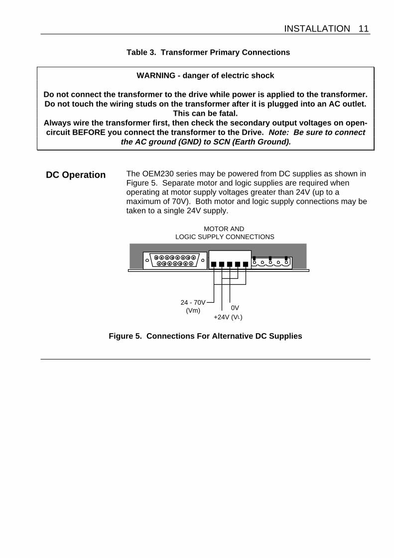
DC Operation The OEM230 series may be powered from DC supplies as shown inFigure 5. Separate motor and logic supplies are required whenoperating at motor supply voltages greater than 24V (up to amaximum of 70V). Both motor and logic supply connections may betaken to a single 24V supply.
24 - 70V (Vm)
+24V (VL)0V
MOTOR AND LOGIC SUPPLY CONNECTIONS
Figure 5. Connections For Alternative DC Supplies

12 OEM 230 SERIES DRIVE USER GUIDE
MotorSelection
Usually optimum performance will be obtained when the currentrating of the motor is between 1 and 1.5 times the drive rating (referto specification).For maximum high speed torque a motor rating of 7.5A should beused with the OEM530, 4.5A with the OEM330 and 3.0A with theOEM230. The drives can be derated to accommodate motors withlower current ratings however, the high speed torque will bereduced.Do not use a drive setting which gives an output current greater thanthe motor rating.With 4 lead motors the bipolar rating is quoted and this should matchthe criteria stated above.With 6 lead motors the unipolar rating is quoted, but for bestperformance with the OEM Drives the centre tap of each windingshould be left unconnected and the connections made between thewinding ends. This will give a bipolar rating 70% of the quoted motorunipolar rating. So a motor unipolar rating of 3.0A should be usedwith the OEM230.With 8 lead motors the bipolar rating of the motor, which is normallyquoted, refers to a parallel winding connection. With the windingsconnected in series the current rating of the motor connection will be50% that of the bipolar rating, and the motor will give improved low-speed torque, but reduced high-speed torque.

INSTALLATION 13
Torque speed data for SM series stepper motors
Speed, revs per sec Speed, revs per sec Speed, revs per sec
Speed, revs per sec Speed, revs per sec Speed, revs per sec
Speed, revs per sec Speed, revs per sec Speed, revs per sec
oz-inNm Nmoz-in oz-inNm
oz-inNm Nmoz-in oz-inNm
oz-inNm Nmoz-in oz-inNm
SM57–51 Motor
SM57–83 Motor
SM57–102 Motor
OEM230: 60v 2A OEM330: 60v 3A OEM530: 60v 5A
Parallel connection Series connection
SM83–62 Motor SM83–135 Motor
SM83–62 MotorSM57–83 Motor
SM83–93 MotorSM57–102 Motor
14 OEM 230 SERIES DRIVE USER GUIDE
Long Motor Leads Using a motor with long leads will cause the cabling resistance tobecome significant when compared to the resistance of the motor.The DC volt drop of the cable and motor connection, whenmeasured at the drive, should not exceed 5 volts in order to limitpower dissipation in the drive and maintain maximum systemperformance.
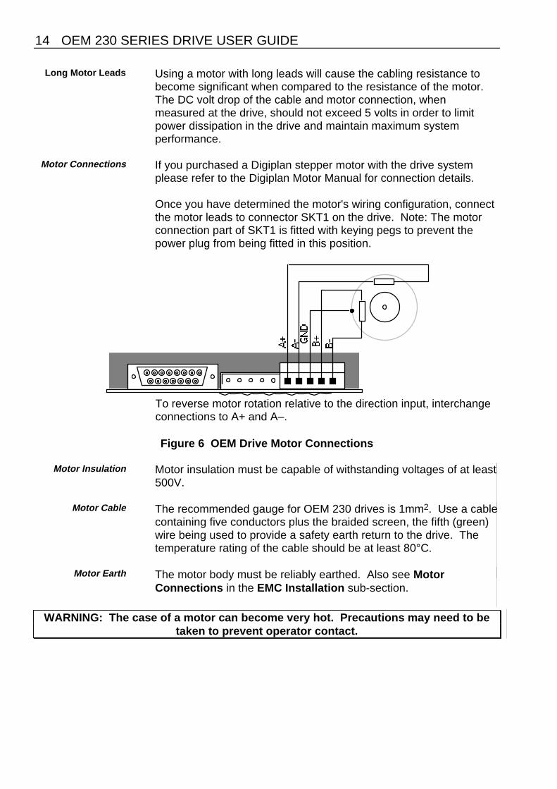
Motor Connections If you purchased a Digiplan stepper motor with the drive systemplease refer to the Digiplan Motor Manual for connection details.
Once you have determined the motor's wiring configuration, connectthe motor leads to connector SKT1 on the drive. Note: The motorconnection part of SKT1 is fitted with keying pegs to prevent thepower plug from being fitted in this position.
To reverse motor rotation relative to the direction input, interchangeconnections to A+ and A–.
Figure 6 OEM Drive Motor Connections
Motor Insulation Motor insulation must be capable of withstanding voltages of at least500V.
Motor Cable The recommended gauge for OEM 230 drives is 1mm2. Use a cablecontaining five conductors plus the braided screen, the fifth (green)wire being used to provide a safety earth return to the drive. Thetemperature rating of the cable should be at least 80°C.
Motor Earth The motor body must be reliably earthed. Also see Motor
Connections in the EMC Installation sub-section.
WARNING: The case of a motor can become very hot. Precautions may need to betaken to prevent operator contact.
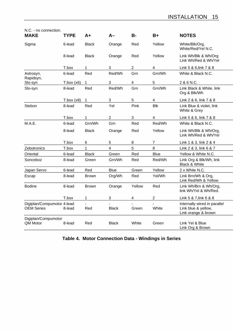
INSTALLATION 15
N.C. - no connection.MAKE TYPE A+ A– B- B+ NOTES
Sigma 6-lead Black Orange Red Yellow White/Blk/Org,White/Red/Yel N.C.
8-lead Black Orange Red Yellow Link Wh/Blk & Wh/OrgLink Wh/Red & Wh/Yel
T.box 1 3 2 4 Link 5 & 6,link 7 & 8
Astrosyn, 6-lead Red Red/Wh Grn Grn/Wh White & Black N.C.Rapidsyn,Slo-syn T.box (x6) 1 3 4 5 2 & 6 N.C.
Slo-syn 8-lead Red Red/Wh Grn Grn/Wh Link Black & White, linkOrg & Blk/Wh
T.box (x8) 1 3 5 4 Link 2 & 6, link 7 & 8
Stebon 8-lead Red Yel Pink Blk Link Blue & violet, linkWhite & Grey
T.box 1 2 3 4 Link 5 & 6, link 7 & 8
M.A.E. 6-lead Grn/Wh Grn Red Red/Wh White & Black N.C.
8-lead Black Orange Red Yellow Link Wh/Blk & Wh/Org, Link Wh/Red & Wh/Yel
T.box 6 5 8 7 Link 1 & 3, link 2 & 4
Zebotronics T.box 1 4 5 8 Link 2 & 3, link 6 & 7
Oriental 6-lead Black Green Red Blue Yellow & White N.C.
Sonceboz 8-lead Green Grn/Wh Red Red/Wh Link Org & Blk/Wh, linkBlack & White
Japan Servo 6-lead Red Blue Green Yellow 2 x White N.C.
Escap 8-lead Brown Org/Wh Red Yel/Wh Link Brn/Wh & Org,Link Red/Wh & Yellow.
Bodine 8-lead Brown Orange Yellow Red Link Wh/Brn & Wh/Org,link Wh/Yel & Wh/Red.
T.box 1 3 4 2 Link 5 & 7,link 6 & 8
Digiplan/Compumotor 4-lead - - - - Internally wired in parallelOEM Series 8-lead Red Black Green White Link blue & yellow,
Link orange & brown
Digiplan/CompumotorQM Motor 8-lead Red Black White Green Link Yel & Blue
Link Org & Brown
Table 4. Motor Connection Data - Windings in Series

16 OEM 230 SERIES DRIVE USER GUIDE
For 6-lead motors, connections shown are for one half-winding.N.C. - no connection.MAKE TYPE A+ A– B- B+ NOTES
Sigma 6-lead Black Wh/Blk/ Red Wh/Red/ Or & Yellow N.C.Orange Yellow
8-lead Black & Or & Red/ Yel &Wh/Or Wh/Blk Wh/Yel Wh/Red
T.box 1 & 5 3 & 6 2 & 7 4 & 8
Astrosyn, 6-lead Red Black Green White Red/Wh &Rapidsyn, Grn/Wh N.C.Slo-syn
T.box(x6) 1 6 4 2 3 & 5 N.C.
Slo-syn 8-lead Red & Blk & Grn & Org &White Red/Wh Blk/Wh Grn/Wh
T.box(x8) 1 & 2 3 & 6 4 & 7 5 & 8
Stebon 8-lead Rd & Yel & Wh & Black &Blue Violet Pink Grey
T.box 1 & 6 2 & 5 3 & 8 4 & 7
M.A.E. 6-lead Grn/Wh White Red Black Grn & Red N.C
8-lead Black & Or & Red & Yel &Wh/Or Wh/Blk Wh/Yel Wh/Red
T.box 3 & 6 1 & 5 4 & 8 2 & 7
Zebotronics T.box 1 & 2 3 & 4 5 & 6 7 & 8
Oriental 6-lead Black Yellow Red White Grn & Blue N.C.
Sonceboz 8-lead Grn & Or & Red & Blk &Blk/Wh Grn/Wh White Red/Wh
Japan Servo 6-lead Red White* Green White*
Escap 8-lead Brn & Brn/Wh & Red & Red/Wh &Orange Org/Wh Yellow Yel/Wh
Bodine 8-lead Brn & Wh/Brn & Yel & Wh/Yel &Wh/Or Orange Wh/Red Red
T.box 1 & 7 3 & 5 4 & 6 2 & 8
Digiplan/Compumotor 4-lead Red Black Green WhiteOEM Series 8-lead Red & Yellow & Green & Brown &
Blue Black Orange White
Digiplan/CompumotorQM Motor 8-lead Red & Blue Blk & Yellow Wh & Brn Green & Org.
* Use correct White for each phase.
Table 5. Motor Connection Data - Windings in Parallel

INSTALLATION 17
SignalConnections
Step + Pin 1& Step- Pin 9
A pulse on these inputs causes the motor to advance on the leadingedge of the pulse (see Figure 7). The pulse should be at least 5µslong. Consult your indexer user guide for instructions on how tochange the output pulse width.The Step inputs are configured as TTL opto-isolated inputs, but canbe configured as non-isolated single ended inputs.
pin 1 (STEP+)
pin 9 (STEP-)
5�s min
Drive steps on this edge
pin 1 (STEP+)
DIR+ >5�s
Figure 7. STEP Timing Diagram
Direction+ Pin 2& Direction- Pin 10
These inputs (pins 2 and 10) control the direction of the motor shaftrotation. Changing the level of these inputs changes the direction inwhich the shaft moves. The logic level at this input needs to bestable within 5µs of the leading edge of the step pulse [transition toSTEP+ (high) STEP- (low)].The Direction inputs are configured as TTL opto-isolated inputs, butcan be configured as non-isolated single ended inputs.
Clock Monitor(Pin 3)
This open collector output allows the on-board clock source to bemonitored externally. The output should be externally pulled upthrough a suitable resistor. The drive steps on the falling edge of thesignal which consists of a low going pulse having a width between 5and 8µs. This output can also be used to monitor an opto-isolatedclock source driving the board.
Slow Rate Adjust(Pin 4)
An external 100K� variable resistor or a fixed resistor may beconnected between this terminal and "Rate Common" (pin 8) tocontrol the slow speed of the internal clock source.The highest speed will be obtained with zero resistance.

18 OEM 230 SERIES DRIVE USER GUIDE
Fault(Pin 5)
This is an output signal which goes high in the event of an overloadfault. It is driven by an open-collector transistor and should bepulled up by an external resistor when the signal is required. Theresistor should be returned to a voltage no higher than +30V, andshould not allow more than 15mA to flow when the output is low.
When a fault occurs, the drive will de-energise. Once the fault hasbeen cleared the drive may be re-energised by either cycling theShutdown signal or by cycling the power to the drive. The Faultoutput will return low as soon as the drive is shut down.
You can establish a visual fault verification by installing an LED asillustrated in Figure 8. Here the LED will be lit unless there is a fault.
+24V
2k2OEM Drive
Fault (pin 5)
(pin 15)
GND (pin 13)
Figure 8. Fault Output Example
Slow (Pin 6) Connect this input to GND directly or through an open collectortransistor to run the internal clock source at the slow rate.
Fast (Pin 7) Connect this input to GND directly or through an open collectortransistor to run the internal clock source at the fast rate.
Rate Common(Pin 8)
Common return connection for external speed controls.
Shutdown+ Pin 11& Shutdown- Pin 12
These differential inputs (pins 11 and 12) are used to energise andde-energise (shutdown) the motor. When the shutdown+ input istaken high and shutdown- is low, the drive is shut down and themotor shaft may be rotated slowly by hand.
NOTE: Back-driving the motor at excessive speed may damage thedrive.
Cycling the shutdown input resets a fault condition, provided thecause of the fault has been removed.
GND(Pin13)
Control signal return.

INSTALLATION 19
Fast Rate Adjust(Pin 14)
An external 10K� variable or fixed resistor may be connectedbetween this terminal and "Rate Common" (pin 8) to control the fastspeed of the internal clock source. The highest speed will beobtained with zero resistance.
+24VDC Out(Pin 15)
This output is used to supply up to 300mA to an external controlmodule such as an indexer card.
Optional AdvanceRate Pot and Switch
Connections
Figure 9 shows typical external connections required when using theinternal clock source.
Slow
Fast
Slow
Fast
100K�
10K�
Direction +
Shutdown +
+24V AUX.
GND
2K2
2K2
Figure 9. Signal Connections
Input Circuits The Step, Direction and Shutdown inputs are configured asdifferential TTL opto-isolated inputs with reverse polarity protection.Details of the input circuits are shown in Figure 10. The Step andDirection input circuits are identical.
47R220R
100pf
LINK PADS
+
-
+5V
330R+
-
+5V
LINK PADS
SHUTDOWNSTEP & DIRECTION
BAS16
HCPL2631HCPL2631
BAS16
Figure 10. Drive Input Circuits

20 OEM 230 SERIES DRIVE USER GUIDE
Single Ended InputConfiguration
Any of the three differential TTL opto-isolated inputs can beconverted to single ended non opto-isolated inputs by making theon-board solder link. Figure 11 shows the required circuitconfiguration when single ended operation is selected. Ensure thatthe external connection is made to the appropriate negative (-) input.
+5V
+
-
GNDGND
Figure 11 Single Ended Input Circuit Configuration
Input Circuit Links The links pads (STEP, SHUT and DIR) are located on the undersideof the OEM Drive board, as shown in Figure 12. Links are made byshorting the appropriate solder pads using tinned copper wire.When you add or remove links, take care to avoid solder splashes ordamage to the drive.
Before connecting any of the links remove all power from the drive and observe antistatic handling precautions.
SKT1
SKT2
SIDE A
DIR
SH
UT
ST
EP
LINK POSITION INFORMATION
Figure 12 Position of Solder Pad Links

INSTALLATION 21
22 OEM 230 SERIES DRIVE USER GUIDE
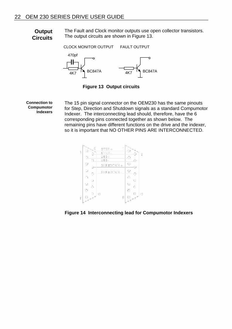
OutputCircuits
The Fault and Clock monitor outputs use open collector transistors.The output circuits are shown in Figure 13.
CLOCK MONITOR OUTPUT
4K7
470pf
BC847A 4K7 BC847A
FAULT OUTPUT
Figure 13 Output circuits
Connection toCompumotor
Indexers
The 15 pin signal connector on the OEM230 has the same pinoutsfor Step, Direction and Shutdown signals as a standard CompumotorIndexer. The interconnecting lead should, therefore, have the 6corresponding pins connected together as shown below. Theremaining pins have different functions on the drive and the indexer,so it is important that NO OTHER PINS ARE INTERCONNECTED.
Figure 14 Interconnecting lead for Compumotor Indexers

INSTALLATION 23
Mechanical /Environmental
EnclosureConsiderations
You should install the drive system in an enclosure to protect itagainst atmospheric contaminants such as oil, moisture, dirt and toprevent operator access. In the USA, the National ElectricalManufacturers Association (NEMA) has established standards thatdefine the degree of protection that electrical enclosures provide.The enclosure should conform to NEMA Type 12 standards if theintended environment is industrial and contains airbornecontaminants. Proper layout of components is required to ensuresufficient cooling of equipment within the enclosure.
EnvironmentalSpecifications
Digiplan recommends you operate your OEM 230 Series Drivesystem under the following conditions:
• Operating Temperature: 0° to 50°C (32° to 122°F)• Relative Humidity: 0% to 95% (non-condensing)• Storage Temperature: -40° to 85°C (-40° to 185°F)
The drive board must be mounted either horizontally with thecomponents uppermost or vertically. Do not use inverted verticalmounting i.e., with the links at the top of the board.
The mains input to the isolating transformer is InstallationCategory III maximum.
The OEM 230 Series of drives can be used in a Pollution Degree 2environment i.e., one in which only non-conductive pollution occurs.
In exceptional circumstances, such as running the motorcontinuously in full-step mode and at maximum current, forced-aircooling may be needed to maintain the local ambient temperaturewithin specification.
InstallationConsiderations
The drive may be installed in a conventional card guide provided thesystem mounting instructions are observed. Standard card clampsmay be used to retain the drive within a rack.
For mounting outside of a rack four holes are provided for the driveto be supported by PCB spacers or pillars. Hole dimensions are for4-40 UNF or M3 clearance (3.4mm).
Only insulating pillars and fixings must be used (e.g., nylon) with amaximum AF dimension of 6.35mm (0.25 inch).
24 OEM 230 SERIES DRIVE USER GUIDE
A B C D E F G H J K
OPT2
OPT1
FS1
FS2
IDENTIFICATION DATE CODE
SKT1
SKT2
LK1+ ++
152mm (5.98in)
5.7mm (0.22in)
5.7mm (0.22in)
LK2 LK3
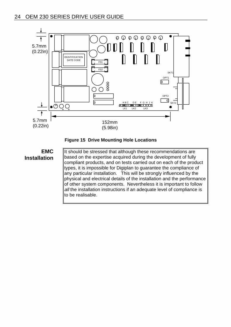
Figure 15 Drive Mounting Hole Locations
EMCInstallation
It should be stressed that although these recommendations arebased on the expertise acquired during the development of fullycompliant products, and on tests carried out on each of the producttypes, it is impossible for Digiplan to guarantee the compliance ofany particular installation. This will be strongly influenced by thephysical and electrical details of the installation and the performanceof other system components. Nevertheless it is important to followall the installation instructions if an adequate level of compliance isto be realisable.

INSTALLATION 25
External enclosures The measures described in these recommendations are primarily forthe purpose of controlling mains conducted emissions. To controlradiated emissions, all OEM drives and rack systems must beinstalled in a steel equipment cabinet which gives adequatescreening against radiated emissions. This external enclosure isalso required for safety reasons. With the exception of drive frontpanels in rack-based units, there must be no user access while theequipment is operating. This is usually achieved by fitting an isolatorswitch to the door assembly. Drives and filters must be in electricalcontact with the panel to which they are mounted. If the panel has apaint finish, it will be necsssary to remove the paint in certain areaswhere required.
To achieve adequate screening of radiated emissions, all panels ofthe enclosure must be bonded to a central earth point. Theenclosure may also contain other equipment such as motioncontrollers, and the EMC requirements of these must be consideredduring installation. Always ensure that drives and rack systems aremounted in such a way that there is adequate ventilation.
It is not necessary to fit front panels to the drives if the rack systemis wholly contained within the enclosure. However, if a 19” case isused with no door or cover in front of the rack, then drive frontpanels must be fitted.
EquipmentRacks
The OEM230 Series of drives may be mounted within a rack system.
For EMC-compliant installation, the rack system can be fitted with anearth bonding strip running across the back of the rack (see Figure16). This is for the bonding of screened motor leads and transformerfeed leads to the rack system. The rack metalwork is also earth-bonded to this tie bar.Note: the earth/grounding strip may be mounted either above orbelow the rack to permit easy removal of the drives.

26 OEM 230 SERIES DRIVE USER GUIDE
Figure 16. Rack EMC Wiring
Filtering theAC mains
supply
A filter must be installed between the incoming AC supply and themains transformer. A suitable filter is Ducati S-221-16. Mount thefilter within 50mm of the transformer as shown in Figure 17. Ensurethat there is no paint on the mounting panel under the filter mountinglugs - it is vital that there is good large-area contact between thefilter and the panel.
Connect the incoming AC supply cable to the push-on terminals onthe filter, with the earth lead connected to a local earth stud or busbar. Route the supply cable so that it runs close to the walls of theenclosure. Connect the filter output terminals to the transformerprimary, keeping the leads twisted together and as short as possible.Take an earth connection from the stud to the SCN terminal on thetransformer, and run this lead close to the AC supply leads (seeFigure 17).
5-core 1mm2 screened cable (with a braided screen) should be usedbetween the transformer and the rack (looking at the back of therack). Use a green wire for the 0V connection. At the transformerend run the cable back towards the mounting panel, expose a shortlength of the screen and anchor the cable close to the filter with a P-clip. When routing this cable to the rack, keep it away from the inputcable to the filter.

INSTALLATION 27
Figure 17. Rack Transformer Wiring
At the rack end, fit a ferrite absorber over the cable and connect theappropriate wires to the Vm and 18V AC terminals on the drive. Fitthe earth bonding strip to the rack end plates. When fitting thebonding strip, use spring washers underneath the nuts and tightensecurely - this is to ensure continuity between the bonding strip andthe rack metalwork. Reconnect the earth wire from the firstmotherboard to the stud on the earth bonding strip.
Route the transformer cable over the earth bonding strip and identifythe location of the mounting point for the P-clip (refer to Figure 16).Expose approximately 12mm of the braided screen at this point andanchor the cable to the bonding strip. Locate the absorber 15-25mmfrom the P-clip using heat-shrink sleeving. Connect the green 0Vwire from the transformer to the stud on the bonding strip, togetherwith a 2.5mm2 green/yellow safety earth wire. Run this wirealongside the screened transformer cable back to the earth studbeside the transformer.
If the OEM230 Series drive is used on its own, mounted on a panel,follow the same installation for the transformer and mains filter.Ensure that the panel on which the drive is mounted is earthed.Take the motor earth connection to a stud on the panel as well asinto the GND terminalin the motor connector. The 0V wire of thetransformer secondary may be earthed at the transformer instead ofthe drive.

28 OEM 230 SERIES DRIVE USER GUIDE
MotorConnections
The recommended gauge for OEM drives is 1mm2. Use a cablecontaining five conductors plus the braided screen, the fifth (green)wire being used to provide a safety earth return to the drive andshould also be connected to the earth bonding strip on the back ofthe rack to avoid breaking the safety earth connection when thedrive board is removed from the rack.Termination at the motor must be made using a 360° bond to themotor body, and this may be achieved by using a suitable clamp.Many stepper motors are designed to accommodate an appropriateconductive terminal gland which can be used for this purpose.
At the rack end, prepare the end of the cable as shown in Figure 18and fit a ferrite absorber. Anchor the cable screen to the earth tiebar using the P-clip behind the corresponding drive. Connect thefour wires from the motor windings to the appropriate terminals onthe motor connector. Attach the green (earth) wire to the tie baradjacent to the P-clip holding the braided screen using a ringterminal.
If the motor cable is more than 4 metres long, a separate safetyearth connection will be required since the impedance of the 1mm2
wire inside the screened cable will be too high. Use a 2.5mm2 cableconnected to the motor body and terminate it on the tie bar next tothe P-clip for that axis. Run this cable close to the screened cablefrom the motor. If there is no suitable termination point on the motorbody, remove the paint from the area of one of the mounting boltsand use an appropriate ring terminal.
Figure 18. Motor Cable Preparation (Drive End

INSTALLATION 29
Control signalwiring
To ensure adequate immunity it is necessary for control circuitsleaving the enclosure to be adequately screened, with the screen ofthe cable bonded back to the tie bar on the rack. Cable with abraided screen should be used, not metallised foil, and shouldconsist preferably of twisted pairs to minimise magnetic coupling. Itis strongly recommended to use opto-isolated drive motherboardswhere the controller is mounted outside the main enclosure.
Where screened leads are used in control circuits that are only opto-isolated at one end, the screen must be referenced to earth at thenon-isolated end. When using a rack with non-opto-isolatedmotherboards, bond the screen to the earth tie bar close to thecorresponding drive.
Ferrite absorberspecifications
The absorbers described in these installation instructions are madefrom a low-grade ferrite material which has high losses at radiofrequencies. They therefore act like a high impedance in thiswaveband.
The recommended components are produced by Parker Chomericsand are suitable for use with cable having an outside diameter up to10mm. The specification is as follows:
Chomerics part number H8FE-1115-NCOutside diameter 17.5mmInside diameter 10.7mmLength 28.5mmImpedance at 25MHz 80•Impedance at 100MHz 120•Curie temperature 130°C (the device should not be operated near this temperature)
Handling andinstalling the ferrite
absorbers
Take care when handling the absorbers - they can shatter ifdropped on a hard surface. For this reason the suggested methodof installation is to use a short length of 19mm diameter heat-shrinksleeving. This gives a degree of physical protection while the cableis being installed. The sleeving should have a shrink ratio of at least2.5:1. Cable ties may be used as an alternative, however they giveno physical protection to the absorber.
SETTING UP 31
SETTING UP
Setting Up Take care, unexpected motion may occur at any time, especiallyduring the commissioning of motion control equipment.
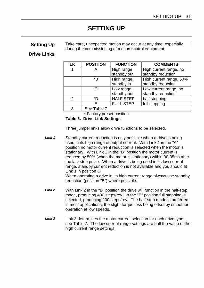
Drive Links
LK POSITION FUNCTION COMMENTS1 A High range
standby outHigh current range, nostandby reduction
*B High range,standby in
High current range, 50%standby reduction
C Low range,standby out
Low current range, nostandby reduction
2 *D HALF STEP half steppingE FULL STEP full stepping
3 See Table 7* Factory preset position
Table 6. Drive Link Settings
Three jumper links allow drive functions to be selected.
Link 1 Standby current reduction is only possible when a drive is beingused in its high range of output current. With Link 1 in the "A"position no motor current reduction is selected when the motor isstationary. With Link 1 in the "B" position the motor current isreduced by 50% (when the motor is stationary) within 30-35ms afterthe last step pulse. When a drive is being used in its low currentrange, standby current reduction is not available and you should fitLink 1 in position C.When operating a drive in its high current range always use standbyreduction (position "B") where possible.
Link 2 With Link 2 in the "D" position the drive will function in the half-stepmode, producing 400 steps/rev. In the "E" position full stepping isselected, producing 200 steps/rev. The half-step mode is preferredin most applications, the slight torque loss being offset by smootheroperation at low speeds.
Link 3 Link 3 determines the motor current selection for each drive type,
see Table 7. The low current range settings are half the value of thehigh current range settings.

32 OEM 230 SERIES DRIVE USER GUIDE
Link 1 Link 3 Motor Current (Amps)position position OEM530 OEM330 OEM230
B* F 5.0 3.0 2.0B* G 4.5 2.7 1.6B* H 4.0 2.4 1.2B* J 3.5 2.1 0.9B* K 3.0 1.8 0.6C F 2.5 1.5 1.0C G 2.25 1.35 0.8C H 2.0 1.2 0.6C J 1.75 1.05 0.45C K 1.5 0.9 0.3
Table 7. Current Range Settings
*Note: use position A instead of position B to inhibit the automatic50% current reduction at standstill. This will maintain full holdingtorque at standstill, but will increase motor and drive heating. Theautomatic standby function is not available with Link 1 in position C.
Figure 19. OEM 230 Series Drive Link Locations
A B C D E F G H J K
OPT2
OPT1
FS1
FS2
IDENTIFICATION DATE CODE
SKT1
SKT2LK1+ +
+
Acceleration Capacitor Location Identified as ACCEL Link Location
LK2 LK3
SETTING UP 33
Acceleration/Deceleration Rate
Adjustment
The Fast and Slow set speeds are selectable by control linesavailable via SKT2.
The acceleration and deceleration rates between the two on-boardclock source speeds are factory set to 60ms (nominal) foraccelerating from Slow speed to 95% of Fast speed, and 30ms(nominal) for decelerating from Fast speed to Slow speed. Thesetimes may be increased by the addition of an extra capacitor (atposition marked ACCEL - see Figure 19) on the drive module. If acapacitor value of 10µF is fitted the acceleration and decelerationtimes will increase to 120ms and 60ms respectively. A capacitor ofminimum 16V rated voltage should be used. When fitting observepolarity. Note: polarity is the reverse of adjacent capacitors. If youneed to fit a capacitor which is physically too large to fit into theACCEL allocated position, contact Digiplan or your supplier.
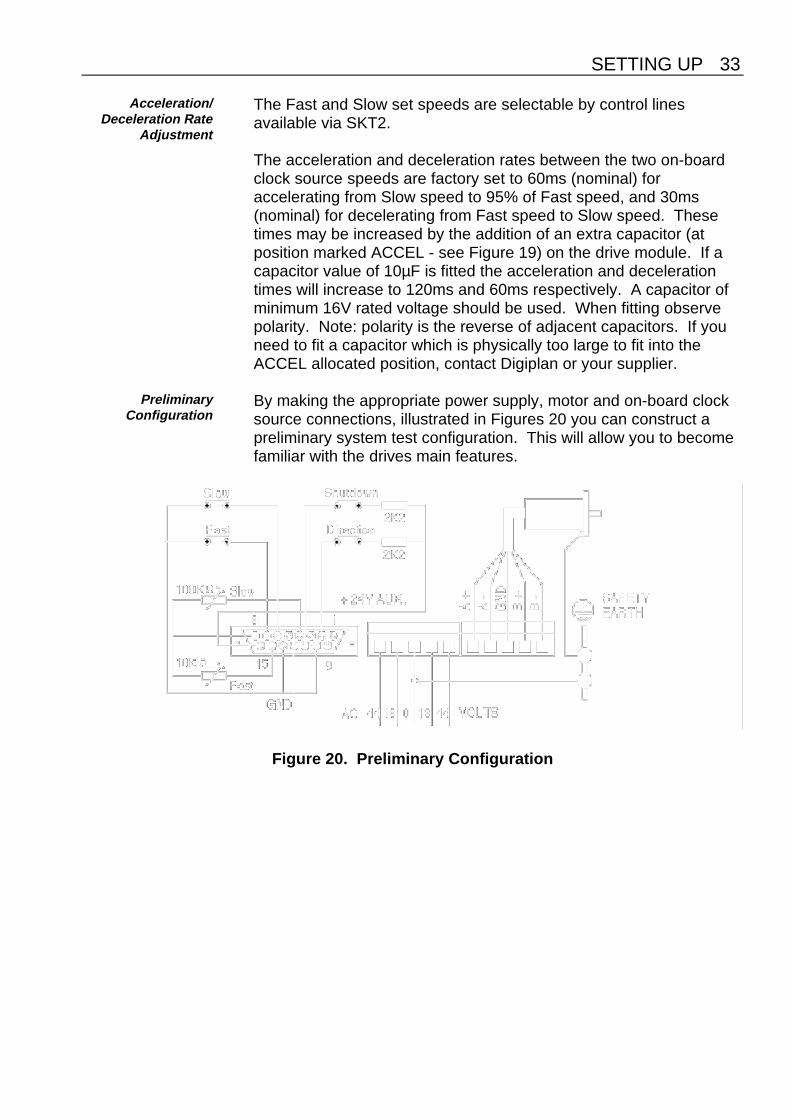
PreliminaryConfiguration
By making the appropriate power supply, motor and on-board clocksource connections, illustrated in Figures 20 you can construct apreliminary system test configuration. This will allow you to becomefamiliar with the drives main features.
Figure 20. Preliminary Configuration

34 OEM 230 SERIES DRIVE USER GUIDE
Before you power-up the drive you must ensure the power supplyand motor cables are correctly connected and the motor securelyheld. Once you are satisfied that all connections are correctly made,apply power to the drive which will power up in its enabled state(evident by holding torque on the motor).
Closing the shutdown switch will de-energise the drive, removingholding torque from the motor.
A latched fault condition may be cleared by cycling the shutdowncommand.
You can check for correct operation of the drive by performing thefollowing test sequence:
1. Close the slow switch and check for rotation.
2. Check speed varies with alteration of the slow speed pot.
3. Close the direction switch and check the motor reverses.
4. Close the fast switch and check for rotation at high speed, varyingwith alteration of the fast pot setting.
5. Open the fast and slow switches and check rotation stops.
This completes the test sequence. Remove power from the drive.

MAINTENANCE & TROUBLESHOOTING 35
MAINTENANCE & TROUBLESHOOTING
Maintenance Take care, unexpected motion may occur at any time whilsttroubleshooting motion control equipment.
Routine maintenance is not necessary, but occasional checking ofthe following points is recommended.
Motor Maintenance You should inspect the motor to ensure that no bolts or couplingshave become loose during operation. This will prevent minor defectsfrom developing into more serious problems.
You should inspect the motor cable or leads periodically for signs ofwear. You should not make very tight bends or apply excessivetensile force to the cable during normal operation. Check all cableconnectors.
Drive Maintenance Check that the drive is free of loose particles and has a free flow ofair over its entire surface. Enclosures must be connected to earthground to provide a low-impedance path for ground-fault or noise-induced currents. Check the security of the ground connections.
Troubleshooting Use the following information to help in identifying the problem. Ifthe problem persists, call one of the numbers at the front of this UserGuide for engineering assistance.
Motor Fails to Move Test the motor to see if it has holding torque. If there is no holdingtorque, here are some probable causes:
• There is no power.
• Current selection links are not set properly.
• There are bad connections or bad cables in the power supplycircuit. Disconnect the power connector, then use a meter tomonitor continuity in the power circuits.
• There are bad connections or bad cables in the motor circuit.Disconnect the power to the drive and remove the motorconnector. Using a meter, check the continuity in the motorcircuit between pins A+ and A- of the motor connector. Repeatfor pins B+ and B-.
• Check the resistance of the motor and cables to make sure thatshorts do not exist between phases or to earth GND. The

36 OEM 230 SERIES DRIVE USER GUIDE
resistance across each motor phase should be consistent andthere should be no connection between motor phases andbetween each phase and earth ground.
• Check the motor cables for signs of damage.
• The shutdown input may be active.
• The drive fuses may be blown. Disconnect power from the drive,remove the drive from the rack, and inspect the line fuses FS1and FS2, on the OEM Drive card. If the logic fuse FS1 isblown, try replacing it. If the motor supply fuse FS2 isblown, return the drive for repair.
If the unit has holding torque and the motor shaft still fails to move,here are some probable causes:
• The load is jammed. You should hear the drive attempting tomove the motor. Remove power from the driver and verify thatyou can move the load manually away from the point of the jam.
• Clock pulses are not reaching the drive, or the signal levels areinadequate. If possible, check the signal levels with anoscilloscope or DMM.
Motor Stalls A motor stall during acceleration may be caused by one or more ofthe following factors:
• The torque requirements may be excessive.• The acceleration ramp may be too steep - lower acceleration may
be required. Check the torque/speed curves in the publisheddata and make sure you are trying to run the motor within thesystem capabilities.
• The load inertia and rotor inertia may be grossly mismatched.• System resonance.
If the motor stalls during the constant velocity portion of a move, theshaft and/or coupler may be damaged or binding due to impropercoupling or excessive motor load.
A stall may occur if the link setting for the motor current selection isincorrect. The motor may not be receiving enough current to drivethe load.
Motor is Jerky orWeak
Check that there are no mechanical problems at the load causingvariable loading condition. Disconnect the motor from the load and

MAINTENANCE & TROUBLESHOOTING 37
run it without a load connected. Check the link settings for propercurrent settings.
Motor Overheats If the motor exceeds its maximum motor case temperature rating,failure will eventually result. Check your link settings to ensure thatthe current setting is correct for the motor you are using.
Motor ShaftDevelops Signs of
Wear
The motor shaft may wear prematurely if there is foreign materialrubbing against the shaft, or if the load is not coupled properly.Check couplings for tightness.
Returning theSystem
Contact the Parker Automation Technology Centre or the machinerymanufacturer who supplied the product. Equipment for repair shouldNOT be returned directly to Digiplan without prior authorisation.Repairs will be carried out by Digiplan but will be processed via yoursupplier.
Digiplan may at their discretion authorise direct shipment to and fromPoole or Rohnert Park, but only by prior arrangement with yoursupplier. Existing UK and USA customers who purchase equipmentdirectly from Digiplan should contact Poole or Rohnert Park forfurther information (contact numbers are at the front of this UserGuide).

38 OEM 230 SERIES DRIVE USER GUIDE
INDEX 39
Index
24V auxiliary output 19
Acceleration capacitor 31Acceleration rate 31
Bipolar rating 12
Clock Monitor 17Clock source control inputs 18Conducted emissions 24Control signal wiring (EMC) 28Control signals. 5Cooling considerations 22
DC Operation 11Direction input 17Direction of rotation 14Drive Links 29Drive Maintenance 33Drive, power-up checks 32Drive, testing configuration 31
EMC Installation 23EMC mains filter installation 25Enclosure Considerations 22Environmental 22
Fast Rate 19Fault LED indicator 18Fault output 18Ferrite absorber handling procedures 28Ferrite absorber specification 28Full step mode 29Fuses 4Fuses blown 34
Grounding 9
Half step mode 29
Input Circuit Links 20Input Circuits 19Installation Considerations 22Insulation rating of motor 14
Keying Pegs 8
Line fuse type 10Line fuse values 10Link Locations 30
Maintenance 33Motor Cable 14Motor Connections 14Motor connections (EMC) 27Motor current selection 29Motor Earth 14Motor Fails to Move 33Motor Insulation 14Motor is Jerky or Weak 34Motor Leads 14Motor Maintenance 33Motor Overheats 34Motor Selection 12Motor Shaft Develops Signs of Wear 35Motor specification 4Motor Stalls 34Mounting Hole Locations 23
OEM 230 Series 1Output Circuits 21Overheating 34
Parallel connections 16Power Connections 7Product Description 1
Rack tie bar 24Radiated emissions 24Rate adjustment 17Returning the System 35
Series connection 15SETTING UP 29Shutdown input 18Signal Connections 17Single Ended Input 20Slow Rate 17

40 OEM 230 SERIES DRIVE USER GUIDE
SPECIFICATION 3Stalling 34Standby link 29Step 29Step input 17
Temperature of motor warning 14Temperature rating of motor cable 14Temperature, operating 22Temperature, storage 22Transformer Connections 9Transformer Wiring 10Troubleshooting 33
Unipolar rating 12
Wiring Guidelines 9