oem - supercontrols s.a · oem carel code +030221791 - rel. 2.0, 20/01/05 8 the appliance can be...
TRANSCRIPT

OEM
User manual


We wish to save you time and money! We can assure you that the thorough reading of this manual will guarantee correct installation and safe use of the product described.


IMPORTANT WARNINGS
BEFORE INSTALLING OR HANDLING THE APPLIANCE, PLEASE CAREFULLY READ AND FOLLOW THE INSTRUCTIONS AND SAFETY REGULATIONS CONTAINED IN THIS MANUAL AND INDICATED ON THE LABELS ATTACHED TO THE UNIT. INSTRUCTION SHEET +050003755 OF THE CP* CONTROL BOARD IS AN INTEGRAL PART OF THIS MANUAL! CAREFULLY KEEP INSTRUCTION SHEET +050003755 TOGETHER WITH THIS MANUAL! This humidifier produces non-pressurised steam by means of electrodes immersed in the water contained in the cylinder-boiler (hereafter referred to as the cylinder). The electrodes pass electric current through water, which, acting as electrical resistance, heats up. The steam produced is used to humidify rooms or industrial processes, by means of special distributors. As the quality of the water in use affects the evaporation process, the appliance may be supplied with untreated water as long as it is drinkable and not demineralised (refer to supply water requirements); the evaporated water is automatically topped up using of a fill valve. This appliance has been designed exclusively to humidify rooms directly or in ducts through a distribution system. Installation, use and maintenance shall be carried out according to the instructions contained in this manual. The environmental conditions and the power supply voltage must comply with the specified values. Any other use and modification to the appliance not expressly authorised by the manufacturer shall be considered as improper. Liability for injuries or damage caused by improper use lies exclusively with the user. Please note that the unit contains live electrical devices and hot surfaces. All service and/or maintenance operations must be carried out by specialist and qualified personnel aware of the necessary precautions and able to operate properly. Disconnect the unit from the mains before accessing any internal parts. The appliance must be installed in compliance with the local regulations in force. The local safety regulations in force must be applied in all cases. Disposal of the parts of the humidifier: the humidifier is made up of metal and plastic components. All these parts must be disposed of in compliance with the local legislation on waste disposal. Materials warranty: 2 years (from the date of production, consumable parts excluded – e.g. the cylinder). Certification: the quality and safety of Carel’s products are guaranteed by the ISO 9001 certified design and production system,
as well as by the mark.


INDEX 1. MODELS AND DESCRIPTION OF THE COMPONENTS....................................................................................................................... 3
1.1 Description of the components ............................................................................................................................................................. 3 2. INSTALLATION: dimensions, weights, hose connections........................................................................................................................... 6
2.1 Positioning............................................................................................................................................................................................ 6 2.2 Connecting the hoses............................................................................................................................................................................ 8 2.3 Drain..................................................................................................................................................................................................... 9 2.4 Supply .................................................................................................................................................................................................. 9 2.5 Checks.................................................................................................................................................................................................. 9 2.6 Installation of the steam hose and condensate return hose ................................................................................................................. 10 2.7 Characteristics of the water ................................................................................................................................................................ 10
2.7.1 Supply water .................................................................................................................................................................................. 10 2.8 Drain water......................................................................................................................................................................................... 11
3. OEM WITH FRAME .................................................................................................................................................................................... 12 3.1 Introduction ........................................................................................................................................................................................ 12 3.2 Frame ................................................................................................................................................................................................. 12 3.3 Control board...................................................................................................................................................................................... 12 3.4 Water fill ............................................................................................................................................................................................ 12 3.5 Drain................................................................................................................................................................................................... 13 3.6 Water circuit....................................................................................................................................................................................... 13 3.7 Structure ............................................................................................................................................................................................. 13 3.8 Switch and manual drain button ......................................................................................................................................................... 13 3.9 External connections .......................................................................................................................................................................... 13 3.10 Power cable ........................................................................................................................................................................................ 13 3.11 Current transformer (TAM)................................................................................................................................................................ 13 3.12 LED panel .......................................................................................................................................................................................... 13 3.13 Technical specifications ..................................................................................................................................................................... 13
4. ELECTRICAL CONNECTIONS (with CAREL controller, model CP)................................................................................................... 14 4.1 Single-phase wiring diagram, EXTERNAL TAM (CP1 *) ................................................................................................................ 14 4.2 Single-phase wiring diagram, INTERNAL TAM (CP2 *) ................................................................................................................. 15 4.3 Single-phase wiring diagram, INTERNAL TAM with contactor (CP4 *) ......................................................................................... 16 4.4 Single-phase wiring diagram, EXTERNAL TAM with contactor (CP3 *) ........................................................................................ 17 4.5 Three-phase wiring diagram, EXTERNAL TAM with contactor (CP3 *) ......................................................................................... 18 4.6 Three-phase wiring diagram, INTERNAL TAM with contactor (CP4 *) .......................................................................................... 19 4.7 Three-phase wiring diagram, KUE with frame, INTERNAL TAM with contactor (CP4 *) .............................................................. 20 4.8 Single-phase wiring diagram, KUE with frame, INTERNAL TAM with contactor (CP4 *) ............................................................. 21 4.9 Three-phase wiring diagram, EXTERNAL TAM with contactor (CP3 *) ......................................................................................... 22
5. STARTING, CONTROL AND SHUTDOWN............................................................................................................................................. 23 5.1 Preliminary checks ............................................................................................................................................................................. 23 5.2 Starting ............................................................................................................................................................................................... 23
5.2.1 Starting with an empty cylinder ..................................................................................................................................................... 23 6. MAINTENANCE AND SPARE PARTS ..................................................................................................................................................... 24
6.1 Replacing the cylinder........................................................................................................................................................................ 24 6.2 Maintenance of the other components in the water circuit ................................................................................................................. 25 6.3 Component replacement..................................................................................................................................................................... 26
6.3.1 Fuses in the auxiliary circuits......................................................................................................................................................... 26 6.4 Spare parts.......................................................................................................................................................................................... 27
6.4.1 SINGLE-PHASE humidifiers: ....................................................................................................................................................... 27 6.4.2 Spare parts for special applications ................................................................................................................................................ 27 6.4.3 THREE-PHASE humidifiers: ........................................................................................................................................................ 27 6.4.4 Spare parts for special applications ................................................................................................................................................ 28
6.5 Troubleshooting ................................................................................................................................................................................. 29 6.6 Alarms................................................................................................................................................................................................ 29
7. OPERATING PRINCIPLE, CONTROL AND OTHER FUNCTIONS.................................................................................................... 30 7.1 Operating principle............................................................................................................................................................................. 30 7.2 Control principles ............................................................................................................................................................................... 30
7.2.1 ON/OFF control - CP controllers ................................................................................................................................................... 30 7.2.2 Proportional control - CP controllers ............................................................................................................................................. 30
8. TECHNICAL SPECIFICATIONS............................................................................................................................................................... 31

OEM
CAREL code +030221791 - rel. 2.0, 20/01/05 3
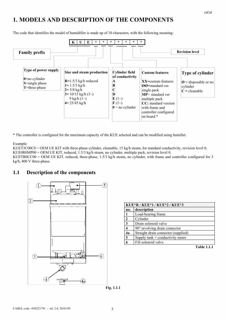
1. MODELS AND DESCRIPTION OF THE COMPONENTS The code that identifies the model of humidifier is made up of 10 characters, with the following meaning:
K U E * * * * * * * * The controller is configured for the maximum capacity of the KUE selected and can be modified using humiSet. Example: KUET3C00C0 = OEM UE KIT with three-phase cylinder, cleanable, 15 kg/h steam, for standard conductivity, revision level 0; KUE0R0MP00 = OEM UE KIT, reduced, 1.5/3 kg/h steam, no cylinder, multiple pack, revision level 0. KUETR0CC00 = OEM UE KIT, reduced, three-phase, 1.5/3 kg/h steam, no cylinder, with frame and controller configured for 3 kg/h, 400 V three-phase.
1.1 Description of the components
Fig. 1.1.1
KUE*R / KUE*1 / KUE*2 / KUE*3 no. description 1 Load-bearing frame 2 Cylinder 3 Drain solenoid valve 4 90° revolving drain connector 4a Straight drain connector (supplied) 5 Supply tank + conductivity meter 6 Fill solenoid valve Table 1.1.1
Cylinder field of conductivity A B C D E (1~) F (1~) 0 = no cylinder
Size and steam production
R=1.5/3 kg/h reduced 1= 1.5/3 kg/h 2= 5/8 kg/h 3= 10/15 kg/h (3~) 9 kg/h (1~) 4= 25/45 kg/h
Family prefix
Type of power supply 0=no cylinder S=single phase T=three-phase
Revision level
Type of cylinder Ø = disposable or no cylinder C = cleanable
Custom features XX=custom features ØØ=standard ver. single pack MP= standard ver multiple pack CC: standard version with frame and controller configured on board *

OEM
CAREL code +030221791 - rel. 2.0, 20/01/05 4
Fig. 1.1.1 A
1
5
2
6
43 Fig. 1.1.1 B
KUE***CC** no. description * For the details of the components see Chap.3 Table 1.1.1
KUE*4 no. description 1 Load-bearing frame 2 Cylinder 3 Drain pump 4 Supply/drain manifold 5 Supply tank + conductivity meter 6 Fill solenoid valve Table 1.1.1

OEM
CAREL code +030221791 - rel. 2.0, 20/01/05 5
CP1* CP2* CP3* CP4*
CP* control boards (also see instruction sheet +050003755 for the boards)
Fig. 1.1.1a. External TAM (current transformer) (required only for boards CP1* and CP3*)
Fig. 1.2.2 refers to the following table for the description.
* Device used to prevent the water in the supply tank from exceeding the safety level (for example due to a malfunction of the controller or leaks from the fill solenoid valve, or back pressure). The supply tank is fitted with an overflow diaphragm that releases the excess water introduced, draining it through a special pipe. The overflow diaphragm is below the fill to prevent backflow into the supply hose.
no. description 1 fill solenoid valve 2 flow limiter 3 supply hose 4 fill hose 5 overflow pipe 6 electrodes for measuring the
conductivity 7 supply tank - overflow * 8 high level electrodes 9 steam outlet 10 electrodes (2/6 in the single-
phase model, 3/6 in the three-phase model)
11 cylinder casing 12 bottom filters 13 drain solenoid valve 14 corrugated drain pipe 15 drain column 16 drain pump Table 1.2.1
Fig. 1.2.2

OEM
CAREL code +030221791 - rel. 2.0, 20/01/05 6
2. INSTALLATION: dimensions, weights, hose connections 2.1 Positioning
• To favour steam distribution, position the appliance so as to minimise the length of the steam outlet pipe (max 4 m). The unit has been designed for wall mounting; the wall must be able to support the weight of the unit during operation.
• The cylinder of the humidifier may reach temperatures above 60°C. • Make sure that the humidifier is level.
KUE*R / KUE*1 / KUE*2 / KUE*3
Italian English Raccordo di alimentazione 3/4 “ Gas maschio Supply connection 3/4“ Gas male Raccordo di drenaggio diam. 32 mm Drain connector dia. 32mm N. 4 fori di fissaggio 6x10 4 fastening holes 6x10

OEM
CAREL code +030221791 - rel. 2.0, 20/01/05 7
KUE*4 L
H
A1
A2S2
S1
V3
V1
P
S
V
X X1
Y
Y1
KUE***CC**

OEM
CAREL code +030221791 - rel. 2.0, 20/01/05 8
The appliance can be either wall-mounted by using the appropriate fastening holes or installed on bracket so that the water connections can be completed.
2.2 Connecting the hoses The installation of the humidifier requires the connection to the water supply and drain hoses.
models KUE*R* KUE*1* KUE*2* KUE*3* KUE*4*
Weights ( kg ) Empty 1.2 1.6 2.9 3.5 7.2 Packaged 2.0 2.4 3.7 4.3 8.9 Installed 3.7 5.5 8.9 13.8 39 Installed + frame 7.7 10 14.3 21
H 300 391 412 512 630 L 160 160 185 225 390 P 170 170 220 230 350 dia. V 22/30 22/30 30 30 40 dia. S 32 32 32 32 40 V1 75 75 93 112.5 220 V2 95 95 92 112.5 V3 95 95 124 135 181 V4 54 54 20 26 V5 16/17 16/17 37 37 S1 46 46 54 77 28 S2 114 114 131 148 70 S3 98 98 118 118 S4 40-50 40-50 40-50 40-50
Dimensions (mm)
S5 13/15/30 13/15/30 13/15/30 13/15/30 A1 19.5 19.5 19.5 19.5 55 Hose connection A2 53 53 53 53 120 X 36 36 47 68 90 X1 90 90 90 90 210 Y 146 146 213 288 494
Mounting distances
Y1 68 68 68 69 106 HC 380 470 502 590 LC 277 277 302 354 LC1 196 196 221 273 LC2 21 21 21 21 LC3 56.5 115 115 115 LC4 80 80 80 80 PC 198 198 248 260
Dimensions of the frame (mm)
INT 142.3 142.3 192.3 204.3 Table 2.1.1
supply
drain
drain trap
filter
tap
Drain for KUE≈4*

OEM
CAREL code +030221791 - rel. 2.0, 20/01/05 9
2.3 Drain
2.4 Supply
To simplify installation, it is recommended to use the CAREL hose with an inside diameter of 6 mm and an outside diameter of 8 mm (code 1312350APN) and the revolving ¾G connection, either straight (code 9995727ACA) or 90° (code 9995728ACA), available upon request. A shut-off tap and a mechanical filter should be installed to trap any solid impurities. The drain water is connected using a section of rubber or plastic hose resistant to 100°C, with a recommended inside diameter of 32 mm or 40 mm for the 25 to 45kg/h models (compliant with DIN 19535, UNI 8451/8452). The drain connector is suitable for heat sealing with polypropylene drain pipes. IMPORTANT WARNING: the drain hose must be free, without backpressure and with a drain trap immediately downstream of the connection to the humidifier.
2.5 Checks The following conditions represent correct water connection:
• installation of a shut-off tap in the supply water line; • presence of a mechanical filter in the supply water line; • water temperature and pressure within the allowed values; • drain hose resistant to temperatures of 100°C; • minimum inside diameter of the drain hose of 25 mm or 36 mm for the 25 to 45kg/h models; • minimum slope of the drain hose greater than or equal to 5°; • electrically non-conductive sleeve. • presence of a drain trap in the drain hose
IMPORTANT WARNING: when installation is completed, flush the supply hose for around 30 minutes by piping the water directly into the drain without sending it into the humidifier. This will eliminate any scale or processing residues that may block the fill valve or cause foam when boiling.
models
KUE*R* KUE*1* KUE*2* KUE*3* KUE*4* Max. instant drain flow l/min ~ 4 ~ 4 ~ 4 ~ 4 ~ 22.5 Darin water attachment (mm) 32 32 32 32 40
Min. ID of the drain hose 25 25 25 25 36
models KUE*R* KUE*1* KUE*2* KUE*3* KUE*4*
Max. instant supply flow l/min 0.6 0.6 0.6 1.2 4
Supply water attachment ¾ ”G Male
¾ ”G Male
¾ ”G Male ¾ ”G Male ¾ ”G Male
Min. ID of the sill pipe or hose 6 6 6 6 6
Table 2.4.1

OEM
CAREL code +030221791 - rel. 2.0, 20/01/05 10
2.6 Installation of the steam hose and condensate return hose The connection between humidifier and distributor must be made using a pipe
suitable for this purpose, such as the CAREL hose. Avoid the formation of pockets or traps where the condensate may
accumulate. Make sure that the hose is not choked due to tight curves or twisting. Fasten the ends of the hose with screw clamps.
The pipe may run according to either of the two following solutions:
IMPORTANT WARNING: the length of the steam pipe should not exceed 4 m. To allow the drain trap in the steam condensate hose to operate properly, it must be filled with water before starting the humidifier.
2.7 Characteristics of the water 2.7.1 Supply water The humidifier must be supplied with mains water, wit the following characteristics: pressure between 0.1 and 0.8 MPa (1 to 8 bar, 14.5 to 116 psi); temperature between 1 and 40 °C; instant flow rate not lower than the rated fill solenoid valve flow rate (refer to table 2.4.1); connection type ¾”G male.
Steam hose
Condensate hose

OEM
CAREL code +030221791 - rel. 2.0, 20/01/05 11
LIMITS LIMIT VALUES FOR THE SUPPLY WATER WITH MEDIUM-HIGH CONDUCTIVITY IN
AN IMMERSED ELECTRODE HUMIDIFIER Min Max Hydrogen ions pH - 7 8.5 Specific conductivity at 20°C σR, 20°C - µS/cm 300 1250Total dissolved solids TDS - mg/l (1) (1) Dry residue at 180°C R180 - mg/l (1) (1) Total hardness TH - mg/l CaCO3 100(2) 400 Temporary hardness - mg/l CaCO3 60(3) 300 Iron + Manganese - mg/l Fe + Mn 0 0.2 Chlorides - ppm Cl 0 30 Silica - mg/l SiO2 0 20 Residual chlorine - mg/l Cl- 0 0.2 Calcium sulphate - mg/l CaSO4 0 100 Metallic impurities - mg/l 0 0 Solvents, diluents, soaps, lubricants - mg/l 0 0
(1) Values depending on specific conductivity; in general: TDS ≅ 0.93 * σ20; R180 ≅ 0.65 * σ20 (2) not lower than 200% of the chloride content in mg/l of Cl-
(3) not lower than 300% of the chloride content in mg/l of Cl-
Table 2.7.1.1
LIMITS LIMIT VALUES FOR THE SUPPLY WATER WITH MEDIUM-LOW CONDUCTIVITY IN AN IMMERSED ELECTRODE HUMIDIFIER Min Max Hydrogen ions pH - 7 8.5 Specific conductivity at 20°C σR, 20°C - µS/cm 125 500 Total dissolved solids TDS - mg/l (1) (1) Dry residue at 180°C R180 - mg/l (1) (1) Total hardness TH - mg/l CaCO3 50(2) 250 Temporary hardness - mg/l CaCO3 30(3) 150 Iron + Manganese - mg/l Fe + Mn 0 0.2 Chlorides - ppm Cl 0 20 Silica - mg/l SiO2 0 20 Residual chlorine - mg/l Cl- 0 0.2 Calcium sulphate - mg/l CaSO4 0 60 Metallic impurities - mg/l 0 0 Solvents, diluents, soaps, lubricants - mg/l 0 0
(1) Values depending on specific conductivity; in general: TDS ≅ 0.93 * σ20; R180 ≅ 0.65 * σ20 (2) not lower than 200% of the chloride content in mg/l of Cl-
(3) not lower than 300% of the chloride content in mg/l of Cl-
Table 2.7.1.2
Warning: no relation can be demonstrated between water hardness and conductivity. IMPORTANT WARNING: do not treat water with softeners! This could cause corrosion of the electrodes or the formation of foam, leading to potential operating problems or failures. Avoid: 1. using well water, industrial water or water drawn from cooling circuits; in general, avoid using potentially contaminated water,
either from a chemical or bacteriological point of view; 2. adding disinfectants or corrosion inhibiters to water, as these substances are potentially irritant.
2.8 Drain water Inside the humidifier the water boils and is transformed into steam, without the addition of any substances. The drain water, as a result, contains the same substances that are dissolved in the supply water, yet in greater quantities, depending on the concentration in the supply water and the set draining cycles, and may reach temperatures of 100°C. Not being toxic, it may be drained into the sewage system. The drain connector has an external diameter of 32 mm.

OEM
CAREL code +030221791 - rel. 2.0, 20/01/05 12
3. OEM WITH FRAME 3.1 Introduction This is a special OEM version fitted on a frame, with a pre-wired control board, switch and drain button.
Fig. 3.1.1
Italian English Cilindro Cylinder Struttura idraulica Water circuit support structure Conn. elett. carico Fill elect. conn. Scheda Board Carpenteria Frame
3.2 Frame The humidifiers are supplied with a compact, openable, hot galvanised metal frame, complete with handle and screw closing. The frame includes a case for housing the control board
3.3 Control board The controller used for these OEM units is the CP4 with microprocessor, complete with software for immersed electrode humidifiers. Type of configuration, ON/OFF or 0 to 10 V proportional. Built-in current sensor 24 Vac power supply AFS antifoam algorithm Possibility of remote ON/OFF (AB-AB) Outputs: 1 x 250 Vac relay, 5 Amp (2 Amp) for electrode power supply 1 x 250 Vac relay, 5 Amp (2 Amp) for alarm output Possibility of RS485 serial connection (optional TACP485000) Can be configured using the HUMISET000 programming kit
3.4 Water fill The fill solenoid valve with ¾”G male connector is located on the right side of the frame, with the measurements shown in table 2.1.1 (LC3, LC4), so as to make this accessible for cleaning the filter on the solenoid valve when the unit is installed.

OEM
CAREL code +030221791 - rel. 2.0, 20/01/05 13
3.5 Drain Drain assembly made up of a manifold and drain solenoid valve with 90° connector and 32 mm diameter fitting, with the possibility to replace the drain with a straight pipe, supplied.
3.6 Water circuit Water circuit with supply tank plus conductivity meter and cylinder fill, drain and overflow hoses.
3.7 Structure Back made from polypropylene reinforced with fibreglass, cylinder secured by convenient strap closing system.
3.8 Switch and manual drain button The humidifier is fitted with a switch from turning the unit on/off and a button for the manual drain function.
3.9 External connections The unit can be managed externally via 2 connectors: • a four pin connector used to control a phase of the power supply to the external power contactor coil (terminals 1,2) and for the
24 Vac power supply to the auxiliary circuits (terminals 3, 4); • the second 3 pin connector is used for the connection to the probe (see diagram 4.7).
3.10 Power cable The power cable is 3 metres long, is flame retardant and is supplied with a rubber cable gland. One end has special cable terminals for connection to the cylinder, and the other end is free.
3.11 Current transformer (TAM) This is fitted on the control board, and monitors one of the phases of the power supply to measure the current.
3.12 LED panel The operation the humidifier is displayed using a panel fitted with coloured LEDs, with the following meanings green: power present yellow: steam production in progress red: alarm signal These events are indicated by sequences of flashes; for the meanings see the instruction sheet +050003755
3.13 Technical specifications Steam production, weights and dimensions see Chap. 2, page 7 The index of protection is IP20.
OEM
CAREL code +030221791 - rel. 2.0, 20/01/05 14
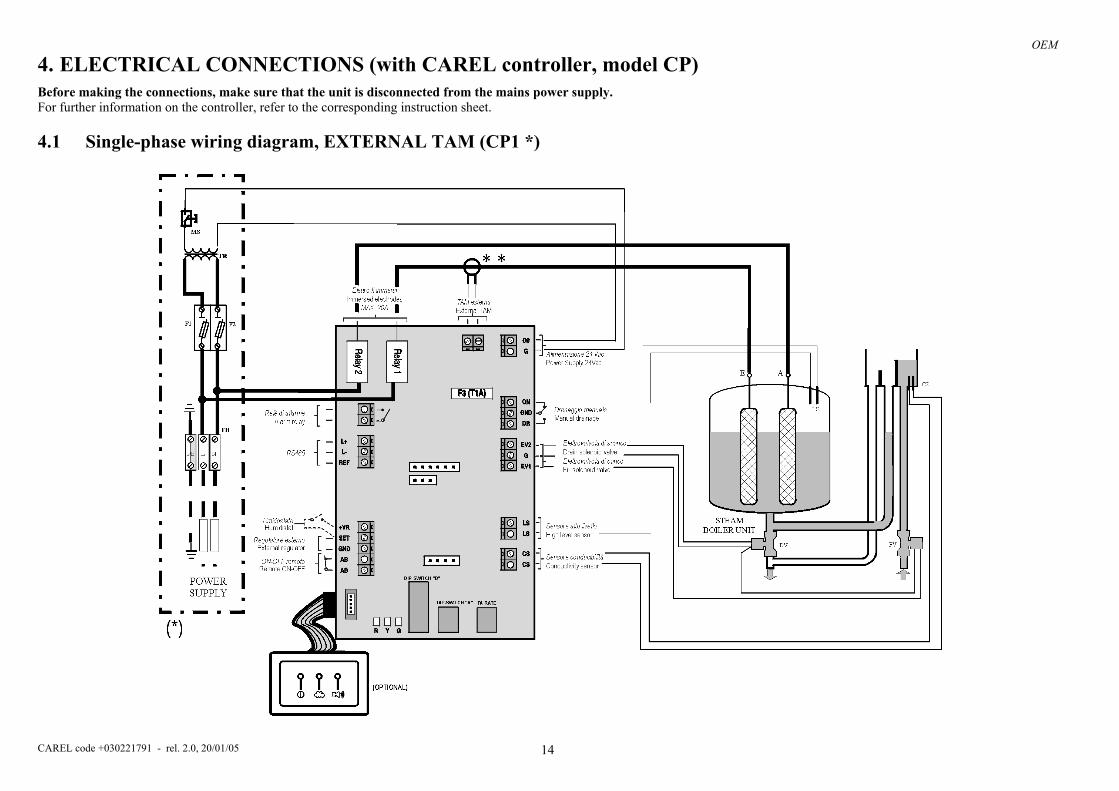
4. ELECTRICAL CONNECTIONS (with CAREL controller, model CP) Before making the connections, make sure that the unit is disconnected from the mains power supply. For further information on the controller, refer to the corresponding instruction sheet.
4.1 Single-phase wiring diagram, EXTERNAL TAM (CP1 *)
OEM
CAREL code +030221791 - rel. 2.0, 20/01/05 15
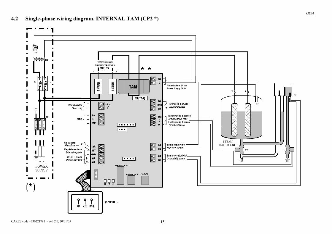
4.2 Single-phase wiring diagram, INTERNAL TAM (CP2 *)

OEM
CAREL code +030221791 - rel. 2.0, 20/01/05 16
4.3 Single-phase wiring diagram, INTERNAL TAM with contactor (CP4 *)

OEM
CAREL code +030221791 - rel. 2.0, 20/01/05 17
4.4 Single-phase wiring diagram, EXTERNAL TAM with contactor (CP3 *)

OEM
CAREL code +030221791 - rel. 2.0, 20/01/05 18
4.5 Three-phase wiring diagram, EXTERNAL TAM with contactor (CP3 *)

OEM
CAREL code +030221791 - rel. 2.0, 20/01/05 19
4.6 Three-phase wiring diagram, INTERNAL TAM with contactor (CP4 *)

OEM
CAREL code +030221791 - rel. 2.0, 20/01/05 20
4.7 Three-phase wiring diagram, KUE with frame, INTERNAL TAM with contactor (CP4 *)

OEM
CAREL code +030221791 - rel. 2.0, 20/01/05 21
4.8 Single-phase wiring diagram, KUE with frame, INTERNAL TAM with contactor (CP4 *)

OEM
CAREL code +030221791 - rel. 2.0, 20/01/05 22
4.9 Three-phase wiring diagram, EXTERNAL TAM with contactor (CP3 *)
L1 L2 L3 PE
TB
POWERSUPPLY
Alimentazione 24 Vac Power Supply 24Vac
Drenaggio manuale Manual drainage
Elettrovalvola di scarico Drain solenoid valveElettrovalvola di carico Fill solenoid valve
TAM esterna External TAM
Sensore alto livello High level sensor
Sensore conducibilitàConductivity sensorON-OFF remoto
Remote ON-OFF
Relè di allarme Alarm relay
Regolatore esterno External regulator
RS485
Elettrodi immersi Immersed electrodes
MAX. 5A
(OPTIONAL)
Umidostato Humidistat
DIP-SWITCH "B"
DIP-SWITCH "A" TA RATE
* *
(* )RD
F1
F2
F3
MS
RD
F4
DP
TR
K
(*) material not supplied by CAREL

OEM
CAREL code +030221791 - rel. 2.0, 20/01/05 23
5. STARTING, CONTROL AND SHUTDOWN IMPORTANT WARNINGS:
1. Before starting the unit, check that the humidifier is in good condition, that there are no water leaks and that the electrical parts are dry.
2. Do not power the appliance if it is damaged or even partially wet! When installation is completed, flush the supply hose for around 30 minutes by piping the water directly into the drain without sending it into the humidifier. This will eliminate any scale or processing residues that may block the fill valve or cause foam when boiling.
5.1 Preliminary checks Before starting the humidifier, check that: • the water and electrical connections and the steam distribution system have been completed according to the instructions contained
in this manual; • the water shut-off tap to the humidifier is open; • the line fuses are installed and intact; • terminals AB on the CP control board are jumpered or connected to the remote ON/OFF contact; also check that the ON/OFF
contact is closed; • the steam outlet pipe is not choked.
5.2 Starting 5.2.1 Starting with an empty cylinder This phase will be performed automatically when the unit is started: the rated production will be reached after a certain time (this times depends considerably on the conductivity of the supply water and may last a number of some hours).

OEM
CAREL code +030221791 - rel. 2.0, 20/01/05 24
6. MAINTENANCE AND SPARE PARTS
6.1 Replacing the cylinder IMPORTANT WARNING: the cylinder may be hot. Allow it to cool before touching it or use protective gloves. To access the cylinder: • completely drain the water contained in the cylinder; • turn the appliance off and open the mains power disconnecting switch (safety procedure); • open and remove the cover; • remove the steam hose from the cylinder; • disconnect the electrical connections from the top of the cylinder; • release the cylinder from the fastening device and lift it up to remove it; • fit the new cylinder in the humidifier by performing the previous operations in reverse. Cylinder maintenance (refer to cylinders instruction sheet) The life of the cylinder depends on a number of factors, including: the complete filling with lime scale and/or the partial or complete corrosion of the electrodes, the correct use and sizing of the humidifier, the output, and the quality of the water, as well as careful and regular maintenance. Due to the aging of the plastic and the consumption of the electrodes, even an openable steam cylinder has a limited life, and it is therefore recommended to replace it after 5 years or 10,000 operating hours. Important warnings The humidifier and its cylinder contain live electrical components and hot surfaces, and therefore all service and/or maintenance operations must be performed by expert and qualified personnel, who are aware of the necessary precautions. Before performing any operations on the cylinder, check that the humidifier is disconnected from the power supply; carefully read and follow the instructions contained in the humidifier manual. Remove the cylinder from the humidifier only after having drained it completely using the corresponding button. Check that the model and the power supply voltage of the new cylinder correspond to the data on the rating plate. Periodical checks • After one hour of operation For both disposable and openable cylinders, check that there are no significant water leaks • Every fifteen days or no more than 300 operating hours For both disposable and openable cylinders check operation, that there are no significant water leaks and the general condition of the container. Check that during operation there are no arcs or sparks between the electrodes. • Every three months or no more than 1000 operating hours For disposable cylinders, check operation, that there are no significant water leaks and, if necessary, replace the cylinder; for openable cylinders, check that there are no markedly blackened parts of the container: if this is the case, check the condition of the electrodes, and if necessary replace them together with the O-rings and the cover gasket. • Annually or no more than 2500 operating hours For disposable cylinders, replace the cylinder; for openable cylinders check operation, that there are no significant water leaks, the general conditions of the container, check that there are no markedly blackened parts of the container: if this is the case, check the condition of the electrodes, and if necessary replace them together with the O-rings and the cover gasket. • After five years or no more than 10,000 operating hours For both disposable and openable cylinders, replace the cylinder. After extended use or alternatively when using water with a high salt content, the solid deposits that naturally form on the electrodes may reach the stage where they also stick to the inside wall of the cylinder; in the event of especially conductive deposits, the consequent heat produced may overheat the plastic and melt it, and, in more severe cases, puncture the cylinder, allowing water to leak back into the tank. As a precaution, check, at the frequency recommended further on, the deposits and the blackening of the wall of the cylinder, and replace the cylinder if necessary. CAUTION: always disconnect the appliance before touching the cylinder in the event of leaks, as current may be passing through the water.

OEM
CAREL code +030221791 - rel. 2.0, 20/01/05 25
6.2 Maintenance of the other components in the water circuit IMPORTANT WARNINGS: • when cleaning the plastic components do not use detergents or solvents; • scale can removed using a solution of 20% acetic acid and then rinsing with water. The steam humidifier has just one part that requires periodical replacement: the steam production cylinder. This operation is necessary when the lime scale deposits that form inside the cylinder prevent the sufficient passage of current. This situation is displayed on the controller by an alarm signal. The frequency of this operation depends on the supply water: the higher the content of salts or impurities, the more frequently the cylinder will need replacing.
no description Order code 1 Load-bearing frame
2 Cylinder locking strap 18C499A006
3 Supply tank + conductivity meter 13C119A003
4 Overflow pipe
5 Cylinder fill hose
6 Tank fill hose
UEKT00000*
7 Fill solenoid valve KITVC000**
8 Supply/drain assembly 13C499A030
9 Gasket
10 90° drain connector
11 Straight drain connector (supplied)
KITRACC000
12 Drain solenoid valve 13C499A030
Table 5.2.1* for the complete codes see Table 5.4.1.1 and 5.4.3.1 “ SPARE PARTS” • Fill solenoid valve (Fig. 5.2.1 , part no. 7, 5) After having disconnected the cables and the pipe, remove the solenoid valve and check the condition of the inlet filter; clean if necessary using water and a soft brush. • Supply and drain manifold (Fig. 5.2.1, part no. 8, 2) Check that there are no solid residues in the cylinder attachment, remove any impurities. Check that the seal (O-ring) not is damaged or cracked; if necessary, replace it. • Drain solenoid valve / drain pump (Fig. 5.2.1 , part no. 12, 4) Disconnect the power supply, remove the coil, unscrew the fastening screws and remove the valve body; remove any impurities and rinse. • Supply tank + conductivity meter (Fig. 5.2.1, part no. 3, 6) Check that there are no obstructions or solid particles and that the electrodes for measuring the conductivity are clean, remove any impurities and rinse. • Supply, fill, overflow pipes (Fig. 5.2.1, part no. 4, 5, 6 – 8, 9, 10, 11) Check that these are free and do not contain impurities; remove any impurities and rinse.
Fig. 5.2.1

OEM
CAREL code +030221791 - rel. 2.0, 20/01/05 26
IMPORTANT WARNING: after having replaced or checked the parts in the water circuit, check that the connections have been carried out correctly and the corresponding seals have been used. Re-start the unit and perform a number of fill and drain cycles (from 2 to 4), then, applying the safety procedure, check for any water leaks.
6.3 Component replacement 6.3.1 Fuses in the auxiliary circuits Use fuses with the ratings indicated in Table 5.3.1.
models KUES* KUETR* KUET1* KUET2* KUET3* KUET4* fuses F1-F 2 1 A, GL, 10.3 x 38 in fuse carrier on DIN rail (0605319AXX)
fuse F3 (pump) 1 A, fast-blow 10.3 x 38
in fuse carrier on DIN rail (0605319AXX)
fuse 3 *** 2 A, T, 5x20 Table 5.3.1
***: only on the CP control board.
no description Order code 1 Load-bearing frame
2 Supply/drain manifold 18C499A001
3 Drain circuit 13C499A034
4 Drain pump KITPS00000
5 Fill solenoid valve KITVC00040
6 Supply tank
7 Supply tank cover UEKVASC000
8 Tank fill hose
9 Cylinder fill hose
10 Overflow pipe UEKT0000XL
11 Corrugated drain pipe 13C479A001
Table 5.2.1

OEM
CAREL code +030221791 - rel. 2.0, 20/01/05 27
6.4 Spare parts 6.4.1 SINGLE-PHASE humidifiers: Standard spare parts
model KUESR* KUES1* KUES2* KUES3* Water circuit cylinder locking strap 18C499A006 18C499A006 18C499A006 18C499A006 supply tank + conductivity meter 13C119A003 13C119A003 13C119A003 13C119A003 fill solenoid valve kit KITVC00006 KITVC00006 KITVC00006 KITVC00012 drain solenoid valve kit 13C499A030 13C499A030 13C499A030 13C499A030 drain fittings kit KITRACC000 KITRACC000 KITRACC000 KITRACC000 internal hose kit * UEKT00000S UEKT00000S UEKT00000S UEKT00000S Sealed cylinders 200 to 230 VAC 1~, conductivity 350 to 1250 µS/cm BL0SRF00H1 BL0S1F00H1 BL0S2F00H0 BL0S3F00H0 Electronics control board ver. CP ** CP**
Table 5.4.1.1**: specify kg/h, power supply, options *: hoses must be cut to the required size before installation
6.4.2 Spare parts for special applications The following spare parts are supplied separately from the standard humidifier, therefore they must be ordered separately.
model KUESR* KUES1* KUES2* KUES3* Sealed cylinders 200 to 230 VAC 1~, conductivity 125 to 350 µS/cm
BL0SRE00H1 BL0S1E00H1 BL0S2E00H0 BL0S3E00H0
Table 5.4.2.1
6.4.3 THREE-PHASE humidifiers: Standard spare parts
MODEL KUETR* KUET1* KUET2* KUET3* KUET4* 25kg/h
KUET4* 35kg/h
KUET4* 45kg/h≥400V
Water circuit cylinder locking strap 18C499A006 18C499A006 18C499A006 18C499A006 -- -- -- supply tank + conductivity meter 13C119A003 13C119A003 13C119A003 13C119A003 18C453A008 18C453A008 18C453A008 fill solenoid valve kit KITVC00006 KITVC00006 KITVC00006 KITVC00012 KITVC00040 KITVC00040 KITVC00040 drain solenoid valve kit 13C499A030 13C499A030 13C499A030 13C499A030 KITPS00000 KITPS00000 KITPS00000 drain fittings kit KITRACC000 KITRACC000 KITRACC000 KITRACC000 -- -- -- internal hose kit * UEKT00000S UEKT00000S UEKT00000M UEKT00000M UEKT0000XL UEKT0000XL UEKT0000XL
Sealed cylinders 200 to 230 VAC 3~,conductivity 350 to 1250µS/cm
BL0TRB00H1 BL0T1B00H1 BL0T2B00H0 BL0T3B00H0 BL0T4C00H0 BL0T4B00H0 --
≥400 VAC 3~, conductivity 350 to 750 µS/cm -- BL0T1C00H0 BL0T2C00H0 BL0T3C00H0 ≥400 VAC 3~, conductivity 350 to 1250 µS/cm BL0TRD00H0 BL0T4D00H0 BL0T4D00H0 BL0T4C00H0
Electronics control board ver. CP ** CP** Table 5.4.3.1**: specify kg/h, power supply, options *: hoses must be cut to the required size before installation

OEM
CAREL code +030221791 - rel. 2.0, 20/01/05 28
6.4.4 Spare parts for special applications The following spare parts are supplied separately from the standard humidifier, therefore they must be ordered separately.
MODEL KUETR* KUET1* KUET2* KUET3* KUET4* (25kg/h)
KUET4* (35kg/h)
KUET4* (45kg/h≥400V)
Sealed cylinders 200 to 230 VAC 3~, conductivity 125 to 350 µS/cm BL0TRA00H1 BL0T1A00H1 BL0T2A00H0 BL0T3A00H0 BL0T4B00H0 BL0T4B00H0
400 VAC 3~, conductivity 125 to 350 µS/cm BL0TRC00H1 BL0T1A00H1 BL0T2B00H0 BL0T3B00H0 BL0T4C00H0 BL0T4C00H0 BL0T4B00H0
400 VAC 3~, conductivity 750 to 1250 µS/cm BL0T1D00H1 BL0T2D00H0 BL0T3D00H0
400 VAC 3~, conductivity 125 to 350 µS/cm BL0TRC00H1 BL0T1A00H1 BL0T2B00H0 BL0T3B00H0 BL0T4C00H0 BL0T4C00H0 BL0T4B00H0
400 VAC 3~, conductivity 350 to 1250 µS/cm BL0TRD00H1 BL0T1D00H1 BL0T2D00H0 BL0T3D00H0 BL0T4D00H0 BL0T4D00H0 BL0T4C00H0
460 VAC 3~, conductivity 125 to 350 µS/cm BL0TRC00H1 BL0T1B00H1 BL0T2C00H0 BL0T3C00H0 BL0T4D00H0 BL0T4C00H0 BL0T4C00H0
575 VAC 3~, conductivity 125 to 350 µS/cm BL0T2C00H0 BL0T3C00H0 BL0T4D00H0 BL0T4D00H0 BL0T4D00H0
Openable cylinders 200 to 230 VAC 3~, conductivity 125 to 350 µS/cm BLCTRA00W1 BLCT1A00W1 BLCT2A00W0 BLCT3A00W0 BLCT4B00W0 BLCT4B00W0
200 to 230 VAC 3~, conductivity 350 to 1250 µS/cm BLCTRC00W1 BLCT1B00W1 BLCT2B00W0 BLCT3B00W0 BLCT4B00W0 BLCT4B00W0
400 VAC 3~, conductivity 125 to 350 µS/cm BLCTRC00W1 BLCT1A00W1 BLCT2B00W0 BLCT3B00W0 BLCT4C00W0 BLCT4C00W0 BLCT4B00W0
400 VAC 3~, conductivity 350 to 750 µS/cm BL0TRD00H1 BLCT1C00W1 BLCT2C00W0 BLCT3C00W0
400 VAC 3~, conductivity 350 to 1250 µS/cm BL0TRD00W1 BLCT4D00W0 BLCT4D00W0 BLCT4C00W0
400 VAC 3~, conductivity 750 to 1250 µS/cm BLCT1D00W1 BLCT2D00W0 BLCT3D00W0
460/575 VAC 3~, conductivity 125 to 350 µS/cm BLCT2C00W0 BLCT3C00W0 BLCT4D00W0
460/575 VAC 3~, conductivity 350 to 1250 µS/cm BLCT2D00W0 BLCT3D00W0 BLCT4D00W0
460 VAC 3~, conductivity 125 to 350 µS/cm BLCTRC00W1 BLCT1B00W1 BLCT4C00W0 BLCT4C00W0
460 VAC 3~, conductivity 350 to 1250 µS/cm BLCTRD00W1 BLCT1D00W1 BLCT4D00W0 BLCT4D00W0
575 VAC 3~, conductivity 125 to 350 µS/cm BLCT4D00W0 BLCT4D00W0
575 VAC 3~, conductivity 350 to 1250 µS/cm BLCT4D00W0 BLCT4D00W0
electrode kit (200 to 230 VAC 3~, 125 to 350 µS/cm)
KITBLCT2A0 KITBLCT3A0 KITBLCT4B0 KITBLCT4B0
electrode kit (200 to 230 VAC 3~, 350 to 1250 µS/cm)
KITBLCT2B0 KITBLCT3B0 KITBLCT4B0 KITBLCT4B0
electrode kit (400 VAC 3~, 125 to 350 µS/cm)
KITBLCT2B0 KITBLCT3B0 KITBLCT4C0 KITBLCT4C0 KITBLCT4B0
electrode kit (400 VAC 3~, 350 to 750 µS/cm)
KITBLCT2C0 KITBLCT3C0
electrode kit (400 VAC 3~, 350 to 1250 µS/cm) KITBLCT4D0 KITBLCT4D0 KITBLCT4C0
electrode kit (400 VAC 3~, 750 to 1250 µS/cm) KITBLCT2D0 KITBLCT3D0
electrode kit (460/575 VAC 3~, 125 to 350 µS/cm)
KITBLCT2C0 KITBLCT3C0 KITBLCT4D0
electrode kit (460/575 VAC 3~, 350 to 1250 µS/cm)
KITBLCT2D0 KITBLCT3D0 KITBLCT4D0
electrode kit (460 VAC 3~, 125 to 350 µS/cm) KITBLCT4C0 KITBLCT4C0
electrode kit (460 VAC 3~, 350 to 1250 µS/cm) KITBLCT4D0 KITBLCT4D0
electrode kit (575 VAC 3~, 125 to 350 µS/cm) KITBLCT4D0 KITBLCT4D0
electrode kit (575 VAC 3~, 350 to 1250 µS/cm) KITBLCT4D0 KITBLCT4D0
electrode gasket kit KITBLC2FG0 KITBLC3FG0 Table 5.4.4.1
OEM
CAREL code +030221791 - rel. 2.0, 20/01/05 29
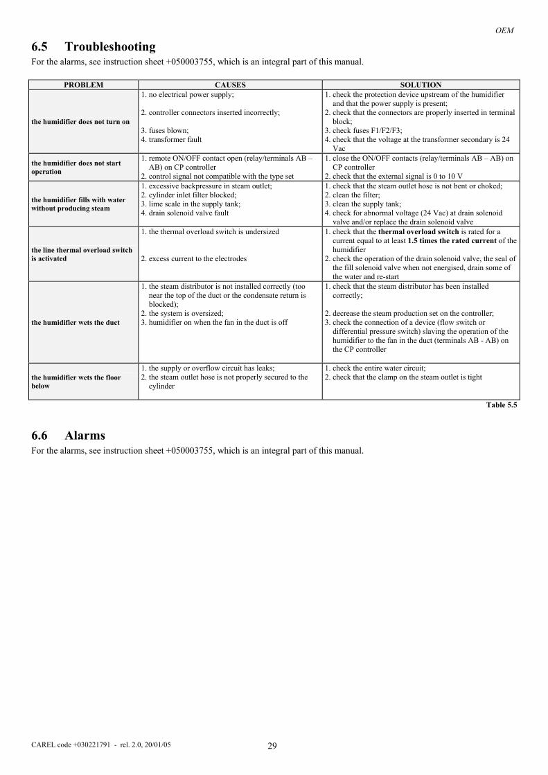
6.5 Troubleshooting For the alarms, see instruction sheet +050003755, which is an integral part of this manual.
PROBLEM CAUSES SOLUTION
the humidifier does not turn on
1. no electrical power supply; 2. controller connectors inserted incorrectly; 3. fuses blown; 4. transformer fault
1. check the protection device upstream of the humidifier and that the power supply is present;
2. check that the connectors are properly inserted in terminal block;
3. check fuses F1/F2/F3; 4. check that the voltage at the transformer secondary is 24
Vac
the humidifier does not start operation
1. remote ON/OFF contact open (relay/terminals AB – AB) on CP controller
2. control signal not compatible with the type set
1. close the ON/OFF contacts (relay/terminals AB – AB) on CP controller
2. check that the external signal is 0 to 10 V
the humidifier fills with water without producing steam
1. excessive backpressure in steam outlet; 2. cylinder inlet filter blocked; 3. lime scale in the supply tank; 4. drain solenoid valve fault
1. check that the steam outlet hose is not bent or choked; 2. clean the filter; 3. clean the supply tank; 4. check for abnormal voltage (24 Vac) at drain solenoid
valve and/or replace the drain solenoid valve
the line thermal overload switch is activated
1. the thermal overload switch is undersized 2. excess current to the electrodes
1. check that the thermal overload switch is rated for a current equal to at least 1.5 times the rated current of the humidifier
2. check the operation of the drain solenoid valve, the seal of the fill solenoid valve when not energised, drain some of the water and re-start
the humidifier wets the duct
1. the steam distributor is not installed correctly (too near the top of the duct or the condensate return is blocked);
2. the system is oversized; 3. humidifier on when the fan in the duct is off
1. check that the steam distributor has been installed correctly;
2. decrease the steam production set on the controller; 3. check the connection of a device (flow switch or
differential pressure switch) slaving the operation of the humidifier to the fan in the duct (terminals AB - AB) on the CP controller
the humidifier wets the floor below
1. the supply or overflow circuit has leaks; 2. the steam outlet hose is not properly secured to the
cylinder
1. check the entire water circuit; 2. check that the clamp on the steam outlet is tight
Table 5.5
6.6 Alarms For the alarms, see instruction sheet +050003755, which is an integral part of this manual.

OEM
CAREL code +030221791 - rel. 2.0, 20/01/05 30
7. OPERATING PRINCIPLE, CONTROL AND OTHER FUNCTIONS 7.1 Operating principle In an electrode humidifier the production of humidity is obtained inside a cylinder (boiler) containing water that is heated to and then held at boiling temperature. The water that evaporates over time is automatically replaced with water from the mains supply. The heat required to boil the water is produced by passing an electrical current through the cylinder. This is done by connecting the electrodes immersed inside the cylinder to the mains power supply. The quantity of current that initially flows depends greatly on the type of water supplied from the mains. Normally, a recently-started cylinder has low current; nonetheless, over time the quantity of salts inside the water increases (evaporation in fact does not carry the salts with it). This allows the level of current required by the unit to provide the quantity of steam requested to be reached. In stable operating conditions, the level of production required is automatically achieved using the water level control on the cylinder. This is in fact reflected in higher or lower levels of current. The salts introduced by the automatic refilling of the water are partly deposited as lime scale inside the cylinder, contributing to the progressive depletion of the cylinder, and partly remain dissolved in the water. To avoid excessive accumulation of salts, a quantity of water is periodically and automatically drained and then replaced with fresh water.
7.2 Control principles The range of humidifiers includes the following control options.
7.2.1 ON/OFF control - CP controllers The action is all or nothing, activated by an external contact that consequently determines the control set point and differential.
7.2.2 Proportional control - CP controllers The steam production (quantity per hour) is proportional to the value of a signal Y coming from an external device; the type of signal can be selected – programmed via RS485 – from the following standards: 0 to 10 V (default), 2 to 10 V, 0 to 1 V. The entire range is indicated as BP (proportional band). The maximum production, Pmax, corresponding to the maximum value of the Y external signal, and can be programmed between 20% and 100% of the rated humidifier value (dip A3-A4). The minimum production, Pmin, is set to 20% of the rated value, with an activation hysteresis, given by the value hy, corresponding to 2% of the entire BP interval of the external signal Y.
PRODUZIONEDI VAPORE
hy
OFF ON
Pmax
P min hy
YBP
Fig. 6.2.2.1

OEM
CAREL code +030221791 - rel. 2.0, 20/01/05 31
8. TECHNICAL SPECIFICATIONS MODEL KUETR* KUESR* KUES1* KUET1* KUES2* KUET2* KUES3* KUET3* KUET4* steam flow-rate (kg/h) 1.5 to 3 1.5 to 3 1.5 to 3 1.5 to 3 5 5 to 8 9 10 to 15 25 to 45 connection (dia. mm) 22/30 30 40 outlet pressure limits (Pa) 0 to 500 0 to 500 0 to 600 0 to 2300 supply water connection G¾ temperature limits (°C) 1 to 40 pressure limits (MPa) 0.1…0.8 (1 to 8 bar, 14.5 to 116 psi) hardness limits (°fH) ≤ 40 instant flow-rate (l/min) 0.6 1.2 4 range of conductivity (µS/cm) 125 to 1250 drain water connection (φ mm) 32 40 typical temperature (°C) ≤100 instant flow-rate (l/min) ~ 4 22.5 environmental conditions ambient operating temperature (°C) 1 to 50 ambient operating humidity (% rH) 10 to 60 ( 90 non-condensing) storage temperature (°C) -10T70 storage humidity (% rH) 5 to 95 index of protection (CEI EN 60529) IP00 electronic controller (see CP controller instruction sheet) type CP1*, CP2*, CP3*, CP4* CP3* auxiliary voltage / frequency (V - Hz) 24VAC(-15% to +10%) / 50 - 60Hz maximum auxiliary power (VA) 30 signal inputs input impedance for 0 to 10 V, 2 to 10 V, 0 to 1 V signals: 15 kΩ Electrical specifications: see the instruction sheet for the CP controller, code +050003755 MODEL KUETR* KUESR* KUES1* KUET1* KUES2* KUET2* KUES3* KUET3* KUET4* Power 1.5 3 1.5 3 1.5 3 1.5 3 5 5 8 9 10 15 25 35 45 rated power supply voltage: 208V-1~N code U
instant steam production (1) (kg/h) 1.5 3 1.5 3 1.5 3 1.5 3 5 8.7 power input at rated voltage (kW) 1.12 2.25 1.12 2.25 1.12 2.25 1.12 2.25 3.75 6.52 rated power supply voltage: 230V-1~N code D
instant steam production (1) (kg/h) 5 9 power input at rated voltage (kW) 3.75 6.75 rated power supply voltage: 208V-3~ code W
instant steam production (1) (kg/h) 5 8 10 15 25 35 power input at rated voltage (kW) 3.75 6.00 7.50 11.25 18.75 26.25 rated power supply voltage: 230V-3~ code K
instant steam production (1) (kg/h) 5 8 10 15 25 35 power input at rated voltage (kW) 3.75 6.00 7.50 11.25 18.75 26.25 rated power supply voltage: 400V-3~ code L
instant steam production (1) (kg/h) 5 8 10 15 25 35 45 power input at rated voltage (kW) 3.75 6.00 7.50 11.25 18.75 26.25 33.75rated power supply voltage: 460V-3~ code M
instant steam production (1) (kg/h) 5 8 10 15 25 35 45 power input at rated voltage (kW) 3.75 6.00 7.50 11.25 18.75 26.25 33.75rated power supply voltage: 575V-3~ code N
instant steam production (1) (kg/h) 5 8 10 15 25 35 45 power input at rated voltage (kW) 3.75 6.00 7.50 11.25 18.75 26.25 33.75 CAREL reserves the right to modify or change its products without prior notice.

Notes:____________________________________________________________________________________________________
_________________________________________________________________________________________________________
_________________________________________________________________________________________________________
_________________________________________________________________________________________________________
_________________________________________________________________________________________________________
_________________________________________________________________________________________________________
_________________________________________________________________________________________________________
_________________________________________________________________________________________________________
_________________________________________________________________________________________________________
_________________________________________________________________________________________________________
_________________________________________________________________________________________________________
_________________________________________________________________________________________________________
_________________________________________________________________________________________________________
_________________________________________________________________________________________________________
_________________________________________________________________________________________________________
_________________________________________________________________________________________________________
_________________________________________________________________________________________________________
_________________________________________________________________________________________________________
_________________________________________________________________________________________________________
_________________________________________________________________________________________________________
_________________________________________________________________________________________________________
_________________________________________________________________________________________________________
_________________________________________________________________________________________________________
_________________________________________________________________________________________________________
_________________________________________________________________________________________________________
_________________________________________________________________________________________________________
_________________________________________________________________________________________________________
_________________________________________________________________________________________________________
_________________________________________________________________________________________________________
_________________________________________________________________________________________________________
_________________________________________________________________________________________________________
_________________________________________________________________________________________________________
_________________________________________________________________________________________________________
_________________________________________________________________________________________________________
_________________________________________________________________________________________________________
_________________________________________________________________________________________________________
_________________________________________________________________________________________________________
_________________________________________________________________________________________________________
_________________________________________________________________________________________________________
_________________________________________________________________________________________________________
_________________________________________________________________________________________________________
_________________________________________________________________________________________________________
_________________________________________________________________________________________________________


CAREL S.p.A. Via dell’Industria, 11 - 35020 Brugine - Padova (Italy) Tel. (+39) 049.9716611 Fax (+39) 049.9716600 http://www.CAREL.com - e-mail: [email protected]
Agency:
CA
REL
cod
e +0
3022
1791
- re
l. 2.
0, 2
0/01
/05