of 1 nasa · 1 nasa goddard space flight center ... we describe some basics of gps relative...
TRANSCRIPT
1 Source of Acquisition NASA Goddard Space Flight Center 1
AAS 07-235
SINGLE-FREQUENCY GPS RELATIVE NAVIGATION IN A NIGH IONOSPHERE ORBITAL ENVIRONMENT
Patrick R. Conrad,* Bo J. Naaszt
The Global Positioning System (GPS) provides a convenient source for space vehicle relative navigation measurements, especially for low Earth orbit formation flying and autonomous rendezvous mission concepts. For single-frequency GPS receivers, ionospheric path de- lay can be a significant error source if not properly mitigated. In particular) ionospheric effects are known to cape significant radial position error bias and add dramatically to relative state estima- tion error if the onboard navigation software does not force the use of measurements from common or shared GPS space vehicles. We present results from GPS navigation simulations for a pair of space vehicles flying in formation and using GPS pseudorange measure- ments to perform absolute and relative orbit determination. With careful measurement selection techniques we show relative state esti- mation accuracy to less than 20 cm with standard GPS pseudorange processing, and less than 10 cm with single-differenced pseudorange processing.
INTRODUCTION
Spacecraft formation flying is widely acknowledged as an enabling technology for space- bcased astronomy and Earth remote sensing. While a few missions have demonstrated autonomous relative navigation and cooperative sensing,' none as of yet have demonstrated the continuous, cooperative) and precise control of the relative geometry of multiple vehicles, henceforth referred to as Precision Formation Flying (PFF) . A mission to demonstrate this core capability to perform PFF is required to help allay the associated risks. Such a mission would likely be highly cost-constrained, but still highly risk averse (New n/Iillenium Program Space Technology missions, for example are designated as Class C, requiring a high standard on parts selection). As a result of this low-cost, low-risk environment, a PFF demonstration would probably occur in Low Earth Orbit (LEO), and with a minimal set of high-TRL sensors and actuators necessary to exercise a formation flying system architecture (including onboard navigation, communication, and control) that is scalable to future missions.
*Cooperative Education Student, NASA Goddard Space Flight Center; Currently Undergradu- ate Student, Cornel1 University, School of Applied and Engineering Physics, Ithaca, Ny, 14850, prc234T-cornell. edu
iAerospace Engineer, NASA Goddard Space Flight Center, Flight Dynamics Analysis Branch, Code 595, Greenbelt, MD 20771, (301) 286-3819, bo .naaszATnasa. gov
1
https://ntrs.nasa.gov/search.jsp?R=20070014901 2018-06-28T02:56:54+00:00Z
The scope of this paper is limited to the scalable onboard navigation system, and the minimal sensor set necessary to demonstrate that system. In particular, we investigate a navigation architecture applicable to a PFF demonstration mission, and consisting of high Technology Readiness Level (TRL) software and components. We explore the relative navigation accuracy of the system, and its sensitivity to realistic space environment effects such as ionospheric path delay. We study: 1) the impact of measurement selection, and the need to include measurements from shared GPS transmitters only; 2) the tradeoff between dual-inertial$ state filter estimation and estimation of one inertial and one relative state; 3) the expected performance of the proposed PFF onboard navigation system. In the next section, we describe some basics of GPS relative navigation and ionospheric path delay effects, and introduce the proposed onboard navigation system. We then describe our simulation enviroment and filter settings. Finally we describe the simulations we use to explore these issues and their results.
PFF RELATIVE NAVIGATION
While advanced GPS is an ideal relative navigation sensor for LEO, and some Highly Eccentric Orbit (HEO) and Geosynchronous Earth Orbit (G,EO) applications, extremely low signal levels and poor geometry make it an insufficient sensor for applications far from Earth, such as proposed PFF missions at Sun-Earth Lagrange points. Proposed precision formation flying missions such as Terrestrial Planet Finder (TPF) will require non-GPS- based inter-spacecraft range and bearing measurements, combined in a sequential estimation filter. These relative navigation sensors are available or currently under development ,2 but probably not feasible for a highly cost-constrained PFF demonstration. We assume a PFF demonstration mission in LEO that employs mature flight software, the GPS Enhanced Onboard Navigation System (GEONS),3 and measurements provided by a GPS receiver and inter-spacecraft communication device, both with considerable flight heritage (the General Dynamics (GD) Viceroy and Multi-Mode Transceiver (MMT), respectively). We assume GEONS processes a minimal set of measurements, including inter-spacecraft range and GPS pseudorange.
GPS Measurement Processing
GPS receivers make ideal sensors for spacecraft relative navigation in low Earth orbit ap- plications such as formation flying and rendezvous and d~cking."~ Fast -acquisition and low-power signal acquisition and tracking capabilities7 and improved Carrier Differential GPS (CDGPS) algorithms' are even extending the applicability of GPS to relative naviga- tion tasks well above the GPS constellation.
In LEO application, various receivers employing carrier differential GPS techniques have demonstrated (in software and hardware simulations) 3D RMS relative navigation accura- cies ranging from 1 mm to 50 cm in position, and 0.5 mm/s to 50 cm/s in ~eloci ty .~ CDGPS navigation to this level of accuracy requires a receiver capable of generating carrier-phase measurements with integer ambiguities in double-differenced observations. Synchronization of measurements to GPS integer seconds is also required to allow direct differencing of mea- surements between receivers. Finally, high fidelity dynamics models can improve velocity state estimates considerably.
'Throughout this paper we refer to "inertial" and ::relative" state estimation. The reader should interpret "inertial" state or "absolute" state to mean the position and velocity of a given space vehicle with respect to an Earth Centered Inertial (ECI) reference system, and 'kelative" state to mean the position and velocity of a space vehicle with respect to another vehicle in the formation, but still expressed in the ECI basis.
2
CDGPS holds great promise for improved relative navigation accuracy, but cost limita- tions and our goal of demonstrating PFF system-level cap regimes require the use of high TRL components. While the the measurements necessary for CDGPS, such a techni with the device. Furt capability alre carrier- smoo t he
Ionospheric Path Delay
The ionosphere introduces a bias into GPS measurements. The speed of light in the iono- sphere is slowed proportionally to the number of electrons between the transmitting GPS
ing satellite. This increases the time delay between tra messages, adding a bias which increases the pseudoran
low Earth orbit. This effect is dependent upon the length of the signal path through the ionosphere and the density along that path. The effect increases with decreasing altitude. When the biases from several transmitting satellites are added together in a GPS receiver, the resulting computed position will include a significant bias, usually in the radial direction. In a GPS based navigation solution, the ionospheric delay may be the dominant source of error.
GPS ionospheric biases can be removed entirely from solutions with several processing techniques. Because the signal delay is frequency dependent, the most effective technique is a dual-frequency receiver. These receivers use both the L1 and L2 bands to calculate the ionospheric delay and subtract it from the measured pseudoranges before processing them. Unfortunately, flight-proven dual-frequency receivers are expensive and much less common than their simpler counterparts. Even without a dual band receiver; the local satellite can attempt to estimate the ionospheric bias of each transmitter as part of the navigation filter. Alternatively, the system could use a code-carrier combination to eliminate a significant portion of the error.5
If two satellites are in close formation, the distance between them is almost negligible compared to the total path length of the GPS signal. Since the paths are quite similar, the ionospheric biases are quite close. Differencing techniques exploit this to determine accurate relative positions by considering the difference between the observed pseudoranges of two local satellites and a single GPS transmitter. These techniques facilitate the removal of ionospheric effects from the relative position estimate, but they cannot improve the inertial position estimate. Fortunately, in many formation flying missions only the relative solution needs a high degree of precision, so differencing techniques provide all the ionospheric cor- rections required. The absolute position is still accurate to within tens of meters, and this is often acceptable.
Even if differencing s are not available, the similar common GPS transmitter c with standard Coarse/Ac
tter. Therefore, the indi
urements from a single GPS transmitter “common:’ GPS satellite. If only one of ular GPS satellite at a given epoch, we
3
will call it an unshared or uncommon GPS transmitter. Unshared transmitting satellites do not benefit from this type of bias canceling, and large errors can be introduced to the relative position estimate which are far above acceptable‘ limits for a PFF mission.
Onboard Navigation System
We use the GPS Enhanced Onboard Navigation System (GEONS)3 to complete this naviga- tion analysis. GEONS is flight software developed at NASA GSFC to provide high-accuracy orbit and time information onboard the spacecraft. The navigation algorithms consist of the following core components: 1) a U-D Factorized Extended Kalman Filter (EKF) with physically representative models; 2) a high fidelity state dynamics model; and 3) enhanced Fault Detection, Isolation and Recovery (FDIR) capabilities.
The GEONS EKF includes models for a variety of measurements, including: GPS pseudorange, Doppler, and carrier phase; inter-spacecraft crosslink range, Doppler, and line- of-sight vector; Tracking and Data Relay Satellite System (TDRSS) forward-link Doppler; ground-station-to-satellite range and Doppler; celestial objects measurements (line-of-sight vectors, SUR elevatio? angle, near-to-far- and near-to-near-body pseudoangles); and point solution position measurements.
High-fidelity state dynamics models in GEONS include non-spherical Earth (JGM-2 up to order 30 and degree 30) and Lunar (LPIOOK) gravity models, point mass gravitation models for the sun and planets, atmospheric drag and solar radiation pressure models, and external accelerations expressed in a variety of convenient coordinate systems. In addition to absolute and relative position and velocity states, drag and solar radiation pressure, time bias and drift, unmodeled acceleration, ionospheric path delay, and numerous measurement biases can be estimated in the filter.
In addition to EKF state vector and covariance estimation capabilities, a number of other features are available in GEONS. These features include: “cold-start” filter initial- ization; automatic FDIR capabilities (including measurement editing, filter convergence monitoring, comparison of filter solution with other available solutions, position and veloc- ity covariance tests, etc); real-time state vector propagation; and maneuver targetting via a Lambert algorithm.
The various measurement and filter options described above are either included or not included in the desired flight GEONS configuration through build-time options, making the system highly reconfigurable and scdable to a variety of missions. Onboard processor capabilities and the availability of highly accurate sensors are the only limiting factors in the performance of the system. Since the number of vehicles estimated and the measurement inputs are flexible in GEONS, this system is fully scalable to future PFF formations.
RELATIVE NAVIGATION SIMULATION
.
Throughout the simulations, we present navigation results for a test formation consisting of a pair of satellites in 420 km, circular, sun-synchronous orbits. The relative motion is a safety ellipse” , with 300 x 600 x 300 m periodic elliptical motion in the rotating spacecraft- fixed Radial, In-track, Cross-track (RIC) frame. The truth ephemerides are propagated with the Satellite Tool Kit (STK) HPOP propagator, using the JGM2 gravity model of degree and order 70. Atmospheric drag and solar radiation pressure are not included to isolate the influence of the ionosphere. We create GPS measurements from those truth ephemerides using a simulator designed with GEONS called Measurement Data Simulation
4
Program (Datsim). Finally, we present these simulated measurements to a GEONS filter and compare the estimated states against the original truth ephemerides. Except where otherwise noted, the measurement simulation settings are listed in Table 1 and the GEONS filter settings are listed in Table 2. The simulations are approximately six hours long.
'
Table 1 : Datsim measurement simulation parameters
Clock PSD coefficient3 ho Clock PSD coefficients h-2
2.0 x 10⁻¹⁹ 2.0 x 10⁻²⁰
GPS Pseudorange white noise GPS Broadcast ephemeris errors
0.5 m 2.0 m
(TCXO), with Power Spectral Density (PSD) coefficients as defined in Ref 11.
. Table 2: Base GEONS filter parameters
Gravity model JGM2 30 x 30 Velocity noise variance rate 1 x m2/s3 Clock bias variance rate 0.009 m2/s Clock drift variance rate 0.03553 m2/s3 Initial state position component error 150 m Initial state velocity component error 0.15 m/s Initial position covariance 1 x lo6 m Initial velocity covariance 1.0 m/s Filter update frequency 1 Hz
SIMULATION RESULTS
In several sets of simulations, we investigate the effect of the ionosphere and quantify the accuracy of possible sensor packages. We begin by considering a method of measurement selection to reduce the effect of the ionosphere on relative navigation accuracy. Then we consider the sensitivity of relative estimation to relative process noise. Next we estimate the accuracy of the sensor package after the inclusion of a ranging crosslink. Finally, we consider the possible improvement in accuracy from single differencing GPS measurements.
Measurement Selection Effects
We wish to explore how quickly ionospheric biases from unshared GPS transmitters will contaminate the relative estimate of a simple C/A GPS filter. To study the effect of uncom- mon satellites, we introduce a sorting step before presenting the raw measurements to the filter. In this step, we limit pseudorange measurements per epoch to a fixed 9 transmitters for each receiving satellite and sort the measurements to force the two receiving satellites t o have a specified number of shared transmitters. To avoid introducing error based on the
5
geometry of the chosen GPS satellites, we sort based on the transmitting GPS satellite's Pseudo-Random Noise (PRN) code. This technique provides a somewhat uniform geometric distribution of transmitters for both local vehicles. Finally, we present these measurements to a GEONS filter and compare the estimated solutions to the original truth data.
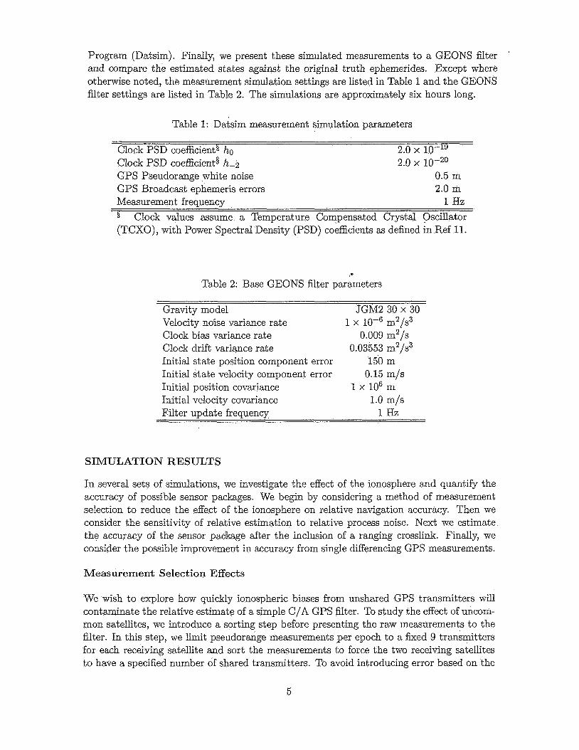
We test two types of sorting parameters to consider the effects of shared GPS satellites. The first sorting method includes a11 available satellites, shared and unshared, up to 9 and typically 8-9 total for each local satellite. We specify the number of transmitters shared between the two local satellites, and vary that number between 4 and 9. In the second set of simulations an identical group of transmitting GPS satellites is assigned to both vehicles, and the total number of GPS transmitters is varied between 3 and 9. By comparing these two sets of results, we hope to learn how quickly unshared transmitters contaminate the relative solution. Multiple trials of each case are simulated to vary the noise seeds on the measurements and the initial state errors. Figure 1 shows the results of these simulations. As we expect, both sets of solutions have increased accuracy when more common satelIites are included. The effect of the unshared transmitters is clearly detrimental. When there are frequently not enough measurements to solve for GPS point solutions, the mean number of satellites is around 4 or less, the relative solution drastically suffers. By simply removing the unshared transmitters, we can increase the accuracy of the relative position estimate dramatically. This is a simple improvement we can make to the navigation solution, which significantly increases the accuracy of the relative estimate.
- E 0' lo3
. . . . . . . . . . . . . . . . . . . . . . . . . . . . u
4 5 fi 7
Mean Number of Common Transmitters
Figure 1: Relative position estimation errors for varying numbers of shared and unshared GPS transmitters. The "all available" category includes all visible GPS satellites including up to nine total. The %ommon only" category includes only GPS transmitters shared by the two local satellites.
Crosslink Range Measurements
We would like to make an improvement to the sensor package and introduce a ranging cross link. Such sensors are readily available, and so do not preclude our criteria to avoid unproven
6
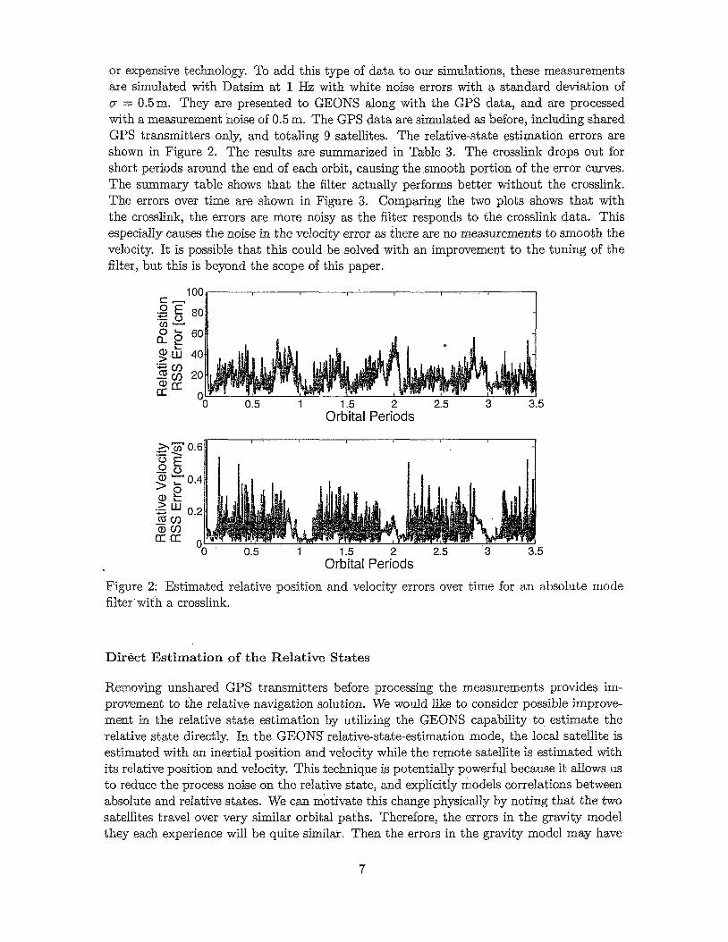
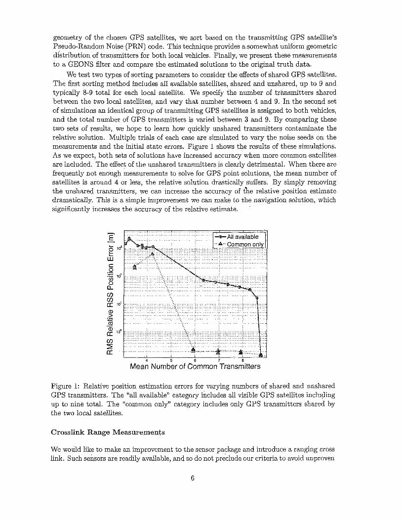
or expensive technology. To add this type of data to our simulations, these measurements are simulated with Datsim at 1 Hz with white noise errors with a standard deviation of CT = 0.5m. They are presented to GEONS along with the GPS data, and are processed with a measurement noise of 0.5 m. The GPS data are simulated as before, including shared GPS transmitters only, and totaling 9 satellites. The relative-state estimation errors are shown in Figure 2. The results are summarized in Table 3. The crosslink drops out for short periods around the end of each orbit, causing the smooth portion of the error curves. The summary table shows that the filter actually performs better without the crosslink. The errors over time are shown in Figure 3. Comparing the two plots shows that with the crosslink, the errors are more noisy as the filter responds to the crosslink data. This especially causes the noise in the velocity error as there are no measurements to smooth the velocity. It is possible that this could be solved with an improvement to the tuning of the filter, but this is beyond the scope of this paper.
Orbital Periods
Orbital Periods Figure 2: Estimated relative position and velocity errors over time for an absolute mode filter with a crosslink.
Direct Estimation of the Relative States
Removing unshared GPS transmitters before processing the measurements provides im- provement to the relative navigation solution. We would like to consider possible improve- ment in the relative state estimation by utilizing the GEONS capability to estimate the relative state directly. In the GEONS relative-state-estimation mode, the local satellite is estimated with an inertial position and velocity while the remote satellite is estimated with its relative position and velocity. This technique is potentially powerful because it allows us to reduce the process noise on the relative state, and explicitly models correlations between absolute and relative states. We can motivate this change physically by noting that the two satellites travel over very similar orbital paths. Therefore, the errors in the gravity model they each experience will be quite similar. Then the errors in the gravity model may have
7
Orbital Periods 5
Orbital Periods e
Figure 3: Estimated relative position and velocity errors over time for an absolute mode filter without a crosslink.
a dramatic effect on the absolute position of the formation, but should not change the rel- ative positions as much. If we included atmospheric drag or solar radiation pressure, those forces should be quite similar on both satellites because of the close proximity of identical satellites. Therefore? those forces should motivate this change just as the gravity model does.
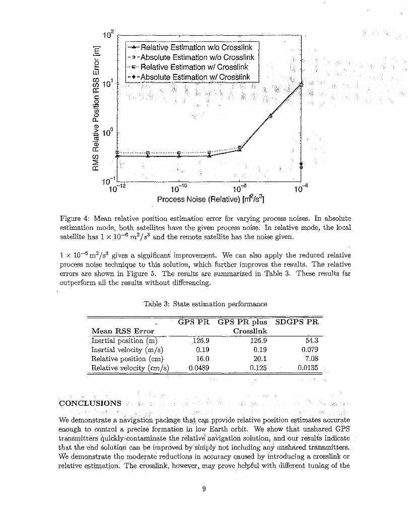
To investigate the effect of the value of the relative process noise, we begin with a simulation performed earlier with only 9 shared transmitters. We then change the relative process noise over many orders of magnitude. The results are shown in Figure 4. As we expect, the graph shows that the relative posi€ion accuracy increases as the process noise is decreased and the filter is forced to smooth the relative solution more than previously. It is also not surprising that the solution degrades slightly once the process noise is too small because the filter no longer applies the necessary innovation to relative state estimation. The best solution, however, remains the absolute estimate, by a small margin. Without a crosslink, the best tuning of the relative filter is with velocity noise variance rates of 1 x m2/s3. The best accuracies are listed in Table 3.
Single Differencing
Before concluding this investigation? we consider the accuracy resulting from single dif- ferencing techniques. These methods are more complicated to implement, but provide a more refined method for processing GPS data even for the limited measurement set we consider here. We expect that the results of single differencing will be a significant increase in accuracy. GEONS already supports the Single-Differenced GPS (SDGPS) measurement type, so it is a simple matter to activate the feature, and indicate that the differenced mea- surement noise is -& times the Pseudo-range (PR) Standard Deviation (a) of 0.5m. This simulation does not include a crosslink. The initial simulation with large process noises of
8
Process Noise (Relative) [rn'/sS
Figure 4: Mean relative position estimation error for varying process noises. In absolute estimation mode, both satellites have the given process noise. In relative mode, the local satellite has 1 x m2/s3 and the remote satellite has the noise given.
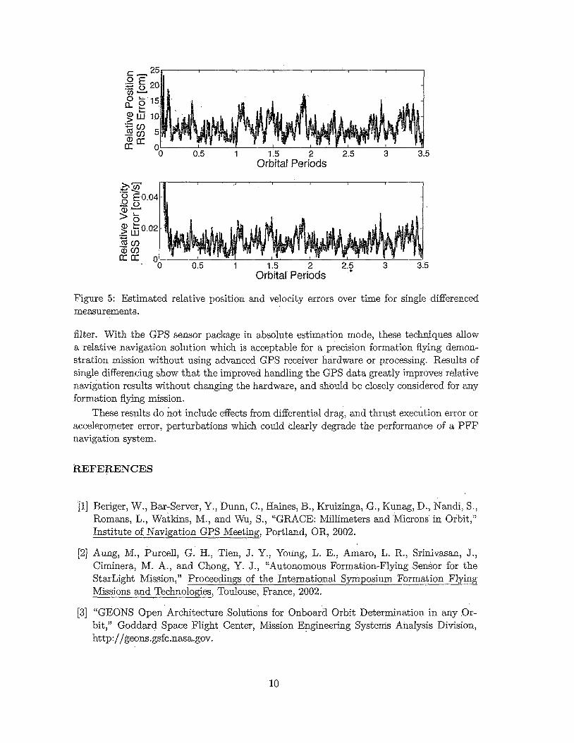
1 x 10⁻⁶m2/s3 gives a significant improvement. We can also apply the reduced relative process noise technique to this solution, which further improves the results. The relative errors are shown in Figure 5. The results are summarized in Table 3. These results far outperform aJ.I the results without differencing.
Table 3: State estimation performance
- GPS PR GPS PR plus SDGPS PR Mean RSS Error Crosslink
Inertial velocity (m/s) 0.19 0.19 0.079 Relative position (cm) 16.0 20.1 7.08
roducing a crosslink or t h different tuning of the
9
Orbital Periods
Orbital Periods
Figure 5: Estimated relative position and velocity errors over time for single differenced measurements.
filter. With the GPS sensor package in absolute estimation mode, these techniques allow a relative navigation solution which is acceptable for a precision formation flying demon- stration mission without using advanced GPS receiver hardware or processing. Results of single differencing show that the improved handling the GPS data greatly improves relative navigation results without changing the hardware, and should be closeIy considered for any formation flying mission.
These results do not include effects from differential drag, and thrust execution error or accelerometer error, perturbations which could clearly degrade the performance of a PFF navigation system.
REFERENCES
[l] Beriger, W., Bar-Server, Y., Diinn, C., Haines, B., Kruizinga, G., Kunag, D., Nandi, S., Romans, L., TVatkins, M., and Wu, S., “GRACE: N’illimeters and Microns in Orbit,” Institute of Navigation GPS Meeting, Portland, OR, 2002.
[2] Aung, M., Purcell, G. H., Tien, J. Y., Young, L. E., Amaro, L. R., Srinivasan, J., Ciminera, Nl. A., and Chong, Y. J., “Autonomous Formation-Flying Sensor for the StarLight A/lission,” Missions and Technologies, Toulouse, France, 2002.
[3] “GEONS Open Architecture Solutions for Onboard Orbit Determination in any Or- bit,” Goddard Space Flight Center, Mission Engineering Systems Analysis Division, http://geons.gsfc.nnsa.gov.
10
[4] Busse, F., How, J., and Simpson, J., ”Demonstration of Adaptive Extended Kalman Filter for Low Earth Orbit Formation Estimation Using CDGPS ,” Institute of Navigation GPS Meeting, Portland, OR, 2002.
[5] Leung, S. and Montenbruck, 0 ., “Real-Time Navigation of Formation-Flying Space- craft Using Global-Positioning-System Measurements,” Journal of Guidance, Control, and Dynamics, Vol. 28, No. 2, 2005, pp. 226-235.
[6] Wolfe, J. D. and Speyer, J. L., “Effective Estimation of Relative Positions in Orbit Using Differential Carrier-Phase GPS,” 2004 AIAA Guidance, Navigation, and Control Conference and Exhibit, Providence, RI, 2004, AIAA 2004-4777.
[7] Winternitz, L., Moreau, M., Boegner, Jr., G. J., and Sirotzky, S., “Navigator GPS Receiver for Fast Acquisition and Weak Signal Space Applications,” Institute of Navigation GNSS Meeting, Long Beach, CA, 2004.
[8] Mohiuddin, S. and Psiaki, M. L., “Satellite Relative Navigation Using Carrier-Phase Differential GPS with Integer Ambiguities,” 2005 AIAA Guidance, Navigation, and Control Conference and Exhibit, San Francisco, CA, 2005, AIAA-2005-6054. .
[9] Zyla, L. V. and Montez, M. N., !‘Use of two GPS receivers in order to perform space vehicle orbital rendezvous,” Proceedings of the ION GPS-93, Salt Lake City, Utah, 1993, pp. 301-312.
[lo] Naasz, B. J., “Safety Ellipse Motion with Coarse Sun Angle Optimization,” Flight Mechanics Symposium, Goddard Space Flight Center, Greenbelt, WID, 2005.
Ell] Brown, R. 6. and Hwang, P. Y , C., Introduction to Random Signals and Applied Kalman Filtering, Third Edition, John Wiley and Sons, New York, NY, 1997.
. ACRONYMS AND ABBREVIATIONS
C/A Coarse/Acquisition
CDGPS Carrier Differential GPS
Datsim Measurement Data Simulation Program
ECI Earth Centered Inertial
EKF Extended Kalman Filter
FDIR Fault Detection, Isolation and Recovery
GD General Dynamics
GEO Geosynchronous Earth Orbit
GEONS GPS Enhanced Onboard Navigation System
GPS Global Positioning System
HE0 Highly Eccentric Orbit
11
HPOP High Precision Orbit Propagator
JGM2 Joint Gravity Model version 2
LEO Low Earth Orbit
LPlOOK Lunar Prospector lOOx 100 Gravity NIodel
MMT Nlulti-Mode Transceiver
PFF Precision Formation Flying
PR Pseudo-range
PRN Pseudo-Random Noise
PSD Power Spectral Density
RIC rotating spacecraft-fixed Radial, In-track, Cross-track
RSS Root Sum Square
CJ Standard Deviation
SDGPS Single-Differenced GPS
STK Satellite Tool Kit
TCXO Temperature Compensated Crystal Oscillator
TDRSS Tracking and Data Relay Satellite System
TPF Terrestrial Planet Finder
TRL Technology Readiness Level
12