of - austin seven clubs' association - a7ca of the adjustments and attentions described i~ the...
TRANSCRIPT

:; n,; ,a:'<f~iI!Iff"~"I"""", '1>j, "<",it,
f'"
, HANDBOOK
\
OF.
i~
,I.
If,
If
!""
I~:I!)'
,Iti,11
It!
PUBLICATION No. lO95A.
..
PRICE. ONE SHILLING.
THE
AUSTIN MOTOR 'CO. LTD.LONGBRIDGE :: BIRMINGHAM
,

_. .,
HANDBOOKOF
li
PRICE - ONE SHILLING27th EDITION.
THE AUSTIN MOTOR CO. LTD.LONGBRIDGE - BIRMINGHAMTelePhonn,Telegmm" "SPEEDILY, NORTHFIELD."
PRIORY 2101-2120
Code, BENTLEY'S
LONDON ~HOWROOMS& REPAIR DEPOT FOR 7& 10 H.P.:
479-483, Oxford' Street, W.!.TehPhone,
\1AYFAIR 7620 to 7638.Telegram, ,
"AUSTINETTE,WESDO, LONDON,"
AND
HOLLAND . PARK HALLHOLLAND PARK AVENUE, W,ll
,..
I.
In "f"m~ 10IkM Boo' 1095 Api"", quo/, th, nn"""
e""no ,. '.oc..o

~A
fi Foreword.
I"
THE information contained in this Handbook is intended
only to guide and assist owners or drivers of Austin cars to
preserve the car in its proper satisfactory running condition.
This publication must not be considered as a complete manual.The handbook does not in any manner vary or extend the liability
of the Company, which is limited to the Warranty issued withthe car. Where no infonnation is given for a particular adjustment,
it may be regarded as one which the average owner would entrust
to a garage. When the occasion for adjustments of this character
arises, the owner should seek the aid of the local Austin dealer
whose address will be found in the list supplied with the
car. Both owner and dealer are encouraged to call upon the Service
Department of the Company for advice, whether ';pon the manage-
ment of the car, the effecting of adjustment, or methods of repair.
Owners need not suppose that they will have to apply all the
attentions given in this book, but careful notice should be taken of
the chapters dealing with 'maintenance.
~
Two additional publications give lists and illustrations of all the
parts, and their prices, respectively, and the owner should find these
books helpful for reference.
Many of the adjustments and attentions described i~ the following
pages are included in the" Schedule of Charges for Repairs." Th;
Company is confident that owners will find it to 'heir own henefit
to make the fullest use of this .tandard price <cpair and maintenance.ervice, which it i. a function of all Au.tin dealers to offer.
IMPORTANT,-See special note at end of book, withreference to accessories and equipment not manufacturedby the Austin Motor Co., Ltd.
'-34.
2
,
>
CONTENTSAMMETER READINGS
ATTENTIONS, Do;Iy
Weekly
Monthly.. Oc",;on.1
BATTERY. Th,
BODYWORK, Ca" of . .BRAKES. Ad;u,';ng th,BRAKE GEAR, Luh,;c",;on of ..
BRAKES, R,.hn;ngCAR, Con"ol of th,
F eatue," of th, ..Th,N,w
CARBURETTER. Th,.. . ..Adi",tm,nt, ,tc. "
" .. "Sport,'CLUTCH. Lub,;,,';on of M,dum;,m
COMBUSTION CHAMBER, CIean;ng ..COOLING SYSTEMDYNAMO, Th,ELECTRICAL EQUIPMENT, Th,ENGINE, Luh,;"t;on of
Star';ng th,
"
FANFUEL SYSTEMFUSE, Act;on of th,GEARBOX, Lub,;,,';on ofGREASE GUN, How '0 use th,
HOOD (Ca" of)HUBS (Fmnt .nd Rw) Lub,;"t;on ofIGNITION, T;m;ng . .
.. Sy,t,m,Th,INFLATING SEAT INTERIORSLAMPS, Ca, ofLUBRICATION CHARTLUBRICANTS, Cho;" of
PETROL PUMPREAR AXLE, Luh';,,';on ofROAD SPRINGS. Lub,;"t;on ofRUNNING ADJUSTMENTSSHOCK ABSORBERS, Adiu,tm,nt of ..STEERING. Adiustm,n' ofSTEERING GEAR, Lub';,,';on ofTOOLS, Suppl;,dTYRES, Th,UNIVERSAL JOINT. Luh,;,,';on ofVALVE TAPPETS, Ad;u,tm,nt ofWHEEL, Cbang;n. . . .WIRING, lIlu"'.';on of
..
3
PAGE461414151547635439561067
1819223851324444358
40,601646383461
40,4131276243423516394051595838652639511250
\
I
~
}
lr
,The hand lever and pedal each apply hrakes to all four wheel.
which carry 3.50 X 19 Dunlop tyres.
The Austin Seilen is particularly suitable for the woman driver.It requires little physical effort to drive and control, and for thatreason its use enables her to do shopping calls without fatigue, visither friends, attend social and other functions, or make excursionsor trips in any direction in any weather. For the same reasonsbusiness men find it an excellent vehicle, and commercial travellersand others whose occupation compels frequent calls over an extendedarea, have in the little car an embodiment of all they require. Coilscan be made in places where trains, trams and 'buses are infrequent.
In large establishments where the instant use of a car is of vitalimportance in cases of emergency, such as sudden illness or accident,the Seven has been installed as a "tender," and in addition to itssuperiority over large unwieldy cars for short runs, has proved areal time and money saver.
As 40 miles per gallon is the average petrol consumption, thecost of transit is below the cost of fares on any public conveyance, andin this particular the Austin Seven has no rival..
Its speed, economy, reliability and road-holding qualities havebeen admitted beyond dispute.
Thousands of motorists have had their first experiences on a"Seven," thousands more will follow them.
Having successfully passed through a decade of severe use and trial,it has emerged a really successful and popular favourite; and itssplendid qualities are internationally recognized.
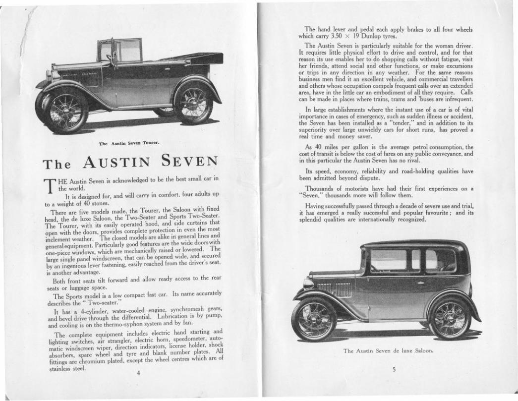
The A...t" Soven Toom.
The AUSTIN SEVEN
THE Austin Seven is acknowledged to be the best small car inthe world.
It is designed for, and will carry in comfort, four adults upto a weight of 40 stones.
There are five models made, the Tourer, the Saloon with fixedhead. the de luxe Saloon, the Two-Seater and Sports Two-Seater.The Tourer, with its easily operated hood, and side curtains thatopen with the doors, provides complete protection in even the mostinclement weather. The closed models are alike in general lines andgeneral equipment. Particularly good features are the wide doors withone-piece windows, which are mechanically raised or lowered. Thelarge single panel windscreen, that can be opened wide, and securedby an ingenious lever fastening, easily reached from the driver's seat,is another advantage.
Both front seats tilt forward and allow ready access to the rearseats or luggage space.
The Sports model is a Iow compact fast car. Its name accuratelydescribes the " Two-seater."
It has a 4-cylinder, water-cooled engine, synchromesh gears,and bevel drive through the differential. Lubrication is by pump,alld cooling is on the thermo-syphon system and by fan.
The complete equipment includes electric hand starting andlighting switches, air strangler, electric horn, speedometer,auto-matic windscreen wiper, direction indicators, license holder, shockabsorbers, spare wheel and tyre and blank number plates. Allfittings are chromium plated, except the wheel centres which are ofstainless steel.
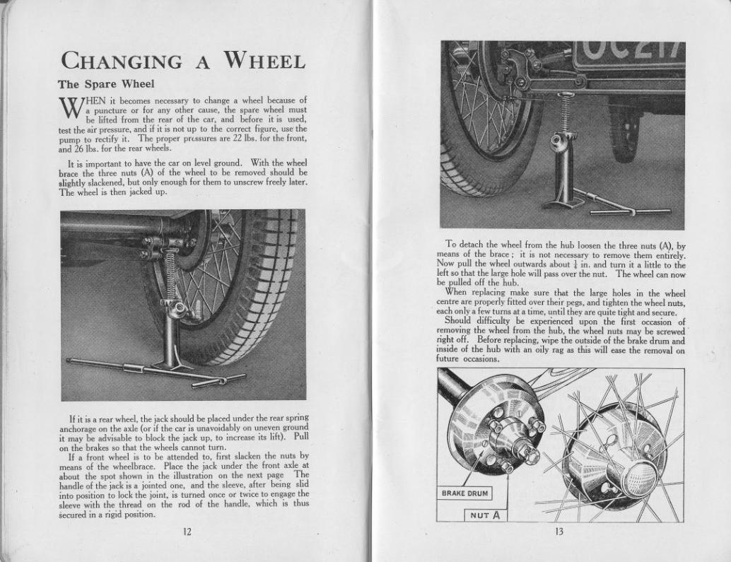
The Austin Seven de luxe Saloon.
54
...j-

DIMENSIONS
ENGINE
STARTER. .
CLUTCH.
GEARBOX.
!I.
REARAXLE. .
SPRINGS.
1'1
STEERING
FRONT AXLE
BRAKES.
WHEELS .
CONTROLS .
PETROL TANK.
LIGHTING
BODYWORK.
WORKMANSHIP
INSURANCE .
The NEW CARITS LEADING FEATURES IF YOU ARE NOT FAMILIAR WITH AUSTIN CARS
PLEASE READ TInS HANDBOOKCAREFULLY.
GIVE the new car a general examination to see that all is inorder. Check the tool kit as list on page 65.Before running, see the car is snpplied with fuel and water,
that the engine and gearbox have the necessary quantities of oil,that the battery contains the proper amount of acid-see sectionsLubrication and Electrical Equipment.
Cars delivered by road are ready for running; on those trans-ported by rail or overseas the engine may have become stiff throughthe gumming of oil on the pistons. A little petrol injected into thecylinders will free them. Remove the sparking plugs, pour in athimbleful of petrol, wait a minute, replace the plugs and turn theengine over a few times by means of the starting handle.
There is no oil, fuel or water in cars crated for overseas and thebatteries are empty and uncharged.
. Full "', I,ngth. 9 ft. 11in. (3.023mm.); Full "" width(om doo, h,ndl,,) 4 ft. 3 in. (1.295mm.); Wheelb"" 6 ft.9 in. (2,057 mm.); T",k, 3 ft. 4 in. (1,016 mm.)G,ound d""n" 8. in. (222 mm,).
. Fou,.cylind", w,t".cool,d. detachAbl,h"d.Bo", 2.2in. (56mm.) }7475 RAC t
. 78hS k 3
.(76 )
. c.c.. ' . ." mg" .p.tto e, m. mm.
B"k, bo,",.pow,,; 12 ,t 2600 "p.m.Ignition; Coi!.Oilciteul,tion; by pump.Cooling; Th"mMypbon with film "di,to' ,nd I,n.Roll" cr,nkh,ft beatings.
. EI,ct,i",!.
. . Singl,.pl,t,.
. Fou, speodsfo,w"d. ,nd , ,ov""; Syncbmm"h,ng'gc-m'nt fo, thi,d ,nd top ,p,od,. 2nd,3,d and top speedg"'"beingin const,ntmd ,nsu" ,iI,nt running. "hos; 22.94,13.85.8.73.and5.25to I; B,ll b",ing' thmugbout.
.-flo,ting. with diff""nti,1 and tO'qu' tube.Ball beatings and thmsts th,ougbout. Final d,i" by shaft,nd 'pi,,1 b",!.
. !.elliptic cmss,p,ing in Imnt.Quart"elliptics at "".Shockab,o,b", at, litted to fmnt and "".
. WOtmand wheel,b,ving p,ovisionlOtt,king up w",.
. Fo,g,d, I "ction.
On all fou, wheels; oasily adjustable. Both hand ,nd foolb"k" op",t, on all fom wheel,.
. Special wi" detachabl" fitt,d with Dunlop (3.50-19) tyt",One 'pa" wh,d witb ty".
. BallchIDg' ,peed ge" lovet,andb"k, leve,.mount,d centrally.Ga, and ignition contmll,vets moun!odon tb, stwing wheeland dip and ,witcb 1°' h"dlights on column und" ,twingwhee!. Foot accd",to, i, ,Iso pmvid,d.
5 g,llon t,nk at "". Fuel supply by p,tml pump.
By "oa,.d,i"n dyn'mo. witb "cumulato," and dimm".
. Two buck" "at, lOtdriv" ,nd p""ng". both b,ing hing,dto ,llow oasy,nt"nce to th, "" s"t, R", "'I to "'tty two,dults or th", child"n. Ample tool "commodation undet",ts. Spa" wheeland tyt, c",iod on balk of "'t. On tamingmodd, hood. ,ingle piece se",n ,nd lull sid, ",eens (tho"ovet th, doo," op,n with tbem). EI,ct,ic ham. and ,p,do.m,t", di"ction indicato,",,utom,ticwindse",n wiper.d,ivingmitto' and licen" hold",
AND MATERIALS. Austin qu,lity.
Speci,lln,u"nce h" been a",ng,d ,t £10 I,. 3d. pOt,nnumm'pt fo, """ g"'g,d within 10mil" 01town, witb , popu.latiou meeding 250.000lor which ca," th, ,nnu,1 p",niumis £11 3s. 9d.
1. A"oJ""Ot P,d,12. B"" P,",13. C1o"h P,d,1+. H,odb"" Lm,5. Ch,og, Speed Lm,6, Pmo1 G,ug,,. Oil p""u," G,uge
!'!The Instrument Board.
8. D"h L,mp 15. Horn Buuoo9, Sp"dom"" 16. Pull Out S,"u" Sw'"h
to. Amm"" 17. I,oit'oo Coo'm1 L,v"11. W,rn'og Light 18. D,p 'od Sw'"h12. Swit,hbo"d 19. Di""ioo Iod'wo,13. 1'°"'00 K,y. 20. Smogl"
14. C"bu"""CootmIL,m 21. W'odso",ow'p"Sw'"h7
6

r.1
1
Difficulty in Starting
\Difficulty in starting may be caused either through sucking too
much petrol into the cylinders,or too little. When starting with thethrottle all but closed. a strong suction takes effect on the pilot jet.
I Ifpetrol is passingthrough the carburetter the suction can generallybe heard. If the engine fails to start and there is a good deal ofpetrol overflowingfrom the carburetter it is almost certain that themixture getting into the cylinder is too rich. The throttle shouldthen he opened half-way to reduce the suction. On firing. theengine will race away, and the throttle should be almost closed.If the engine does not fire closethe throttle entirely, and try again.After a stop in hot weather, failure of the engine to start is morelikelyto be due to a too rich mixture than one too lean, and oneshould stop the engine by the switch only after quite dosing thethrottle. Re-start the enginewith the throttle closed.
If the starter does not turn the engine over readily, depress thedutch pedal beforeswitchingon. This will lessenthe starting load,and so help the starter to turn the engine at higher speed.
If after the foregoingmeasures have been carried out the enginefails to start, the reason will probably be due to faulty ignition orcarburation.
IGNITION: Fint examinethe wires and see that the sparkingplugs are connected. Then test the gap of the plug points by meansof the thick end of the gauge provided in the tool kit. If the pointsare dirty, dean them beforereplacingthe plug.
CARBURATION: The slow running jet may be stopped upor a m.un jet choked. Blowthem out with a tyre pump.
The engine .bould never be allowed to ran at higb .peechfor the first 300 miles.
Starting the EngineMake sure that the change speed lever is in neutral position and
the hand hrake on.
Set the engine control levers at the top of the steering wheel-Gas-open about t in. Ignition-almost fully advanced.
Give the engine a few turns with the starting handle to make surethat the crankshaft is free (pushing the handle in to engage fully withthe starting nut. before turning it). The ignition key is turnedto the right to switch on the ignition and the charging and lightin~switch is turned to '!Summer ! Charge" or "Winter Full C:' Pullout the wire on the instrumentboard to close the carburetter airinlet, and pull out the switch tooperate the starter. Be sure torelease the air shutter wire afterthe engjne has started. Do notallow the engine to race when firststarting up, as time must be allowedfor the oil to circulate and lubricatevarious bearings.
When the engine is running, seethat the starting handle is not hang-
ing down. It should he replaced in a horizontal position at "9 0'dock."There is a' catch which will secure it in its proper place there on theoff-side of the car.
~Never leave the ignition switch on for any lengthy period while
the engine is not running. The warning lamp on the switch boardwill remind you of this.
R 9

i
I
CONTROL OF THE CARSetting of Control Levers
AFTER having started the engine. see that the starter handleis in a horizontal position. if it is left hanging down it permitswet and damp to work into the bearing of the starter handle shaft
and causes rust. Keep the ignition lever in the advanced position;should the engine commence to "rumble" or run roughly. retardthe lever. but advance it again as soon as the load on the engineis lessened. The "gas" lever should be set generally for slow run-ning and the speed of the car controlled by the accelerator peda\.
Changing Speeds.
':/
Ilil
'if
To engage first gear, push out theclutch and move the gear lever intothe first speed position.
Sometimes it may happen thatwhen the clutch is let in again. thereis no apparent drive from the engine.That is because there has been noproper engagement of the gears.Therefore, push out the clutch again.and it will almost certainly be foundthat the lever can then' be movedso as to give the proper gear engage-ment without using any force.
Start on first speed. accelerate to about 8 m.p.h.. push out theclutch. move the lever to neutral. let in the clutch. pause. push outthe clutch and move the lever to the second speed position.
This is the process known as double declutching.In moving from second to third speed. the synchromesh action
takes place. Accelerate to about 18 m.p.h.. declutch, release theacc elerator, move the lever to neutral and continue the movementof the lever steadily into the third speed position. and let in the clutchgently.
Third and top gears being synchromesh it is not necessary to domore than declutch and move the lever steadily into the positiondesired. It assists the change from top to third if the acceleratoris held down while the change is made.
Always change gear early on a hill: never allow the engine tolabour in any gear and expect it to pick up speed on changing into alower one when the car has nearly stopped. Do not persist inattempting to drive the car uphill in top gear when the speed fallsbelow 18 m.p.h.-change down. If the car has been driven back bythe reverse gear. wait until it is stationary before engaging a forwardspeed. Do not engage the reverse gear when the car is travellingforward. Serious damage to the gears will be the result.
Keep the foot off the clutch pedal except in heavy traffic. Eventhen. do not allow the weight of the foot to be taken by the peda\.The slipping of the clutch caused by this practice heats and wears itbadly.
I '~\I~))Jf'.,??~I}~
- 10
.,I
I
(
I
When descend-a long hill. orbefore commen-cing a steep des-cent. engage one ofthe lower gears,and keep thethrottle c I 0 sed.The engine willthen help to re-tard the speed ofthe car. W henusing the brake.keep the clutch in.disengaging it atthe last moment ifstopping the car.
The driving seat of the Austin Seven is adjustable for positionand this convenience should be taken advantage of so as to obtainthe greatest comfort.
~
11
7
!
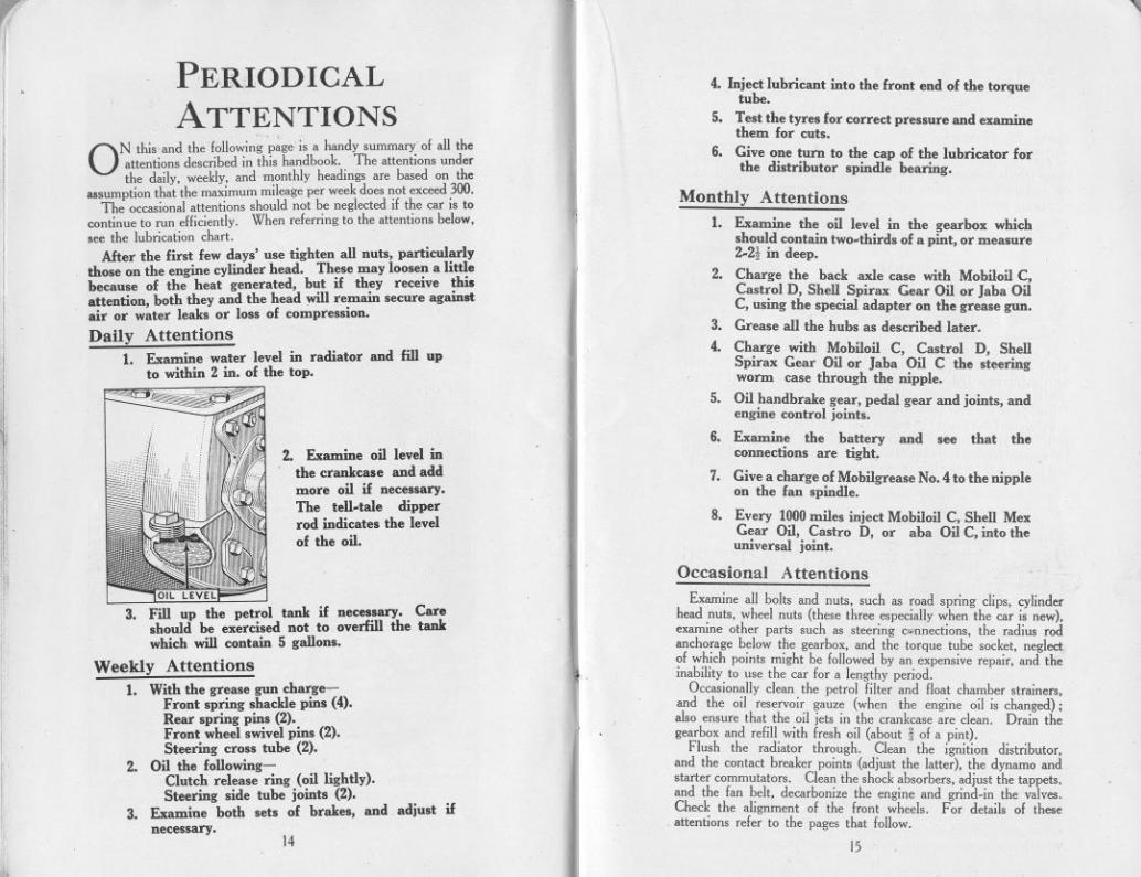
I CHANGING A WHEELThe Spare Wheel
WHEN it becomes necessary to change a wheel because ofa puncture or for any other cause, the spare wheel mustbe lifted from the rear of the car, and before it is used,
test the air pressure, and if it is not up to the correct figure, us~ thepump to rectify it. The proper pressures are 22 Ibs. for the/ront,and 26 Ibs. for the rear wheels.
It is important to have the car on level ground. With the wheelbrace the three nuts (A) of the wheel to be removed should beslightly slackened, but only enough for them to unscrew freely later.The wheel is then jacked up. ,
"'
[
',1","
'I'
il
i
"
~
'':i,
To detach the wheel from the hub loosen the three nuts (A), bymeans of the brace; it is not necessary to remove them entirely.Now pull the wheel outwards about! in. and turn it a little to theleft so that the large hole will pass over the nut. The wheel can nowbe pulled off the hub.
When replacing make sure that the large holes in the wheelcentre are properly fitted over their pegs, and tighten the wheel nuts,each only a few turns at a time, until they are quite tight and secure.
Should difficulty be experienced upon the first occasion ofremoving the wheel from the hub, the wheel nuts may be screwed"right off. Before replacing, wipe the outside of the brake drum andinside of the hub with an oily rag as this will ease the removal onfuture occasions.
II
If it is a rear wheel, the jack should be placed under the rear springanchorage on the axle (or if the car is unavoidably on uneven groundit may be advisable to block the jack up, to increase its lift). Pullon the brakes so that the wheels cannot turn.
If a front wheel is to be attended to, first slacken the nuts bymeans of the wheelbrace. Place the jack under the front axle atabout the spot shown in the illustration on the next page Thehandle of the jack is a jointed one, and the sleeve, after being slidinto position to lock the joint, is turned once or twice to engage thesleeve with the thread on the rod of tbe handle, which is thussecured in a rigid position. NUT A
12 13
,
JII"'"
lI
~
PERIODICALATTENTIONS
4. Inject lubricant into the front end of the torquetube.
5. Test the tyres for correct pressure and examinethem for cuts.
6. Give one turn to the cap of the lubricator forthe distributor spindle bearing.ON this and the"following'p~geis a handy summary'of all the
attentions described in this handbook. The attentions underthe daily. weekly. and monthly headings are based on the
assumptionthat the maximummileageper weekdoesnot exceed300.The occasionalattentions should not be neglectedif the car is to
continue to run efficiently. When referringto the attentions below.see the lubrication chart.
After tbe first few days' use tighten all nuts, particularlythose on the engjne cylinder head. These may loosen a littlehecause of the heat generated, but if they receive thisattention, both they and the head will remain secure againstair or water leaks or loss of compression.
Daily Attentions1. Examine water level in radiator and fill up
to within 2 in. of the top.
'11
'11;
2. Examine oil level inthe crankcase and addmore oil if necessary.The tell.tale dipperrod indicates the levelof the oil.
Monthly Attentions
1. Examine the oil level in the gearbox whichshould contain two-thirds of a pint, or measure2.2t in deep.
2. Charge the back axle case with Mobiloil C,Castrol D, Shell Spirax Gear Oil or Jaba OilC, using the special adapter on the grease gun.
3. Grease all the hubs as described later.
4. Charge with Mobiloil C, Castrol D, ShellSpirax Gear Oil or Jaba Oil C the steeringworm case through the nipple.
5. Oil handbrake gear, pedal gear and joints, andengine control joints.
6. Examine the battery and see that theconnections are tight".
7. Give a charge of MobiJgrease No. 4 to the nippleon the fan spindle.
8. Every 1000miles inject Mobiloil C, Shell MexGear Oil, Castro D, or aba Oil C, into theuniversal joint.
Occasional AttentionsOIL LEVEL
3. Fill up the petrol tank if necessary. Careshould be exercised not to overfill the tankwhich will contain 5 gallons.
Weekly Attentions
1. With the grease gun charg ,Front spring shackle pins (4).Rear spring pins (2).Front wheel swivel pins (2).Steering cross tube (2).
2. Oil the following-Clutch release ring (oil lightly).Steering side tube joints (2).
3. Examine both sets of brakes, andnecessary.
adjust if
Examine all bolts and nuts. such as road spring clips. cylinderhead nuts. wheel nuts (these three especially when the car is new).examine other parts such as steering c(.mnections. the radius rodanchorage below tlie gearbox. and the torque tube socket. neglectof which points might be followod by an expensive repair. and theinability to use the car for a lengthy period.
Occasionally clean the petrol filter and float chamber strainers.and the oil reservoir gauze (when the engine oil is changed) ;also ensure that the oil jets in the crankcase are clean. Drain thegearbox and refill with fresh oil (about i of a pint).
Flush the radiator through. Clean the ignition distrihutor.and the contact breaker points (adjust the latter). the dynamo andstarter commutators. Clean the shock absorbers. adjust the tappets.and the fan belt. decarbonize the engine and grind-in the valves.Check the alignment of the front wheels. For details of theseattentions refer to the pages that follow.
14 15

If
THE FUEL SYSTEMTHE PETROL PUMP
How it Works.Petrol is draw", from the tank at the rear by means of a petrol
pump which delivers the fuel in the correct quantity demanded bythe carburetter-no more and no less-an automatic mechanismaccurately governs the operation.
CARBUrTTER PU~P ~K END~
pC1-J .
By revolving shaft (C) the eccentric (H) will lift rocker arm (D),which is pivoted at (E) and which pulls the pull rod (F), togetherwith diaphragm (A) downward against spring pressure (C), thuscreating a vacuum in pump chamber (M).
Fuel from the rear tank will enter at (J) into sediment bowl (K)and through filter gauge (L) and section valve (N) into pump chamber(M). On the return stroke, spring pressure (C) pushes diaphragm(A) upward forcing fuel from chamber (M) through pressure valve (0)and opening (P) into the carburetter.
OUT
il!
G
K(
'"" " TH' OIIAI"TAPT'T""""""-'."," ""OT",.,,"'"" """, v"w
D
s~~W
When the carburetter bowl is filled the float in the float chamberwillshut off the inlet needle valve;thus creatinga pressure in pumpchamber (M). this pressure will hold diaphragm (A) downwardagainst the spring pressure (C) and it will remain in this positionuntil the carburetter requiresfurther fueland the needle valveopens.
16
/The rocker arm (D) is in two pieces, the outer one operatmg theinner by making contact with pin (R) and the movement of theeccentric (H) is absorbed by this "break" when fuel is not required.
Spring (S) is merely for the purpose of keeping rocker arm (D)in constant contact with eccentric (H) to eliminate noise.
SERVICE HINTS.Service on the A.c. Fuel Pump is available through authorized
A.c. Service Stations, who are prepared with parts and fixtures forrepairing all types of pumps. There are some service operationson this fuel pump that can, if necessary, be done without referringto the service station and these are given below. In some instancestrouble is attributed to the fuel pump which in reality is caused bysome other conditions. These should be carefully checked to avoidthe needless replacement of fuel pumps.Lack of Fuel at the Carburetter.
Check the following instructions;-Petrol Tank empty.-Refill.Leaky tubing or connectiono.-Replace tubing and tighten all
pipe connections at the fuel pump and petrol tank.Bent or kinked tubing.-Replace tubing.Head loooe. -Tighten the thumb nut, making certain that the cork
gasket lies flat in its seat and is not broken.Dirty otrainer,-Remove the head and clean the gauze. Make
certain that the gauze is,properly replaced and the cork gasket isproperly seated when reassembling.
Loose valve plug (one projects through filter gauze, other iounderneath).- Tighten the valve plug securely, replacing tbevalve plug gasket if necessary.
Dirty or warped valves.-Remove the valve plugs and valves.Wash the valves in petrol. If damaged or warped, replace them.Examine valve seats to make certain there are no irregularitieswhich prevent the proper seating of the valves. Place valve invalve chamber with the polished side facing the seating. Makecertain that each valve lies flat on its seat and is not left standingon edge. Reassemble valve plug and spring, making certain thatthe spring is around the lower stem of the valve plug properly.Use a new gasket under the valve plug if necessary.
Leakage of Fuel at the Diaphragm.Loose cover screwo.- Tighten the cover screws alternately and
securely. CAUTION: Do not dismantle the pump body.NOTE.-Sometimes there appears to be a leak at the diaphragm,
whereas the leak 'actually exists at one of the pipe fittings and thefuel has run down to the pump to the diaphragm flange, appearingto originate there.
Flooding of Carburetter.Carburetter needle valve not oeating.-check carburetter forproper adjustment.
IMPORTANT.-Do not attempt to disassemble the fuel pumpfurther than described above, because it is absolutely necessary touse a special fixture in reassembling the pump when once takenapart. When the above remedies do not correct the condition,replace with a new fuel pump sending the old fuel pump to yournearest A.C. service station.
17

.
!i11
THE 'V' TYPEZENITH CARBURETTERBrief Working Description.
FROM the tank the petrol passes via the pump through theUnion (A), the filter and the needle seating into the lIoatehamber. The petrol rises and when reaching a certain
predetermined height will cause the lIoat to push the needle on to itsseating, thus regulating the petrol lIow.
The lIoat chamber contains the main jet (I), (see illustration onnext page) compensating jet (2), compensating well (3), and slowrunning jet (4). The petrol will then lIow through the main andcompensating jets and also rise in the compensating well.
'11
11
I'II
11
I'~
J D
"'1,'1
A
',,'I
"
r
i'1'I
!iliA-Union. E-Stops<:rew. H-Petrolooon<ctor.D-Holding-down.crows. F-AirreguJating.crew. J-Wuhen.
From the jets the petrol flows along two separate channels into acommon channel in the emulsion block (5), whieh is attaehed to thefloat chamber.
The petrol in the compensating well is in direct communicationwith the air and with the emulsion block. Consequently, all thepetrol from the jets and well is now centred in one channel in theemulsion block. This ehannelleads to a nozzle (6), which projectsdirectly into the choke tube.
Starting.To obtain an easy start from cold the control on the dash operating
the air strangler should be fully extended and with the throttle alsoelosed the engine should be cranked over a few times by pressing
18
'l,
I
I
the self-starter. Then open the throttle an eighth of an inch or soon the hand control, and open the strangler slightly. If the engine isthen switched on it should start readily and continue to run.
When the engine is definitely running the strangler should begradually released until it is in the 'full open' position.
Adjustments.
The carburetter is delivered with the. setting that has boen foundby extensive experimental work to be most suitable. Consequently.very little adjustment to the carburetter is needed.. Indeed the userwill find that a greater service will be obtained from the carburetterif the various screws etc., are only moved when absolutely necessary,
On those occasions, however, when an adjustment is advisable(after a new car has been' run in' an adjustment of the slow runningis sometimes necessary) or when the carburetter requires cleaning.the following procedure should be observed.
Slow Running.Slow running is adjusted by means of the stop screw (E) and the
air regulating screw (F).
D
D-Holding-down s<:rew.
K-SqUArod ond to form jet koy.
I-Main jo'. 2-<:Ompon..tin. jet.
3-<:Ompon..ting won. 4-Slow-runnin. iot.5-Emul.ion block. 6-Nmlo.
2
6 4
19

- ,
Ill'""
~:
:~J
M
'it~I~"
',,~,
Dismantling the Carburetter.The bowl of the carburetter can be removed by taking out the
holding down screws (D). The hand should be placed underneaththe bowl during this operation for when the screws are removed thebowl will drop into the hand, and any petrol that is contained in thebowl can then be emptied back into the tank. On turning the bowlupside down the float will slide out and reveal the main and com-pensating jets at the bottom of the bowl (see illustration).
"Leaded" Fuels.
The advent of "leaded" fuels (petrols containing a small pro-portion of tetraethyllead) on the British market has led to a numberof queries concerning their use and effect in engines.
Provided that the same reasonable attention is given to valves andadjustments as ,.jth ordinary petrols there ,.jll be no trouble whenusing these fuels.
The appearance of the valves when running on "leaded" fuel,differs from that associated with ordinary petrol, but this is a wellrecognized fact to which no significance should be attached.
The deposit from such fuels can be removed by "scrubbing" thevalves and their seats ,.jth a stiff wire brush, of the type used forcleaning files (a file card), aher which the valves can then be "groundin" in the normal manner.
We would recommend this method of cleaning for all valveswhether they have operated with "leaded" or ordinary fuels as iteliminates the possibility of leaving small amounts of deposit on thevalve seats which tend to cause damage. or prolong the "grinding in"process.
Speed of Tick-over.The top screw (E) determines the speed of the slow running,
i.e., it adjusts the opening position of the throttle. To increase theslow running speed the stop screw must be turned in a clockwisedirection. A turn in the opposite direction will give a slower tickover.
if
11
11
I
Richness of Slow Running Mixture.The richness of the slow running mixture is adjusted by the air
regulating screw (F). Should the engine refuse to tick over for anylength of time, or stall on deceleration it is a sign that the slowrunning mixture is weak. To overcome this the mixture should bemade richer by turning the regulating screw in a clockwise direction.If the engine is inclined to "hunt" when running slowly the mixtureis too rich and must be weakened by turning the air regulating.crew (F) in an anti-clockMse direction.
1:11
I
I
The Jets;The jets should be removed occasionally and be thoroughly
cleaned. The holding down screws (D) are milled at the end to fitinto the jets. When the bottom end i. placed into the jets a .pannerapplied to the head of the .crew will enable the jets to be removed.
When cleaning the jets it is not advisable to pass anything throughthem that is liable to damage them. The most satisfactory andeffective method is to blow through the jets and wash them in petrol.This will remove any obstruction and leave the jets undamaged.
The sizes of all jets in the Zenith carburetter run in fives and thelarger the number the larger the jet.
~The Filter.
The petrol is filtered on entering the carburetter and the filtershould be cleaned from time to time. To remove the filter unscrewthe petrol connection H and pull the filter out of its chamber. Thefilter gauze can then be thoroughly cleaned with petrol.
When reassembling the filter care must be taken to see that thewashers U)are correctly replaced.
20 21

/['I
,
,I'
A
Petrol is drawn from the tank by a pump and delivered to thecarburetter through union A. passing through the gauze filter andthe needle seating into the float chamber. Referring to diagram 2.it will be seen that the float chamber which is detachable from thecarburetter, holds the main jet I, compensating jet 2, slow runningjet 3, and capacity tube 4.
Petrol flowinginto the floatchamber willcause the float torise, and whenreaching a pre-determined height,will close off theneedle valve there-by regulating thepetrol flow and en-suring a constantlevel in the floatchamber. Passingthrough the mainand compensating 3jets, petrol willrise to the prede-termined level incompensating wellwbich contains thecapacity tube, andis in direct com-
6lI1unication withthe atmosphere attop, and the emulsion block by its bottom outlet. Petrol will flowalong the channel underueath each jet, these uniting in a commonchannel in the emulsion block 5, which is attached to the floatchamber. The outlet from this common channel in the emulsionblock is the nozzle 6 which projects directly into the choke tube.It will be noticed that mixture issuing from the nozzle 6 will strike abar fixed in the choke tube which has the effect of thoroughly~tomising the petrol, and assisting distribution of the charge.
"'-5
The AUSTIN SEVEN"65" SPORTS MODEL
i[II
Zenith 30 VEl CarburetterThis modelis fitted with the Zenith 30 VEl carburetter, of which
a workingdescription is given below.
I1
1\
I1
,I
.1
..11
t~1I:.I'
I
!I'I
The carburetter fitted to tbe 7 h.p. Austin "65" Sports Model isof the downdraught type. It embodies the well-known Zenithprinciples of main and compensating jets. The carburetter ismounted on top of the inlet pipe, because the fundamental advantageof downdraught carburation lies in the fact that fuel is assisted bygravity into the cylinders, instead of having to be lifted against it asis the case of a normal vertical instrument.
Dismantling and Cleaning.There are no moving parts calling for attention in the Zenith
carburetter, consequently it is only necessary to periodically cleanout the instrument to ensure satisfactory operation. The floatchamber bowl can be removed by taking out the holding-downscrews E. The hand should be placed underneath the bowl. so thatwhen the screws are removed, the bowl can be drawn away. Thepetrol may be emptied into the tank, and upon inverting the bowl,the float will slide out, revealing the main and compensating jets.
22 23
a

One of the holding-down screws is squared at the end and can beused to remove the jets. A small screwdriver will remove the slowrunning jet. When cleaning the jets, do not pass anything throughthem that is likely to damage the carefully calibrated orifices. Themost satisfactory and efficient method is to blow through them andwash them in petrol. Swill out with a little petrol any sedimentwhich may have collected in the bottom of the float chamber. It isnot necessary to remove the emulsion block from the float chamber.Unscrew the petrol pipe connection F, and withdraw the filter' gauze.Thoroughly clean this part by washing in petrol. When reassem-bling the filter care must be taken to see that the washers G arecorrectly replaced.
Adjustments.The carburetter is delivered with the setting that has been found
by extensive experimental work to be most suitable for all roundconditions. The complete standard setting is as follows :-
The main jet has the greatest influence at high engine speeds.therefore, alteration to this jet would affect maximum power androad speed.
fI
I1
I[
'I
I
I
~,'
Choke Tube
Main let
Compensating let
Slow Running let
Capacity Tube
Needle Seating
"
j'
t
'.
i
,~I
,:'
i
""I
}!
~!~,1'1"
"
screw C. Turning this part in a clockwise direction increases theengine speed and vice versa. In all cases of difficulty with slowrunning. inspect the slow running jet which may be obstructed,and check the position of the screws Band C. Continued difficultymay be traced to air leaks at inlet pipe joints, etc.. to the valves or tothe ignition system.
Starting from Cold.
Easy starting with the VEl carburetter is assured by an automaticair strangler interconnected with the throttle lever. The strangleris situated in the air intake of the carburetter, and is closed by fullyextending a dashboard control. By means of the interconnectionmechanism, this operation sets the throttle open just the correctamount to ensure an easy start.
... 21,... 95... 40
6021.5
To avoid the possibility of the strangler permitting excessively richmixture passing into the cylinders, a diaphragm has been embodiedin the strangler flap, which will open and permit extra air to enterimmediately the engine fires. The quick opening and closing of thisdiaphragm when the engine is running will cause a buzzing noise,and this will serve to remind the driver that the strangler is still inoperation and should be released. A half-way position is providedon the dashboard control, and it is advisable to run the engine for afew minutes during cold weather with the strangler in this position,before attempting to drive the car away.
Compensating Jet.
This jet has a controlling effect upon acceleration from low speeds,low speed pulling on hills, and quick "get away" from cold.
Failure to Start Readily.
The carburetter having been cleaned and the ignition system,valves, etc., checked over, the following points should be examined.
The Slow Running Jet.Measures the petrol supplied when the engine is idling. Petrol
is drawn through this jet into a channel which has its outlet at thethrottle edge. The petrol is atomised immediately on leaving thejet by air entering the carburetter at the base of the slow runningadjusting screw B. The size of slow running jet should be such thatsmooth regular idling is provided with the slow running screw Bset approximately one complete turn open. This adjustment shouldalways be made with the engine quite hot. The speed at which theengine idles can be regulated by means of the throttle arm stop
:.1
Make sure the air strangler flap closes completely when thedashboard control is operated.
Ascertain that petrol is being supplied to the float chamber by thefuel pump.
Aher lengthy service it may become necessary to readjust the inter-connection between strangler and throttle. Shortening the con-necting link 0 will increase the opening of the throttle.
When cars are used in very hot climates or at high altitudes, aslightly weaker setting than normal is usually required.
2425
,I
r
I TYRES The IGNITIONTHE11
jr
,
SYSTEM
I
T~Erecommendations that follow apply to the LucasIgmtIon eqUIpment.
The set should be examined occasionally and the following
attentions given, only if they seem necessary.
Th~ distributor cover can be removed on springing aside its twosecuring clips. The electrodes "B" and "H" and the inside of thecover are then accessible for cleaning with a dry duster. See that the
carbon brush "A" is
dean and moves freelyin its holder. The con-
tact breaker points canbe similarly cleaned ifrequired. Normally ihegap between the con-tacts will not requireadjustment until a con-siderable mileage hasbeen covered, unlessthe points have burned.The work of re-settingthe points, when thishas occurred, should beleft to a skilled mech-anic. For the normal
~djustment, first turnthe engine by the start-ing handle until thepoints are seen to befully open. Then slack-en the lock-nut (D)with the ignition span-
ner, and turn the screw of the movable point until the gap is setto the thickness of the gauge on the side of the spanner. Thelock-nut must then be re-tightened. (See next page).
Tyre PressureThe minimum pressures to which both front and back tyres
should be inflated are :-
I1
11
li
Iliil;
Shnd"d Ty"Equipm,nt.
InA,cionP""u",.Fmnt.' R",-I 0,2
1
R",.P""ng,'" FullyI.d,n The Distributor
Mod,!.
.,'
2222
Lb.. pe' 'q. in
Should the steering, because of w.ear or other causes, at any timedevelop a tendency to wander or show signs of wobble, this pressureshould be increased. It is important that both front tyres should bekept at the same pressure. In any event there is no reason why thepressure should not be more than the minimum figure given, assome drivers prefer their tyres harder than do others.
As tyres form such a large item in the running costs of a car it isadvisable to give them periodical examination and attention.
A cursory glance should be given daily to see that none of thetyres is unduly slack, and a weekly test with a suitable gauge shouldbe made to verify the pressures. Occasionally examine the tyretreads for cuts; bad cuts should be vulcanized.
Now and again examine the locking nuts which secure the valvesto the rims. These are sometimes loosened when the dust caps areunscrewed. If they are loose, the tube may" creep" and damageto the valve seating, causing a leaky tube, be the result. Therefore,keep the locking nuts tight.
Tyre WearBecause of the turning-in of the wheels towards each other at their
lowest point, it has been found that the front side tyre wears at itsouter edge. The camber of the road tilts the car towards the left,and the tyres are distorted. It is in the action of recovering theircorrect shape, immediately after contact with the road, that theysuffer abrasion, made more damaging because the gritty substancesnow used on tarmac roads accumulate on the near side and the wheelis running in this grit for most of the time it is on the road. Sochange your front wheels over and thus equalize the wear betweenthe tyres. When both tyres have become worn on the outside edge,change the back wheels with the front wheels. Subsequently thetyres can be turned round, bringing the least worn edge to the out-side. If the front tyres should show premature wear at any timesuspect the tracking of the front wheels. Have it checked, to see ifit is correct, and, if necessary, adjusted (see page 58).
2627
3.50x 19W.M.3-19 cim.
2222
2626
Op,n Mod,l,CIo.,d Mod,],
~
'~i
:
1
',.11"," '
I
'I'!!'!
i~l'1
~
'
I1:1:
m.tributo, and Cont"'t B,_ke,.ii'
i!11
. C..bon8,..b.881""0"'.C Cont",...D Lo......
. ReI.lln, O&m.. Con""".G Rot.tin,dI,t.b""
"m.H Ro,.lIn,El"""'., Con"" b".." pI....
I'
, J'

-, I ,
"."""""
they should he replaced. Use only 7 m.m. ruhber covered ignitioncable for all high tension leads.
To make a connection to the distributor or coil terminals, threadthe knurled insulating nut over the lead, bare the end of the cable forabout t of an inch, thread the wire tlirough the brass washer pro-vided, and bend back strands. When the moulded nut is screwedhome, the cable will be securely clamped, and the nut will supportthe cahle, and prevent vibration and fracture.
!
r
Ignition Faults11,
1
1
'I1",I
I
The Coil
When the engine will not fire, or fires erratically, the troublemay arise from the carburetter, or petrol supply and not the ignition.A partially choked jet, an incorrect petrol level, or air leaks intothe induction system may he the faults. Equally, sooted plugs canbe suspected, when dismantling and cleaning them will remedythe trouble. If the battery has run down, or its terminals haveworked loose, quite obviously there will be no spark, and the sameresults can be expected if the distributor electrodes and contactbreaker have been neglected and are dirty.
The coil can be tested by removing the cable from the centresocket on the distributor cover, and holding the end of this cable,about t inch from some metal part of the car, while the ignitionswitch is on and the engine is turned. A strong and regular sparkwill result if the coil is in order. Clean the top of the coil, andensure that its terminals are tight before making this test.
The coil needs no attention apart from keeping the terminalstight and the top clean.
Ignition Switch and Warning Lamp.The key" by means of which the ignition is switched on, should
be withdrawn when the engine is not running; this will ensurethat the battery does not discharge by the current continuing toflow through the coil windings.
The warning lamp on the instrument panel will light when theignition is switched on and the engine is not running. This lamp alsolights when the engine is only idling. Should ihe bulb of thewarning lamp fail, this will not affect the ignition, but it should bereplaced assoon as possible so as to act as a safeguard to the battery.It can be removed from its socket when the small cover plate holdingthe red glass is unscrewed. The replacement bulb should be a 2.5volt .2 amp screw cap type (No. 252 ME.S.) as originally fitted.
Lubrication.The greaser for the distributor shaft should be given one turn
about every 500 miles. Re-pack the greaser with a good qualityhigh melting point grease when necessary. About every 3.000 milesgive the cam the slightest smear of vaseline, and place a single dropof oil on the pivot "r on which the contact breaker works.
To test for short circuits in the low -tension wiring (the cablesfrom the switchboard to coil, coil to distributor, and distrihutor tochassis) which would equally cause irregular running, have theengine turned while the ignition is switched on. and watch theammeter reading. It should rise and fall as the contact breakerpoints close and open. This test will also indicate if the contactbreaker is functioning correctly. If the contacts remain open, ordo not fully close, the reading will not fluctuate.
If the high tension cables from the distributor to the plugs are not. securely attached to the distributor, misfiring may occur. Or,if the rubber insulation on these cables shows signs of perishingand cracking, there may be leakage of the current giving rise to thesame symptoms. Renewing the cables is then the remedy.
...
~
I
,":"
.":-
"f"
I~
~'~
I,I",.:!tI'If'I
'il'!1'I
',
ilill
I Renewing High Tension Leads toDistributor and Coil.
When the high tension cables show sig';s of perishing or cracking"
If after verifying these points, the trouble remains undiscovered,the equipment should be examined and tested by the nearest servicedepot of the makers.
28 29
I'
, J,
""7"
I1'I
'11
11;
Sparking Plugs.
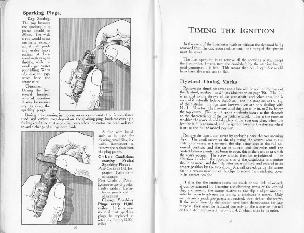
Gap Setting.The gap betweenthe sparking plugpoints should be,018in. Too widea gap would causemisfiring expeci.ally at high speedsand under heavypulling at Iowspeed with an openthrottle, wbile toosmall a gap causespoor idling. Whenadjusting the gap,never bend thecentre wire.
Cleaning.During the firstseveral hundredmiles of operationit may be necess.ary to clean thesparking plugs.
During this running in process, an excess amount of oil is sometimesused, and carbon may deposit on the sparking plug insulator causing afouling condition that soon disappears when the motor has been well runin and a change of oil has been made.
illI,
A fine wire brushsuch as is used forcleaning small files, is auseful instrument toremove the carbon fronithe plug points.0 the r Conditions
causing FouledSparking Plugs:
Poor Grade of Oil. Im-proper Carburetteradjustment.
Poor Grade of Petrol.Excessive use of choke.Faulty cables. Distri-
butor points out ofadjustment.Change Sparking
Plugs every 10.000miles. It is recom.mended that sparkingplugs be repl.aced atintervals of every 10,0))miles.
11"
, ,l30
\
,.
'1
fi
"I
TIMING THE IGNITION
In the event of the distributor (with or without the dynamo) beingremoved from the car, upon replacement, the timing of the ignitionmust be re.set.
The first operation is to remove all the sparking plugs, exceptthe front-No. I-and turn the crankshaft by the starting handleuntil compression is felt. This means that No. I cylinder wouldhave been the next one to fire.
Flywheel Timing Marks
Remove the clutch pit cover and a line will be seen on the back ofthe flywheel, marked I and 4 (see illustration on page 38). The lineis parallel to the throws of the crankshaft, and when this line isvertical it naturally follows that Nos. I and 4 pistons are at the topof their stroke. In this case, however, we are only dealing withNo. I. Now turn the flywheel until this line is 11 in. to 2 in. beforethe top centre. (We cannot quote a definite figure as this dependson the characteristics of the particular engine). This is the positionat which the spark should take place at the sparking plug, when thejgnition is fully advanced, and the ignition lever on the steering wheelis set at the full advanced position.
Remove the distributor cover by springing back the two securingclips. The small screw on the clip fixing the control arm to thedistributor casing is slackened, the clip being kept at the full ad.vanced position, and the casing turned anti.clockwise until thecontact breaker points just begin to open, this is the position at whichthe spark occurs. The screw should then be re.tightened. Thedirection in which the rotating arm of the distributor is pointingshould be noted, and the distributor cover refitted, and secured in itsproper position by the two clips. A small projection on the casingfits in a recesss near one of the clips to secure the distributor coverin its correct position.
If after this the ignition seems too much or too little advanced,it can be adjusted by loosening the clamping screw of the controlclip, and moving the casing relative to the clip a slight amount,anti.clockwise to advance the timing, or clockwise to retard. Onlyan extremely small movement is required, then tighten the screw.If the leads from the distributor have been disconnected for anypurpose, they must be replaced correctly in the sequence markedon the distributor cover, thus :-1,3,4,2, which is the firing order.
31

1
"'I
.r
TheCOOLING SYSTEM
THE cooling of the engine is maintained by a capacious radiatorwhich should be filled, with rain water, if available, up towithin 2 in. of the top of the filler. The capacity of the
radiator, pipes and cylinder jackets is 9-10 pints.I'f
In Cold WeatherI
I1I
1,1:
Care should be takento see that the water isdrained off completely,for,in case of freezing, itwill do harm by lodging'in small spaces and frac-ture of the cylinder blockmay result. In Great
Britain, the climate does not very often call for the cooling system tobe drained, but it is well to err on the right side and take dueprecaution against damage if frost be threatened.
>'1:'..f';7.<:';';'~;';'"""""""""""""""","""'6""",',,,',"""""',', ;<..""""~,,C.!6'~'Z;
' ',',',' N..',','n..',',','N""",'i;.<',',','",'",',,'i' ,'<l6""'6',',', ~h""'b""','~""'~""'i1!""""'N"i""""'i"""1~"?!:':,;.<;"':'.!:':,:,:,:'!<:~,:.:,:t:,:.
I1'1,'
j'if
I~
I
'
'I
'
iJ!
11
<~'
,I
To prevent the gradual formation of deposits in the coolingsystem, with consequent impeding of the circulation, the use ofhard water should be avoided. Rain-water; syphoned from thetop of the barrel where it is clean, should be used. or, failing that.water that has b~n boiled.
Occasionally flush out the water cooling system by opening thedraining cock at the bottom of the raditor, and allowing water torun through; renewing the supply say for five minutes, preferablyby means of a hose.I
""
,,'
li':li
I
I111
Causes of OverheatingOverheating may be attributed to one ur more of the following:Slack fan belt. The belt can be tightened by turning the fanspindle in its bracket after loosening the clamping-nut.Excessive carbon deposit in cylinders. See "Running Adjust-ments."
I:
I
\~
Running with ignition too far retarded.
Using oil of poor quality, or lack of oil in the reservOir."Engine Lubrication."
See
32
(
,
Partial choking of the oil jets. See "Engine Lubrication."
Improper carburetter adjustment, giving a mixture too rich ortoo weak. See "The Carburetter."
.Failure of water to circulate, because of choked radiator tubes.
water leve.! below the tops of the radiator tubes, or loss of waterthrough leakage from connections.
Overcooling is almost as bad as overheating. If the engine tendsto be too cool, use a radiator muff, or possibly, in' winter the fanbelt can be removed without the engine running too hot.
The entire circulating system should be thoroughly flushed outoccasionally. To do this open the drain tap at the bottom, placea hose in the filler. and run fresh water through.
Trouble arising from a damaged radiator generally necessitatesits dismantling and despatch to a repair depot.
~
b
I
33

z~",'I
I I
11,I
"
,I' !iI '
11'IJI11
.11
III
ill',
,IiI.
,
THE
GREASE GUN
LUBRICATIO~.General. . .
THE modem high-speed automobile engine operates at hightemperatures and it is essential that only oils of the highestquality be used, otherwise there is a danger of excessive wear
developing in a relatively short period. Moreover, the use of therecommended oils will eliminate avoidable road delays an~ stoppageswhich are likely to arise when unsuitable lubricants are used.
Even the best oil becomes contaminated with certain impuritiesduring use. In the engine, these may be unburnt fuel, carbon,metallic particles, moisture, etc., and whilst the oil itself does notdeteriorate, the presence of these impurities must reduce its efficiencyas a lubricant and, in time, cause avoidable wear. Oils of the bestquality resist, contamination and consequently wear to the greatestextent, nevertheless it is imperative that the crankcase be drainedperiodically to remove foreign matter, and subsequently refilledwith fresh clean oil.
Drain the crankcase immediately after a run when the oil is warm,and therefore, fluid and thoroughly agitated. It will then carryaway as much of the contamination as possible. Never flush thecrankcase with paraffin-some will remain in the sump to con-taminate the fresh oil, and, in addition, it may loosen, but not entirelyremove, certain deposits which are best left undisturbed until theengine is overhauled.
Rinse gauze filters in petrol and allow to drain before refitting.Do not wipe with fluffy rags.
Oil in the gearbox and back axle becomes contaminated withmetallic particles from the gear teeth and these will cause unnecessarywear of the bearings unless removed. These units should also bedrained periodically and may be flushed with a thin oil. This shouldbe allowed to drain thoroughly, after which the unit should be filledto the correct level with fresh oil.
T HE type of grease gun supplied in the tool kit of all Austincars is known as the Enots "Autolub" gun, and it incorporatesfeatures by which the chassis lubrication of the car is greatly
simplified.
Instead of screwing down the plunger spindle, in order to fill theram of the gun, as in the type previously supplied, once the gun ischarged all that is necessary is to keep pushing the ram of the gunagainst the nipple until the contents are exhausted.
1
r
,
" The ram is automatically returned to its extended position by a
spring. This action creates a vacuum in the gun by means of avalve, and thus refills the high pressure chamber contained in theram.
On the inner rim of the nozzle of the ram, there is a small fibrewasher, which ensures a good leakproof joint between the gun andthe nipple, even though the gun is not applied squarely on to thenipple.
The ram is used for forcing grease through nipples, and theadaptor for lubricating the universal joints with grease and backaxle with oil. For the latter operation, first replace the screw-oncover of the ram, then remove the end cap from the barrel of the gun,pull out the cork plunger by means of the chain, and charge the gun,tQ about three quarters of its capacity. Put the cap of the adaptoron the open end of the gun, and after removing the plugs from theuniversal joints or back axle, place the end of the adaptor into thegreasing holes, and grasping the barrel, push. This will inject alarge quantity of lubricant quickly.
When charging the gun, it should be filled with lubricant to aboutthree quarters of its capacity.
t"
Choice of LubricantsFor the convenience of our customers it has been decided to
recommend officially, in addition to Mobiloil, both Shell and CastrolOils. Each of these oils has the high grade standard of qualityrequired by our Research Department and has proved entirelysatisfactory in actual service. Moreover each of these oils hasadequate distribution at garages and filling stations.
The makes and grades of lubricants recommended are as follows:For Engines.-Mobiloil "BB"; "Triple Shell"; Castrol"XL."For easy starting in cold weather, either Mobiloil AF, or Castrol
AA is helpful. In extreme cold Mobiloil A is useful. T rip!e Shellmay be used in either summer or winter.
Special Lubricants for Sports Models Engines. In summeror winter, Mobiloil 0, Castrol XXL, or Aero Shell.
Torque Tube (front end).-Mobilgrease No. 4, Shell MotorGrease, Castrolease Heavy.
34 35

Always inspect the level of theoil, and add enough to fill tothe correct level before startingon a long journey. The oil levelshould not be allowed to gobelow! inch on the bottomof the dipper rod. It is ad-visable to wipe the dipper rodbefore taking the reading of thelevel, and the reading shouldonly he taken when the engineis not running and the car ison the level ground.
After refilling with fresh oilto the correct level, run the en-
gine for a few moments to check that the oil is circulatingand that the oil pressure gauge reading is correct.
The main bearings of the engine are of the roller type, and theoily vapour in the crankcase is quite sufficient to lubricate these.
The pistons are also lubricated by the oily vapour.Lubrication of the big-ends is effected by catching oil from the
pump-fed jets in pockets on the crankshaft webs.It is advisable to make sure these jets are always clear, and to do
so, the plugs over the jets (A) (see illustration) should be occasionallyremoved and a piece of stiff wire, not above -,\,-in.diameter, insertedthrough the jets. This prevents foreign matter accumulating inthe jets and choking them.
-~
! r!~I For Gearhoxes.-Mobiloil "BB" ; "Triple Shell"; Castrol
"XL."
For Rear Axles and Steering Box.-Mobiloil."C," CastrolD, Shell Spirax Gear Oil; Jaba Oil "c."
Universal Joints.-Mobiloil C, Shell Mex Gear Oil, Castrol D,or Jaba Oil C.
Wheel Huhs.-Mobilgrease No. 4; Shell Motor Grease;Castrolease Heavy.
Grease Gun.-Mobilgrease No. 4; Shell Motor Grease;Castrolease Heavy.
Hand Oilcan.-Gargoyle Velocite Oil D; Wakefield Oilit andShell Household Oil.
For Springs, Rusted Parts or Squeaks.-Voco PenetratingOil; Castrol Penetrating Oil.
It is important to use only high quality lubricants for engine andchassis lubrication. In addition to quoting the recommendedbrands in the above list the correct grades are also specified.
Always purchase lubricants in sealed packages or from brandedcabinets.
Every 2,400-3,000 miles re-move the oil reservoir. Theguaze oil tray will then beaccessible for removal. Scrupu-lously clean the gauze and re-move all dirt from inside thereservoir and replace them.Carefully remake the joint withthe packing washer. coveringhoth sides of it with grease.When tightening up the nutsholding the oil reservoir to thecrankcase, do not pull up onenut tight, but tighten each nutequally, a little at a time. Seethat the drain plug is screwedup tight. then fill the crankcasewith oil to the maximum levelas shown on the dipper rod.About half a gallon will beenough to fill.
'. I!
I,,
11' i,I
11
I
Ii!1
l
i;jll
11],~..I
1
,"'1
'I~!'
The Engine
The recommended lubricants are of the correct quality andviscosity for our units. The matter of the proper grade of oil is veryimportant both in relation to the pump used to circulate the oil, andthe gauge to register the pressure; if a very thick oil were used on acold day, the pump might be strained or the gauge broken. Afterthe first 500-800 miles running, drain the original oil from thereservoir by removing the plug in the bottom, while the engine is hot,and refill with new oil,
I'
'"
1'1,I
LI: 1
After the first re-filling it is advisable to change the oil in theengine entirely after every 1,200 to 1,500 miles running or sooner.
36
,
37

f,r~11
I
:: I, .
11
The Oil Pressure GaugeAn oil pressure gauge which records up to 10 lbs. is now part of
the equipment of the instrument board of the Austin Seven.The dial will probahly record the maximum pressure when the
engine is started from" cold," but as the engine warms up in running.so the oil will become more fluid and the pressure will fall quite low-it may even record only one pound. This, however, is sufficientbecause if the oil is circulating that is all that is necessary.
An obstruction in the oiling system while the car is running wo~ldbe indicated by a sudden rise in the pressure on the gauge.
This unusual difference to the normal registration on the dial.would be quickly noticed, and the cause of the variations ascertainedand set right.
Gearbox
1'1
ill11
III
I!
il
The same grade of oil, as is used for the engine is most suitable forthe gearbox. Do not use thick gear oil, otherwise seizure of bearin!!"may result.
Maintain the oil at the correct level, i.e., bottom' of the filler plughole.
The gearbox should be drained, and refilled to the correct levelafter tbe first 1.000 miles and every 5,000 miles subsequently.Quantity approx. i of a pint.
ill!!
"I~,I !
lj'j;11;'
1
!.;1
1;
~
J:i:
';Ii
~
I
I
II
!' ,
, "I~
Clutch
The clutch surfaces being of a fabric material must be kept freefrom oil and grease, or the clutch will fail to grip. It is necessaryto lubricate the operating ring through the oiler, as shown on thesketch, once a week.
'I
" Steering Gear
To obtain easy steering it is important to give it regular attentionas regards lubrication. The grease gun nipple is on the top of theworm case, and if a charge is given once a month it is sufficientto lubricate the bearings of the worm and worm wheel and alsolubricate the worm itself. However, if too much is injected
."
!lll
"1~J.~
38
.'
,
,
at this point, it will get up the column and exude round the steeringwheel. The bearing at the top of the column, just under thesteering wheel can be given a little oil from the oil-can. The steeringconnections on the side rod are best lubricated hy means of anoil-can which ejects the oil under pressure, into the sockets, andthe nipples at the end of the cross rod should be given a charge ofgrease once a week.
Rear Axle
For the rear axle, attention every 1,000 miles should be sufficient.Mohiloil C, Shell Spirax Gear Oil, Castrol 0, or Jaba Oil C shouldbe used. It is injected into the axle, using the special adapter onthe grease gun barrel. First remove the plug, then place the end ofthe adaptor into the greasing hole, and grasping the barrel of thegrease gun, push. When replacing the plug see that the washer isnot omitted. The plug also serves as an oil level indicator, thereforedo not replace the plug at once, which will give time for the super-fluous oil to run out, if too much lubricant has been injected. Thisis most important, because if the axle is overfilled, the lubricant mayleak through on to the brakes and render them ineffective.
Drain the rear axle every 5,000 miles, and replenish to the correctlevel.
Universal Joint (Hardy Spicer Type).For the rear universal joint, Mobiloil C, Shell Mex Gear Oil
Castrol 0 or Jaba Oil C every 1000miles.Torque Tube (front end).-Grease weekly.
Brake Gear
On each of the rear wheel brakes there is a self.lubricating bushfor the cam spindle bearing, and there is, therefore, no greasingpoint on either. All other joints, etc., should be oiled once a week.
The front wheel brake cam spindle is lubricated from the swivel pinas shown at B, in the illustration on page 40.
Front Axle
The swivel pins are lubricated with the grease gun and shouldreceive attention once a week.
Radius Rod AnchorageOil should be applied occasionally to the cups and ball flange
forming the radius rod anchorage on the front cross member, justbelow the rear of the gearbox.
Windscreen Wiper
A drop of thin oil should be occasionallyapplied to the wind.screen wiper mechanism-say once a month. A small screwis removablefrom the top of the casingallowingthe oil to be injected.
39

-!!
!IFan
The fan bearing requires a charge of grease once a month throughthe nipple on tbe fan bracket. '
IillHtIll!!.II'I,"ill';
i,I
"
,I
1I
.
'
1
1
,
Road SpringsThe rear ends of the rear road springs where they are attached to
tbe axles are provided with greasing nipples. and should be given acharge once a week if the car is continually used. To ensure thebest results it is essential that the road springs should be lubricated.If oil is used, the same oil as is used for the engine will be suitable.This can best be applied with a stiff brush. the leaves being easedapart by a screwdriver; first jack up the car, not under the axles northe radius rods, but under the frame to take the weigbt off tbe springs.The rear of the car can be jacked up one side at a time. The bestpoint of the frame at which to apply the jack is each end of the rearcross-member. At the front, as there is only one transverse spring,the whole of the car must be lifted; and as a safety measure, the rearwheels should be "scotched" to prevent the car running off thejack. A short stiff bar is placed across the frame, just forward of theengine oil reservoir, and behind the spring, and the jack lifts thecar from the centre of this bar. Block the jack up for this work,with a wood block, to avoid making excessive lift.
'I,
111:"i
I
'
e, ,
~
~
"!
I
!
Lr!!
SWIVEL PI NLOCKING PIN
.Il
l
i~ i .
;J,I
i 11
I ""i
BRAKE LEVERCONNECTION' '.
The front hnh in ,.ction. showing the gre.,e ping A."
11~!
,~
Front HubsRemove the road wheel. Turn the hub until the plug "A" is at
the top. Screw out the plug and apply the adapter of the greasegun, and inject about a quarter of a gun full.
40
~
It is important that the hubs are not given too much grea ;e,otherwise it will penetrate to the brakes to render them ineffecti le.
Once a month, or every 1,000 miles is often enough for thisattention.
Rear HubsSCREW"""
SCREW
. Remove the road
wheel. Turn the wheel
'until the plug "A" is
at the top. Inject greaseinto the hub; about
the same quantity aswas recommended for
the front hubs is a suit-
able amount. Do this
not more frequently than
every] .000 miles. WHEEL'UT
A ,<cdooor ,h. "" hoh..ho"'o' ,h. P'o' ...
Upper Cylinder Lubrication.. Upper cylinder lubrication has been found to be beneficial to the
running of the engine, either by adding the lubricant to the fuel whenrefilling the tank, or by fitting one of the special devices available,whereby the oil is sucked into the engine, via the induction pipewhere it mingles with the explosive charge.
Mixing with the fuel, however is quite satisfactory and saves thetrouble and expense of an extra fitment.
When adding the upper cylinder lubricant to the fuel, do soaccording to the instructions given with the various brands of oil.
Suitable oils to use are Gargoyle Upper Cylinder Lubricant,Shell Upper Cylinder Lubricant, or Wakefield's Castrollo.
Grease NipplesIf a grease nipple becomes choked, unscrew and remove it. It can
usually be cleared by soaking it in paraffin or petrol, and syringingeither of these through it, but should it be found impossible to clearit, fit a new nipple in its place.
4]

- ,
~r.
LUBRICATION CHART. THE LAMPS,I
iii
VIL&I::!~00Q~~ ...
~ :c ~~ ~~....::::~o~O~~:EZ...l"""""""'°«II)~"'I:-«>« u""'...""'...1.11CI:-Cl:-a..,",O,",OVl80.C+
Headlamps.. THESE lamps are provided with an electrically operated anti-
dazzle device for operation by the switch on the steeringcolumn. When the switch is moved to the "dip" position.
the near-side head lamp beam is dipped and turned to the near-sideof the road, while at the same time, the off-side head lamp is switchedoff, thus causing no discomfort to approachiug traffic.
The dippping of the head-lamp beam is effected by a movementof the reflector. This is made in two parts; the centre portion ispivotted in a fixed rim which is in turn secured to the body. Move-ment of the reflector is controlled by means of a solenoid and plungerwhich, when the current is switched on, tilts the reflector to give thedipped beam.
1:1111
Removing the Lamp Front and Reflector.To remove the lamp front, slacken the fixing screw at the bottom
of the lamp and swing it aside from the slot. The front can then bewithdrawn. When replacing, press the front on to the lamp body,locating the top of the rim first. Finally swing the screw into theslot and tighten it to lock the front into position.
To remove the reflector, withdraw the fixing screw at the backof the lamp. The reflector can then be withdrawn by dislocatingthe tongues of the two fixing brackets rivetted to the reflector rimfrom the slots in the lamp body.111w
!ijl.~":
1
' 11
1.1'
J
I:II, .I,
r,
~. 'r;"'Ill.
.r:,
I" ,"I1
I
"I
Aligning and Focussing.To obtain the best results from the lamps it is essential that they
are in good alignment and that the bulbs are focussed correctly.Alternative positions are provided for the head lamp bulb in its
holder. Each position to be tried for the best projection of light.To align the lamps, slacken the single fixing nut, then move the
lamp on its adjustable mounting to the desired position, finallylocking the adjustment by tightening the nut.
Fuse.A fuse is provided with the electrical dipper unit to protect the
equipment in the event of the reflector failing to function properly.The fuse is of the cartridgetype,and is carried in spring clips alongsidethe dipping mechanism. If the reflector fails to function, removethe fuse from its holder and see whether there is a break in the fusewire. A spare fuse is clipped to the reflector bracket.
If the fuse should blow repeatedly, and the cause cannot be found,have the reflector examined at the nearest Lucas Service Depot.
!I
~
II
",
,~
42
Tail Lamp.The front of the tail lamp can be removed for bulb replacement
by turning it to the left and withdrawing it from its base.43

I"I~I
11'1
.,
.
I.,
Bulb SizesThe sizes of the bulbs are :-Head main bulb, RA.S. No. 2S;
Dim, B.A.S. No. 8S; Tail, RA.S. No. 8S; Stop, B.A.S. No. 8S;Dash, B.A.S. No. 8S.
The Reflectors
The reflectors of the lamps are covered with a protective coating,and any marks can be easily removed by means of a soft cloth.On no account use any metal polish on reflectors.
11'"I
1
,'iI'I
H;'1!
II~,
ELECTRICALEQUIPMENT
in the cut-out and fuse unit on the engine side of the dash (see page47). If the dynamo fails to charge the battery at any time (indicatedby no charge reading being given on the ammeter during day timerunning) inspect the fuse and if it has blown, replace it with the sparefuse provided, after inspecting the charging circuit wiring forloose or broken connections, and remedying. This fuse must notbe replaced while the engine is running. If the new fuse blows afterstarting Up, the cause of the trouble must be found, and we advisethat the equipment is examined by one of our Service Depots.Never fit any fuse other than the Lucas standard fuse as originallyfitted. The size of the fuse is marked on a coloured paper slipwhich can be seen inside the fuse.
~
'~I'I
T" HE lighting and starting units on the Austin Seven carare arranged for wiring on the single wire system, the returnpath of the current being provided by the frame instead of a
second wire. It is essential that all units are in metallic contactwith the frame.
Should difficulties arise that cannot be understood or remediedfrom the information given below, application should at once bemade to tbe Austin Service Department or the nearest servicedepot of the makers of the equipment.
Startin~ Motor. The commutator is accessible on removing the sheet metal bandcover. The unit requires very little attention beyond keepingthe commutator clean and free from oil, brush dust, etc., as in thecase of the dynamo. Remember that although the starter will turnthe engine over, however stiff, it is advisable to crank the engineover by hand two or three revolutions as this will considerablydiminish the load for starting.
If tbe starter pinion jams in mesh with the flywheel ring whenoperating the starting motor switch, usually it can be released byputting the gear lever into top gear. and moving the car bodilybackward and forward. If this plan is ineffectual the starter willhave to be dismantled.
Never use the starting motor to propel the car, as it throws toosevere a strain on the battery and the motor.
If the engine does not start at the first attempt. do not press thestarter switch until the engine has come to rest. If this precautionis not adopted. the starter ring teeth on the flywheel, or the starterpinion teeth. may be damaged.
If
DynamoThe dynamo is a simple self-regulating third brush machine.
The only parts calling for any attention are the commutator andbrushes, which are readily accessible when the cover is removed.The commutator surface must be kept clean and free from any oil orbrush dust. It may be cleaned with ordinary soft rag, but if it hasbeen neglected use fine glass paper. Blow away any carbon dust.see that the carbon brushes are wearing evenly and that the armsmove freely on their pivots. To fit a new brush, it is only necessaryto remove the single screw to withdraw the worn brush from itsholder.
The dynamo bearings are packed with grease before leaving theworks and do not require oiling. When the car is overhauled, it isadvisable to have the machine dismantled and the bearings repackedwith grease. This work is preferably carried out by a Lucas ServiceDepot.
I
rI
'
~i
44
Li~hting and Charging Switch and I~nitionLock and Key.
A key is providedby meansof which the ignition switch is locked,so that the engine cannot be started. When the slot into which thekey fits is in a verticalposition. a spring releasesthe key and it maybe withdrawn. The ignition is then cut off. To switch on theignition, insert the key and turn to the right, until the slot is in ahorizontalline. The key cannot be withdrawn while the ignitionis switchedon, it must be turned off and the slot be in a verticalposition first.The lighting and chargingswitch positionsare :-
"Summer Half Charge."-Dynamo giving about half its normaloutput.
"Winter Full Charge."-Oynamo giving its full output."Side."-Head Lamps (pilot bulbs) and tail lamp on."Head."-Head Lamps (main bulbs) and tail lamp on.
45
11
11'11Dynamo Field Fuse.
A fuse is provided in the dynamo field circuit to protect themachine in the event of anything being wrong in the chargingcircuit, e.g., a loose or broken batiery connection. The fuse is of thecartridge type and is housed along with the half charge resistance
~

~r .The dynamo automatically gives its full output when the lamps are
switched on. To switch on the ignition. press in the key and turnit to the right; to switch off. turn it to the left.
Dipper Switch.The dipper switch has two positions-one to give the normal
driving light, and one to dip the near side head lamp beam and at thesame time substitute the pilot light for the driving light in the off-side lamp.
Unless the dipper switch is returned to the normal position beforemoving the lighting switch to the "SIDE" position, the near-sidelamp will remain on.
I,"
Ammeter
The centre zero ammeter indicates the rate at which the battery isbeing charged or discharged under all conditions. For instancesuppose 2 amperes are consumed when the dim lamps and tail lampare switched on, and that the ignition coil takes 2 amperes, then if thedynamo is generating 7 amperes the meter will show 3 amperes onthe charge side of the scale. This is the current in excess of thelamp and ignition load that is available for charging purposes.
The ammeter gives an indication that the system is functioningsatisfactorily. For example if no reading is given on the chargeside of the scale when the ignition and charging switch is in the"Winter Full C" position and the car is running at say 20 m.p.b.with no lights on, then a fault in the dynamo charging circuit isindicated.
To determine tbe output of the dynamo, switch off all the lightsand add the amount of current used for ignition (about 2 amperesat normal speeds) to the reading given on the ammeter.
The amount of current used for ignition may be somewhat higherthan the above figure when starting. The ammeter does not indicate.the amount of current used by the starter.
11'"
Cut-out and FU8eThe cut-out is mounted together with two fuses as one unit.
which also forms a junction box and incorporates the half.chargeresistance for the dynamo. The cut-out automatically closes thecharging circuit as soon as the dynamo voltage rises sufficiently abovethat of the battery. When the dynamo voltage falls below that of thebattery, the reverse action takes place, the cut.out opens and therebyprevents the battery from discharging itself through the dynamo.
The cut-out is accurately set before leaving the works, and does notneed any adjustment and is therefore sealed.
The two fuses are of the cartridge type. The one marked" AUX"is connected in the accessories circuits, and will blow in the eventof a short circuit in the wiring of the electric horn, windscreenwiper, and other units connected to the "AUX" terminal, theindication that the fuse has blown being the failure of these units.
1I
11 "
~i
J~
46
,
--
The other fuse marked "DYN" protects the dynamo, and is con-nected in the dynamo main circuit. The indication of a blowndynamo fuse is that the dynamo will fail to charge, no chargereading being given on the ammeter under normal daytime runningconditions. Spare fuses are provided in cases of emergency.Before fitting a replacement fuse, examine the wiring of the equip.ment the fuse protects for loose connections or short circuits, andremedy. If the new fuse blows and the cause cannot be found,we advise the owner to have his equipment examined at a LucasService Depot.
F
Cut-out and fuse unit type CFR,A-Cu'-ou.<om. E-Sp'" fuo".B-Fuo, ,nd .eemin,j 'oveL F-Po,i.iv""pply.eemin,lfo,""",o,i,,C-Fuse in ,uxili"" """"i," ,i"ui.,. G-N,g..iv, (°' "rth,d) ",min,1 fo,D-F use in dyn,mo fi,ld ,I,wi.. """o,i".
Never fit any fuse other than the standard Lucas fuse as originallyfitted. The size of the fuse is marked on a coloured paper slipinside the fuse.
BatteryIt is of the utmost importance that the battery receives
regular attention, as upon its good condition depends the satis.factory running of the starting motor, the functioning of the ignition,and the illumination of the lamps.
At least once a month the vent plugs in the top of the batteryshould be removed and the level of the acid solution examined.If necessary, distilled water, which can be obtained at all chemistsand most garages, should be added to bring the level up to the topof the separators. If, however, acid solution has been spilled itshould be replaced by a diluted sulphuric acid solution of 1.320specific gravity. It is important when examining the cells thatnaked lights should not be held near the vents on account of thepossible danger of igniting the gas coming from the plates. It isadvisable to complete the inspection by measuring the specificgravity of the acid, as this gives a very good indication of the state of
47
.

-t~
:1): I
charge of the battery. An instrument known as a hydrometer isemployed for this purpose; this may be obtained at the AustinService Department, or from the service depots of the makers ofthe equipment.
',ICharging Switch
The charging switch should be kept at the position appropriateto the season. For cars running under average conditions this willensure that the battery is kept in form without being overcharged.However, in some circumstances it may be advisable to use theswitch out of season. Thus if in winter the car is run regularlyduring the day with practically no night running, resulting in thebattery always being fully charged (hydrometer reading 1.285 orover), the switch should be kept in the "Summer Half Charge"position when the engine is running. Or conversely, if exceptionaluse of the starter and lamps is made in the summer, causing thebattery to be continuously in a low state of charge (hydrometerreadings of 1.200 or under), the switch should be kept at the "WinterFull Charge" position while the engine is running.
On a new car, during the running in period, it is advisable to keepthe switch in the full charge position all the time in order to com-pensate for the heavy starter motor load due to the initial stiffness ofthe engine.
Should the state of the battery be continually bad, see that allits connections through the starter switch to the switchboard aretight and unbroken, and that no wire has a chafed covering, allowingleakage of current to the frame.
III
1,1
1I
I
ll
'
II ~,i:lilw','
"I,I!
'\1,,1'1
Ijl11 ~'
.~li~1
~'I!~ I
,
The ElectrolyteWhen the battery arrives empty (as in the case of cars sent abroad)
the first thing to do is to fill and charge it.This means that a fluid is prepared composed of one part (by
volume) of pure brimstone concentrated sulphuric acid with threeparts (by volume) of distilled water. Mix these in a glazed earthen-ware vessel. Great care must be taken in this operation. Add theacid in very small quantities, almost drop by drop, and stir with aglass rod.
Never add the water to the acid. This is highly dangerousand a serious explosion may result.
This mixing generates heat, and it is important that the electrolyte(as the mixture is called) should not be used in the battery beforeit has been allowed to cool. Pour the electrolyte into the cells of thebattery by means of a lead, glass or celluloid funnel, until it com-pletely fills the cells to the top of the vent hole. Allow the batteryto remain in this condition for 10 minutes or so, then put in moreacid solution so that each cell is again filled to the same point withelectrolyte. The electrolyte will have a specific gravity of 1.285when fully charged. Batteries may be charged at almost any servicestation.
" I',
I!
i'
1
1, ,"
48
1
,. Direction Indicators.
Every two to three months, raise the indicator arm and apply onedrop of thin machine oil to the two hinged joints between the armand the operating mechanism. Only the merest drop of oil should beadded, any excess may affect the working of the solenoid mechanism.
If at any time, the arm fails to light up when in operation, examinethe bulb. To remove the bulb, switch the indicator on, and then,supporting the arm in a horizontal position, move the switch to theoff position,
Now withdraw the bulb holder, which is clipped into the under-side of the arm, by means of the metal tongue provided. Do notattempt to remove the bulb holder while the indicator is switched onas this may cause a short circuit, and so damage it.
Bulbs fitted: No. T66F, 6-watt festoon type.
Electric Horn ( SPORTS MODEL ONL V).
These horns, before being passed out of the works, are adjustedto give their best performance and will give a long period of servicewithout any attention; no subsequent adjustment is required.
If the horn becomes uncertain in its action, giving only a chokingsound, or does not vibrate, it does not follow that the horn hasbroken down. First ascertain that the trouble is not due to someoutside source, e.g., a discharged battery, a loose connection orshort circuit in the wiring of the horn, or a blown fuse.
It is also possible that the performance of a horn may be upset bythe horn becoming loose on its mounting.
This can be ascertained by removing the horn from its mounting,holding it in the hand and pressing the push. If the note is stillunsatisfactory, do not attempt to dismantle the horn, but return it toa Lucas Service Depot for examination.
HEADLAMP CABLE CONNECTIONS ON WIIDNG
DIAGRAM.
Pilot Bulhs, With the lights switch in the "SIDE" position thecurrent flows from the" L" terminal in the switchbox to a terminalin the 4-pin junction box; from this point it flows to the OFF andNEAR pilot bulbs through the cables marked "RED."
Main or Driving Bulhs. With the lights switch in the " HEAD"position the current flows from "H" terminal in the switch box to aterminal in the 4-pin junction box, then on to the NEAR headlampmain bulb through the "BLUE" cable. From this point the feed isreturned through the cable marked "BLUE AND WHITE" to theOFF headlamp main bulb, via, a switch, which is automaticallyoperated by the dipping reflector in the NEAR headlamp. Thisswitch breaks the feed to the OFF main bulb when the reflector isdipped. at the same time a second switch also operated by thereflector, switches on the OFF pilot bulb to take the place of themain bulb.
49

r!~,'
I.
I
/1
The NEAR headlamp reflector is dipped by means of a solenoid,which is energised by the dipping switch in the following manner.When the dipping switch is moved to the D JP position, a feed in theNEAR headlamp passes around the solenoid winding, through thecable marked "BLACK" to the junction box, and then on to earthvia the dip switch.
11" WIRING DIAGRAM.
'I1'
r-c-l.
Ii
1
1
,,I,"
",'" ~'H ~MeH'," 'O""M
,.,1
,11
,i'~II
lill
~
""oc~""\
(rfV"'" DC",,~,~
;1
~ )~~'" D'
",",'""~O, """~,"""NO"'" ""
Ili "HmOH COl'
'ID"m",'NO'~,OO
VII 0' ""'"ON""
"AA,"
1,1"ID"""",
'ND'~m"!
'd
"I
III,50
,
RUNNING
ADJUSTMENTS
THE adjustments set out below are all that the owner willfind it necessary to make to keep the car in good runningorder,
Valve Tappet AdjustmentTo ensure that the full power of tbe engine is obtained and to main-
tain silence in the valve operation, it is essential to keep the tappetscorrectly adjusted. To make this adjustment, first remove the valvecover, turn the engine slowly round with the hand starting crank.Watch each valve open in turn and note the point at which it stopsdescending. Now turn the engine half a revolution further to makesure that the cam is well away from the tappet. There should now
be between thevalve stem A andtappet screw J:I aclearance equal tothe thickness ofthe thin blade ofthe" tappet clear-ance gauge." Ifthe clearance isother than this, itcan be adjusted byloosening the lock-nut C and raisingor lowering screw
B, being careful to tighten up the lock-nut when the adjustment iscompleted. A special spanner is provided in the tool kit for thisoperation. Check this adjustment when the engine is warm.
,
c
~'::
1
~I
SI
g. . ".
cI3
31
~. "
""~,"
Cleaning Combustion ChamberTo secure the maximum efficiency from the engine it is necessary
to remove the carbon deposit that will have formed on the surfacesof the combustion chamber. This should be done after about2,000 miles running. When the cylinder head is off it may beadvisable to take this opportunity of grinding-in the valves, althoughthis will need a longer time for the work to .be carried out. In anycase, it is recommended that after about 4,000 miles the work ofgrinding-in the valves should be undertaken.
",,""'-"",~"M
""" "IC CAMe
51
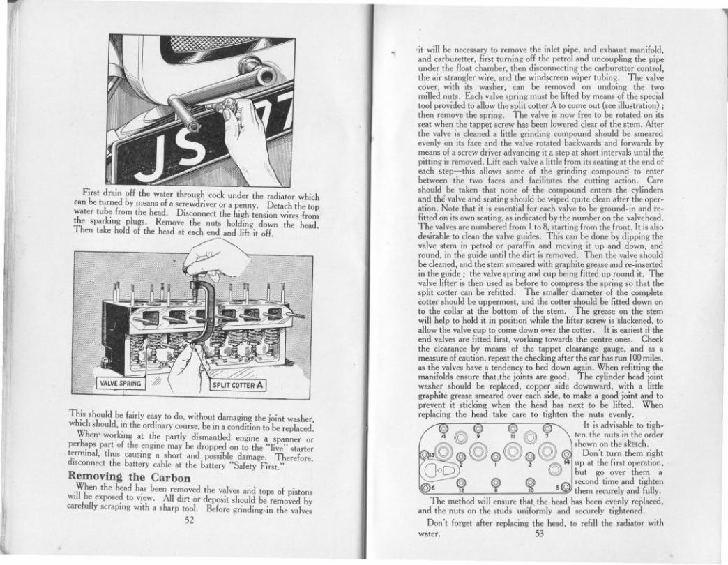
r'~I,
il
,1'1
I
.it will be necessary to remove the inlet pipe, and exhaust manifold,and carburetter, first turning off the petrol and uncoupling the pipeunder the float chamber, then disconnecting the carburetter control,the air strangler wire, and the windscreen wiper tubing. The valvecover, with its washer, can be removed on undoing the twomilled nuts. Each valve spring must be lifted by means of the specialtool provided to allow the split cotter A to come out (see illustration) ;then remove the spring. The valve is now free to be rotated on itsseat when the tappet screw has been lowered clear of the stem. Afterthe valve is cleaned a little grinding compound should be smearedevenly on its face and the valve rotated backwards and forwards bymeans of a screw driver advancing it a step at short intervals until thepitting is removed. Lift each valve a little from its seating at the end ofeach step-this allows some of the grinding compound to enterbetween the two faces and facilitates the cutting action. Careshould be taken that none of the compound enters the cylindersand the valve and seating should be wiped quite clean after the oper-ation. Note that it is essential for each valve to be ground-in and re-fitted on its own seating, as indicated by the number on the valvehead.The valves are numbered from I to 8, starting from the front. It is alsodesirable to clean the valve guides. This can be done by dipping thevalve stem in petrol or paraffin and moving it up and down, andround, in the guide until the dirt is removed. Then the valve shouldbe cleaned, and the stem smeared with graphite grease and re-insertedin the guide; the valve spring and cup being fitted up round it. Thevalve lifter is then used as before to compress the spring so that thesplit cotter can be refitted. The smaller diameter of the completecotter should be uppermost, and the cotter should be fitted down onto the collar at the bottom of the stem. The grease on the stemwill help to hold it in position while the lifter screw is slackened, toallow the valve cup to come down over the cotter. It is easiest if theend valves are fitted first, working towards the centre ones. Checkthe clearance by means of the tappet clearange gauge, and as ameasure of caution, repeat the checking after the car has run 100miles.as the valves have a tendency to bed down again. When refitting themanifolds ensure thaUhe joints are good. The cylinder head jointwasher should be replaced, copper side downward, with a littlegraphite grease smeared over each side, to make a good joint and toprevent it sticking when the head has next to be lifted. Whenreplacing the head take care to tighten the nuts evenly.
0 0 0 0 It is advisable to tigh-
4 @ 9 ,,@ 1 ten the nuts in the order
~ @ @ @shown on thes~<!tch.
~ 16\ ~ (§) 0 @ 0 0 Don't tu~n them r\ght
0 :;r I J fA>,'4 up at the fIrSt operallon.oD ~ but go over them a
"" @ @ @ ~ second time and tighten106 12 . 10 s~ them securely and fully.
The method will ensure that the head has been evenly replaced,and the nuts on the studs uniformly and securely tightened.
Don't forget after replacing the head, to refill the radiator withwater. 53
.I
First drain off the water through cock under the radiator whichcan be turned by meansof a screwdriveror a penny. Detach the topwater tube from the head. Disconnectthe high tension wires fromthe sparking plugs. Remove the nuts holding down the head.Then take hold of the head at each end and lift it off.
11'
m
~il
I~
1,1
L
This should be fairly easy to do, without damaging the joint washer,which should, in the ordinary course, be in a condition to be replaced.
When" working at the partly dismantled engine a spanner orperhaps part of the engine may be dropped on to the "live" starterterminal, thus causing a short and possible damage. Therefore,disconnect the battery cable at the battery "Safety First."Removing the Carbon
When the head has been removedthe valvesand tops of pistonswill be exposedto view. All dirt or deposit should be removed bycarefullyscraping with a sharp tool. Before grinding-in the valves
52

-'Irl
1/1
III
1'1
OIL MONTHLY
To adjust the foot brake: Under the car and approximately underthe foot controls is a wing nut.
This must be screwed towards the front of the engineuntil the brakes go full on when the pedal is depressed about2in. When the pedal is up, the brake shoes should not rub thewheel drums in which they operate.
For adjusting the rear brakes, which may be necessary afterre-lining the shoes, an individual adjustment for each of the rearbrake cables is provided. A screwed end, to which the cable isattached, screws into the front fork-end, which secures the cable tothe compensating tube lever. By removing the fork-end from thelever (a pin, secured by a split-pin, holds it) the fork can be screwedfurther on or oH the screwed cable end to effect the adjustment.
The cable must not be twisted while this isbeing done. To test whether both brakes
engage equally atthe same time,jack-up the backaxle, and with thebrake pedal presseddown, turn eachwheel by hand tojudge the brakingeffect.
Having done thisthe hand brakelever should be ad-justed. This isdone from underthe car, by hand.A wing nut isprovided by meansof which the slackbetween the handbrake lever and thebrake gear is takenup.
The hand brakelever must bepushed forwardto its limit, that isthe brake must be
right off. Then turn the wing nut clockwise until the hand brakelever will only move freely one notch in the rack withoutmoving the brake mechanism.
If this short movement is made without beginning to operate thebrakes, it indicates that the brake shoes will not rub against thedrums when the hand brake lever is in the" oH" position; and thatthe adjustment has been properly made.
Lifting the Cylinder BlockFor access to the pistons (except the piston crowns), and the
connecting rods, or for fitting a new tappet plunger or guide, orvalve guide, it is necessary to lift the cylinder hlock. The threenuts on the distributor side are easily removed, also the three barrelnuts on the valve side can be removed without difficulty whenthe valve cover has been taken off. For access to the nut at thefront of the cylinder block the dynamo and casing with the fanbracket and fan, must be lifted clear. First pull the ignition leadsand the lead from the coil, from their sockets in the distributor cover.Disconnect the dynamo and the ignition control, and remove thefan belt. The casing is secured by three set screws and a nut. Withthe casing removed, the front cylinder block nut is accessible. Foraccess to the rear nut of the block, it is advisable to lift the starter-motor and casing, from its mounting over the flywheel. This isdone by removing the two set screws, and lifting the casing clearvertically off its positioning dowel. The cylinder block can belifted when the lower hose connection has been removed. Whenrefitting the starter-motor casing, the larger set screw is required atthe nearside of the casing. There is no joint washer between thiscasing and the crankcase, but paper joint washers are used betweenthe cylinder block and the crankcase, also under the dynamo casing.These joints must be oil-tight. When refitting the cylinder block itis necessary to use sleeves on the pistons to compress the rings.These piston ring sleeves are among the extra tools obtainable fromthe Service Department of the Austin Motor Co., Ltd. It will benecessary to retime the ignition after re-assembling.
Adjusting the BrakesBoth the hand brake and the foot brake operate on all four wheels.
They require adjusting when the hand lever can be pulled right backto the full travel on the rack, and when the pedal can be pushednearly to the floor-board without either brake holding the wheels.The car should never be taken out when in this condition, butshould be attended to at once.
Ili
II!
'I11
'd1'
1,I"
1/111
:1
"11:,I"
I
'I~
Ill.!
11'I\i
I,ll
~
Ii!~:'I
II~:
I
if
I1
Ii
l55
54

I'Re-lining the Brakes
To re-line the brakes it is necessaryfirst to remove the wheel,and then the brake drum, by unscrewing the three screwdriver
11
lIi
Ii
I11.1
!II'
H
II''iil
screws which secure it to the hub; and, before the shoes can beremoved for re-lining, the hub and wheel bearing must be extracted.For this a special hub extractor is supplied in the tool kit.
!iIIl"
,il,..,
i'
Rear Brakes
For the rear wheel brakes (see illustration on page 41) removethe axle shaft nut, having first taken out the split pin, and extractthe outer portion of the hub by screwing the extractor on thescrewed end, and turning the extractor bolt which bears on theend of the axle shaft. Remove the key from its keyway in theaxle shaft. Next remove the bearing nut, having knocked backthe tang of the washer loclang it, and prise the inner portion of thehub or felt housing together with felt packing and bearing, offthe end of the axle casing. Do not damage the paper washerbetween the hub and the felt housing faces, as it is important tomake a good joint on reassembling, to prevent the hub lubricantpenetrating to the brake. If this inner portion of the hub does notcome off the axle casing easily, the outer half should be refittedas closely as possible, using the wheel nuts to draw the two halvestogether. Then use the hub extractor a second time, and so removethe hub together with bearing and packing. The brake shoes cannow be pulled off the cam and pivot pin, and the springs unhooked.
h)
flii
56
.The old linings can then be detached by punching or drilling outthe rivets.
The brake linings should be clamped to the shoes while theriveting is in progress, as it is essential that they should bed downon the shoes over their whole area. When the linings have beenrivetted in position, bevel off at each end for about t inch with acoarse file.
Reassembling
To reassemble, replace the shoes with their springs on the camand pivot pin. Replace the inner portion of the hub or felt housingwith the bearing and packing on the axle casing end, and push uphome by tightening the bearing nut, which must be locked by thelocking washer in the same way as before dismantling. Replace thepaper joint washer on the felt housing face, insert the key in theshaft, push the hub over the axle shaft, on the key, and draw it upto the felt housing by the wheel nuts on their studs. When thejoint faces of the hub and the felt housing are together replacethe axle nut and tighten securely up to the hub boss. Rememberto insert the split pin through the nut. Then remove the wheel nutsfrom the hub, fit the brake drum, and insert and tighten the threescrewdriver screws.
Front Brakes
For the front brakes (see illustration on page 40) the operationis somewhat similar. Having removed the wheel, and the brakedrum, secured by the three screws, remove the hub cap, and screwon the extractor in its place. Before proceeding further, removethe plug (A) from the hub, or unscrew it for about three turns;otherwise it will foul the outer hub bearing when the hub is beingextracted. Draw off .the outer portion of the hub. The axlenut and split pin will now be accessible for removal. Replacethe outer portion of the hub and pull it to its original positionby the wheel nuts, as in the case of the rear wheel. By means ofthe extractor draw off the hub with its bearing and packing. Thebrake shoes are left clear for removal. On reassembling rememberto fit a new split pin through the axle and nut; there is a hole in
t~e end of the hub through which the pin :an be inserted,
It is always necessary to re-line all four brake shoes on the oneaxle at the same time, and after the re-lining it may be necessaryto slack off the brake adjustment before the brake drum can bereplaced.
After re-lining the brakes make sure that the hubs contain sufficientlubricant, and re-adjust the brakes if necessary.
,I57

Tracking AdjustmentOne of the causes of premature tyre wear is the front wheels
being out of track. The wheels, if they are correctly trackingshould not be parallel, but should be tin. doser between the rimsin front of the axle than they are behind. This difference, or"toe-in" as it is called, allows for working clearances of the steeringconnections, and any slight spring of the parts, so that when thecar is running the wheels are as near parallel as possible. If onchecking this difference, it is greater or smaller than t in. the trackingshould be adjusted. This is not difficult to effect. It is necessaryto remove the cross tube lever, on the near side, from the swivelaxle. It is secured by a nut on the front of the swivel axle, underwhich there is a spring washer. With this done, the steering crosstube is freed at the near side for the adjustment. On the clampingbolt of the steering arm jaw being slackened, the jaw can be screwedfurther on, or off, the cross tube, for so many complete turns asmay be necessary. This movement will enable the correct adjust-ment to be attained; then the clamping bolt is re-tightened. Onrefitting the cross tube lever to the axle, tighten the nut securely,with the spring washer under it. This, as well as the steeringadjustment described below, is one of the adjustments which it isadvisable to leave to the Austin agent to effect, who is properlyequipped for the work.
Adjustment of SteeringIf after continual use slackness should be felt in the steering,
two adjustments are available ;- To take up the play in the column,loosen the nut which tightens the bracket supporting the steeringouter column to the instrument board, unscrew locking peg (A) and
-I!
I
I:
If
il
111
11
~I1',1,I)'
lj",;,.,
1,1"OUTER
COLUMNI
SLEEVEC'1,
'I,LOCKING PEG A
(OTHER SiDE)w'
COVERE
NUTD
~'
t
,
.,clamping bolt (B) then turn the sleeve (C) with the special spannerprovided for the purpose, until the play has been removed. Donot screw the sleeve in too tight or the steering will then becomestiff. Having adjusted the sleeve correctly, screw in the lockingpeg so that it enters one of the slots of the sleeve, tighten up theclamping bolt, and the supporting hracket to the instrument board.
To take up the clearance between the worm and worm wheel,due to wear, remove the locbng plates and slacken the three nuts(D) holding the cover (E) to the worm casing, then turn adjustingscrew (F) so as to slightly draw the cover in the direction of the worm.Care must be taken that the worm wheel is not brought too tightlyinto mesh with the worm or it will make the steering exceedinglyhard and stiff. Having made the adjustment be sure and tightenup the three nuts (D) and lock them with the locking plates.
Should it be desirable to remove the steering worm wheel fromthe casing, it is only necessary to slacken the adjusting nut (F) andremove the three nuts (D) when the cover (E) can be withdrawntogether with the worm wheel and steering arm. The steeringcolumn with control rods can be withdrawn by first removing controllevers and nut, then slackening locking peg (A) and clamping bolt (B),and unscrewing the sleeve (C). These adjustments, again, should beleft to an Austin agent to effect.
CLAMPINGSBOLT
Adjusting Austin Front Shock AbsorbersThe shock absorber is set to a certain initial tension before it
leaves the factory, and no change in this adjustment should benecessary for a very considerable time.
Re-adjustment may only become necessary after several thousandmiles of car travel, and should be made only when the spring move-ment seems too free. It should be noted that, normally, the fullbenefit of the shock absorbers will not be felt when the car istravelling at low speeds, as under these conditions the spring move-ment is very limited, but, as the speed increases their effect becomesmore pronounced, especially over bad roads when the spring actionis most severe. Testing should, therefore, be carried out at com-paratively high average touring speeds and adjustment made tosuit these conditions.
The frictional resistance required to effectively control the actionof the springs is comparatively small, and care should be taken notto alter the pressure, when adjusting, more than is absolutelynecessary in order to obtain the desired results.
For fast sporting cars and for road and track racing, a consid~rableincrease in pressure may, of course, be required.
When adjustment does become necessary, carefully note theriding qualities of the car, and if the spring action seems too retardedor stiff, reduce the frictional resistance of the shock absorbers byturning the centre adjusting nut to the left, or counter-clockwise,after slackening the lock nut. If the spring action seems too free,increase the frictional resistance by turning the adjusting nut to theright, or clockwise. After adjusting, tighten the lock-nut.
ADJUSTINGSCREWF
STEERING ARM G
5859
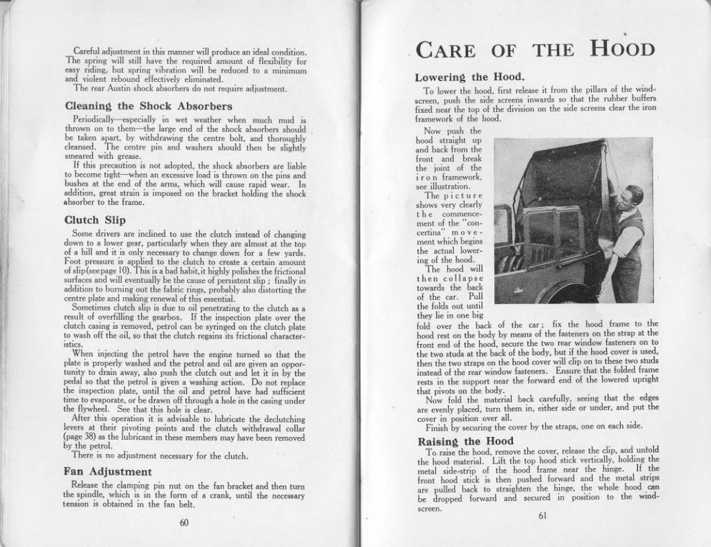
Lowering the Hood.To lower the hood, first release it from the pillars of the wind-
screen, push the side screens inwards so that the rubber bullersfixed near the top of the division on the side screens clear the ironframework of the hood.
Now push thehood straight upand back from thefront and breakthe joint of thei r 0 n framework.see illustration.
The pictureshows very clearlythe commence-ment of the "con-certina" m 0 v e-ment which beginsthe actual lower-ing of the hood.
The hood willthen collapsetowards the backof the car. Pullthe folds out untilthey lie in one bigfold over the back of the car; fix the hood frame to thehood rest on the body by means of the fasteners on the strap at thefront end of the hood, secure the two rear window fasteners on tothe two studs at the back of the body, but if the hood cover is used,then the two straps on the hood cover will clip on to these two studsinstead of the rear window fasteners. Ensure that the folded framerests in the support near the forward end of the lowered uprightthat pivots on the body.
Now fold the material back carefully, seeing that the edgesare evenly placed, turn them in, either side or under, and put thecover in position over all.
Finish by securing the cover by the straps, one on each side.
Raising the HoodTo raise the hood, remove the cover, release the clip, and unlold
the hood material. Lift the top hood stick vertically, holding themetal side-strip of the hood frame near the hinge. If thefront hood stick is then pushed forward and the metal stripsare pulled back to straighten the hinge, the whole hood ambe dropped forward and secured in position to the wind-screen.
~
11
I
li I
1I f
11 [
I11I
Careful adjustment in this manner will produce an ideal condition.The spring will still have the required amount of flexibility foreasy riding, but spring vibration will be reduced to a minimumand violent rebound effectively eliminated.
The rear Austin shock absorbers do not require adjustment.
CARE
Cleaning the Shock AbsorbersPeriodically-especially in wet weather when much mud is
thrown on to them--the large end of the shock absorbers shouldbe taken apart, by withdrawing the centre bolt, and thoroughlycleansed. The centre pin and washers should then be slightlysmeared with grease.
If this precaution is not adopted, the shock absorbers are liableto become tight-when an excessive load is thrown on the pins andbushes at the end of the arms, which will cause rapid wear. Inaddition, great strain is imposed on the bracket holding the shockabsorber to the frame.
I,!
"""'
I
if1",1'rl''[
!~ j'i'
1
['
,])
J
Clutch SlipSome drivers are inclined to use the clutch instead of changing
down to a lower gear, particularly when they are almost at the topof a hill and it is only necessary to change down for a few yards.Foot pressure is applied to the clutch to create a certain amountof slip (see page 10). This is a bad habit, it highly polishes the frictionalsurfaces and will eventually be the cause of persistent slip; finally inaddition to burning out the fabric rings, probably also distorting thecentre plate and making renewal of this essential.
Sometimes clutch slip is due to oil penetrating to the clutch as aresult of overfilling the gearbox. If the inspection plate over theclutch casing is removed, petrol can be syringed on the clutch plateto wash off the oil, so that the clutch regains its frictional character-istics.
When injecting the petrol have the engine turned so that theplate is properly washed and the petrol and oil are given an oppor-tunity to drain away, also push the clutch out and let it in by thepedal so that the petrol is given a washing action. Do not replacethe inspection plate, until the oil and petrol have had sufficienttime to evaporate, or be drawn off through a hole in the casing underthe flywheel. See that this hole is clear.
After this operation it is advisable to lubricate the declutchinglevers at their pivoting points and the clutch withdrawal collar(page 38) as the lubricant in these members may have been removedby the petrol.
There is no adjustment necessary for the clutch.
Fan AdjustmentRelease the clamping pin nut on the fan bracket and then turn
the spindle. which is in the form of a crank, until the necessarytension is ohtained in the fan belt.
Ii
or
I1
I,l
'~,
"
'I,
~:
li,
60
~
.OF THE HOOD
61

Care of the HoodCare should he taken in folding down the hood to see that the
original folds are used. Should the car have been used in wetweather leave the hood up to dry. Never fold it when wet.The Side Curtains
The side curtains are secured against movement or rattle byset screws. The pegs at the bottom of the curtains fit into holes inthe aluminium rail on the top of the bodywork, and these pegs arefirmly held by screws. Before the sidescreens can be removed,these screws must be slackened with a coin or screwdriver, and alsothe nut on the inner side of the main hood stick fulcrum.
Provision has now been made to carry the side screens in a recess~t the back of the rear squab, where they are safe from injury whennot in use.
First loosen the screws which secure the pegs firmly to the bodyand doors, then lift out the side screens.
Unfasten the strap at the top of the squab, pull the back seatcushions forward, and lift out the squab.
The rear curtains are dealt with first. Their pegs go into theslots. Then the front curtains are put away; their pegs fit into theround holes.
The hinges on all the screens should be toward the side of the car.The nearside curtains are stowed on the nearside of the compart.
ment. Replace the squab, fasten the press stud on the strap, andpush the seat cushion into its proper position.
Float-on-Air Seat InteriorsThe essence of comfort with "Moseley
Float.on.Air" upholstery is low pressure-to blow up the cushions at all hard is todestroy their powers of absorbing vibration.The seat should be quite soft to the touch,the hand pressed on the surface sinking wellin. If the seats do not give perfect resultsrelease air from the valve, as the usual faultis over inflation. The butt ended portionrunning round the sides and front of eachinterior is separately inflated and should bemoderately well blown up. The centreportion of each interior is also separatelyinflated, and the pressure should be suchthat the base of the seat can be felt whenpressed with the closed fist. This gives theideal pressure and support when sat upon.
To adjust the air pressure open the flapat the rear of the cushion, exposing thevalves. The valve at the side inflates the"hutt ended portion" above referred to;the other valve (or valves in the rear cushion)inflates the centre section. Draw gently on
62
-'I'
;iil
11
I
I
I.
,!
II
i'l
~
.
the tabs till the rubber valve protrudes about one inch, do not pull.hard otherwise the valve may be damaged. Roll back the rubber ringtowards the cushion when the plug can be readily removed from thetube. Blow with the mouth or release air as required.Moisten the plug and reinsert as far as it will go, roll ring back untilit engages in the depression caused by slot in plug. Push back thevalve till the cap is flush with the surface and refasten the flap.
Storing the CarShould the car be laid up in the garage for long periods, the fuel
and water should be drained off and the batteries removed, andweight taken off the tyres.
CARE of the BODYWORK
FOR the car to look well and keep its beauty and smart appear-ance, the body must be given its share of attention; it mustnot be neglected. -
,1:,~...,..,"",,7'
~",
;;,--=.1, -'..."
~'~i
WashingThe cellulose finish of the car is easily cleaned and polished.
In summer weather when the car is only dusty the dust can be lightlyflicked off without water and there is no risk of damaging the finish.When the car is muddy, wash off well with clean running water-wash the mud off-don't rub it off. Remove any grease or tarsplashes with petrol. Don't use the same sponge and cleaningcloths for the chassis and springs and other greasy parts as are usedfor the coachwork.
PolishingDry off and then polish with one of the special polishes now
marketed. Such preparations impart a brilliant surface and pre.serve and beautify the body. On no account should metal polishesbe used, as are sometimes advertised for cellulose. It has beenfound that the more the surface of the cellulose finish is rubbed bythe polishing cloth, the smoother and more lasting is the lustreimparted.
Door locks, hinges and other small working parts should be givena drop or two of oil occasionally.
DON'T ,.
~.............. ..
"""'..m"
Don't, please don't-Don't leave the car in gear with the handbrake off.Don't make a fast run with the radiator muff down.Don't fill the radiator with cold water when the engine is hot.Don't try to turn the engine without first pushing the starting.handle
in to engage fully with the starting nut.Don't be cruel to the starter if the engine will not fire.Don't put an excessive quantity of lubricant in the gear box.
63

-
I
I
I
Don't forget the ignition switch when starting up.Don't leave the ignition switched on when the engine is not running.Don't coast with the engine running and the clutch held out.Don't run the engine in a closed garage. (The exhaust gases are
highly toxic and a very small amount in a restricted atmospherewill produce grave, if not fatal, results).
I
All Austin Dealers carry stocks of genuine Austin replacements,and applications for spare parts should be made to them. Client.will then be certain that the replacements are made by parts manu-factured by The Austin Motor Company and carrying their highreputation for quality and workmanship.
11
STANDARD REPAIR
CHARGES
I
lI
~
THE following adjustments and repairs described in thishandbook are included in the Austin Seven Schedule ofCharges for Repairs, which quotes over one hundred prices forrepairs to the Austin Seven.
Greasing spring shackles, steering and brake, and other smallconnections.
Ditto, but including rear axle, universal joint, steering box andfront hubs.
Taking down, cleaning and greasing all road springs, reassemblingwith new holts and bushes where required.Dismantling shock absorbers, then cleaning and adjusting andrefixing.Adjusting and compensating brakes.Relining brakes, front or rear.
Removing cylinder head; decarbonising and grinding in valves,adjusting tappets and tuning-up engine on the road.
Fitting new cylinder head and/or gasket.Adjusting valve tappets, cleaning and adjusting contact breaker,.distributor and sparking plugs; cleaning out carburetter jets.Fitting new valves.
Removing base chamber, cleaning oil filter, examining interiorof engine, and refilling with new oil.
Removing dynamo from car; cleaning and adjusting, examiningbattery and connections, and refilling battery with acid as required.Tracking up front wheels by adjusting length of cross steeringtube.
Adjusting mesh of steering worm and wheel.Owners will find it to their advantage to have their car adjustments.and repairs effected by Austin agents at these standard prices.
64
I1
rI
I
. !
.TOOLS and ACCESSORIES
SUPPLIED WITH THE CAR.The tools are supplied in a sealed cardboard box. The owner
should see the seals are intact when the car is delivered.The tools should be carefully checked against the list shown at the
end of the handbook, then put into their places in the wraps, andstowed away in the car.
t in. and -i\r in. box spanner. Spanner for monoblocnuts.-i\rin. X i in. box spanner. Tool wrap.t in. and! in. box spanner. Sparking-plug box spanner and-i\r in. and t in. double open- tommy bar.
end spanner, Brace for detachable wheels.f. in. and i in. double open- Tyre lever.
e'.'d spanne.r. Tyre pump.1'0-m. and! m. double open- Lifting jack, with handle.
end spanner. .Adjustable spanner, 4 in. Screw~nver.Hub-cap and steering column Sparking plug and tappet
sleeve spanner. clearance g~uge.Ignition spanner. Grease gun wIth adaptor.Tappet adjusting spanner. . Valve-spring lilter.2 Radiator hose clips. Combination pliers.1 Extra ignition key. Hub extractor and screw.
A spare cylinder-head joint washer is also supplied.Extra with sports model: Rear axle oiling adapter, valve
grinding tool, special valve lilter, induction pipe flange spanner.Extra with unsupercharged sports model: valve grinding too\'
special valve lilter.
THE AUSTIN MAGAZINEA high-class monlhly molar journal of wide.appeal and special inleresllo lhe Austin ownerSUBSCRIPTION. 7/6 per annum (post free).4d. MONTHLY From any Bookstall or Newsagent.
Send your SubscriPtion NO W-
"THE AUSTIN MAGAZINE,"SUBSCRIPTION DEPARTMENT,
LONGBRIDGE, BirminghlUJ1.
65

THE Au.tin Motor Co., Ltd., accept uo liability undertbe terms of their Warranty for Tyres, Speed.ometers, or the Electrical Equipment, or other
good., including Coachwork, not of their own Manufacture.
All claims relating to any of tbese part. or fittinglor orden for repair. to tbem, .hould be addrelled totheir manufacturen.
-
d
II
I
I
I
AUSTIN
II
li
)'
SEVEN Tyres and Tubes" Dunlop " Dunlop Rubber Co., Ltd., Fort Dunlop
Erdington, Birmingham.
EQUIPMENT
Carburetter"Zenith" Zenith Carburetter Co., Ltd., 40.42, Newman
Street, London, W.!.
Horns" A.R." A. Rist, Ltd., Waveney Works, Lowestoh.
For ownen' information we give below tbe name.and addrelles of the manufacturen, or .upplien of theequipment fitted on the Au.tin Seven.
Lifting Jacks"SheIley" R. T. SheIley,Ltd., Aston Brook Street,
Birmingham.
I
Y!
l
Petrol PumpIMPORTANT ,," A.C:' Sphinx Sparking Plug Co" Bradfo«!
Street, Birmingham. '"When claims under parantee are being made, it i.
absolutely nece.sary to quote the type and number ofthe car, and tbe commissioning date.
I
Electrical and Ignition Equipment, Lampsand Batteries
Owner's Name"Luca. "
and" c.A.V."
11
Windscreen"Luca. "
Grease Gun.. Enots ..
I1
'I
'I
Speedometer"Smith ..
Joseph Luca., Ltd., Great Hampton Street,Birmingham and Dordrecht Road, ActooVale, Loodon, WJ,
Address
WiperJoseph Lucas, Ltd" Great Hampton Street.
Birmingham and Dordrecht Road, Actor>Vale, London, WJ,
Car No.
Benton and Stone, Ltd" Bracebridge Street.Binmingham. Registration No.
S, Smith and Son. (MA), Ltd., CricklewoodWork., London, N,W.2.
Drioing Licence No.
Insurance Policy No,
66
67

..
i'IIIlil"
IIiI
"LUCAS" SERVICE DEPOTS
'1
1
r
BELFAST, 3-5, Calvin Street, Mountpottinger.Telegrams: "Servdep," Belfast. Telephone : Belfast 7017.
BIRMINGHAM, 18, Great Hampton Street.Telegrams: "Lucas, Birmingham." Telephone: Central8401
(10 lines)BRIGHTON, 85, Old Shoreham Road, Hove.
Telegrams: "Luserv Brighton." Telephone: Preston 300](4 lines)
11
ilili::1
~ :':1
1'"
!II,
~.
BRISTOL, 345, Bath Road.Telegrams: "Kingly, Bristol." Telephone: Bristol '76001
(4 lines)CARDIFF, 54a, Penarth Road.
Telegrams: "Lucas, Cardiff." Telephone : Cardiff 4603(4 line.)
'I"I,.J
.,
COVENTRY, Priory Street. '
Telegrams: "Lucas, Coventry." Telephone: Coventry 3068
DUBLIN, Portland Street North, North Circular Road.Telegrams: "Luserv, Duhlin." Telephone: Drumcondra 434
(6 lines)EDINBURGH, 11,32, Stevenson Road, Gorgie.
Telegrams: "Luserv, Edinhurgh." Telephone: Edinhurgh 62921(4 lines)
GLASGOW, 227-229, St. George's Road.Telegrams: "Luserv, Glasgow." Telephone: Douglas3075
(5 lines)
r',,'
LEEDS, 64, Roseville Road.Telegrams: "Luserdep, Leeds." Telephone : Leeds 28591
(5 lines)
,11,
~,
I11
.,
III:
1
'I
11
I,
LIVERPOOL, 13,450-456,Edge Lane.Telegrams: "Luserv, Liverpool." Telephone: Old Swan 1408
(4 lines)
'11
11,LONDON, Dordrecht Road, Acton Vale, WJ,Telegrams: "Dynomagna, Ealux, London."Telephone: Shepherds Bush 3160(10 lines).
LONDON,757-759, High Road, Leyton, E.IO.Telegrams: "Luserdep, Wait, London."Telephone: Leytonstone 3361 (4 lines).
LONDON. 155, Merton Road, Wandsworth, S.W.18.Telegrams: "Luserv, Put, London."Telephone : Putney 5131 (6 lines) and 5501.
MANCHESTER, Talbot Road, Stretford.Telegrams: "Lucas, Stretford." Telephone : Longford 110I,
(5 lines)
'II
Ii
NEWCASTLE-ON-TYNE, 2,64-66, St. Mary's Place.Telegrams: "Motolite. Newcastle-on-Tyne."Telephone: Central: 25571 (3 lines).
In addition, there 'are Lucas-C.A.V.-Rotax Official Battery ServiceAgents in important centres throughout the country.
68