of the 10 rater rule - international ten rater...
TRANSCRIPT

100 YEARS OF THE
10 RATER RULE
RUSSELL POTTS
COPYRIGHT 1987
1

This 5th World Championship regatta for radio 10-raters marks the centenary of the Length and Sail Area Rule, introduced by the (English) Yacht Racing Association (YRA) on 1 January 1887. Though it had only a brief life as a full size Rule, it was quickly adopted by model yachtsmen and has continued in use by them ever since. It was also the vehicle for many significant advances in model yacht design and sailing practice and its 100 year history may be used to illustrate the way design is influenced by current theory and by available technology.
THE ‘1730’ RULE Before 1887, the Rule for full size craft was the Tonnage Rule of 1881 to the ‘1730’ formula:
Tonnage for rating = (L+B)2 X B 1730
(L = Load Waterline Length; B = Extreme Beam)
At this period full size yachts of widely varying dimensions raced together and the Rule sought to measure the ‘size’ of the hull so that the advantage of sheer size could be eliminated by various systems of ‘Time on Distance’ handicapping. The ‘1730’ Rule taxed beam very heavily and typically produced deep narrow hulls with little form stability. Stability was supplied by a very heavy lead keel carried deep. The type was known as ‘plank on edge’ or ‘lead mine’ for obvious reasons. Sail area was unmeasured and yachts were heavily sparred and extravagantly canvassed, requiring large crews to sail them effectively under racing conditions. When their racing days were over, they were regarded as acceptable cruisers under reduced rig; the hull form gave standing headroom in relatively small boats and the narrowness of the accommodation and the difficulties in taking the ground in tidal harbours were largely discounted.
‘ Clara’ 20 tons midship section
2

MODELS UNDER THE ‘1730 RULE Though the ‘1730’ Rule was in force only from 1881 to 1887, it was of great importance in the development of model yachting in Britain. During this period the sport was first beginning to be organised on more than a local level. One of the main aims of Tom Bruce, the editor of the first specialist model magazine ‘Model Yachtsman’, was to promote interclub racing. This demanded the use of a common Rule and led many model yacht clubs to builds boats that would rate as 10 Tonners under the ‘1730’ Rule when measured at a scale of 1 inch to the foot (1:12).
In model sizes, the 10 Tonner was a boat ‘of convenient size to take on a train to a distant town and light enough to be carried from the railway station to the lake without undue effort’. (About 48 inches loa and total displacement of up to 20 pounds.) Model 10 Tonners resembled their full size sisters in general form but were in many cases more extreme in their proportions with a length of five or six beams and even more outrageous sail plans. They used a series of rigs of various sizes to suit weather conditions. The boats had a long straight of keel and were sailed to windward without rudder, using sail trim alone. Off the wind, if they raced off wind at all, they were steered by the use of a free-swinging weighted rudder. A range of different sizes and weights was used to suit the course and wind strength. Many clubs felt that the problem of off wind control was too difficult; others maintained that an intelligent use of a suite of weighted rudders would give all the control that could be desired. Much depended on local traditions and conditions.
At this period, the model yachtsman could make no mid course adjustments to helm or sail trim to meet changes in wind strength and direction. Thus, straight running and the absence of steering tendencies were of paramount importance. There was, however, no theory to support his design efforts to achieve this end. Hull ‘balance’ was recognised as desirable, and most naval architects emphasised the importance of ‘harmony between the entry and delivery of the hull; none gave any indication of how this could be assured at the design stage, other than by intuition and long experience. Well into the 20th century, many successful full size yachts were notoriously hard mouthed and difficult to control in a blow, with the long narrow straight keeled boats to the ‘1730’ Rule, this did not create too much difficulty.
3

Fig 3 a model 10T
THE LENGTH AND SAIL AREA RULE In 1887, in an attempt to produce a less stereotyped form of hull, the YRA introduced the Length and Sail Area Rule. This was devised by Dixon Kemp, who was both Secretary of the YRA and Yachting Editor of the sporting weekly ‘The Field’. This rule for the first time took account of the propulsive power of the sail area as well as of the size of the hull. The formula was:
Rating = L X SA 6000 (L = Load Waterline Length; SA = Sail Area, measuring the whole area of all sails of the largest rig.) The rule for the first time required a limited sail area to be used to the maximum efficiency, and the hull resistance to be reduced by more efficient design. The effect was for the hull to become lighter, shallower and broader, with much of the stability coming from the hull form. Simultaneously, the hull profile began to be cut away, as the findings of William Froude on the importance of skin friction came to be generally accepted. As the hull depth and displacement were reduced, fins became narrower and deeper, with smaller amounts of lead carried at relatively greater depths.
4

These trends were carried furthest and fastest in the ‘Small Rater’ classes of level rated dayboat that sailed in the Solent. The 0.5 and 1 rater classes in particular were the arena for fierce competition in design and construction. These small keelboat and centreboard classes, in which Soper, Sibbick, Payne and Linton Hope were the leading designers, saw the development of the ‘skimming dish’ hull with great beam, long overhangs, a fin and bulb keel, and a skeg mounted or spade rudder. Great emphasis was placed on minimum structure weights. The type also produced the ‘Solent rig’, which maximised the efficiency of the limited sail area by concentrating it in a high peaked gaff mainsail, often with through battens, and a small jib.
Fig 4 ‘Unora’, 1894; Solent Small Rater
THE COLLAPSE OF THE LSA RULE Despite the success of the Rule in fostering an exciting, if expensive, group of small dayboat racers, it was not popular with those who wanted a rather large boat. The Victorian yachtsman expected a high standard of accommodation in boats large enough to live aboard and the lsa Rule with its shallow hull form did not permit standing headroom until the yachts reached quite large sizes. This meant that a racing yacht which had become outclassed could not be used for the style of cruising that owners of the time preferred and thus had little or no resale value. As early as 1892 the falling off of new orders for yachts of over 10 rating was causing concern to yacht designers and builders, who feared for their livelihoods. A committee, led by Fife and Watson, waited upon the YRA to urge that a new Rule be introduced which would require hull forms that would give adequate accommodation and preserve the link between racing and cruising yachts. It was also argued that the more extreme styles of boat under the Rule were unseaworthy. This is an objection that tends to be raised against any Rule by those who, for whatever reason, wish it to be changed. The YRA declined to take action, on the grounds that ‘their members desired speed above all’. It was also known that 1893 would see the launch of a large (142-rater) yacht to the Rule for Edward, Prince of Wales, and the YRA did not wish to snub this move to give a Royal cachet to yacht racing. Watson’s design for the Prince, the famous ‘Britannia’, had some success in her first few seasons and prompted a few other wealthy owners to build large yachts to the Rule, but this did not make the Rule acceptable to owners of smaller yachts. In 1896 the YRA agreed to adopt a Linear Rating Rule devised by J. E. Froude. This was intended to bring racing and cruising yachts together in a common form and used a system designed to ensure that even out-and-out racing craft would have a hull form that would provide a practical cruiser with ample accommodation. This Rule came into use in January 1897 and set the broad pattern that was followed in the various revisions of the Linear Rating Rule and in the International Rule introduced by a conference of European Yachting Associations in 1907 and revised several times subsequently.
5

Though the Linear and International Rules were adopted by model yachtsmen, they never supplanted the popularity of the 10-rater, which continued to be by far the most popular class in Britain until well after 1945. From the turn of the century until the late 1960’s there was an active and highly competitive 10-rater League in the London area. Many important design innovations were developed within the context of 10-rater competition.
EARLY MODELS UNDER THE LSA RULE Model yachtsmen did not immediately adopt the new lsa Rule in 1886. They were in general keen to build to the current full size Rule, but the 10 Tonner already existed as a common interclub boat and was not easily displaced. There was also uncertainty over which was the best size to adopt for a model under the lsa Rule and initially the 15-rater was favoured. The ‘Model Yachtsman’ ran a design competition for 15 raters in 1891 and these are the earliest surviving model designs to the Rule. The designs mimic the style of larger full size yachts under the Rule, with a full keel and wine glass hull form; the rig is usually a cutter. Similar competitions for 10-rater designs were held in 1893 and 1894. By this time some of the entries are looking to the style of the Solent ‘small rater’, with a shallower canoe body with fin keel. The competition entries range from 38 to 40 inches lwl and from 19 to 25 pounds displacement. Sail area was in the region of 1500 square inches.
Fig 6 ‘Blackbird’ 10-r, Greenock 1895
6

DESIGNING COMPETITION
FOR 10-RATERS.
Fig 5, 1894 Competition entries;
The main design problem faced at this stage was to produce a hull which combined the speed advantages of reduced wetted area with the tractable steering characteristics essential in a successful model. The specialist magazines of the period make it clear that the most advanced modellers had not found a solution. The competition entries of 1894 include an early example of one ‘solution’. This is the twin fin; twin fin boats, and even triple fin configurations, had a wide vogue in the period 1893-1910. The style was regarded as the best (or least bad) solution to the model yachtsman’s problem. It was, however, a solution of brute force rather than design. It was not ideal, as the wetted area that had been saved in the hull was returned in the excessive fin area and there were also problems with the turbulence generated by the multiple appendages. A twin fin configuration was experimented with in the full size Small Rater ‘Corolla’ in 1894, but was found to be much slower than the conventional fin of the period. Modellers, however, could only persevere with the twin fins and renew their experiments with automatic steering devices to control the boat on off wind legs.
7

Fig 7 ‘Zebra’. 1900
Fig 8, ‘Shamrock’, 1899
8

STEERING DEVICES Many styles of automatic control had been tried at earlier periods, but none had won favour. As Tyrell E. Biddle wrote in 1894 ‘They spring up every season, like the flowers in the spring and fade and die like autumn leaves. The weighted rudder continues for ever.’ However, the early years of the 10-rater Rule saw automatic systems come into general use.
A wide range of types was used, from a simple reverse tiller operated by the mainsheet to the most fearsome and complex collections of engineered brasswork. The most popular was that devised by George Braine of the Model Yacht Sailing Association at South Kensington and first used in 1904 on his twin finned 10-rater ‘Buttercup’. This gear gave a greater range and greater subtlety of adjustment than its competitors and was within the constructional capacity of most modellers. With a few minor improvements over the years, this gear continued as standard equipment for racing models for 40 years until it was replaced by Vane gears of various types.
Fig 9, Braine Gear
DANIELS AND VOLUMETRIC HULL BALANCE The introduction of effective steering gears helped on the off wind legs, but boats were still sailed to windward with the rudder locked and had to rely on hull balance and the fine tuning of sail trim to make their most effective course. The breakthrough in design practice and theory came in 1905-6, when Bill Daniels, then a young man in his early twenties, produced the 10-rater ‘XPDNC’, with which he won the Highgate Bowl and other important trophies in the London area. In an article written in 1915 he explained that his aim was to produce a
9

shallow hull with a fin and bulb keel similar to the Solent Small Raters, and to solve the problem of hull balance, so that the boat would have no steering tendency as the angle of heel changed. He claimed that the prototype of the boat was sailed with five different fin configurations and fifteen different rigs before he recognised that the solution had to be in the design of the hull itself. He developed a method of determining hull balance by calculation of upright and heeled centres of buoyancy at the design stage. The hull form was then adjusted until the fore and aft movement of the CB was reduced to a minimum, typically less than half of one percent of the lwl. I have been unable to find any earlier comparable design procedure in the full size literature. Though a purely static balance, this method produced a vice free boat in practice.
Most generations of model yachtsmen claim in their writings that, while their predecessors were engaged in games for boys, they had reached the level of a scientific sport for men. Daniels made such a claim in 1913 at the banquet held after a British team had comprehensively defeated French and Belgian model yachtsmen at Enghien-les-Bains in the first formally organised international model yacht competition. Unlike some others who have made the claim, he was right. His design techniques, coupled with the use of the Braine gear, set the pattern for the technical development of the sport for the next 60 years.
The success of his boats ‘XPDNC’ and the later ‘Onward’ of 1911 and their copies and close cousins resulted in the near standardisation of 10-rater design, at least in London and the south of England, from their introduction until the late 1920’s. These design concepts also had great influence elsewhere in Britain and the Empire through their publication in the journal ‘Model Engineer’, and in the 1913 and subsequent printings of the Percival Marshall handbook ‘Model Sailing Yachts’. In this form the design ‘XPDNC’ remained in print until 1951. Boats influenced by Daniels’ designs were being built in New Zealand by 1915.
The typical 10-rater of the period was about 60 inches overall, 36 to 38 inches waterline and up to 1600 square inches of cotton sailcloth in a Solent rig. Displacements were in the 15 to 17 pound range. Braine gear was almost universal.
Fig 10, ‘XPDNC’, 1906
10

Fig 11, ‘Oriane’, before 1914
Fig 12, 10-r on the Round Pond, before 1914
AERODYNAMIC THEORY So universal was the Daniels influence, that in 1923 Edward Hobbs wrote that the class was played out in its design development; he did not anticipate any further significant change in the style of boat. In fact, as he wrote, things were changing. On the one hand, the MYA adopted the YRA (full size) method of measuring sail area, which had the effect of substituting batten limits for cloth measurement as a means for controlling the roach area of sails and also substituted an ‘85% of fore triangle’ measurement. These changes potentially gave additional free area, particularly if the leach lengths of sails could be increased.
11

So long as gaff rigs continued in use the effect was relatively small, but aerodynamic theories developed in 1912-13 for aircraft wing design by the French engineer Eiffel and by a British team at the National Physical Laboratory began to reach yachtsmen in the early 1920’s. The work of the American Manfred Curry, originally published in Germany in 1925, incorporated the results of the first wind tunnel work aimed at sail rather than wing design. Alfred Turner, the greatest theoretician of model yacht design of his day, quickly picked these ideas and in 1926 proposed Bermuda rigs of much higher aspect ratio than either the gaff rigs then used on 10-raters or the Bermuda rigs found on the A Class and 6-metre models of the period. He argued, as did H. B. Tucker, the Chairman of the MYA and editor of ‘The Model Yachtsman’, that such a rig would make more efficient use of the sail area and would maximise the benefit of the free roach area given by the change of the Rule. Thus a smaller measured area could be used to generate, within the Rule, a longer hull which could still be efficiently driven.
The height of the sail plan required a more efficient rig with a hollow mast, either in wood (only practicable with the advent at this period of reasonably water resistant glues) or metal tube, and improved staying systems deriving from full size practice and making use of wire and rigging screws rather than cord and bowsies, as had been the norm earlier. Even so, increased rig height and efficiency called for greater displacement and more ballast to extract the available power from the sails. Tucker spoke of 50 inches lwl as a practical aim, but the first boat of the new generation made a comparatively modest step in this direction, with a lwl of only 43 inches and a sail area of 1395 square inches. This was Jim Steinberger’s ‘Phoenix’ of 1930. The most impressive step forward is in the very tall sail plan. She was phenomenally successful in her first season in a very competitive 10-rater fleet in London and had great influence, as did her successors, ‘Ballerina’ and ‘Coquette’.
Fig 14, ‘Phoenix’, 1930;
In 1934 the first 50 inch lwl boat, ‘Vivix’, was built to a Tucker design and very gradually a 48 to 50 inch, 25 to 27 pound boat became the norm for new designs and sail plans standardised on a Bermuda rig of high an aspect ratio; few boats however carried rigs as tall as ‘Phoenix’, which had a 77 inch hoist. Many existing 10-rater hulls were converted to Bermuda rig and given additional ballast to compensate for the greater sail power. ‘Angus’, which is present at this regatta is an example of this style of boat. She was built some time in the late 1920’s and converted, relatively late, in 1945.
12

Fig 14, ‘Ballerina’, 1934
The downwind power of the smaller rig was improved by the use of a kicking strap, which was widespread in models long before it was adopted by full size sailors. There were also improvements in the spinnakers used, both in design, with the use of balloon spinnakers set outside the jib, and in material, with the use of jap silk for lightweather ghosters. This line of development continued when sailing resumed after the 1939 war and British skippers started to come to terms with the use of the Vane gear.
SAIL TECHNOLOGY The next important change was a significant advance in the efficiency of the sail material. In 1952, model yachtsmen discovered varnished terylene, used in the electrical industry to insulate transformers, and adopted it in place of cotton for their sails. This change had been anticipated to some extent by the ‘XL’ sailcloth produced in the late thirties by H. G. Perks. This was a cotton treated with a ‘secret formula’, but was not widely used and in any case was not produced after 1939. Various other attempts to improve the performance of cotton by painting it with dope or varnish were made, but none were entirely successful and it was only the universal adoption of varnished terylene ‘tin sails’ in the early 1950’s that had an effect on design. Sails made of the new material were about 15% more efficient than cotton and allowed larger unmeasured roaches to be effectively carried. The effect was of course to reduce measured sail area further and push lwl up to 55 and eventually 60 inches.
At the same time as synthetic sail material was coming into use, the first faltering steps were being take in the use of glass reinforced plastics for hull construction. Wooden construction remained the norm for several years and even those boats built in GRP did not fully exploit the potential savings in structure weight. There was little need to do so because, under the influence of the increasing efficiency of the rig, the trend in the class was for boats to get slightly longer but a great deal heavier. The extreme of this development was reached in John Lewis’s ‘High Tension’ of 1964. The waterline was 60 inches, giving only 1000 square inches of measured sail area. The displacement was 34.8 pounds and the ballast was contained in a thick, laminar flow, fin composed entirely of lead.
13

Fig 15, ‘High Tension’, 1964
SAIL PLANS The contemporary spread of the vane gear, which had been developed by model yachtsmen in the USA during the 1939-45 period and was almost universal in Britain by the mid 1950’s, permitted a change in sail plans and the use of a larger jib to drive the boat rather than a minimal jib, used largely as a steering sail, which was typical of Braine gear practice. Similarly, the vane gear, by separating the steering function completely from the sails, enabled bigger and more efficient spinnakers, by now made in rip stop nylon, to be carried down wind. This again reduced the sail area required to be contained in the main sail plan and led to longer boats.
THE BULB REDISCOVERED The search for increased hull power without massive displacement prompted the revival of the fin and bulb keel, which had largely dropped from sight in both model and full size design under the influence of the International and other Rules which discouraged it. A very early venture in this direction was made in 1952 with ‘Triplane’, a design closely based on Uffa Fox’s ‘Flying Fifteen’ keelboat, but this was not fully followed up for some years. The fin and bulb keel in its modern form was first used in 1961 by Stan Witty, and was generally adopted by other designers by 1964.
In terms of the design process, this change to a large extent separated the functions of the canoe body, the fin and bulb and permitting them to be very freely manipulated in relation to each other, and simplified the task of producing a fully integrated design. In the particular context of the 10-rater Class, the bulb keel gave much greater power to hold up the rig while permitting a reduction of total displacement to give a finer and more easily driven hull. The desire to plane called for a serious attempt to reduce both total displacement and the structure weight.
14
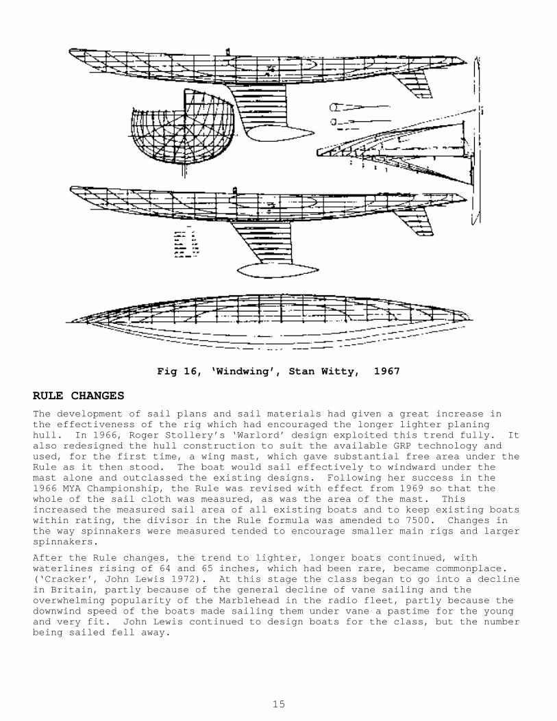
Fig 16, ‘Windwing’, Stan Witty, 1967
RULE CHANGES The development of sail plans and sail materials had given a great increase in the effectiveness of the rig which had encouraged the longer lighter planing hull. In 1966, Roger Stollery’s ‘Warlord’ design exploited this trend fully. It also redesigned the hull construction to suit the available GRP technology and used, for the first time, a wing mast, which gave substantial free area under the Rule as it then stood. The boat would sail effectively to windward under the mast alone and outclassed the existing designs. Following her success in the 1966 MYA Championship, the Rule was revised with effect from 1969 so that the whole of the sail cloth was measured, as was the area of the mast. This increased the measured sail area of all existing boats and to keep existing boats within rating, the divisor in the Rule formula was amended to 7500. Changes in the way spinnakers were measured tended to encourage smaller main rigs and larger spinnakers.
After the Rule changes, the trend to lighter, longer boats continued, with waterlines rising of 64 and 65 inches, which had been rare, became commonplace. (‘Cracker’, John Lewis 1972). At this stage the class began to go into a decline in Britain, partly because of the general decline of vane sailing and the overwhelming popularity of the Marblehead in the radio fleet, partly because the downwind speed of the boats made sailing them under vane a pastime for the young and very fit. John Lewis continued to design boats for the class, but the number being sailed fell away.
15

DESIGN FOR RADIO SAILING Radio 10-rater sailing was originally no more than putting a radio into existing vane designs, and initially ‘Cracker’ was a favourite vehicle for radio in Britain. It soon became evident that however efficient this ‘toothpick and pocket handkerchief’ type of design was to windward under vane, as a radio boat it had disadvantages. The accuracy of trim required to make effective use to windward of the small high aspect sail plan was not possible to obtain under radio; even more important, the loss of the spinnaker on the off wind legs of the radio course was an insuperable disadvantage. The trend in radio boats was to get shorter on the waterline again and to carry more significant areas of sail. Planing performance was demanded and development followed a parallel path to that in the radio Marblehead class, with displacements further reduced, deeper fins and higher ballast ratios. The main emphasis has been on applying the new technology of lightweight construction, carbon fibre masts and mylar sails to the class. There are still wide variations in approach to the design of radio 10-raters, with the concepts reflecting local conditions for which particular boats are intended.
The internationalisation of model yachting which has followed the introduction of radio control has meant that design inputs from France, Sweden and Australia, among other centres have become significant for the first time in the history of its development.
[This paper will eventually be incorporated into a comprehensive history of model yachting in Britain on which the author has been working for some years. It will cover both the technical and social history of the sport and will pay special attention to the inter-relationship between model and full size developments.] Illustration credits:
MAP Plans service/ASP: Figs 7, 9, 10, 16
Ray Brigden: Fig 11
Author’s Collection: remainder
Copyright 1987 Russell Potts
16