office of mediarelations
TRANSCRIPT

STS-32
December 1989
1Rockwell InternationalSpace TransportationSystems Division
Office of Media Relations
PUB 3546-V REV 12-89

CONTENTS
Page
MISSION OVERVIEW .................................................................. 1
MISSION STATISTICS ................................................................. 5
MISSION OBJECTIVES ................................................................ 7
DEVELOPMENT TEST OBJECTIVES ................................................... 7
DETAILED SUPPLEMENTARY OBJECTIVES ............................................ 8
PAYLOAD CONFIGURATION .......................................................... 9
SYNCOM IV-5 ......................................................................... 11
LONG-DURATION EXPOSURE FACILITY ............................................... 17I
IMAX CAMERA ...................................................................... 33
FLUIDS EXPERIMENT APPARATUS .................................................... 35
PROTEIN CRYSTAL GROWTH ......................................................... 37
LATITUDE/LONGITUDE LOCATER .................................................... 43
AIR FORCE MAUl OPTICAL SITE CALIBRATION TEST ................................. 45
MESOSCALE LIGHTNING EXPERIMENT ............................................... 47
AMERICAN FLIGHT ECHOCARDIOGRAPH ............................................ 49
CHARACTERIZATION OF NEUROSPORA CIRCADIAN RHYTHMS ....................... 51
ON-ORBIT DEVELOPMENT TEST OBJECTIVES .......................................... 53
ON-ORBIT DETAILED SUPPLEMENTARY OBJECTIVES .................................. 57

.%
MISSION OVERVIEW
This is the ninth flight of Columbia and the 33rd in the space on the STS 51-1 mission on Aug. 29, 1985, but it failed to operate.transportation system. It is also the first flight launched from During the mission, Syncom F3 was repaired and is operational.Launch Complex 39-A since January 1986.
The exact launch time of Columbia for this mission will be
The flight crew for the STS-32 mission consists of corn- determined by the LDEF's location in Earth orbit 12 hours beforemander Daniel C. Brandenstein; pilot James D. Wetherbee, and the launch.mission specialists Bonnie J. Dunbar, Marsha S. Ivins andG. David Low. The rendezvous with the LDEF includes maneuvers to ensure
that the external tank misses islands near Hawaii after it separates
The primary objectives of this nine-day mission are to deploy from the orbiter and an orbital maneuvering system separationthe Syncom (synchronous communication) IV-5 (or F5) satellite, maneuver following the deployment of Syncom IV-5.rendezvous with the Long-Duration Exposure Facility and retrieveand berth it in Columbia's payload bay for return to Earth, and Columbia nominally will approach the LDEF from the rearacquire data on the flight crew's exposure to long periods of zero (catching up with it). It will then move in front of the LDEEgravity and its effects on landing Columbia. The exposure data above the LDEF, and then down to grapple the LDEF withwill be used as part of the efforts to develop a kit that will allow an Columbia's remote manipulator system and berth it in Columbia'sorbiter to remain in orbit for up to 16 days initially and eventually payload bay.28 days. l
Nominally, the LDEF capture is scheduled to occur on orbitThe LDEF was deployed from Challenger into Earth orbit 49, followed by berthing in Columbia's payload bay on orbit 51
during the STS 41-C mission on April 7, 1984, and is approaching after photographic and television documentation of the LDEE Ifthe end of its orbital lifetime. It has been in orbit in a gravity- a decision is made at launch to delay the nominal retrieval of thegradient, stabilized attitude for five years. LDEF, retrieval could occur on orbits 64 or 80. The documenta-
tion of LDEF's condition before it is berthed is required due to the
Syncom IV-5 is the last in a series of five communications possible effects of atmospheric pressure on the LDEF during entrysatellites for the U.S. Navy. Syncom IV-5 will be deployed from and its five-year exposure to the space environment.Columbia's payload bay, nominally at a mission elapsed time ofday one, zero hours and 44 minutes on orbit 17. Backup deploy- Eight secondary payloads will also be carried aboard Colum-ment opportunities are available on orbits 32, 33, 34, 38 and 48. - bia on this mission.
Syncom F2 was deployed by Discovery on Aug. 31, 1984, The IMAX camera project is a collaboration between theduring the STS 41-D mission and is operational. Syncom FI was National Aeronautics and Space Administration and the Smithso-deployed by Discovery during the STS 51-A mission on Nov. 8, nian Institution's National Air and Space Museum to document1984, and is also operational. Syncom F3 was deployed by Discov- significant space activities using the IMAX film medium. This sys-ery during the STS 51-D mission on April 13, 1985, but its perigee tem developed by the IMAX Systems Corp. of Toronto, Canada,kick motor failed to fire. The mission was extended to allow the uses specially designed 70mm cameras and projectors to recordcrew to use a "flyswatter" technique to fix the PKM, but the and display very high definition, large-screen motion pictures.effort was unsuccessful. Syncom F4 was deployed by Discovery 1MAX will be used on this mission to cover the retrieval of the

LDEF and for Earth viewing. Opportunities for filming will be there are three processes used to grow crystals on Earth--vaporprovided to the flight crew before the flight and in real time. The diffusion, liquid diffusion and dialysis--only vapor diffusion willcamera and supporting equipment are stowed in the middeck, be used in this mission's set of experiments. The PCG experiments
are installed and operated in Columbia's middeck.The Fluids Experiment Apparatus experiment is one of the
first designed specifically to investigate the effects of disturbances The Air Force Maui Optical Site Calibration Test allowson crystal growth processes. The main sources of disturbance to ground-based electro-optical sensors located on Mt. Haleakala onbe investigated are Columbia's engine firings and flight crew exer- Maui, Hawaii, to collect imagery and signature data for Columbiacise on the treadmill, but several other disturbances typical of during cooperative overflights while Columbia performs reactionorbiter operations will be included. This research is expected to control system thruster firings and water dumps or activates pay-provide information useful in establishing the microgravity-level load bay lights. The data are used to support the calibration ofrequirements for processing materials aboard space station Free- AMOS sensors and the validation of spacecraft contaminationdom and a greater understanding of the role of residual gravity in models. This experiment is a continuation of tests made on thematerials processing. This experiment will also investigate the STS-29, 30 and 34 missions.effects of disturbances on the stability of a freely suspended mol-
ten zone and provide information on the impurity-refining capa- . The Characterization of Neurospora Circadian Rhythms inbility of float zone processing in space. The FEA and its corn- Space experiment is to determine if the circadian rhythm (diurnalputer are located in the middeck of Columbia's crew cycle) of neurospora (pink bread mold) persists in the microgravitycompartment, of space. The fundamental question to be addressed by this experi-
In collaboration with the University of Alabama in Birming- ment is whether the conditions of space, especially the absence of 2ham, NASA's Marshall Space Flight Center, Huntsville, Ala., is Earth's strong gravitational field, affect neurospora's circadiancontinuing a series of experiments in protein crystal growth that rhythms. This is a middeck experiment.may be a major benefit to medical technology. These experimentscould improve food production and lead to innovative drugs to The American Flight Echocardiograph experiment iscombat cancer, AIDS, high blood pressure, organ transplant rejec- designed to provide in-flight measurements of the size and func-tion, rheumatoid arthritis, and many other diseases, tioning of the heart and record heart volume and cardiovascular
responses to space flight. Results from the AFE will be used in the
Protein crystal growth experiments were first carried out development of optimal countermeasures for crew members' car-during the Spacelab 2 mission in April 1985 and have been flown diovascular changes. The AFE hardware is located in a middeckon the space shuttle six times. The first four flights were designed locker.primarily to develop hardware and techniques for growing crystalsin space. The STS-26 and 29 experiments were the first scientific The Mesoscale Lightning experiment is designed to obtainattempts to grow useful crystals by vapor diffusion in micrograv- nighttime images of lightning in order to better understand theity. The STS-26 and 29 payloads, unlike those on previous flights, global distribution of lightning events in storms that are closefeatured temperature control and the automation of some of the together and the relationships of lightning, convective storms andprocesses to improve accuracy and reduce the flight crew's time precipitation. Cameras in Columbia's payload bay will recordrequired, lightning directly below Columbia, and if time permits, the flight
crew will also use handheld 35mm cameras to photograph light-During this mission, 120 different PCG experiments will be ning in storm systems not directly below Columbia's ground track.
conducted simultaneously on as many as 24 proteins. Though The MLE has gathered data on STS-26, 30 and 34.

/
The Latitude/Longitude Locater experiment uses a modified gitude and latitude of each of the targets on which the marks are70mm Hasselblad camera with a fixed and moving reticle to make taken. The objective of the experiment is to evaluate the accuracysightings on targets and take angle marks (as well as photographs), and usability of the instrument by viewing and marking on knownA camera-computer interface unit connects the camera to a GRID sites on Earth during the flight.compass computer. The collection of marks is reduced to the Ion-
/
MISSION STATISTICS
Launch: The exact time of launch on a given day is determined by nautical miles (185 by 191 statute miles), then 149 by 166 nan-the LDEF's exact location in Earth orbit, which will not be tical miles (171 by 191 statute miles), then 145 by 149 nauticalknown until 12 hours prior to launch. The launch window vat- miles (166 by 171 statute miles), then 147 by 149 nautical milesies from day to day due to a variety of technical requirements. (169 by 171 statute miles), then 148 by 150 nautical miles (170
by 172 statute miles)
12/18/89 7:29p.m. EST Nominal6:29p.m. CST estimated Space Shuttle Main Engine Thrust Level During Ascent:4:29 p.m. PST launch time 104 percent
Mission Duration: 216 hours (nine days), 21 hours, 35 minutes Total Lift-off Weight: Approximately 4,540,161 pounds
Landing: Nominal end of mission is on orbit 159. Orbiter Weight, Including Cargo, at Lift-off: Approximately229,848 pounds
12/28/89 5:04 p.m. EST Based on4:04 p.m. CST nominal estimated Payload Weight Up: Approximately 26,625 pounds2:04 p.m. PST launch time
Payload Weight Down: Approximately 37,732 pounds
Inclination: 28.5 degrees 5Orbiter Weight at Landing: Approximately 229,285 pounds
Ascent: The ascent profile for this mission is a direct insertion.Only one orbital maneuvering system thrusting maneuver, Payloads: Syncom IV-5 deployment, Long-Duration Exposurereferred to as OMS-2, is used to achieve insertion into orbit. Facility retrieval, Fluids Experiment Apparatus 3, ProteinThis direct-insertion profile lofts the trajectory to provide the Crystal Growth 1II-02, Latitude/Longitude Locater, Ameri-earliest opportunity for orbit in the event of a problem with a can Flight Echocardiograph 02, Characterization of Neuro-space shuttle main engine, spora Circadian Rhythms in Space 01, Air Force Maui Optical
Site 04, Mesoscale Lightning, and IMAX. The FEA, PCG,The OMS-I thrusting maneuver after main engine cutoff plus LLL, AFE, CNCR, and IMAX payloads are located inapproximately two minutes is eliminated in this direct- Columbia's crewcompartment.insertion ascent profile. The OMS-I thrusting maneuver isreplaced by a 5-foot-per-second reaction control system Flight Crew Members:maneuver to facilitate the main propulsion system propellant Commander: Daniel C. Brandenstein, third space shuttledump. flight
Pilot: James D. Wetherbee, first space shuttle flight
Altitude: 161 by 190 nautical miles (I 85 by 218 statute miles), then Mission Specialist 1: Bonnie J. Dunbar, second space shuttle156 by 190 nautical miles (179 by 218 statute miles), then 166 flightby 191 nautical miles (191 by 219 statute miles), then 166 by Mission Specialist 2: Marsha S. lvins, first space shuttle flight167 nautical miles (191 by 192 statute miles), then 161 by 166 Mission Specialist 3: G. David Low, first space shuttle flight

Ascent Seating: Relay Satellite system. It is a high-resolution facsimile systemFlight deck front left seat, commander Daniel Brandenstein that scans text or graphics and converts the analog scan dataFlight deck front right seat, pilot James Wetherbee into serial digital data. Transmission time for an 8.5- by I l-inchFlight deck aft center seat, MS 2 Marsha Ivins page can vary from approximately one minute to 16 minutes,Flight deck aft right seat, MS 1 Bonnie Dunbar depending on the hard-copy resolution desired.Middeck, MS 3 David Low
The text and graphics hard copier operates by mechanicallyEntry Seating: feeding paper over a fiber-optic cathode-ray tube and then
Flight deck aft right seat, MS 3 David Low through a heater-developer. The paper then is cut and stored in aMiddeck, MS I Bonnie Dunbar tray accessible to the flight crew. A maximum of 200 8.5- by I l-
inch sheets are stored. The status of the hard copier is indicatedExtravehicular Activity Crew Members, If Required: by front panel lights and downlink telemetry.
Extravehicular activity astronaut 1 would be David Low andEV 2 would be Bonnie Dunbar. The hard copier can be powered from the ground or by the crew.
Angle of Attack, Entry: 40 degrees Uplink operations are controlled by the Mission Control Centerin Houston. Mission Control powers up the hard copier and
Entry: Automatic mode will be used until subsonic; then control then sends the message. In the onboard system, light-sensitivestick steering mode will be used. paper is exposed, cut and developed. The message is then sent to
the paper tray, where it is retrieved by the flight crew.Runway: Nominal end-of-mission landing will be on lake bed 6
Runway 17 at Edwards Air Force Base, Calif. • The teleprinter will provide a backup on-orbit capability toreceive and reproduce text-only data, such as procedures,
Notes: weather reports and crew activity plan updates or changes, from• The remote manipulator is installed in Columbia's payload bay the Mission Control Center in Houston. The teleprinter uses the
for the retrieval of the LDEF on this mission. The galley is S-band and is not dependent on the TDRS Ku-band. It is ainstalled in the middeck of Columbia. modified teletype machine located in a locker in the crew com-
partment middeck.• The text and graphics system is the primary text uplink and can
only uplink images using the Ku-band. TAGS consists of a fac- The teleprinter uplink requires one to 2.5 minutes per message,simile scanner on the ground that sends text and graphics depending on the number of lines (up to 66). When the groundthrough the Ku-band communications system to the text and has sent a message, a msg rcv yellow light on the teleprinter isgraphics hard copier in the orbiter. The hard copier is installed illuminated to indicate a message is waiting to be removed.on a dual cold plate in avionics bay 3 of the crew compartmentmiddeck and provides an on-orbit capability to transmit text • Five power reactant storage and distribution cryogenic oxygenmaterial, maps, schematics, maneuver pads, general messages, and hydrogen tank sets were installed in Columbia to supportcrew procedures, trajectory and photographs to the orbiter this nine-day mission.through the two-way Ku-band link using the Tracking and Data

MISSION OBJECTIVES
• Deployment of Syncom IV-5 satellite • Secondary payloads-- IMAX
• Rendezvous with and retrieval of the LDEF -- FEA-3-- PCG-IlI-02
• Acquisition of data on flight crew's exposure to long periods of -- LLLzero gravity (nine days) and its effects on landing Columbia. A -- CNCR-01kit is being developed to allow an orbiter to operate in Earth -- AMOS-04orbit for up to 16 days and eventually 28 days. -- MLE
DEVELOPMENT TEST OBJECTIVES
• Cold soak of Columbia's observation windows • Remote manipulator system operating loads and data duringLDEF retrieval
• Ascent wing aerodynamic distributed loads verification onColumbia • Camcorder demonstration
• Entry aerodynamic control surfaces test • RMS direct drive exercise 7
• Ascent structural capability evaluation • TDRS-to-TDRS demonstrations
• Reinforced carbon-carbon life evaluation • Gravity-gradient attitude control
• Entry structural capability • Additional stowage for extended-duration orbiter
• Pogo stability performance • Orbiter experiments-- Shuttle infrared leeside temperature sensing
• Thermal protection system performance of external tank -- Shuttle entry air data system-- Aerothermal instrumentation package
• Shuttle/payload frequency environment
• Cabin air monitoring

DETAILED SUPPLEMENTARY OBJECTIVES
• In-flight salivary pharmacokinetics of scopolamine and • Muscle biopsydextroamphetamine
• Muscle performance• Cbaracterization of airborne particulate matter in shuttle
atmospheres • Influence of weightlessness on baroreflex function
• Intraocular pressure • Variations in supine and standing heart rate, blood pressure andcardiac size as a function of space flight duration and time,
• Delayed-type hypersensitivity postflight
• In-flight aerobic exercise • Documentary television
• In-flight lower body negative pressure • Documentary motion picture photography

PAYLOAD CONFIGURATION
RemoteManipulatorSystem
ffl
l
Ku-BandSyncnmIV-5 Antenna
STS-32 Payload

; /
SYNCOM IV-5
Syncom IV-5 is the last of five communications satellites to fire despite efforts to fix it. Syncom IV-4, deployed from Dis-designed and built by Hughes Communications Services Inc., a covery on the STS 51-I mission on Aug. 29, 1985, failed to operatewholly owned subsidiary of Hughes Aircraft Co., Los Angeles, shortly after it reached geosynchronous orbit. During the mission,Calif. Although NASA's space shuttle manifest refers to the satel- however, Syncom IV-3 was repaired during astronaut extravehicu-lite as Syncom, Hughes calls it Leasat because the satellite will be lar activity and was positioned in geosynchronous orbit above theleased to the U.S. Navy, which awarded Hughes the satellite equator for U.S. coverage at 105 degrees west longitude.contract.
Hughes owns and operates the Leasat network and offers i Illleasing services for worldwide voice and data communications tothe Department of Defense for five years per satellite orbital posi-
tion. The contract allows the Navy, which acts as executive agent lon behalf of the Department of Defense, the option to extend the /lease for up to two years and to purchase the satellites after five
!
years. Users include mobile air, surface, subsurface and fixedEarth stations of the Navy, Marine Corps, Air Force and Army.
The ground segment of Leasat includes Hughes' Operation _Control Center in Los Angeles, Calif.; two movable ground sta- "_o.._tions in Guam and Norfolk, Va.; and five satellite control sites ""_located in Guam, Hawaii, Italy, Stockton, Calif., and Norfolk,Va. Leasat operations are coordinated via dedicated leased terres-trial lines to the Naval Space Command Operations Center inDahlgren, Va.
Syncom IV-2 was deployed from Discovery during the STS41-D mission on Aug. 31, 1984. It was originally positioned ingeosynchronous orbit above the equator at 100 degrees for U.S.coverage but was subsequently repositioned above the equatorover the Atlantic Ocean at 15 degrees west longitude. SyncomIV-1, which was deployed from Discovery in the STS 51-A missionon Nov. 8, 1984, was originally positioned in geosynchronousorbit above the equator over the Atlantic Ocean but was reposi-tioned above the equator over the Indian Ocean at 73 degrees eastlongitude.
When Syncom IV-3 was deployed from Discovery on the
STS 51-D mission on April 13, 1985, its perigee kick motor failed Syneom IV-5, orF5


Syncom IV-5, to be deployed from Columbia on this mis- upon ground command one to 48 days after deployment from
sion, is targeted for geosynchronous orbit above the equator over Columbia, LAM firing by ground command 14 hours after PKMthe Pacific Ocean at 177 degrees west longitude. When it reaches firing and UHF antenna deployment upon ground command.its destination, Syncom IV-5 will complete the system Hughes was
contracted to provide. Originally designed as a ground spare, Syn- These modes can be changed at the prelaunch countdowncom IV-5 has been modified to allow a normal postejection time ofT minus 11 hours.
sequence mode, a subtransfer Earth orbit mode, or a low Earth
orbit mode. Syncom Subtransfer Earth Orbit Sequence
The normal PES mode consists of omnidirectional antenna SEO
deployment 80 seconds after satellite deployment from Columbia, Activity PES Option Option LEO Optionperigee kick motor firing 45 minutes after deployment from Omni PES 80 secondsColumbia, liquid apogee motor firing by ground command 14 antenna after spacecrafthours after PKM firing and UHF antenna deployment upon deployment deploymentground command. PKM firing PES 45 minutes _..
after spacecraft
The SEO mode activity sequence is omni antenna deploy- deploymentment 80 seconds after satellite deployment from Columbia, PKM LAM firing Ground command Ground14 hours after commandfiring 45 minutes after deployment from Columbia, LAM firing PKM 1-20 daysby ground command one to 20 days after PKM firing and UHF after PKM 13antenna deployment upon ground command. UHF antenna Ground command Ground
deployment commandThe LEO mode activity sequence is omni antenna deploy-
ment 80 seconds after deployment from Columbia, PKM firingSyncom Low Earth Orbit Sequence
Syncom Nominal Postejection Sequence SEOActivity PESOption Option LEO Option
SEO Omni PES 80 secondsActivity PESOption Option LEO Option antenna after spacecraft --_'-
Omni PES 80 seconds deployment deployment
antenna after spacecraft PKM firing PES 45 minutes Ground commanddeployment deployment after spacecraft --_,- 1-48 days afterPKM firing PES 45 minutes deployment spacecraft
after spacecraft deploymentdeployment LAM firing Ground command Ground Ground command
_AM firing Ground command 14 hours after command 14 hours after14 hours after PKM 1-20 days PKMPKM after PKM
UHF antenna Ground command UHF antenna Ground command Ground Ground commanddeployment deployment command

The Syncom satellites are the first designed for launch exclu-
sively by the space shuttle because their 14-foot diameter is too Spinning _ I_large for any other launch vehicle. Syncom is a cylindrical satellite Thermal \\\_._c_'"
deployed t'rom the payload bay in a horizontal position. Radiator._._'_
Each satellite is 20 feet, 3 inches long with the UHF and ThermaIBespunL._-J ..omnidirectional antennas deployed. With its antennas stowed in Rarrier----------_..l,_("(:_:-_ )
the launch configuration, the satellite is 14 feet, I inch long. In Spinningorbit with its twin helical antennas extended, Syncom is 25 feet Truss /Oespun_"" Platformlong. Each satellite and its cradle in the payload bay of the space Structure\
shuttle orbiter weigh approximately 17,000 pounds. Weight after BAPTAdeployment from the payload bay is approximately 15,200 j ._pounds, and the weight of each satellite on station at the beginning
of life is approximately 3,060 pounds, i il II'_/Syncom's wide body allows its perigee and apogee kick "-
motors to be designed into the satellite structure. The PKM is a _ i i /solo_
third-stage Minuteman solid rocket motor. Syncom's two kickmotors are fueled by a bipropellant system that wraps around the r
cavity containing the PKM. This concept eliminates the extra _ Ceg ItlllllfIlllltfdl_length of a separate-stage solid-rocket-fuel PKM and reduces Array _lJ/_ _" 14launch cost. _ Hydrazine
Reaction
The deployment of Syncom IV-5 with its unique propulsive ControlSystem
stage from Columbia's payload bay is nominally scheduled at the ff_) aipropellant
mission elapsed time of day one, zero hours and 44 minutes on _ ApogeeKickorbit 17. Backup deployment opportunities are available on orbits MotorSystem32, 33, 34, 38 and 48.
Aft
The Syncom satellite is attached at five contact points (four ThermalIongeron and one keel) to a cradle in Columbia's payload bay. In Barrierpreparation for Syncom deployment, Columbia is oriented so thatSyncom's spin axis is pointed in the direction that its PKM must _-_
thrust. Columbia's attitude is negative Z, local vertical (tail for- ___ Perigeeward and payload bay toward Earth). Locking pins at four of the KickMotor
contact points are mechanically retracted by electrical motors, :_/_i-_-:_._-.'__-'_ PerigeeKickwhich takes about five minutes per pin. A pyrotechnic device at _(_-_.))_ Motorthe fifth contact point is initiated to release a spring that pushes ,._:-_ .... Adapterone side of the satellite up while the other side pivots. This pro-vides Syncom with a separation velocity of 1.5 feet per second and Syncom Satellite

a stabilizing spin of approximately two revolutions per minute, deployed. Forty-five minutes after deployment, the solid-fuelThis simultaneous rotation and translation maneuver (Frisbee PKM is ignited and its spent case is jettisoned. Shortly after peri-concept) also settles the liquid propellants, gee motor firing, the satellite is acquired by one of the Leasat
ground stations. Orbital determination is made, and Syncom isSyncom is a spin-stabilized satellite with a spun portion that configured by ground command for the transfer orbit augmenta-
contains the solar array, sun and Earth sensors for attitude deter- tion maneuvers, which are made with the two liquid apogeemination and Earth-pointing reference, batteries for eclipse opera- motors. The first of three such maneuvers raises the apogee totion, and all propulsion and attitude control hardware. The de- 10,800 nautical miles, the second raises the apogee to 14,300 nauti-spun platform contains the Earth-pointing twin helical antennas, cal miles, and the third achieves synchronous orbital altitude. Atcommunication repeaters, and the majority of the telemetry, this point, Syncom is in a transfer orbit with a 160-nautical-miletracking and command equipment, perigee and a 19,300-nautical-mile apogee. The final maneuver by
the LAMe circularizes the orbit with a planned 3-degree incline-
The satellite's solar drum generates about 1,200 watts at the tion to the equator at geosynchronous altitude.end of seven years. Three 25-ampere-hour nickel-cadmium batter-
ies provide electrical power for eclipse operations. Twelve UHF The LAMe are 100-pound-thrust, hydrazine-fueled apogeechannels operating in the range of 240 to 400 MHz provide Syn- kick motors. A hydrazine reaction control system and smallcom's main communication capability, thrusters provide Syncom's orbit and attitude control.
Upon nominal deployment, Syncom's power is turned on, Fifteen minutes after the satellite's deployment, Columbiaand 80 seconds after deployment the omnidirectional antenna is performs an orbital maneuvering system separation maneuver at
18 feet per second, resulting in a nominal 166- by 191-nautical- 15(__._/Outrigger
(PusboffSide)• __L ReorientedandSpring I_l "_'_..""",_-_'STS Signal 5.Spacecraft
_ Apogee Motor
Aft _ Cartr,dge.....,_.._.v Interface _ _ _Fired.... _ Cradle _,-,,./..._ _ /" / 6. Spacecraftonf=r_// _[// _/_
Mechanisms(4) .Adjustable / /_1 u / //// _ ;_I;;_ _ G ])N_l__ ,e,_/ Tr"nni°" / /_/ / 2.Spacecraft/.._ F_mSTS /'c1_ ) ]_-_ _,_ . STSPowerand / //l/ / TurnedOn'X._--...__ /" ";'\ I / / k
I 7.Orb,....Touchap'"- - h/f_.. "J_= 4_e,igeaCane"\'-,_ /Signallnterfaces / /_Outrigger_"r_. _-Q"_" / //f/' _ and Drift Stop . (l[( _ _"_= Z S/epar_ted
(Pivot'_;ide) _:;...L'_ j _ / /f'J'7 _ 3.Per,gee ,:.:,_(_._ /STS Parking_//
_ _ SynchronousOrbit /
Trunmons(4) g_ ___[3_'-'_s(2_"_-'_'-_'_ "_'" KeelTrunnion _ _ 19,300NauticalMiles /_,_:_ 8, PayloadOespunand
_._. UUH_FHFAetennaDeplo,ed
Syncom Cradle in Columbia's Payload Bay Syncom Launch Sequence

mile orbit. Twenty-nine minutes after Syncom's deployment,Columbia is maneuvered to protect its windows from the firing ofthe satellite's solid rocket perigee kick motor, and Columbia'sremote manipulator system is positioned so that its wrist televisioncamera can film the motor's thrusting.
16

%
/
LONG-DURATION EXPOSURE FACILITY
The Long-Duration Exposure Facility is essentially a free- The launch of Columbia will be determined by LDEF's exactflying cylindrical structure for experiments that required long- location in orbit, which will not be determined until 12 hoursterm exposure to the space environment, before the launch.
The LDEF is carrying 57 science and technology experimentsinvolving approximately 200 investigators from the United Statesand eight other countries. It could have accommodated 86 experi-ment trays, 72 around its circumference and 14 on the two ends.
The LDEF was built by NASA's Langley Research Center inHampton, Va. It is a 12-sided, open-grid structure made of alumi-num rings and longerons (fore and aft framing members). TheLDEF is 30 feet long and 14 feet in diameter and weighs approxi-mately 8,000 pounds. The combined weight of the structure andthe 57 experiments on board is approximately 21,400 pounds.
The LDEF was deployed into Earth orbit from Challengeron the STS 41-C mission on April 7, 1984. Originally, the LDEFwas to be retrieved in February 1986, but the loss of Challenger in 17January 1986 and return-to-flight activities delayed the retrievaluntil this mission.
The LDEF has remained on orbit in a gravity-gradient, stabi-lized mode. Everything is in the same position on the LDEF as itwas when the facility was deployed.
The experiments on the LDEF are organized in four catego-ries: materials, coatings and thermal systems; power and propul-sion; science; and electronics and optics.
Trays for mounting experiment hardware to the periphery ofthe LDEF structure are 34 inches wide and 50 inches long. Traysfor mounting hardware on the end frames are smaller--34 inchessquare. The trays are 3, 6 or 12 inches deep depending on therequirements of the experiments. Experiments in the peripherytrays weigh 180 pounds, while the end tray experiments weigh200 pounds. Long-Duration Exposure Facility in Earth Orbit

10,000
15,000
20,000 18
TargetCenterof
RotatingLocalVertical,Local Phased25,000 HorizontalReferenceFrame Elapsed
Time
StarTracker Day/Night (Hr:Min___._) Event
30,000 - _ Night -3:47 NormalHeightAdjustmentManeuver-3:03 NormalCorrectiveManeuver
-3:00 StarTrackerNavigation
RadiusBarVector -1:30 StarTrackerNavigation
TowardEarth -0:57 NormalCorrectiveCombinationManeuver
-0:49 RendezvousRadarNavigation
0:00 TerminalPhaseInitiation
FinalSetofTargetingTowardLDEF
LDEF Rendezvous Profile

0-10,000 -20 000 -30 000 -40,000 -60,000 -70,000
Velocity 7 Q FeetVectorOirectionofOrbitalTravel
5,000
®
10,000
StarTracker19
k _ Night_ .E
15,000- "_m
_ == TargetatCenter-_ __° _= ,=,A '_ _ of RotatingLocalVertical,_ ._ -'" ,,,_ LocalHorizontal_ a=_' _ o__ ._ EventDescription ,._ . _ _, r
.... '= j_ . _rame
20,000 _ +00:00 (_ TerminalInitiationBurn_ +00:02 TI _ RendezvousRadarNavigation
(andStarTrackerNavigation,If Required)
+00:21 MC1 (_ MidcourseCorrection1+00:27 (_ RendezvousRadar-OnlyNavigation
Radius .,. +00:36 OOPN (_) Out-of-PlaneNulIManeuverBarVector +00:48 MC2 _ MidcourseCorrection2
TowardEarth +00:58 MC3 _ MidcourseCorrection3+01:08 MC4 (_) MidcourseCorrection4+01:10 _) BeginManualPhase+01:13 (_) CrossRadiusBar
LDEF Rendezvous Profile

The rendezvous with the LDEF requires maneuvering toensure the external tank misses islands near Hawaii and perform- (_)
ing the orbital maneuvering system separation maneuver after (_)Syncom IV-5 is deployed. -200
In a nominal rendezvous, Columbia will approach the LDEFfrom the rear (catching up with the LDEF). The orbiter will then Feet -100
move in front of the LDEE above it and down to grapple the ._ _ _ ,_ _LDEF with the remote manipulator system and berth it in the pay- ..,,.. _ u_ _ _load bay. Velocit_
VectorDirection
Nominal LDEF capture with the RMS is scheduled to occur of Orbital 100on orbit 49, followed by berthing in Columbia's payload bay on Travelorbit 51 after photographic and television documentation of theLDEE If it is decided at launch to delay the nominal retrieval of 200the LDEF, it could be retrieved on orbits 64 or 80. The LDEF's
condition must be documented before it is berthed due to the pus- 300sible effects of atmospheric pressure on it during entry and its five-year exposure to the space environment. During the documenta-tion period, Columbia's upward-firing reaction control system TargetatCentarofRotating 400thrusters will be inhibited. It will take approximately three orbits LocalVertical,LocalHorizontal 20to complete the documentation. ReferenceFrame 500
Columbia's rendezvous sequence is automated until theorbiter is within approximately 10 miles of the LDEE Then the _ Night 600flight crew switches to manual control. Columbia's rendezvousradar, which is part of the Ku-band system, is used to skin-track Feet
the LDEE The Ku-band antenna is gimbaled, which permits it to Radiusradar search for the LDEE Before the radar search begins, BarVect0rColumbia gives the Ku-band system the general location of the , TowardEarthLDEE The radar makes a spiral scan of up to 60 degrees to search
for the LDEF and pinpoint its location. The radar detects the RendezvousDay/Night Time EventDescriptionLDEF by bouncing a radar beam off tile LDEF's surface in apas- Radar (Hr:Min)
sive mode. When the rendezvous radar models no longer T _ +1:35 _CrossVelocityDar
required, the Ku-band system is switched to the communication +1:58 EstablishRadiusBarmode. +2:02 RadiusBarApproachJ
I +2:31 TargetCaptureThere are two grapple fixtures on the LDEE The grapple fix-
ture on the starboard side and an adjacent chevron are part of theLDEF experiment initiation system, which was used when the Proximity Operations

Feet LDEF was deployed. The grapple fixture on the port side, without
,___- -400 a chevron, is a standard grapple fixture. For the nominal retrieval
VelocityVector of the LDEF, the port grapple fixture will be used; however, either(V)Direction --200 one could be used.ofOrbital
Travel . I I I _ I I I I I I The LDEF has two side support trunnions on its port andFeet 1,000 800 6007/400 200 -200 -400-600-800 -1,000 starboard sides and a keel trunnion for berthing it in Columbia's
/I -- 200 payload bay. The side support trunnions will mate with the pay-27:00 PET / _ -- - 400 load retention latch assemblies on Columbia, and the LDEF's keel
V-BarArrivalat400 Feet trunnion will mate with a keel payload retention latch assembly onNullClosingRate -- 600 the orbiter.
- 12:00PET_Switchto Luw-Z _" -- -- 800 The five active payload retention latch assemblies (four Ion-
geron and one keel) are controlled by dual-redundant alternatingat 800 Feetj -- -- 1,000 current electric motors, which release or latch the assemblies. The
10 O0PET--: active retention latch assemblies are controlled from Columbia's1,000 Feet -- -- 1,200Braking
Gate _ -- -- 1,400 - 51:00 PET
6 O0PET/-- Feet YawOrbiter-- : - 50:00 PET ToAlignRMS1,500Feet _ -- -- 1,600 ArriveR-Bar;NullRates WithGrappleFixture 2 ILocalVertical,
BrakingGate - -- 1,800O0 BeginRBarApproach
- -- 2,000 Sunset-.-.-=,.-- 4:00PET /2,000 Feet -- 2,200 InertialFlyaround -200BrakingGate
--- 2,400 - 27:00 PET _ _ - 1'.19.00Phased•
V.BarArrivalat400 Feet -100 ElapsedTimeIPET)
-- 2,600 NullClosingRate Range- 35;NullRatesj GrappleLOEF
-2,80o I I I I IO:O0PhaseElapsed Velocity 500 300 200 100 -lO0 -200
VectorIV)
000 Time(PET)Manual Direction FeetTakeoverofRendezvous ofOrbital -- tO0
_ _ 3,200/at MC4+ 2 Minutes Travel
-- -3,400 - 200Radius(HIBar
Radius(R)Bar VectorTowardEarthVectorTowardEarth
Proximity Operations Proximity Operations

aft flight deck control panel A6U. On this mission, the five reten- AutomaticSequencePosition
tion latch assemblies are opened after Coh,mbia is on orbit onthefirstday of the mission. 1 ___.
Positioning a payload retention latches switch to release pro,vides ac power to the dual electric motors associated with theretention latch of the selected payload, driving the retention latch
open. The operating time of the latch with both motors operating 2 / / ('_ /'-7is 30 seconds; with only one motor operating it is 60 seconds. Thelalkback indicator immediately above a retention latches switchindicates rel when the latch is fully open. There are two micro-switches for the rel talkback indication; however, only one is
requiredtocontrolthetalkbackindicator. Thepayloadretention 3 _C..._3_,__
latches ready for latch talkback indicator of a retention latchesswitch is barberpole when the payload latch is set in the releaseposition. There are two microswitches for the ready-for-latchtalkback indication; however, only one is required to control thetalkback indicator.
Upon completion of the documentary photography and tele-vision, the RMS berths the LDEF in Columbia's payload bay. The _.r 22keel active retention latch centers the LDEF in the yaw direction.It can float plus or minus 2.75 inches in the X direction and must
be latched closed before the longeron latches are closed. The four 5/_longeron latches and the keel latch must be latched closed toreturn the LDEF to Earth.
Positioning a payload retention latches switch to latch pro-
vides ac power to the dual electric motor associated with the latch _/_
of the payload selected, driving the retention latch closed. The 6operating time of one or both motors is the same as for releasing apayload. A barberpole talkback indicator immediately above eachretention latches switch indicates that latch is ready to latch. Theindicator shows lat when the latch is closed. There are two micro-
switchesforthelatindication;however, oneisrequiredtocontrol 7_ _.._
the talkback indicator. The payload retention latches ready forlatch talkback indicator for a retention latches switch is gray whenthe payload latch is ready to latch.
LDEF Photo Survey Positions

Zt
12 12Aft Starboard
11 1 Lonoeron 1 11FittinginPayloadBay
Forward J
AftPort 10 AO201 A0015 Starboard 2 J A0201 10Longeroo Longeron S1O01 MOO0IFitting Fitting I A0023 ForwardPort
inPayload G10 G12 G2 inPayload H1 i H11 LongeronFittingBay Bay oPaygadBay
]_//_._ Damper
H3 23
Leadin IEdge I Edge EdgeonOrbit SO001 AOi 39-A SO001 onOrbit SO00t AO038 AO133 onOrbit
I I8 I 4 4 8
G8 G6 G4 H5 H6 H7
7 5 5 7
EndFacing EndEarthonOrbit FacingSpace
(AftinPayloadBay) (ForwardinPayloadBay) onOrbitKeelFitting KeelFitting
LDEF Experiments Panel Configuration Located on Ends of LDEF

A B C D E Fjh.
1 A0175 S0001 _ Grapple A0178 S0001 S0001N%
co _ A0189 PO004
2 A0178 S0001 __ _ ¢::= S0001 A0178 e._ PO006Trailing < .,= _ Port A0172EdgeOn TrunnionOrbit _ A0034 _ • MOO03 ¢::=
3 A0187 A0138 _ --A0114 __ [MOO02 _ A0187 S0001
> 4 A0178 A0054 S0001 MOO03 S0001 A0178
-- _ A0044 '05 S0001 A0178 A0178 A0178 S0050 • • S0001 _.
.E "- A0135_ _ _ $1003
.= 6 S0001 S0001 A0178 _ D S0001 _ ¢_ _ A0038 ='_"=- ,,¢ ,_ _ M0002 = :24
"=' 7 A0175 A0178 S0001 A0178 S0001 S0001 _..=_
_ A0056 -_-8 A0171 S0001 A0178 MOO03 A0187 MOO04
Leading AO147 ll_ ==_EdgeOnOrbit _ A0034 _ Starboard MOO03
9 S0069 S0010 A0134 m- _ S0014 A0076iI_ _ A0114 _ Trunnion I• M0002
10 A0178 $1005 Grapple® A0054 AOt78 S0001
11 A0187 S0001 A0178 A0178 S0001 S0001
_ IA001912 S0001 A0201 S0109 _ A0038 $1001
A0180
LDEF Experiments Pane/Configuration

/
LDEF Documentation via Photography�Television Prior to Berthing
Panel Experiment Required Panel Experiment RequiredNo. No. Observation No. No. Observation
1A AO 175 Note fading or color changes of black matte 3A AO 187 Is each canister closed as expected?
finish. Is yellow printing evident? 3B A0138 Are three canisters closed as expected? Note1B SO001 Note discoloration or dissimilarity in color whether thermal cover is intact. Note any
with other debris trays. Note any evidence of splits or tears.impacts. 3C A0023 Note if foil surfaces are intact.
1C Grapple Note any degradation in block chevron A0034 Note any deviation from uniform color of alu-painted on tray. minum cover plate.
1D AO 178 Note whether thermal cover is intact. Note AO 114 Note any deviation in color of white-paintedany splits, tears or unusual edge conditions, cover plate and in color of black insert in oneNote any variations in reflectivity, quadrant.
1E SO001 Note any discoloration or dissimilarity in color A0201 Note any deviation from uniform color ofwith other debris trays. Note any evidence of anodized aluminum cover plate. Note any mir-
rorlike surface sensors that differ fromimpacts, others.
1F SO001 Note any discoloration or dissimilarity in colorwith other debris trays. Note any evidence of 3D MOO03 Note whether larger thin foils are intact. Noteimpacts, general condition of other test specimens.
2A AO 178 Note whether thermal cover is intact. Note MOO02 Note any degradation/discoloration of white-any splits, tears or unusual edge conditions, painted surfaces.Note any variations in reflectivity. 3E S1002 Note whether canister is closed as expected. 25
2B S0001 Note any discoloration or dissimilarity in color Note condition of anodized aluminum cover.with Other debris trays. Note any evidence of A0187 Note any apparent degradation in mirrorlikeimpacts, surface.
2C AO015 Note any discoloration or variation in color on 3F SO001 Note any discoloration or dissimilarity in colorwhite canisters or aluminum base plate. Note with other debris trays. Note any evidence ofcondition of thermal cover in canister, impacts.
AO 187 Note any degradation in mirrorlike surface. 4A A0178 Note whether thermal cover is intact. NoteMOO06 Note whether canister is closed as expected, any splits, tears or unusual edge conditions.
Note any variations in reflectivity.2D AO 189 Note any degradation in white-painted diago-
nal thermal control stripes. 4B A0054 Note any degradation to aluminized Kapton.AO 172 Note any discoloration in white-painted ther- 4C SO001 Note any discoloration or dissimilarity in color
mal cover, with other debris trays, Note any evidence ofSO001 Note any discoloration or dissimilarity in color impacts.
with other debris trays. Note any evidence of 4D MOO03 Note whether canister is closed as expected.impacts. Note the condition of aluminum cover. Note
2E AO 178 Note whether thermal cover is intact. Note any discoloration of white paint.
any splits, tears or unusual edge conditions. 4E SO001 Note any discoloration or dissimilarity in colorNote any variations in reflectivity, with other debris trays. Note any evidence of
2F PO006 TBS impacts.P0004 Note whether thermal cover is intact. Note 4F AO 178 Note whether thermal cover is intact. Note
any splits, tears or unusual edge conditions, any splits, tears or unusual edge conditions.Note any variation in reflectivity. Note any variations in reflectivity.

LDEF Documentation via Photography Prior to Berthing (ConO
Panel Experiment Required Panel Experiment RequiredNo. No. Observation No. No. Observation
5A SO001 Note any discoloration or dissimilarity in color 6F A0038 Note any discoloration in white-painted basewith other debris trays. Note any evidence of plate and tray walls.
impacts. 7A AO 175 Note any fading or color change of black5B A0178 Note whether thermal cover is intact.Note matte finish. Is yellow printing still evident?
any splits, tears or unusual edge conditions. 7B A0178 Note whether thermal cover is intact. NoteNote any variations in reflectivity, any splits, tears or unusual edge conditions.
5C AO 178 Note whether thermal cover is intact. Note Note any variations in reflectivity.
any splits, tears or unusual edge conditions. 7C SO001 Note any discoloration or dissimilarity in colorNote any variations in reflectivity, with other debris trays. Note any evidence of
PO005 TBS impacts.
5D A0178 Note whether thermal cover is intact. Note 7D A0178 Note whether thermal cover is intact. Noteany splits, tears or unusual edge conditions, any splits, tears or unusual edge conditions.Note any variations in reflectivity. Note any variations in reflectivity.
5E A0044 Note any variation in color of anodized alumi- 7E SO001 Note any discoloration or dissimilarity in colorS0050 hum sunscreens, with other debris trays. Note any evidence ofAO 135 impacts.
5F S0001 Note any discoloration or dissimilarity in color 7F S0001 Note whether thermal cover is intact. Notewith other debris trays. Note any evidence of any splits, tears or unusual edge conditions.impacts. Note any variations in reflectivity.
266A S0001 Note any discoloration or dissimilarity in color 8A AO171 Note any thin films or foils that may not be
with other debris trays. Note any evidence of intact.
impacts. 8B S0001 Note any discoloration or dissimilarity in color6B SO001 Note any discoloration or dissimilarity in color with other debris trays. Note any evidence of
with other debris trays. Note any evidence of impacts.
impacts. A0056 Note any discoloration in anodized aluminum6C A0178 Note whether thermal cover is intact. Note cover plates.
any splits, tears or unusual edge conditions. A0147 Note any discoloration in white-painted coverNote any variations in reflectivity, plate.
PO003 TBS 8C A0178 Note any discoloration or dissimilarity in color6D SO001 Note any discoloration or dissimilarity in color with other debris trays. Note any evidence of
with other debris trays. Note any evidence of impacts.
impacts. 8D M0003 Note whether canister is closed as expected.A0201 Note any deviation from uniform color of Note condition of aluminum cover. Note any
anodized aluminum cover plate. Note any mir- discoloration of white paint.rorlike surface sensors that differ from others.
8E A0187 Note any degradation in mirrorlike surface.6E A0023 Note if foil surfaces are intact. Red substrate may be visible.
$1006 Note any degradation in test specimens. 8F M0004 Note any discoloration in aluminum and whiteS 1003 Note any deviations in uniform color of cover base and cover plates. Note any change in
plate, color or other degradation in fiber-opticMOO02 Note whether aluminized Kapton thermal samples.
cover is intact.
i
,2

LDEF Doc,tmentation via Photography Prior to Berthing (ConO
Panel Experiment Required Panel Experiment RequiredNo. No. Observation No. No. Observation
9A S0069 Note position of carousel. Note which, if any, 11A A0187 Note any discoloration or marks on pure alu-test specimens are visible, minum panels.
9B SO010 Note whether canister is closed as expected. 11B S0001 Note any discolorations or dissimilarity inNote condition of anodized aluminum cover color with other debris trays. Note any evi-plate, dence of impacts.
AD 134 Note any foils or specimens that may not be 11C AO 178 Note whether thermal cover is intact. Noteintact, any splits, tears or unusual edge conditions.
9C A0023 Note if foil surfaces are intact. Note any variations in reflectivity.
A0134 Note any deviation from uniform color of alu- 11D A0178 Note whether thermal cover is intact. Noteminum cover plate, any splits, tears or unusual edge conditions.
AO 114 Note any deviation in color of white-painted Note any variations in reflectivity.cover plate and black insert in one quadrant. 11 E SO001 Note any discoloration or dissimilarity in color
A0201 Note any deviation from uniform color of with other debris trays. Note any evidence ofanodized aluminum cover plate and any mir- impacts.
rorlike surface sensors that differ from others. 11F SO001 Note any discoloration or dissimilarity in color9D MOO03 Note whether large foils are intact. Note gen- with other debris trays. Note any evidence of
eral condition of other test specimens, impacts.
MOO02-1 Note any degradation or discoloration in 12A SO001 Note any discoloration or dissimilarity in colorwhite-painted surfaces, with other debris trays. Note any evidence of 27
9E SO014 Note any variations in black-painted face impacts.plate. 12B A0201 Note any deviation from uniform color of
9F A0076 Note any loose foil surfaces or strips, particu- anodized aluminum cover plate. Note any mir-lady around squares located in lower left and rorlike surface sensors that differ from others.lower right of tray. Note whether cover is 12C SO 109 Note any discoloration in aluminum and whiteintact. Note any splits, tears or unusual edge base and cover plates. Note any change inconditions. Note any variations in reflectivity, color or other degradation in fiber-optic
10A AO 178 Note whether thermal cover is intact. Note samples.any splits, tears or unusual edge conditions. 12D A0023 Note if foil surfaces are intact.
Note any variations in reflectivity. AO 180 Note any test specimens that are not intact.10B S1005 Note any discolorations or variations in reflec- Note any variations in color.
tivity of surfaces. AO019 Note general condition of test specimens and
10C Grapple Note condition/state on intro indicators. Note whether temperature tabs are intact.any variation in color of anodized aluminum 12E A0038 Note any discoloration in white-painted basebase plate, particularly around target, plate and tray walls.
10D A0054 Note any degradation of aluminized Kapton. 12F S0001 Note any loose foil surfaces or strips, particu-
10E A0178 Note whether thermal cover is intact. Note larly squares located in lower left and lowerany splits, tears or unusual edge conditions, right of tray. Note whether cover is intact.Note any variations in reflectivity. Note any splits, tears or unusual edge condi-
tions. Note any variations in reflectivity.I OF S0001 Note any discoloration or dissimilarity in color
with other debris trays. Note any evidence ofimpacts.

LDEF Documentation via Photography Prior to Berthing (ConO
Panel Experiment Required Panel Experiment RequiredNo. No. Observation No. No. Observation
10G A0201 Note any deviation from uniform color of 1H $1001 Note any abnormal appearance of 4 solaranodized aluminum cover plate and any mir- panels.rorlike surface sensors that differ from others. 12H M0001 Note whether thermal covers "areintact. Doc-
12G A0056 Note any discoloration in anodized aluminum ument by sketch any deviation in thermaland white-painted cover plates, cover's condition.
AO172 Note any discoloration in white-painted ther- 11H A0201 Note any deviation from uniform color ofreal cover, anodized aluminum cover plate. Note any mir-
M0002-1 • Note any degradation or discoloration in rorlike surface sensors that differ from others.white-painted surfaces. A0023 Note if foil surfaces are intact.
AO147 Note any discoloration in white-painted cover 3H MOOO1 Note whether thermal covers are intact. Doc- 28plate, ument by sketch any deviation in thermal
2G AO015 Note any discoloration or variation in color in cover's condition.
aluminum canisters or base plate. 9H A0038 Note any discoloration in white-painted base8G S0001 Note any discoloration or dissimilarity in color plate and tray walls.
with other debris trays. Note any evidence of 5H SOO01 Note any discoloration or dissimilarity in colorimpacts, with other debris trays. Note any evidence of
6G AO 139-A Note any discoloration in white thermal impacts.
cover. 6H A0038 Note any discoloration in white-painted base4G S0001 Note any discoloration or dissimilarity in color plate and tray walls.
with other debris trays. Note any evidence of 7H AO 133 Note any foils or test specimens that are notimpacts, intact. Note any variations in color of black
face plate.

Radar Rendezvous Range
Passive Skin Track
Range 100 Feel to 12 Nautical Miles (14 Statote Miles)
RangeRate 148 FeetperSecondOpeningMaximumto 75 FeetperSecondClosingMaximum
Active(Transponderon Ihe VehicleBeingTracked)
Range 100 Feet to 300 Naotical Miles (345 Statute Miles)
Range Rate 1.500 Feet per Second Opening Maximum
to 300 Feet per Second Closing Maximum
The shuttle pregnant has not basetined a transponder;however, TRW has a transponder that can be placed on a payload
29
"J t /Optional
Ku-Oand
Deployed /
Assembly_
Ko Band
Radar/
Bay
// Zo332,-,'_.,_._ _ / erecesso,
Ku-Band Radar System

Gear
ePin
SillLongeron 3 Payload
BridgeFitting
30
MainFrame
StabilizerFilling Active Payload Retention Latch
Z Loads_t I_ If the keel latch is not working properly, Columbia could
_ reboost the LDEF approximately 45 nautical miles above the alti-tude it was retrieved at.
The LDEF was designed to be reusable, and repeat missions
with new complements of experiments were planned for thestructure.
KeelFitting
Y Loads LDEF's center ring frame and end frames are welded andbolted aluminum (6061-T6). The longerons are bolted to both
Active Payload Retention System frames, and intercostals (cross pieces positioned between the main
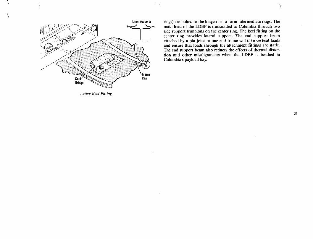
LinerSupports rings) are bolted to the longerons to form intermediate rings. The
_ : _i t_k'_,/V/_'t. -_">'- '_x2'_ ___ __j_ main load of the LDEF is transmitted tO Columbia through two____ side support trunnions on the center ring. The keel fitting on the
_/__ _ , center ring provides lateral support. The end support beamiiiii attached by a pin joint to one end frame will take vertical loads
_:_ _ and ensure that loads through the attachment fittings are static.
The end support beam also reduces the effects of thermal distor-
S_ ::_g: tion and other misalignments when the LDEF is berthed in
Columbia's payload bay.
Active Keel Fitting
31
0_
n
IMAX CAMERA
The IMAX project is a collaboration between NASA and the missions was used as the basis for the IMAX production, "TheSmithsonian Institution's National Air and Space Museum to doc- Dream Is Alive."ument significant space activities using the IMAX film medium.This system, developed by the IMAX Systems Corp. of Toronto, On STS 61-B, an IMAX camera mounted in the payload bayCanada, uses specially designed 70mm cameras and projectors to " recorded extravehicular activities involving space constructionrecord and display very high definition, large-screen color motion demonstrations.pictures.
The IMAX camera, last carried on STS-34, will be used onIMAX cameras have been flown on space shuttle missions this mission to cover the retrieval of the LDEF and to gather mate-
STS 41-C, 41-D, 41-G, 29 and 34 to document crew operations in rial on the use of observations of the Earth from space for 1MAXthe payload bay and the orbiter's middeck and flight deck as well films to succeed "The Dream Is Alive."as to film spectacular views of space and Earth. Film from those
33

FLUIDS EXPERIMENT APPARATUS
Materials are processed in space because crystals superior to will provide information on the impurity-refining capability ofthose grown on the ground have been produced in the low gravity float zone processing in space.levels achievable in low Earth orbit. The focus of the Fluids
Experiment Apparatus 3 experiment, called the Microgravity Dis- Rockwell International Corp.'s Space Transportation Sys-turbances experiment, is to investigate the effects of both orbiter- terns Division, Downey, Calif., is engaged in a Joint Endeavorand crew-induced disturbances in the microgravity environment of Agreement with NASA's Office of Commercial Programs to con-the resulting microstructure of indium crystals grown using the duct floating zone crystal growth and purification research. Thefloat zone technique, agreement, signed on March 17, 1987, provides for microgravity
experiments to be performed on two space shuttle missions in theThe FEA-3 experiment is one of the first experiments company's microgravity laboratory, the FEA.
designed specifically to grow crystals during known disturbancesin order to investigate their effects on crystal growth processes. Under the sponsorship of NASA's Office of CommercialThe main sources of the disturbances to be investigated in this Programs, the FEA will be flown on Columbia on STS-32. STSDexperiment are orbiter engine firings and crew exercise on the is responsible for developing the FEA hardware and integratingtreadmill, but several other disturbances typical of orbiter opera- the experiment payload. NASA's Lyndon B. Johnson Space Cen-tions will be included. This research is expected to provide infor- ter, Houston, Texas, developed the materials science experimentsmarion useful in establishing the microgravity-level requirements and will analyze their results.
for processing materials aboard space station Freedom and will 35also provide a greater understanding of the role of residual gravity The Indium Corporation of America, Utica, N.Y., is collabo-in materials processing, rating with NASA in developing and analyzing the experiments
and is providing the seven indium samples to be processed on theIn addition, this experiment will investigate the effects of dis- FEA-3 mission. NASA will provide standard space shuttle flight
turbances on the stability of a freely suspended molten zone and services under the JEA.

PROTEIN CRYSTAL GROWTH
In collaboration with the University of Alabama in Birming- Protein crystals grown on Earth are often small and flawed.ham, NASA's Marshall Space Flight Center, Huntsville, Ala., is The problem associated with growing these crystals is analogouscontinuing a series of experiments in protein crystal growth that to filling a sports stadium with fans who all have reserved seats.may prove to be a major benefit to medical technology. Once the gate opens, people flock to their seats and, in the confu-
sion, often sit in someone else's place. On Earth, gravity-drivenThese experiments could improve food production and lead convection keeps the molecules crowded around the "seats" as
to innovative drugs to combat cancer, AIDS, high blood pressure, they attempt to order themselves. Unfortunately, protein mole-organ transplant rejection, rheumatoid arthritis and many other cules are often content to take the wrong places in the structure.diseases. Protein crystal growth experiments were first conductedduring the Spacelab 2 mission in April 1985 and have been flown As would happen if you let the fans into the stands slowly,six times. The first four flights primarily were designed to develop microgravity allows the scientist to slow the rate at which mole-techniques and hardware for growing crystals in space. The cules arrive at their places. Since the molecules have more time toSTS-26 and 29 experiments were the first scientific attempts to find their spots, fewer mistakes are made, creating better andgrow useful crystals by vapor diffusion in micogravity. The STS- larger crystals.26 and 29 payloads, unlike those on previous flights, featured tem-perature control and the automation of some of the required pro- Shortly after the shuttle reaches orbit, either mission special-cesses to improve accuracy and reduce the flight crew's time. ists Marsha Ivins or David Low will combine each.of the protein
solutions with other solutions containing a precipitation agent to 37During this mission, 120 different PCG experiments will be form small droplets on the ends of double-barreled syringes posi-
conducted simultaneously, using as many as 24 different proteins, tioned in small chambers. Water vapor will diffuse from eachThough there are three processes used to grow crystals on Earth'-- droplet to a solution absorbed in a porous reservoir that lines eachvapor diffusion, liquid diffusion and dialysis--only vapor diffu- chamber. The loss of water in this vapor diffusion process will pro-sion will be used in this set of experiments. The PCG is installed duce conditions in the droplets that cause protein crystals to grow.and operated in Columbia's middeck.
In three of the 20-chambered, 15- by 10- by 1.5-inch trays,Protein crystals, like inorganic crystals, such as snowflakes, crystals will be grown at room temperature (22 C); the other three
are structured in a regular pattern. With a good crystal roughly the trays will be refrigerated (at 4 C) during crystal growth. STS-32size of a grain of table salt, scientists are able to study the protein's will be the first mission during which PCG experiments will be runmolecular architecture, at 4 C, making it possible to crystalize a wider selection of pro-
teins. The STS-32 mission also provides more time for crystals toDetermining a protein crystal's molecular shape is an essen- grow.
tial step in several phases of medical research. Once the three-dimensional structure of a protein is known, it may be possible to A seventh tray will not have temperature control. The crewdesign drugs that will either block or enhance the protein's normal will videotape droplets in the tray to study the effects of orbiterfunction within the body. Though crystallographic techniques can maneuvers and crew activity on droplet stability and crystalbe used to determine a protein's structure, this powerful technique formation.has been limited by problems encountered in obtaining high-quality crystals well ordered and large enough to yield precise Just before descent, a mission specialist will photograph thestructural information, droplets in the room temperature trays. Then all the droplets and

any protein crystals grown will be drawn back into the syringes, The STS-32 industry, university and government PCGwhich will then be resealed for reentry. After the landing, the hard- research investigators include CNRS, Marseille, France; Eli Lillyware will be turned over to the investigating team for analysis. & Co.; the U.S. Naval Research Laboratory; Du Pont de
Nemours & Co.; Merck Sharp & Dohme Laboratories; TexasTo further develop the scientific and technological founda- A&M University; the University of Alabama in Birmingham/
tion for protein crystal growth in space, NASA's Office of Corn- Schering Corp.; Yale University; the University of Pennsylvania;mercial Programs and the Microgravity Science and Applications the University of California, Riverside; the Weizmann Institute ofDivision are co-sponsoring the STS-32 experiments, with manage- Science; Marshall Space Flight Center; Australian Nationalment provided through MSFC. Blair Herren is the Marshallexper- University/BioCryst Ltd.; the University of Alabama iniment manager and Richard E. Valentine is the mission manager Birmingham/BioCryst; Smith Kiine & French Laboratories; thefor the PCG experiment at MSFC. Upjohn Co.; Eastman Kodak Co.; Wellcome Research Laborato-
ries; and the Georgia Institute of Technology.Dr. Charles E. Bugg, director of the Center for Macromolec-
ular Crystallography, a NASA-sponsored center for the develop-ment of space located at the University of Alabama in Birming-ham, is lead investigator for the PCG research team.
38

Protein Description/A ffiliation for STS-32
Principal Investigator Affiliation Protein Description Temp
Juan Fontecilla CNRS, Marseille, Lectin, lathyrus These proteins are essential for cell-cell recognition, which is 22 ocFrance ochrus important in tissue growth. This protein structure will pro-
vide a unique understanding of protein-sugar interactions,which are fundamental incellular metabolic processes.
Noel Jones Eli Lilly & Co. Human growth Human somatotropin (growth hormone) is one of several 22 oChormone proteins with variant forms that are synthesized in the ante-
rior lobe of the pituitary gland. The biosynthetic humansomatotropin being flown on STS-32 is identical in allrespects to the natural hormone. Biosynthetic human soma-totropin is marketed by EliLilly& Co. for the treatment ofchildren who are unusually small because their pituitaryglands produce too little growth homone.
Keith Ward Naval Research Porcine pancre- Phospholipase is an enzyme that is associated with many 22 oCLaboratory atic phospholi- human disease states, including rheumatoid arthritis and
pase A2 septic shock. Successful structure analyses of phospholi-pase crystals will lead to the development of drugs to treatthese conditions.
Patricia Weber Du Pont de Isocitrate lyase This is a target enzyme for fungicides. Better understanding 22 oCNemours & Co. of this enzyme should lead to more potent fungicides to treat 39
serious crop diseases such as rice blast.
Manuel Navia Merck Sharp & Porcine elastase This enzyme is associated with the degradation of lung tis- 22 oCDohme sue ir_people suffering from emphysema. A more detailedLaboratories knowledge of this enzyme's structure will be useful in study-
Edgar Meyer Texas A&M ing the causes of this debilitating disease.University
Vijay Senadhi University of 3,-interferon This enzyme stimulates the body's immune system and is 22 oCAlabama in used clinically in the treatment of cancer.Birmingham/Schering Corp.
Paul Sigler Yale University TRP repressor/ This protein is used to study the structural bases for the spe- 22 oCoperator corn- cific affinity of a genetic regulatory protein and its DNA tar-plex orTRP oper- get. The mechanisms derived during these studies haveator DNA important implications in the regulation of cell growth and
development.
Ponzy Lu University of Lac repressor/ All of our ideas of how genes are turned on and off come from 22 oCPennsylvania operator lac repressor and how it works. The crystals being flown are
the first ever obtained for the complex.
Alexander University of Satellite tobacco Satellite tobacco mosaic virus isthe spherical T = l icosahe- 22°CMcPherson California at mosaic virus dral satellite virus of the classical rod virus TMV and is a plant
Riverside pathogen. It isthe largest biological particle to be crystallizedin space.

Protein Description�Affiliation for STS-32
Principal Investigator Affiliation Protein Description TempAda Yonath The Weizmann Ribosome Ribosomes play a major role in protein processing in cells. 22 oC
Institute ofScience
Dan Carter Marshall Space Human serum This protein contributes to many transport and regulatory 22 oCFlight Center albumin processes and has multifunctional binding properties ranging
from various metals, fatty acids, hormones and a wide spec-trum of therapeutic drugs.
Patricia Weber Du Pont de Cyanobacterium This is an integral membrane protein complex involved in the 22 oCNemours & Co. photosystem I second, more reducing step of photosynthetic electron
complex transfer required for the reduction of NADP to NADPH. The28,000 MW complex incorporates 8 to 9 polypeptidechains, approximately 80 chlorophyll molecules and 3 non-heme iron centers. Knowledge of its structure will provide aclearer understanding of photosynthetic mechanisms.
Graeme Laver Australian Neuraminidase Neuraminidase is an enzyme of the surface of the influenza 22 oCNational (B/Hong Kong/ virus that enables the virus to spread in the body and causeUniversity/ 73) disease. When the precise crystal structure of the neuramini-BioCryst Ltd. dase is known, specific, effective and safe neuraminidase
inhibitors that will stop the virus from spreading in the body 40and provide a cure for influenza can be designed.
Larry DeLucas University of Aldose Aldose reductase belongs to a group of aldo-keto reductases 4 oCAlabama in reductase that have broad substrate specificity. This enzyme has beenBirmingham/ implicated inthe development of diabetic complicationsBioCryst Ltd. because of its ability to catalyze the reduction of glucose to
sorbitol.
Drake Eggleston Smith Kline & Aridicin SKF 104662 is a molecure representative of a whole class of 4 oCFrench aglycone or antibiotics in which there is much current industrial interest.Laboratories SKF 104662
Howard Einspahr The Upjohn Co. Phospholipase This enzyme performs functions associated with cell mem- 4 oCA-2 branes, and abetter understanding of it could lead to
improved medications for pain and inflammation.
Patricia Weber Du Pont de Cyclosporin A, Cyclosporin A is a cyclic polypeptide analog that is the princi- 4 oCNemours & Co. cyclophilin pal drug in current use to suppress immune rejection during
complex organ transplants in humans. The drug binds to a highly con-served protein, cyclophilin, which has also been shown topossess activity as a cis-trans prolyl isomerase.

,>
Protein Description for STS-32
Principal Investigator Affiliation Protein Description Temp
Byron Rubin Eastman Kodak Diacetinase Diacetinase is an enzyme isolated from a common bacteria 4 oCCo. by researchers at Kodak in 1982. The enzyme catalyzes the
breakdown of glycerol esters and is specific for short-chainalkyl esters where the alkyl group has from 1 to 4 carbonatoms. It is particularly useful in breaking down diacetyl glyc-erol ester and is used in a Kodak clinical product. The deter-mination of the atomic structure of this enzyme should pro-vide a basis for understanding the way fat-metabolizingenzymes work and could suggest new uses for the enzyme.
Dave Stammers WeUcome Reverse This enzyme is a chemical key to the replication of the AIDS 4 oCResearch transcriptase virus. More detailed knowledge of its 3-dimensional struc-Laboratories ture could lead to new drug treatments for AIDS.
Bud Suddath Georgia Institute Human serum Human serum transferrin is responsible for iron transport to 4 oCof Technology transferrin hemoglobin synthesizing red blood cells. Transferrin also
participates directly in the regulation and control of ironabsorption and protects against iron intoxication. Further-more, almost all cultured cells require transferrin for growth.
Donald Voet University of 12 base pair This nucleic acid is a segment of DNA that participates in the 4 oCPennsylvania DNA control of the synthesis of various proteins. 41
Alexander University of Catalase Catalase, from beef liver, is a major mammalian detoxifying 4 oCMcPherson California at enzyme responsible for clearing free peroxide radicals from
Riverside tissue carrying out a high rate of catabolism.
Manuel Navia Merck Sharp & HIV protease HIV protease is a critical enzyme in the life cycle of HIV-I, the 4 oCDohme AIDS virus.Laboratories
Alexander University of Canavalin Canavalin represents the major reserve protein of legumi- 4 oCMcPherson California at nous seeds, such as beans and peas, and therefore consti-
Riverside tutes one of the major sources of dietary protein for man anddomestic animals.

LATITUDE/LONGITUDE LOCATER
The Latitude/Longitude Locater is a modified 70mm Has- latitude for each of the targets on which the marks are taken. Theselblad camera with a fixed and moving reticle for sighting on tar- objective of the LLL mission is to evaluate the accuracy andgets and taking angle marks (as well as photographs). A camera- usability of the instrument by viewing and marking on known sitescomputer interface unit connects the camera to a GRID compass on the Earth during the flight.computer. The collection of marks is reduced to the longitude and
43

AIR FORCE MAUl OPTICAL SITE CALIBRATION TEST
Tile Air Force Maui Optical Site tests allow ground-based Air Force Base, N.Y., and is administered and operated by theelectro-optical seasors located on Mt. Haleakala, Maui, Hawaii, AVCO Everett Research Laboratory on Maul. The co-principalto collect imagery and signature data of Columbia during cooper- !nvestigators for the AMOS tests on the space shuttle are fromative overflights. This experiment is a continuation of tests made AFSC's Air Force Geophysics Laboratory at Hanscom Air Forceon the STS-29, 30 and 34 missions. The scientific observations Base, Mass., and AVCO.made of Columbia while it performs reaction control systemthruster firings and water dumps or activates payload bay lights Flight planning and mission support activities for the AMOSare used to support the calibration of the AMOS sensors and the test opportunities are provided by a detachment from AFSC'svalidation of spacecraft contamination models. The AMOS tests Space Systems Division at the Johnson Space Center in Houston.involve no payload-unique flight hardware and only require that Flight operations are conducted at the JSC Mission Control Cen-Columbia perform certain operations in predefined attitudes and ter in coordination with the AMOS facilities in Hawaii.be in predefined lighting conditions.
The AMOS facility was developed by the Air Force SystemsCommand through its Rome Air Development Center at Griffiss
45

MESOSCALE LIGHTNING EXPERIMENT
The Mesoscale Lightning experiment will be conducted on platform and space station instrument, the lightning-imaging sen-the STS-32 mission. The MLE is designed to obtain nighttime sor. The lightning experiment also will be helpful for designingimages of lightning in order to better understand the global distri- procedures for using the lightning mapper sensor planned for sev-bution of lightning, the interrelationships of lightning events in eral geostationary platforms.storms that are close together, and the relationships of lightning,convective storms and precipitation. Columbia's payload bay cameras will be pointed directly
below Columbia to observe nighttime lightning in large, or meso-A better understanding of the relationships of lightning and scale, storm systems to gather global estimates of lightning as
thunderstorm characteristics can lead to the development of appli- observed from Columbia's altitudes. Scientists on the ground willcations for severe-storm warning and forecasting and early warn- analyze the imagery for the frequency of lightning flashes in activeing systems for lightning threats to life and property, storm clouds within the camera's field of view, the length of light-
ning discharges and cloud brightness when the cloud is illuminatedIn recent years, NASA has used the STS-26, 30, and 34 mis- by the lightning discharge within it.
sions and high-altitude U-2 aircraft to observe lightning fromabove convective storms. The objectives of these observations If time permits during the mission, the flight crew will alsohave been to determine some of the baseline design requirements use a handheld 35mm camera to photograph lightning activity infor an optical lightning mapper sensor on satellites; study the over- storm systems not directly below Columbia's orbital track.
all optical and electrical characteristics of lightning as viewed from 47above the cloud tops; and investigate the relationship between the Data from the MLE will be combined with data from obser-electrical development of storms and the structure, dynamics and vations of lightning made at several locations on the ground,evolution of thunderstorms and thunderstorm systems, including the Marshall Space Flight Center, Huntsville, Ala.; the
Kennedy Space Center, Fla.; and the NOAA Severe Storms Labo-The MLE began as an experiment to demonstrate that mean- ratory, Norman, Okla. Other ground-based lightning detection
ingful, qualitative observations of lightning could be made from systems in Australia, South America and Africa will be integratedthe space shuttle orbiters. Having accomplished this, the experi- when possible.ment is now focused on obtaining quantitative measurements oflightning's characteristics and simulating observations for future The MLE is managed by NASA's Marshall Space Flight Cen-spaceborne lightning sensors, ter. Otha H. Vaughn Jr. is coordinating the experiment. Dr. Hugh
Christian is the project scientist and Dr. James Arnold is the pro-Data from the MLE will provide information for use in the ject manager.
development of observation simulations for an upcoming polar

AMERICAN FLIGHT ECHOCARDIOGRAPH
The American Flight Echocardiograph is an off-the-shelf as time allows. Crew members also will use the AFE to support amedical ultrasonic imaging system that has been modified for detailed supplementary objective, the first flight of a collapsiblespace shuttle compatibility. The AFE non-invasively generates a lower body negative pressure unit. The AFE was previously flowntwo-dimensional, cross-sectional image of the heart or other soft on STS 51-D.tissues that is displayed on a cathode-ray tube at 30 frames per sec-ond. In echocardiography, a probe next to the skin sends high-
frequency sound (ultrasound) waves through the skin and into theThe AFE is designed to provide in-flight measurements of body and detects reflections, or echos, from the surfaces of the
the size and functioning of the heart and record heart volume and organs, producing pictures.cardiovascular responses to space flight. AFE results will be usedin the development of optimal countermeasures to cardiovascular The Life Sciences Division of NASA's Office of Space Sci-changes of crew members, ence and Applications is sponsoring the AFE, which was devel-
oped at the Johnson Space Center. Dr. Michael Bungo, the direc-Operated by STS-32 mission specialist Marsha Ivins, the tor of JSC's Space Biomedical Research Institute, is the principal
AFE hardware will be stored in one of Columbia's middeck lock- investigator.ers. All five crew members will participate as experiment subjects
49
CHARACTERIZATION OF NEUROSPORA CIRCADIAN RHYTHMS
Characterization of Neurospora Circadian Rhythms in Space However, under typical circumstances, alterations in theIs a middeck payload sponsored by the Office of Space Science external environment, particularly day-night cycles with a periodand Applications' Life Sciences Division. The objective of the of 24 hours, are capable of readjusting neurospora's internalCNCR experiment is to determine if the circadian rhythm (diurnal clock. The fundamental question addressed by this experiment is:cycle) of neurospora (pink bread mold) persists in the mircogravity Do the conditions of space, especially the absence of Earth'senvironment of space, strong gravitational field, affect neurospora's circadian rhythms?
Because these rhythmic phenomena are also found in all plants
This experiment is intended to provide information about . and animals, including humans, this experiment addresses a broadendogenously driven biological clocks that might then be applied and important biological question.to other organisms. An endogenous activity is one that occurswithin a single cell's outer membrane. The principal investigator is Dr. James S. Ferraro of South-
ern Illinois University, Carbondale, I11.The project manager is Dr.Neurospora grows in two forms: a smooth confluence of Randall Berthold of NASA's Ames Research Center, Mountain
silky threads called mycelia and cottony tufts of upright stalks View, Calif. Dr. Charles Winget, also from Ames Research Cen-tipped with tiny ball-shaped spores called conidia. When it grows ter, is the project scientist, and Dr. Thora Halstead of NASAin a constant, completely uniform external environment, neuro- Headquarters' Life Sciences Division, is the program scientist-spora mold cycles rhythmically from one growth form to the manager. The mission manager is Willie Beckham of NASA'sother. This cycle causes the mold to produce the ball-shaped spores Johnson Space Center. 5Iin approximately 21-hour intervals. This interval is believed to becontrolled by an internal cell clock.

ON-ORBIT DEVELOPMENT TEST OBJECTIVES
COLD SOAK OF COLUMBIA'S OBSERVATION WINDOWS SHUTTLE/PAYLOAD LOW-FREQUENCY ENVIRONMENT
The purpose of this development test objective is to collect The purpose of this DTO is to collect heavy payload datathermal data during extended cold attitudes. (low-frequency response) during ascent.
ASCENT WING AERODYNAMIC DISTRIBUTED LOADS CABIN AIR MONITORINGVERIFICATION
This DTO will utilize the solid sorbent sampler to continu-This DTO will collect ascent aerodynamic loads data on ously sample Columbia's atmosphere throughout the flight.
Columbia.REMOTE MANIPULATOR SYSTEM OPERATING LOADS
ENTRY AERODYNAMIC CONTROL SURFACES TEST AND DATA DIVING LDEF RETRIEVAL
The purpose of this DTO is to collect entry aerodynamics The purpose of this DTO is to take advantage of the LDEF'sdata to be used in evaluating the effectiveness of various control weight and size to collect unique and extreme combinations ofsurfaces. These are referred to as programmed test inputs, forces on the RMS. Data will be collected during loaded RMS
operations with the LDEF payload.
REINFORCED CARBON-CARBON LIFE EVALUATION 53CAMCORDER DEMONSTRATION
The purpose of this DTO is to collect entry data on the nosecap and wing leading edge. The purpose of this DTO is to document cabin and exterior
scenes with an 8mm camcorder. The equipment will be evaluatedENTRY STRUCTURAL CAPABILITY as a possible future enhancement of orbiter cabin television equip-
ment.
This DTO will collect loads data during Columbia's entry.TRACKING AND DATA RELAY SATELLITE HANDOVER
ASCENT STRUCTURAL CAPABILITY EVALUATION DEMONSTRATION
This DTO will collect ascent structural loads. S-band and Ku-band TDRS-to-TDRS handover capabilitywill be demonstrated during this DTO. Ku-band handovers will
POGO STABILITY PERFORMANCE involve the return link only.
The purpose of this DTO is to record data during space DIRECT-DRIVE RMS EXERCISEshuttle main engine powered flight.
The purpose of this DTO is to collect data on the integrity ofTtlERMAL PROTECTION SYSTEM PERFORMANCE RMS joints and brakes.
This DTO will perform umbilical well camera photographyof the external tank after separation.

GRAVITY-GRADIENT ATTITUDE CONTROL This information will increase understanding of leeside aero-heating phenomena and will be used to design a less conservative
Data collection will help refine the computer models used to thermal protection system. SILTS provides the opportunity topredict gravity-gradient attitudes. The long-duration tests (eight to obtain data under flight conditions for comparison with data12 hours) will help determine the amplitude of steady-state atti- obtained in ground-based facilities.tude oscillations and the sensitivity of these oscillations to attitudeand rate errors at attitude initiation. Six primary components make up the SILTS experiment sys-
tem: (1) an infrared camera, (2) infrared-transparent windows,EXTENDED-DURATION ORBITER ADDITIONAL (3) a temperature-reference surface, (4) a data and control dec-STOWAGE EVALUATION tronics module, (5) a pressurized nitrogen module and (6) window
protection plugs. These components are installed in a pod that isSeveral provisions for additional stowage will be tested for mounted atop the vertical stabilizer and capped at the leading edge
use on EDO missions.
Infrared Camera __ Window Coolant System
ORBITERREsEARcHEXPERIMENTExPERIMENTORBITALACCELERATION ____Measurements of orbiter aerodynamic acceleration will be _C0ntrol Contr01and J_" _ f
recorded in the nano-g range along the principal axes in the free- 1Panel 0ataModule f_-J--_'_x
molecular flow regime at orbital altitudes through the transition ._! .... ] ] I_ 54regime during reentry. Orbiter maneuvers about the principal axes ______,_, _i ......as well as center of gravity-measuring free-drift will be performed .........to record aerodynamic accelerations at very sensitive levels. SupportSystemlotOEX
OEX SHUTTLE INFRARED LEESIDE TEMPERATURESENSING
One visible difference between Columbia and Discovery andAtlantis is the shuttle infrared leeside temperature sensing pod onColumbia's vertical tail. SILTS consists of a cylindrical housingapproximately 20 inches in diameter that is capped at the leadingedge by a hemispherical dome. Mounted inside the dome is aninfrared camera that obtains high-resolution infrared imagery ofthe upper (leeside) surfaces of Columbia's port (left) wing andfuselage during entry. The images provide detailed temperature ForwardCoveragemaps at the surface of the leeside thermal protection materials and OverlapArea'
indicate the degree of aerodynamic heating of the surface in flight. SideSILTS is activated by Columbia's computer at about 400,000 feetand is terminated after the orbiter passes through the period of sig- '_ Jnificant aerodynamic heating. Shuttle Infrared Leeside Temperature Sensing System

H
by a hemispherical dome. (The SILTS pod replaces the top 24 an altitude of approximately 400,000 feet. The camera operatesinches of the vertical stabilizer.) Inside the dome, the infrared cam- for approximately 18 minutes through the forward-facing windowera system is mounted so that it can rotate to view the orbiter and left-facing window, alternating evenly between the two aboutleeside surfaces through either of two windows--one offering a every five seconds.view of the orbiter fuselage and the other, a view of the left wing.The camera is sensitive to heat sources from 200 to 1,000 E After the six planned SILTS missions, an analysis of struc-
tural loads will determine whether the SILTS pod should beThe camera's indium-antimonide detector is cooled to cryo- removed and replaced with the original structure or remain in
genie temperatures by a Joule-Thompson cryostat. The camera's position for other uses. The pod's thermal protection system isfield of view is 40 by 40 degrees. Its rotating prism system scans high-temperatures reusable surface insulation black tiles, whosefour 100-line fields each second, with a 4-1 interlace, resulting in a density is 22 pounds per cubic foot.400-line image.
OEX SHUTTLE ENTRY AIR DATA SYSTEMEach of the two infrared-transparent window assemblies
consists of dual silicone windows constrained within a carbon- Accurate aerodynamic research requires precise knowledgephenolic window mount. The windows and window mount assem- of vehicle attitude and state. This information, commonly referredblies are designed to withstand the entry thermal environment towhich they would be subjected without active cooling. They are, f _ _"however, transpiration-cooled with gaseous nitrogen during exper- _ ----_,-_'_::lJ/
iment operations so that they do not reach temperatures at which _ _ _'_ 55
they would become significant radiators in the infrared. A small _ .-/.4--- ,_,
1_"-- Pressurethermostatically controlled surface between the two window _ "J T,ansduce,assemblies provides an in-flight temperature reference source for 7---- ._a_
the infrared camera. --.---NoseCapSupport
The pressurized nitrogen system comprises two 3,000-psi gas- Bulkhead• _ %_ _ Support
eous nitrogen bottles and all associated valves and plumbing. The _!_ r.'e 9"///A-- NoseCap
pressure system supplies gaseous nitrogen to the cryostat for cam- "_/_::::_ Supporlera detector cooling, to the external window cavities for window ..x_Z.,---e0rt u'_.,,_----_Itranspiration cooling, and to pin pullers that initiate the ejection Rcc----_--,-_ (141 /_,_/
of the advanced flexible reusable surface insulation window pro- No_eCap _ ,_,_',_,_tection plugs upon SILTS activation to expose the viewing ports | _.and camera.
The information obtained by the camera is recorded on theOEX tape recorder. The data, when reduced and analyzed, will
S[AOSNoseCapproduce a thermal map of the viewed areas. Pe,e,a,o,eat,e,,
ItookmgAft) •
The SILTS experiment is initiated by the onboard computersapproximately five minutes before entry interface, which occurs at Shuttle Entry Air Data System

to as air data, includes vehicle angle of attack, angle of sideslip, the development of a technique for penetrating the orbiter's rein-free-stream dynamic pressure, Mach number and total pressure, forced carbon-carbon nose cap to obtain the required pressureAn evaluation of the orbiter baseline air data system indicated that measurements. The SEADS nose cap penetration assemblyflight air data would not be available above approximately Mach evolved as a result of extensive design, fabrication and test pro-3.5 and that the accuracy of the air data would not satisfy aerody- grams that evaluated high-temperature (greater than 2,600 F)namic research requirements. Therefore, the shuttle entry air data materials and configuration concepts. The coated columbium pen-system was developed under the OEX program to take the mea- etration assembly selected was fabricated for installation in a spe-surements required for the precise determination of air data across cially modified baseline geometry nose cap. The SEADS nose capthe orbiter's atmospheric flight-speed range (i.e., hypersonic, contains an array of 14 penetration assemblies, associated coatedsupersonic, transonic and subconic Mach numbers) or from lift- columbium pressure tubing, support structure, pressureoff to 280,000 feet during ascent and from 280,000 feet to touch- transducers and systems-monitoring instrumentation. Data fromdown during entry, the SEADS pressure transducers are transmitted to the OEX sup-
port system and stored on the OEX tape recorder for postflightThe key to incorporating SEADS in the shuttle orbiter was data analysis.
56

t_
ON-ORBIT DETAILED SUPPLEMENTARY OBJECTIVES
DELAYED-TYPE HYPERSENSITIVITY IN-FLIGHT SALIVARY PHARMACOKINETICS OF SCO-POLAMINE AND DEXTROAMPHETAMINE
The purpose of this DSO is to detect immunological altera-tions in the human system resulting from space flight. Delayed- The purpose of this detailed supplementary objective is totype hypersensitivity will also assess the impairment of in vivo cell- investigate the pharmacokinetics of anti-motion sickness agentsmediated immunity and the medical significance of immune during space flight and predict the resultant therapeutic conse-dysfunction events, quences. A crew member will take the drug after an eight-hour
fast and take salivary samples at required intervals during theIN-FLIGHT AEROBIC EXERCISE flight day.
Daily in-flight aerobic exercise will (1) inhibit the decrease in CHARACTERIZATION OF AIRBORNE PARTICULATEcardiac dimensions observed during space flight and thus improve MATTER IN SHUTTLE ATMOSPHERESpostflight orthostatic tolerance and (2) minimize the loss of aero-
Airborne particles and floating debris have been reported asbic capacity after flight. The STS-32 crew is divided into twogroups (exercisers and nonexercisers), and both groups will partic- the cause of eye and respiratory tract irritation by crew members.ipate in daily measurements of resting heart rate. While the exer- Some instrument failures have also been attributed to airbornecisers conduct detailed test protocols of aerobic exercise, measure- particulates. The airborne particulate sampler will be used to char-ments of ECG and heart rate will be recorded. Researchers hope acterize the type and amount of debris in the cabin atmosphere.to develop countermeasures that will prevent postspace flight Samples will be analyzed to determine the health and safety conse- 57
quences of airborne matter and to identify sources of contamina-orthostatic intolerance, tion.
IN-FLIGHT LOWER BODY NEGATIVE PRESSURE INTRAOCULAR PRESSURE
Fluid loading via ingestion of salt tablets and water in associ- Pressure measurements 20 to 25 percent above normal andation with lower body negative pressure treatment will protect top preflight levels were observed in bed rest studies, during zero-erance to orthostasis (simulated in flight by LBNP). The objective gravity conditions experienced on the KC-135, and on the D-1of this study is to evaluate the effectiveness of fluid loading during shuttle mission. The possible deleterious effects of sustained devia-LBNP in improving tolerance of an LBNP stress protocol, tions in intraocular pressure are difficult to predict since no statis-
tically valid flight data exist. Even though a few days or weeks ofVARIATIONS IN SUPINE AND STANDING HEART RATE, elevated intraocular pressure would be harmless, months or yearsBLOOD PRESSURE AND CARDIAC SIZE AS A FUNCTION of sustained high pressure, due to microgravity, could cause ocularOF SPACE FLIGHT DURATION AND TIME POSTFLIGHT disturbances. Significant baseline data are needed to define nor-
mal intraocular pressure ranges in microgravity and to determineThe purpose of this DSO is to perform preflight and post- the magnitude of pressure rises to be expected in crew members. A
flight echocardiograph evaluations of physical cardiothoracic tono-pen will be used to measure STS-32 crew members' intraocu-diminishment that occurs in space flight, lar pressure.

INFLUENCE OF WEIGHTLESSNESS ON BAROREFLEX separation activities; views of the Syncom perigee kick motor fir-FUNCTION ing; views of the LDEF during capture through berthing; the in-
flight crew conference; views of American Flight Echocardio-This DSO will consist of preflight and postflight tests only. graph sessions; and unscheduled activities.
MUSCLE BIOPSY DOCUMENTARY MOTION PICTURE PHOTOGRAPHY
The purpose of this DSO is to collect data on the morpho- This DSO requires documentary and public-affairs motionlogic and biochemical effects of space flight on skeletal muscle picture photography of significant activities that best depict thefibers, basic capabilities of the space shuttle and its key objectives. This
DSO includes filming Syncom predeployment and deploymentMUSCLE PERFORMANCE activities, flight deck activities, middeck activities, and unsched-
uled events as well.The purpose of this DSO is to collect more specific informa-
tion concerning muscle atrophy in weightlessness. DOCUMENTARY STILL PHOTOGRAPHY
DOCUMENTARY TELEVISION This DSO requires still photography of crew activities in theorbiter, spacecraft accommodations and mission-related scenes of 58
This DSO requires live television transmission or videotape general public and historical interest. Exterior shots will be takenrecorder dumps of crew activities and spacecraft functions, such with a 70ram camera, while a 35mm camera will be used for inte-as payload bay views; Syncom predeployment, deployment, and rior shots.

MISSION STATISTICS
PRELAUNCH COUNTDOWN TIMELINE
MISSION TIMELINE
December 1989
#_ Rockwell InternationalSpace TransportationSystems Division
Office of Media Relations

CONTENTS
Page
MISSION OVERVIEW ............. •................................... 1
MISSION STATISTICS ................................................ 3
MISSION OBJECTIVES ............................................... 7
DEVELOPMENT TEST OBJECTIVES ...................................... 7
DETAILED SUPPLEMENTARY OBJECTIVES ................................. 8
PRELAUNCH COUNTDOWN ............................................ 9
MISSION TIMEUNE .................................................. 19
GLOSSARY ....................................................... 57

MISSION OVERVIEW
This is the ninthflightof Columbiaand the 33rd sion willbe determined by the LDEF's locationinthe space transportationsystem. It isalso the inEarth orbit 12 hoursbefore the taunch.first flightlaunched from LaunchComplex 39-Asince January 1986. The rendezvous with the LDEF includes
maneuvers to ensure that the external tankThe flight crew for the STS-32 missionconsists misses islands near Hawaii after it separatesof commander Daniel C. Brandenstein; pilot from the orbiter and an orbital maneuvering sys-James D. Wetherbee; and mission specialists tem separation maneuver following the deploy-Bonnie J. Dunbar, Marsha S. Ivinsand G. David ment of Syncom IV-5.Low.
Columbia nominally will approach the LDEFThe primary objectives of this nine-day mission from the rear (catching up with it). It will thenare to deploy the Syncom (synchronous corn- move in front of the I_DEEabove the I_DEEandmunioation) IV-5 (or F5) satellite, rendezvous then down to grapple the LDEF with Columbia'swith the Long-DuraUon Exposure Facility and remote manipulator system and berth it inretrieve and berth it in Columbia's payload bay Columbia'spayload bay.for return to Earth, and acquire data on the flightcrew's exposure to long periods of zero gravity Nominally the LDEF capture is scheduled toand its effects on landing Columbia. The expo- occur on orbit 49, followed by berthing insure data will be used as part of the efforts to Columbia'spayload bay on orbit 51 after photo-develop a kit that will allow an orbiter to remain graphic and television documentation of thein orbit for up to 16 days initially and eventually LDEE If a decision is made at launch to delay28 days. the nominal retrieval of the LDEE retrieval could
occur on orbits 64 or 80. The documentation/i -. The LDEF was deployed from Challenger into of LDEF's condition before it is berthed is
Earth orbit during the STS 41-C mission on required due to the possible effects of atrno-April 7, 1984; and is approaching the end of its apheric pressure on the LDEF during entry andorbital lifetime. It has been in orbit in a gravity- its five-year exposure to the spacegradient, stabilized attitude for five years, environment.
Synocm IV-5 is the last in a series of five corn- Eight secondary payloads will also be carriedmunioations satellites for the U.S. Navy. Syn- aboard Columbia on this mission.corn IV-5 will be deployed from Columbia's pay-load bay, nominally at a mission elapsed time of The IMAX camera project is a collaborationday one, zero hours and 44 minutes on orbit between the National Aeronautics and Space17. Backup deployment opportunities are avail- Administration and the Smithscnian Institution'sable on orbits 32, 33, 34, 38 and 48. National Air and Space Museum to document
significant space activities using the IMAX filmSyncom F2 was deployed by Discovery on medium. This system developed by the IMAXAug. 31, 1984, during the STS 41-D mission Systems Corp. of Toronto, Canada, uses ape-and is operational. Syncom F1 was deployed cially designed 70mm cameras and projectorsby Discovery during the STS 51-A mission on to record and display very high definition, large-Nov. 8, 1984, and is also operational. Syncom screen motion pictures. IMAX will be used onF3 was deployed by Discovery during the STS this mission to cover the retrieval of the LDEF51-D mission on April 13, 1985, but its pedgee and for Earth viewing. Opportunities for filmingkick motor failed to fire. The mission was will be provided to the flight crew before theextended to allow the crew to use a "flyswat- flight and in real time. The camera and support-ter" techni¢lue to fix the PKM, but the effort was ing equipment are stowed in the middeck.unsuccessful. Syncom F4 was deployed byDiscovery on the STS 51 -t mission on Aug. 29, The Fluids Experiment Apparatus experiment is
S _- 1985, but it failed to operate. During the mis- one of the first designed specifically to investi-sion, Syncom F3 was repaired and is opera- gate the effects of disturbances on crystaltional, growth processes. The main sources of distur-
bance to be investigated are Columbia's engineThe exact launch time of Columbia for this mis- firings and flight crew exercise on the treadmill,
1

but several other disturbances typical of orbiter performs reaction control system thruster fir....operations will be included. This research is ings and water dumps or activates payload bayexpected to provide information useful in estab- lights. The data are used to support the calibra-lishing the microgravity-levet requirements for tion of AMOS sensors and the validation ofprocessing materials aboard space station spacecraft contamination models. This experi-Freedom and a greater understanding of the ment is a continuation of tests made on therole of residual gravity in materials processing. STS-29, 30 and 34 missions.This experiment will also investigate the effectsof disturbances on the stability of a freely sus- The Characterization of Neurospora Circadianpended molten zone and provide information on Rhythms in Space experiment is to determine ifthe impurity-refining capability of float zone pro- the circadian rhythm (diurnal cycle) of neuro-ceasing in space. The FEA and its computer apora (pink bread mold) persists in the micro-are located in the middeck of Columbia's crew gravity of space. The fundamental question tocompartment, be addressed by this experiment is whether the
conditions of space, especially the absence ofIn collaboration with the University of Alabama Earth's strong gravitational field, affect neuro-in Birmingham, NASA's Marshall Space Flight spora's circadian rhythms. This is a middeckCenter, Huntsville, Ala., is continuing a series of experiment.experiments in protein crystal growth that maybe a major benefit to medical technology These The American Flight Echocardiograph experi-experiments could improve food production ment is designed to provide in-flight measure-and lead to innovative drugs to combat cancer, ments of the size and functioning of the heartAIDS, high blood pressure, organ transplant and record heart volume and cardiovascularrejection, rheumatoid arthdfis, and many other responses to space flight. Results from thediseases. AFE will be used in the development of optimal
countermeasures for crew members' cardio-Protein crystal growth experiments were first vascular changes. The AFE hardware iscarried out during the Spacelab 2 mission in located in a middeck locker.April 1985 and have been flown on the spaceshuttle six times. The first four flights were The Mesoscale Lightning experiment isdesigned primarily to develop hardware and designed to obtain nighttime images of lightningtechniques for growing crystals in space. The in order to better understand the global distribu-STS-26 and 29 experiments were the first sci- tion of lightning events in storms that are closeentific attempts to grow useful crystals by vapor together and the relationships of lightning, con-diffusion in microgravity The STS-26 and 29 vective storms and precipitation. Cameras inpayloads, unlike those on previous flights, fea- Columbia's payload bay will record lightningtured temperature control and the automation directly below Columbia, and if time permits,of some of the processes to improve accuracy the flight crew will also use handheld 35mmand reduce the flight crew's time required, cameras to photograph lightning in storm sys-
tems not directly below Columbia's groundDuring this mission, 120 different PCG experi- track. The MLE has gathered data on STS-26,ments will be conducted simultaneously on as 30 and 34.many as 24 proteins. Though there are threeprocesses used to grow crystals on Earth_ The Latitude/Longitude Locater experimentvapor diffusion, liquid diffusion and dialysis-- uses a modified 70mm Hasselblad camera withonly vapor diffusion will be used in this mis- a fixed and moving reticle to make sightings onsion's set of experiments. The PCG targets and take angle marks (as well as photo-experiments are installed and operated in graphs). A camera-computer interface unit con-Columbia's middeck, nects the camera to a GRID compass com-
puter. The collection of marks is reduced to theThe Air Force Maul Optical Site Calibration Test longitude and latitude of each of the targets onallows ground-based electro-optical sensors which the marks are taken. The objective of the .--located on Mt. Haleakala on Maul, Hawaii, to experiment is to evaluate the accuracy andcollect imagery and signature data for Columbia usability of the instrument by viewing and mark-during cooperative overflights while Columbia ing on known sites on Earth during the flight.

f__ MISSION STATISTICS
Launch: The exact time of launch on a given day is determined by the LDEF's exact location in Earthorbit, which will not be known until 12 hours prior to launch. The launch window varies from dayto day due to a variety of technical requirements.
12/18/89 7:29 p.m. EST Nominal6:29 p.m. CST estimated4:29 p.m. PST launch time
Mission Duration: 216 hours (nine days), 21 hours, 35 minutes
Landing: Nominalend of mission is on orbit 159.
12/28/89 5:04 p.m. EST Based on4:04 p.m. CST nominal estimated2:04 p.m. PSI" launch time
Inclination: 28.5 degrees
Ascent: The ascent profile for this mission is a direct insertion. Only one orbital maneuvering systemthrusting maneuver, referred to as OMS-2, is used to achieve insertion into orbit. This direct-insertion profile lofts the b'ajectory to provide the earliest opportunity for orbit in the event of aproblem with a space shuttle main engine.
-- The OMS-1 thrusting maneuverafter mainenginecutoff plusapproximately two minutes is elimi-nated in this direct-insertion ascent profile. The OMS-1 thrusting maneuver is replaced by a 5-foot-per-second reaction control system maneuver to facilitate the main propulsion system pro-petlant dump.
Altitude: 161 by 190 nautical miles (185 by 218 statute miles), then 156 by 190 nautical miles(179 by 218 statute miles), then 166 by 191 nauticalmiles (191 by 219 statute miles), then166 by 167 nautical miles (191 by 192 statute miles), then 161 by 166 nautical miles (185 by191 statute miles), then 149 by 166 nautical miles (171 by 191 statute miles), then 145 by149 nautical miles (166 by 171 statute miles), then 147 by 149 nautical miles (169 by 171statute miles), then 148 by 150 nautical miles (170 by 172 statute miles)
Space Shuttle Main EngineThrust Level During Ascent: 104 percent
Total Lift-off Weight: Approximately 4,540,161 pounds
Orbiter Weight, Including Cargo, at Lift-off: Approximately 229,848 pounds
Payload Weight Up: Approximately 26,625 pounds
Payload Weight Down: Approximately 37,732 pounds
Orbiter Weight at Landing: Approximately 229,285 pounds
Payloads: Syncom IV-5 deployment, Long-Duration Exposure Facility retrieval, Fluids ExperimentApparatus 3, Protein Crystal Growth 111-02,Latitude/Longitude Locater, American Flight Echocar-
/f diograph 02, Characterization of Neuroapora Circadian Rhythms in Space 01, Air Force MauiOptical Site 04, Mesoscale Lightning, and IMAX. The FEA, PCG, LLL, AFE, CNCR, and IMAXpayloads are located in Columbia's crew compartment.

Flight Crew Members:Commander: Daniel C. Brandenstein, third space shuttle flightPilot: James D. Wetherbee, first space shuttle flightMission Specialist 1 : Bonnie J. DunbE second space shuttle flightMission Specialist 2: Marsha S. Ivins, first space shuttle flightMission Specialist 3: G. David Low, first space shuttle flight
Ascent Seating:Flight deck front left seat, commander Daniel BrandensteinFlight deck front right seat, pilot James WetherbeeFlight deck aft center seat, MS 2 Marsha IvinsFlight deck aft right seat, MS 1 Bonnie DunbarMiddeck, MS 3 David Low
Entry Seating:Flight deck aft right seat, MS 3 David LowMiddeck, MS 1 Bonnie Dunbar
Extravehicular Activity Crew Members, If Required:Extravehicular activity astronaut I would be David Low and EV 2 would be Bonnie Dunbar.
Angle of Attack, Entry: 40 degrees
Entry: Automatic mode will be used until subsonic; then control stick steering mode will be used.
Runway: Nominal end-of-mission landing will be on lake bed Runway 17 at Edwards Air Force Base,Calif.
Notes:• The remote manipulator is installed in Columbia's payload bay for the retrieval of the LDEF on this
mission. The galley is installed in the middeck of Columbia.
• The text and graphics system is the primary text uplink and can only upUnkimages using the Ku-band. TAGS consists of a facsimile scanner on the ground that sends text and graphics throughthe Ku-band communications system to the text and graphics hard copier in the orbiter. The hardcopier is installed on a dual cold plate inavionics bay 3 of the crew compartment middeck and pro-vides an on-orbit capability to transmit text material, maps, schematics, maneuver pads, generalmessages, crew procedures, trajectory and photographs to the orbiter through the two-way Ku-band link using the Tracking and Data Relay Satellite system. It is a high-resolution facsimile systemthat scans text or graphics and converts the analog scan data into sedal digital data. Transmissionflme for an 8.5- by 11-inch page can vary from approximately one minute to 16 minutes, depend-ing on the hard-copy resolution desired.
The text and graphics hard copier operates by mechanically feeding paper over a fiber-opticcathode-ray tube and then through a heater-developer. The paper then is cut and stored in a trayaccessible to the flight crew. A maximum of 200 8.5- by 11 -inch sheets are stored. The status ofthe hard copier is indicated by front panel lights and downlink telemetry.
The hard copier can be poweredfrom the ground or by the crew.
Uptink operations are controlled by the Mission Control Center in Houston. Mission Controlpowers up the hard copier and then sends the message. In the onboard system, light-sensitivepaper is exposed, cut and developed. The message is then sent to the paper tray where it is - "retrieved by the flight crew.

• The teleprinter will provide a backup on-orbit capability to receive and reproduce text-only data,,_ such as procedures, weather reports and crew activity plan updates or changes, from the Mission
Control Center in Houston. The teleprinter uses the S-band and is not dependent on the TDRS Ku-band. It is a modified teletype machine located in a locker in the crew compartment middeck.
The teleprinter uplink requires one to 2.5 minutes per message, depending on the number of lines(up to 66). When the ground has sent a message, a msg rcv yellow light on the teleprinter is illumi-nated to indicate a message is waiting to be removed.
• Fivepower reactant storage and distribution cryogenic oxygen and hydrogen tank sets wereinstalled in Columbia to support this nine-day mission.

MISSION OBJECTIVES
/
• Deployment of Syncom IV-5 satellite • Secondary payloads-- IMAX
• Rendezvous withand retrievalof the LDEF -- FEA-3PCG-III-02
• Acquisition of data on flight crew's exposure -- LLLto long periods of zero gravity (nine days) a CNCR-01and its effects on landing Columbia. A kit is Q AMOS-04being developed to allowanorbiter to oper- -- MLEate in Earthorbit for up to 16 days and even-tually 28 days.
DEVELOPMENT TEST OBJECTIVES
• Cold soak of Columbia'sobservation • Remote manipulatorsystem operating loadswindows and data during LDEF retrieval
• Ascent wing aerodynamic distributed loads • Camcorder demonstrationverification on Columbia
• RMS direct drive exercise• Entry aerodynamic control surfaces test
• TDRS-to-TDRS demonstrationss • Ascent structural capability evaluation
• Gravity-gradient attitude control• Reinforced carbon-carbon life evaluation
• Additional stowage for extended-duration• Entrystructuralcapability orbiter
• Pogo stabilityperformance • Orbiterexperiments-- Shuttle infraredleesidetemperature
• Thermalprotection system performanceof sensingexternal tank -- Shuttleentryair data system
-- Aerothermalinstrumentationpackage• Shuttie/payloadfrequency environment
• Cabin air monitoring

DETAILED SUPPLEMENTARY OBJECTIVES
• In-flight sativary pharmacokinetics of scopol- • Muscle performanceamine and dextroamphetamine
• Influence of weightlessness on baroreflex• Characterization of airborne particulate mat- function
ter in shuttle atmospheres• Variations in supine and standing heart rate,
• Intraocular pressure blood pressure and cardiac size as a func-tion of space flight duration and time,
• Delayed-type hypersensitivity postflight
• In-flight aerobic exercise • Documentary television
• In-flight lower body negative pressure • Documentary motion picture photography
• Muscle biopsy

PRELAUNCH COUNTDOWN
r r
T- (MINUS)HR:MIN:SEC TERMINAL COUNTDOWN EVENT
06:00:00 Verification of the launch commit criteria is complete atthis time. The liquid oxygen and liquid hydrogen sys-tems chill-down commences in order to condition theground line and valves as well as the external tank (ET)for cryo loading. Orbiter fuel cell power plant activationis performed.
05:50:00 The space shuttle mainengine (SSME) liquid hydrogenchill-down sequence is initiated by the launch process-ing system (LPS). The liquid hydrogen recirculationvalves are opened and start the liquid hydrogen recircu-lation pumps. As part of the chill-down sequence, theliquid hydrogen prevalves are closed and remain closeduntil T minus 9.5 seconds.
05:30:00 Liquid oxygen chill-down is complete. The liquid oxy-gen loading begins. The liquid oxygen loading startswith a "stow fill" in order to acclimate the E'ESlow fillcontinues until the tank is 2-percent full.
r 05:15:00 The liquidoxygen and liquidhydrogen slow fill is com-plete and the fast-fill begins. The liquid oxygen and liq-uid hydrogen fast fill will continue until that tank is98-percent full.
05:00:00 The calibration of the inertial measurement units (IMUs)starts. The three IMUs are used by the orbiter naviga-tion systems to determine the position of the orbiter inflight.
04:30:00 The orbiter fuel cell power plant activation is complete.
04:00:00 The Merritt Island (MILA) antenna, which transmits andreceives communications, telemetry and ranging infor-mation, alignment verification begins.
03:45:00 The liquid hydrogen fast fill to 98 percent is complete,and a slow topping-off process is begun and stabilizedto 1O0 percent.
03:30:00 The liquid oxygen fast fill is complete to 98 percent.
03:20:00 The main propulsion system (MPS) helium tanks beginfilling from 2,000 psi to their full pressure of 4,500 psi.
03:15:00 Liquid hydrogen stable replenishment begins and con-,/_- tinues until just minutes prior to T minus zero.

T- (MINUS)HR:MIN:SEC TERMINAL COUNTDOWN EVENT
03:10:00 Uquid oxygen stable replenishment begins and con-tinues until just minutes prior to T-O.
03:00:00 The MILA antenna alignment is completed.
03:00:00 The orbiter closeout crew goes to the launch pad andprepares the orbiter crew compartment for flight crewingress.
03:00:00 Begin 2-hour planned hold. An inspection team exam-Holding ines the El" for ice or frost formation on the launch pad
during this hold.
03:00:00 Two-hour planned hold ends.Counting
02:30:00 Flight crew departs Operations and Checkout (O&C)Building for launch pad.
02:00:00 Checking of the launch commit criteria starts at thistime.
02:00:00 The ground launch sequencer (GLS) software isinitialized.
01:50:00 Flight crew orbiter and seat ingress occurs.
01:50:00 The solid rocket boosters' (SRBs') hydraulic pumpingunits' gas generator heaters are turned on and theSRBs' aft skirt gaseous nitrogen purge starts.
01:50:00 The SRB rate gyro assemblies (RGAs) are turned on.The RGAs are used by the orbiter's navigation systemto determine rates of motion of the SRBs during first-stage flight.
01:35:00 The orbiter accelerometer assemblies (AAs) are pow-ered up.
01:35:00 The orbiter reaction control system (RCS) control driv-ers are powered up.
01:35:00 Orbiter crew compartment cabin closeout iscompleted.
01:30:00 The flight crew starts the communications checks.
01:25:00 The SRB RGA torque test begins.
10

T - (MINUS)F- HR:MIN:SEC TERMINAL COUNTDOWN EVENT
01:20:00 Orbiter side hatch is closed.
01:10:00 Orbiter side hatch seal and cabin leak checks areperformed.
01:10:00 IMU preflight align begins.
01:00:00 The orbiter RGAs and AAs are tested.
00:50:00 The flight crew starts the orbiter hydraulic auxiliarypower units' (APUs') H20 (water) boilers preactivation.
00:45:00 Cabin vent redundancy check is performed.
00:45:00 The GLS mainlineactivation is performed.
00:40:00 The eastern test range (ETR)shuttle range safety sys-tem (SRSS) terminal count closed-loop test isaccomplished.
00:40:00 Cabin leak check is completed.
00:32:00 The backup flight control system (BFS) computer is..-_- configured.
00:30:00 The gaseous nitrogen system for the orbital maneuver-ing system (OMS) engines is pressurized for launch.Crew compartment vent valves are opened.
00:26:00 The ground pyro initiator controllers (PlCs) are pow-ered up. They are used to fire the SRB hold-downposts, liquid oxygen and liquid hydrogen tail servicemast (TSM), and ET vent arm system pyros at lift-offand the SSME hydrogen gas burn system prior toSSME ignition.
00:25:00 Simultaneous air-to-ground voice communications arechecked. Weather aircraft are launched.
00:22:00 The primary avionics software system (PASS) is trans-ferred to the BFS computer inorder for both systems tohave the same data. In case of a PASScomputer sys-tem failure, the BFS computer will take over control ofthe shuttle vehicle during flight.
00:21:00 The crew compartment cabin vent valves are close&
00:20:00 A 1O-minute planned hold starts.
11

T- (MINUS)HR:MIN:SEC TERMINAL COUNTDOWN EVENT
Hold 10 All computer programs in the firing room are verified toMinutes ensure that the proper programs are available for the
fin_l countdown. The test team is briefed on the recycleoptions in case of an unplanned hold.
The landing convoy status is again verified and the land-ing sites are verified ready for launch.
The chase planes are manned.
The IMU preflight alignment is verified complete.
Preparations are made to transition the orbiter onboardcomputers to Major Mode (MM)-101 upon coming outof the hold. This configures the computer memory to aterminal countdown configuration.
00:20:00 The 1O-minute hold ends.
Counting Transitionto MM-101. The PASSonboard computersare dumped and compared to vedfy the proper onboardcomputer configuration for launch.
00:19:00 The flight crew configures the backup computer toMM-101 and the test team verifies the BFS computeris tracking the PASScomputer systems. The flight crewmembers configure their instruments for launch.
00:18:00 The Mission Control Center-Houston (MCC-H) nowloads the onboard computers with the proper guidanceparameters based on the prestated lift-off time.
00:16:00 The MPS helium system is reconfigured by the flightcrew for launch.
00:15:00 The OMS/RCS crossfeed valves are configured forlaunch.
The chase aircraft engines are started.
All test support team members verify they are "go forlaunch."
00:12:00 Emergency aircraft and personnel are verified onstation.
00:10:00 All orbiter aerosurfaces and actuators are verified to bein the proper configuration for hydraulic pressure appli-cation. The NASA test director gets a "go for launch"verification from the launch team.
12

T - (MINUS)F- HR:MIN:SEC TERMINAL COUNTDOWN EVENT
00:09:00 A planned 10-minute hold starts.Hold 10
Minutes NASA and contractor project managers will be formallypolled by the deputy director of NASA, National SpaceTransportation System (NSTS) Operations, on theSpace Shuttle Program Office communications loopduring the T minus 9-minute hold. A positive "go forlaunch" statement will be required from each NASA andcontractor project element prior to resuming the launchcountdown. The loop will be recorded and maintainedin the launch decision records.
All test support team members verify that they are "gofor launch."
FinalGLS configuration is complete.
00:09:00 The GLS auto sequence starts and the terminal count-Counting down begins.
The chase aircraft are launched.
From this point the GLSs in the integration and backupconsoles are the primary control until T-0 inconjunctionwith the onboard orbiter PASSredundant-setcomputers.
00:09:00 Operations recorders are on. MCC-H, Johnson SpaceCenter, sends a command to tum these recorders on.They record shuttle system performance during ascentand are dumped to the ground once orbit is achieved.
00:08:00 Payload and stored prelaunch commands proceed.
00:07:30 The orbiter access arm (OAA)connecting the accesstower and the orbiter side hatch is retracted. If an emer-gency adses requiring flight crew activation, the armcan be extended either manually or by GLS computercontrol in approximately 30 seconds or less.
00:05:00 Orbiter APUs start. The orbiter APUs provide pressureto the three orbiter hydraulic systems. These systemsare used to move the SSME engine nozzles andaerosurfaces.
00:05:00 ET/SRB range safety system (RSS) is armed. At thispoint, the firing circuit for SR8 ignition and destructdevices is mechanically enabled by a motor-drivenswitch called a safe and arm device (S&A).
j
13

T - (MINUS)HR:MIN:SEC TERMINAL COUNTDOWN EVENT
00:04:30 As a preparation for engine start, the SSME main fuelvalve heaters are turned off.
00:04:00 The final helium purge sequence, purge sequence 4,on the SSMEs is started in preparation for engine start.
00:03:55 At this point, all of the elevons, body flap, speed brakeand rudder are moved through a preprogrammed pat-tern. This is to ensure that they will be ready for use inflight.
00:03:30 Transfer to internal power is done. Up to this point,power to the space vehicle has been shared betweenground power supplies and the onboard fuel cells.
The ground power is disconnected and the vehiclegoes on internal power at this time. It will remain oninternal power through the rest of the mission.
00:03:30 The SSMEs' nozzles are moved (gimbaled) through apreprograrnmed pattern to ensure that they will beready for ascent flight control. At completion of the gim-bal profile, the SSMEs' nozzles are in the start position.
00:02:55 El" liquid oxygen prepressurization is started. At thispoint, the liquid oxygen tank vent valve is closed andthe El" liquid oxygen tank is pressurized to its flightpressure of 21 psi.
00:02:50 The gaseous oxygen arm is retracted. The cap that fitsover the ET nose cone to prevent ice buildup on theoxygen vents is raised off the nose cone and retracted.
00:02:35 Up until this time, the fuel cell oxygen and hydrogensupplies have been adding to the onboard tanks so thata full load at lift-off is assured. This fillingoperation isterminated at this time.
00:01:57 Since the ET liquid hydrogen tank was filled, some ofthe liquid hydrogen has tumed into gas. In order tokeep pressure in the ET liquid hydrogen tank low, thisgas was vented off and piped out to a flare stack andburned. In order to maintain flight level, liquid hydrogenwas continuously added to the tank to replace thevented hydrogen. This operation terminates, the liquidhydrogen tank vent valve is closed, and the tank isbrought up to a flight pressure of 44 psia at this time.
14

T - (MINUS)/f-'" HR:MIN:SEC TERMINAL COUNTDOWN EVENT
00:01:15 The sound suppression system will dump water ontothe mobile launcher platform (MLP) at ignition in orderto dampen vibration and noise in the space shuttle. Thefiring system for this dump, the sound suppressionwater power bus, is armed at this time.
00:00:38 The onboard computers position the orbiter vent doorsto allow payload bay venting upon lift-off and ascent inthe payload bay at SSME ignition.
00:00:37 The gaseous oxygen ET arm retract is confirmed.
00:00:31 The GLS sends "go for redundant set launch sequencestart." At this point, the four PASScomputers take overmaincontrol of the terminal count. Only one furthercommand is needed from the ground, "go for mainengine start," at approximately T minus 9.7 seconds.The GLS in the integration console in the launch controlcenter still continues to monitor several hundred launchcommit criteda and can issue a cutoff if a discrepancy isobserved. The GLS also sequences ground equipmentand sends selected vehicle commands in the last31 seconds.
00:00:28 Two hydraulic power units ineach SRB are s_artedbythe GLS. These provide hydraulic power for SRB noz-zle gimbaiing for ascent first-stage flight control.
00:00:21 The SRB gimbai profile is complete. As soon as SRBhydraulic power is applied, the SRB engine nozzles arecommanded through a preprogrammed pattern toassure that they will be ready for ascent flight controlduring first stage.
00:00:21 The liquid hydrogen high-point bleed valve is closed.
00:00:18 The onboard computers arm the explosive devices, thepyrotechnic initiator controllers, that will separate the%0 umbilicais, the SRB hold-down posts, and SRB igni-tion, which is the final electrical connection betweenthe ground and the shuttle vehicle.
00:00:16 The aft SRB multiplexer/demultiplexer (MOM) units arelocked out. This is to protect against electrical interfer-ence during flight. The electronic lock requires anunlock command before it will accept any othercommand.
/f
15

T - (MINUS)HR:MIN:SEC TERMINAL COUNTDOWN EVENT
The MPS helium fill is terminated. The MPS helium sys-tem flows to the pneumatic control system at eachSSME inlet to control various essential functions.The GLS opens the prelift-off valves for the sound sup-pression water system in order to start water flow to thelaunch pad.
00:00:15 If the SRB pyro initiator controller (PtC) voltage in theredundant-set launch sequencer (RSLS) is not withinlimits in 3 seconds, SSME start commands are notissued and the onboard computers proceed to a count-down hold.
00:00:10 SRB SRSS inhibits are removed. The SRB destructsystem is now live.
LPS issues a "go" for SSME start. This is the lastrequired ground command. The ground computersinform the orbiter onboard computers that they have a"go" for SSME start. The GLS retains hold capabilityuntil just prior to SRB ignition.
00:00:09.7 liquid hydrogen recirculation pumps are turned off. Therecirculation pumps provide for flow of fuel through theSSMEs during the terminal count. These are suppliedby ground power and are powered in preparation forSSME start.
00:00:09.7 In preparation for SSME ignition, flares are ignitedunder the SSMEs. This bums away any free gaseoushydrogen that may have collected under the SSMEsduring prestart operations.
The orbiter goes on internal cooling at this time; theground coolant units remain powered on until lift-off as acon}ingency for an aborted launch. The orbiter willredistribute heat within the orbiter until approximately125 seconds after lift-off, when the orbiter flash evapo-rators will be turned on.
00:00:09.5 The SSME engine chill-down sequence is completeand the onboard computers command the three MPSliquid hydrogen prevalves to open. (The MPS's threeliquid oxygen prevalves were opened during ET tankloading to permit engine chill-down.) These valves allowliquid hydrogen and oxygen flow to the SSMEturbopumps.
00:00:09.5 Command decoders are powered off. The command _-decoders are units that allow ground control of someonboard components. These units are not neededduring flight.
16

T - (MINUS)f_- HR:MIN:SEC TERMINAL COUNTDOWN EVENT
00:00:06.6 The main fuel and oxidizer valves ineach engine arecommanded open by the onboard computers, permit-ting fuel and oxidizer flow into each SSME for SSMEstart.
All three SSMEs are started at 120-miUisecond inter-vals (SSME 3, 2, then 1) and throttle up to 100°percent thrust levels in 3 seconds under control of theSSME controller on each SSME.
00:00:04.6 All three SSMEs are verified to be at 100-percentthrust and the SSMEs are gimbaled to the lift-off posi-tion. If one or more of the three SSMEs do not reach100-percent thrust at this time, all SSMEs are shutdown, the SRB8 are not ignited, and an RSLS pad abortoccurs. The GLS RSLS will perform shuttle and groundsystems sating.
Vehicle bending loads caused by SSME thrust buildupare allowed to initialize before SRB ignition. The vehiclemoves towards ET including ET approximately25.5 inches.
,_-- 00:00:00 The two SRBs are ignited under command of the fouronboard PASScomputers, the four hold-down explo-sive bolts on each SRB are initiated (each bolt is28 inches long and 3.5 inches in diameter), and thetwo T-Oumbilicals on each side of the spacecraft areretracted. The onboard timers are started and theground launch sequence is terminated. All threeSSMEs are at 104-percent thrust. Boost guidance inattitude hold.
00:00 Lift-off.
/f/
17

MISSION TIMELINE
T + (PLUS)DAY/
HR:MIN:SEC EVENT
L DAYZERO ]0/00:00:06.8 Tower iscleared (SRBs above lightning rod tower).
0/00:00:08 90-degree roll maneuver positive roll (right-clockwise) isstarted. Pitch profile is heads down(astronauts) wings level.
0/00:00:18 Roll maneuver ends.
0/00:00:28 All three SSMEs throttle from 104 to 65 percent formaximum aerodynamic load (max q).
0/00:00:52 Max q occurs.
0/00:00:58 All three SSMEs throttle to 104 percent.
0/00:02:05 SRBs separate.
•"f- When chamber pressure (Pc) of the SRBs is lessthan 50 psi, automaUcseparation occurs with man-ual flight crew backup switch to the automatic func-tion (does not bypass automatic circuitry). SRBsdescend to approximately 15,400 feet, when thenose cap isjettisonedand drogue chute isdeployed for initialdeceleration. At approximately6,600 feet, droguechute isreleased and threemainparachuteson each SRB providefinaldecel-erationpriorto splashdowninAUanticOcean,where they are recoveredfor reuse inanothermis-sion. Flightcontrol systemswitchoverfromSRB toorbiterRGAs occurs.
0/00:04:06 Negative return.The vehicle isno longer capable ofreturn-to-launch-site(RTLS)abort to KennedySpace Center runway
0/00:05:58 Single engineto mainenginecutoff (MECO).
0/00:07:32 All three SSMEs throttlefrom 104 percent for vehi-cle no greater than 3-g accelerationcapability.
0/00:08:25 All three SSMEs throttledown to 65 percent forMECO.
f 0/00:08:33 MECO, approximate velocity 25,841 feet per sec-ond (fps), 184 by 33 nautical miles (nmi) (211 by37 statute miles [sm]).
19

T + (PLUS)DAY/ -.
HR:MIN:SEC EVENT
0/00:08:57 El" separation is automatic with flight crew manualbackup switch to the automatic function (does notbypass automatic circuitry).
The orbiter forward and aft RCSs, which providealtitude hold and negative Z translation of 11 fps tothe orbiter for separation of EF from orbiter, are firstused.
El" liquid oxygen valve is opened at separation toinduce a tumble to El"for Pacific Ocean impact areafootprint.
Orbiter ET liquid oxygen/liquid hydrogen umbilicalsare retracted.
Negative Z translationis complete.
5-fps RCS maneuver,11 seconds induration, facili-tates the MPS dump.
Inconjunctionwith this thrustingperiod, approxi-mately1,700 poundsof liquidhydrogenand3,700 poundsof liquidoxygen are trapped intheMPS ductsand SSMEs, which resultsinan approx-imate7-inch center-of-gravityshift inthe orbiter.The trapped propellants would sporadicallyvent onorbit, affecting guidanceand creatingcontaminantsfor the payloads.Duringentry,liquidhydrogencouldcombine withatmosphericoxygen to formapotentiallyexplosive mixture.Asa result; the liquidoxygen is dumped out throughthe SSMEs' com-bustionchamber nozzlesand the liquidhydrogen isdumped out throughthe right-handside T minuszero (T-0) umbilicaloverboard filland drainvalves.
MPS dump terminates.
APUsshut down.
MPS vacuuminertingoccurs.
-- Remainingresidualpropellantsare vented tospace vacuum, inertingthe MPS.
-- Orbiter/El"umbilicaldoors close (one door forliquidhydrogenand one doorfor liquidoxygen)at bottomof aft fuselage,sealingtheaft fuselagefor entry heat loads, r
20

T + (PLUS)
.f--. DAY/HR:MIN:SEC EVENT
-- MPS vacuum inerting terminates.
0/00:40:26 OMS-2 thrusting maneuver is performed, 2 minutes54 seconds in duration, 227.2 fps, 190 by 19 nmi(185 by 218 sin), nomlal corrective maneuver(NC)-I.
0/00:53 Mission specialists (MSs) egress seats.
0/00:54 Commander and pilot configure general-purposecomputers (GPCs) for OPS-2.
0/00:57 MS performs preliminary middeck configuration.
0/00:59 MS performs aft flight station configuration.
0/01:08 Pilot activates payload bus.
0/01 :10 Commander and pilot don and configurecommunications.
0/01:12 Pilot maneuvers vehicle to payload bay door open-ing attitude, negative Z local vertical, positive Y
s velocity vector attitude.
0/01:16 Orbit 2 begins.
0/01:17 Commander activates Syncom IV-5 spacecraftheater.
0/01 :19 MS configures for payload bay door operations.
0/01:28 Pilot opens payload bay doors.
0/01:35 Commander, turns two star tracker (ST) powerswitches to ON.
0/01:36 MCC-H gives "go for orbit operations."
0/01:37 Commander and pilot egress seats.
0/01:38 Commander and pilot configure clothing.
0/01:39 MSs configure clothing.
0/01:50 Pilot performs fuel cell auto purge.
0/01:51 MS activates teleprinter.
21

T + (PLUS)DAY/ ____
HR:MIN:SEC EVENT
0/01:52 Commander performs post payload bay door radia-tor operations configuration.
0/01:55 MSs remove and stow seats.
0/01:56 Commander performs ST self test and opensdoors.
0/01:57 Pilot closes MNB supply H20 dump isolation circuitbreaker, ML86B:A, and opens supply H20 dumpisolation valve, R12L.
0/01:58 MS configures middeck.
0/01:59 MS performs Syncom IV-5 status check.
0/02:00 APU steam vent heater is activated, three boilercontroller/heater switches are turned to A-POWER,three to ON.
0/02:10 Commander configures for vernier RCS control.
0/02:12 Commander and pilot configure controls for on-orbitoperations.
0/02:19 MS configuresremote manipulatorsystem (RMS).
0/02:21 Pilotenables hydraulicthermal conditioning.
0/02:24 MS resets caution/warning(C/W) system.
0/02:26 MS unstowsand installstreadmill.
0/02:27 Pilotturns APU coolantsystem, R2, APU fuelpump/valvecool A to OFE B to AUTO.
0/02:29 Pilotplotsfuel cellperformance.
EZ ACTIVITIES
-- Launchentry suit (LES)cleaningand drying.
-- Pressurecontrolsystem (PCS) environmentalcontrol lifesupportsystem (ECLSS), configuresystem 1,5 minutes, 2 crewmen.
-- Lampand fire suppressiontest, 10 minutes.
Protein crystal growth (PCG) fan inlet cleaning __and temperature checks.
22

T + (PLUS)/_-" DAY/
HR:MIN:SEC EVENT
-- Food preparation, 30 minutes.
0/02:30 All crew members unstow cabin equipment.
0/02:35 Systems management (SM) cockpit initiation is per-formed.
0/02:35 Cryo 0 2 tank heater sensor is checked.
0/02:45 Ku-band antenna is deployed.
0/02:45 Cabinair monitoring.
0/02:47 Orbit 3 begins.
0/02:50 Characterization of airborne particulate matter inshuttleatmospheres isperformed.
0/02:55 Ku-band isactivated in communication mode.
0/03:05 RM8 is powered up.
,s 0/03:05 Two crewmen assemble photoand TV camera.
0/03:20 RMS checkout is performed.
0/03:25 Vehicle is maneuvered to inertial measurement unit(IMU) alignment attitude.
0/03:35 Photo/'rv are set up for PCG.
0/03:35 PCGis activated.
0/03:40 IMU isalignedusing ST.
0/03:45 Vehicle ismaneuvered to negative Z local vertical,positive X velocity vector attitude.
0/04:05 APU cool is turned to OFF; APU fuel pump/vaivecool B is turned to OFF; APU steam vent heater isdeactivated, boiler power (3) is turned to OFE
0/04:05 RMS ispowered down.
0/04:05 Photo/TV are activated for PCG.
0/04:18 Orbit 4 begins.
23

T + (PLUS)DAY/ -"
HR:MIN:SEC EVENT
0/04:20 Crew members' mealtime.
0/05:25 Aft controller is checked out.
0/05:25 Fluids experiment apparatus (FEA) are unstowed.
0/05:25 PCG 1 is activated.
0/05:35 Two crewmen perform intraocular pressure (lOP)detailed supplementary objective (DSO).
0/05:49 Orbit 5 begins.
0/06:05 A12, APU heater gasgenerator/fuel pump (3) isturned to A-AUTO.
0/08:05 Vehicle is in free drift.
0/06:40 Amedcan Flight Echocardiograph (AFE) operationsareperformed.
0/06:57 Normalplane change (NPC) maneuver isachievedby single OMS engine thrusting period, 4.9 fps,161 by t81 nmi (185 by 219 sm).
0/07:05 Vehicle ismaneuvered to negative Z local vertical,positive Y velocity vector attitude.
0/07:05 Characterization of Neurospora Circadian Rhythms(CNCR) operations are performed.
0/07:20 Orbit 6 begins.
0/07:45 Crewmen optical alignment site (COAS) power isturned to OFE COAS is mounted aft.
0/07:50 Vehicle is maneuvered to IMU alignment attitude.
0/08:15 IMU is aligned using ST.
0/08:15 Crew begins presleep activity.
0/08:20 COAS is calibrated.
0/08:20 Vehicle is maneuvered to negative Z local vertical,positive Y velocity vector attitude.
0/08:40 019, COAS power is turned to OFE COAS isstowed. -
24

T + (PLUS)DAY/
./_ HR:MIN:SEC EVENT
0/08:50 Orbit 7 begins.
0/09:30 Crew members begin 8-hour sleep period.
0/10:21 Orbit 8 begins.
0/11:52 Orbit 9 begins.
0/13:23 Orbit 10 begins.
0/14:54 Orbit 11 begins.
0/16:25 Orbit 12 begins.
0/17:30 Crew ends 8-hour sleep period and beginspostsleepactivity.
EZ ACTIVI'nES
--Food preparation,30 minutes.
--PCG faninletcleaningandtemperaturecheck.
0/17:56 Orbit 13 begins.
0/18:05 Scopolamine (SCOP) and dextroamphetamine(DEX) medical DSO dosages are taken by crewmembers.
0/18:10 Two crewmen perform lOP medical DSO.
0/18:35 SCOP-DEX medical DSO sample is taken.
0/18:35 Vehicle is maneuvered to IMU alignment attitude.
0/18:50 IMU is aligned using ST.
0/18:55 Vehicle is maneuvered to negative Z local vertical,positive Y velocity vector attitude.
0/19:00 Photo/TV are set up for FEA.
0/19:05 SCOP-DEX medical DSO sample is taken.
0/19:27 Orbit 14 begins.
0/19:30 Photo/TV are activated FEA.
0/19:35 Air sampler DSO is performed.f-
25

T + (PLUS)DAY/
HR:MIN:SEC EVENT
0/19:50 FEA sample 1 is activated.
0/20:05 SCOP-DEX medical DSO sample is taken.
0/20:26 NC-2 maneuver is performed single OMS enginethrusting period, 8 fps, 156 by 190 nm (179 by218 sm).
0/20:35 AFE operations are performed.
0/20:45 Vehicle is maneuvered to negative Z local vertical,positive X velocity vector attitude.
0/20:58 Orbit 15 begins.
0/21:20 FEA sample 1 status is checked.
0/21:35 Scheduled, inflight maintenance and filter cleaningare performed.
0/21:50 FEA sample 1 status is checked.
0/22:05 SCOP-DEX medical DSO sample is taken.
0/22:05 Photo/TV are set up for Syncom IV-5 deployment.
0/22:20 FEA sample 1 status is checked.
0/22:28 Orbit 16 begins.
0/22:40 Photo/'rv are activated for Syncom IV-5 deploy-ment.
0/22:55 Vehicle is in free ddft.
0/23:00 ' Syncom IV-5 deployment is reviewed.
0/23:10 FEA sample 1 status is checked.
0/23:20 Four crewmen perform Syncom IV-5 checkout anddeployment.
0/23:20 Photo/TV are activated for Syncom IV-5 deploy-ment.
0/23:30 Syncom IV-5 pivot/keel pin retraction is performed.
0/23:50 Syncom IV-5 deployment operations.
26
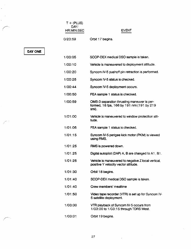
T + (PLUS)f-- DAY/
HR:MIN:SEC EVENT
0/23:59 Orbit 17 begins.
L J1/00:05 SCOP-DEX medical DSO sample is taken.
1/00:10 Vehicle is maneuvered to deployment attitude.
1/00:20 Syncom IV-5 pushoff pin retraction is performed.
1/00:25 Syncom IV-5 status is checked.
1/00:44 Syncom IV-5 deployment occurs.
1/00:50 FEA sample I status is checked.
1/00:59 OMS-3 separation thrusting maneuver is per-formed, 18 fps, 166 by 191 nmi (191 by 219smi).
1/01:00 Vehicle is maneuvered to window protection atti-tude.
fJ
1/01:05 FEA sample 1 status is checked.
1/01 :15 Syncom IV-5 perigee kick motor (PKM) is viewedusing RMS.
1/01:25 RMS is powered down.
1/01:25 Digital autopilot (DAP) A, B are changed to A1, B1.
1/01:25 Vehicle is maneuvered to negative Z local vertical,positive Y velocity vector attitude.
1/01:30 Orbit 18 begins.
1/01:40 SCOP-DEX medical DSO sample is taken.
1/01:40 Crew members' mealtime
1/01:50 Video tape recorder (VTR) is set up for Syncom IV-5 satellite deployment.
1/03:00 VTR playback of Syncom IV-5 occurs from1/03:00 to 1/03:15 through TDRS West.
S- 1/03:01 Orbit 19 begins.
27

T + (PLUS)DAY/
HR:MIN:SEC EVENT
1/03:55 SCOP-OEX medical 080 sample is taken.
1/04:05 MS-3 performs aerobics medical 0S0.
1/04:10 FEA sample 1 status is checked.
1/04:32 Orbit 20 begins.
1/04:50 FEA sample I status is checked.
1/05:05 Aerobics medical DSO is performed.
1/05:15 Vehicle is maneuvered to IMU alignment attitude.
1/05:30 Crew begin presleep activity.
1/05:35 IMU isalignedusingST.
1/05:40 Vehicle is maneuvered to negative Z local vertical,positive Y velocity vector attitude.
1/05:55 FEA sample 1 is terminated.
1/06:05 SCOP-DEX medical DSO sample is taken.
1/06:05 Pilot performs aerobics medical DSO.
1/06:03 Orbit 21 begins.
1/07:34 Orbit 22 begins.
1/08:30 Crew begins 8-hour sleep period.
1/09:05 Orbit 23 begins.
1/10:36 Orbit 24 begins.
1/12:07 Orbit 25 begins.
1/13:38 Orbit 26 begins.
1/15:09 Orbit 27 begins.
1/16:30 Crew ends 8-hour sleep period and beginspostsleep activity.
1/16:40 Allcrew members perform aerobics and pulse ratemedical DSO.
28

T + (PLUS)F- DAY/
HR:MIN:SEC EVENT
F_ZACTIVITIES
-- Food preparation, 30 minutes.
-- PCG fan inlet cleaning and temperature checks.
1/16:40 Orbit 28 begins.
1/18:00 SCOP-DEX medical DSO sample is taken.
1/18:11 Orbit29 begins.
1/18:45 01, COAS is tumed to OFE COAS is mountedforward.
1/18:45 Photo/'l'Vare set up for FEA.
1/18:50 FEA is reset.
1/18:50 Vehicleis maneuvered to IMU alignment attitude.
1/19:10 IMU is aligned using ST.
1/19:15 Vehicle is maneuvered to COAS calibration attitude.
1/19:15 Photo/TV are activated for FEA.
1/19:30 COAS is calibrated.
1/19:35 01, COAS is turned to OFF,COAS is stowed.
1/19:35 FEA is activated for sample 2.
1/19:42 Orbit 30 begins.
1/20:55 FEA sample 2 statusis checked.
1/21:13 Orbit 31 begins.
1/21:35 FEAsample 2 statusis checked.
1/21:55 AFE operationsare performed.
1/22:05 FEA sample2 statusis checked.
1/22:44 Orbit 32 begins.
1/23:40 MS-3 performsaerobics medicalDSO.f
/
29

T + (PLUS)DAY/
HR:MIN:SEC EVENT
1/23:55 FEA sample 2 status i8 checked.
I J2/00:15 Orbit 33 begins.
2/00:35 Vehicle is maneuvered to negative Z local vertical,positive Y velocity vector attitude.
2/01:00 Crew members' mealtime.
2/01:46 Orbit 34 begins.
2/02:03 Normal slow rate (NSR) maneuver occurs with anOMS single engine thrusting period, 41.8 fps, 166by 167 nmi (191 by 192 smi).
2/02:20 Photo/TV are set up for middeck activities.
2/02:50 FEA sample 2 status is checked.
2/02:50 Photo/TV are activated for middeck activitiesthrough TDRS West from 2/03:15 to 2/03:30.
2/03:05 AFE operations.
2/03:16 Orbit 35 begins.
2/03:52 NC-3 occurs with a single OMS engine thrustingperiod, 8 fps, 161 by 166 nmi (185 by 191 smi).
2/04:10 FEA sample 2 status ischecked.
2/04:20 Pilot performs aerobics medical DSO.
2/04:35 FEA sample 2 status is checked.
2/04:35 Photo/TV are set up for FEA.
2/04:47 Orbit 36 begins.
2/05:00 Crew begins presleep activity.
2/05:20 Commander performs aerobics medical DSO.
2/05:30 Vehicle is maneuvered to IMU alignment attitude.
2/05:40 FEA sample 2 is terminated.
2/05:45 IMU is aligned using ST.
3O

"I"+ {PLUS)DAY/
,"_" HR:MIN:SEC EVENT
2/05:45 Vehicle is maneuvered to negative Z local vertical,positive Y velocity vector attitude.
2/06:05 SCOP-DEX medical DSO sample is taken.
2/06:17 Orbit 37 begins.
2/06:20 Crew resets FEA.
2/07:48 Orbit 38 begins.
2/08:00 Crew begins 8-hour sleep period.
2/09:18 Orbit 39 begins.
2/10:48 Orbit 40 begins.
2/12:19 Orbit 41 begins.
2/13:49 Orbit 42 begins.
2/15:20 Orbit 43 begins.
2/16:00 Crew ends 8-hour sleep period and beginspostsleep activity.
EZ ACTIVITIES
-- Food preparation, 30 minutes.
-- PCG fan inlet cleaning and temperature checks.
2/16:10 All crew members perform aerobics and pulse ratemedical DSO.
2/16:50 Orbit 44 begins.
2/17:10 Photo/TV are activated for FEA.
2/17:10 FEA sample 3 is activated.
2/17:35 Vehicle is maneuvered to IMU alignment attitude.
2/17:55 IMU is aligned using ST.
2/17:55 Vehicle is maneuvered to negative Z local vertical,positive Y velocity vector attitude.
2/18:17 Commander configures aft flight station fors- rendezvous./
31

T + (PLUS)DAY/ --
HR:MIN:SEC EVENT
2/18:21 Orbit 45 begins.
2/18:24 Commander enables rendezvous navigation.
2/18:29 Commander configures DAP A, B to A9, B6.
2/18:35 AFE operations are performed.
2/18:35 FEA sample 3 status is checked.
2/18:58 Normal height adjustment (NH) maneuver is per-formed with a single OMS thrusting period, 21.2fps, 149 by 166 nmi (171 by 191 sm), range toLDEF is approximately 400,000 feet.
2/19:05 PEA sample 3 status is checked.
2/19:25 FEA sample 3 status is checked.
2/19:43 NC-4 maneuver is performed with a single OMSengine thrusting period 35.8 fps, 145 by 149 nmi(166 by 171 sm).
2/19:44 Commanderperforms initial target track; range toLDEF is approximately 243,000 feet.
2/19:48 Commander performs ST target acquisition.
2/19:51 Orbit 46 begins.
2/20:10 Photo/TV are set up for LDEF retrieval.
2/20:10 FEA sample 3 status is checked.
2/20:13 MS ends ST navigation.
2/20:49 When range to LDEF is less than approximately150,000 feet, pilot configures for rendezvousradar target acquisition.
2/21 :10 Photo/TV are activated for LDEF retrieval.
2/21:17 MS performs ST target acquisition.
2/21:21 Orbit 47 begins.
2/21:42 MS ends ST navigation.
32

T + (PLUS)DAY/
_ HR:MIN:SEC EVENT
2/21:43 MS-1 tums port RMS heater (2) to AUTO, panelA8L.
2/21:49 Commander performs normal corrective combina-tion (NCC) maneuver with an RCS thrusting period.
2/21:57 When rendezvous radar lock-on occurs, com-mander activates rendezvous radar navigationat arange of approximately 114,000 feet from !_DEE
2/22:30 FEA sample 3 is terminated.
2/22:43 Terminalphase initiation (TPI) occurs, commanderperforms RCS thrusting period, 3.2 fps, 147 by149 nmi (169 by 171 smi); range to LDEF isapproximately 49,000 feet.
2/22:48 MS performs RMS power up.
2/22:51 Orbit 48 begins.
2/22:57 MS performs RMS maneuver to poise position forLDEF capture.
I
2/23:08 Commander performs midocurse correction(MC)-I maneuver using RCS, range to LDEF isapproximately 50,000 feet.
2/23:34 Commander performs MC-2 using RCS, approxi-mately 31,000 feet from I_DEE
2/23:44 Commander performs MC-3 using RCS, approxi-mately 23,000 feet from I..DEE
2/23:46 Commander configures CCTM.
2/23:55 Commander performs MC-4 using RCS, approxi-mately 4,500 feet from LDEE
2/23:56 Manual trajectory control occurs.
2/23:58 MS notes LDEF orientation when approximately3,500 feet from I_DEE
DAYTHREEJ3/00:00 Vehicle crosses radius (R)-bar; commander config-
ures for velocity (V)-barf- .
//
33

T + (PLUS)DAY/ ---
HR:MIN:SEC EVENT
3/00:16 Proximity operations are performed.
3/00:17 Commander turns Ku-radar output to LO, panelA1U.
3/00:19 Commander notes LDEF orientation.
3/00:20 Orbit 49 begins.
3/00:21 Vehicle crosses V-bar.
3/00:26 Commander configures for R-bar approach.
3/00:44 Commander establishes R-bar.
3/00:46 MS-1 notes LDEF orientation.
3/00:47 Commander performs vehicle alignment.
3/00:48 Commander initiates closing rate using RCS.
3/00:49 MS-1 turns payload bay flood docking to bright;panelA7U.
3/01:12 Commander configures Ku-band for communica-tion mode.
3/01:17 MS-1 performs LDEF capture.
3/01:21 MS-1 sets RMS brakes to ON.
3/01:24 Commander disables rendezvous navigation.
3/01:45 Vehicle i8maneuvered to survey attitude, positive Ylocal vertical, positive Z velocity vector attitude.
3/01:50 Orbit 50 begins.
3/02:05 When vehicle is maneuvered to survey attitude,LDEF photo survey is performed.
3/03:05 Photo/TV are activated for LDEF retrieval.
3/03:20 Orbit 51 begins.
3/04:25 The LDEF is berthed in Columbia's payload bay.
3/04:50 Orbit 52 begins.
34

T + (PLUS),,i-- DAY/
HR:MIN:SEC EVENT
3/05:00 The LDEF experiment initiation system (EIS) isdeactivated.
3/05:10 Vehicle is maneuvered to bias plus Y local vertical,plus Z velocity vector attitude
3/05:15 RMS is powered down.
3/05:15 Star table is cleared.
3/05:25 Crew begins presleep activity.
3/05:41 IMU is aligned using ST.
3/05:45 Vehicle is maneuvered to negative X solar inertialattitude.
3/06:00 Vehicle is maneuvered to negative X solar inertialorbit rotation rate.
3/06:20 Orbit 53 begins.
_- 3/07:45 Vehicleis maneuvered to negative Z local vertical,negative Y velocity vectorattitude.
3/07:50 Orbit 54 begins.
3/08:00 Crew begins8-hour sleep period.
3/09:20 Orbit55 begins.
3/10:50 Orbit 56 begins.
3/12:19 Orbit 57 begins.
3/13:49 Orbit 58 begins.
3/15:19 Orbit 59 begins.
3/16:00 Crew ends 8-hour sleep period and beginspostsleepactivity.
EZ ACTIVITIES
-- Food preparation,30 minutes.
-- PCG fan inletcleaningand temperaturecheck.
.._ 3/16:10 All crew members perform aerobics and pulse rate,' medical DSO.
35

T + (PLUS) _--DAY/
HR:MIN:SEC EVENT
3/16:35 SCOP-DEX medical DSO dosage is taken.
3/16:49 Orbit 60 begins.
3/17:05 ECLSS supply water dump from the flash evapora-tor system (FES) occurs.
3/17:05 SCOP-DEX medical DSQ sample i8 taken.
3/17:35 SCOP-DEX medical DSO sample is taken.
3/17:55 Vehicle ismaneuvered to bias negative Z local verti-cal, negative Y velocity vector attitude.
3/17:55 Star table is cleared.
3/18:19 Orbit 61 begins.
3/18:23 IMU is aligned using ST.
3/18:30 Vehicle is maneuvered to negative Z local vertical,negative Y velocity vector attitude.
3/18:35 A.FEoperationsare performed.
3/18:35 SCOP-DEX medicalDSO sampleis taken.
3/19:05 Latitude/longitudeIocator(L3) isset up.
3/19:40 VTR is set up for LDEF retrieval.
3/19:45 L3 state vector (SV) updateoccurs.
3/19:49 Orbit 62 begins.
3/19:55 Photo/TVare set up for crew conference.
3/20:00 V'rR playbackof LDEFretrieval occurs throughTDRS West from3/20:00 to 3/20:20.
3/20:25 L3 observationof IslaGuv occurs.
3/20:25 Photo/TVare activatedfor crew conferencethroughTDRS East, 3/20:48 to 3/21:05.
3/20:35 SCOP-DEX medical DSO sample istaken.
36

T + (PLUS)DAY/
HR:MIN:SEC EVENT
3/20:48 Crew conference with all crew members occurs.
3/21:19 Orbit 63 begins.
3/21:50 MS-3 performs aerobics medical DSO.
3/21:50 Crew resets FEA.
3/22:00 L3 observation of Monterre and KSC occurs.
3/22:30 SCOP-DEX medical DSO sample is taken.
3/22:30 Photo/TV is set up for FEA.
3/22:49 Orbit 64 begins.
3/23:00 Crew members' mealtime.
[ DAYFOUR I4/00:15 L3 SV updateoccurs.
"_ 4/00:15 Photo/TV are activated for FEA.
4/00:18 Orbit 65 begins.
4/00:35 SCOP-DEX medical DSO sample is taken.
4/00:35 FEA sample 4 is activated.
4/00:55 L3 observation of Lanai Island occurs.
4/01:05 L3 observation of Cedros Islandoccurs.
4/01:20 L3 observation of SanJuan occurs.
4/01:35 AFE operations are performed.
4/01:48 Orbit 66 begins.
4/02:05 ECLSS supply dump from the FES occurs.
4/02:05 FEA sample 5 status is checked.
4/02:30 SCOP-DEX medical DSO sample is taken.
4/02:35 Commander performs aerobics medical DSO.
ff
37

T + (PLUS)DAY/
HR:MIN:SEC EVENT
4/02:35 FEA sample 5 status is checked.
4/02:50 L3 observation of La Gune occurs.
4/03:05 FEA sample 5 status is checked.
4/03:18 Orbit 67 begins.
4/03:40 FEA sample 5 is terminated.
4/03:50 Pilot performs aerobics medical DSO.
4/04:00 Crew begins presleep activity.
4/04:35 Star table is cleared.
4/04:45 SCOP-DEX medical DSO sample is taken.
4/04:48 Orbit 68 begins.
4/05:02 IMU is aligned using ST,
4/06:18 Orbit 69 begins.
4/07:00 Crew begins 8-hour sleep period.
4/07:48 Orbit 70 begins.
4/09:18 Orbit 71 begins.
4/10:47 Orbit 72 begins.
4/12:17 Orbit 73 begins.
4/13:47 Orbit 74 begins.
4/15:00 Crew ends 8-hour sleep pedod, and beginspostsleep activity.
EZ ACTIVITIES
-- Food preparation, 30 minutes.
-- PCG fan inlet cleaning and temperature check.
4/15:10 All crew members perform aerobics and pulse ratemedical DSO.
4/15:17 Orbit 75 begins.
38

T + (PLUS)DAY/
HR:MIN:SEC EVENT
4/16:30 SCOP-DEX medical DSO sample is taken.
4/16:45 Star table is cleared.
4/16:47 Orbit 76 begins.
4/17:00 RCS regulator is reconfigured, 07/08, helium pres-sure A (3) to CLOSED; B(3) to GPC, OPEN.
4/17:12 IMU is aligned using ST.
4/17:25 Cabin temperature controller is reconfigured,MD44F, pin cabin temperature controller actuatorlinkage to actuator 2, L1, cabin temperature con-troller 2
4/17:50 Humidity separator is reconfigured, L1, humiditySEP B to OFF,A to ON.
4/17:55 Manual fuel cell purge is performed.
4/18:00 AFE operationsare performed.
r-. 4/18:05 Crew resets FEA.
4/18:05 Heater is reconfigured to B.
4/18:15 Pressure control system isconfigured to 1.
4/18:17 Orbit 77 begins.
4/18:25 ECLSS redundant component checkout isperformed.
4/18:55 L3 SV updateoccurs.
4/19:05 AFE operationsare performed.
4/19:05 Photo/TVare set up for FEA.
4/19:05 PEA sample4 isactivated.
4/19:10 L3 observationof IslaJuv occurs.
4/19:25 L3 observationof Tenerifeoccurs.
4/19:35 Photo/TVare activatedfor FEA.
4/19:47 Orbit 78 begins.f
39

T + (PLUS)DAY/ ....
HR:MIN:SEC EVENT
4/20:50 L3 observation of Lake Oke occurs.
4/21:05 L3 observation of Presqui occurs,
4/21:1 5 Filter cleaning and scheduled inflight maJntenaceoccur.
4/21:16 Orbit 79 begins.
4/22:00 Crew members' mealtime.
4/22:46 Orbit 80 begins.
4/23:05 L3 SV update occum.
4/23:45 L3 observation of Mauna Lo occurs.
4/23:55 L3 observationof Cedros Islandoccurs.
[ DAYFIVE I5/00:10 FEA sample4 is terminated.
5/00:16 Orbit 81 begins.
5/00:35 AFE operationsare performed.
5/01:20 L3 observation of Niihauoccurs.
5/01:20 Commanderperforms aerobicsmedicalDSO.
5101:40 L3 observation of Kingstonoccurs.
5/01:45 Photo/TVare set up for middeckactivities.
5/01:46 Orbit 82 begins.
5/02:15 Photo/'rv are activated for middeckactivitiesthrough"I'DRSWest from 5t03:40 to 5/03:22.
5/02:20 Crew resets FEA.
5/02:35 Pilotperforms aerobics medicalDSO.
5/02:50 L3 observation of Midway occurs.
5/03:00 Crew begins10resleepactivity.
5/03:15 Vehicleis maneuveredto biasnegativeZ localverti-cal negativeY velocityvector attitude.
40

T + (PLUS)_- DAY/
HR:MIN:SEC EVENT
5/03:16 Orbit 83 begins.
5/03:25 Star table is cleared.
5/03:51 IMU is aligned using ST.
5/04:00 Vehicle is maneuvered to negative Z local vertical,negative Y velocity vector attitude.
5/04:35 SCOP-DEX medical DSO sample is taken.
5/04:46 Orbit 84 begins.
5/06:00 Crew begins 8-hour sleep period.
5/06:16 Orbit 85 begins.
5/07:45 Orbit 86 begins.
5/09:15 Orbit 87 begins.
5/10:45 Orbit 88 begins./
5/12:15 Orbit 89 begins.
5/13:45 Orbit 90 begins.
5/14:00 Crew ends 8-hour sleep period and beginspostsleep activity.
EZ ACTIVITIES
-- Food preparation,30 minutes.
-- PCG fan inletcleaningandtemperature check.
5/14:10 Allcrew membersperformaerobicsand pulse ratemedicalDSO.
5/15:15 Orbit91 begins.
5/15:37 Vehicleis maneuveredto bias negativeZ localverti-cal, negativeY velocity vectorattitude.
5/15:37 Star table is cleared.
5/15:45 Photo/TV are set up for middeck activities.
f-- 5/16:09 IMU isaligned using ST./
41

T + (PLUS)DAY/ .....
HR:MIN:SEC EVENT
5/16:15 Photo/TV are activated for middeck activitiesthrough TDRS West from 5/17:30 to 5/18:00.
5/16:15 Vehicle is maneuvered to negative Z local vertical,negative Y velocity vector attitude.
5/16:35 MS-1 performs lower body negative pressure(LBNP) medical DSO.
5/16:45 Orbit 92 begins.
5/17:15 1.3SV update occurs.
5/17:55 MS-3 performsLBNP medicalDSO.
5/17:55 L3 observationof Cosiguinoccurs.
5/18:10 L3 observationof Tenedfe occurs.
5/18:14 Orbit 93 begins.
5/18:25 L3 observationof LTanaoccurs.
5/18:45 Crew resets FEA.
5/18:50 Photo/IV are set up for CNCR.
5/19:20 Photo/TVare activatedfor CNCR.
5/19:30 L3 observationof Mexico City occurs.
5/19:40 CNCR remarksare made.
5/19:44 Orbit 94 begins.
5/19:55 L3 observationof Chad Ri occurs.
5/20:10 Crew members' mealtime.
5/21:45 MS-1 performs IRNP medical DSO.
5/22:00 1_3SV update occurs.
5/22:35 MS-3 performs U3NPmedical DSO.
5/22:45 Orbit 98 begins.
5/22:45 L3 observation of Galveston Bay
5/23:35 AFE operations are performed.
42

T + (PLUS)
../--.. DAY/HR:MIN:SEC EVENT
[ D,_S,X ]6/00:05 L3 observation of Niihau occurs.
6/00:14 Orbit 97 begins.
6/00:20 . Commander performs aerobics medical DSO.
6/00:25 L3 observation of I_agoEng occurs.
6/00:45 PhotoFrV are set up for FEA.
6/01:05 Commander performs aerobics medical DSO.
6/01:20 Photo/TV are activated for FEA.
6/01:35 Pilot performs aerobics medical DSO.
6/01:35 FEAsample 6 isactivated.
6/01:44 Orbit 98 begins.
_ 6/01:50 L3 observation of Lagunaoccurs.
6/02:17 Vehicleis maneuveredto biasnegativeZ localverti-cal, negative Y velocity vectorattitude.
6/02:17 Star tableis cleared.
6/02:30 Crew beginspresleepactivity.
6/02:48 IMU is alignedusingST.
6/02:50 Vehicleis maneuvered to negativeZ localvertical,negative Y velocityvector attitude.
6/03:13 Orbit 99 begins.
6/03:,35 FEA sample6 is terminated.
6/04:43 Orbit1O0 begins.
6/05:30 Crew begins8-hoursleep pedod.
6/06:13 Orbit 101 begins.
6/07:43 Orbit 102 begins.
43
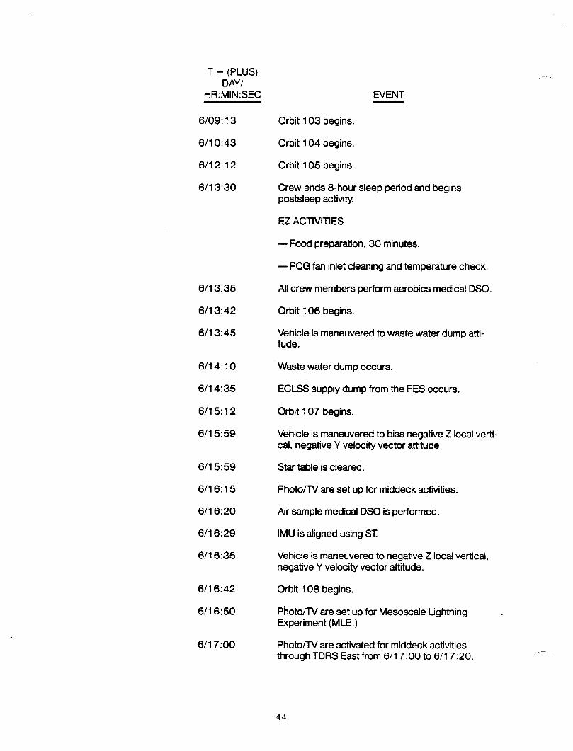
T + (PLUS) -DAY/
HR:MIN:SEC EVENT
6/09:13 Orbit 103 begins.
6/10:43 Orbit 104 begins.
6/12:12 Orbit 105 begins.
6/13:30 Crew ends 8-hour sleep period and beginspostsleep activity.
F_.ZACTIVITIES
Food preparation, 30 minutes.
-- PCG fan inlet cleaning and temperature check.
6/13:35 All crew members perform aerobics medical DSO.
6/13:42 Orbit 106 begins.
6/13:45 Vehicle is maneuvered to waste water dump atti-tude.
6/1 4:10 Waste water dumpoccurs.
6/14:35 ECLSS supplydump from the FES occurs.
6/15:12 Orbit 107 begins.
6/15:59 Vehicle is maneuveredto bias negativeZ localverti-cal, negativeY velocity vectorattitude.
6/15:59 Star table is cleared.
6/16:15 Photo/TV are set up for middeck activities.
6/16:20 Airsamplemedical DSO is performed.
6/16:29 IMU isaligned using ST.
6/16:35 Vehicle is maneuvered to negative7 local vertical,negativeY velocityvector attitude.
6/16:42 Orbit 108 begins.
6/16:50 Photo/TVare set upfor Mesoscale LightningExperiment(MLE.)
6/17:00 Photo/TV are activated for middeck activities .through TDRS East from 6/17:00 to 6/17:20.
44

..__. T + (PLUS)DAY/
HR:MIN:SEC EVENT
6/17:05 MS-1 performs IRNP medical DSO.
6/17:10 L3 SV update occurs.
6/17:20 Photo/TV are activated for MLE.
6/18:12 Orbit 109 begins.
6/18:15 L3 observation of Laguna occurs.
6/18:35 L3 observationof Canary Islandoccurs.
6/18:55 Crew resets FEA.
6/19:05 ECLSS supply dump from the FES occurs.
6/19:10 Photo/'TV are activated for MLE.
6/19:42 Orbit 110 begins.
6/19:55 L3 observation of KSC occurs.
/ - 6/20:15 L3 observationof L. Faguib occurs.
6/20:35 Photo/TVare set up for FEA.
6/20:40 Photo/TVare activatedfor MLE.
6/21:00 Crew members' mealtime.
6/21:11 Orbit 111 begins.
6/22:05 FEA sample7 isactivated.
6/22:05 Photo/TV are activatedfor FEA.
6/22:10 L3 SV updateoccurs.
6/22:10 Photo/TVare activatedfor MLE.
6/22:41 Orbit 112 begins.
6/22:50 L3 observation of Lanaioccurs.
6/23:10 L3 observationof LakeOke occurs.
6/23:35 AFE operations are performed.
F- 6/23:35 FEA sample 7 status is checked.
45

T + (PLUS) .....DAY/
HR:MIN:SEC EVENT
DAYSEVEN 17/00:05 FEA sample 7 status is checked.
7/00:11 Orbit 113 begins.
7/00:20 Commanderperformsaerobics medical DSO.
7/00:35 FEA sample 7 statusischecked.
7/00:50 L3 observationof Essequiboccurs.
7/01:35 Pilotperforms aerobics medical DSO.
7/01:41 Orbit 114 begins.
7/01:55 L3 observationof Midway occurs.
7/02:00 Crew begins presleep activity.
7/02:05 PilotperformsaerobicsmedicalDSO.
7/02:05 FEA sample 7 statusischecked.
7/02:39 Vehicle ismaneuvered to biasnegative Z localverti-cal, negativeY velocityvectorattitude.
7/02:40 Star table is cleared.
7/03:08 IMU is alignedusingST.
7/03:11 Orbit 115 begins.
7/03:15 Vehicleis maneuveredto negativeZ localvertical,negative Y velocityvector attitude.
7/03:35 FEA sample 7 isterminated.
7/04:41 Orbit 116 begins.
7/05:00 Crew begins8-hour sleep period.
7/06:10 Orbit 117 begins.
7/07:40 Orbit 118 begins.
7/09:10 Orbit119 begins.
46

T + (PLUS)._-- DAY/
HR:MIN:SEC EVENT
7/10:40 Orbit 120 begins.
7/12:10 Orbit 121 begins.
7/13:00 Crew ends 8-hour sleep period and beginspostsleep activity.
E..ZACTIVITIES
-- Food preparation, 30 minutes.
-- PCG fan inlet cleaning and temperature check.
7/13:10 All crew members perform aerobics medical DSO.
7/13:40 Orbit 122 begins.
7/14:45 1.3SV update occurs.
7/14:50 Star table iscleared.
7/15:09 Orbit 123 begins.
.... 7/15:18 IMU is alignedusingST.
7/16:00 L3 observationof Socotraoccurs.
7/15:10 Crew resets FEA.
7/16:15 MS-1 performsLBNP medicalDSO.
7/16:39 Orbit 124 begins.
7/16:50 Crew stowsFEA.
7/17:05 MS-3 pe#orms LBNP medical DSO. '
7/17:30 L3 observation of Emi Kous occurs.
7/17:30 Photo/TV are set up for middeck activity.
7/18:00 Photo/TV are activated for middeck activitiesthrough TDRS West from 7/18:1 5 to 7/18:45.
7/18:09 Orbit 125 begins.
7/19:00 L3 observation of Richat occurs.
f_ 7/1 9:10 L3 observation of Kilimanjoccurs.
47

T + (PLUS) .DAY/
HR:MIN:SEC EVENT
7/19:39 Orbit 126 begit
7/20:15 L3 observatior ,_iRiver occurs.
7/20:35 L3 observation_,..,,,akarand Lac Tomeoccurs.
7/21:00 Crew members' mealtime.
7/21:09 Orbit 127 begins.
7/22:25 1_3SV update occurs.
7/22:39 Orbit 128 begins.
7/22:50 All crew members perform skin test medical DSO.
7/23:50 AFE operations are performed.
[ DAY EIGHT I8/00:08 Orbit 129 begins.
8/00:40 Commander performs aerobics medical DSO.
8/01:05 L3 observation of Lake Nic occurs.
8/01:30 Star table iscleared.
8/01:38 Orbit 130 begins.
8/01:50 Pilot performs aerobics medicaJDSO.
8/01:57 IMU is alignedusing ST.
8/02:00 Crew begins presleep activity.
8/03:08 Orbit 131 begins.
8/04:38 Orbit 132 begins.
8/05:00 Crew begins8-hour sleep period.
8/06:08 Orbit 133 begins.
8/07:37 Orbit 134 begins.
8/09:07 Orbit 135 begins.
8/10:37 Orbit 136 begins.
48

f__ T + (PLUS)DAY/HR:MIN:SEC EVENT
8/12:07 Orbit 137 begins.
8/13:00 Crew ends 8-hour sleep period and beginspostsleep activity
EZ ACTIVITIES
-- Food preparation,30 minutes.
o PCG fan inletcleaningand temperaturecheck.
8/13:10 Allcrew members performaerobicsmedical DSO.
8/13:37 Orbit 138 begins.
8/15:07 Orbit 139 begins.
8/15:12 Vehicleis maneuveredto biasnegativeZ localverti-cal, negative Y velocityvectorattitude.
8/15:12 Star table is cleared.
z--- 8/15:20 APU steamvent heater is activated; boilercontroller/heater(3) is turned to B; power (3) toON.
8/15:38 IMU isalignedusingST.
8/15:45 Vehicleismaneuvered to negativeZ localvertical,positiveY velocityvectorattitude.
8/16; 15 Rightcontrolsystem checkoutis performed.
8/16;36 Orbit140 begins.
8/17:05 M8-3 performs LBNP medicalDSO.
8/17:36 RCS hot fire testoccurs.
8/17:50 Crew configuresDAPto AI/AUTO/VERNIER.
8/17:50 AFE operationsare performed.
8/18:00 Orbit 141 begins.
8/18:15 APU fuel pump/valvecool A is turned to OFF
8/18:30 APU heater isreconfigured.
I
49

T + (PLUS)DAY/
HR:MIN:SEC EVENT
8/18:50 L3 SV update occurs.
8/19:05 Commander performs aerobics medical DSO.
8/19:20 L3 observation of Presqui and Cameroon occurs,
8/19:36 Orbit 142 begins.
8/20:10 Crew members' mealtime.
8/21:06 Orbit 143 begins.
8/21 :15 Photo/'rv are set up for PCG.
8/21:15 Crew stows LBNP medicalDSO.
8/21:20 L3 SV updateoccurs.
8/21:45 Photo/TVare activated for PCG throughTDRSWest from 8/22:03 to 8/22:27.
8/21:47 Orbit142 begins.
8/22:05 L3 observationof San Juan occurs.
8/22:05 Pilot performs aerobics medical DSO.
8/22:05 PCG is deactivated.
8/22:36 Orbit 144 begins,
8/23:00 All crew members perform cabin configuration andstowage.
L J9/00:05 Orbit 145 begins.
9/01:51 Vehicle is maneuvered to bias negative Z local verti-cal, negative Y velocity vector attitude.
9/01:35 Orbit 146 begins.
9/01:51 Star table is cleared.
9/02:00 Crew begins presleep activity.
9/02:17 IMU is aligned using ST.
5o

T + (PLUS)DAY/
f- HR:MIN:SEC EVENT
9/02:25 Vehicle is maneuvered to negative Z local vertical,negative Y velocity vector attitude.
9/03:05 Orbit 147 begins.
9/04:35 Orbit 148 begins.
9/05:00 Crew begins 8-hour sleep period.
9/06:05 Orbit 149 begins.
9/07:34 Orbit 150 begins.
9/09:04 Orbit 151 begins.
9/10:34 Orbit 152 begins.
9/12:04 Orbit 153 begins.
9/13:00 Crew ends 8-hour sleep period and beginspost_leep activity.
9/13:10 All crew members perform aerobics medical DSO.
9/13:34 Orbit 154 begins.
9/14:01 Maneuver vehicle ismaneuvered to bias negative Zlocal vertical, negative Y velocity vector attitude.
9/14:01 Star table is cleared.
9/14:30 IMU isaligned using ST.
9/14:35 Vehicle is maneuvered to negative X solar inertialattitude.
9/14:50 PCG is deactivated.
9/14:50 Vehicle rotation is maneuvered.
9/15:03 Orbit 155 begins.
9/15:20 Cabin air monitoring DTO is performed.
9/15:20 Two crewmen perform lOP medical DSO.
9/15:35 Characterization of airborne particulate matter inshuttle atmosphere is performed.
51

T + (PLUS)DAY/ r-
HR:MIN:SEC EVENT
EZ ACTIVITIES
-- Air sample.
--Fluid loading preparation, fill 4 drinkcontainerswith 8 ounces of H20 each (per person).
9/16:01 Cathode-ray tube (CRT) timer is set up.
9/16:06 Coldsoak attitude is initiated.
9/16:16 Crew stows radiators, if required.
9/16:33 Orbit 156 begins.
9/16:33 Crew configures data processing system (DPS)fordeorbit preparation.
9/16:36 MCC updates IMU pad, if required.
9/16:46 Crew configures for payload bay door closure.
9/16:56 Crew stows Ku-band antenna, if required.
9/17:02 Vehicle is maneuvered to IMU alignmentattitude.
9/17:09 DAP is set to B/AUTO/NORMAL
9/17:10 Radiator is set to BYPASSand FES is checked out.
9/17:12 MCC issues "go for payload bay door closure"command.
9/17:16 IMU is aligned with ST
9/17:21 Payload bay doors are closed.
9/17:31 Preliminary deorbit udpate/uplink occurs.
9/17:40 Crew configures dedicated displays.
9/17:44 MCC issues "go for OPS 3" command.
9/17:47 Vehicle is maneuvered to deorbit burn attitude.
9/17:56 Crew configures DPS for entry.
9/18:03 Orbit 157 begins.
52

T + (PLUS)DAY/
(/'-'" HR:MIN:SEC EVENT
9/18:06 All crew members vedfy entry switch list.
9/18:21 All crew members perform entry review.
9/18:36 Commander and pilot don LES clothing.
9/18:51 MSs don LES clothing.
9/19:01 Commander and pilot ingress seats.
9/19:33 Orbit 158 begins.
9/19:47 Deorbitupdate isperformed.
9/19:49 Right crew performs OMS gimbalcheck.
9/20:12 MCC issues "go for decrbit thrustingmaneuver"command.
9/20:19 Crew maneuversvehicleto qleorbitignitionattitude.
9/20:21 Crew terminatesvehicleto deorbitignitionattitude,
f-"_ 9/20:21 MSs ingressseats.f
9/20:29 First APU isactivated.
9/20:34:52 Deorbit thrusting maneuver isperformed, 4 min-utes, 34 seconds in duration, 259 fps.
9/20:40 Crew proceeds to major mode (MM) 303.
9/20:41 Crew maneuvers vehicle to post deorbit thrustingattitude.
9/20:43 Forward RCS dump is performed if required.
9/20:45 Crew terminates vehicle post deorbit thrustingattitude.
9/20:51 Crew starts two remaining APUs.
9/20:53 SSME hydraulic systems are repressurized.
9/20:59 MM 304 is selected.
9/21:03 Orbit 159 begins.
9/21:04:50 Vehicle achieves entry interface (El), 400,000 feet/--_ altitude.
53

GLOSSARY
AA accelerometer assemblyADSF automatic directional solidification furnaceAES atmosphere exchange systemNL approach and landingAMOS Air Force Maui optical siteAMU attitude match updateAOA abort once aroundAPU auxiliary power unitARC Aggregation of Red Blood Cells ExperimentARS attitude reference systemASE airborne support equipment
CAP crew activity planCAPS crew altitude protection suitCBSA cargo bay stowage assemblyCCTV closed-circuittelevisionCEC controlelectronics containerCFES continuousflow electrophoresissystemCIU communicationsinterfaceunitCOAS crewmanopticalalignmentsightCRT cathode-ray tubeCSS control stick steering
DEX dextrcsmphetamine( DMOS diffusivemixingof organicsolutions
DPS data processingsystemDSO detailedsupplementaryobjectiveDTO detailedtest objective
EAFB EdwardsAir Force BaseEAC experimentapparatus containerECLSS environmentalcontroland lifesupport systemEEP electronics equipment packageELRAD Earth LimbRadianceExperimentEMU extravehicularmobilityunitEPS electricalpower systemET extemal tankEV extravehicularEVA extravehicularactivity
FC fuel cellFES flashevaporatorsystemfps feet per secondFSS flightsupport structureFSS flightsupportsystem
GAS getaway specialGEM generic electronics moduleGHCD Growth HormoneConcentrationand DistributionGLS ground launc_sequencer
/_ GPC general-purpose computerI GSFC Goddard Space Flight Center
57

HDRS high data rate system ---HGAS high-gain antenna systemHRM hand-held radiation meterHUD head-up display
IEF isoelectric Focusing ExperimentIMU inertial measurement unitIRCFE Infrared Communications Flight ExperimentlUS inertial upper stageIV intravehicular
JEA joint endeavor agreementJSC Johnson Space Center
kbps kilobitsper second
KSC Kennedy Space Center
LDEF long-durationexposure facilityLEASAT leased communi_b_n .satelliteLES launchentry suitLPS launchprocessingsystemLRU line replaceableunit
MC midcoursecorrection maneuverMCC-H -MiS_..'onCon_oi Center,HoustonMDM multiplexer/clE_multiplexer'MEB mainelectronicsbox , -MECO main engine cutoffMEM middeck electronics moduleMET missionelapsed time,_:,;iMFR manipulator foot restraintMILA Merritt Island " 'MLE Mesoscsle Ughtning ExperimentMLR monodisperselatexreactorMM majormodeMMU mannedmaneuveringunit
MPESS miasion-/::)_:;UJ_equipmentsupportstructureMFS mainpropuN0r_'systemMS missionspecialist
MSFC MarshallSpace Right Center
NC normalcorrective maneuverNCC normalcorrective combinationmaneuverNH normalheightadjustmaneuvernmi nauticalmileNPC normalplane change maneuverNSR normalslowrate maneuver
O&C operations and checkoutOCP Office of Commercial ProgramsOASIS Orbiter Experiment Autonomous Supporting Instrumentation
SystemOEX orbiter experiment ----OAST Office of Aeronautics and Space TechnologyOMS orbital maneuvering system
5_

. OSSA Office of Space Sciences and Applications. OSTA Office of Space and Terrestrial Applications
PALAPA Indonesian communication satellitePAM payload assist modulePCM payload control panelPCS pressure control systemPCG protein crystal growthPDI payload data intedeaverPFR portable foot restraintPGC plant growth chamberPGU plant growth unitPI payload interrogatorPIC pyro initiator controllerPL payload ::PM polymer morphology _-__._,POCC Payload Operations Control CenterPPE Phase Partitioning Experiment ........PRCS primary reaction controt._y_tem _ : _--PRM pocket radiation meter _. -PS payload specialist : .PT1 preprogrammedtest inputPVTOS PhysicalVapor TransportOrganicSolids Experiment
RAHF-VT research animal holdingfacility_vedficationtest 'RCC reinforced carbon-carton
_ RCS reactioncontrolsystem •/ =
RGA rategyroassembly ..... :' .........RME radiationmonitoringequipmettt -- _ 'RMS remotemanipulatorsystem ...RTGS radioisotopethermoelectricgenerators ;....RTLS returnto launchsite
S&A safe and armSAS space adaption syndromeSCOP scopolamine :.,SESA specialequipment stowage,assemblySHARE Space Station Heat PipeBadlator Element ExperimentSL Spsoelabsm statute mileSMS space motion sicknessSRB solid rocket booster .. _ " "SRSS shuttle range safety systemSSBUV Shutter Solar Backscatter Ultraviolet "SSIP shuttlestudent involvementprojectSSME space shuttlemainengine ' •ST startrackerSTEX SensorTechnologyExperimentSTS space transportationsystemSYNCOM synchronouscommunicationsatellite
TACAN tacticalairnavigationf"_._ TAEM terminalarea energy management
TAGS text and graphics systemTAL transatlantic landing
59

TDRS Tracking and Data Relay SatelliteTDRSS Tracking and Data Relay Satellite systemTI thermal phase initiationTIG time of_ignitionTLD therrnblumineacent dosimeterTPAD trunnion pin acquisition deviceTPF terminal phase final maneuver
• TPI terminal phase initiation maneuverTPS thermal protection system"IV television
•VCGS vapor crystalgrowthsystemVRCS vernier reactioncontrolsystem•VTR video rage recorder
VWFC very',Widefield_era
WCS ,W._as_tecO!!.e_tionsystem%
/
PUB 3546-W qEV 12-89
6O