offshore wind turbines integration improvement in …...offshore wind turbines integration...
TRANSCRIPT

Offshore Wind Turbines Integration improvement in the electric
network: A case study of the Tunisian electricity distribution network
(ASHTART)
Raida SELLAMI
Department of Electrical Engineering
University of Sfax ENIS, Tunisia
Rafik NEJI
Department of Electrical Engineering
University of Sfax ENIS, Tunisia
Tarek BOUKTIR
Department of Electrical Engineering
University Farhat Abbes Sétif1,Algeria
[email protected] [email protected] [email protected]
Abstract— During the past few years, the installed world
wind power capacity has increased massively. The
wind turbine should be integrated efficiently in electrical
network because of their uncertain and difficult prediction
of production. Offshore Wind turbines are often located in
far-off regions where grid access is relatively weak.
This paper focuses on the study of the electric networks
stability in presence of offshore wind turbines. The
application of simulations shows that after the addition of a
FACTS (Flexible Alternating Current Transmission
Systems) device such as STATCOM, the level of
penetration of wind energy without losing the stability of
the network has been significantly improved, as well as
maintaining stability increases even when a fault occurs.
Simulations were achieved on the Tunisian electricity
distribution network (ASHTART) of the SEREPT (Society
for Research and Exploitation of Petroleum) using the
Matlab-based toolbox (PSAT).
Index Terms— stability, offshore wind energy integration,
STATCOM, ASHTART.
1. INTRODUCTION
The man has a big profit of the strength of the wind
which appears from the antiquity with the use of windmills.
It is today that the wind energy became the greatest form of
renewable energy thanks to the Herculean strength which
produces the wind. It is also the least expensive clean
energy to produce, which explains the strong enthusiasm
for this technology. Such penetration of wind energy in
electricity consumption, raises many questions as to its
perfect fit with the technical constraints of the electrical
system in particular regarding the quality of electricity and
security of electrical energy systems which are relatively
delicate seen that they are often subject to disturbances may
lead in the majority of cases to damage to the conditions of
normal functioning, they also cause the loss of stability of
the entire system, the imbalance between production and
consumption and the discontinuity of service.
In this paper, we are going to be interested in the analysis
of the static and transient stability of the networks of
electrical energy further to disturbances:
· Variation of overload affecting the system,
· Application of defect (three phase symmetrical fault),
· Integrating a source of wind by using a DFIG wind
turbine (Doubly-fed induction generator).
The structure of this paper is as follows. First, the wind
turbine concepts are mentioned, also the static synchronous
compensator is described briefly. Then, the test system and
the result of all simulations are presented.
2. TURBINE MODELS
There are many different types of wind turbines in use
around the world, each having its own list of benefits and
drawbacks [1].
In recent years, the majority of wind farms that
connected to the grid are equipped with DFIG. This kind of
wind turbines is the most popular technology among
several wind turbines technologies because of their
numerous advantages over other types of generators when
used in wind turbines as that they allow the amplitude and
frequency of their output voltages to be maintained at a
constant value, no matter the speed of the wind blowing on
the wind turbine rotor, so DFIG can be directly connected
to the ac power network and remain synchronized at all
times with the ac power network, also the ability to control
the power factor while keeping the power electronics
devices in the wind turbine at a moderate size [2]-[3].
In this paper we will focus on a variable-speed wind
turbine with a doubly-fed-induction generator (DFIG) and
Fig. 1, shows the basic structure of this turbine.
The DFIG consists of a wound rotor induction generator
and back to back converter connecting the rotor slip rings
to the grid. The wind turbine is connected to the induction
generator through a mechanical shaft system. A gearbox is
linking high and low speed shafts in the shaft system. The
induction generator stator is directly connected to the grid
whereas the rotor is fed through a back to back voltage
source converter [4].
Also, the active and reactive power output of the DFIG
can be fully controlled by rotor side converter. The rating
of rotor side converter and grid side converter of DFIG are
about (25- 30%) of the total wind power [5].
Fig. 1. Doubly-fed induction generator.
Proceedings of the International Conference on Recent Advances in Electrical Systems, Tunisia, 2016
ISBN: 978-9938-14-953-1 (136) Editors: Tarek Bouktir & Rafik Neji
3. STATCOM
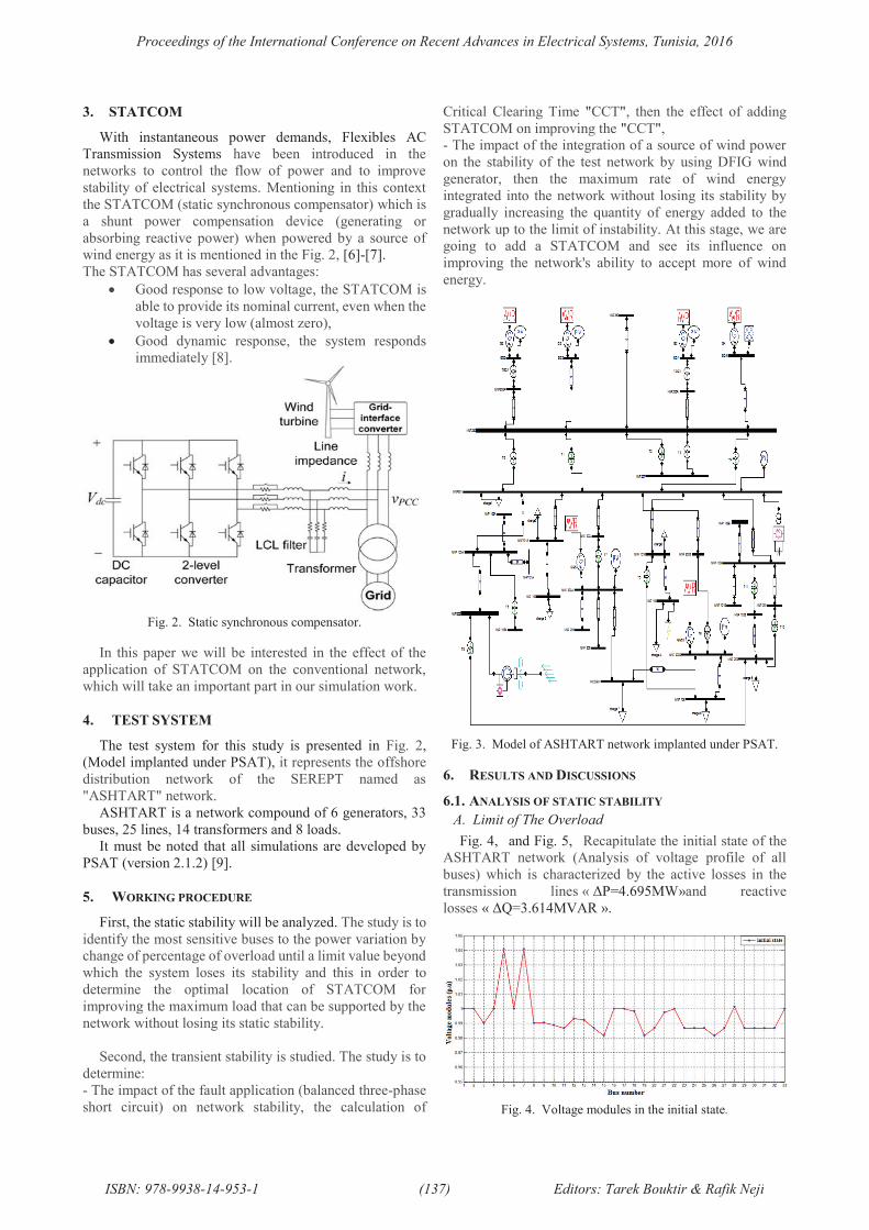
With instantaneous power demands, Flexibles AC
Transmission Systems have been introduced in the
networks to control the flow of power and to improve
stability of electrical systems. Mentioning in this context
the STATCOM (static synchronous compensator) which is
a shunt power compensation device (generating or
absorbing reactive power) when powered by a source of
wind energy as it is mentioned in the Fig. 2, [6]-[7].
The STATCOM has several advantages:
· Good response to low voltage, the STATCOM is
able to provide its nominal current, even when the
voltage is very low (almost zero),
· Good dynamic response, the system responds
immediately [8].
Fig. 2. Static synchronous compensator.
In this paper we will be interested in the effect of the
application of STATCOM on the conventional network,
which will take an important part in our simulation work.
4. TEST SYSTEM
The test system for this study is presented in Fig. 2,
(Model implanted under PSAT), it represents the offshore
distribution network of the SEREPT named as
"ASHTART" network.
ASHTART is a network compound of 6 generators, 33
buses, 25 lines, 14 transformers and 8 loads.
It must be noted that all simulations are developed by
PSAT (version 2.1.2) [9].
5. WORKING PROCEDURE
First, the static stability will be analyzed. The study is to
identify the most sensitive buses to the power variation by
change of percentage of overload until a limit value beyond
which the system loses its stability and this in order to
determine the optimal location of STATCOM for
improving the maximum load that can be supported by the
network without losing its static stability.
Second, the transient stability is studied. The study is to
determine:
- The impact of the fault application (balanced three-phase
short circuit) on network stability, the calculation of
Critical Clearing Time "CCT", then the effect of adding
STATCOM on improving the "CCT",
- The impact of the integration of a source of wind power
on the stability of the test network by using DFIG wind
generator, then the maximum rate of wind energy
integrated into the network without losing its stability by
gradually increasing the quantity of energy added to the
network up to the limit of instability. At this stage, we are
going to add a STATCOM and see its influence on
improving the network's ability to accept more of wind
energy.
Fig. 3. Model of ASHTART network implanted under PSAT.
6. RESULTS AND DISCUSSIONS
6.1. ANALYSIS OF STATIC STABILITY
A. Limit of The Overload
Fig. 4, and Fig. 5, Recapitulate the initial state of the
ASHTART network (Analysis of voltage profile of all
buses) which is characterized by the active losses in the
transmission lines « ΔP=4.695MW»and reactive
losses « ΔQ=3.614MVAR ».
Fig. 4. Voltage modules in the initial state.
Proceedings of the International Conference on Recent Advances in Electrical Systems, Tunisia, 2016
ISBN: 978-9938-14-953-1 (137) Editors: Tarek Bouktir & Rafik Neji
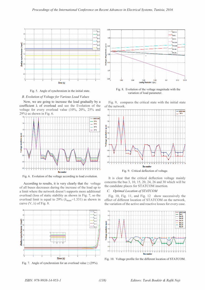
Fig. 5. Angle of synchronism in the initial state.
B. Evolution of Voltage for Various Load Values
Now, we are going to increase the load gradually by a
coefficient λ of overload and see the Evolution of the
voltage for every overload value (10%, 20%, 25% and
29%) as shown in Fig. 6.
Fig. 6. Evolution of the voltage according to load evolution.
According to results, it is very clearly that the voltage
of all buses decreases during the increase of the load up to
a limit where the network doesn’t supports more additional
overload (loss of static stability as shown in Fig. 7, so the
overload limit is equal to 29% ( !"#=1.331) as shown in
curve (V, λ) of Fig. 8.
Fig. 7. Angle of synchronism for an overload value ≥ (29%).
Fig. 8. Evolution of the voltage magnitude with the
variation of load parameter.
Fig. 9, compares the critical state with the initial state
of the network.
Fig. 9. Critical deflection of voltage.
It is clear that the critical deflection voltage mainly
concerns the bus 3, 10, 15, 20, 24, 26 and 30 which will be
the candidate places for STATCOM insertion.
C. Optimal Location of STATCOM
Fig. 10, Fig. 11, and Fig. 12 show successively the
effect of different location of STATCOM on the network,
the variation of the active and reactive losses for every case.
Fig. 10. Voltage profile for the different location of STATCOM.
Proceedings of the International Conference on Recent Advances in Electrical Systems, Tunisia, 2016
ISBN: 978-9938-14-953-1 (138) Editors: Tarek Bouktir & Rafik Neji
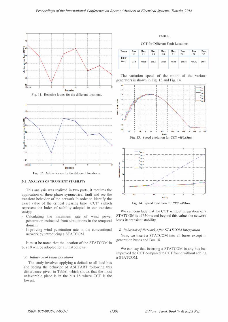
Fig. 11. Reactive losses for the different locations.
Fig. 12. Active losses for the different locations.
6.2. ANALYSIS OF TRANSIENT STABILITY
This analysis was realized in two parts, it requires the
application of three phase symmetrical fault and see the
transient behavior of the network in order to identify the
exact value of the critical clearing time "CCT" (which
represent the Index of stability adopted in our transient
study):
- Calculating the maximum rate of wind power
penetration estimated from simulations in the temporal
domain,
- Improving wind penetration rate in the conventional
network by introducing a STATCOM.
It must be noted that the location of the STATCOM in
bus 10 will be adopted for all that follows.
A. Influence of Fault Locations
The study involves applying a default to all load bus
and seeing the behavior of ASHTART following this
disturbance given in Table1 which shows that the most
unfavorable place is in the bus 18 where CCT is the
lowest.
TABLE I
CCT for Different Fault Locations
Buses Bus
10
Bus
11
Bus
15
Bus
18
Bus
21
Bus
26
Bus
28
Bus
32
CCT
(ms) 661.3 700.08 655.5 650.63 701.85 655.78 709.06 673.14
The variation speed of the rotors of the various
generators is shown in Fig. 13 and Fig. 14.
Fig. 13. Speed evolution for CCT =650.63ms.
Fig. 14. Speed evolution for CCT =651ms.
We can conclude that the CCT without integration of a
STATCOM is of 650ms and beyond this value, the network
loses its transient stability.
B. Behavior of Network After STATCOM Integration
Now, we insert a STATCOM into all buses except in
generation buses and Bus 18.
We can say that inserting a STATCOM in any bus has
improved the CCT compared to CCT found without adding
a STATCOM.
Proceedings of the International Conference on Recent Advances in Electrical Systems, Tunisia, 2016
ISBN: 978-9938-14-953-1 (139) Editors: Tarek Bouktir & Rafik Neji
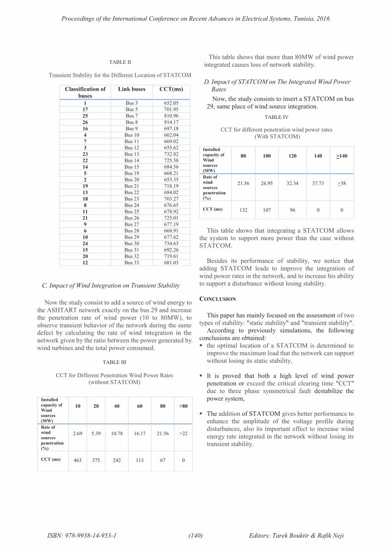
TABLE II
Transient Stability for the Different Location of STATCOM
Classification of
buses
Link buses CCT(ms)
1 Bus 3 652.05
17 Bus 5 701.95
25 Bus 7 810.96
26 Bus 8 914.17
16 Bus 9 697.18
4 Bus 10 662.04
7 Bus 11 669.02
3 Bus 12 655.62
23 Bus 13 732.82
22 Bus 14 725.58
14 Bus 15 684.56
5 Bus 19 668.21
2 Bus 20 653.35
19 Bus 21 718.19
13 Bus 22 684.02
18 Bus 23 703.27
8 Bus 24 676.65
11 Bus 25 678.92
21 Bus 26 725.01
9 Bus 27 677.19
6 Bus 28 668.91
10 Bus 29 677.62
24 Bus 30 734.63
15 Bus 31 692.26
20 Bus 32 719.61
12 Bus 33 681.03
C. Impact of Wind Integration on Transient Stability
Now the study consist to add a source of wind energy to
the ASHTART network exactly on the bus 29 and increase
the penetration rate of wind power (10 to 80MW), to
observe transient behavior of the network during the same
defect by calculating the rate of wind integration in the
network given by the ratio between the power generated by
wind turbines and the total power consumed.
TABLE III
CCT for Different Penetration Wind Power Rates
(without STATCOM)
This table shows that more than 80MW of wind power
integrated causes loss of network stability.
D. Impact of STATCOM on The Integrated Wind Power
Rates
Now, the study consists to insert a STATCOM on bus
29, same place of wind source integration.
TABLE IV
CCT for different penetration wind power rates
(With STATCOM)
Installed
capacity of
Wind
sources
(MW)
80 100 120 140 >140
Rate of
wind
sources
penetration
(%)
21.56 26.95 32.34 37.73 >38
CCT (ms) 132 107 96 0 0
This table shows that integrating a STATCOM allows
the system to support more power than the case without
STATCOM.
Besides its performance of stability, we notice that
adding STATCOM leads to improve the integration of
wind power rates in the network, and to increase his ability
to support a disturbance without losing stability.
CONCLUSION
This paper has mainly focused on the assessment of two
types of stability: "static stability" and "transient stability".
According to previously simulations, the following
conclusions are obtained:
§ the optimal location of a STATCOM is determined to
improve the maximum load that the network can support
without losing its static stability,
§ It is proved that both a high level of wind power
penetration or exceed the critical clearing time "CCT"
due to three phase symmetrical fault destabilize the
power system,
§ The addition of STATCOM gives better performance to
enhance the amplitude of the voltage profile during
disturbances, also its important effect to increase wind
energy rate integrated in the network without losing its
transient stability.
Installed
capacity of
Wind
sources
(MW)
10 20 40 60 80 >80
Rate of
wind
sources
penetration
(%)
2.69 5.39 10.78 16.17 21.56 >22
CCT (ms) 463 375 242 113 67 0
Proceedings of the International Conference on Recent Advances in Electrical Systems, Tunisia, 2016
ISBN: 978-9938-14-953-1 (140) Editors: Tarek Bouktir & Rafik Neji
REFERENCES
[1] A.D. Hansen, P. Sørensen, F. Iov, F. Blaabjerg,
"Initialisation of Grid-Connected Wind Turbine Models in
Power-System Simulations," Wind Engineering, pp. 21-38,
2003.
[2] R. Datta and V. T. Ranganathan, "Variable-speed wind
power generation using doubly fed wound rotor induction
machine-a comparison with alternative schemes," Energy
Conversion, IEEE Transactions on, vol. 17, pp. 414-421,
2002.
[3] Festo Didactic Ltée/Ltd, "Principles of Doubly-Fed
Induction Generators (DFIG)," Quebec, Canada 2011.
[4] M. Edrah, A. Elansari and O.G. Mrehel, "Impact of
DFIG based Wind Farms on Transient Stability of Power
Systems," Electrical Engineering, 2016.
[5] M. V. Nunes, J. Peas Lopes, H. H. Zurn, U. H. Bezerra,
and R. G. Almeida, "Influence of the variable-speed wind
generators in transient stability margin of the conventional
generators integrated in electrical grids," Energy
Conversion, IEEE Transactions on, vol. 19, pp. 692-701,
2004.
[6] M.K.Sebaa, "Commande intelligente pour
l'amélioration de la stabilité dynamique des réseaux
d'énergie électrique," Thèse de Doctorat en
Electrotechnique de Université des Sciences & des
Technologies Houari Boumediene (USTHB), Algérie, 15
Septembre 2008.
[7] N. Djemai, "Optimisation de l’intégration des
ressources énergétiques décentralisées(RED) aux réseaux
de distribution dans un marché de l’électricité dérégulé, "
Thèse de doctorat en science .Université Mohamed Khider
– Biskra, 2015.
[8] S.A. Al-Mawsawi, " Comparing and evaluating the
voltage regulation of a UPFC and STATCOM , " Electric
Power & Energy systems, Elsevier, No. 25, pp. 1-6, 2003.
[9] PSAT HELP 2011.
Proceedings of the International Conference on Recent Advances in Electrical Systems, Tunisia, 2016
ISBN: 978-9938-14-953-1 (141) Editors: Tarek Bouktir & Rafik Neji