ohmic and rf heated itbs in alcator c-mod · 2011-04-20 · ohmic and rf heated itbs in alcator...
TRANSCRIPT

Ohmic and RF Heated ITBs in Alcator C-Mod
William L. Rowan, Igor O. BespamyatnovFusion Research Center, The University of Texas at Austin
C.L. Fiore, A. Dominguez, A.E. Hubbard, A. Ince-Cushman,M.J. Greenwald, L. Lin, E.S. Marmar, M. Reinke, J.E. Rice,
K. ZhurovichMIT Plasma Science and Fusion Center
Session NP8: Poster Session V, Abstract: NP8.00072 9:30am - 12:30pm, Wednesday, November 14, 2007 Rosen Centre Hotel - Grand Ballroom
49th Annual Meeting of the Division of Plasma Physicsof the American Physical Society
November 12–16 2007; Orlando, FL
Ohmic and RF Heated ITBsin Alcator C-Mod
Internal transport barrier (ITB) plasmas can arise as a result of RFheating or spontaneously in Ohmic Alcator C-Mod plasmas. Theoperational prescription for the ITB includes formation of an EDA H-mode. In Ohmic ITBs, the toroidal magnetic field is ramped down andthen increased. Like ITBs generated with off-axis ICRF heating, OhmicITBs have peaked pressure profiles which can be suppressed by on-axisICRF heating. Recent work on onset conditions for the ICRF generatedITB (K. Zhurovich, et al., Nuclear Fusion 47, 1220 (2007))demonstrates that the broadening of the ion temperature profile due tooff-axis ICRF reduces the ion temperature gradient and suppresses theITG-instability-driven particle flux. The object of this study is to addadditional impurity transport information to the ITB description andto examine the characteristics of ITBs to find whether this model foronset is supported.

Summary
Two ITB modes in Alcator C-Mod– Ohmic, no auxiliary heating– Auxiliary heated: off-axis ICRF– Common features previously identified
» EDA H-Mode precursor required for both» Peaked pressure profiles evolve in both» Central ICRF heating suppresses peaking
New results are for ITBs with off-axis ICRF– New boron impurity profiles are reported and used to study
impurity transport at the onset of the ITB» Inward advection is enhanced over diffusion during the
ITB» Impurity transport approaches neoclassical
– Clear profile Ti increased but cannot confidently interpret aprofile broadening
– ITB gradient for nz is inboard of gradient for Ti

ITB in C-Mod
Two ITB scenarios– Same precursor-plasma target: EDA H-mode– Ohmic: requires a BT ramp– ICRF: Off axis deposition
Very similar characteristics– Form from an H-mode– Strong pressure profile peaking– Peaking can be clamped by deposition of central ICRF power
Results from either will apply to the other There are advantages of studying one in preference to the other
– ICRF deposition complicates the transport analysis– ICRF deposition has more operational similarities to ITBs on
other devices

Ohmic ITB
H-ModeTransition
ITB
TeTS
neTS
BT
ne peaking
ne_L(4)
Hα
NoteBT Ramp

Auxiliary Heated ITBs
Off-axis ICRF deposition ITB forms from EDA H-mode
plasma ITB is characterized by
peaking of the electron densityprofile. The change of theelectron temperature is lessdramatic
Similar ITB can be formed inan Ohmic plasma
H-Mode
ITB
nepeaking
Tepeaking

Off-axis ICRF and Improved Confinement
Off-axis ICRF deposition leads to ITBformation
For the results shown here, depositionwas on the high field side.0.55 < R (m) < 0.6(vertical dashed lines)
Deposition can be on the low field side. Improved impurity transport is
observed between the two vertical lineson the low field side
Improved impurity transport on fluxsurfaces in-board of surfaces on whichthe heating is resonant.
Ti gradient just out-board of thegradient
ICRF Resonance Improved boron confinement

Compare ne and Te for ITBs
ITB characterized by peaking in the pressure profile for ρ < 0.6 Density peaking is dominant contributor Peaking can be clamped by deposition of central RF
(Fiore, et al., POP)
H-modeITB
H-mode
ITB
Ohmic ITB Auxiliary Heated ITB

Ion TemperatureITB foot ICRF Resonance Range
ITBImpurityGradientRegion
Ion Temperature
Ti profile changes when the plasma transitions from H-mode to ITB The Ti gradient is just outside the ICRF deposition and clearly
outside the ITB foot as defined by the electron density profile. In-board of the gradient, Ti during ITB is larger than Ti in H-Mode The Ti increase is well developed at the location of the impurity
gradient enhancements

Impurity Transport in an ITB
The current work extends earlier C-Mod impurity transportresearch (J. W. Rice, et al., Nuclear Fusion 42 ,510 (2002)) with localmeasurements of lighter ions.
New measurements of fully stripped B+5 profiles with spatial andtemporal resolution are reported here.
In the earlier work on C-Mod, chord-averaged measurements ofpuffed argon ions were reproduced in numerical simulations ofimpurity transport to characterize the transport.
This measurement is local. There is just one boron ion present atthe measurement locations. The analysis is therefore moretransparent.
Differences between light and heavy impurity transport have beenobserved in other experiments. (ref JET)

Measured B+5 Density
The boron density profile steepens during the ITB The deposition location for the ICRF is just outside the foot of the
gradient (see the configuration) The inset shows the MIST analysis for a similar discharge. In
measurement and simulation, B+5 is the only boron charge state forR < 0.87 m. B+5 density for R < 0.87 is the entire boron density.
H-mode
ITB
B+4
B+5 MIST1070831028
ICRF Resonance
ITBImpurityGradientRegion ITB Foot

Mag
netic
axi
s
H-modeITB
1070831028
Measured Electron Density
The boron density profile steepens during the ITB The heating location for the ICRF is predominately just outside the
foot of the ne gradient (see the configuration)
ICRF Resonance
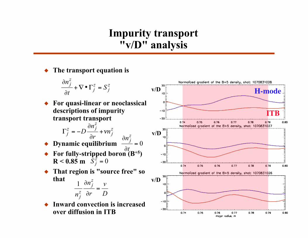
Impurity transport"v/D" analysis
The transport equation is
For quasi-linear or neoclassicaldescriptions of impuritytransport transport
Dynamic equilibrium For fully-stripped boron (B+5)
R < 0.85 m That region is "source free" so
that
Inward convection is increasedover diffusion in ITB
zj
zj
zj
St
n=!•"+
#
#
zj
zjz
j nr
nD !+
"
"#=$
0=!
!
t
nzj
0=zjS
D
v
r
n
n
zj
zj
=!
!1
H-mode
ITB
v/D
v/D
v/D

Is B+5 neoclassical?
Is B+5 neoclassical?-or-Can it be shown to obey neoclassical descriptions?
The diffusion coefficient is The convection coefficient is purely neoclassical Limit collisions of the impurity to collisions with the main plasma
ion, D+ in this case TD=Tz
!
D = Dneo
+Dan
!
v = vneo
!
vneo
= Dneo
ZI
ZD
1
nD
dnD
dr"H
1
TD
dTD
dr
#
$ %
&
' ( , 0.2 ) H ) 0.5
!
1
nZ
dnZ
dr=1
nD
dnD
dr
ZI
ZD
Dneo
Dneo
+ Dan
1"H#D( )
!
"D
=
1
TD
dTD
dr
1
nD
dnD
dr
#1

Is the transport neoclassical?
B+5 is neoclassical over a narrow range in-board of the ITB at thefoot
For this, use Dan << Dneo
!
1
nZ
dnZ
dr
1
nD
dnD
dr
=ZI
ZD
1"H( ) # 2.5 " 4.5
ITB1070831028
1070831027
1070831026
( )HZI
!1
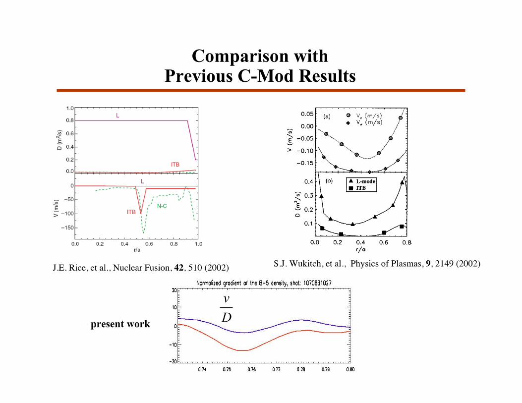
Comparison withPrevious C-Mod Results
J.E. Rice, et al., Nuclear Fusion, 42, 510 (2002)
D
v
S.J. Wukitch, et al., Physics of Plasmas, 9, 2149 (2002)
present work
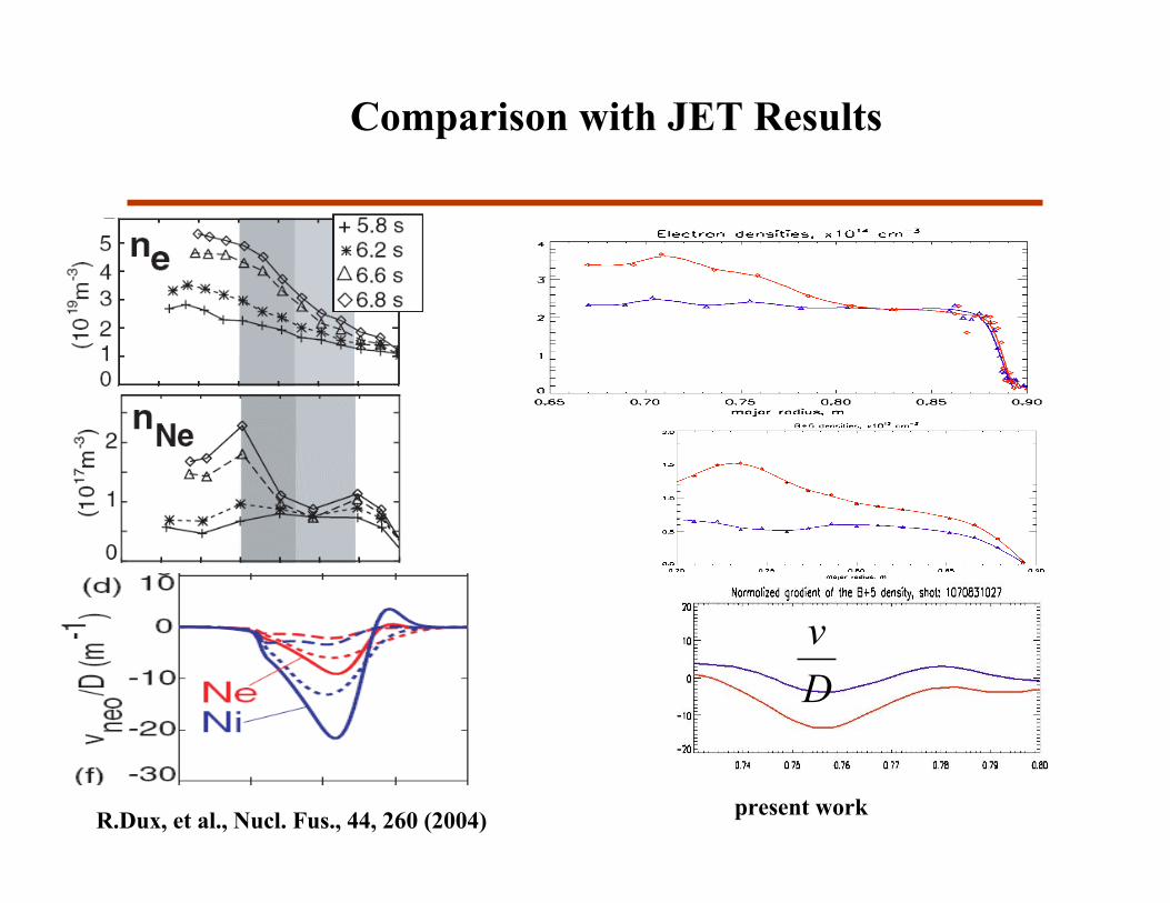
Comparison with JET Results
R.Dux, et al., Nucl. Fus., 44, 260 (2004)
D
v
present work
Summary
Confinement of light impurities is improved during ITB– Inward convection is enhanced relative to diffusion, or
equivalently, diffusion is reduced relative to inward convection.– Transport for boron is neoclassical over a limited range of the
plasma radius.– Further confirmation of ITB particle transport similarities
between C-Mod and other devices. Ti profiles change during the transition from H-mode to ITB.
– Ti increases on flux surfaces connected to the ICRF resonanceregion.
– Ti increases out-board of the ITB foot (defined using ne(R)) andof the region where the light impurity gradient steepens
Additional experiments planned for the next campaign.