oil leak from camshaft housing - fixed-opsmedia.fixed-ops.com/toy_servicebulletins/sb0321t08.pdf ·...
TRANSCRIPT

T-SB-0321-08 October 22, 2008
Oil Leak From Camshaft Housing
ServiceCategory Engine/Hybrid System
Section Engine Mechanical Market USA
Applicability
YEAR(S) MODEL(S) ADDITIONAL INFORMATION
2008 Highlander
Introduction
Some 2008 model year Highlander vehicles may display evidence of a small oil leak located at oneor both of the camshaft housing sub-assemblies. Please use the repair procedure below to addresscustomer concerns.
Production Change Information
This TSB applies to vehicles produced BEFORE the Production Change Effective VINs shown below.
MODEL PLANT DRIVETRAIN PRODUCTION CHANGE EFFECTIVE VIN
2WD JTEDS4#A*82010359Highlander TMK
4WD JTEES4#A*82016371
Warranty Information
OF CODE DESCRIPTION TYPE TIME OFP T1 T2
EG7045 2WD 17.1
EG7046R & R RH and LH Camshaft Housing
Sub-assemblies 4WD 17.611103-3102#11104-3102# 65 48
APPLICABLE WARRANTY• This repair is covered under the Toyota Powertrain Warranty. This warranty is in effect for 60
months or 60,000 miles, whichever occurs first, from the vehicle’s in-service date.
• Warranty application is limited to correction of a problem based upon a customer’s specificcomplaint.
© 2008 Toyota Motor Sales, USA Page 1 of 63

T-SB-0321-08 October 22, 2008 Page 2 of 63
Oil Leak From Camshaft Housing
Required Tools & Equipment
SPECIAL SERVICE TOOLS (SST’S) PART NUMBER QTY
Oil Filter Wrench* 09228-06500-02 1
Crankshaft Pulley Holding Tool* 09213-70011-01 1
Companion Flange Holding Tool*
NOTE: All components from this kit/set are required.09330-00021 1
Universal Puller Set “C”*
NOTE: All components from this kit/set are required.09950-50013-01 1
Gasket Seal Cutter 09032-00100 1
* Essential SST.
NOTEAdditional SSTs may be ordered by calling SPX/OTC at 1-800-933-8335.
REQUIRED MATERIAL PART NUMBER MODEL DETAIL QUANTITY
Three Bond 1324 or Equivalent – – As Needed
FIPG Sealant or Equivalent 08826-00080 – As Needed
Toyota Genuine Seal Packing Black, ThreeBond 1207B, or Equivalent – – As Needed
Toyota Genuine Seal Packing Black 1282B,Three Bond 1282B, or Equivalent – – As Needed
Toyota Genuine Adhesive 1344, Three Bond1344, or Equivalent – – As Needed
ILSAC GF-4 Multi-grade SAE 5W-30 00279-1QT5W-01 – 6.0 U.S. qts.(5.7 liters)
Standard w/RearHeater
11.6 U.S. qts.(11.0 liters)
Standard w/o RearHeater
9.3 U.S. qts.(8.8 liters)
Towing Packagew/Rear Heater
12.4 U.S. qts.(11.7 liters)
Super Long Life Coolant (SLLC) 00272-SLLC2
Towing Packagew/o Rear Heater
10.1 U.S. qts.(9.5 liters)
© 2008 Toyota Motor Sales, USA

T-SB-0321-08 October 22, 2008 Page 3 of 63
Oil Leak From Camshaft Housing
Required Tools & Equipment (Continued)
REQUIRED EQUIPMENT SUPPLIER PART NUMBER QTY
R-134a Refrigerant Recovery/Recycling Machine ADE Robinair ROB34200*(or equivalent) 1
NOTEAdditional refrigerant service equipment may be ordered by calling Toyota Approved DealerEquipment (ADE) at 1-800-368-6787.
Parts Information
PREVIOUS PART NUMBER CURRENT PART NUMBER PART NAME QTY
11103-31020
11103-3102111103-31022 Housing Sub-assembly, Camshaft, RH 1
11104-31020
11104-3102111104-31022 Housing Sub-assembly, Camshaft, LH 1
17176-0P020 Same Gasket, Air Surge Tank to Intake Manifold 3
17177-0P020 Same Gasket, Intake Manifold to Head, No. 1 1
17178-0P020 Same Gasket, Intake Manifold to Head, No. 2 1
11159-0P010 Same Gasket, Camshaft Bearing Cap Oil Hole 4
90430-A0001 Same O-ring (standard part) 2
90430-12031 Same Gasket, Oil Pan Drain Plug 1
15147-0P020 Same Gasket, Oil Strainer 1
12151-0P010 Same Gasket, Oil Pan 2
96721-19010 Same O-ring, for Oil Level Gauge Guide, No. 2 1
90301-12018 Same O-ring, for Oil Level Gauge Guide 1
15193-0P010 Same Gasket, Oil Pump 1
11213-0P010 Same Gasket, Cylinder Head Cover 1
11214-0P040 Same Gasket, Cylinder Head Cover No. 2 2
90430-16016 Same Gasket, Oil Pipe No. 2 2
90430-16012 90430-16017 Gasket, Oil Pipe No. 1 4
90311-A0005 Same Seal, Oil, for Timing Gear Case 1
11328-0P010 Same Gasket, Timing Gear Cover 1
96761-24021 Same O-ring (standard part), Coolant Pipe 1
90301-67004 Same O-ring, for Oil Cooler 1*
11496-31010 Same Gasket, Oil Hole Cover 1*
© 2008 Toyota Motor Sales, USA
T-SB-0321-08 October 22, 2008 Page 4 of 63
Oil Leak From Camshaft Housing
Parts Information (Continued)
PREVIOUS PART NUMBER CURRENT PART NUMBER PART NAME QTY
16325-31010 Same Gasket, Water Inlet Housing No. 2 1
90080-43036 Same Gasket, Exhaust Pipe 1
04152-31090 Same Element Kit, Oil Filter 1
16271-0P010 Same Gasket, Water Pump 1
* Equipped with Towing Package (Oil Cooler)
Inspection Procedure
• If necessary, use an oil dye to confirm the source of the oil leak.
• Refer to the repair procedure below ONLY if the oil leak source is located at one or both of thecamshaft housings.
Repair Procedure: Dissasembly
Disassemble the engine to remove the timing cover and replace the RH and LH camshaft housingsub-assemblies.
1. Remove the engine assembly.
Refer to the Technical Information System (TIS), 2008 model year Highlander Repair Manual,Engine/Hybrid System - Engine Mechanical - “2GR-FE Engine Mechanical: Engine Assembly:Removal”.
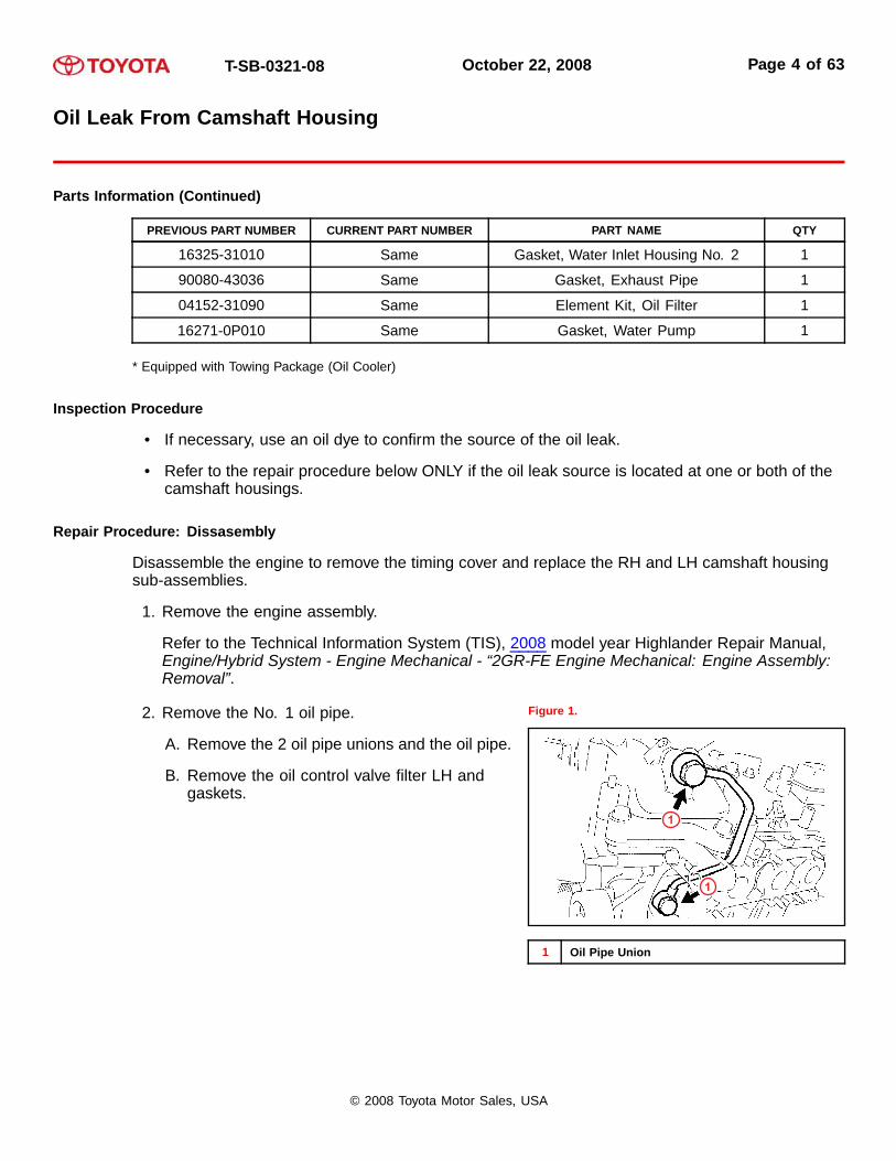
2. Remove the No. 1 oil pipe.
A. Remove the 2 oil pipe unions and the oil pipe.
B. Remove the oil control valve filter LH andgaskets.
Figure 1.
1
1
1 Oil Pipe Union
© 2008 Toyota Motor Sales, USA

T-SB-0321-08 October 22, 2008 Page 5 of 63
Oil Leak From Camshaft Housing
Repair Procedure: Dissasembly (Continued)
3. Remove the oil pipe.
A. Remove the bolt.
B. Remove the 2 oil pipe unions and the oil pipe.
C. Remove the oil control valve filter RH andgaskets.
Figure 2.
2
2
1
1 Bolt
2 Oil Pipe Union
4. Remove the oil filter element.
A. Remove the drain plug.
NOTEDo NOT remove the O-ring from the oil filtercap.
Figure 3.
1
1 Drain Plug
© 2008 Toyota Motor Sales, USA
T-SB-0321-08 October 22, 2008 Page 6 of 63
Oil Leak From Camshaft Housing
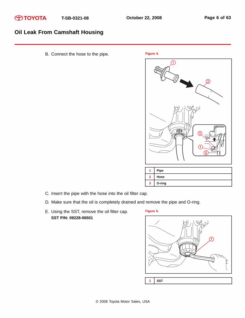
B. Connect the hose to the pipe. Figure 4.
2
3
1
2
1
1 Pipe
2 Hose
3 O-ring
C. Insert the pipe with the hose into the oil filter cap.
D. Make sure that the oil is completely drained and remove the pipe and O-ring.
E. Using the SST, remove the oil filter cap.SST P/N: 09228-06501
Figure 5.
1
1 SST
© 2008 Toyota Motor Sales, USA
T-SB-0321-08 October 22, 2008 Page 7 of 63
Oil Leak From Camshaft Housing
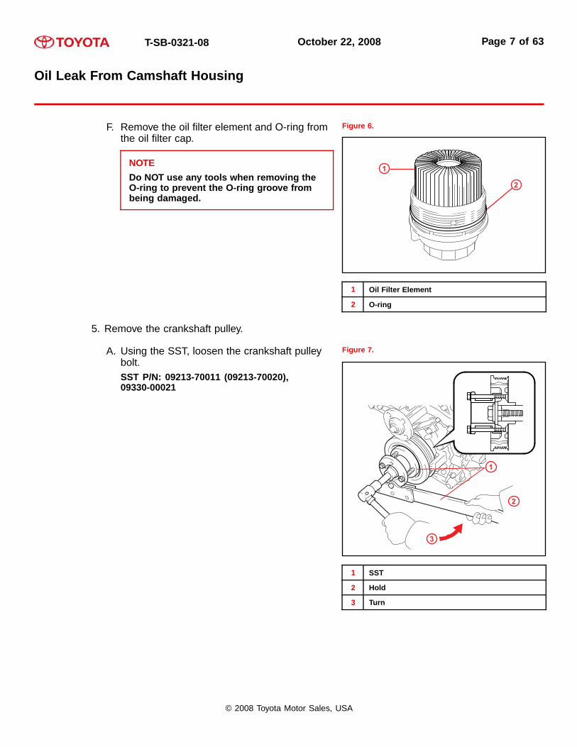
F. Remove the oil filter element and O-ring fromthe oil filter cap.
NOTEDo NOT use any tools when removing theO-ring to prevent the O-ring groove frombeing damaged.
Figure 6.
2
1
1 Oil Filter Element
2 O-ring
5. Remove the crankshaft pulley.
A. Using the SST, loosen the crankshaft pulleybolt.SST P/N: 09213-70011 (09213-70020),09330-00021
Figure 7.
1
2
3
1 SST
2 Hold
3 Turn
© 2008 Toyota Motor Sales, USA

T-SB-0321-08 October 22, 2008 Page 8 of 63
Oil Leak From Camshaft Housing
B. Using the SST, remove the crankshaft pulleybolt and crankshaft pulley.SST P/N: 09950-50013 (09951-05010,09952-05010, 09953-05020, 09954-05021)
Figure 8.
2
3
1
1 SST
2 Hold
3 Turn
6. Remove the oil cooler assembly (with oil cooler).
A. Remove the bolt, 2 clamps, and 4 clips anddisconnect the 2 water bypass hoses.
Figure 9.
© 2008 Toyota Motor Sales, USA

T-SB-0321-08 October 22, 2008 Page 9 of 63
Oil Leak From Camshaft Housing
B. Remove the union bolt, oil cooler assembly,and O-ring.
Figure 10.
7. Remove the No. 1 oil cooler bracket (with oilcooler) by removing the 3 bolts, 3 nuts, and oilcooler pipe.
Figure 11.
8. Remove the front engine mounting bracket No. 1LH by removing the 6 bolts.
Figure 12.
© 2008 Toyota Motor Sales, USA

T-SB-0321-08 October 22, 2008 Page 10 of 63
Oil Leak From Camshaft Housing
9. Remove the water inlet housing.
A. Remove the 2 bolts, nut, and water inlethousing.
Figure 13.
1
1
3
2
1 Bolt
2 Nut
3 Water Inlet Housing
B. Remove the 2 O-rings. Figure 14.
© 2008 Toyota Motor Sales, USA
T-SB-0321-08 October 22, 2008 Page 11 of 63
Oil Leak From Camshaft Housing
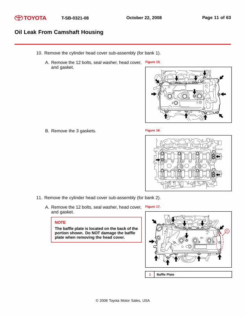
10. Remove the cylinder head cover sub-assembly (for bank 1).
A. Remove the 12 bolts, seal washer, head cover,and gasket.
Figure 15.
B. Remove the 3 gaskets. Figure 16.
11. Remove the cylinder head cover sub-assembly (for bank 2).
A. Remove the 12 bolts, seal washer, head cover,and gasket.
NOTEThe baffle plate is located on the back of theportion shown. Do NOT damage the baffleplate when removing the head cover.
Figure 17.
1
1 Baffle Plate
© 2008 Toyota Motor Sales, USA
T-SB-0321-08 October 22, 2008 Page 12 of 63
Oil Leak From Camshaft Housing
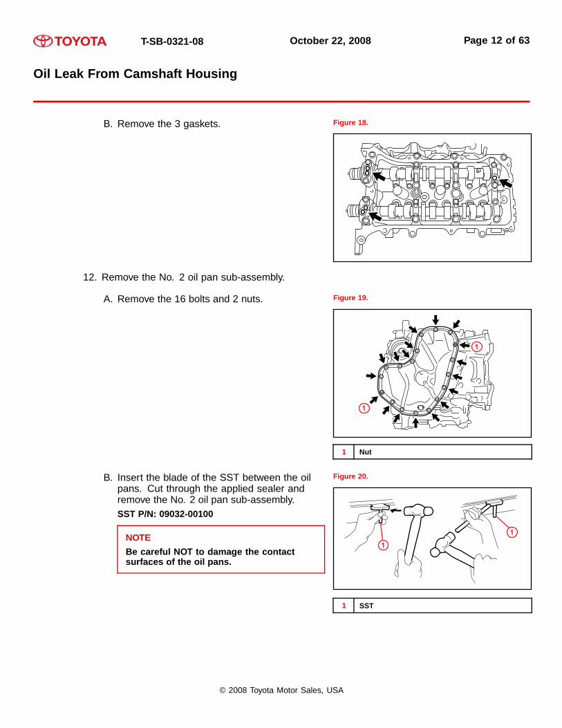
B. Remove the 3 gaskets. Figure 18.
12. Remove the No. 2 oil pan sub-assembly.
A. Remove the 16 bolts and 2 nuts. Figure 19.
1
1
1 Nut
B. Insert the blade of the SST between the oilpans. Cut through the applied sealer andremove the No. 2 oil pan sub-assembly.SST P/N: 09032-00100
NOTEBe careful NOT to damage the contactsurfaces of the oil pans.
Figure 20.
1
1
1 SST
© 2008 Toyota Motor Sales, USA

T-SB-0321-08 October 22, 2008 Page 13 of 63
Oil Leak From Camshaft Housing
13. Remove the oil strainer sub-assembly byremoving the bolt, 2 nuts, oil strainer, and gasket.
Figure 21.
1
2
2
1 Bolt
2 Nut
14. Remove the oil pan sub-assembly.
A. Remove the 16 bolts and 2 nuts.
HINTBe sure to clean the bolts and stud boltsand check the threads for cracks or otherdamage.
Figure 22.
1
1
1 Nut
© 2008 Toyota Motor Sales, USA
T-SB-0321-08 October 22, 2008 Page 14 of 63
Oil Leak From Camshaft Housing
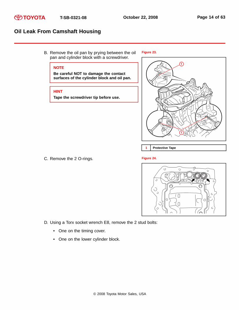
B. Remove the oil pan by prying between the oilpan and cylinder block with a screwdriver.
NOTEBe careful NOT to damage the contactsurfaces of the cylinder block and oil pan.
HINTTape the screwdriver tip before use.
Figure 23.
1
1
1 Protective Tape
C. Remove the 2 O-rings. Figure 24.
D. Using a Torx socket wrench E8, remove the 2 stud bolts:
• One on the timing cover.
• One on the lower cylinder block.
© 2008 Toyota Motor Sales, USA

T-SB-0321-08 October 22, 2008 Page 15 of 63
Oil Leak From Camshaft Housing
15. Remove the water pump assembly by removingthe 16 bolts, water pump, and gasket.
Figure 25.
16. Remove the timing chain cover sub-assembly.
A. Remove the 15 bolts and 2 nuts as shown. Figure 26.
1
1
1 Nut
© 2008 Toyota Motor Sales, USA

T-SB-0321-08 October 22, 2008 Page 16 of 63
Oil Leak From Camshaft Housing
B. Remove the timing chain cover by pryingbetween the timing chain cover and cylinderhead or cylinder block with a taped screwdriver.
NOTEBe careful NOT to damage the contactsurfaces of the cylinder head, cylinderblock, and chain cover.
Figure 27.
1
1
1 Protective Tape
C. Remove the 4 bolts, chain cover plate, and gasket.
D. Remove the gasket. Figure 28.
© 2008 Toyota Motor Sales, USA
T-SB-0321-08 October 22, 2008 Page 17 of 63
Oil Leak From Camshaft Housing
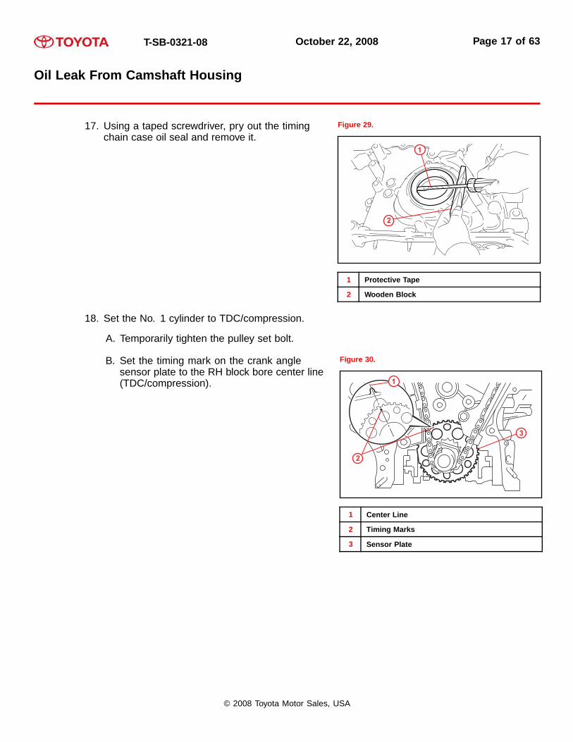
17. Using a taped screwdriver, pry out the timingchain case oil seal and remove it.
Figure 29.
1
2
1 Protective Tape
2 Wooden Block
18. Set the No. 1 cylinder to TDC/compression.
A. Temporarily tighten the pulley set bolt.
B. Set the timing mark on the crank anglesensor plate to the RH block bore center line(TDC/compression).
Figure 30.
1
3
2
1 Center Line
2 Timing Marks
3 Sensor Plate
© 2008 Toyota Motor Sales, USA

T-SB-0321-08 October 22, 2008 Page 18 of 63
Oil Leak From Camshaft Housing
C. Check that the timing marks of the camshafttiming gears are aligned with the timing marksof the bearing cap as shown in Figure 31.
If NOT, turn the crankshaft 1 revolution (360◦)and align the timing marks as above.
Figure 31.
1
1
1 Timing Marks
© 2008 Toyota Motor Sales, USA

T-SB-0321-08 October 22, 2008 Page 19 of 63
Oil Leak From Camshaft Housing
19. Remove the No. 1 chain tensioner assembly.
A. Move the stopper plate upward to releasethe lock, and push the plunger deep into thetensioner.
Figure 32.
14
2 2
3
3
1 Stopper Plate
2 Plunger
3 Push
4 Pin
B. Move the stopper plate downward to set the lock, and insert a pin of φ1.27 mm (0.05 in.) intothe stopper plate’s hole.
C. Remove the 2 bolts and chain tensioner. Figure 33.
20. Remove the chain tensioner slipper.
© 2008 Toyota Motor Sales, USA
T-SB-0321-08 October 22, 2008 Page 20 of 63
Oil Leak From Camshaft Housing
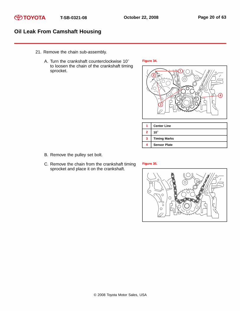
21. Remove the chain sub-assembly.
A. Turn the crankshaft counterclockwise 10◦to loosen the chain of the crankshaft timingsprocket.
Figure 34.
21
4
3
1 Center Line
2 10◦
3 Timing Marks
4 Sensor Plate
B. Remove the pulley set bolt.
C. Remove the chain from the crankshaft timingsprocket and place it on the crankshaft.
Figure 35.
© 2008 Toyota Motor Sales, USA
T-SB-0321-08 October 22, 2008 Page 21 of 63
Oil Leak From Camshaft Housing
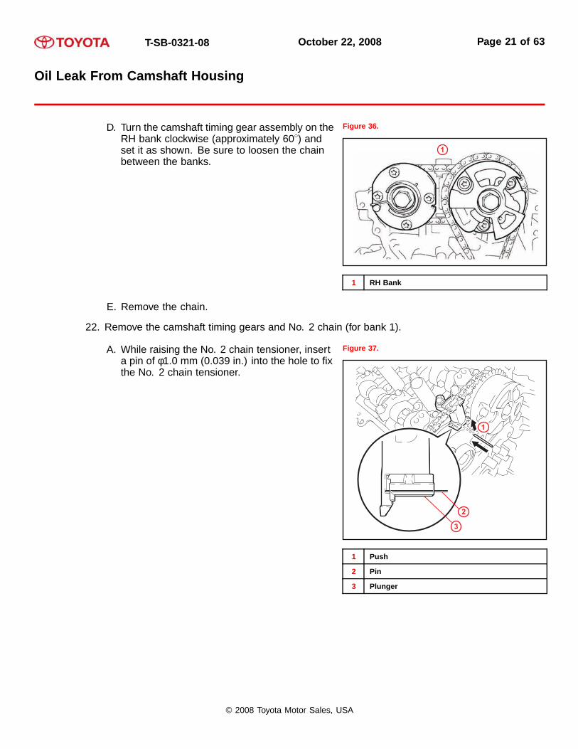
D. Turn the camshaft timing gear assembly on theRH bank clockwise (approximately 60◦) andset it as shown. Be sure to loosen the chainbetween the banks.
Figure 36.
1
1 RH Bank
E. Remove the chain.
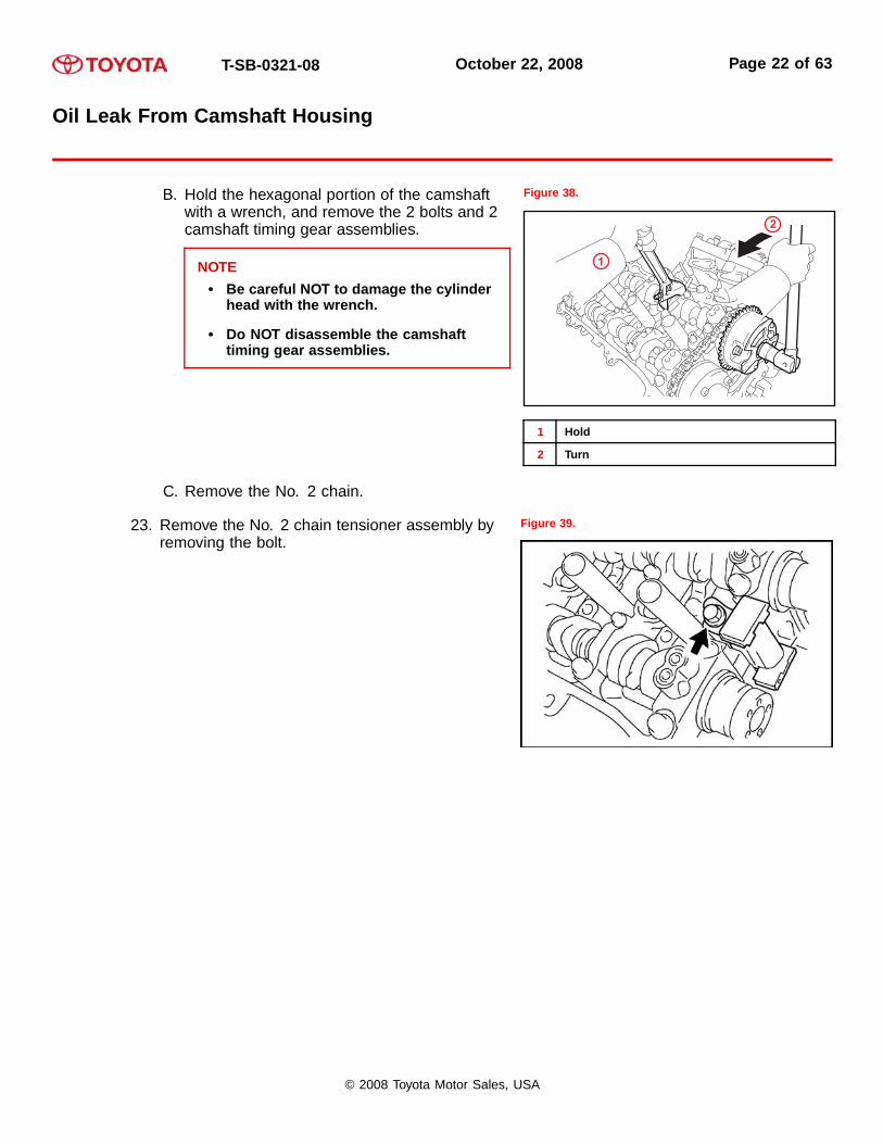
22. Remove the camshaft timing gears and No. 2 chain (for bank 1).
A. While raising the No. 2 chain tensioner, inserta pin of φ1.0 mm (0.039 in.) into the hole to fixthe No. 2 chain tensioner.
Figure 37.
1
3
2
1 Push
2 Pin
3 Plunger
© 2008 Toyota Motor Sales, USA
T-SB-0321-08 October 22, 2008 Page 22 of 63
Oil Leak From Camshaft Housing
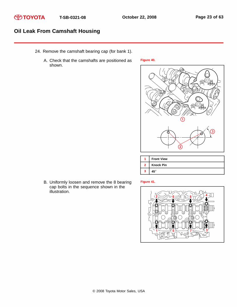
B. Hold the hexagonal portion of the camshaftwith a wrench, and remove the 2 bolts and 2camshaft timing gear assemblies.
NOTE• Be careful NOT to damage the cylinder
head with the wrench.
• Do NOT disassemble the camshafttiming gear assemblies.
Figure 38.
1
2
1 Hold
2 Turn
C. Remove the No. 2 chain.
23. Remove the No. 2 chain tensioner assembly byremoving the bolt.
Figure 39.
© 2008 Toyota Motor Sales, USA
T-SB-0321-08 October 22, 2008 Page 23 of 63
Oil Leak From Camshaft Housing
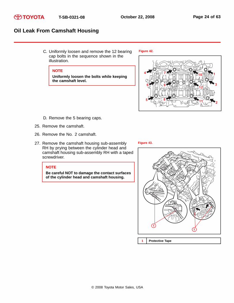
24. Remove the camshaft bearing cap (for bank 1).
A. Check that the camshafts are positioned asshown.
Figure 40.
1
3
2
1 Front View
2 Knock Pin
3 45◦
B. Uniformly loosen and remove the 8 bearingcap bolts in the sequence shown in theillustration.
Figure 41.
© 2008 Toyota Motor Sales, USA
T-SB-0321-08 October 22, 2008 Page 24 of 63
Oil Leak From Camshaft Housing
C. Uniformly loosen and remove the 12 bearingcap bolts in the sequence shown in theillustration.
NOTEUniformly loosen the bolts while keepingthe camshaft level.
Figure 42.
D. Remove the 5 bearing caps.
25. Remove the camshaft.
26. Remove the No. 2 camshaft.
27. Remove the camshaft housing sub-assemblyRH by prying between the cylinder head andcamshaft housing sub-assembly RH with a tapedscrewdriver.
NOTEBe careful NOT to damage the contact surfacesof the cylinder head and camshaft housing.
Figure 43.
11
1 Protective Tape
© 2008 Toyota Motor Sales, USA

T-SB-0321-08 October 22, 2008 Page 25 of 63
Oil Leak From Camshaft Housing
28. Remove the camshaft timing gears and No. 2 chain (for bank 2).
A. While pushing down the No. 3 chain tensioner,insert a pin of φ1.0 mm (0.039 in.) into the holeto fix the No. 3 chain tensioner.
Figure 44.
3
2
1
1 Push
2 Pin
3 Plunger
B. Hold the hexagonal portion of the camshaftwith a wrench, and remove the 2 bolts and 2camshaft timing gear assemblies.
NOTE• Be careful NOT to damage the cylinder
head with the wrench.
• Do NOT disassemble the camshafttiming gear assemblies.
Figure 45.
12
1 Hold
2 Turn
C. Remove the No. 2 chain.
© 2008 Toyota Motor Sales, USA
T-SB-0321-08 October 22, 2008 Page 26 of 63
Oil Leak From Camshaft Housing
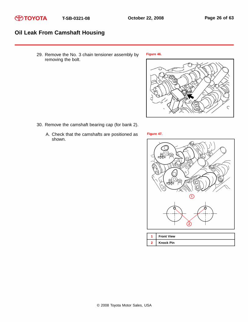
29. Remove the No. 3 chain tensioner assembly byremoving the bolt.
Figure 46.
30. Remove the camshaft bearing cap (for bank 2).
A. Check that the camshafts are positioned asshown.
Figure 47.
1
2
1 Front View
2 Knock Pin
© 2008 Toyota Motor Sales, USA

T-SB-0321-08 October 22, 2008 Page 27 of 63
Oil Leak From Camshaft Housing
B. Uniformly loosen and remove the 8 bearingcap bolts in the sequence shown in theillustration.
Figure 48. Loosening Sequence
4 8 6 2
73 5 1
C. Uniformly loosen and remove the 13 bearingcap bolts in the sequence shown in theillustration.
NOTEUniformly loosen the bolts while keepingthe camshaft level.
Figure 49. Loosening Sequence
410
1
312
13
9
8 2
7
6
511
D. Remove the 5 bearing caps.
31. Remove the No. 3 camshaft.
32. Remove the No. 4 camshaft.
© 2008 Toyota Motor Sales, USA
T-SB-0321-08 October 22, 2008 Page 28 of 63
Oil Leak From Camshaft Housing
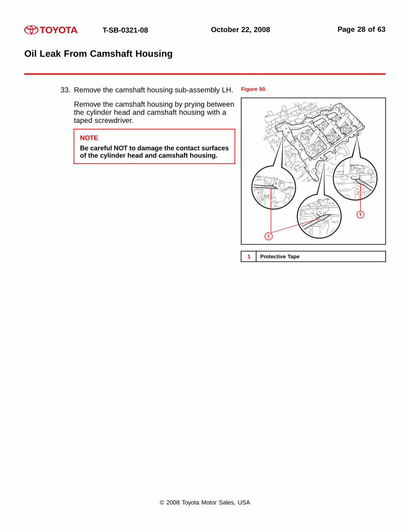
33. Remove the camshaft housing sub-assembly LH.
Remove the camshaft housing by prying betweenthe cylinder head and camshaft housing with ataped screwdriver.
NOTEBe careful NOT to damage the contact surfacesof the cylinder head and camshaft housing.
Figure 50.
1
1
1 Protective Tape
© 2008 Toyota Motor Sales, USA
T-SB-0321-08 October 22, 2008 Page 29 of 63
Oil Leak From Camshaft Housing
Repair Procedure: Reassembly
Reassemble the engine.
1. Install the camshaft bearing cap (for bank 1).
A. Apply engine oil to the camshaft journals, camshaft housing, and bearing caps.
B. Install the camshaft and No. 2 camshaft to the camshaft housing RH.
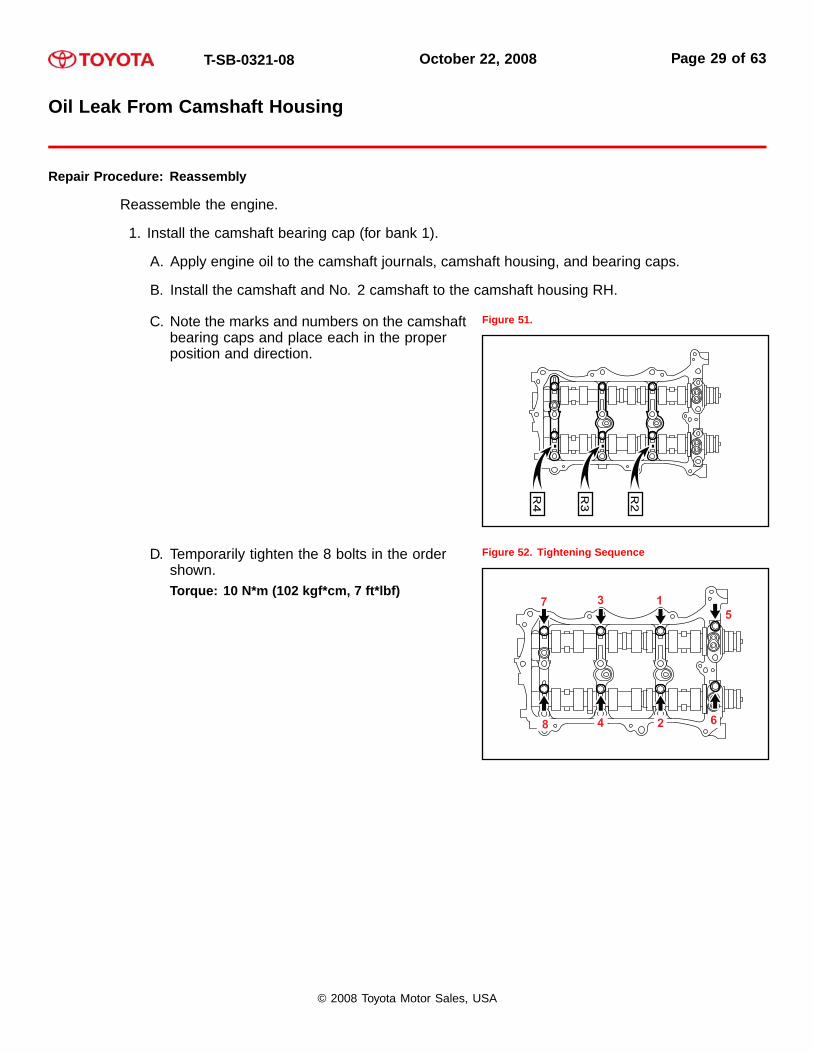
C. Note the marks and numbers on the camshaftbearing caps and place each in the properposition and direction.
Figure 51.
D. Temporarily tighten the 8 bolts in the ordershown.Torque: 10 N*m (102 kgf*cm, 7 ft*lbf)
Figure 52. Tightening Sequence
© 2008 Toyota Motor Sales, USA

T-SB-0321-08 October 22, 2008 Page 30 of 63
Oil Leak From Camshaft Housing
Repair Procedure: Reassembly (Continued)
2. Install the camshaft housing sub-assembly RH.
A. Make sure that the valve rocker arm is installedas shown.
Figure 53.
1
3
4
2
1 Valve Rocker Arm
2 Lash Adjuster
3 Valve Stem Cap
4 Valve Stem
B. Apply seal packing in a continuous line asshown.Seal packing:Toyota Genuine Seal Packing Black,Three Bond 1207B, or equivalentSeal diameter:3.5 - 4.5 mm (0.138 - 0.177 in.)
NOTE• Remove any oil from the contact
surface.
• Install the camshaft housingsub-assembly RH within 3 minutes.
• Do NOT start the engine for at LEAST 2hours after installing.
Figure 54.
1 Seal Packing (Diameter: 3.5 – 4.5 mm [0.138 –0.177 in.])
© 2008 Toyota Motor Sales, USA
T-SB-0321-08 October 22, 2008 Page 31 of 63
Oil Leak From Camshaft Housing
Repair Procedure: Reassembly (Continued)
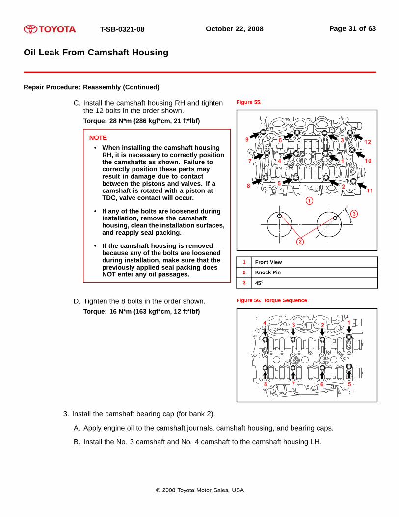
C. Install the camshaft housing RH and tightenthe 12 bolts in the order shown.Torque: 28 N*m (286 kgf*cm, 21 ft*lbf)
NOTE• When installing the camshaft housing
RH, it is necessary to correctly positionthe camshafts as shown. Failure tocorrectly position these parts mayresult in damage due to contactbetween the pistons and valves. If acamshaft is rotated with a piston atTDC, valve contact will occur.
• If any of the bolts are loosened duringinstallation, remove the camshafthousing, clean the installation surfaces,and reapply seal packing.
• If the camshaft housing is removedbecause any of the bolts are loosenedduring installation, make sure that thepreviously applied seal packing doesNOT enter any oil passages.
Figure 55.
1 Front View
2 Knock Pin
3 45◦
D. Tighten the 8 bolts in the order shown.Torque: 16 N*m (163 kgf*cm, 12 ft*lbf)
Figure 56. Torque Sequence
3. Install the camshaft bearing cap (for bank 2).
A. Apply engine oil to the camshaft journals, camshaft housing, and bearing caps.
B. Install the No. 3 camshaft and No. 4 camshaft to the camshaft housing LH.
© 2008 Toyota Motor Sales, USA

T-SB-0321-08 October 22, 2008 Page 32 of 63
Oil Leak From Camshaft Housing
Repair Procedure: Reassembly (Continued)
C. Note the marks and numbers on the camshaftbearing caps and place each in the properposition and direction.
Figure 57.
D. Temporarily tighten the 8 bolts in the ordershown.Torque: 10 N*m (102 kgf*cm, 7 ft*lbf)
Figure 58. Tightening Sequence
© 2008 Toyota Motor Sales, USA

T-SB-0321-08 October 22, 2008 Page 33 of 63
Oil Leak From Camshaft Housing
Repair Procedure: Reassembly (Continued)
4. Install the camshaft housing sub-assembly LH.
A. Make sure that the valve rocker arm is installedas shown.
Figure 59.
1
3
4
2
1 Valve Rocker Arm
2 Lash Adjuster
3 Valve Stem Cap
4 Valve Stem
B. Apply seal packing in a continuous line asshown.Seal packing:Toyota Genuine Seal Packing Black,Three Bond 1207B, or equivalentSeal diameter:3.5 - 4.5 mm (0.138 - 0.177 in.)
NOTE• Remove any oil from the contact
surface.
• Install the camshaft housingsub-assembly RH within 3 minutes.
• Do NOT start the engine for at LEAST 2hours after installing.
Figure 60.
1 Seal Packing (Diameter: 3.5 – 4.5 mm [0.138 –0.177 in.])
© 2008 Toyota Motor Sales, USA
T-SB-0321-08 October 22, 2008 Page 34 of 63
Oil Leak From Camshaft Housing
Repair Procedure: Reassembly (Continued)
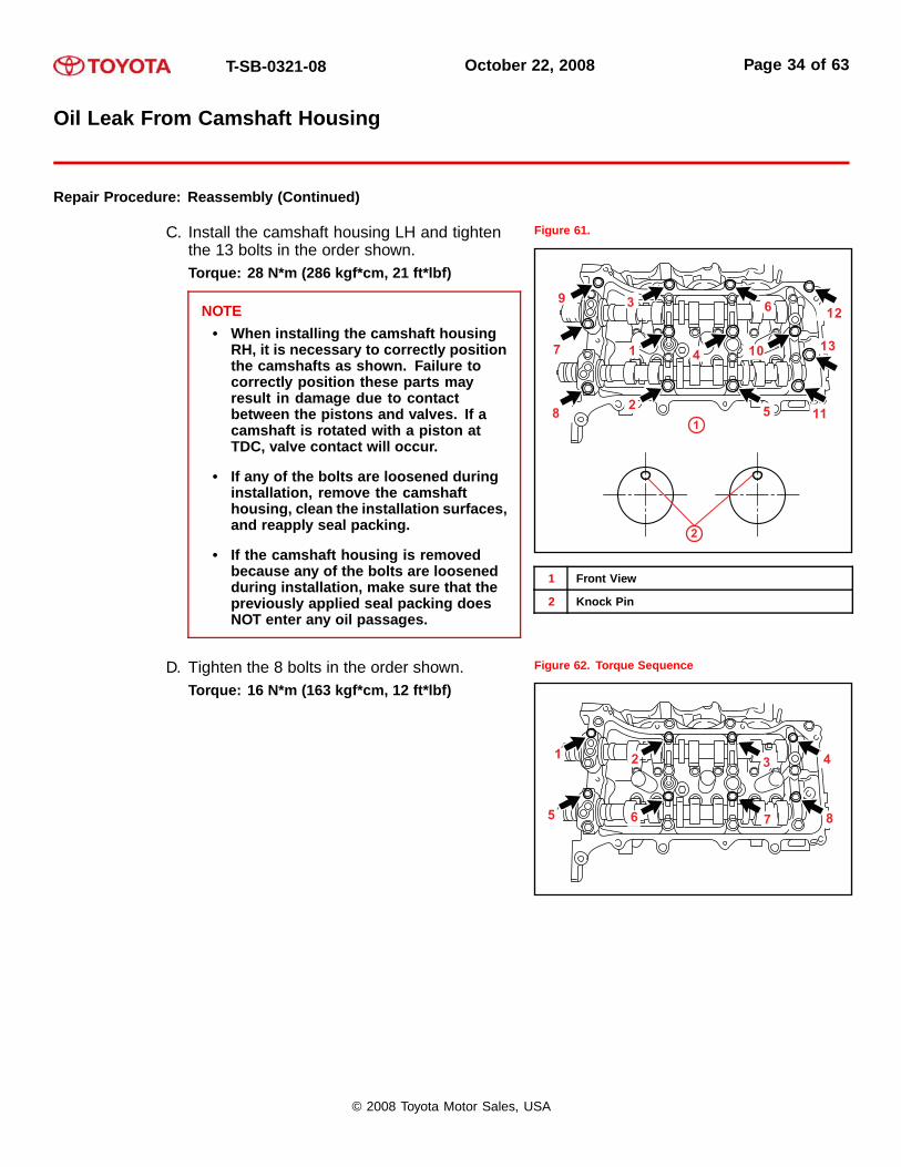
C. Install the camshaft housing LH and tightenthe 13 bolts in the order shown.Torque: 28 N*m (286 kgf*cm, 21 ft*lbf)
NOTE• When installing the camshaft housing
RH, it is necessary to correctly positionthe camshafts as shown. Failure tocorrectly position these parts mayresult in damage due to contactbetween the pistons and valves. If acamshaft is rotated with a piston atTDC, valve contact will occur.
• If any of the bolts are loosened duringinstallation, remove the camshafthousing, clean the installation surfaces,and reapply seal packing.
• If the camshaft housing is removedbecause any of the bolts are loosenedduring installation, make sure that thepreviously applied seal packing doesNOT enter any oil passages.
Figure 61.
1 Front View
2 Knock Pin
D. Tighten the 8 bolts in the order shown.Torque: 16 N*m (163 kgf*cm, 12 ft*lbf)
Figure 62. Torque Sequence
© 2008 Toyota Motor Sales, USA

T-SB-0321-08 October 22, 2008 Page 35 of 63
Oil Leak From Camshaft Housing
Repair Procedure: Reassembly (Continued)
5. Install the No. 2 chain tensioner assembly.
A. Install the No. 2 chain tensioner with the bolt.Torque: 21 N*m (214 kgf*cm, 15 ft*lbf)
B. While pushing in the tensioner, insert a pin ofφ1.0 mm (0.039 in.) into the hole to hold it.
Figure 63.
1
3
2
1 Push
2 Pin
3 Plunger
© 2008 Toyota Motor Sales, USA
T-SB-0321-08 October 22, 2008 Page 36 of 63
Oil Leak From Camshaft Housing
Repair Procedure: Reassembly (Continued)
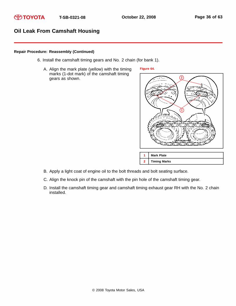
6. Install the camshaft timing gears and No. 2 chain (for bank 1).
A. Align the mark plate (yellow) with the timingmarks (1-dot mark) of the camshaft timinggears as shown.
Figure 64.
1 Mark Plate
2 Timing Marks
B. Apply a light coat of engine oil to the bolt threads and bolt seating surface.
C. Align the knock pin of the camshaft with the pin hole of the camshaft timing gear.
D. Install the camshaft timing gear and camshaft timing exhaust gear RH with the No. 2 chaininstalled.
© 2008 Toyota Motor Sales, USA
T-SB-0321-08 October 22, 2008 Page 37 of 63
Oil Leak From Camshaft Housing
Repair Procedure: Reassembly (Continued)
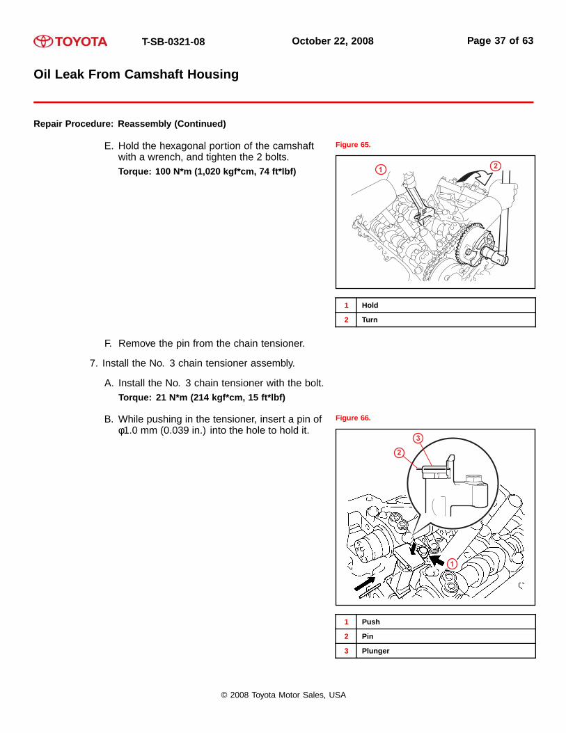
E. Hold the hexagonal portion of the camshaftwith a wrench, and tighten the 2 bolts.Torque: 100 N*m (1,020 kgf*cm, 74 ft*lbf)
Figure 65.
1 2
1 Hold
2 Turn
F. Remove the pin from the chain tensioner.
7. Install the No. 3 chain tensioner assembly.
A. Install the No. 3 chain tensioner with the bolt.Torque: 21 N*m (214 kgf*cm, 15 ft*lbf)
B. While pushing in the tensioner, insert a pin ofφ1.0 mm (0.039 in.) into the hole to hold it.
Figure 66.
3
2
1
1 Push
2 Pin
3 Plunger
© 2008 Toyota Motor Sales, USA

T-SB-0321-08 October 22, 2008 Page 38 of 63
Oil Leak From Camshaft Housing
Repair Procedure: Reassembly (Continued)
8. Install the camshaft timing gears and No. 2 chain (for bank 2).
A. Align the mark plate (yellow) with the timingmarks (2-dot mark) of the camshaft timinggears as shown.
Figure 67.
1 Mark Plate
2 Timing Marks
B. Apply a light coat of engine oil to the bolt threads and bolt seating surface.
C. Align the knock pin of the camshaft with the pin hole of the camshaft timing gear.
D. Install the camshaft timing gear and camshaft timing exhaust gear LH with the No. 2 chaininstalled.
© 2008 Toyota Motor Sales, USA

T-SB-0321-08 October 22, 2008 Page 39 of 63
Oil Leak From Camshaft Housing
Repair Procedure: Reassembly (Continued)
E. Hold the hexagonal portion of the camshaftwith a wrench, and tighten the 2 bolts.Torque: 100 N*m (1,020 kgf*cm, 74 ft*lbf)
Figure 68.
12
1 Hold
2 Turn
F. Remove the pin from the chain tensioner.
© 2008 Toyota Motor Sales, USA
T-SB-0321-08 October 22, 2008 Page 40 of 63
Oil Leak From Camshaft Housing
Repair Procedure: Reassembly (Continued)
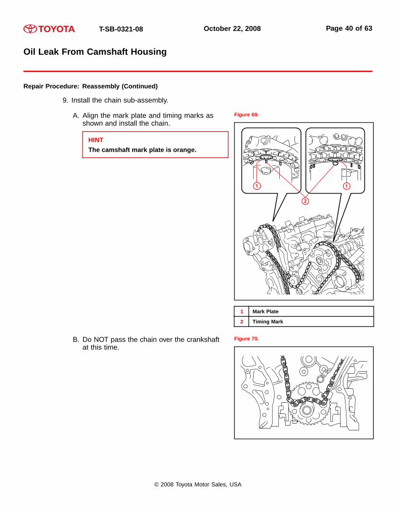
9. Install the chain sub-assembly.
A. Align the mark plate and timing marks asshown and install the chain.
HINTThe camshaft mark plate is orange.
Figure 69.
1 1
2
1 Mark Plate
2 Timing Mark
B. Do NOT pass the chain over the crankshaftat this time.
Figure 70.
© 2008 Toyota Motor Sales, USA

T-SB-0321-08 October 22, 2008 Page 41 of 63
Oil Leak From Camshaft Housing
Repair Procedure: Reassembly (Continued)
C. Turn the camshaft timing gear assembly onthe RH bank counterclockwise to tighten thechain between the banks.
NOTEWhen the idle sprocket is reused, alignthe chain plate with the mark where theplate had been in order to tighten the chainbetween the banks.
Figure 71.
1
1 Turn
Figure 72. When Idle Sprocket is Reused
1
3
2
1 Align
2 Chain Plate
3 Mark
© 2008 Toyota Motor Sales, USA

T-SB-0321-08 October 22, 2008 Page 42 of 63
Oil Leak From Camshaft Housing
Repair Procedure: Reassembly (Continued)
D. Align the mark plate and timing mark as shownand install the chain onto the crankshaft timingsprocket.
HINTThe crankshaft mark plate is yellow.
Figure 73.
1
2
1 Mark Plate
2 Timing Marks
E. Temporarily tighten the pulley set bolt.
F. Turn the crankshaft clockwise to set it to theRH block bore center line (TDC/compression).
Figure 74.
1
2
1 Center Line
2 Timing Marks
10. Install the chain tensioner slipper.
© 2008 Toyota Motor Sales, USA

T-SB-0321-08 October 22, 2008 Page 43 of 63
Oil Leak From Camshaft Housing
Repair Procedure: Reassembly (Continued)
11. Install the No. 1 chain tensioner assembly.
A. Move the stopper plate upward to releasethe lock, and push the plunger deep into thetensioner.
Figure 75.
1
2
1 Stopper Plate
2 Plunger
B. Move the stopper plate downward to set the lock, and insert a hexagon wrench into thehole of the stopper plate.
C. Install the chain tensioner with the 2 bolts.Torque: 10 N*m (102 kgf*cm, 7 ft*lbf)
Figure 76.
© 2008 Toyota Motor Sales, USA
T-SB-0321-08 October 22, 2008 Page 44 of 63
Oil Leak From Camshaft Housing
Repair Procedure: Reassembly (Continued)
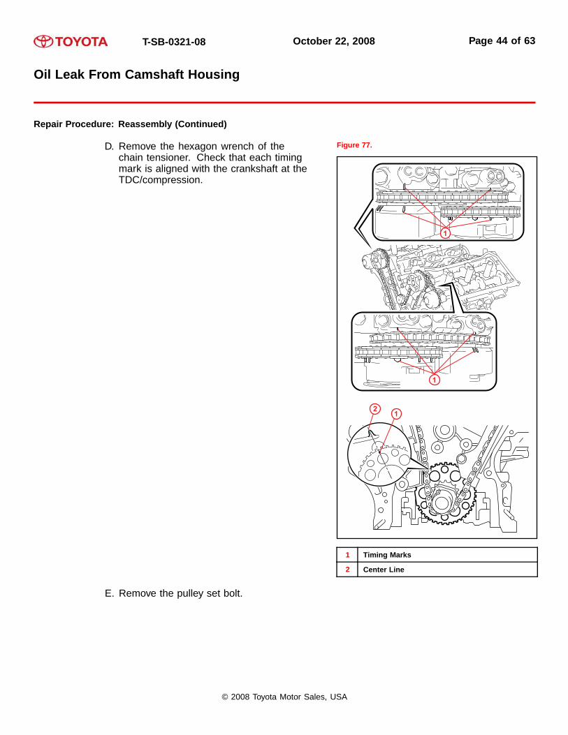
D. Remove the hexagon wrench of thechain tensioner. Check that each timingmark is aligned with the crankshaft at theTDC/compression.
Figure 77.
1
1
12
1 Timing Marks
2 Center Line
E. Remove the pulley set bolt.
© 2008 Toyota Motor Sales, USA

T-SB-0321-08 October 22, 2008 Page 45 of 63
Oil Leak From Camshaft Housing
Repair Procedure: Reassembly (Continued)
12. Install the timing chain case oil seal.
Using the SST, tap in a NEW oil seal until itssurface is flush with the timing gear case edge.SST P/N: 09223-22010, 09506-35010
NOTE• Keep the lip free of foreign matter.
• Do NOT tap on the oil seal at an angle.
• Make sure that the oil seal edge does NOTstick out of the timing chain case.
Figure 78.
1
1 SST
13. Install the water pump assembly.
Install a NEW gasket and the water pump withthe 8 bolts.Torque: 9.1 N*m (93 kgf*cm, 81 in*lbf)
NOTEBe sure to replace the bolts indicated by “A”with NEW ones or reuse them after applyingToyota Genuine Adhesive 1344, Three Bond1344, or equivalent.
Figure 79.
© 2008 Toyota Motor Sales, USA

T-SB-0321-08 October 22, 2008 Page 46 of 63
Oil Leak From Camshaft Housing
Repair Procedure: Reassembly (Continued)
14. Install the timing chain cover sub-assembly.
A. Apply seal packing in a continuous line to the engine unit as shown in Figure 80.Seal packing:Toyota Genuine Seal Packing Black, Three Bond 1207B, or equivalentSeal diameter:3.0 mm (0.118 in.)
Figure 80.
1
2
�
�
�
����
��
��
�
�
�
�
�
A
A A
AC
C
C
C
C
1 Seal Packing 2 3.0 mm or more (0.118 in.)
NOTE• Be sure to clean and degrease the contact surfaces, especially the surfaces indicated
by “C” in Figure 80.
• When the contact surfaces are wet, wipe them with an oil-free cloth before applyingseal packing.
• Install the chain cover within 3 minutes.
• Do NOT start the engine for at LEAST 2 hours after installing.
© 2008 Toyota Motor Sales, USA

T-SB-0321-08 October 22, 2008 Page 47 of 63
Oil Leak From Camshaft Housing
Repair Procedure: Reassembly (Continued)
B. Apply seal packing in a continuous line to the timing chain cover as shown below.Figure 81.
��
���
B - B
�� �
C - C
C
C
B
B
��
��
A - A
A
A
��
5.0 mm (0.197 in.)
2.0 – 3.0 mm (0.079 – 0.1 18 in.)
3.0 – 4.0 mm (0.118 – 0.158 in.)
1.0 – 2.0 mm (0.039 – 0.079 in.)
20 mm (0.787 in.)
20 mm (0.787 in.)
1
1
32 54
1 Be Sure to Apply Seal Packing
2 Dashed Line Area (Seal Packing: Toyota Genuine Seal Packing Black, Three Bond 1207B or Equivalent)
3 Continuous Line Area (Seal Packing: Toyota Genuine Seal Packing Black, Three Bond 1207B or Equivalent)
4 Alternate Long and Short Dashed Line Area (Seal Packing: Toyota Genuine Seal Packing 1282B, Three Bond1282B or Equivalent)
5 Diagonal Line Area (Seal Packing: Toyota Genuine Seal Packing Black, Three Bond 1207B or Equivalent)
© 2008 Toyota Motor Sales, USA

T-SB-0321-08 October 22, 2008 Page 48 of 63
Oil Leak From Camshaft Housing
Repair Procedure: Reassembly (Continued)
NOTE• When the contact surfaces are wet, wipe them with an oil-free cloth before applying
seal packing.
• Install the chain cover within 3 minutes and tighten the bolts within 15 minutes afterapplying seal packing.
• Do NOT start the engine for at LEAST 2 hours after installing.
Apply seal packing as follows:
AREA SEAL PACKING DIAMETER APPLICATION POSITION FROMINSIDE SEAL LINE
Continuous Line Area 4.5 mm (0.177 in.) or more 3.0 – 4.0 mm(0.118 – 0.158 in.)
Alternate Long andShort Dashed Line
Area3.5 mm (0.138 in.) or more 2.0 – 3.0 mm
(0.079 – 0.118 in.)
Dashed Line Area 3.5 mm (0.138 in.) or more 3.0 – 4.0 mm(0.118 – 0.158 in.)
��
Diagonal Line Area 6.0 mm (0.236 in.) or more 5.0 mm(0.197 in.)
© 2008 Toyota Motor Sales, USA

T-SB-0321-08 October 22, 2008 Page 49 of 63
Oil Leak From Camshaft Housing
Repair Procedure: Reassembly (Continued)
C. Install a NEW gasket. Figure 82.
D. Align the oil pump’s drive rotor spline and thecrankshaft as shown. Install the spline andchain cover to the crankshaft.
Figure 83.
12
1 Drive Rotor Spline
2 Crankshaft
© 2008 Toyota Motor Sales, USA

T-SB-0321-08 October 22, 2008 Page 50 of 63
Oil Leak From Camshaft Housing
Repair Procedure: Reassembly (Continued)
E. Temporarily tighten the timing chain cover with the 23 bolts and 2 nuts.Figure 84.
CC
C
C
C
B
C
CC
C
C
A
B
BB
BB
B
B
B
B
BB
1 1
3
4
4
4
553
2
1 Area 1
2 Area 2
3 Area 3
4 Area 4
5 Nut
Bolt Length:
ITEM LENGTH
Bolt A 40 mm (1.57 in.)
Bolt B 55 mm (2.17 in.)
Bolt C 25 mm (0.98 in.)
NOTEMake sure that there is NO oil on the bolt threads.
F. Fully tighten the bolts in this order: Area 1 and Area 2.Torque: 21 N*m (214 kgf*cm, 15 ft*lbf)
G. Fully tighten the bolts in this order: Area 3.Torque: 21 N*m (214 kgf*cm, 15 ft*lbf)
HINTTighten the bolts and nuts in the order as shown in Figure 84.
© 2008 Toyota Motor Sales, USA

T-SB-0321-08 October 22, 2008 Page 51 of 63
Oil Leak From Camshaft Housing
Repair Procedure: Reassembly (Continued)
H. Fully tighten the bolts in this order: Area 4.Torque:Bolt A:43 N*m (438 kgf*cm, 32 ft*lbf)Torque:Except Bolt A:21 N*m (214 kgf*cm, 15 ft*lbf)
HINTTighten the bolts and nuts in the order as shown in Figure 84.
I. Install a NEW gasket and the chain cover plate with the 4 bolts.Torque: 9.1 N*m (93 kgf*cm, 81 in*lbf)
15. Install the water inlet housing.
A. Install 2 NEW O-rings.
HINTApply a small amount of water or soapywater to O-ring “A” (shown in Figure 85)before installing it.
Figure 85.
A
B. Install the water inlet with the 2 bolts and nut.Torque: 10 N*m (102 kgf*cm, 7 ft*lbf)
NOTEBe careful that the O-ring does NOT getcaught between the parts.
Figure 86.
1
1 Nut
© 2008 Toyota Motor Sales, USA
T-SB-0321-08 October 22, 2008 Page 52 of 63
Oil Leak From Camshaft Housing
Repair Procedure: Reassembly (Continued)
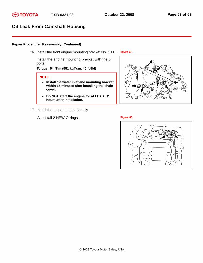
16. Install the front engine mounting bracket No. 1 LH.
Install the engine mounting bracket with the 6bolts.Torque: 54 N*m (551 kgf*cm, 40 ft*lbf)
NOTE• Install the water inlet and mounting bracket
within 15 minutes after installing the chaincover.
• Do NOT start the engine for at LEAST 2hours after installation.
Figure 87.
17. Install the oil pan sub-assembly.
A. Install 2 NEW O-rings. Figure 88.
© 2008 Toyota Motor Sales, USA
T-SB-0321-08 October 22, 2008 Page 53 of 63
Oil Leak From Camshaft Housing
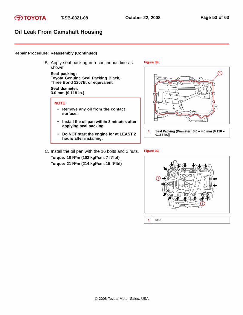
Repair Procedure: Reassembly (Continued)
B. Apply seal packing in a continuous line asshown.Seal packing:Toyota Genuine Seal Packing Black,Three Bond 1207B, or equivalentSeal diameter:3.0 mm (0.118 in.)
NOTE• Remove any oil from the contact
surface.
• Install the oil pan within 3 minutes afterapplying seal packing.
• Do NOT start the engine for at LEAST 2hours after installing.
Figure 89.
1
1 Seal Packing (Diameter: 3.0 – 4.0 mm [0.118 –0.156 in.])
C. Install the oil pan with the 16 bolts and 2 nuts.Torque: 10 N*m (102 kgf*cm, 7 ft*lbf)Torque: 21 N*m (214 kgf*cm, 15 ft*lbf)
Figure 90.
1
1
1 Nut
© 2008 Toyota Motor Sales, USA

T-SB-0321-08 October 22, 2008 Page 54 of 63
Oil Leak From Camshaft Housing
Repair Procedure: Reassembly (Continued)
18. Install the oil strainer sub-assembly.
Install a NEW gasket and the oil strainer with thebolt and 2 nuts.Torque: 10 N*m (41 kgf*cm, 7 ft*lbf)
Figure 91.
1
1
1 Nut
19. Install the No. 2 oil pan sub-assembly.
A. Apply seal packing in a continuous line asshown.Seal packing:Toyota Genuine Seal Packing Black,Three Bond 1207B, or equivalentSeal diameter:3.0 – 4.0 mm (0.118 – 0.156 in.)
NOTE• Remove any oil from the contact
surface.
• Install the oil pan No. 2 within 3 minutesafter applying seal packing.
• Do NOT start the engine for at LEAST 2hours after installing.
Figure 92.
1
1 Seal Packing (Diameter: 3.0 – 4.0 mm [0.118 –0.156 in.])
© 2008 Toyota Motor Sales, USA

T-SB-0321-08 October 22, 2008 Page 55 of 63
Oil Leak From Camshaft Housing
Repair Procedure: Reassembly (Continued)
B. Install the oil pan with the 16 bolts and 2 nuts.Torque: 10 N*m (102 kgf*cm, 7 ft*lbf)
Figure 93.
1
1
1 Nut
20. Install the cylinder head cover sub-assembly (for bank 1).
A. Apply seal packing as shown.Seal packing:Toyota Genuine Seal Packing Black,Three Bond 1207B, or equivalent
NOTE• Remove any oil from the contact
surface.
• Install the head cover within 3 minutesafter applying seal packing.
• Do NOT start the engine for at LEAST 2hours after installing.
Figure 94.
1
1
1 Seal Packing
© 2008 Toyota Motor Sales, USA
T-SB-0321-08 October 22, 2008 Page 56 of 63
Oil Leak From Camshaft Housing
Repair Procedure: Reassembly (Continued)
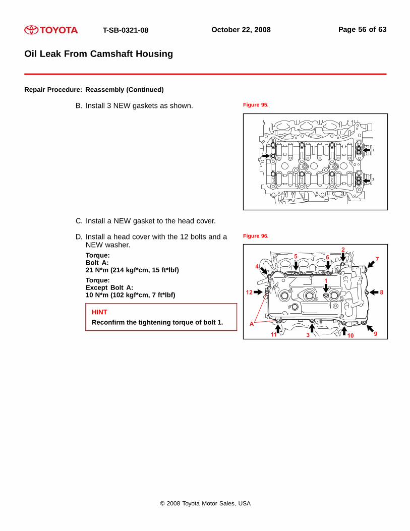
B. Install 3 NEW gaskets as shown. Figure 95.
C. Install a NEW gasket to the head cover.
D. Install a head cover with the 12 bolts and aNEW washer.Torque:Bolt A:21 N*m (214 kgf*cm, 15 ft*lbf)Torque:Except Bolt A:10 N*m (102 kgf*cm, 7 ft*lbf)
HINTReconfirm the tightening torque of bolt 1.
Figure 96.
A
1
4
3 9
8
7
265
12
11 10
© 2008 Toyota Motor Sales, USA
T-SB-0321-08 October 22, 2008 Page 57 of 63
Oil Leak From Camshaft Housing
Repair Procedure: Reassembly (Continued)
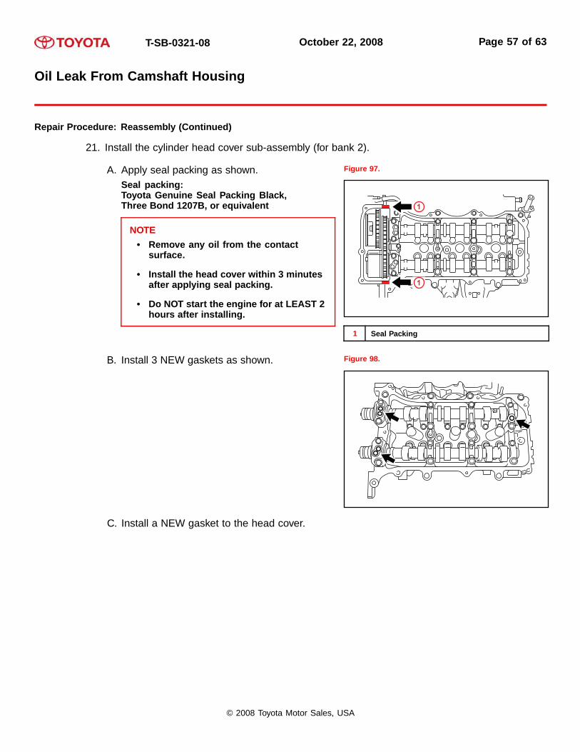
21. Install the cylinder head cover sub-assembly (for bank 2).
A. Apply seal packing as shown.Seal packing:Toyota Genuine Seal Packing Black,Three Bond 1207B, or equivalent
NOTE• Remove any oil from the contact
surface.
• Install the head cover within 3 minutesafter applying seal packing.
• Do NOT start the engine for at LEAST 2hours after installing.
Figure 97.
1
1
1 Seal Packing
B. Install 3 NEW gaskets as shown. Figure 98.
C. Install a NEW gasket to the head cover.
© 2008 Toyota Motor Sales, USA

T-SB-0321-08 October 22, 2008 Page 58 of 63
Oil Leak From Camshaft Housing
Repair Procedure: Reassembly (Continued)
D. Install the head cover with the 12 bolts and aNEW washer.Torque:Bolt A:21 N*m (214 kgf*cm, 15 ft*lbf)Torque:Except Bolt A:10 N*m (102 kgf*cm, 7 ft*lbf)
HINTReconfirm the tightening torque of bolts 1and 10.
Figure 99.
22. Install a new gasket to the No. 1 oil pan (with oilcooler).
Install the No. 1 oil cooler bracket with the oilcooler pipe with the 3 bolts and 3 nuts.Torque: 21 N*m (214 kgf*cm, 15 ft*lbf)
Figure 100.
23. Install the oil cooler assembly (with oil cooler).
A. Install a new O-ring.
B. Install the oil cooler assembly with the unionbolt.Torque: 68 N*m (693 kgf*cm, 50 ft*lbf)
Figure 101.
© 2008 Toyota Motor Sales, USA

T-SB-0321-08 October 22, 2008 Page 59 of 63
Oil Leak From Camshaft Housing
Repair Procedure: Reassembly (Continued)
C. Install the 2 water by-pass hoses with the bolt,2 clamps, and 4 clips.Torque: 10 N*m (102 kgf*cm, 7 ft*lbf)
Figure 102.
24. Install the crankshaft pulley.
A. Align the pulley set key with the key groove of the pulley, and slide on the pulley.
B. Using the SST, install the pulley bolt.SST P/N: 09213-70011 (09213-70020),09330-00021Torque: 250 N*m (2550 kgf*cm, 184 ft*lbf)
Figure 103.
1
2
3
4
1 Hold
2 Turn
3 SST
4 SST
© 2008 Toyota Motor Sales, USA

T-SB-0321-08 October 22, 2008 Page 60 of 63
Oil Leak From Camshaft Housing
Repair Procedure: Reassembly (Continued)
25. Install the oil filter element.
A. Clean the inside of the oil filter cap, thethreads, and O-ring groove.
Figure 104.
2
1
1 Oil Filter Element
2 O-ring
B. Apply a light coat of engine oil to a NEW O-ring and install it to the oil filter cap (P/N90301-79006).
C. Set a NEW oil filter element to the oil filter cap.
D. Remove dirt or foreign matter from the installation surface of the engine.
E. Apply a light coat of engine oil to the O-ring again and install the oil filter cap.
NOTE• Be careful that the O-ring does NOT get caught between the parts.
• The O-ring must NOT be twisted on the groove.
© 2008 Toyota Motor Sales, USA

T-SB-0321-08 October 22, 2008 Page 61 of 63
Oil Leak From Camshaft Housing
Repair Procedure: Reassembly (Continued)
F. Using the SST, tighten the oil filter cap.SST P/N: 09228-06501Torque: 25 N*m (255 kgf*cm, 18 ft*lbf)
NOTEMake sure that the oil filter is installedsecurely as shown.
Figure 105.
1
2
1 No Clearance
2 SST
G. Apply a light coat of engine oil to a NEWO-ring and install it to the oil filter cap (P/N96723-35028).
NOTERemove all dirt and foreign matter from theinstallation surface.
Figure 106.
1
1 O-ring
H. Install the oil filter drain plug to the oil filter cap.Torque: 13 N*m (130 kgf*cm, 9 ft*lbf)
NOTEMake sure that the O-ring does NOT get caught between the parts.
© 2008 Toyota Motor Sales, USA
T-SB-0321-08 October 22, 2008 Page 62 of 63
Oil Leak From Camshaft Housing
Repair Procedure: Reassembly (Continued)
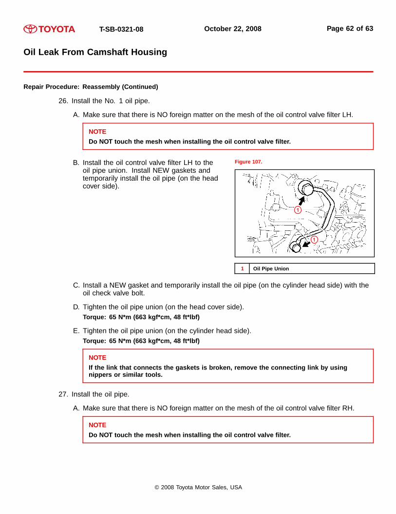
26. Install the No. 1 oil pipe.
A. Make sure that there is NO foreign matter on the mesh of the oil control valve filter LH.
NOTEDo NOT touch the mesh when installing the oil control valve filter.
B. Install the oil control valve filter LH to theoil pipe union. Install NEW gaskets andtemporarily install the oil pipe (on the headcover side).
Figure 107.
1
1
1 Oil Pipe Union
C. Install a NEW gasket and temporarily install the oil pipe (on the cylinder head side) with theoil check valve bolt.
D. Tighten the oil pipe union (on the head cover side).Torque: 65 N*m (663 kgf*cm, 48 ft*lbf)
E. Tighten the oil pipe union (on the cylinder head side).Torque: 65 N*m (663 kgf*cm, 48 ft*lbf)
NOTEIf the link that connects the gaskets is broken, remove the connecting link by usingnippers or similar tools.
27. Install the oil pipe.
A. Make sure that there is NO foreign matter on the mesh of the oil control valve filter RH.
NOTEDo NOT touch the mesh when installing the oil control valve filter.
© 2008 Toyota Motor Sales, USA
T-SB-0321-08 October 22, 2008 Page 63 of 63
Oil Leak From Camshaft Housing
Repair Procedure: Reassembly (Continued)
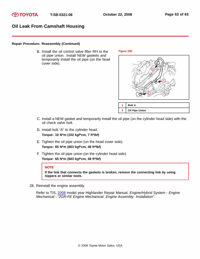
B. Install the oil control valve filter RH to theoil pipe union. Install NEW gaskets andtemporarily install the oil pipe (on the headcover side).
Figure 108.
2
2
1
1 Bolt A
2 Oil Pipe Union
C. Install a NEW gasket and temporarily install the oil pipe (on the cylinder head side) with theoil check valve bolt.
D. Install bolt “A” to the cylinder head.Torque: 10 N*m (102 kgf*cm, 7 ft*lbf)
E. Tighten the oil pipe union (on the head cover side).Torque: 65 N*m (663 kgf*cm, 48 ft*lbf)
F. Tighten the oil pipe union (on the cylinder head side).Torque: 65 N*m (663 kgf*cm, 48 ft*lbf)
NOTEIf the link that connects the gaskets is broken, remove the connecting link by usingnippers or similar tools.
28. Reinstall the engine assembly.
Refer to TIS, 2008 model year Highlander Repair Manual, Engine/Hybrid System - EngineMechanical - “2GR-FE Engine Mechanical: Engine Assembly: Installation”.
© 2008 Toyota Motor Sales, USA