oil separators - bitzer
TRANSCRIPT
Primär-Ölabscheider• Standard-Baureihe
• A-Baureihe für NH3
Sekundär-Ölabscheider• OAS-Baureihe für NH3
Primary oil separators• Standard Series
• A Series for NH3
Secondary oil separators• OAS Series for for NH3
Séparateurs primaires• Série standard
• Série A pour NH3
Séparateurs secondaires• Série OAS pour NH3
OIL SEPARATORSÖLABSCHEIDER
SÉPARATEURS D'HUILE DP-500-2
OIL SEPARATORSÖLABSCHEIDERSÉPARATEURS D'HUILE
Primär-Ölabscheider• Standard-Baureihe
• A-BaureihefürNH3
Sekundär-Ölabscheider• OAS-BaureihefürNH3
Primaryoilseparators• StandardSeries
• ASeriesforNH3
Secondaryoilseparators• OASSeriesforforNH3
Первичные маслоотделители• Стандартная серия
• Серия для NH3
Вторичные маслоотделители• OAS серия для NH3
МАСЛООТДЕЛИТЕЛИ DP-500-2 RUS

2 DP-500-2 RUSST-130-22
2 Functions
The OLC-D1-S can monitor either theminimum or the maximum oil level,depending on its mounting positionand incorporation into the safetychain. If the minimum and the maxi-mum oil level should be monitored,two OLC-D1-S devices must beinstalled.
2.1 Monitoring of the minimumlevel
Lock out
The compressor is shut off, if theprism sticks out of the oil longer thanthe delay time specified by the circuit.
The OLC-D1-S then opens the outputcontact and the circuit locks out elec-tronically: The control voltage to thecompressor contactor is interrupted.The red LED at the face side of theopto-electronic unit lights up (figure 1)as well as the signal lamp H4.
Reset
The circuit can be manually reset bypressing the reset button. This resetbutton (S4) has to be mounted intothe swich board. (Connection seesche matic wiring diagram.)
2 Fonctionnement
Le OLC-D1-S peut contrôler soit leniveau d'huile minimal soit le niveaud'huile maximal, dépendant de la positionde montage et de l'intégration dans lachaîne de sécurité. Pour surveiller leniveau d'huile minimal et maximal enmême temps, deux OLC-D1-S doiventêtre installés.
2.1 Contrôle du niveau d'huile minimal
Verrouiller
Le compresseur est arrêté des lors que letemps pendant lequel le cône de verredépasse le niveau d'huile est supérieur àla la temporisation prédéfinie par leréglage.
Le OLC-D1-S ouvre alors le contact desortie et le circuit se verrouille électroni-quement: la tension de commande ducon tacteur du compresseur est alorscoupée. La LED rouge sur le côté frontalde l'unité opto-électronique s'allume (figu-re 1) et ainsi que la lampe H4.
Déverrouiller
Le circuit peut être remis manuellementen fonctionnement par la touche de reset.Cette touche (S4) devra être montéedans l'armoire électrique. (Raccordementvoir schéma de principe.)
2 Funktionen
Das OLC-D1-S kann entweder dasmini male oder das maximale Ölnive auüber wachen, je nach Montage-Posi ti -on und Einbettung in die Sicher heits -kette. Falls sowohl das mini male wiedas maximale Ölnive au über wachtwerden soll, müssen zwei OLC-D1-Sinstalliert werden.
2.1 Minimale Ölniveau-Überwa-chung
Verriegeln
Der Verdichter wird abgeschaltet,wenn der Glas-Kegel länger als diedurch die Schaltung vorgegebene Ver -zöge rungs zeit aus dem Öl herausragt.
Das OLC-D1-S öffnet dann den Aus -gangs kon takt und die Schaltung ver-riegelt elektronisch: Die Steuerspan -nung zum Verdich ter schütz wird unter-brochen. Die rote LED auf der Stirn -seite der opto-elektronischen Ein heit(Abb. 1) und die Signallampe H4leuchten.
Entriegeln
Die Schaltung kann über eine Reset-Taste manuell zurück gesetzt werden.Diese Reset-Taste (S4) muss imSchalt schrank montiert werden.(Anschluss siehe Prinzipschaltbild.)
Abb. 1 Abmessungen und Aufbau Fig. 1 Dimensions and design
�
� � �
�
�
�
�
� � � � � � � � � � � � � � � � � � �
�
Fig. 1 Dimensions et construction
1 Prisma-Einheit2 Glas-Kegel3 Dichtung4 Opto-elektronische Einheit "OLC-D1"
(360° drehbar)5 Anschlusskabel6 Schraubkappe
1 Prism unit2 Glass cone3 Gasket4 Opto-electronic unit "OLC-D1"
(360° revolving)5 Connecting cable6 Screwing cap
1 Unité prisme2 Cône en verre3 Joint4 Composant opto-électronique "OLC-D1"
(mobile sur 360°)5 Câble de raccordement6 Chapeau à visser
Ölabscheider
Inhalt
1 Ölabscheider für HFKW-Kältemittel und R22 4
2 Ölabscheider für NH3 7
2.1 Primär-Abscheider 7
2.2 OAS-Baureihe 10
Oilseparators
Contents
1 Oil separators for HFC refrigerants and R22 4
2 Oil separators for NH3 7
2.1 Primary separators 7
2.2 OAS Series 10
Маслоотделители
Содержание
1 Маслоотделителидля HFCхладагентовиR22 4
2 МаслоотделителидляNH3 7
2.1 Первичныемаслоотделители 7
2.2 OASсерия 10
DiebesonderenMerkmale
• MinimaleÖlwurfratendurchhoheEffizienz
• AttraktivesPreis-Leistungs-Verhältnis: KombinationausPrimär-Sekundär-Abscheider zum Einsatz in über -fluteten Systemen
• HoheZuverlässigkeit: entwickeltvomMarktfüherderSchraubenverdichter-Technologie
Primär-ÖlabscheiderOA-Baureihe
Standard-Baureihe
Diese Ölabscheider sind für den EinsatzinKältekreisläufenmitallenHFKW-Kältemitteln und R22 geeignet.
A-BaureihefürdenEinsatzmitNH3
AusführungundMaterialiendieserBaureihewurdenspeziellaufdenEinsatz in NH3-Anlagen abgestimmt.
OAS-Baureihe
• Sekundär-ÖlabscheiderfürSchraubenverdichter
• FilterabscheiderfürKolbenverdichter
Diese Feinabscheider mit internem FilterelementundSchwimmerventilsind ebenfalls speziell auf den Einsatz in NH3-Anlagen abgestimmt.
Thespecialfeatures
• Minimumoilcarryoverrateduetohigh efficiency
• Attractivecost-performance-ratio: Combination of primary and secondary separator for the applicationin flooded systems
• Highreliability: developedbythemarketleaderofscrewcompressortechnology
PrimaryoilseparatorsOASeries
Standardseries
Theseoilseparatorsaresuitableforthe application in refrigerant circuits withtheallHFC-refrigerantsandR22.
ASeriesfordenEinsatzwithNH3
Design and material of this series havebeenadaptedespeciallyfortheapplication in NH3 systems.
OASSeries
• Secondaryoilseparatorsforscrewcompressors
• Filterseparatorsforreciprocatingcompressors
Thesefineseparatorswithintegratedfilterelementandfloatvalvehavebeen adapted especially for the appli-cation in NH3systemsaswell.
Отличительные особенности
• Минимальныйкоэффициентуносамаслаблагодарявысокойэффективности
• Привлекательноесоотношениеценыикачества: Комбинацияпервичногоивторичногоотделителядляприменениявзатопленныхсистемах
• Высокаянадежность: разработанымировымлидеромввинтовыхкомпрессорныхтехнологиях
Первичные маслоотделители OA серии
Стандартная серия
ЭтимаслоотделителипригодныдляприменениявхолодильномконтуресHFCхладагентамииR22.
A cерия для применения с NH3
КонструкцияиматериалэтойсерииспециальноадаптированыдляприменениявNH3системах.
OAS серия
• Вторичныемаслоотделителидлявинтовыхкомпрессоров
• Фильтротделителидляпоршневыхкомпрессоров
ЭтиотделителитонкойочисткисинтегрированнымфильтрующимэлементомипоплавковымклапаномбылиспециальноадаптированыдляприменениятакжеивNH3системах.
3DP-500-2 RUSST-130-2 3
2.2 Maximale Ölniveau-Überwa-chung
Elektrischer An schluss und Einbin -dung in die Steue rungs logik sind vonder Konzeption der jeweiligen Anlageabhängig.
So kann beispielsweise bei einerAnlagenkonzeption mit überflutetemVerdampfer ein Magnetventil in derÖlleitung je nach Ölniveau im Verdich -ter angesteuert werden. Ebenso istdie Regelung einer Ölumspeisung imParallelver bund möglich.
2.3 Technische Daten
2.2 Monitoring of the maximumlevel
The electrical connection and its inte-gration into the control logic dependon the design of the particular system.
Thus, for example, in an installationwith flooded evaporator, a solenoidvalve in the oil line can be activated,depending on the oil level in the com-pressor. Likewise, the oil circulationcan also be controlled in parallel.
2.3 Technical data
2.2 Contrôle du niveau d'huile maxi-mal
Le raccordement électrique et l'incorpora-tion à la logique de commande dépen-dent de la conception de l'installation enquestion.
Il est ainsi possible, par exemple dans lecas d'une conception d'installation avecévaporateur noyé, de commander unevanne magnétique dans la conduite d'hui-le, suivant le niveau d'huile dans le com-presseur. La régulation d'un transfertd'huile dans des compresseurs enparallèle est également possible.
2.3 Données tech ni ques
Anschluss-Spannung Supply volt age Tension d'alimentation 230 V AC ± 10% �
Netzfrequenz Supply frequency Fréquence du réseau 50 / 60 Hz
Verzögerungszeit (integriert) Delay time (integrated) Temporisation (integré) 5 s ± 2 s
Vorsicherung für Gerät Fusing for device and Fusible pour appareil etund Schaltkontakte switch contacts contacts de commutation
Maximal zulässiger Druck Maximum allowable pressure Pression maximale admissible
Anschlusskabel Connecting cable Câble de raccordement
Kältemaschinenöle Refrigeration compressor oil Huiles pour machines frigorifiques alle / all / toutes
Kältemittel Refrigerants Fluides frigorigènes
Schutzart (montiert) Enclosure class (mounted) Classe de protection (monté) IP54
Zulässige Umgebungstemperatur Allowable ambient temperature Température ambiante admissible -30 .. +60°C
Gewicht Weight Poids 390 g
� Opto-elektronische Einheit wird alsOLC-D1 ausgeliefert (siehe Seite 2,Abbildung 1, Position 4)
� andere Spannungen auf Anfrage,auch mit UL-Abnahme erhältlich
� Kabel sind farbkodiert
� Opto-electronic unit is delivered asOLC-D1 (see page 2, figure 1, pos. 4)
� other voltages upon request, alsoavailable with UL approval
� Cables are color coded
� Le composant opto-électronique est livréecomme OLC-D1 (voir page 2, figure 1,position 4)
� d'autres types de tension sur demande,aussi avec contrôle UL
� Câbles avec code couleur
5 x AWG 20 (0,75 mm2)L = 2 m �
HFKW, (H)FCKWHFC, (H)CFC
Relais-Ausgänge: Relay output: Sorties de relais:Schaltspannung Switching voltage Tension de commutation max. 240 V ACSchaltstrom Switching current Intensité de commutation max. 2,5 ASchaltleistung Switching capacity Puissance de commutation max. 300 VA
max. 4 A
Maximale Öltemperatur Maximum oil temperature Température d'huile maximale 120°C
33 bar (-20°C .. -10°C) 45 bar (-10°C .. 120°C)
Geräte-Typ Device type Type de dispositif OLC-D1-S �
DietechnischenMerkmale
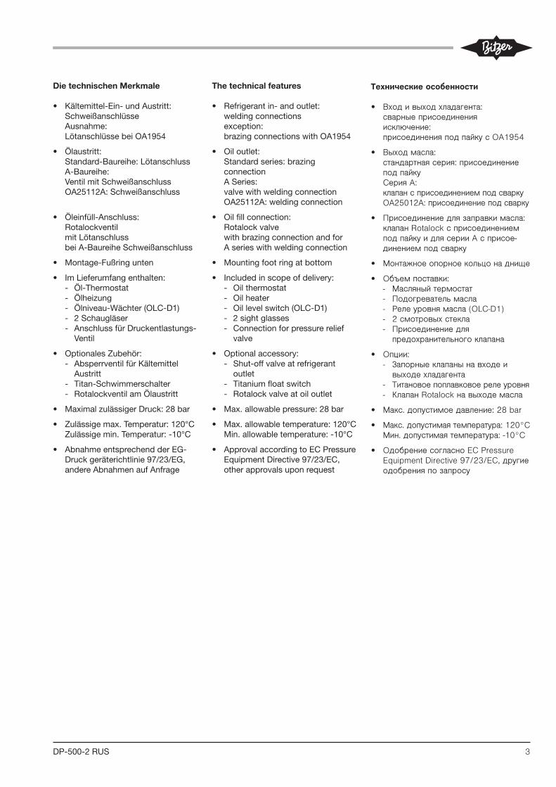
• Kältemittel-Ein-undAustritt: Schweißanschlüsse Ausnahme: LötanschlüssebeiOA1954
• Ölaustritt: Standard-Baureihe:Lötanschluss A-Baureihe: VentilmitSchweißanschlussOA25112A:Schweißanschluss
• Öleinfüll-Anschluss: Rotalockventil mitLötanschluss beiA-BaureiheSchweißanschluss
• Montage-Fußringunten
• ImLieferumfangenthalten:- Öl-Thermostat - Ölheizung- Ölniveau-Wächter(OLC-D1) - 2 Schaugläser- AnschlussfürDruckentlastungs-
Ventil
• OptionalesZubehör:- AbsperrventilfürKältemittel
Austritt- Titan-Schwimmerschalter- RotalockventilamÖlaustritt
• MaximalzulässigerDruck:28bar
• Zulässigemax.Temperatur:120°C Zulässigemin.Temperatur:-10°C
• AbnahmeentsprechendderEG-Druckgeräterichtlinie97/23/EG,andere Abnahmen auf Anfrage
Thetechnicalfeatures
• Refrigerantin-andoutlet: weldingconnections exception: brazingconnectionswithOA1954
• Oiloutlet: Standard series: brazing connection A Series: valvewithweldingconnectionOA25112A:weldingconnection
• Oilfillconnection: Rotalockvalve withbrazingconnectionandforAserieswithweldingconnection
• Mountingfootringatbottom
• Includedinscopeofdelivery: - Oil thermostat - Oil heater- Oillevelswitch(OLC-D1) - 2 sight glasses - Connection for pressure relief
valve
• Optionalaccessory:- Shut-offvalveatrefrigerant
outlet- Titaniumfloatswitch- Rotalockvalveatoiloutlet
• Max.allowablepressure:28bar
• Max.allowabletemperature:120°C Min.allowabletemperature:-10°C
• ApprovalaccordingtoECPressureEquipmentDirective97/23/EC,otherapprovalsuponrequest
Технические особенности
• Входивыходхладагента: сварныеприсоединения исключение: присоединенияподпайкусOA1954
• Выходмасла: стандартнаясерия:присоединениеподпайку СерияA: клапансприсоединениемподсваркуOA25012A:присоединениеподсварку
• Присоединениедлязаправкимасла: клапанRotalockсприсоединениемподпайкуидлясерииAсприсоединениемподсварку
• Монтажноеопорноекольцонаднище
• Объемпоставки: Масляныйтермостат Подогревательмасла Релеуровнямасла(OLCD1) 2смотровыхстекла Присоединениедля
предохранительногоклапана
• Опции: Запорныеклапанынавходеи
выходехладагента Титановоепоплавковоерелеуровня КлапанRotalockнавыходемасла
• Макс.допустимоедавление:28bar
• Макс.допустимаятемпература:120°С Мин.допустимаятемпература:10°С
• ОдобрениесогласноECPressureEquipmentDirective97/23/EC,другиеодобренияпозапросу

4 DP-500-2 RUSST-130-22
2 Functions
The OLC-D1-S can monitor either theminimum or the maximum oil level,depending on its mounting positionand incorporation into the safetychain. If the minimum and the maxi-mum oil level should be monitored,two OLC-D1-S devices must beinstalled.
2.1 Monitoring of the minimumlevel
Lock out
The compressor is shut off, if theprism sticks out of the oil longer thanthe delay time specified by the circuit.
The OLC-D1-S then opens the outputcontact and the circuit locks out elec-tronically: The control voltage to thecompressor contactor is interrupted.The red LED at the face side of theopto-electronic unit lights up (figure 1)as well as the signal lamp H4.
Reset
The circuit can be manually reset bypressing the reset button. This resetbutton (S4) has to be mounted intothe swich board. (Connection seesche matic wiring diagram.)
2 Fonctionnement
Le OLC-D1-S peut contrôler soit leniveau d'huile minimal soit le niveaud'huile maximal, dépendant de la positionde montage et de l'intégration dans lachaîne de sécurité. Pour surveiller leniveau d'huile minimal et maximal enmême temps, deux OLC-D1-S doiventêtre installés.
2.1 Contrôle du niveau d'huile minimal
Verrouiller
Le compresseur est arrêté des lors que letemps pendant lequel le cône de verredépasse le niveau d'huile est supérieur àla la temporisation prédéfinie par leréglage.
Le OLC-D1-S ouvre alors le contact desortie et le circuit se verrouille électroni-quement: la tension de commande ducon tacteur du compresseur est alorscoupée. La LED rouge sur le côté frontalde l'unité opto-électronique s'allume (figu-re 1) et ainsi que la lampe H4.
Déverrouiller
Le circuit peut être remis manuellementen fonctionnement par la touche de reset.Cette touche (S4) devra être montéedans l'armoire électrique. (Raccordementvoir schéma de principe.)
2 Funktionen
Das OLC-D1-S kann entweder dasmini male oder das maximale Ölnive auüber wachen, je nach Montage-Posi ti -on und Einbettung in die Sicher heits -kette. Falls sowohl das mini male wiedas maximale Ölnive au über wachtwerden soll, müssen zwei OLC-D1-Sinstalliert werden.
2.1 Minimale Ölniveau-Überwa-chung
Verriegeln
Der Verdichter wird abgeschaltet,wenn der Glas-Kegel länger als diedurch die Schaltung vorgegebene Ver -zöge rungs zeit aus dem Öl herausragt.
Das OLC-D1-S öffnet dann den Aus -gangs kon takt und die Schaltung ver-riegelt elektronisch: Die Steuerspan -nung zum Verdich ter schütz wird unter-brochen. Die rote LED auf der Stirn -seite der opto-elektronischen Ein heit(Abb. 1) und die Signallampe H4leuchten.
Entriegeln
Die Schaltung kann über eine Reset-Taste manuell zurück gesetzt werden.Diese Reset-Taste (S4) muss imSchalt schrank montiert werden.(Anschluss siehe Prinzipschaltbild.)
Abb. 1 Abmessungen und Aufbau Fig. 1 Dimensions and design
�
� � �
�
�
�
�
� � � � � � � � � � � � � � � � � � �
�
Fig. 1 Dimensions et construction
1 Prisma-Einheit2 Glas-Kegel3 Dichtung4 Opto-elektronische Einheit "OLC-D1"
(360° drehbar)5 Anschlusskabel6 Schraubkappe
1 Prism unit2 Glass cone3 Gasket4 Opto-electronic unit "OLC-D1"
(360° revolving)5 Connecting cable6 Screwing cap
1 Unité prisme2 Cône en verre3 Joint4 Composant opto-électronique "OLC-D1"
(mobile sur 360°)5 Câble de raccordement6 Chapeau à visser
ST-130-2 3
2.2 Maximale Ölniveau-Überwa-chung
Elektrischer An schluss und Einbin -dung in die Steue rungs logik sind vonder Konzeption der jeweiligen Anlageabhängig.
So kann beispielsweise bei einerAnlagenkonzeption mit überflutetemVerdampfer ein Magnetventil in derÖlleitung je nach Ölniveau im Verdich -ter angesteuert werden. Ebenso istdie Regelung einer Ölumspeisung imParallelver bund möglich.
2.3 Technische Daten
2.2 Monitoring of the maximumlevel
The electrical connection and its inte-gration into the control logic dependon the design of the particular system.
Thus, for example, in an installationwith flooded evaporator, a solenoidvalve in the oil line can be activated,depending on the oil level in the com-pressor. Likewise, the oil circulationcan also be controlled in parallel.
2.3 Technical data
2.2 Contrôle du niveau d'huile maxi-mal
Le raccordement électrique et l'incorpora-tion à la logique de commande dépen-dent de la conception de l'installation enquestion.
Il est ainsi possible, par exemple dans lecas d'une conception d'installation avecévaporateur noyé, de commander unevanne magnétique dans la conduite d'hui-le, suivant le niveau d'huile dans le com-presseur. La régulation d'un transfertd'huile dans des compresseurs enparallèle est également possible.
2.3 Données tech ni ques
Anschluss-Spannung Supply volt age Tension d'alimentation 230 V AC ± 10% �
Netzfrequenz Supply frequency Fréquence du réseau 50 / 60 Hz
Verzögerungszeit (integriert) Delay time (integrated) Temporisation (integré) 5 s ± 2 s
Vorsicherung für Gerät Fusing for device and Fusible pour appareil etund Schaltkontakte switch contacts contacts de commutation
Maximal zulässiger Druck Maximum allowable pressure Pression maximale admissible
Anschlusskabel Connecting cable Câble de raccordement
Kältemaschinenöle Refrigeration compressor oil Huiles pour machines frigorifiques alle / all / toutes
Kältemittel Refrigerants Fluides frigorigènes
Schutzart (montiert) Enclosure class (mounted) Classe de protection (monté) IP54
Zulässige Umgebungstemperatur Allowable ambient temperature Température ambiante admissible -30 .. +60°C
Gewicht Weight Poids 390 g
� Opto-elektronische Einheit wird alsOLC-D1 ausgeliefert (siehe Seite 2,Abbildung 1, Position 4)
� andere Spannungen auf Anfrage,auch mit UL-Abnahme erhältlich
� Kabel sind farbkodiert
� Opto-electronic unit is delivered asOLC-D1 (see page 2, figure 1, pos. 4)
� other voltages upon request, alsoavailable with UL approval
� Cables are color coded
� Le composant opto-électronique est livréecomme OLC-D1 (voir page 2, figure 1,position 4)
� d'autres types de tension sur demande,aussi avec contrôle UL
� Câbles avec code couleur
5 x AWG 20 (0,75 mm2)L = 2 m �
HFKW, (H)FCKWHFC, (H)CFC
Relais-Ausgänge: Relay output: Sorties de relais:Schaltspannung Switching voltage Tension de commutation max. 240 V ACSchaltstrom Switching current Intensité de commutation max. 2,5 ASchaltleistung Switching capacity Puissance de commutation max. 300 VA
max. 4 A
Maximale Öltemperatur Maximum oil temperature Température d'huile maximale 120°C
33 bar (-20°C .. -10°C) 45 bar (-10°C .. 120°C)
Geräte-Typ Device type Type de dispositif OLC-D1-S �
1 ÖlabscheiderfürHFKW-KältemittelundR22
Anwendungsbereiche
DiefolgendeÜbersichtstabelleermög-lichteineSchnellauswahlvonÖlab-scheidern(bisto=+5°C)aufBasisdesmaximalenSaugvolumenstroms(theoretischesFördervolumen).EineAuswahlunterVorgabederrealenBetriebsbedingungen–einschließlichECO-Anwendung–istmitderBITZERSoftwaremöglich.DieseMethodeberücksichtigtalleEingabe-Parameterundsolltedeshalbbevorzugtwerden.
Auslegung für Systeme mit überflute-tem Verdampfer auf Anfrage.
TechnischeDaten
➀ GewindepassendinvormontierteTauchhülse
1 OilseparatorsforHFCrefrigerantsandR22
Applicationranges
Thefollowingchartallowsaquickselectionofoilseparators(upto to =+5°C)basedonthemaximumsuctionvolumeflow(theoreticaldis-placement).Aselectionbasedonactual operating conditions – including ECO operation – can be made by usingtheBITZERSoftware.Thismethod considers all input parameters andshouldthereforebefavoured.
Layoutforsystemswithfloodedeva-porator upon request.
Technicaldata
➀ Threadfitsinpre-mountedheatersleeve
1 Маслоотделители для HFC хладагентов и R22
Области применения
Следующаятаблицапозволяетосуще ствитьбыстрыйподбормаслоотделителей(доto=+5°C)основанныйнамаксимальнойобъемнойподаче(теоретическойобъемнойпроизводительности).Подбор,основанныйнареальныхрабочихусловиях–включаяработусECO–можетбытьпроизведенспомощьюBITZERSoftware.Этотметодучитываетвсеисходныепараметрыипоэтомуявляетсяприоритетным.
Схемадлясистемсзатопленнымиспарителемпредоставляетсяпозапросу.
Технические данные
➀ Резьбовоеприсоединениевпредварительносмонтированнойгильзеподогревателя
maximalerSaugvolumenstrom(theoretischesFördervolumen)maximumsuctionvolumeflow(theoreticaldisplacement)
максимальная объемная подача (теоретическая объемная производительность)
R134aR22
R404AR507A
R134aR22
R404AR507A HS.53 HS.74 HS.85
OA1954 250 220 300 300 300 max. 2 1
OA4188 580 440 660 620 660 max. 5 2 1
OA9111 1160 840 1320 1180 1320 max. 5 3
OA14111 1320 1180 1320 1320 1320 max. 6 4
OA25112 2050 1900 2300 2100 2500 max. 6 6
KlimabereichHigh temperature range
Высокотемпературнаяобласть
m3/h
Normalkühl-BereichMediumtemperaturerange
Среднетемп.обл
m3/h
Tiefkühl-BereichLowtemperaturerange
Низкотемп.обл
m3/h
Anzahl VerdichterNo. of compressors
Колвокомпрессоров
TypTypeТип
GewichtWeightВес
[kg]
MaximaleÖlfüllungMaxiumumoilchargeМакс заправка маслом
[dm3]
Behälter-Inhalt(gesamt)Receivervolume(total)Объем сосуда (общий)
[dm3]
ÖlheizungOilheaterПодогреватель масла
[Watt] ➀
OA1954 45 18 40 1 x 140
OA4188 95 40 88 2 x 140
OA9111 180 90 228 3 x 140
OA14111 290 140 395 3 x 140
OA25112 565 250 655 3 x 200
5DP-500-2 RUSST-130-2 3
2.2 Maximale Ölniveau-Überwa-chung
Elektrischer An schluss und Einbin -dung in die Steue rungs logik sind vonder Konzeption der jeweiligen Anlageabhängig.
So kann beispielsweise bei einerAnlagenkonzeption mit überflutetemVerdampfer ein Magnetventil in derÖlleitung je nach Ölniveau im Verdich -ter angesteuert werden. Ebenso istdie Regelung einer Ölumspeisung imParallelver bund möglich.
2.3 Technische Daten
2.2 Monitoring of the maximumlevel
The electrical connection and its inte-gration into the control logic dependon the design of the particular system.
Thus, for example, in an installationwith flooded evaporator, a solenoidvalve in the oil line can be activated,depending on the oil level in the com-pressor. Likewise, the oil circulationcan also be controlled in parallel.
2.3 Technical data
2.2 Contrôle du niveau d'huile maxi-mal
Le raccordement électrique et l'incorpora-tion à la logique de commande dépen-dent de la conception de l'installation enquestion.
Il est ainsi possible, par exemple dans lecas d'une conception d'installation avecévaporateur noyé, de commander unevanne magnétique dans la conduite d'hui-le, suivant le niveau d'huile dans le com-presseur. La régulation d'un transfertd'huile dans des compresseurs enparallèle est également possible.
2.3 Données tech ni ques
Anschluss-Spannung Supply volt age Tension d'alimentation 230 V AC ± 10% �
Netzfrequenz Supply frequency Fréquence du réseau 50 / 60 Hz
Verzögerungszeit (integriert) Delay time (integrated) Temporisation (integré) 5 s ± 2 s
Vorsicherung für Gerät Fusing for device and Fusible pour appareil etund Schaltkontakte switch contacts contacts de commutation
Maximal zulässiger Druck Maximum allowable pressure Pression maximale admissible
Anschlusskabel Connecting cable Câble de raccordement
Kältemaschinenöle Refrigeration compressor oil Huiles pour machines frigorifiques alle / all / toutes
Kältemittel Refrigerants Fluides frigorigènes
Schutzart (montiert) Enclosure class (mounted) Classe de protection (monté) IP54
Zulässige Umgebungstemperatur Allowable ambient temperature Température ambiante admissible -30 .. +60°C
Gewicht Weight Poids 390 g
� Opto-elektronische Einheit wird alsOLC-D1 ausgeliefert (siehe Seite 2,Abbildung 1, Position 4)
� andere Spannungen auf Anfrage,auch mit UL-Abnahme erhältlich
� Kabel sind farbkodiert
� Opto-electronic unit is delivered asOLC-D1 (see page 2, figure 1, pos. 4)
� other voltages upon request, alsoavailable with UL approval
� Cables are color coded
� Le composant opto-électronique est livréecomme OLC-D1 (voir page 2, figure 1,position 4)
� d'autres types de tension sur demande,aussi avec contrôle UL
� Câbles avec code couleur
5 x AWG 20 (0,75 mm2)L = 2 m �
HFKW, (H)FCKWHFC, (H)CFC
Relais-Ausgänge: Relay output: Sorties de relais:Schaltspannung Switching voltage Tension de commutation max. 240 V ACSchaltstrom Switching current Intensité de commutation max. 2,5 ASchaltleistung Switching capacity Puissance de commutation max. 300 VA
max. 4 A
Maximale Öltemperatur Maximum oil temperature Température d'huile maximale 120°C
33 bar (-20°C .. -10°C) 45 bar (-10°C .. 120°C)
Geräte-Typ Device type Type de dispositif OLC-D1-S �
5
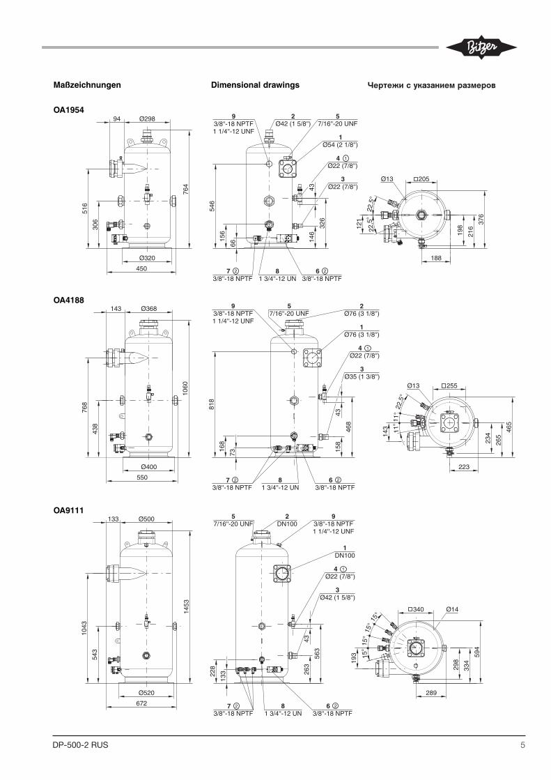
Maßzeichnungen
OA1954
OA4188
OA9111
Dimensional drawings Croquis cotés
DP-500-2
Ø320
Ø29894
516
1 3/4''-12 UN8
306
764
Ø22 (7/8'')
546
66
3/8''-18 NPTF
43
326
146
3/8''-18 NPTF
3
3/8''-18 NPTF1 1/4''-12 UNF
9 27/16''-20 UNF
5
Ø13 205
121
198
216
376
188
22,5
°22
,5°
Ø42 (1 5/8'')
Ø22 (7/8'')
156
450
1Ø54 (2 1/8'')
4 1
7 2 6 2
Ø400
768
1 3/4''-12 UN8
Ø22 (7/8'')
3/8''-18 NPTF 3/8''-18 NPTF
3
3/8''-18 NPTF1 1/4''-12 UNF
9 27/16''-20 UNF
5Ø76 (3 1/8'')
Ø35 (1 3/8'')
438
1060
143 Ø368
550
818
168
73
4315
8
468
1Ø76 (3 1/8'')
Ø13 25511
°22
,5°
11°
23414
3
223
265
465
4 1
7 2 6 2
Ø14
Ø500133
672
1043
543
1453
228
Ø520
133
563
1 3/4''-12 UN8
Ø22 (7/8'')
3/8''-18 NPTF 3/8''-18 NPTF
3
3/8''-18 NPTF1 1/4''-12 UNF
97/16''-20 UNF
5
Ø42 (1 5/8'')
43
193
263
DN1002
DN1001
15°
15°
15°
15°
340
289
298
334
594
4 1
7 2 6 2
Чертежи с указанием размеров
6 DP-500-2 RUSST-130-22
2 Functions
The OLC-D1-S can monitor either theminimum or the maximum oil level,depending on its mounting positionand incorporation into the safetychain. If the minimum and the maxi-mum oil level should be monitored,two OLC-D1-S devices must beinstalled.
2.1 Monitoring of the minimumlevel
Lock out
The compressor is shut off, if theprism sticks out of the oil longer thanthe delay time specified by the circuit.
The OLC-D1-S then opens the outputcontact and the circuit locks out elec-tronically: The control voltage to thecompressor contactor is interrupted.The red LED at the face side of theopto-electronic unit lights up (figure 1)as well as the signal lamp H4.
Reset
The circuit can be manually reset bypressing the reset button. This resetbutton (S4) has to be mounted intothe swich board. (Connection seesche matic wiring diagram.)
2 Fonctionnement
Le OLC-D1-S peut contrôler soit leniveau d'huile minimal soit le niveaud'huile maximal, dépendant de la positionde montage et de l'intégration dans lachaîne de sécurité. Pour surveiller leniveau d'huile minimal et maximal enmême temps, deux OLC-D1-S doiventêtre installés.
2.1 Contrôle du niveau d'huile minimal
Verrouiller
Le compresseur est arrêté des lors que letemps pendant lequel le cône de verredépasse le niveau d'huile est supérieur àla la temporisation prédéfinie par leréglage.
Le OLC-D1-S ouvre alors le contact desortie et le circuit se verrouille électroni-quement: la tension de commande ducon tacteur du compresseur est alorscoupée. La LED rouge sur le côté frontalde l'unité opto-électronique s'allume (figu-re 1) et ainsi que la lampe H4.
Déverrouiller
Le circuit peut être remis manuellementen fonctionnement par la touche de reset.Cette touche (S4) devra être montéedans l'armoire électrique. (Raccordementvoir schéma de principe.)
2 Funktionen
Das OLC-D1-S kann entweder dasmini male oder das maximale Ölnive auüber wachen, je nach Montage-Posi ti -on und Einbettung in die Sicher heits -kette. Falls sowohl das mini male wiedas maximale Ölnive au über wachtwerden soll, müssen zwei OLC-D1-Sinstalliert werden.
2.1 Minimale Ölniveau-Überwa-chung
Verriegeln
Der Verdichter wird abgeschaltet,wenn der Glas-Kegel länger als diedurch die Schaltung vorgegebene Ver -zöge rungs zeit aus dem Öl herausragt.
Das OLC-D1-S öffnet dann den Aus -gangs kon takt und die Schaltung ver-riegelt elektronisch: Die Steuerspan -nung zum Verdich ter schütz wird unter-brochen. Die rote LED auf der Stirn -seite der opto-elektronischen Ein heit(Abb. 1) und die Signallampe H4leuchten.
Entriegeln
Die Schaltung kann über eine Reset-Taste manuell zurück gesetzt werden.Diese Reset-Taste (S4) muss imSchalt schrank montiert werden.(Anschluss siehe Prinzipschaltbild.)
Abb. 1 Abmessungen und Aufbau Fig. 1 Dimensions and design
�
� � �
�
�
�
�
� � � � � � � � � � � � � � � � � � �
�
Fig. 1 Dimensions et construction
1 Prisma-Einheit2 Glas-Kegel3 Dichtung4 Opto-elektronische Einheit "OLC-D1"
(360° drehbar)5 Anschlusskabel6 Schraubkappe
1 Prism unit2 Glass cone3 Gasket4 Opto-electronic unit "OLC-D1"
(360° revolving)5 Connecting cable6 Screwing cap
1 Unité prisme2 Cône en verre3 Joint4 Composant opto-électronique "OLC-D1"
(mobile sur 360°)5 Câble de raccordement6 Chapeau à visser
6
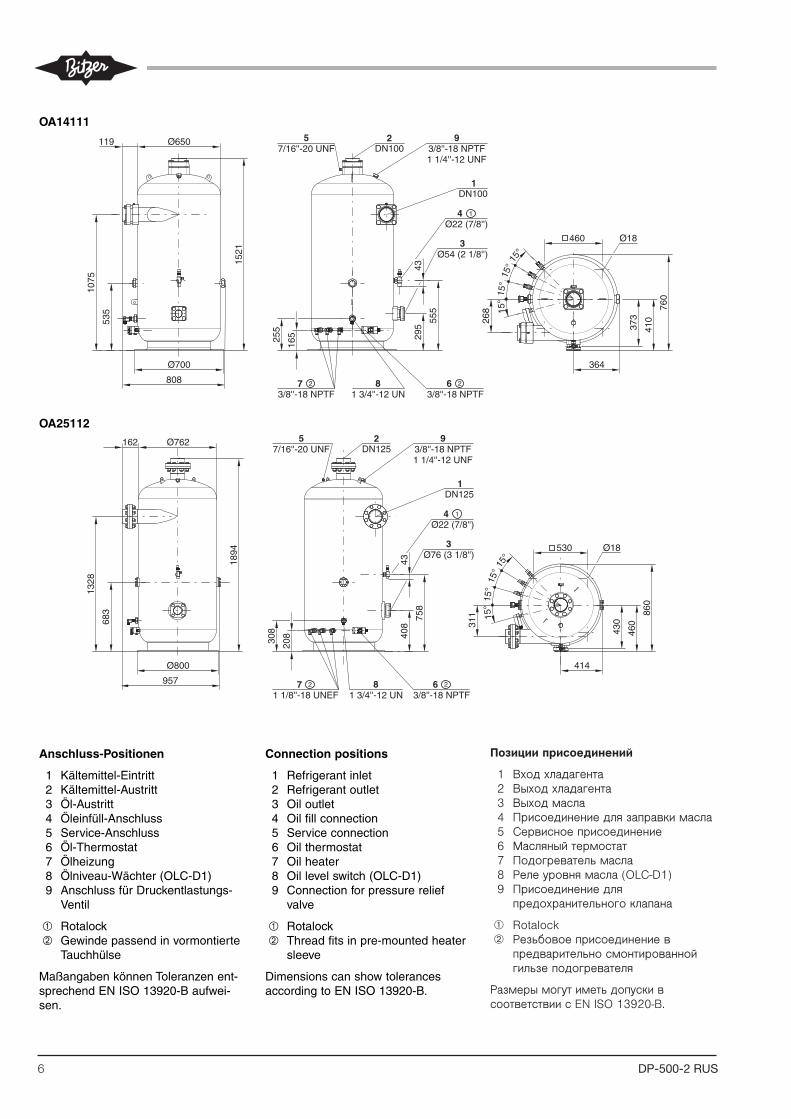
Connection positions
1 Refrigerant inlet2 Refrigerant outlet3 Oil outlet4 Oil fill connection5 Service connection6 Oil thermostat7 Oil heater 8 Oil level switch (OLC-D1)9 Connection for pressure relief
valve
� Rotalock� Thread fits in pre-mounted heater
sleeve
Dimensions can show tolerancesaccording to EN ISO 13920-B.
Position des raccords
1 Entrée de fluide frigorigène2 Sortie de fluide frigorigène3 Sortie d'huile4 Raccord pour le remplissage d'huile5 Raccord pour service6 Thermostat d'huile7 Chauffage d'huile8 Contrôleur de niveau d'huile
(OLC-D1)9 Raccord pour soupape de décharge
� Rotalock� Filetage approprié dans doigt de gant
pré-assemblé
Les dimensions peuvent présenter destolérances conformément à EN ISO13920-B.
OA14111
OA25112
Anschluss-Positionen
1 Kältemittel-Eintritt2 Kältemittel-Austritt3 Öl-Austritt4 Öleinfüll-Anschluss5 Service-Anschluss6 Öl-Thermostat7 Ölheizung8 Ölniveau-Wächter (OLC-D1)9 Anschluss für Druckentlastungs-
Ventil
� Rotalock� Gewinde passend in vormontierte
Tauchhülse
Maßangaben können Toleranzen ent-sprechend EN ISO 13920-B aufwei-sen.
DP-500-2
Ø700
1 3/4''-12 UN8
Ø22 (7/8'')
3/8''-18 NPTF 3/8''-18 NPTF
3
3/8''-18 NPTF1 1/4''-12 UNF
927/16''-20 UNF
5DN100
Ø54 (2 1/8'')
Ø650
1
Ø18460
119
1075
535
1521
4329
5
555
808
255
165
DN100
268 15
°15
°15
°15
°
364
373
410
760
4 1
7 2 6 2
Ø800
1 3/4''-12 UN8
Ø22 (7/8'')
1 1/8''-18 UNEF 3/8''-18 NPTF
3
3/8''-18 NPTF1 1/4''-12 UNF
927/16''-20 UNF
5DN125
Ø76 (3 1/8'')
Ø762
1
Ø18530
43
308
DN125
408 31
1
162
1328
683
1894
957
208
758
15°
15°
15°
15°
430
460
860
414
4 1
7 2 6 2
Позиции присоединений
1 Входхладагента 2 Выходхладагента 3 Выходмасла 4 Присоединениедлязаправкимасла 5 Сервисноеприсоединение 6 Масляныйтермостат 7 Подогревательмасла 8 Релеуровнямасла(OLCD1) 9 Присоединениедля
предохранительногоклапана
➀ Rotalock ➁ Резьбовоеприсоединениев
предварительносмонтированнойгильзеподогревателя
РазмерымогутиметьдопускивсоответствиисENISO13920B.

7DP-500-2 RUSST-130-2 3
2.2 Maximale Ölniveau-Überwa-chung
Elektrischer An schluss und Einbin -dung in die Steue rungs logik sind vonder Konzeption der jeweiligen Anlageabhängig.
So kann beispielsweise bei einerAnlagenkonzeption mit überflutetemVerdampfer ein Magnetventil in derÖlleitung je nach Ölniveau im Verdich -ter angesteuert werden. Ebenso istdie Regelung einer Ölumspeisung imParallelver bund möglich.
2.3 Technische Daten
2.2 Monitoring of the maximumlevel
The electrical connection and its inte-gration into the control logic dependon the design of the particular system.
Thus, for example, in an installationwith flooded evaporator, a solenoidvalve in the oil line can be activated,depending on the oil level in the com-pressor. Likewise, the oil circulationcan also be controlled in parallel.
2.3 Technical data
2.2 Contrôle du niveau d'huile maxi-mal
Le raccordement électrique et l'incorpora-tion à la logique de commande dépen-dent de la conception de l'installation enquestion.
Il est ainsi possible, par exemple dans lecas d'une conception d'installation avecévaporateur noyé, de commander unevanne magnétique dans la conduite d'hui-le, suivant le niveau d'huile dans le com-presseur. La régulation d'un transfertd'huile dans des compresseurs enparallèle est également possible.
2.3 Données tech ni ques
Anschluss-Spannung Supply volt age Tension d'alimentation 230 V AC ± 10% �
Netzfrequenz Supply frequency Fréquence du réseau 50 / 60 Hz
Verzögerungszeit (integriert) Delay time (integrated) Temporisation (integré) 5 s ± 2 s
Vorsicherung für Gerät Fusing for device and Fusible pour appareil etund Schaltkontakte switch contacts contacts de commutation
Maximal zulässiger Druck Maximum allowable pressure Pression maximale admissible
Anschlusskabel Connecting cable Câble de raccordement
Kältemaschinenöle Refrigeration compressor oil Huiles pour machines frigorifiques alle / all / toutes
Kältemittel Refrigerants Fluides frigorigènes
Schutzart (montiert) Enclosure class (mounted) Classe de protection (monté) IP54
Zulässige Umgebungstemperatur Allowable ambient temperature Température ambiante admissible -30 .. +60°C
Gewicht Weight Poids 390 g
� Opto-elektronische Einheit wird alsOLC-D1 ausgeliefert (siehe Seite 2,Abbildung 1, Position 4)
� andere Spannungen auf Anfrage,auch mit UL-Abnahme erhältlich
� Kabel sind farbkodiert
� Opto-electronic unit is delivered asOLC-D1 (see page 2, figure 1, pos. 4)
� other voltages upon request, alsoavailable with UL approval
� Cables are color coded
� Le composant opto-électronique est livréecomme OLC-D1 (voir page 2, figure 1,position 4)
� d'autres types de tension sur demande,aussi avec contrôle UL
� Câbles avec code couleur
5 x AWG 20 (0,75 mm2)L = 2 m �
HFKW, (H)FCKWHFC, (H)CFC
Relais-Ausgänge: Relay output: Sorties de relais:Schaltspannung Switching voltage Tension de commutation max. 240 V ACSchaltstrom Switching current Intensité de commutation max. 2,5 ASchaltleistung Switching capacity Puissance de commutation max. 300 VA
max. 4 A
Maximale Öltemperatur Maximum oil temperature Température d'huile maximale 120°C
33 bar (-20°C .. -10°C) 45 bar (-10°C .. 120°C)
Geräte-Typ Device type Type de dispositif OLC-D1-S �
2 ÖlabscheiderfürNH3
2.1 Primär-Abscheider
Anwendungsbereiche
SchnellauswahlvonPrimär-Abschei-dern(bisto =+5°C)aufBasisdesmaximalenSaugvolumenstromssieheÜbersichtstabelle.AuswahlunterVor-gabe der realen Betriebsbedingungen –einschließlichECO-Anwendung–istmitderBITZERSoftwaremöglich.DieseMethodeberücksichtigtalleEin-gabe-Parameter und sollte deshalb bevorzugtwerden.
OAS-Abscheider siehe Kapitel 2.2.
TechnischeDaten
➀ GewindepassendinvormontierteTauchhülse
2 OilseparatorsforNH3
2.1 Primaryseparators
Applicationranges
Thefollowingchartallowsaquickselectionofprimaryseparators(uptoto =+5°C)basedonthemaximumsuctionvolumeflow.Aselectionbased on actual operating conditions – including ECO operation – can be madebyusingtheBITZERSoftware.Thismethodconsidersallinputpara- meters and should therefore be favoured.
OAS separators see chapter 2.2.
Technicaldata
➀ Threadfitsinpre-mountedheatersleeve
2 Маслоотделители для NH3
2.1 Первичные маслоотделители
Области применения
Следующаятаблицапозволяетосуществитьбыстрыйподбормаслоотделителей(доto=+5°C)основанныйнамаксимальнойобъемнойподаче.Подбор,основанныйнареальныхрабочихусловиях–включаяработусECO–можетбытьпроизведенспомощьюBITZERSoftware.Этотметодучитываетвсеисходныепараметрыипоэтомуявляетсяприоритетным.
МаслоотделителиOASсм.вглаве2.2
Технические данные
➀ Резьбовоеприсоединениевпредварительносмонтированнойгильзеподогревателя
maximalerSaugvolumenstrom(theoretischesFördervolumen)maximumsuctionvolumeflow(theoreticaldisplacement)
максимальная объемная подача (теоретическая объемная производительность)
m3/h m3/h m3/h OS.A53 OS.A74 OS8553
OA1954A 160 230 300 max. 1 1
OA4188A 320 440 660 max. 3 2 1
OA9111A 640 900 1320 max. 6 4 2
OA14111A 960 1320 1320 max. 6 3
OA25112A 1460 2050 2500 max. 6 5
KlimabereichHigh temperature range
Высокотемпературнаяобласть
Normalkühl-BereichMediumtemperaturerange
Среднетемп.обл
Tiefkühl-BereichLowtemperaturerange
Низкотемп.обл
Anzahl VerdichterNo. of compressors
Колвокомпрессоров
TypTypeТип
GewichtWeightВес
[kg]
MaximaleÖlfüllungMaxiumumoilchargeМакс заправка маслом
[dm3]
Behälter-Inhalt(gesamt)Receivervolume(total)Объем сосуда (общий)
[dm3]
ÖlheizungOilheaterПодогреватель масла
[Watt] ➀
OA1954A 50 18 40 1 x 140
OA4188A 95 40 88 2 x 140
OA9111A 185 90 228 3 x 140
OA14111A 295 140 395 3 x 140
OA25112A 565 250 655 3 x 200
8 DP-500-2 RUSST-130-22
2 Functions
The OLC-D1-S can monitor either theminimum or the maximum oil level,depending on its mounting positionand incorporation into the safetychain. If the minimum and the maxi-mum oil level should be monitored,two OLC-D1-S devices must beinstalled.
2.1 Monitoring of the minimumlevel
Lock out
The compressor is shut off, if theprism sticks out of the oil longer thanthe delay time specified by the circuit.
The OLC-D1-S then opens the outputcontact and the circuit locks out elec-tronically: The control voltage to thecompressor contactor is interrupted.The red LED at the face side of theopto-electronic unit lights up (figure 1)as well as the signal lamp H4.
Reset
The circuit can be manually reset bypressing the reset button. This resetbutton (S4) has to be mounted intothe swich board. (Connection seesche matic wiring diagram.)
2 Fonctionnement
Le OLC-D1-S peut contrôler soit leniveau d'huile minimal soit le niveaud'huile maximal, dépendant de la positionde montage et de l'intégration dans lachaîne de sécurité. Pour surveiller leniveau d'huile minimal et maximal enmême temps, deux OLC-D1-S doiventêtre installés.
2.1 Contrôle du niveau d'huile minimal
Verrouiller
Le compresseur est arrêté des lors que letemps pendant lequel le cône de verredépasse le niveau d'huile est supérieur àla la temporisation prédéfinie par leréglage.
Le OLC-D1-S ouvre alors le contact desortie et le circuit se verrouille électroni-quement: la tension de commande ducon tacteur du compresseur est alorscoupée. La LED rouge sur le côté frontalde l'unité opto-électronique s'allume (figu-re 1) et ainsi que la lampe H4.
Déverrouiller
Le circuit peut être remis manuellementen fonctionnement par la touche de reset.Cette touche (S4) devra être montéedans l'armoire électrique. (Raccordementvoir schéma de principe.)
2 Funktionen
Das OLC-D1-S kann entweder dasmini male oder das maximale Ölnive auüber wachen, je nach Montage-Posi ti -on und Einbettung in die Sicher heits -kette. Falls sowohl das mini male wiedas maximale Ölnive au über wachtwerden soll, müssen zwei OLC-D1-Sinstalliert werden.
2.1 Minimale Ölniveau-Überwa-chung
Verriegeln
Der Verdichter wird abgeschaltet,wenn der Glas-Kegel länger als diedurch die Schaltung vorgegebene Ver -zöge rungs zeit aus dem Öl herausragt.
Das OLC-D1-S öffnet dann den Aus -gangs kon takt und die Schaltung ver-riegelt elektronisch: Die Steuerspan -nung zum Verdich ter schütz wird unter-brochen. Die rote LED auf der Stirn -seite der opto-elektronischen Ein heit(Abb. 1) und die Signallampe H4leuchten.
Entriegeln
Die Schaltung kann über eine Reset-Taste manuell zurück gesetzt werden.Diese Reset-Taste (S4) muss imSchalt schrank montiert werden.(Anschluss siehe Prinzipschaltbild.)
Abb. 1 Abmessungen und Aufbau Fig. 1 Dimensions and design
�
� � �
�
�
�
�
� � � � � � � � � � � � � � � � � � �
�
Fig. 1 Dimensions et construction
1 Prisma-Einheit2 Glas-Kegel3 Dichtung4 Opto-elektronische Einheit "OLC-D1"
(360° drehbar)5 Anschlusskabel6 Schraubkappe
1 Prism unit2 Glass cone3 Gasket4 Opto-electronic unit "OLC-D1"
(360° revolving)5 Connecting cable6 Screwing cap
1 Unité prisme2 Cône en verre3 Joint4 Composant opto-électronique "OLC-D1"
(mobile sur 360°)5 Câble de raccordement6 Chapeau à visser
8
Dimensional drawings Croquis cotésMaßzeichnungen
OA1954A
OA4188A
OA9111A
DP-500-2
Ø320
Ø29894
516
1 3/4''-12 UN8
306
740
546
66
3/8''-18 NPTF
70
326
146
3/8''-18 NPTF
3/8''-18 NPTF1 1/4''-12 UNF
9
Ø13 205
121
198
219
379
188
22,5
°22
,5°
156
450
DN12
3
21/8''-27 NPTF
5DN40
DN20
1DN50
68
4 1
7 2 6 2
Ø400
768
1 3/4''-12 UN8
DN12
3/8''-18 NPTF 3/8''-18 NPTF
3
3/8''-18 NPTF1 1/4''-12 UNF
9 21/8''-27 NPTF
5DN80
DN32
438
1060
143 Ø368
550
818
168
73
70
158
468
1DN80
Ø13 255
11°
22,5
°11
°
23414
3
223
467
238
267
84
4 1
7 2 6 2
Ø14
Ø500133
672
1043
543
1453
228
Ø520
133
563
1 3/4''-12 UN8
DN12
3/8''-18 NPTF 3/8''-18 NPTF
3
3/8''-18 NPTF1 1/4''-12 UNF
91/8''-27 NPTF
5
DN40
70
193
263
DN1002
DN1001
15°
15°
15°
15°
340
289
298
316
613
353
95
4 1
7 2 6 2
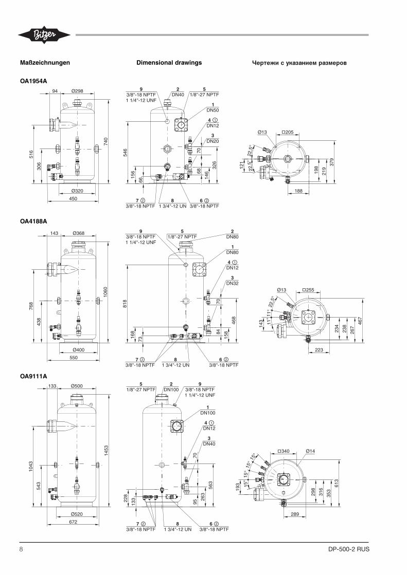
Чертежи с указанием размеров
9DP-500-2 RUSST-130-2 3
2.2 Maximale Ölniveau-Überwa-chung
Elektrischer An schluss und Einbin -dung in die Steue rungs logik sind vonder Konzeption der jeweiligen Anlageabhängig.
So kann beispielsweise bei einerAnlagenkonzeption mit überflutetemVerdampfer ein Magnetventil in derÖlleitung je nach Ölniveau im Verdich -ter angesteuert werden. Ebenso istdie Regelung einer Ölumspeisung imParallelver bund möglich.
2.3 Technische Daten
2.2 Monitoring of the maximumlevel
The electrical connection and its inte-gration into the control logic dependon the design of the particular system.
Thus, for example, in an installationwith flooded evaporator, a solenoidvalve in the oil line can be activated,depending on the oil level in the com-pressor. Likewise, the oil circulationcan also be controlled in parallel.
2.3 Technical data
2.2 Contrôle du niveau d'huile maxi-mal
Le raccordement électrique et l'incorpora-tion à la logique de commande dépen-dent de la conception de l'installation enquestion.
Il est ainsi possible, par exemple dans lecas d'une conception d'installation avecévaporateur noyé, de commander unevanne magnétique dans la conduite d'hui-le, suivant le niveau d'huile dans le com-presseur. La régulation d'un transfertd'huile dans des compresseurs enparallèle est également possible.
2.3 Données tech ni ques
Anschluss-Spannung Supply volt age Tension d'alimentation 230 V AC ± 10% �
Netzfrequenz Supply frequency Fréquence du réseau 50 / 60 Hz
Verzögerungszeit (integriert) Delay time (integrated) Temporisation (integré) 5 s ± 2 s
Vorsicherung für Gerät Fusing for device and Fusible pour appareil etund Schaltkontakte switch contacts contacts de commutation
Maximal zulässiger Druck Maximum allowable pressure Pression maximale admissible
Anschlusskabel Connecting cable Câble de raccordement
Kältemaschinenöle Refrigeration compressor oil Huiles pour machines frigorifiques alle / all / toutes
Kältemittel Refrigerants Fluides frigorigènes
Schutzart (montiert) Enclosure class (mounted) Classe de protection (monté) IP54
Zulässige Umgebungstemperatur Allowable ambient temperature Température ambiante admissible -30 .. +60°C
Gewicht Weight Poids 390 g
� Opto-elektronische Einheit wird alsOLC-D1 ausgeliefert (siehe Seite 2,Abbildung 1, Position 4)
� andere Spannungen auf Anfrage,auch mit UL-Abnahme erhältlich
� Kabel sind farbkodiert
� Opto-electronic unit is delivered asOLC-D1 (see page 2, figure 1, pos. 4)
� other voltages upon request, alsoavailable with UL approval
� Cables are color coded
� Le composant opto-électronique est livréecomme OLC-D1 (voir page 2, figure 1,position 4)
� d'autres types de tension sur demande,aussi avec contrôle UL
� Câbles avec code couleur
5 x AWG 20 (0,75 mm2)L = 2 m �
HFKW, (H)FCKWHFC, (H)CFC
Relais-Ausgänge: Relay output: Sorties de relais:Schaltspannung Switching voltage Tension de commutation max. 240 V ACSchaltstrom Switching current Intensité de commutation max. 2,5 ASchaltleistung Switching capacity Puissance de commutation max. 300 VA
max. 4 A
Maximale Öltemperatur Maximum oil temperature Température d'huile maximale 120°C
33 bar (-20°C .. -10°C) 45 bar (-10°C .. 120°C)
Geräte-Typ Device type Type de dispositif OLC-D1-S �
9
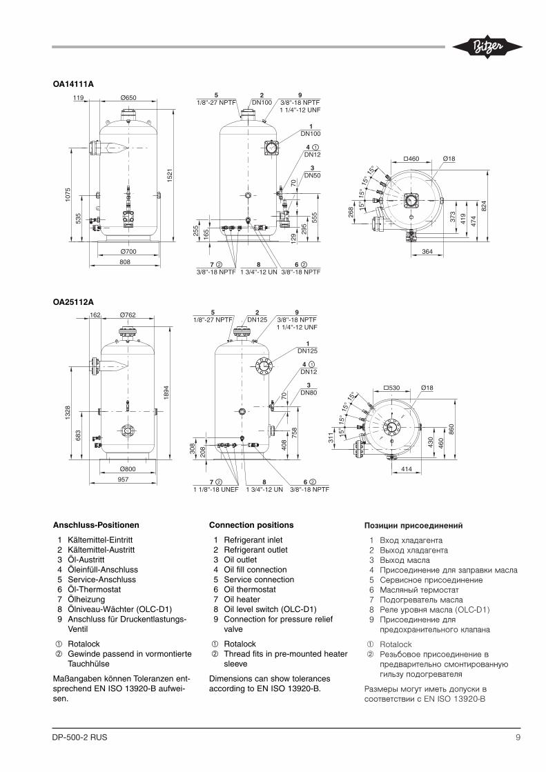
OA14111A
OA25112A
Anschluss-Positionen
1 Kältemittel-Eintritt2 Kältemittel-Austritt3 Öl-Austritt4 Öleinfüll-Anschluss5 Service-Anschluss6 Öl-Thermostat7 Ölheizung8 Ölniveau-Wächter (OLC-D1)9 Anschluss für Druckentlastungs-
Ventil
� Rotalock� Gewinde passend in vormontierte
Tauchhülse
Maßangaben können Toleranzen ent-sprechend EN ISO 13920-B aufwei-sen.
Connection positions
1 Refrigerant inlet2 Refrigerant outlet3 Oil outlet4 Oil fill connection5 Service connection6 Oil thermostat7 Oil heater 8 Oil level switch (OLC-D1)9 Connection for pressure relief
valve
� Rotalock� Thread fits in pre-mounted heater
sleeve
Dimensions can show tolerancesaccording to EN ISO 13920-B.
Position des raccords
1 Entrée de fluide frigorigène2 Sortie de fluide frigorigène3 Sortie d'huile4 Raccord pour le remplissage d'huile5 Raccord pour service6 Thermostat d'huile7 Chauffage d'huile8 Contrôleur de niveau d'huile
(OLC-D1)9 Raccord pour soupape de décharge
� Rotalock� Filetage approprié dans doigt de gant
pré-assemblé
Les dimensions peuvent présenter destolérances conformément à EN ISO13920-B.
DP-500-2
Ø700
1 3/4''-12 UN8
DN12
3/8''-18 NPTF 3/8''-18 NPTF
3
3/8''-18 NPTF1 1/4''-12 UNF
921/8''-27 NPTF
5DN100
DN50
Ø650
1
Ø18460
119
1075
535
1521
70
295
555
808
255
165
DN100
268 15
°15
°15
°15
°
364
373
419
824
474
129
4 1
7 2 6 2
Ø800
1 3/4''-12 UN8
DN12
1 1/8''-18 UNEF 3/8''-18 NPTF
3
3/8''-18 NPTF1 1/4''-12 UNF
921/8''-27 NPTF
5DN125
DN80
Ø762
1
Ø18530
70
308
DN125
408 31
1
162
1328
683
1894
957
208
758
15°
15°
15°
15°
430
460
860
414
4 1
7 2 6 2
Позиции присоединений
1 Входхладагента 2 Выходхладагента 3 Выходмасла 4 Присоединениедлязаправкимасла 5 Сервисноеприсоединение 6 Масляныйтермостат 7 Подогревательмасла 8 Релеуровнямасла(OLCD1) 9 Присоединениедля
предохранительногоклапана
➀ Rotalock ➁ Резьбовоеприсоединениев
предварительносмонтированнуюгильзуподогревателя
РазмерымогутиметьдопускивсоответствиисENISO13920B
10 DP-500-2 RUSST-130-22
2 Functions
The OLC-D1-S can monitor either theminimum or the maximum oil level,depending on its mounting positionand incorporation into the safetychain. If the minimum and the maxi-mum oil level should be monitored,two OLC-D1-S devices must beinstalled.
2.1 Monitoring of the minimumlevel
Lock out
The compressor is shut off, if theprism sticks out of the oil longer thanthe delay time specified by the circuit.
The OLC-D1-S then opens the outputcontact and the circuit locks out elec-tronically: The control voltage to thecompressor contactor is interrupted.The red LED at the face side of theopto-electronic unit lights up (figure 1)as well as the signal lamp H4.
Reset
The circuit can be manually reset bypressing the reset button. This resetbutton (S4) has to be mounted intothe swich board. (Connection seesche matic wiring diagram.)
2 Fonctionnement
Le OLC-D1-S peut contrôler soit leniveau d'huile minimal soit le niveaud'huile maximal, dépendant de la positionde montage et de l'intégration dans lachaîne de sécurité. Pour surveiller leniveau d'huile minimal et maximal enmême temps, deux OLC-D1-S doiventêtre installés.
2.1 Contrôle du niveau d'huile minimal
Verrouiller
Le compresseur est arrêté des lors que letemps pendant lequel le cône de verredépasse le niveau d'huile est supérieur àla la temporisation prédéfinie par leréglage.
Le OLC-D1-S ouvre alors le contact desortie et le circuit se verrouille électroni-quement: la tension de commande ducon tacteur du compresseur est alorscoupée. La LED rouge sur le côté frontalde l'unité opto-électronique s'allume (figu-re 1) et ainsi que la lampe H4.
Déverrouiller
Le circuit peut être remis manuellementen fonctionnement par la touche de reset.Cette touche (S4) devra être montéedans l'armoire électrique. (Raccordementvoir schéma de principe.)
2 Funktionen
Das OLC-D1-S kann entweder dasmini male oder das maximale Ölnive auüber wachen, je nach Montage-Posi ti -on und Einbettung in die Sicher heits -kette. Falls sowohl das mini male wiedas maximale Ölnive au über wachtwerden soll, müssen zwei OLC-D1-Sinstalliert werden.
2.1 Minimale Ölniveau-Überwa-chung
Verriegeln
Der Verdichter wird abgeschaltet,wenn der Glas-Kegel länger als diedurch die Schaltung vorgegebene Ver -zöge rungs zeit aus dem Öl herausragt.
Das OLC-D1-S öffnet dann den Aus -gangs kon takt und die Schaltung ver-riegelt elektronisch: Die Steuerspan -nung zum Verdich ter schütz wird unter-brochen. Die rote LED auf der Stirn -seite der opto-elektronischen Ein heit(Abb. 1) und die Signallampe H4leuchten.
Entriegeln
Die Schaltung kann über eine Reset-Taste manuell zurück gesetzt werden.Diese Reset-Taste (S4) muss imSchalt schrank montiert werden.(Anschluss siehe Prinzipschaltbild.)
Abb. 1 Abmessungen und Aufbau Fig. 1 Dimensions and design
�
� � �
�
�
�
�
� � � � � � � � � � � � � � � � � � �
�
Fig. 1 Dimensions et construction
1 Prisma-Einheit2 Glas-Kegel3 Dichtung4 Opto-elektronische Einheit "OLC-D1"
(360° drehbar)5 Anschlusskabel6 Schraubkappe
1 Prism unit2 Glass cone3 Gasket4 Opto-electronic unit "OLC-D1"
(360° revolving)5 Connecting cable6 Screwing cap
1 Unité prisme2 Cône en verre3 Joint4 Composant opto-électronique "OLC-D1"
(mobile sur 360°)5 Câble de raccordement6 Chapeau à visser
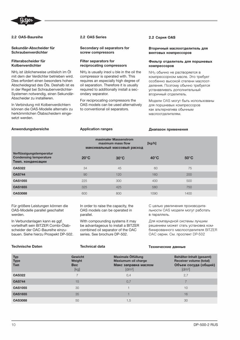
2.2 OAS-Baureihe
Sekundär-AbscheiderfürSchraubenverdichter
FilterabscheiderfürKolbenverdichter
NH3istüblicherweiseunlöslichimÖlmitdemderVerdichterbetriebenwird.Dies erfordert einen besonders hohen Abscheidegrad des Öls. Deshalb ist es inderRegelbeiSchraubenverdichter-Systemennotwendig,einenSekundär-Abscheider zu installieren.
InVerbindungmitKolbenverdichternkönnendieOAS-ModellealternativzuherkömmlichenÖlabscheiderneinge-setztwerden.
TechnischeDaten
Anwendungsbereiche
2.2 OASSeries
Secondaryoilseparatorsforscrewcompressors
Filterseparatorsforreciprocatingcompressors
NH3 is usually insol u ble in the oil the compressorisoperatedwith.Thisrequires an especially high degree of oilseparation.Thereforeitisusuallyrequired to additionally install a sec-ondary separator.
For reciprocating compressors the OASmodelscanbeusedalternativelytoconventionaloilseparators.
Technicaldata
Applicationranges
2.2 Серия OAS
Вторичный маслоотделитель для винтовых компрессоров
Фильтр отделитель для поршневых компрессоров
NH3обычнонерастворяетсявкомпрессорноммасле.Этотребуетособенновысокойстепенимаслоотделения.Поэтомуобычнотребуетсяустанавливатьдополнительныйвторичныйотделитель.
МоделиOASмогутбытьиспользованыдляпоршневыхкомпрессоровкакальтернативаобычныммаслоотделителям.
Технические данные
Диапазон применения
maximalerMassenstrommaximummassflow
максимальный массовый расход
VerflüssigungstemperaturCondensingtemperatureТемп. конденсации
20°C 30°C 40°C 50°C
OAS322 34 45 60 75
OAS744 90 120 160 200
OAS1055 225 300 400 500
OAS1655 325 425 580 750
OAS3088 600 800 1090 1400
TypTypeТип
GewichtWeightВес
[kg]
MaximaleÖlfüllungMaxiumumoilchargeМакс заправка маслом
[dm3]
Behälter-Inhalt(gesamt)Receivervolume(total)Объем сосуда (общий)
[dm3]
OAS322 7 0,4 2,7
OAS744 15 0,7 7
OAS1055 30 1 10
OAS1655 35 1 16
OAS3088 50 1,5 30
FürgrößereLeistungenkönnendieOAS-Modelleparallelgeschaltetwerden.
InVerbundanlagenkannesggf.vorteilhaftseinBITZERCombi-Ölab- scheider der OAC-Baureihe einzu-bauen.SiehehierzuProspektDP-502.
Inordertoraisethecapacity,theOAS models can be operated in parallel.
With compounding systems it may beadvantageoustoinstallaBITZERcombined oil separator of the OAC series.SeebrochureDP-502.
СцельюувеличенияпроизводительностиOASмоделимогутработатьвпараллель.
ДлякомпаунднойсистемылучшимрешениемможетстатьустановкакомбинированногомаслоотделителяBITZEROACсерии.См.проспектDP502
[kg/h]

11DP-500-2 RUSST-130-2 3
2.2 Maximale Ölniveau-Überwa-chung
Elektrischer An schluss und Einbin -dung in die Steue rungs logik sind vonder Konzeption der jeweiligen Anlageabhängig.
So kann beispielsweise bei einerAnlagenkonzeption mit überflutetemVerdampfer ein Magnetventil in derÖlleitung je nach Ölniveau im Verdich -ter angesteuert werden. Ebenso istdie Regelung einer Ölumspeisung imParallelver bund möglich.
2.3 Technische Daten
2.2 Monitoring of the maximumlevel
The electrical connection and its inte-gration into the control logic dependon the design of the particular system.
Thus, for example, in an installationwith flooded evaporator, a solenoidvalve in the oil line can be activated,depending on the oil level in the com-pressor. Likewise, the oil circulationcan also be controlled in parallel.
2.3 Technical data
2.2 Contrôle du niveau d'huile maxi-mal
Le raccordement électrique et l'incorpora-tion à la logique de commande dépen-dent de la conception de l'installation enquestion.
Il est ainsi possible, par exemple dans lecas d'une conception d'installation avecévaporateur noyé, de commander unevanne magnétique dans la conduite d'hui-le, suivant le niveau d'huile dans le com-presseur. La régulation d'un transfertd'huile dans des compresseurs enparallèle est également possible.
2.3 Données tech ni ques
Anschluss-Spannung Supply volt age Tension d'alimentation 230 V AC ± 10% �
Netzfrequenz Supply frequency Fréquence du réseau 50 / 60 Hz
Verzögerungszeit (integriert) Delay time (integrated) Temporisation (integré) 5 s ± 2 s
Vorsicherung für Gerät Fusing for device and Fusible pour appareil etund Schaltkontakte switch contacts contacts de commutation
Maximal zulässiger Druck Maximum allowable pressure Pression maximale admissible
Anschlusskabel Connecting cable Câble de raccordement
Kältemaschinenöle Refrigeration compressor oil Huiles pour machines frigorifiques alle / all / toutes
Kältemittel Refrigerants Fluides frigorigènes
Schutzart (montiert) Enclosure class (mounted) Classe de protection (monté) IP54
Zulässige Umgebungstemperatur Allowable ambient temperature Température ambiante admissible -30 .. +60°C
Gewicht Weight Poids 390 g
� Opto-elektronische Einheit wird alsOLC-D1 ausgeliefert (siehe Seite 2,Abbildung 1, Position 4)
� andere Spannungen auf Anfrage,auch mit UL-Abnahme erhältlich
� Kabel sind farbkodiert
� Opto-electronic unit is delivered asOLC-D1 (see page 2, figure 1, pos. 4)
� other voltages upon request, alsoavailable with UL approval
� Cables are color coded
� Le composant opto-électronique est livréecomme OLC-D1 (voir page 2, figure 1,position 4)
� d'autres types de tension sur demande,aussi avec contrôle UL
� Câbles avec code couleur
5 x AWG 20 (0,75 mm2)L = 2 m �
HFKW, (H)FCKWHFC, (H)CFC
Relais-Ausgänge: Relay output: Sorties de relais:Schaltspannung Switching voltage Tension de commutation max. 240 V ACSchaltstrom Switching current Intensité de commutation max. 2,5 ASchaltleistung Switching capacity Puissance de commutation max. 300 VA
max. 4 A
Maximale Öltemperatur Maximum oil temperature Température d'huile maximale 120°C
33 bar (-20°C .. -10°C) 45 bar (-10°C .. 120°C)
Geräte-Typ Device type Type de dispositif OLC-D1-S �
11
Maßzeichnungen
OAS322 & OAS744
Anschluss-Positionen
1 Kältemittel-Eintritt2 Kältemittel-Austritt3 Öl-Austritt5 Service-Anschluss
Abmessungen
Das Maß X ist der Ausbaufreiraumder Filterpatrone. Dieser Freiraummuss unterhalb des Sekundär-Ölab-scheiders vorgesehen werden, damitdie Filterpatro ne bei Wartungsarbeitennach unten herausgenommen werdenkann.
Dimensional drawings
OAS1055 .. OAS3088
Connection positions
1 Refrigerant inlet2 Refrigerant outlet3 Oil outlet5 Service connection
Dimensions
The dimension X is the removal spaceof the filter cartridge. This space mustbe provided under the secondary sep-arator, so the filter cartridge can bepulled out from below in case of main-tenance.
Croquis cotés
Position des raccords
1 Entrée de fluide frigorigène2 Sortie de fluide frigorigène3 Sortie d'huile5 Raccord pour service
Dimensions
La dimension X est l'espace d'énlevagepour la cartouche filtrante. Cette espacedoit être prévue sous le séparateursecondaire pour retirer la cartouche fil-trante de dessous en cas de maintenan-ce.
DP-500-2
� �
�
�
��
�
� �
�
�
��
�
�
� �
� � � � � � � � �
�� �
� �
�
� � �
�
�
�
A B D D1 E F G H I K L S X Z 1 2
OAS1055 800 414 159 --- 533 733 110 400 133 239 175 95 300 6 DN50 DN50
OAS1655 1100 414 159 --- 833 1033 110 400 243 239 175 95 600 6 DN50 DN50
OAS322 403 189 159 108 268 --- 110 246 --- 110 --- 63 120 6 13/4''-12UNF 13/4''-12UNF
OAS744 507 233 159 159 398 --- 110 300 83 138 --- 96 260 6 21/4''-12UN 21/4''-12UN
OAS3088 1210 506 216 --- 859 1129 180 400 249 278 228 118 600 7 DN80 DN80
��
�
��
�
� �
�
� �
�
� ��
� � �
� � �
��
� �
� �
�
�
�
Чертежи с указанием размеров
Позиции присоединений
1 Входхладагента 2 Выходхладагента 3 Выходмасла 5 Сервисноеприсоединение
РазмерXэтопространствонеобходимоедлязаменыфильтрующегоэлемента.Этопространстводолжнобытьобеспеченоподвторичнымотделителем,такимобразом,фильтрующийэлемент,можетбыть,вынутснизуприобслуживании.
Размеры

BITZER Kühlmaschinenbau GmbH
Eschenbrünnlestraße 15 // 71065 Sindelfingen // Germany
Tel +49 (0)70 31 932-0 // Fax +49 (0)70 31 932-147
[email protected] // www.bitzer.de
Subject to change // Änderungen vorbehalten // Toutes modifications réservées // 80420701 // 05.2010Subject to change // Änderungen vorbehalten // Оставляем за собой право вносить изменения 10.2016
BITZER Kühlmaschinenbau GmbH
Eschenbrünnlestraße 15 // 71065 Sindelfingen // Germany
Tel +49 (0)70 31 932-0 // Fax +49 (0)70 31 932-147
[email protected] // www.bitzer.de
Subject to change // Änderungen vorbehalten // Toutes modifications réservées // 80420701 // 05.2010
BITZER Kühlmaschinenbau GmbH
Eschenbrünnlestraße 15 // 71065 Sindelfingen // Germany
Tel +49 (0)70 31 932-0 // Fax +49 (0)70 31 932-147
[email protected] // www.bitzer.de
Subject to change // Änderungen vorbehalten // Toutes modifications réservées // 80420701 // 05.2010
BITZER Kühlmaschinenbau GmbH
Eschenbrünnlestraße 15 // 71065 Sindelfingen // Germany
Tel +49 (0)70 31 932-0 // Fax +49 (0)70 31 932-147
[email protected] // www.bitzer.de
Subject to change // Änderungen vorbehalten // Toutes modifications réservées // 80420701 // 05.2010